WO2023219144A1 - 音響システム及び車両 - Google Patents
音響システム及び車両 Download PDFInfo
- Publication number
- WO2023219144A1 WO2023219144A1 PCT/JP2023/017807 JP2023017807W WO2023219144A1 WO 2023219144 A1 WO2023219144 A1 WO 2023219144A1 JP 2023017807 W JP2023017807 W JP 2023017807W WO 2023219144 A1 WO2023219144 A1 WO 2023219144A1
- Authority
- WO
- WIPO (PCT)
- Prior art keywords
- seat
- vehicle
- occupant
- mode
- sound
- Prior art date
- Legal status (The legal status is an assumption and is not a legal conclusion. Google has not performed a legal analysis and makes no representation as to the accuracy of the status listed.)
- Ceased
Links
Images














Classifications
-
- B—PERFORMING OPERATIONS; TRANSPORTING
- B60—VEHICLES IN GENERAL
- B60N—SEATS SPECIALLY ADAPTED FOR VEHICLES; VEHICLE PASSENGER ACCOMMODATION NOT OTHERWISE PROVIDED FOR
- B60N2/00—Seats specially adapted for vehicles; Arrangement or mounting of seats in vehicles
- B60N2/80—Head-rests
- B60N2/879—Head-rests with additional features not related to head-rest positioning, e.g. heating or cooling devices or loudspeakers
-
- A—HUMAN NECESSITIES
- A47—FURNITURE; DOMESTIC ARTICLES OR APPLIANCES; COFFEE MILLS; SPICE MILLS; SUCTION CLEANERS IN GENERAL
- A47C—CHAIRS; SOFAS; BEDS
- A47C7/00—Parts, details, or accessories of chairs or stools
- A47C7/36—Supports for the head or the back
- A47C7/38—Supports for the head or the back for the head, e.g. detachable
-
- A—HUMAN NECESSITIES
- A47—FURNITURE; DOMESTIC ARTICLES OR APPLIANCES; COFFEE MILLS; SPICE MILLS; SUCTION CLEANERS IN GENERAL
- A47C—CHAIRS; SOFAS; BEDS
- A47C7/00—Parts, details, or accessories of chairs or stools
- A47C7/62—Accessories for chairs
- A47C7/72—Adaptations for incorporating lamps, radio sets, bars, telephones, ventilation, heating or cooling arrangements or the like
-
- B—PERFORMING OPERATIONS; TRANSPORTING
- B60—VEHICLES IN GENERAL
- B60N—SEATS SPECIALLY ADAPTED FOR VEHICLES; VEHICLE PASSENGER ACCOMMODATION NOT OTHERWISE PROVIDED FOR
- B60N2/00—Seats specially adapted for vehicles; Arrangement or mounting of seats in vehicles
- B60N2/002—Seats provided with an occupancy detection means mounted therein or thereon
- B60N2/0021—Seats provided with an occupancy detection means mounted therein or thereon characterised by the type of sensor or measurement
- B60N2/0022—Seats provided with an occupancy detection means mounted therein or thereon characterised by the type of sensor or measurement for sensing anthropometric parameters, e.g. heart rate or body temperature
-
- B—PERFORMING OPERATIONS; TRANSPORTING
- B60—VEHICLES IN GENERAL
- B60N—SEATS SPECIALLY ADAPTED FOR VEHICLES; VEHICLE PASSENGER ACCOMMODATION NOT OTHERWISE PROVIDED FOR
- B60N2/00—Seats specially adapted for vehicles; Arrangement or mounting of seats in vehicles
- B60N2/002—Seats provided with an occupancy detection means mounted therein or thereon
- B60N2/0021—Seats provided with an occupancy detection means mounted therein or thereon characterised by the type of sensor or measurement
- B60N2/0023—Seats provided with an occupancy detection means mounted therein or thereon characterised by the type of sensor or measurement for detection of driver fatigue
-
- B—PERFORMING OPERATIONS; TRANSPORTING
- B60—VEHICLES IN GENERAL
- B60N—SEATS SPECIALLY ADAPTED FOR VEHICLES; VEHICLE PASSENGER ACCOMMODATION NOT OTHERWISE PROVIDED FOR
- B60N2/00—Seats specially adapted for vehicles; Arrangement or mounting of seats in vehicles
- B60N2/90—Details or parts not otherwise provided for
-
- B—PERFORMING OPERATIONS; TRANSPORTING
- B60—VEHICLES IN GENERAL
- B60R—VEHICLES, VEHICLE FITTINGS, OR VEHICLE PARTS, NOT OTHERWISE PROVIDED FOR
- B60R11/00—Arrangements for holding or mounting articles, not otherwise provided for
- B60R11/02—Arrangements for holding or mounting articles, not otherwise provided for for radio sets, television sets, telephones, or the like; Arrangement of controls thereof
-
- B—PERFORMING OPERATIONS; TRANSPORTING
- B62—LAND VEHICLES FOR TRAVELLING OTHERWISE THAN ON RAILS
- B62J—CYCLE SADDLES OR SEATS; AUXILIARY DEVICES OR ACCESSORIES SPECIALLY ADAPTED TO CYCLES AND NOT OTHERWISE PROVIDED FOR, e.g. ARTICLE CARRIERS OR CYCLE PROTECTORS
- B62J1/00—Saddles or other seats for cycles; Arrangement thereof; Component parts
- B62J1/12—Box-shaped seats; Bench-type seats, e.g. dual or twin seats
-
- B—PERFORMING OPERATIONS; TRANSPORTING
- B62—LAND VEHICLES FOR TRAVELLING OTHERWISE THAN ON RAILS
- B62J—CYCLE SADDLES OR SEATS; AUXILIARY DEVICES OR ACCESSORIES SPECIALLY ADAPTED TO CYCLES AND NOT OTHERWISE PROVIDED FOR, e.g. ARTICLE CARRIERS OR CYCLE PROTECTORS
- B62J43/00—Arrangements of batteries
- B62J43/20—Arrangements of batteries characterised by the mounting
-
- H—ELECTRICITY
- H04—ELECTRIC COMMUNICATION TECHNIQUE
- H04R—LOUDSPEAKERS, MICROPHONES, GRAMOPHONE PICK-UPS OR LIKE ACOUSTIC ELECTROMECHANICAL TRANSDUCERS; ELECTRIC HEARING AIDS; PUBLIC ADDRESS SYSTEMS
- H04R1/00—Details of transducers, loudspeakers or microphones
- H04R1/02—Casings; Cabinets ; Supports therefor; Mountings therein
- H04R1/025—Arrangements for fixing loudspeaker transducers, e.g. in a box, furniture
-
- H—ELECTRICITY
- H04—ELECTRIC COMMUNICATION TECHNIQUE
- H04R—LOUDSPEAKERS, MICROPHONES, GRAMOPHONE PICK-UPS OR LIKE ACOUSTIC ELECTROMECHANICAL TRANSDUCERS; ELECTRIC HEARING AIDS; PUBLIC ADDRESS SYSTEMS
- H04R3/00—Circuits for transducers
-
- H—ELECTRICITY
- H04—ELECTRIC COMMUNICATION TECHNIQUE
- H04R—LOUDSPEAKERS, MICROPHONES, GRAMOPHONE PICK-UPS OR LIKE ACOUSTIC ELECTROMECHANICAL TRANSDUCERS; ELECTRIC HEARING AIDS; PUBLIC ADDRESS SYSTEMS
- H04R3/00—Circuits for transducers
- H04R3/12—Circuits for transducers for distributing signals to two or more loudspeakers
-
- H—ELECTRICITY
- H04—ELECTRIC COMMUNICATION TECHNIQUE
- H04R—LOUDSPEAKERS, MICROPHONES, GRAMOPHONE PICK-UPS OR LIKE ACOUSTIC ELECTROMECHANICAL TRANSDUCERS; ELECTRIC HEARING AIDS; PUBLIC ADDRESS SYSTEMS
- H04R5/00—Stereophonic arrangements
- H04R5/02—Spatial or constructional arrangements of loudspeakers
- H04R5/023—Spatial or constructional arrangements of loudspeakers in a chair, pillow
-
- H—ELECTRICITY
- H04—ELECTRIC COMMUNICATION TECHNIQUE
- H04S—STEREOPHONIC SYSTEMS
- H04S7/00—Indicating arrangements; Control arrangements, e.g. balance control
- H04S7/30—Control circuits for electronic adaptation of the sound field
- H04S7/302—Electronic adaptation of stereophonic sound system to listener position or orientation
- H04S7/303—Tracking of listener position or orientation
-
- B—PERFORMING OPERATIONS; TRANSPORTING
- B60—VEHICLES IN GENERAL
- B60N—SEATS SPECIALLY ADAPTED FOR VEHICLES; VEHICLE PASSENGER ACCOMMODATION NOT OTHERWISE PROVIDED FOR
- B60N2230/00—Communication or electronic aspects
- B60N2230/30—Signal processing of sensor data
-
- H—ELECTRICITY
- H04—ELECTRIC COMMUNICATION TECHNIQUE
- H04R—LOUDSPEAKERS, MICROPHONES, GRAMOPHONE PICK-UPS OR LIKE ACOUSTIC ELECTROMECHANICAL TRANSDUCERS; ELECTRIC HEARING AIDS; PUBLIC ADDRESS SYSTEMS
- H04R2430/00—Signal processing covered by H04R, not provided for in its groups
- H04R2430/01—Aspects of volume control, not necessarily automatic, in sound systems
-
- H—ELECTRICITY
- H04—ELECTRIC COMMUNICATION TECHNIQUE
- H04R—LOUDSPEAKERS, MICROPHONES, GRAMOPHONE PICK-UPS OR LIKE ACOUSTIC ELECTROMECHANICAL TRANSDUCERS; ELECTRIC HEARING AIDS; PUBLIC ADDRESS SYSTEMS
- H04R2499/00—Aspects covered by H04R or H04S not otherwise provided for in their subgroups
- H04R2499/10—General applications
- H04R2499/13—Acoustic transducers and sound field adaptation in vehicles
Definitions
- the present invention relates to a sound system and a vehicle, and particularly to a sound system and a vehicle having an interior member equipped with a speaker.
- Patent Document 1 discloses a vehicle seat that includes a speaker and a noise canceling microphone in a headrest.
- the headrest described in Patent Document 1 is provided with a speaker and a microphone, audio is output regardless of the occupant's condition. Therefore, depending on the posture of the occupant, the sound emitted from the speaker may feel strange. Therefore, it has been desired to generate sounds that are appropriate for the occupant's condition, such as to make the sound more perceptible or to suppress the sense of discomfort.
- the present invention has been made in view of the above-mentioned problems, and an object of the present invention is to provide an audio system and a vehicle that emit sounds suitable for the condition of the occupant.
- an object of the present invention is to provide an audio system and a vehicle that emit sounds suitable for the condition of the occupant.
- other purposes include improving the workability of attaching harnesses and connectors, suppressing the increase in size of the headrest, and suppressing vibrations of the headrest.
- an interior member for a vehicle that includes at least one speaker; a state detection section that detects a state of a passenger or the interior member; and a state detection section that includes the speaker and the state detection section.
- a control unit that connects and controls the speaker; the control unit includes a state determination unit that determines the state of the occupant or the interior member based on information received from the state detection unit; and a sound control unit that controls at least one of the volume, tempo, and direction of the sound emitted from the speaker based on the determined state of the occupant or the interior member when the sound is emitted.
- a sound control unit controls at least one of the volume, tempo, and direction of sound emitted from a speaker based on the state of the passenger or an interior member, so that a sound suitable for the passenger is generated. I can do it.
- the condition detection section is capable of acquiring biological information of the occupant, and the condition determination section determines the condition of the occupant based on the biological information of the occupant,
- the sound control unit may control the sound emitted from the speaker based on the condition of the occupant.
- the sound control unit controls the sound based on the occupant's biological information, so that the speaker can emit a sound that is more suitable for the occupant.
- the state determination unit determines the alertness level of the occupant based on biological information of the occupant
- the sound control unit determines the alertness level of the occupant based on the determined alertness level of the occupant. It is preferable to control the sound emitted from the speaker. Since the sound control unit controls the sound emitted from the speaker based on the alertness level of the occupant, it becomes possible to emit more appropriate sound based on the alertness level of the occupant.
- the sound control unit may increase the volume of the sound emitted from the speaker or increase the tempo of the sound when the alertness level of the occupant decreases.
- the acoustic control unit increases the volume of the sound emitted from the speaker or increases the tempo of the audio, thereby increasing the alertness level of the occupant, for example.
- the interior member is a vehicle seat on which the occupant is seated, and the vehicle seat has at least two of the speakers arranged apart from each other in the width direction of the seat, and
- the state determining section determines the occupant's posture or the position of the vehicle seat based on the information received from the state detecting section, and the sound control section determines the determined posture of the occupant or the position of the vehicle seat.
- the sound emitted from the speaker may be controlled based on the position.
- the sound control unit can emit a sound that is more suitable for the occupant.
- the vehicle seat is rotatable with the seat up and down direction as a rotation axis
- the state determination section determines a rotation angle of the vehicle seat
- the sound control section determines a rotation angle of the vehicle seat.
- the sound emitted from the speaker may be controlled based on the rotation angle.
- the sound control unit can emit sound that is more suitable for the occupant.
- the vehicle interior member is a plurality of rows of vehicle seats arranged in a longitudinal direction
- the state determination unit is configured to determine whether the occupant is seated in each of the vehicle seats.
- the sound control unit may control the sound emitted from the speaker depending on the seating state of the occupant. By controlling the sound according to the seating state of the occupant, the sound control unit can emit a sound suitable for the occupant seated in a plurality of rows of vehicle seats.
- the state determination unit determines the position of the head of the occupant, and the sound control unit controls the sound output from the speaker based on the determined position of the head of the occupant.
- the audio may be controlled.
- the sound control unit can emit a sound that is more suitable for the occupant.
- the interior member is a vehicle seat on which the occupant is seated, and the vehicle seat preferably includes a damper for suppressing vibrations at a position adjacent to the speaker.
- the vehicle seat preferably includes a damper for suppressing vibrations at a position adjacent to the speaker.
- the vehicle seat includes a headrest that supports the head of the occupant, and the vehicle seat includes at least two headrests disposed within the headrest and spaced apart in the seat width direction.
- the headrest may have a headrest pillar serving as a skeleton, and the damper may be attached to the headrest pillar at a position sandwiched between the two speakers. Since the damper is attached to the headrest pillar at a position sandwiched between the two speakers, vibration of the headrest caused by the speakers can be suppressed.
- the sound control unit controls at least one of the volume, tempo, and direction of the sound emitted from the speaker based on the state of the passenger or interior components, so that the sound is suitable for the passenger. It is possible to provide a sound system that generates. Furthermore, the sound control section controls the sound based on the occupant's biological information, so that the speaker can emit a sound that is more suitable for the occupant. Moreover, the sound control unit controls the sound emitted from the speaker based on the occupant's level of alertness, so that more appropriate sound can be emitted based on the level of alertness of the occupant.
- the acoustic control unit can increase the volume of the sound emitted from the speaker or increase the tempo of the audio, thereby increasing the alertness level of the occupant, for example.
- the sound control section controls the sound based on the posture of the passenger or the position of the vehicle seat, thereby making it possible to emit sound more suitable for the passenger.
- the sound control unit can emit sound that is more suitable for the occupant.
- the sound control unit can emit a sound suitable for the occupant seated in a plurality of rows of vehicle seats.
- the sound control section controls the sound based on the position of the occupant's head, thereby making it possible to emit a sound that is more suitable for the occupant. Further, by providing a damper at a position adjacent to the speaker, it is possible to suppress vibrations of interior members caused by, for example, sound emitted from the speaker. Further, since the damper is attached to the headrest pillar at a position sandwiched between the two speakers, it is possible to suppress vibration of the headrest caused by the speakers, for example.
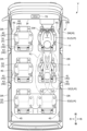
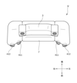
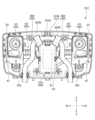
- FIG. 1 is a diagram illustrating a vehicle and a vehicle interior equipped with an audio system according to a first embodiment.
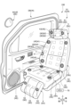
- FIG. 2 is a perspective view showing a door and a vehicle seat, which are interior members. It is an explanatory view showing operation of a speaker of a vehicle seat.
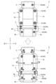
- FIG. 3 is a diagram illustrating another example of a vehicle seat, and is an explanatory diagram for explaining changing the direction of sound using a plurality of speakers, and is a view of the seat back viewed from the front.
- FIG. 3 is a diagram showing another example of a vehicle seat, and is an explanatory diagram for explaining changing the direction of sound using a plurality of speakers, and is a view of the seat back viewed from above.
- FIG. 1 is a diagram illustrating a vehicle and a vehicle interior equipped with an audio system according to a first embodiment.
- FIG. 2 is a perspective view showing a door and a vehicle seat, which are interior members. It is an explanatory view showing operation of a speaker of
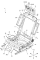
- FIG. 2 is a perspective view showing a frame of a vehicle seat.
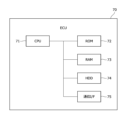
- FIG. 2 is a block diagram showing the hardware configuration of an ECU that controls the audio system.
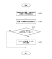
- FIG. 2 is a block diagram showing the functional configuration of the audio system. It is a flowchart explaining the operation of the sound system.
- FIG. 3 is a diagram showing the inside of a vehicle in which the orientation of the mid-seat has been changed.
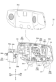
- FIG. 3 is an exploded perspective view of a headrest frame having a damper.
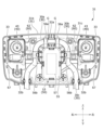
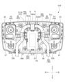
- FIG. 3 is a diagram showing a headrest frame having a damper, with a front cover removed.
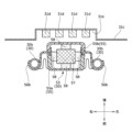
- FIG. 11 is a cross-sectional view taken along line BB in FIG. 10, and is an explanatory diagram for explaining the positional relationship between the damper and the connecting member that supports the connector.
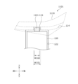
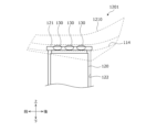
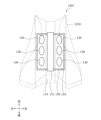
- FIG. 2 is an explanatory diagram for explaining the position of a damper, and is a schematic diagram of the vehicle seat viewed from the front. It is an explanatory view for explaining the position of a damper, and is a schematic diagram of a vehicle seat seen from the side.
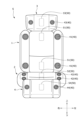
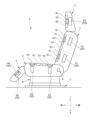
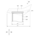
- FIG. 3 is a left side view of a motorcycle according to a second embodiment. 1 is a schematic configuration diagram of a first embodiment of a vehicle seat assembly provided in a motorcycle, viewed from the side; FIG. FIG.
- FIG. 1 is a schematic configuration diagram of a vehicle seat assembly according to a first embodiment seen from above.
- FIG. 3 is a perspective view showing the back surface of the seat of the vehicle seat assembly of the first embodiment.
- FIG. 2 is a schematic configuration diagram of a vehicle seat assembly according to a second embodiment, viewed from the side.
- FIG. 2 is a schematic configuration diagram of a vehicle seat assembly according to a second embodiment, viewed from above.
- FIG. 7 is a perspective view showing the back surface of the seat of the vehicle seat assembly of the second embodiment.
- FIG. 3 is a schematic configuration diagram of a vehicle seat assembly according to a third embodiment when viewed from the side.
- FIG. 7 is a schematic configuration diagram of a vehicle seat assembly according to a third embodiment, viewed from above.
- FIG. 7 is a perspective view showing the back surface of the seat of the vehicle seat assembly according to the third embodiment.
- FIG. 7 is a schematic configuration diagram of a vehicle seat assembly according to a fourth embodiment when viewed from the side.
- FIG. 7 is a schematic configuration diagram of a vehicle seat assembly according to a fourth embodiment, viewed from above.
- FIG. 7 is a perspective view showing the back surface of the seat of the vehicle seat assembly according to the fourth embodiment. It is a figure which shows typically the structure of the electric vehicle of 3rd embodiment.
- FIG. 2 is a perspective view of a vehicle seat.
- FIG. 6 is a diagram illustrating a state in which the side portion of the seat back is in a "normal position.”
- FIG. 3 is a diagram illustrating a state in which the side portions of the seat back are in the "protruding position.” It is a block diagram of an electric vehicle.
- FIG. 3 is a diagram showing a main flow in controlling an electric vehicle.
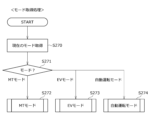
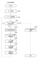
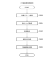
- FIG. 3 is a diagram showing a flow of control regarding occupant identification processing. It is a figure showing the flow of control regarding fellow passenger detection processing. It is a figure showing the flow of mode decision processing (part 1). It is a figure showing the flow of mode decision processing (part 2). It is a figure showing the flow of mode decision processing (part 3). It is a figure showing the flow of mode acquisition control processing. It is a figure showing the flow of parts control processing. It is a figure showing the flow of mobile device control processing.
- the vehicle V provided with the audio system 100 is a self-driving automobile, and its configuration example will be explained.
- the "front-back direction” refers to the front-back direction of the vehicle V, and is a direction that coincides with the traveling direction of the vehicle when it is running.
- the "width direction” is the width direction of the vehicle V
- the “vertical direction” is the vertical direction of the vehicle V, and is a direction that coincides with the vertical direction when the vehicle V is running on a horizontal plane.
- the vehicle is added to various directions such as “seat width direction” and “seat height direction”
- the direction with respect to the vehicle seat S mounted on the vehicle V is used.
- vehicle when described with “vehicle” attached, such as “vehicle inside” or “vehicle outside”, the direction with respect to the vehicle V is indicated.
- the vehicle V is an automobile having multiple rows of vehicle seats S, as shown in FIG.
- the vehicle V includes a front seat S1 located at the front, a mid seat S2 located behind the front seat S1, and a rear seat S3 located at the rearmost position.
- the rear seat S3 is formed by connecting the left and right seats and being formed as a single body, the rear seat S3 may be formed as an independent seat.
- the front seat S1, mid seat S2, and rear seat S3 basically have the same configuration, and in the following description, unless there is a need to distinguish them, they will be referred to as vehicle seats S.
- the vehicle V also includes a steering wheel SW operated by the driver and an instrument panel IP.
- the instrument panel IP is provided with an operation panel, and the occupant H of the vehicle V can change music playing in the vehicle interior, seat position, etc. by inputting the same into the operation panel.
- Vehicle doors DR that can be opened and closed with respect to the vehicle body are provided on the left and right outer sides of each vehicle seat S, respectively, and the occupant H seated on each vehicle seat S opens the vehicle doors DR on the left and right outer sides. By opening it, it is possible to get on and off the vehicle V.
- the vehicle door DR corresponds to the interior member M of the present invention.
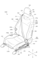
- FIG. 2 is a perspective view showing an interior member M of a vehicle V equipped with the acoustic system 100 according to the present embodiment.
- FIG. 2 shows, as interior members M, a front seat S1 located at the front and right side of the vehicle V, and a vehicle door DR located on the right outer side thereof.
- FIG. 3A is a front view showing the vehicle seat S including the front seat S1, with the upper row showing the state before both sides of the vehicle seat S are deformed, and the lower row showing the state after the both sides have been deformed.
- 3B and 3C are diagrams showing another example of the vehicle seat S.
- FIG. 4 is a perspective view showing a frame of the vehicle seat S including the front seat S1. Note that, for convenience of illustration, a part of the front seat S1 in FIG. 2 is shown with the outer skin T removed and the pad P exposed.
- the configuration of the vehicle seat S including the front seat S1 will be explained.
- the vehicle seat S is provided with a seat back 1 that supports the back of a seated occupant H, a seat cushion 2 that supports the thighs and buttocks of the occupant H, and an upper end of the seat back 1. It is equipped with a headrest 3 that supports the head.
- the vehicle seat S also includes an ottoman 4 that supports the legs of the occupant H. Below, the seat back 1, the seat cushion 2, the headrest 3, and the ottoman 4 may be collectively referred to as a seat body Sh.
- the vehicle seat S is provided with a plurality of speakers 40, which are sound generating devices that emit sound.
- Each of the speakers 40 is connected by a cable to an ECU 70 (control unit) provided in the vehicle, and can emit music, warning sounds, etc. according to instructions from the ECU 70.
- ECU 70 control unit
- back speakers 41 are arranged on the left and right sides of the upper and lower ends of the seat back 1, respectively.
- Cushion speakers 42 are arranged on the left and right sides of the front end and rear end of the seat cushion 2, respectively.
- Headrest speakers 43 are arranged at both left and right ends of the headrest 3, respectively.
- Ottoman speakers 44 are arranged at both left and right ends of the ottoman 4, respectively.
- a door speaker 45 is also arranged below the vehicle door DR, which is the interior member M.
- the back speaker 41, the cushion speaker 42, the headrest speaker 43, the ottoman speaker 44, and the door speaker 45 each have the same configuration as the function of emitting sound. Note that in the following description, the speaker 40 may be referred to as the speaker 40 unless there is a need to specifically explain the position where it is placed.
- the side portions (left side 1a, right side 1b) of the seat back 1 of the vehicle seat S are configured to be movable in the front-rear direction. Specifically, as shown in the lower part of FIG. 3A, by rotating the left side part 1a and the right side part 1b in the front-rear direction about an axis extending in the vertical direction, the left side part 1a and the right side part 1b of the seat back 1 are rotated. It is possible to change the direction of the provided back speaker 41. By changing the direction of the back speaker 41, the direction of the sound emitted from the back speaker 41 can be changed.
- the rotation of the left side 1a and the right side 1b of the seat back 1 is performed by the rotation of a seat back movable section 15, which will be described later.
- the seat back movable section 15 is controlled by the acoustic control section 82 of the ECU 70, and is configured to rotate according to instructions from the ECU 70.
- a headrest speaker 43 disposed on the headrest 3 is also configured to be movable.
- the headrest speaker 43 can change its direction by rotating itself.
- the headrest speaker 43 is rotatable around an axis in the vertical direction, it may be configured to rotate around an axis in the left-right direction to change its orientation in the up-down direction.
- the headrest movable section 33 that rotates the headrest speaker 43 is controlled by the acoustic control section 82 of the ECU 70, and is configured to rotate according to instructions from the ECU 70.
- both sides of the seat cushion 2 left side 2a, right side 2b and both sides of the ottoman 4 (left side 4a, right side 4b) are also movable. Specifically, as shown in the lower part of FIG. 3A, by vertically rotating the left side 2a and the right side 2b of the seat cushion 2 about an axis extending in the front-rear direction, the left side of the seat cushion 2 is rotated. It is possible to change the orientation of the cushion speaker 42 provided on the cushion speaker 2a and the right side portion 2b. Regarding the ottoman 4, the orientation of the ottoman speakers 44 provided on both sides of the ottoman 4 can be changed by rotating both sides (left side 4a, right side 4b) around the axis in the direction in which the ottoman 4 extends. However, the direction of the sound emitted from the ottoman speaker 44 can be changed.
- the rotation of both sides of the seat cushion 2 is performed by operating a seat cushion movable section 25, which will be described later.
- the rotation of both sides of the ottoman 4 is performed by operating an ottoman movable part 36, which will be described later.
- the seat cushion movable section 25 and the ottoman movable section 36 are controlled by a sound control section 82 of the ECU 70, and are configured to rotate according to instructions from the ECU 70.
- the seat back 1, the seat cushion 2, the headrest 3, and the ottoman 4 are each provided with the speaker 40, but this is just an example, and the speaker 40 may not be provided in all of them.
- the speakers 40 may be provided only on the upper end of the seat back 1 and on the left and right sides of the headrest 3, or the speakers 40 may not be provided on the seat cushion 2 and the ottoman 4. Further, the seat cushion 2 and the ottoman 4 do not need to be provided with the seat cushion movable portion 25 and the ottoman movable portion 36 for rotating the side portions.
- the direction of the sound is not limited to being changed by rotating the side portion of the vehicle seat S in which the speaker 40 is provided.
- the speakers 40 placed on the left and right shoulders of the seat back 1' are placed on the inside of the seat, and the first speaker 411 placed on the outside of the seat. It may also be configured with a second speaker 412 arranged. In this case, the first speaker 411 and the second speaker 412 are arranged so that the directions in which the sounds are emitted are different from each other.
- the first speaker 411 is arranged so that the direction in which the sound is emitted faces the inside of the vehicle seat S'
- the second speaker 412 is arranged so that the direction in which the sound is emitted faces the outside of the vehicle seat S. Place it like this.
- first speaker 411 and the second speaker 412 themselves may be configured to be movable with respect to the seat back 1' so that the direction of the sound can be changed. Further, similarly to the vehicle seat S shown in FIG. 3A, the left side 1a and right side 1b of the seat back 1' may be rotated by the seat back movable section 15 to change the direction of the sound. Note that the configuration of the speaker 40 described above may be applied not only to the seat back 1' but also to the seat cushion 2, headrest 3, or ottoman 4.
- the vehicle seat S In order to detect the state of the occupant H seated on the vehicle seat S, the vehicle seat S is provided with a plurality of state detection units 60. More specifically, the vehicle seat S is provided with a plurality of seating detection sections 61 , an electroencephalogram detection section 62 , and an alertness level detection section 63 as the state detection section 60 .
- the seating detection unit 61 is composed of, for example, a pressure sensor, and detects the seating state of the occupant H by detecting the load from the occupant H.
- the seating detection unit 61 is arranged, for example, at a position indicated by a dotted rectangle in FIG. 2 .
- a plurality of them are arranged side by side in the vertical direction and the horizontal direction.
- a plurality of seating detection units 61 are arranged side by side in the front-rear direction and left-right direction on the seating surface of the seat cushion 2.
- the seating detection sections 61 are arranged side by side in the left-right direction on the contact surface that contacts the head of the occupant H.
- the seating detectors 61 are also arranged side by side in the left and right direction on the seating surface of the ottoman 4. Note that the arrangement of the seating detectors 61 is not limited to this, and more seating detectors 61 may be arranged side by side. Further, the seating detection section 61 may be composed of a capacitance sensor.
- the brain wave detection unit 62 includes a brain wave sensor that detects brain waves of the occupant H. By measuring brain waves emitted from the head of the occupant H, the occupant's H's emotions, physical condition, etc. can be detected. By measuring brain waves, the brain wave detection unit 62 can detect, for example, that the occupant H is in a happy mood.
- Two brain wave detection units 62 are arranged side by side in the left-right direction on the seating surface of the headrest 3, as shown by hatched rectangles in FIG. The arrangement of the brain wave detection sections 62 is not limited to this, and more brain wave detection sections 62 may be arranged side by side.
- the alertness level detection unit 63 is composed of a biological sensor (pressure sensor) that detects biological information such as the heart rate, pulse wave, and breathing rate of the occupant, for example.
- the alertness level detection unit 63 detects the physical condition and alertness level of the occupant H by measuring biological information such as heart rate, pulse wave, and breathing rate.
- the alertness detection unit 63 may include a moisture detection sensor that measures the amount of sweat and an odor sensor that measures odor.
- a plurality of alertness level detection units 63 are arranged side by side in the left-right direction on the seating surface of the seat back 1, for example, as shown by dotted circles in FIG. The arrangement of the alertness level detection units 63 is not limited to this, and more alertness level detection units 63 may be provided. Further, the wakefulness level detection unit 63 may be arranged on the headrest 3 and the seat cushion 2.
- an in-vehicle camera 64 or an infrared camera 65 may be provided at a position where the occupant H can be photographed, such as the ceiling or the instrument panel.
- the posture of the occupant H is determined based on the image taken by the in-vehicle camera 64.
- the physical condition of the occupant H is determined by measuring the body temperature of the occupant H using the infrared camera 65.
- a door sensor 66 that detects the open/closed state of the vehicle door DR may be provided.
- a seat frame F is provided in the vehicle seat S.
- the seat frame F includes a seat back frame 10 that forms the skeleton of the seat back 1, a seat cushion frame 20 that forms the skeleton of the seat cushion 2, and a headrest pillar 30 that forms the skeleton of the headrest 3.
- the seat frame F includes an ottoman frame 35 that forms the skeleton of the ottoman 4 at the front end of the seat cushion frame 20.
- the headrest pillar 30 is provided with a headrest frame 31 that accommodates a headrest speaker 43 and a headrest damper 53.
- the vehicle seat S is formed by placing a pad P made of urethane foam or the like on a seat frame F, and covering the pad P with a skin T made of fabric, leather, or the like.
- the seat back frame 10 is formed into a rectangular frame shape as a whole, and includes a pair of backside frames 11, 11 arranged on the left and right sides, an upper frame 12, and a lower frame 13. .
- the pair of back side frames 11, 11 are members arranged on the left and right sides of the seat back frame 10, and basically have a left-right symmetrical structure.
- the pair of backside frames 11, 11 are provided to extend in the seat vertical direction.
- the width of each of the pair of back side frames 11, 11 in the seat longitudinal direction is formed to increase from the upper side of the seat toward the lower side of the seat.
- the peripheral edge on the front side of the seat and the peripheral edge on the rear side of the seat are formed in a curved shape so as to be convex toward the front side of the seat.
- the upper frame 12 is disposed between the pair of backside frames 11, 11, and connects the upper ends of the pair of backside frames 11, 11. Further, the lower frame 13 connects the lower ends of the pair of backside frames 11, 11.
- the upper frame 12 is provided with a pair of headrest holders 14 into which the headrest pillars 30 of the headrest 3 are inserted.
- the pair of back side frames 11, 11 are each provided with seat back movable parts 15, 15 that rotate the side parts (left side 1a, right side 1b) of the seat back 1.
- An actuator 15a is attached to each of the seatback movable parts 15, 15, which can change the orientation of the seating surface of the seatback 1 to the left or right.
- the left side 1a and right side 1b of the seatback 1 rotate the seat surface forward, which is a direction toward the occupant, or backward, which is a direction away from the occupant. It can be moved by
- the actuator 15a is controlled by the ECU 70, and rotates the side portion of the seat back 1 with the vertical direction as the axis according to instructions from the ECU 70. By rotating, the comfort of the vehicle seat is improved, and the direction of the back speaker 41 provided on the side of the seat back 1 can be changed at any angle.
- the seat cushion frame 20 is provided with a rectangular frame shape in plan view.
- the seat cushion frame 20 has a pair of cushion side frames 21, 21 extending along the seat front-rear direction at both ends in the seat width direction. It also has a pan frame 22 and a front connecting frame 23 that connect the front ends of the pair of cushion side frames 21, 21 in the seat width direction, and connects the rear ends of the pair of cushion side frames 21, 21 in the seat width direction. It has a rear connection frame 24 connected to the rear connection frame 24. Further, although not shown, an S spring is provided spanning the front connecting frame 23 and the rear connecting frame 24.
- the pair of cushion side frames 21, 21 are each provided with seat cushion movable parts 25, 25 that rotate the side parts (left side part 2a, right side part 2b) of the seat cushion 2.
- An actuator 25a is attached to each of the seat cushion movable parts 25, 25.
- the actuator 25a can change the orientation of the seat surface of the side portion of the seat cushion up or down.
- the actuator 25a is controlled by the ECU 70, and can rotate the side portions of the seat cushion 2 about the longitudinal direction as an axis according to instructions from the ECU 70. By rotating the sides of the seat cushion 2, the comfort of the vehicle seat S can be improved, and the direction of the cushion speaker 42 provided on the side of the seat cushion 2 can be changed.
- Ottoman movable parts 36 are also provided on the left and right sides of the ottoman frame 35 to rotate the left and right side parts (left side 4a, right side 4b) of the ottoman 4.
- the ottoman movable part 36 is rotated in the front and back direction by an actuator 36a.
- the ottoman movable part 36 has its axis in the direction in which the ottoman 4 extends, and rotates in a direction perpendicular to the direction in which the ottoman 4 extends.
- the actuator 36a can be controlled by the ECU 70 and can rotate the side of the ottoman 4 according to instructions from the ECU 70, thereby changing the direction of the ottoman speaker 44 provided on the side of the ottoman 4. can do.
- the lower end of the seat back 1 is connected to the rear end of the seat cushion 2, and a reclining device 6 is provided at the connected portion.
- the reclining device 6 is provided with an angle sensor 6a as an example of a state detection section 60 that detects the state of the vehicle seat S. This angle sensor 6a can detect the reclining angle (backward tilt angle) of the seat back 1 in the vehicle seat S.
- the vehicle seat S is provided with a slide device 7 that slides the seat body Sh in the longitudinal direction of the vehicle V.
- the slide device 7 is provided with a position sensor 7a as a state detection section 60 that detects the state of the seat body Sh.
- the position sensor 7a measures the position of the seat body Sh, thereby determining the position of the seat body in the longitudinal direction of the vehicle. It is possible to detect the position of Sh.
- the vehicle seat S is provided with a seat rotation device 8 that rotates the seat body Sh from side to side with the vertical direction as a rotation axis.
- the seat rotation device 8 is provided with a rotation angle sensor 8a as a state detection unit 60 that detects the state of the seat body Sh.
- the rotation angle sensor 8a measures the rotation angle of the seat body Sh, It is possible to detect the orientation of the sheet S.
- the vehicle V is provided with an ECU (Electronic Control Unit) 70 that is a control section, and the audio system 100 is controlled by the ECU 70.
- the ECU 70 is provided, for example, in an instrument panel IP.
- the ECU 70 may be provided on the floor or in the vehicle seat S.
- the ECU 70 includes a control circuit for acoustic control.
- the ECU 70 is capable of operating the speaker 40 and each drive device (reclining device 6, etc.) provided in the vehicle seat S through the control circuit for sound control.
- the ECU 70 mainly includes a CPU 71 (Central Processing Unit) as a central processing unit, a ROM 72 (Read Only Memory) as a storage device, a RAM 73 (Random Access Memory), and an HD. Composed of D74 (Hard Disk Drive) etc. has been done.
- the ECU 70 includes a communication interface 75 for receiving information and signals from other devices and transmitting signals for operation. Furthermore, each component is communicably connected to each other via a bus.
- the ECU 70 communicates with the angle sensor 6a of the reclining device 6, the position sensor 7a of the slide device 7, the rotation angle sensor 8a of the seat rotation device 8, the seating detection section 61, the brain wave detection section 62, and the alertness detection section via the communication interface 75. 63, an in-vehicle camera 64, and an infrared camera 65. Further, the ECU 70 is connected to the seat back movable section 15, the seat cushion movable section 25, the headrest movable section 33, and the ottoman movable section 36.
- the ECU 70 is connected to the actuator 15a of the seat back movable section 15, the actuator 25a of the seat cushion movable section 25, the actuator 33a of the headrest movable section 33, and the actuator 36a of the ottoman movable section 36 via cables and harnesses. are doing. Further, the ECU 70 is individually connected to speakers 40 provided in the seat back 1, etc., and can emit music, warning sounds, etc. at a predetermined volume to each speaker 40 according to instructions from the ECU 70.
- the acoustic system 100 includes a storage section 80, a state determination section 81, and an acoustic control section 82.
- the storage unit 80 stores setting files for controlling various devices as table data.
- the storage unit 80 stores a control method for the speaker 40 based on information received from the state detection unit 60 as a configuration file.
- the sound control section 82 which will be described later, reads a setting file stored in the storage section 80, and adjusts the settings provided in the speaker 40 and the vehicle seat S based on the state of the vehicle seat S or the occupant H determined by the state determination section 81. Activate the various moving parts that have been set up.
- the condition determining section 81 determines the condition of the interior member M mounted on the vehicle V and the condition of the occupant H seated on the vehicle seat S based on the information received from the condition detecting section 60. For example, when the interior member M is a vehicle door DR, the state determination unit 81 determines the open/closed state of the vehicle door DR based on the signal received from the door sensor 66 provided in the vehicle door DR. Further, when the interior member M is a vehicle seat S, the state determination unit 81 receives information on the backward tilt angle of the seat back 1 detected by the angle sensor 6a provided in the reclining device 6, and It is determined whether S is in a normal sitting posture or in a relaxation mode state in which the seat back 1 is tilted rearward. The position and orientation of the vehicle seat S in the vehicle interior may be determined based on information on the position and rotation angle detected by the position sensor 7a of the slide device 7 and the rotation angle sensor 8a of the seat rotation device 8.
- the state determination unit 81 determines the state of the occupant H seated on the vehicle seat S using the seating detection unit 61, the brain wave detection unit 62, and the alertness level detection unit 63 provided in the vehicle seat S.
- the state determination unit 81 determines whether the occupant H is seated on the vehicle seat S, for example, based on a signal received from the seating detection unit 61, which is the state detection unit 60. Further, when it is determined that the occupant H is seated, the seating position and sitting posture of the occupant H are determined based on signals received from a plurality of seating detection units 61 provided in the vehicle seat S. For example, in each vehicle seat S, it is determined whether the seating position of the occupant H is biased based on the position of the seating detection unit 61 that has measured the largest pressure.
- the state determination section 81 determines that the occupant H is seated biased toward the right side.
- the seating position or sitting posture of the occupant H may be determined from an image of the occupant H taken by the in-vehicle camera 64.
- the state determining section 81 may determine the mood of the occupant H based on the brain wave signal received from the brain wave detecting section 62 which is the state detecting section 60 . For example, it is determined whether the occupant H is in a happy mood or in a sad mood. Further, the state determining unit 81 determines the physical condition and the level of wakefulness of the occupant H based on the information regarding the level of wakefulness received from the level of wakefulness detecting unit 63 which is the state detecting unit 60 . For example, it is determined whether or not the occupant is suffering from motion sickness based on the occupant's heart rate, pulse wave, and breathing. It is also determined whether the alertness level of the occupant H is high or low.
- the alertness level is defined as a value that is zero when the occupant is in a deep sleep, and increases as the occupant becomes awake.
- the wakefulness level of the occupant H is determined by comparing the heart rate of the occupant H when riding the vehicle with the heart rate during measurement.
- the alertness state is determined by comparing the respiratory rate of the occupant H when riding the vehicle with the respiratory rate during measurement.
- the degree of wakefulness may be determined based on brain waves measured by a brain wave sensor or posture determined by a sitting detection section.
- the posture, physical condition, and level of alertness of the occupant H may be determined based on images taken by an in-vehicle camera 64 or an infrared camera 65 provided in the vehicle as the condition detection unit 60. good.
- the sound control unit 82 controls the sound from the speaker 40 based on the state of the occupant H or the interior parts (vehicle seat S, vehicle door DR), etc., determined by the state determination unit 81. Controls at least one of the volume, tempo, and direction of the emitted sound. Note that the "tempo of audio” refers to, for example, the performance speed and beat speed of the music played from the speaker 40.
- the sound control unit 82 controls the sound control unit 82 from the speakers 40 provided on both left and right sides of the vehicle seat S. Make the sound coming from the other side (for example, the left side) louder. By controlling in this way, it is possible to generate a sound suitable for the seating position or sitting posture of the occupant H, and it is possible to suppress the discomfort that the occupant H feels.
- the sound control unit 82 may control the sound emitted from the speaker 40 based on the position of the head of the occupant H, particularly the ears. For example, the sound control unit 82 changes the direction of the sound so that it faces the head by changing the direction of the speaker 40.
- the sound control section 82 operates the seat back movable section 15 when changing the direction of the back speaker 41 provided on the seat back 1 .
- the seat cushion movable section 25 is operated.
- the headrest movable part 33 is operated.
- the ottoman movable part 36 is operated.
- the speaker 40 When changing the direction of the speaker 40, the speaker 40 itself may be moved so as to be tilted, like the headrest speaker 43. Further, as in the case of the speaker 40 provided on the seat back 1, the seat cushion 2, and the ottoman 4, the inclination of the banks and sides may be changed.
- the sound control unit 82 reduces the sound emitted from the speaker 40 when the wakefulness level detection unit 63 determines that the occupant H is not feeling well. Further, when a warning sound or music is being emitted from the speaker 40, the sound is reduced even in the middle. Further, when the vehicle V is provided with a plurality of vehicle seats S, the sound emitted from the speaker 40 of the vehicle seat S in which the occupant H determined to be unwell is seated may be reduced.
- the volume of the sound emitted from the speaker 40 may be increased or the tempo may be increased to further enliven the mood. You can also change it to music.
- the sound control unit 82 may reduce the sound emitted from the speaker 40 to lower the alertness level of the occupant H.
- the volume of the sound emitted from the speaker 40 of the vehicle seat S in which the occupant H whose alertness level is decreased may be lowered, or a song with a slow tempo may be set. You may change it to .
- the sound control unit 82 may increase the volume of the sound emitted from the speaker 40 or change the song to a song with a faster tempo. Increase the stimulation given to the driver and increase the level of alertness.
- a vibration generator or a light generator may be provided separately from the speaker 40.
- the vibration generator may be provided integrally with the speaker 40.
- the light generating device may also be integrated with the speaker 40.
- the vehicle seat S is equipped with a vibration device, or if there is a light-emitting device such as a light nearby, if it is determined that the driver's level of alertness is low, vibrations or light will be applied to the driver. It is also possible to notify or warn the user that the alertness level is low.
- a predetermined threshold value may be determined, and the volume to be operated by the sound control unit 82 may be determined. For example, when the driver's arousal level is in the first arousal state, which is lower than the first threshold, the stimulus (volume, vibration, etc.) applied to the driver is made larger than usual (the first stimulus generation state ). That is, the sound control unit 82 makes the volume of the sound emitted from the speaker 40 larger than usual, or makes the vibration given by the vibration generator larger than usual.
- the stimulus (volume, vibration, etc.) applied to the driver is adjusted to the level of the first alertness level. It is better to make it larger than before. That is, the speaker 40 or the vibration device is placed in the second stimulus generation state.
- the notification level or warning level may be set to be higher than the first alertness level by generating vibrations from the vibration generator or emitting light from the light generator.
- the stimulation (volume, vibration, etc.) applied to the driver is made larger than usual. That is, the speaker 40 or the vibration device is placed in the first stimulation generation state or the second stimulation generation state.
- the driver's alertness level is lower than normal (When the first alertness level state or the second alertness level state continues for a predetermined period of time or more (for example, 15 seconds or more), the stimulus (sound, vibration, etc.) applied to the driver will be applied to the driver more than usual. It is also a good idea to make it larger.
- the ECU 70 limits the running state of the vehicle V. Good too. For example, the vehicle V may be guided to a nearby parking lot or rest space. Guidance may be provided by voice. If the vehicle V is a vehicle that can be driven automatically, the vehicle V may be switched to the automatic driving mode and moved to a parking lot or a rest space. The ECU 70 may reduce the traveling speed of the vehicle V or prohibit the vehicle V from traveling.
- the audio control unit 82 controls the sound emitted from the speaker 40 provided in the seat other than the driver's seat based on the alertness level of the occupant H. That is, the speaker 40 is operated by the sound control unit 82 so as to suppress the discomfort felt by the occupant H seated in a seat other than the driver's seat.
- the sound control unit 82 when the sound control unit 82 detects that the alertness level of the occupant H other than the driver's seat is lower than the first threshold value, that is, that the occupant H is slightly sleepy, the sound control unit 82 controls the occupant H other than the driver's seat to lower the alertness level. To reduce the sound emitted from at least one speaker 40 provided. Furthermore, when a song is being played from the speaker 40, the sound control unit 82 changes the tempo to a slower tempo song.
- the vehicle seat S on which the occupant H is seated is a passenger seat
- the sound emitted from at least one speaker 40 provided in a rear seat other than the passenger's seat, preferably all the speakers 40 may be reduced.
- the song played from the rear seat speaker 40 may have a slower tempo.
- the sound control unit 82 When it is detected that the alertness level of the occupant H seated in the rear seat (mid seat S2 or rear seat S3) is lower than the first threshold, that is, the occupant H seated in the rear seat is slightly sleepy, The volume of at least one speaker 40 provided in the rear seats is reduced, or preferably the volume of all speakers 40 in the rear seats is reduced. At this time, the song being played may be changed to a song with a slower tempo. In this case, the sound control unit 82 preferably reduces the sound emitted from at least one speaker 40 provided in the passenger seat other than the rear seat, preferably all speakers 40 in the passenger seat. Further, at this time, the sound control unit 82 may change the song played from the speaker 40 to a song with a slower tempo.
- the position of the speaker 40 provided in the mid-seat S2 is closer to the driver's seat than in normal times (when the seat is not rotated), for example, when the mid-seat S2 is rotated by 90 degrees or 180 degrees. It is preferable that the sound emitted from the speaker 40 (back speaker 41 or headrest speaker 43) of the mid-seat S2 is controlled by the sound control unit 82 so as not to make the driver feel uncomfortable.
- the state determination unit 81 determines the orientation of the mid-seat S2. In order to prevent the driver from feeling uncomfortable when the rotation angle is 180 degrees and the seating detection unit 61 of the front seat S1 on the driver's seat side determines that the driver is seated in the driver's seat. Then, the sound control section 82 controls the speaker 40 of the mid-seat S2 to lower the volume. As shown in FIG. 8, the range R1 where the sound spreads becomes narrower as the range R2, making it difficult for the sound to reach the driver, thereby suppressing the driver's discomfort.
- the sound control unit 82 may change the direction of the headrest speaker 43 provided in the mid-seat S2 (in the direction of arrow A2) so that it faces more toward the inside of the seat. Furthermore, in order to suppress the driver's discomfort, the volume of the driver's seat headrest speaker 43 may be increased.
- the sound control unit 82 may temporarily increase the volume of the warning sound or music.
- the volume of the sound emitted from the speaker 40 is lowered or the generation of the sound is stopped. It may be determined whether the occupant H is working or learning, for example, based on whether a switch provided in the vehicle V indicating that the occupant H is working or learning is activated. Alternatively, the determination may be made based on whether a table (not shown) provided in the vehicle V is in use or a reading light (not shown) is being used.
- the sound control unit 82 limits the volume of the sound emitted from at least one speaker 40 provided in the vehicle seat S. Alternatively, the generation of sound may be prohibited.
- the relaxed mode state refers to a state in which the seat back 1 of the vehicle seat S is tilted rearward by the reclining device 6 compared to the normal driving position. For example, if the angle sensor 6a of the reclining device 6 indicates that the backward tilt angle is 45 degrees or more, the state determining unit 81 determines that the vehicle seat S is in the relaxation mode. When the vehicle seat S is in the relaxation mode, the sound control unit 82 lowers the volume of the speaker 40 provided in the vehicle seat S in the relaxation mode, or stops generating sound. If the vehicle seat S in the relaxation mode is the driver's seat, this process may not be performed.
- the state determining unit 81 determines whether the vehicle V is in a manual driving state or an automatic driving state, and the sound control unit 82 determines whether the vehicle V is in a manual driving state or an automatic driving state.
- the speaker 40 may be controlled.
- the sound control unit 82 may increase the volume of the speaker 40 or make the vibrations emitted from the vibration generator larger than when the vehicle V is in the manual driving state. If a light generating device is provided, the intensity of the light may be increased.
- the guidance sound and notification by vibration or light when returning from the automatic operation state to the manual operation state may be made louder than the guidance sound or notification when the automatic operation state continues. Further, instead of executing this process at all seats, the guidance sound and notification may be made louder only at the driver's seat.
- the sound control unit 82 controls the sound from the speaker 40 based on the hearing characteristics of the seated occupant H.
- the emitted sound may be changed to a sound that is easier for the occupant H to hear.
- the sound control unit 82 may control the sound emitted from the speaker 40.
- the sound emitted from the speaker 40 is limited to a predetermined volume or less, or the sound generation is prohibited.
- the sound control unit 82 controls the vehicle seat S on which the occupant H who is having the conversation is seated. Reduce the volume of the speaker 40.
- the sound control unit 82 prohibits the speaker 40 from producing sound. Note that the microphone 67 is provided inside the headrest 3 as shown in FIG.
- step S101 the state detection unit 60 of the ECU 70 detects information indicating the state of the occupant H and information indicating the state of the interior member M of the vehicle V (information detection step).
- the seating detection section 61 which is the state detection section 60, measures the pressure received from the occupant H.
- the state of the vehicle seat S is measured from the angle sensor 6a of the reclining device 6 or the rotation angle sensor 8a of the seat rotating device 8. The measured information is stored in the storage unit 80.
- step S102 the condition determining unit 81 of the ECU 70 determines the condition of the occupant H and the condition of the interior member M based on the information received from the condition detecting unit 60. For example, if the seating detection unit 61 located on the right side of the vehicle seat S receives more pressure than the seating detection unit 61 located on the left side, the state determination unit 81 determines that the posture of the occupant H is biased to the right side. It is determined that the Further, when the rotation angle sensor 8a of the seat rotation device 8 detects that the rotation angle of the vehicle seat S is 180 degrees, the state determining unit 81 determines that the vehicle seat S is facing backward.
- step S103 the ECU 70 determines whether sound is emitted from the speaker 40 (sound generation step). If sound is being emitted or is being emitted from the speaker 40 (Yes in step S103), the process moves to step S104. If no sound is emitted from the speaker 40 (No in step S103), the process ends, and the state detection unit 60 continues to measure the state of the occupant H and the state of the interior member M.
- step S104 the sound control unit 82 of the ECU 70 controls whether or not the sound is emitted from the speaker 40 based on the state of the occupant H or the state of the interior member M. At least one of the volume, tempo, and direction of the audio being played is controlled (sound control step).
- the sound control unit 82 makes the volume of the speaker 40 on the left side larger than the volume of the speaker 40 on the right side. Thereby, it is possible to suppress, for example, the sense of discomfort caused by the sound that the occupant H feels.
- the sound control unit 82 reduces the volume of the sound emitted by the headrest speaker 43 of the mid-seat S2 and the back speaker 41 of the seat back 1, so that the sound is felt by the driver and the passenger H seated in the mid-seat S2. It is possible to suppress the discomfort of the sound.
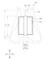
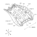
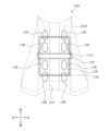
- FIG. 9 to 11 are diagrams showing the internal structure of the headrest 3 having the damper 50
- FIG. 9 is an exploded perspective view of the headrest frame 31
- FIG. 10 is a diagram showing the headrest frame 31 with the front cover 31a removed. It is.
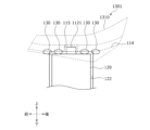
- FIG. 11 is a sectional view taken along line BB in FIG. 10, and is an explanatory diagram for explaining the positional relationship between the damper 50 and the connecting member 31c that supports the connector 31d.
- the headrest frame 31 includes a headrest pillar 30 that supports the headrest 3, and a front cover 31a and a rear cover 31b that cover the headrest pillar 30. Further, a headrest damper 53, which is a damper 50, is attached to the headrest pillar 30. A headrest speaker 43 and a microphone 67 are provided on the left and right sides of the headrest pillar 30. The headrest speaker 43 is rotatably attached to the headrest movable part 33. The headrest movable portion 33 is connected by a connecting member 31c. Although not shown, the headrest frame 31 is covered with a skin T.
- a harness and a connector 31d are attached to a connecting member 31c that connects the headrest speakers 43 and microphone 67 mounting members (headrest movable portion 33) arranged on the left and right sides.
- a harness and a connector 31d may be disposed between the connecting member 31c and the headrest damper 53.
- the harness and connector 31d By arranging the harness and connector 31d between the connecting member 31c and the headrest damper 53, it is possible to protect the harness and connector 31d from loads from the front and rear.
- an electroencephalogram detection section 62 is attached to the connecting member 31c.
- the connecting member 31c may be provided with not only the brain wave detection section 62 but also other biological detection sensors, pulse waves, and alertness sensors.
- the harnesses of the various sensors are arranged along the harnesses of the speaker 40 and the microphone 67. For example, like the harnesses for the headrest speaker 43 and the microphone 67, it may be placed through the inside of the headrest pillar 30.
- the brain wave detection unit 62 is arranged at a position avoiding the headrest pillar 30 and the headrest damper 53 when viewed from the front (occupant side), and close to the front cover 31a in front of the headrest pillar 30 and the headrest damper 53. Good.
- the headrest pillar 30 is bent into an inverted U-shape when viewed from the front, as shown in FIG.
- the headrest pillar 30 includes an upper portion 30a extending in the left-right direction, an upper pillar portion 30b extending downward from both left and right ends of the upper portion 30a, and an upper pillar portion 30b that is bent rearward from the lower end of the upper pillar portion 30b.
- a lower pillar portion 30c extends downward.
- the rear cover 31b of the headrest frame 31 is fixed to the headrest pillar 30 by the cover fixing part 32 extending forward holding the headrest pillar 30.
- the cover fixing part 32 is composed of an upper fixing part 32a provided on the upper side of the rear cover 31b and two lower fixing parts 32b provided on the lower side.
- the upper fixing part 32a holds the upper part 30a of the headrest pillar 30, and the lower fixing part 32b holds the lower pillar part 30c of the headrest pillar 30.
- the headrest damper 53 is attached to the headrest pillar 30. By providing the headrest damper 53 inside the headrest 3, the vibrations transmitted to the headrest 3 are transmitted to the headrest damper 53, and the headrest damper 53 resonates, making it possible to suppress the vibrations of the headrest 3. .
- the headrest damper 53 includes a weight 57, an elastic member 58 that covers the weight 57, a main body case 55 that houses the weight 57 and the elastic member 58, and a damper mounting portion that attaches the main body case 55 to the headrest pillar 30. 56.
- the weight 57 is elastically supported within the main body case 55 via an elastic member 58 so as to be able to vibrate.
- the weight 57 is made of metal (for example, cast iron), and is formed into a square prism shape in this embodiment.
- the elastic member 58 that elastically supports the weight 57 is a rectangular member formed in a sheet shape, and holds the weight 57 by sandwiching the weight 57 between the front, back, left, right, and top and bottom.
- the elastic member 58 is made of urethane foam material or rubber material formed to a desired thickness.
- the main body case 55 is divided into two parts in the front-rear direction, and includes a storage section 55a disposed on the front side and a lid section 55b disposed on the rear side.
- the storage portion 55a and the lid portion 55b are each made of synthetic resin.
- the main body case 55 is provided with a damper attachment portion 56 that connects to the headrest pillar 30.
- side attachment portions 56b are provided on both sides of the storage portion 55a of the main body case 55, and two upper attachment portions 56a are provided at the upper end of the storage portion 55a.
- the headrest damper 53 can be fixed to the headrest pillar 30 by holding the headrest pillar 30 with the curl-shaped holding part provided at the tip of the damper attachment part 56 .
- two upper mounting portions 56a extend from the upper surface of the main body case 55 to the upper portion 30a of the headrest pillar 30, and hold the upper portion 30a.
- the upper attachment part 56a is attached so as to avoid the upper fixation part 32a that fixes the rear cover 31b of the headrest frame 31.
- the upper fixing part 32a holds the center of the upper part 30a
- the two upper attaching parts 56a of the headrest damper 53 hold the upper part 30a so as to sandwich the upper fixing part 32a of the rear cover 31b.
- the side attachment portion 56b is provided to extend from the side surface of the main body case 55 to the upper pillar portion 30b of the headrest pillar 30 and to hold the upper pillar portion 30b.
- the ends of the upper attachment part 56a and the side attachment part 56b are formed in a curled shape, and the headrest damper 53 can be attached by fitting the headrest pillar 30 therein.
- the headrest damper 53 is preferably arranged at a position overlapping the headrest speaker 43 and the microphone 67 when viewed from the side (see FIG. 14). By arranging it in this way, it is possible to suppress the headrest 3 from increasing in size in the front-rear direction.
- the upper fixing part 32a of the rear cover 31b is sandwiched between the two upper mounting parts 56a and the upper part 30a is held, but this is just an example, and there is no other way. It may be configured as follows.
- the upper fixing part 321a for fixing the rear cover 31b and the upper mounting part 561a for attaching the headrest damper 531 may be arranged alternately.
- the upper fixing part 321a and the upper mounting part 561a may be arranged so as to be shifted in the left-right direction, and may be attached so as not to interfere with each other.
- the attachment of the damper attachment portion 56 and the upper fixing portion 321a is stabilized.
- the installation workability will be improved.
- one upper mounting part 562a extending from the headrest damper 532 holds the center of the upper part 30a, and two upper fixing parts 322a extending from the rear cover 312b hold the upper mounting part 562a. 562a may be avoided and the upper portion 30a of the headrest pillar 30 may be held.
- two upper mounting portions 563a extending from the headrest damper 533 may be attached to hold the bent portion 30d of the headrest pillar 30.
- the position of the upper mounting portion 563a can be regulated, and the number of damper mounting portions 56 can be reduced.
- one or both of the side attachment portions 56b provided in the headrest damper 53 shown in FIG. 11 can be omitted, making it possible to reduce the size of the damper attachment portion 56.
- the weight 57 of the headrest damper 53 which is a vibration reduction member, or the main body case 55 that houses it may be attached to the connecting member 31c in addition to the headrest pillar 30. Further, it may be attached to both the headrest pillar 30 and the connecting member 31c. Further, the lid portion 55b of the main body case 55 may be formed integrally with the connecting member 31c.
- the main body case 55 and the connecting member 31c of the headrest damper 53 are preferably made of resin, and by making them resin, they can be made lighter than if they were made of metal.
- the damper 50 which is a vibration suppressing member, is arranged inside the headrest 3; however, the location where the damper 50 is arranged is not limited to the inside of the headrest 3.
- Another example of the damper 50 disposed on the vehicle seat S will be described with reference to FIGS. 13 and 14.
- the damper 50 may be arranged inside the seat back 1 like a back damper 51 shown in FIG.
- the damper 50 is disposed at the upper or lower part of the seat back 1 between a pair of back speakers 41 that are spaced apart from each other in the seat width direction and are arranged on the left and right sides.
- a back damper 51 provided at the top of the seat back 1 is attached to the upper frame 12 or the pad P.
- a back damper 51 provided at the bottom of the seat back 1 is attached to the lower frame 13 or the pad P of the seat back 1.
- the back damper 51 is preferably placed behind the back speaker 41.
- the back damper 51 By arranging the back damper 51 near the pair of left and right back speakers 41, the effect of reducing vibration is improved, and the discomfort felt by the occupant H is suppressed.
- the damper 50 may be arranged inside the seat cushion 2 like a cushion damper 52 shown in FIG. Preferably, it is arranged at the front or rear part of the seat cushion 2 between a pair of cushion speakers 42 that are spaced apart from each other in the seat width direction and arranged on the left and right sides.
- a cushion damper 52 provided at the front of the seat cushion 2 is attached to the pan frame 22, the front connection frame 23, or the pad P.
- a cushion damper 52 provided at the rear of the seat cushion 2 is attached to the rear connection frame 24 or the pad P.
- the cushion damper 52 is preferably arranged below the cushion speaker 42, as shown in FIG. By arranging it near the cushion speakers 42 between the pair of left and right cushion speakers 42, the effect of reducing vibration is improved, and the discomfort felt by the occupant H is suppressed.
- the damper 50 may be placed inside the ottoman 4 like a damper 54 for an ottoman shown in FIG.
- the ottoman 4 it is arranged between ottoman speakers 44 that are spaced apart from each other in the seat width direction and are arranged on the left and right sides.
- the ottoman damper 54 is attached to the ottoman frame 35 or pad P of the ottoman 4.
- the ottoman damper 54 attached to the ottoman 4 may be placed at a position overlapping the ottoman speaker 44 when viewed from the side.
- the vehicle seat S is provided with a vibration detection section that detects vibration characteristics, and based on the detection results of the vibration detection section, the damper 50 is activated only when it is desired to reduce a predetermined vibration, for example, vibration that causes a large discomfort to the seated person. It may be activated.
- the sound system 100 of this embodiment is mounted on a vehicle
- the present invention is not limited to the sound system 100 mounted on a ground vehicle having wheels such as an automobile or a railway.
- the present invention may also be applied to an acoustic system 100 mounted on an aircraft, ship, or the like that travels outside the country.
- the second embodiment relates to a vehicle seat assembly, and particularly relates to a vehicle seat assembly including a seat and a battery.
- the present invention has been made in view of the above-mentioned problems, and its purpose is to provide a vehicle seat assembly in which the height of the seat can be suppressed even if a battery is provided below.
- the above problem can be solved by providing a seat on which an occupant sits, a battery disposed below the seat, and a battery supporting the battery between the seat and the battery.
- a recess is formed in the lower surface of the seat facing the battery, and at least a portion of the battery support member fits into the recess. Since the recess is formed in the lower surface of the seat, at least a portion of the battery support member that supports the battery fits into the recess. Therefore, even if the battery is provided below the seat, the position will not be raised high. Furthermore, since the height of the battery is not lowered, the battery capacity is prevented from becoming smaller.
- the battery support member is provided to extend in the seat front-rear direction or the seat width direction, and the recess formed in the lower surface of the seat is formed so that the battery support member extends. It is preferable that it be formed along the direction. Since a recess is formed in the lower surface of the seat in accordance with the direction in which the battery support member extends, the battery support member can be efficiently accommodated in the recess, and the seat can be prevented from becoming higher.
- a seat movable mechanism for changing the position of the seat is provided on the lower surface of the seat, and the seat movable mechanism avoids the recess formed in the seat. It would be good if it was placed in a suitable position. Since the seat movable mechanism is disposed at a position avoiding the recess, it is possible to suppress the seat from increasing in size, particularly in the height direction.
- a plurality of seat movable mechanisms for changing the position of the seat are provided on the lower surface of the seat, and the plurality of seat movable mechanisms move in the direction in which the recess extends. It would be better if they were placed along the same line.
- stable support by the seat movable mechanisms is enabled by arranging the plurality of seat movable mechanisms along the direction in which the recessed portions extend.
- the plurality of seat movable mechanisms may be arranged at symmetrical positions on the lower surface of the seat. By arranging the seat moving mechanisms in symmetrical positions, the seat can be moved stably.
- the seat movable mechanism may be an air cell that expands and contracts by supplying and discharging air. Since the seat moving mechanism is an air cell, the movement of the seat can be precisely controlled.
- a plurality of the air cells may be provided, and the plurality of air cells may be arranged at symmetrical positions on the lower surface of the seat. By arranging multiple air cells in symmetrical positions, the seat can be moved stably.
- the recess is preferably formed at the center of the lower surface of the seat in the width direction of the seat. By forming the recess at the center in the seat width direction, it is possible to improve the left-right balance of seat rigidity.
- the length of the recess in the longitudinal direction may be longer than the length of the battery support member in the longitudinal direction.
- the length of the recess in the transverse direction is preferably longer than the length of the battery support member in the transverse direction.
- the recess is formed in the lower surface of the seat, at least a portion of the battery support member that supports the battery fits into the recess. Therefore, even if the battery is provided below the seat, the position will not be raised high. Furthermore, since the height of the battery is not lowered, the battery capacity is prevented from becoming smaller. Further, since a recess is formed on the lower surface of the seat in accordance with the direction in which the battery support member extends, the battery support member can be efficiently accommodated in the recess, and the seat can be prevented from becoming higher.
- the seat movable mechanism is disposed at a position avoiding the recess, it is possible to suppress the seat from increasing in size, particularly in the height direction. Further, in addition to improving the rigidity due to the recess, stable support by the seat movable mechanisms is enabled by arranging the plurality of seat movable mechanisms along the direction in which the recesses extend. Furthermore, by arranging the seat moving mechanisms in symmetrical positions, the seat can be moved stably. Further, since the seat moving mechanism is an air cell, the movement of the seat can be precisely controlled. Furthermore, by arranging the plurality of air cells in symmetrical positions, the seat can be moved stably.
- the recess at the center in the width direction of the seat, it is possible to improve the left-right balance of seat rigidity. Moreover, by making the length of the recess in the longitudinal direction longer than the length of the battery support member in the longitudinal direction, it becomes easier to insert the battery support part into the recess. Moreover, by making the length of the recess in the width direction longer than the length of the battery support member in the width direction, it becomes easier to insert the battery support part into the recess.
- vehicle seat assembly an assembly of a vehicle seat and a battery (vehicle seat assembly) mounted on a two-wheeled vehicle
- vehicle seat assembly an assembly of a vehicle seat and a battery (vehicle seat assembly) mounted on a two-wheeled vehicle
- the "front-rear direction” refers to the front-rear direction of the two-wheeled vehicle seat, and is a direction that coincides with the direction in which the two-wheeled vehicle travels.
- the "seat width direction” is the width direction of the two-wheeled vehicle seat, and is a direction that coincides with the left-right direction as seen from the occupant seated on the seat.
- the "vertical direction” refers to the vertical direction of the two-wheeled vehicle seat, and is a direction that coincides with the vertical direction when the two-wheeled vehicle is traveling on a horizontal surface.
- the vehicle seat assembly 101 of this embodiment is comprised of a battery 120 placed below battery 110 and a battery support member 121 that supports battery 120.
- the vehicle seat 110 includes a bottom plate 111 serving as a base substrate on a vehicle body B, a cushioning material (not shown) placed on the bottom plate 111, and a skin material 113 covering the bottom plate 111 and the cushioning material. It is mainly composed of.
- the skin ends can be treated by attaching the engaging holes provided at the ends of the skin material 113 to the engaging claws 116 provided on the back surface of the bottom plate 111. A mounting method that does not use tacker needles or the like has been adopted.
- the bottom plate 111 is a long plate in the seat front-rear direction, and is a base substrate of the vehicle seat 110 that is curved to match the outer shape of the vehicle body B.
- the bottom plate 111 is formed as a synthetic resin molded product made of a resin material having a relatively high flexural modulus, such as glass fiber reinforced polypropylene (GFPP).
- GFPP glass fiber reinforced polypropylene
- the bottom plate 111 is preferably made of a relatively rigid resin material, but is not particularly limited and may be made of conventional raw materials such as polypropylene or polyethylene.
- a plurality of engaging pawls 116 are formed on the back surface of the outer circumferential portion of the bottom plate 111 at predetermined intervals over substantially the entire outer circumferential portion of the bottom plate 111 and protrude from the back surface.
- the cushion material is made of an elastic member made of urethane foam or the like, and is a cushion pad that is elongated in the front-rear direction of the seat, and is formed to be slightly larger than the outer shape of the bottom plate 111.
- the skin material 113 is a covering material that constitutes the appearance of the vehicle seat 110, and includes a front skin material 113a and a back skin material 113b attached to the end portion of the front skin material 113a. It is equipped with
- the front skin material 113a is made of a covering material using polyvinyl chloride leather or the like. To be more specific, the front skin material 113a is formed by pasting a soft polyvinyl chloride layer on the surface of a fabric such as knitted material. ing.
- the back skin material 113b is made of a covering material with lower elasticity than the front skin material 113a, and is made of a mesh-like fabric such as Queen's coat, for example.
- the back side skin material 113b is formed by bonding a soft polyvinyl chloride layer to the surface of a fabric such as knitted fabric.
- the skin material 113 is made of polyvinyl chloride leather or the like as the material for the front skin material 113a, making it suitable as a skin material for motorcycles that are directly exposed to wind and rain.
- the back side skin material 113b from a mesh-like material, it is possible to reduce the weight of the skin material and improve drainage performance and air permeability.
- a battery housing section 122 is provided below the vehicle seat 110, and a replaceable battery 120 is housed in the battery housing section 122.
- a replaceable battery 120 is housed in the battery housing section 122.
- a battery support member 121 for fixing the battery 120 to the battery accommodating portion 122 is provided on the top surface of the battery 120.
- the battery support member 121 not only fixes the battery 120 to the battery housing part 122, but also may be used as a handle when replacing the battery.
- the vehicle user When replacing the battery 120, the vehicle user (occupant) raises the vehicle seat 110, releases the fixation of the battery, lifts the battery support member 121 provided on the battery, and takes it out from the battery storage section 122. After replacing the battery 120, a new battery is inserted into the battery housing section 122 and fixed by the battery support member 121.
- the battery 120 becomes larger and is replaced frequently, so the battery support member 121 and the like also become larger, and battery-related members such as the battery support member 121 are placed below the vehicle seat. Because of this, the position of the vehicle seat tends to be higher than that of conventional seats.
- the vehicle seat 110 of the present embodiment has a first recess 114 extending in the front-back direction of the seat formed on the surface facing the battery 120, more specifically, on the lower surface of the bottom plate 111 as shown in FIG. As shown in FIGS. 16 and 17, the first recess 114 is configured to accommodate at least a portion of the battery support member 121.
- the vehicle seat 114 is A first recess 114 formed on the lower surface of the recess 114 is also formed to extend in the front-rear direction in accordance with that direction. This allows easy insertion. Further, the first recess 114 is formed at a substantially central position in the sheet width direction. By forming the first recess 114 at a substantially central position, it is possible to improve the left-right balance of seat rigidity.
- the length L1 (length in the front-rear direction) of the first recess 114 in the longitudinal direction is longer than the length L2 of the battery support member 121 in the longitudinal direction.
- the length W1 of the first recess 114 in the width direction is longer than the length W2 of the battery support member 121 in the width direction (seat width direction). It is formed.
- FIGS. 19 to 21 A second example of the second embodiment will be described using FIGS. 19 to 21.
- the direction in which the battery support member 121 extends is not limited to the longitudinal direction of the vehicle seat.
- the battery support member 1121 may be provided to extend along the width direction of the seat.
- the battery support member 1121 When the battery support member 1121 is provided along the seat width direction, as shown in FIG. It is formed to be longer than the length L102 in the longitudinal direction (sheet width direction, left and right direction). When the battery support member 121 is provided along the seat width direction, as shown in FIG. It is formed to be longer than the length W102 in the transverse direction (seat front and back direction). By forming in this way, it becomes easy to insert the battery support member 1121 into the second recess 115. In the embodiment shown in FIGS. 19 to 22, the first recess 114 extending in the front-rear direction is also formed, but the recess may be formed only in the seat width direction. Strength can be improved by combining the first recess 114 extending in the front-rear direction and the second recess 115 extending in the seat width direction.
- a vehicle seat assembly 1201 according to a third embodiment will be described with reference to FIGS. 22 to 24.
- the vehicle seat assembly 1201 of the third embodiment is an assembly consisting of a vehicle seat 1210 and a battery 120, and a battery support member to which the battery 120 is attached is provided between the vehicle seat 1210 and the battery 120. 121 is provided. Further, a plurality of air cells 130 are provided between the vehicle seat 1210 and the battery 120.
- the air cell 130 functions as a seat moving mechanism that changes the position of the vehicle seat 1210.
- a pipe (not shown) for feeding air is connected to the air cell 130, and it expands and contracts by supplying and discharging air, thereby making it possible to adjust the position of the vehicle seat 1210. ing.
- the other configurations are the same as those of the vehicle seat assembly 101 of the first embodiment and the vehicle seat assembly 1101 of the second embodiment, so the same reference numerals are given and detailed explanation thereof will be omitted.
- a first recess 114 is formed in the lower surface of the vehicle seat 1210.
- the air cell 130 which is a seat movable mechanism, is arranged at a position avoiding this first recess 114. That is, the air cell 130 is arranged at a position on the lower surface of the vehicle seat 1210 where the first recess 114 is not formed. With this arrangement, the air cell 130 does not overlap the battery support member 121 in the vertical direction, and it is possible to suppress the vehicle seat 1210 from increasing in size, particularly in the height direction.
- the plurality of air cells 130 are arranged side by side along the direction in which the first recess 114 extends (front-back direction). This arrangement allows stable support by the air cell 130. Further, the air cells 130 are arranged at symmetrical positions on the lower surface of the vehicle seat 1210 with the first recess 114 in between. By arranging the air cells 130 in symmetrical positions, the vehicle seat 1210 can be moved stably. In the example shown in FIG. 24, three air cells 130 are arranged in two rows in parallel in the front-rear direction, but this is just an example, and three or more air cells 130 may be arranged in parallel. The above may be provided in parallel. Moreover, providing the air cell 130 as a seat movable mechanism is only an example, and is not limited to this. For example, instead of the air cell 130, a structure for mechanically changing the position may be provided. By using the air cell 130, the position of the vehicle seat 1210 can be precisely controlled.
- a vehicle seat assembly 1301 according to a fourth embodiment will be described with reference to FIGS. 25 to 27.
- the vehicle seat assembly 1301 of the fourth embodiment is an assembly consisting of a vehicle seat 1310 and a battery 120, and a battery support extending in the width direction of the seat is provided between the vehicle seat 1310 and the battery 120.
- a member 1121 is provided.
- a plurality of air cells 130 which are seat movable mechanisms, are arranged in line between the vehicle seat 1310 and the battery 120.
- a first recess 114 extending in the front-back direction and a second recess 115 extending in the seat width direction are formed on the lower surface of the vehicle seat 1310.
- a battery support member 1121 is configured to be housed in the recess 115 . Since the other configurations are the same as those of the vehicle seat assemblies 101, 1101, and 1201 of the first to third embodiments, the same reference numerals are given and the explanation thereof will be omitted.
- the air cell 130 is arranged on the lower surface of the vehicle seat 1310 at a position avoiding the first recess 114 and the second recess 115. That is, the air cell 130 is arranged on the lower surface of the vehicle seat 1310 at a position where the first recess 114 and the second recess 115 are not formed. Thereby, the seat does not overlap with the battery support member 1121 in the vertical direction, and it is possible to suppress the sheet from increasing in size, particularly in the height direction. Further, the plurality of air cells 130 are arranged side by side along the direction in which the first recess 114 extends (front-back direction). This arrangement allows stable support by the air cell 130. Further, in the example shown in FIG.
- the air cells 130 are arranged at symmetrical positions on the lower surface of the vehicle seat 1310 with the first recess 114 in between. Furthermore, two rows of four air cells 130 are provided in parallel in the front-rear direction. By arranging a plurality of air cells 130 in symmetrical positions in this manner, the vehicle seat 1310 can be moved stably.
- the second embodiment of the present invention has been described above using the figures.
- the vehicle seat assembly of the second embodiment is mounted on a two-wheeled vehicle
- the present invention is not limited to a vehicle seat assembly for a two-wheeled vehicle.
- the vehicle seat assembly may be a vehicle seat assembly for a four-wheeled or three-wheeled vehicle mounted on a ground traveling vehicle having wheels such as an automobile or a railway.
- the seat assembly may be a vehicle seat assembly mounted on an aircraft, a ship, or the like that moves on a place other than the ground.
- the third embodiment relates to an electric vehicle and a vehicle seat, and particularly relates to a rotating machine that transmits torque to wheels, a vehicle interior component provided in a vehicle seat or a vehicle door, and a control that controls the rotating machine.
- the present invention relates to an electric vehicle and a vehicle seat, which includes a parts control part for controlling the vehicle interior parts, and does not include an engine, a transmission, and a clutch mechanism connected to the engine.
- the electric vehicle described in Japanese Patent No. 6787507 and Japanese Patent Application Publication No. 2020-156260 includes a simulated clutch pedal for simulating the operation of the clutch mechanism, a simulated shift lever for simulating the operation of the transmission, and a rotating machine.
- the torque control unit controls the torque of the rotating machine based on the operation of the simulated clutch pedal and the simulated shift lever, so that the driver can control the torque of the MT. It gives the feeling of driving a car.
- the present invention has been made in view of the above problems, and an object of the present invention is to provide an electric vehicle and a vehicle seat that can improve occupant comfort and entertainment in MT mode.
- the above problem is solved by: a rotating machine that transmits torque to wheels; a vehicle interior component provided on a vehicle seat or a vehicle door; a control unit that controls the rotating machine; A parts control unit that controls vehicle interior parts, and does not include an engine and a transmission and clutch mechanism connected to the engine, the control unit controlling a manual transmission according to an operation by a passenger. a mode switching unit that switches between a manual mode for controlling the rotating machine to simulate the above, and a normal mode for controlling the rotating machine in a manner different from the manual mode; The problem is solved by controlling the vehicle interior parts when the mode switching unit switches to the manual mode.
- the vehicle interior parts installed in the vehicle seat or vehicle door are controlled to simulate a MT car, allowing the driver to drive with a feeling similar to the manual gear shifting operation of an MT car. can do. Therefore, comfort and entertainment for the occupants in the MT mode can be improved.
- the vehicle interior component includes a movable body that is attached to the inside of the vehicle seat and operates to project a part of the vehicle seat toward the seated person from a normal position, and
- the unit may control the movable body when the mode switching unit switches to the manual mode.
- the component control section may change the amount of protrusion of the movable body when a predetermined condition is satisfied in the manual mode.
- the amount of protrusion of the movable body changes depending on predetermined conditions (for example, changes in vehicle speed, road conditions, etc.), so the occupant tends to feel restrained due to the movable body changing depending on the situation. Therefore, the safety, feeling, and entertainment for the occupants in the MT mode can be further improved.
- the vehicle interior component is a seat belt device provided on the vehicle seat, and the seat belt device includes a seat belt that restrains the occupant and a belt retractor that retracts the seat belt so that it can be pulled out.
- the parts control section may control the belt retractor when the mode switching section switches to the manual mode.
- the vehicle seat includes a seat body including a seat cushion and a seat back, and a rail device that supports the seat body so as to be movable back and forth with respect to the vehicle floor, or the seat back is connected to the seat cushion.
- a reclining device rotatably connected, and the component control section may control the rail device or the reclining device when switched to the manual mode by the mode switching section.
- the mode switching unit is capable of switching between the manual mode, the normal mode, and an automatic driving mode capable of automatic driving, and the seat when switched to the manual mode by the mode switching unit
- the amount of movement of the seat body or the seat back when switched to the automatic driving mode may be more limited than the amount of movement of the main body or the seat back.
- the control unit includes an identification information acquisition unit that acquires identification information of the occupant, a mode setting unit that sets the mode according to the operation of the occupant, and a mode setting unit that sets the mode according to the operation of the occupant. and a storage unit that stores the information in association with the identification information of the occupant, and the mode switching unit may switch the mode based on the mode associated with the identification information of the occupant.
- the storage unit stores restriction information that restricts the passenger from driving the manual transmission vehicle in association with the identification information of the passenger, and the mode switching unit stores the restriction information in the storage unit.
- Switching to the manual mode may be restricted when the mode is set.
- switching to MT mode is restricted by the restriction information that restricts passengers from driving MT cars, so passengers who do not have a license that allows them to drive MT cars end up driving in MT mode. can be suppressed.
- the electric vehicle includes a fellow passenger detection section that detects a fellow passenger different from the passenger, and the mode switching section is configured to switch the mode switching section when the fellow passenger is detected by the fellow passenger detection section. You may be restricted from switching to the mode. With the above configuration, switching to the MT mode is restricted depending on the presence or absence of a fellow passenger, thereby further improving safety when a fellow passenger is in the vehicle.
- the vehicle seat of the present invention which is installed in an electric vehicle that is equipped with a rotating machine that transmits torque to the wheels and is not equipped with an engine, a transmission connected to the engine, and a clutch mechanism.
- the vehicle seat includes a seat body, a vehicle interior component provided in the seat body, a component control unit that controls the vehicle interior component, and a manual transmission that simulates a manual transmission in response to an operation by an occupant.
- an acquisition unit that acquires a switching signal for switching between a manual mode in which the rotating machine is controlled in such a manner as to be controlled, and a normal mode in which the rotating machine is not controlled so as to simulate a manual transmission;
- the problem is solved by controlling the vehicle interior parts when the acquisition unit acquires the switching signal.
- the vehicle interior parts provided on the vehicle seat and the vehicle door are controlled, making it easier for the occupants to enjoy the ride.
- the vehicle interior parts installed on the vehicle seat or vehicle door are controlled to simulate a MT vehicle, allowing the driver to drive with a feeling similar to the manual gear shifting operation of an MT vehicle. can do. Therefore, comfort and entertainment for the occupants in the MT mode can be improved.
- ⁇ Effects of the invention> it is possible to improve passenger comfort and entertainment in the MT mode. Further, it is possible to further improve the safety, feeling, and entertainment for the occupants in the MT mode. Furthermore, the safety, feeling, and entertainment for the occupants in the MT mode can be further improved. Further, it is possible to further improve passenger comfort and entertainment in the MT mode. Furthermore, depending on the mode, it is possible to give the occupant a sense of restraint or freedom. Further, the convenience for the occupant in the MT mode can be improved. Furthermore, it is possible to prevent an occupant who does not have a license that allows him to drive a manual transmission vehicle from driving in manual transmission mode. Furthermore, safety can be improved when a fellow passenger is riding the vehicle.
- the "front and rear direction” means the front and rear direction as seen from the occupant of the vehicle seat S200 (hereinafter sometimes referred to as a seated person), as shown in FIG.
- the direction is the same as the direction.
- the "seat width direction” is the width direction of the vehicle seat S200, and corresponds to the left-right direction when viewed from the occupant of the vehicle seat S200.
- the "vertical direction” is the vertical direction of the vehicle, as shown in FIG. 28, and is a direction that coincides with the vertical direction when the vehicle is traveling on a horizontal plane.
- the electric vehicle 201 of this embodiment is, for example, a four-wheeled electric vehicle (EV vehicle) capable of self-driving, and is disposed in a vehicle body B200 and an internal space of the vehicle body B200, in which a passenger is seated.
- the vehicle seat S200 includes a vehicle seat S200, which is arranged to partition an internal space and an external space of a vehicle body B200, and a vehicle door D200 through which a passenger gets on and off the vehicle.
- the electric vehicle 201 is an ordinary passenger car as an example, but the present invention is applicable to any type of vehicle such as a wagon or an SUV (Sport Utility Vehicle).
- the vehicle is not limited to an EV vehicle that can be driven automatically, but may be an EV vehicle that is not capable of automatically driven. Furthermore, the vehicle is not limited to a four-wheeled self-driving vehicle, and may be a three-wheeled vehicle (two front wheels, one rear wheel).
- the electric vehicle 201 is an electric vehicle that does not include an engine, a transmission, and a clutch mechanism connected to the engine, and includes a rotating machine 202 that transmits torque to wheels, and a rotating machine 202 that transmits electric power to the rotating machine 202. and a battery 203 for driving the vehicle. Furthermore, the electric vehicle 201 is not equipped with a mechanical manual transmission and runs by rotating a rotary machine 202 using electric power. A simulated clutch device 205 for simulating.
- the electric vehicle 201 includes a touch panel 206 that can be operated by a passenger, an exterior camera 207 that photographs the surroundings of the vehicle body B200, an interior camera 208 that photographs the inside of the vehicle body B200, and a vehicle speed sensor 209 that detects vehicle speed. Be prepared.
- the electric vehicle 201 can be switched between a manual driving mode in which the driver performs driving operations and an automatic driving mode in which the driver does not require driving operations, as a driving mode, for example, according to an operation by a passenger. Furthermore, the electric vehicle 201 has two manual driving modes: a manual mode (hereinafter referred to as MT mode) in which the rotating machine 202 is controlled to simulate a manual transmission according to the operation of the occupant; It is possible to switch to a normal mode (hereinafter referred to as EV mode) of the electric vehicle 201 in which the electric vehicle 201 is controlled.
- MT mode manual mode
- EV mode normal mode
- the electric vehicle 201 can be switched to MT mode, EV mode, and automatic driving mode as driving modes.
- the occupant can switch between each mode by selecting the driving mode using the touch panel 206.
- the MT mode is a driving mode in which the torque characteristics of the electric vehicle 201 are changed according to the operation of the simulated shift device 204 and the simulated clutch device 205 so as to simulate a manual transmission.
- the EV mode is a driving mode in which the torque characteristics of the electric vehicle 201 are automatically changed, like an automatic transmission vehicle, regardless of the operation of the simulated shift device 204 and the simulated clutch device 205.
- the automatic driving mode is a driving mode in which the situation of the electric vehicle 201 is determined based on signals output by various sensors and signals input by the occupant, and the electric vehicle 201 is driven autonomously according to the determination result.
- the rotating machine 202 is provided on the front side of the vehicle body B200, and includes a travel motor 202a that is, for example, a three-phase AC motor.
- the output shaft of the travel motor 202a is connected to the front wheels via a shaft.
- Travel motor 202a is controlled by motor ECU 2110, which will be described later, based on an instruction torque transmitted from ECU 2100, which will be described later.
- the battery 203 is disposed below the vehicle floor F200 and stores electrical energy used to drive the rotating machine 202.
- the simulated shift device 204 includes a simulated shift lever 204a for selecting a shift position, a vibration applying section 204b for applying vibration to the driver, and a shift lever sensor 204c for detecting the shift position.
- the simulated shift lever 204a is provided near the driver's seat of the electric vehicle 201 at a position that can be operated by the driver, and has a shape similar to that provided in a general manual transmission vehicle (MT vehicle).
- MT vehicle general manual transmission vehicle
- the simulated shift lever 204a is an operation unit for selecting one shift position corresponding to a plurality of virtual gear stages having different torque characteristics in the MT mode.
- the shift positions include, for example, a forward range of 1st, 2nd, 3rd, 4th, and 5th speeds, and a reverse range for reverse.
- the torque characteristic of each virtual gear stage is preset to a torque characteristic that simulates the gear stage of a manual transmission vehicle.
- the shift position selected by the driver using simulated shift lever 204a is detected by shift lever sensor 204c and transmitted to ECU 2100.
- the vibration applying unit 204b generates vibrations that can be sensed by the driver in order to notify the driver of various information. For example, the vibration applying unit 204b notifies the driver that the simulated shift lever 204a can be operated when shifting to the MT mode, or changes the torque characteristics to give the driver the feeling of operating an MT vehicle. It vibrates accordingly.
- the simulated clutch device 205 includes a simulated clutch pedal 205a for selecting a shift position, a resistance force applying part 205b for making the simulated clutch pedal 205a approximate the operating feel of a manual transmission vehicle, and detects the amount of depression of the simulated clutch pedal 205a. It has a pedal sensor 205c for.
- the simulated clutch pedal 205a is provided in the vicinity of the driver's seat of the electric vehicle 201 at a position where it can be depressed and operated, and has a shape similar to that provided in a typical manual transmission vehicle.
- the simulated clutch pedal 205a is depressed when the driver operates the simulated shift lever 204a, and is used to simulate the feeling of driving in the MT mode.
- the amount of depression of the simulated clutch pedal 205a is detected by the pedal sensor 205c and transmitted to the ECU 2100.
- the resistance force applying unit 205b generates a resistance force in the direction of returning the simulated clutch pedal 205a in response to the operation of the simulated clutch pedal 205a.
- the resistance force applying unit 205b applies a resistance force in accordance with changes in torque characteristics, for example, in order to give the driver the feeling of operating a manual transmission vehicle.
- the touch panel 206 is provided on the front side (for example, on the instrument panel) of the vehicle body B200 of the electric vehicle 201 at a position that can be operated by a passenger.
- the touch panel 206 is capable of inputting operations by the occupant, and also functions as a display device that displays information to the occupant.
- the touch panel 206 is used, for example, to set and select the driving mode, to set the torque of the rotary machine 202 in the MT mode, to set the vehicle seat S200 and the vehicle door D200 in the MT mode, to select the range in the EV mode, and to select the range in the automatic driving mode. Used for input operations such as setting a destination. Information input to touch panel 206 is transmitted to ECU 2100.
- touch panel 206 displays, for example, a setting and selection screen for the occupant, information for the occupant, images acquired from the vehicle exterior camera 207 or the vehicle interior camera 208, and the like.
- the content displayed on touch panel 206 is controlled by ECU 2100.
- the vehicle exterior camera 207 is provided outside the vehicle body B200 of the electric vehicle 201 (for example, on the roof) at a position where it can photograph the surroundings of the electric vehicle 201.
- the electric vehicle 201 can determine the state of the surroundings of the electric vehicle 201 based on image information captured by the camera 207 outside the vehicle. For example, by photographing the surroundings of the electric vehicle 201, it is possible to detect other vehicles traveling nearby or to detect whether the road is highly dangerous, such as a series of curves.
- Information photographed by the vehicle exterior camera 207 is transmitted to the ECU 2100 as photographed data.
- the in-vehicle camera 208 is provided on the front side (for example, on the instrument panel) inside the vehicle body B200 of the electric vehicle 201 at a position where it can photograph the occupants (driver and fellow passengers).
- the electric vehicle 201 can determine the condition of the occupant based on image information captured by the in-vehicle camera 208. For example, by photographing the driver's face, the driver's identification information (driver ID) can be recognized. Furthermore, by photographing the occupant, it is possible to detect that the driver or fellow passenger is seated on the vehicle seat S200.
- the in-vehicle camera 208 has a function as a seating sensor or a passenger detection sensor. Information captured by in-vehicle camera 208 is transmitted to ECU 2100 as captured data.
- the vehicle speed sensor 209 is provided within the vehicle body B200, as shown in FIG. 28, and detects the traveling speed of the electric vehicle 201. Based on the detected value of the vehicle speed sensor 209, the electric vehicle 201 can determine whether or not it is traveling or whether it is traveling at high speed. Information detected by vehicle speed sensor 209 is transmitted to ECU 2100 as vehicle speed data.
- the vehicle seat S200 is installed in the vehicle body B200, and includes a seat body including a seat cushion 210, a seat back 220, and a headrest 230, and the seat body is movable back and forth with respect to the vehicle body floor F200.
- a reclining device 250 that rotatably connects the seat back 220 to the seat cushion 210;
- a seat movable device 260 that operates to protrude a portion of the seat back 220;
- the vehicle includes a seatbelt device 270 that is attached to the inside of the vehicle 220 to restrain the upper body of a seated person, and a seat notification device 280 that notifies the occupant of various information.
- the seat cushion 210 is a seating portion that supports the occupant from below, and is configured by placing a pad material 210a on a cushion frame serving as a skeleton and covering the cushion frame with a skin material 210b.
- the seat back 220 is a backrest portion that supports the back of the occupant from behind, and is configured by placing a pad material 220a on a back frame 221 serving as a skeleton and covering it with a skin material 220b.
- the seat back 220 includes a center portion 220A located at the center in the seat width direction, and left and right side portions 220B (side bolster portions) located outside the center portion 220A in the seat width direction. , is composed of.
- the rail device 240 is an electric device that moves the seat body back and forth with respect to the vehicle body floor F200.
- the rail device 240 includes a lower rail 241 that extends in the front-rear direction and is fixed to the vehicle body floor F200, an upper rail 242 that extends in the front-rear direction and is fixed to the seat cushion 210, and a rail drive that moves the upper rail 242 in the front-rear direction with respect to the lower rail 241. It has a motor 243.
- the rail drive motor 243 is driven by the occupant operating a switch (not shown) or by the seat ECU 2120 (described later) receiving a control signal, and the seat body is moved toward the vehicle floor. Move back and forth relative to F200.
- the reclining device 250 is an electric device that tilts the seat back 220 with respect to the seat cushion 210, as shown in FIG.
- the reclining device 250 is attached to the left side in the seat width direction, and includes a rotation motor 251 that tilts the seat back 220 at a predetermined angle.
- the rotation motor 251 is driven by the occupant operating a switch (not shown) or by the seat ECU 2120 receiving a control signal, and the seat back 220 is moved toward the seat cushion 210. tilted forward and backward.
- the seat moving device 260 is an electric device that operates to protrude the side portion 220B of the seat back 220, as shown in FIGS. 29 to 31.
- the seat movable device 260 is a movable body having, for example, an air cell, and when compressed air is sealed in the seat movable device 260, the seat movable device 260 bulges toward the passenger (seated person) and protrudes from the normal position to the protruding position. The seat movable device 260 then contracts as the enclosed compressed air is discharged and returns to its normal position.
- the seat movable device 260 is a side support member that supports the seated person from the side, and is disposed between the pad material 220a and the back frame 221 in the side portion 220B of the lower portion of the seat back 220. .
- the seat moving device 260 is attached to the front surface of the back frame 221 in a folded state. The seat moving device 260 operates to project the pad material 220a of the side portion 220B toward the seated person.
- the seat movable device 260 has a substantially pentagonal shape that is elongated in the vertical direction, and includes a base member 261 supported by the back frame 221 and a position in front of the seat relative to the base member 261.
- a rotating member 263 is attached so as to be rotatable via a rotating shaft 262, and a plurality of bags are disposed between the base member 261 and the rotating member 263 and supported on the front surface of the base member 261.
- 264, and an air supply section 265 that is attached inside the seat body and supplies compressed air to the bag body 264.
- the base member 261 is attached to the front surface of the back frame 221 and extends along the front surface of the back frame 221 so as to protrude in the seat width direction.
- the rotation shaft 262 is attached to the inner end of the front surface of the base member 261 in the seat width direction.
- the rotating member 263 is attached to the base member 261 so as to be rotatable in the front-rear direction of the seat, and by rotating toward the front of the seat, causes the side portion 220B of the seat back 220 to protrude toward the front of the seat. , can be pushed out.
- the rotating member 263 is a plate body having a curved shape slightly curved toward the front of the seat. Therefore, the contact area between the rotating member 263 and the pad material 220a becomes somewhat small, and the pushing force of the rotating member 263 is efficiently transmitted to the pad material 220a.
- the rotating member 263 is arranged at a position closer to the base member 261 when the seat back 220 is in the normal position. Further, the rotating member 263 may be biased toward the base member 261 by a biasing spring (biasing member) not shown.
- the plurality of bags 264 are supported by the base member 261, and when filled with compressed air, they bulge toward the front of the seat and can push the rotating member 263 toward the front of the seat. That is, the rotating member 263 can be rotated forward of the seat.
- the plurality of bags 264 are arranged at different positions in the seat front-rear direction and the seat width direction, and have different sizes. Specifically, the plurality of bags 264 are composed of three air cells, and among the plurality of bags 264, the first bag 264a located closest to the front of the seat has the smallest capacity than the other air cells. has been done. The second bag 264b has the largest capacity, and the third bag 264c has a medium capacity.
- the direction and amount of protrusion of the side portion 220B of the seat back 220 can be adjusted by inflating the plurality of bags 264 having different positions and sizes. Furthermore, by adjusting the direction and amount of protrusion of the side portions 220B of the seat back 220, it is possible to suppress wrinkles and bagging in the skin material 220b of the seat back 220.
- the air supply section 265 is attached inside the seat body and supplies compressed air to the bag body 264.
- the air supply section 265 supplies compressed air to the bag body 264 and discharges the compressed air from the bag body 264 using an air pump.
- the air supply unit 265 is driven and the bag body 264 is moved by the occupant operating a switch (not shown) or by the seat ECU 2120 (described later) receiving a control signal. The range is adjusted.
- the seat moving device 260 can bulge out so as to move the side portion 220B of the seat back 220 from the "normal position” shown in FIG. 30 to the "protruding position” shown in FIG. 31.
- the seat movable device 260 is disposed between the back frame 221 and the skin material 220b in the seat longitudinal direction.
- the seat movable device 260 is attached to the front surface of the back frame 221 and arranged on the back surface of the pad material 220a.
- the folded bag body 264 expands and unfolds toward the front of the seat, and pushes the rotary member 263 toward the front of the seat, thereby causing the side portion 220B moves to the front of the seat.
- the side portion 220B moves to the "protruding position”.
- the compressed air inside the bag body 264 is discharged by the air supply unit 265, so that the inflated bag body 264 is deflated, and the side portion 220B is lowered toward the rear of the seat.
- the side portion 220B of the seat back 220 returns from the "protruding position" to the "normal position".
- the seat movable device 260 is attached to the seat back 220, but the seat movable device 260 may be attached to the seat cushion 210 without particular limitation. Further, the seat movable device 260 may be configured to operate by a mechanical mechanism (such as a link mechanism or a hinge mechanism). Note that the air supply section 265 may be configured by a motor type or hydraulic type drive device.
- the seat belt device 270 includes a seat belt 271 that restrains the upper body of a seated person, a belt guide 272 provided at the upper right end of the seat back 220 for guiding the seat belt 271, and a rail.
- the belt buckle 273 is provided on the device 240 and is detachably connected to the seat belt 271, and the belt retractor 274 is attached to the back frame 221 and retracts the seat belt 271 so that the seat belt 271 can be pulled out.
- the seat belt 271 extends vertically along the shoulder of the occupant and restrains the right shoulder of the occupant to the seat back 220 .
- the belt guide 272 is attached to a position above the belt retractor 274 on the right side of the seat back 220, and guides the seat belt 271 pulled out from the belt retractor 274 toward the belt buckle 273 on the lower left.
- the belt buckle 273 is provided on the left outer surface of the rail device 240 and is detachably connected to a belt tongue plate (not shown) attached to the tip of the seat belt 271.
- the belt retractor 274 is a winding device that winds up the upper end of the seat belt 271.
- the belt retractor 274 has a winding motor 274a for winding up the seat belt 271.
- the winding motor 274a is driven by the occupant operating a switch (not shown), or by the seat ECU 2120 (to be described later) receiving a control signal, and the winding motor 274a is driven. The feeling of restraint is adjusted.
- the seat notification device 280 is a device that is provided in the vehicle seat S200 and notifies the occupant of a message or the like.
- the sheet notification device 280 includes a sound output device 281 that outputs sound, and a light emitting device 282 that includes a plurality of LED elements.
- the sound output device 281 is a speaker that is provided on the headrest 230 and outputs sounds such as a beep sound, an alarm sound, a voice message, and music.
- the sound output device 281 can notify the occupant seated on the seat cushion 210 of various information when the seat ECU 2120 receives a control signal.
- the light emitting device 282 is a lighting device that is provided on the seat back 220 and the headrest 230 and emits light inside the vehicle.
- the light emitting device 282 can notify the occupant of various information by controlling the light emission of each LED element and its timing when the seat ECU 2120 receives a control signal.
- the vehicle door D200 is constructed by covering a door lining base material serving as a substrate with a door skin material.
- the vehicle door D200 includes a door notification device 290 that notifies the occupant of various information.
- the door notification device 290 is a device that is provided on the vehicle door D200 and notifies the occupant of a message or the like.
- the door notification device 290 includes a door sound output device 291 that outputs sound, and a door light emitting device 292 that includes a plurality of LED elements.
- the door sound output device 291 is a speaker that is provided at the center of the vehicle door D200 on the inside of the vehicle and outputs sounds such as a beep sound, an alarm sound, a voice message, and music.
- the door sound output device 291 can notify the occupant seated on the seat cushion 210 of various information when a door ECU 2130 (described later) receives a control signal.
- the door light emitting device 292 is a lighting device that is provided at the upper part of the vehicle door D200 on the inside of the vehicle and emits light inside the vehicle.
- the door light emitting device 292 can notify the occupant of various information by controlling the light emission of each LED element and its timing when the door ECU 2130 receives a control signal.
- the electric vehicle 201 includes an ECU 2100 that controls the running of the vehicle, and a motor ECU 2110, a seat ECU 2120, and a door ECU 2130 as lower ECUs of the ECU 2100.
- Each ECU has a control circuit and is mainly composed of a central processing unit (CPU), ROM (Read Only Memory) as a storage device, RAM (Random Access Memory), HDD (Hard Disk Drive), etc. has been done.
- CPU central processing unit
- ROM Read Only Memory
- RAM Random Access Memory
- HDD Hard Disk Drive
- the CPU is a central processing unit that executes various programs and controls various parts. That is, the CPU reads a program from the ROM or HDD and executes the program using the RAM as a work area. The CPU controls each component and executes various calculation processes according to programs stored in the ROM and HDD.
- the ROM stores various programs and various data.
- the RAM temporarily stores programs or data as a work area.
- the HDD may be an SSD (Solid State Drive), and stores various programs including an operating system and various data.
- the ECU 2100 of this embodiment incorporates a control circuit that performs torque control that determines a torque value to be instructed to the rotating machine 202.
- ECU 2100 is connected to rotating machine 202, battery 203, simulated shift device 204, simulated clutch device 205, touch panel 206, exterior camera 207, interior camera 208, and vehicle speed sensor 209.
- Each component is communicably connected to each other via a bus.
- the electric vehicle 201 may be equipped with various actuators, input devices, output devices, and various sensors in addition to these.
- the ECU 2100 uses a known technique that simulates a manual transmission, and controls the driving torque of the rotating machine 202. In controlling the torque of the rotating machine 202, the ECU 2100 performs calculations on the assumption that the running state of the electric vehicle 201 is realized by a manual transmission vehicle equipped with a virtual engine and transmission. Motor ECU 2110 controls travel motor 202a based on the command torque transmitted from ECU 2100.
- the ECU 2100 can notify the driver of various information and provide the driver with the feeling of operating an MT vehicle using the lever pedal control unit 2102, which will be described later. Furthermore, when electric vehicle 201 is in MT mode, ECU 2100 transmits various information to seat ECU 2120 and door ECU 2130. The seat ECU 2120 and the door ECU 2130 can notify the driver of various information and provide the driver with the feeling of operating a manual transmission vehicle.
- the ECU 2100 controls the electric vehicle 201 by determining the surrounding situation of the electric vehicle 201 and the situation of the electric vehicle 201 itself.
- the ECU 2100 determines the surrounding situation of the electric vehicle 201 based on input information on the touch panel 206 and information obtained from the external camera 207 and the vehicle speed sensor 209 in order to cause the electric vehicle 201 to run autonomously.
- the situation of the electric vehicle 201 itself is determined.
- the ECU 2100 performs automatic driving control processing to control accelerator, brake, and steering wheel operations according to the determination result.
- torque control that simulates a manual transmission when the electric vehicle 201 is in the automatic driving mode, torque control that simulates a manual transmission is not performed.
- the present invention is not limited to this, and torque control that simulates a manual transmission may be performed even when the electric vehicle 201 is in the automatic driving mode. Note that when performing torque control that simulates a manual transmission, the torque control amount may be more limited than in the MT mode.
- each ECU is realized by the cooperation of hardware devices (specifically, a CPU and memory) constituting each ECU with software devices (control circuits).
- the ECU 2100 includes a torque control section 2101 that determines a command torque, a lever pedal control section 2102 that controls a simulated shift device 204 or a simulated clutch device 205, and a seating detection section 2103 that detects an occupant.
- An identification information acquisition unit 2104 that acquires passenger identification information, a storage unit 2105 that stores various programs and data, a mode setting unit 2106 that sets the driving mode, and a determination unit 2107 that determines restrictions on the MT mode.
- the main components include a mode switching section 2108 that switches the driving mode, and a communication section 2109 that transmits and receives various data.
- the torque control unit 2101 gives instructions based on the driving mode of the electric vehicle 201, the operation information of the simulated shift lever 204a and the simulated clutch pedal 205a, the accelerator pedal (not shown), input information from the touch panel 206, the vehicle speed detected by the vehicle speed sensor 209, etc. Determine the torque.
- the determined command torque is transmitted to motor ECU 2110 by communication unit 2109.
- the lever pedal control unit 2102 controls the vibration applying unit 204b of the simulated shift device 204 and the resistance force applying unit 205b of the simulated clutch device 205 when shifting to the MT mode. Specifically, when the switching signal for switching to MT mode is input, the lever pedal control unit 2102 controls the vibration applying unit 204b to apply vibration to the simulated shift lever 204a, so that the simulated shift lever 204a can be operated. Notify the driver that this will occur. Furthermore, when a signal that changes the torque characteristic is input in the MT mode, the lever pedal control unit 2102 controls the vibration applying unit 204b to vibrate the simulated shift lever 204a based on the set instruction torque. Furthermore, when a signal that changes the torque characteristic is input in the MT mode, the lever pedal control unit 2102 controls the resistance force applying unit 205b to apply a resistance force to the simulated clutch pedal 205a based on the set instruction torque. Give.
- the resistance force of the simulated clutch pedal 205a may be set by the occupant.
- an occupant who likes a strong feeling of restraint can increase the feeling of restraint by setting the amount of protrusion of the bag body 264 to be large.
- the simulated shift device 204 may be configured to include a resistance force applying section that applies a resistance force to the simulated shift lever 204a. In this way, in the MT mode, the operational feel of the simulated shift lever 204a and the simulated clutch pedal 205a is changed, so it is possible to further improve the reproducibility of the operational feeling of the MT vehicle.
- the seating detection unit 2103 detects that an occupant (driver or fellow passenger) is seated when the in-vehicle camera 208 detects that the occupant is seated.
- the seating detection unit 2103 is not limited to the method of detecting seating using the in-vehicle camera 208, but may also detect seating using a plurality of pressure sensors arranged on the seating surface of the seat cushion 210 or the seat back 220, for example. good.
- the seating detection section 2103 functions as a driver detection section that detects an occupant (driver) and a fellow passenger detection section that detects a fellow passenger who is different from the driver.
- the identification information acquisition unit 2104 acquires identification information of the passenger (driver) seated in the driver's seat.
- the identification information is information for identifying the seated person (personal authentication), such as the driver's ID information, image information showing the driver's face image or fingerprint image, and the driver's voiceprint information. is applicable.
- the identification information acquisition unit 2104 acquires a facial image of the driver using the in-vehicle camera 208 when the seating detection unit 2103 detects that the driver is seated. By capturing an image of the driver's face using the in-vehicle camera 208, identification information of the driver can be obtained relatively easily. Further, the identification information acquisition unit 2104 may acquire not only the identification information of the driver seated in the driver's seat but also the identification information of a fellow passenger.
- the identification information acquisition unit 2104 acquires a face image of the occupant using the in-vehicle camera 208, and stores the identification information of the occupant in a mode management table (described later) in the storage unit 2105. If registered, the identification information (ID) is read out. If the passenger's identification information is not registered in the mode management table of the storage unit 2105, new identification information (new ID) is issued and stored in the mode management table in association with the passenger's facial image information.
- the method for acquiring the identification information is not limited to the above method, and the identification information acquisition unit 2104 may acquire the identification information by communicating with a smartphone owned by the passenger. In this case, when a person in possession of a smartphone sits on the vehicle seat S200, the communication unit 2109 may communicate with the passenger's smartphone to automatically acquire the passenger's identification information.
- the identification information may be acquired by the occupant inputting the identification information through the touch panel 206 and receiving data regarding the content of the input operation.
- the identification information may be obtained by recording the passenger's voice using a microphone installed in the vehicle.
- the storage unit 2105 stores various control programs for controlling the electric vehicle 201, information on shift characteristics, control information for the lever pedal control unit 2102, and the like. Furthermore, the storage unit 2105 stores fellow passenger information indicating that a passenger is seated when the seating detection unit 2103 detects that a fellow passenger is seated. Furthermore, the storage unit 2105 stores a mode management table for managing the passenger identification information acquired by the identification information acquisition unit 2104.
- the mode management table is data for managing driving modes set for each passenger. Specifically, the mode management table defines the correspondence between the occupant identification information acquired by the identification information acquisition unit 2104 and the initial driving mode set by the occupant identified by the identification information. To explain with an example, when the driver with the identification information "aaaa” has set the initial driving mode to MT mode, when it is detected that the driver with the identification information "aaaa” is seated, the automatic MT mode is applied.
- the mode management table contains information related to the passenger's license, such as information on whether he/she can drive a manual transmission vehicle, information on whether he or she is a holder of a license limited to automatic transmission vehicles, and information on whether or not he or she owns a driver's license. Information about those who have not been registered will be stored. If the passenger is not allowed to drive the MT vehicle or if the driver is restricted from driving the MT vehicle, restriction information that restricts driving of the MT vehicle is stored. The information related to the license is stored, for example, by the passenger's input operation on the touch panel 206. Note that by photographing the driver's driver's license using the in-vehicle camera 208, information such as whether the driver is able to drive a manual transmission vehicle may be obtained.
- the mode setting unit 2106 sets the initial driving mode to one of MT mode, EV mode, and automatic driving mode in association with the driver's identification information. It is.
- the mode setting unit 2106 is configured to store the occupant identification information and set the initial driving mode when the occupant identification information acquired by the identification information acquisition unit 2104 is not stored in the storage unit 2105. has been done. In other words, when driving the electric vehicle 201 for the first time, an initial driving mode is set, and the next time the electric vehicle 201 is driven, the preferred mode is automatically applied. Therefore, the occupant can start driving in his or her preferred mode without having to enter the mode each time.
- the ECU 2100 does not set an initial driving mode for each occupant (identification information), but sets the initial setting to normal mode (EV mode), and switches the driving mode to MT mode or automatic driving mode according to the operation of the occupant. You can do it like this.
- the mode setting unit 2106 accepts the initial driving mode setting when the occupant identification information acquired by the identification information acquisition unit 2104 is not stored in the storage unit 2105. Further, mode setting section 2106 receives the initial driving mode setting when the occupant changes the initial driving mode setting when the passenger's identification information is registered in the mode management table. The occupant can initialize the initial driving mode to any one of the MT mode, EV mode, and automatic driving mode by inputting information on the touch panel 206.
- the determination unit 2107 determines whether or not the occupant is restricted from switching to the MT mode. A driver who does not have a license to drive an MT vehicle is restricted from setting the initial driving mode to the MT mode and from switching to the MT mode when switching the driving mode. Further, if there is an occupant (passenger) other than the driver in the electric vehicle 201, switching to the MT mode is restricted.
- the determining unit 2107 stores the MT vehicle in the mode management table of the storage unit 2105 in relation to the driver identification information acquired by the identification information acquisition unit 2104. It is determined whether information indicating that the person is not allowed to drive (for example, information indicating that the person is a holder of an automatic transmission vehicle limited license or information indicating that the person does not have a driver's license) is stored. If information is stored in relation to the driver's identification information that indicates that the vehicle cannot be operated with a manual transmission, the driver is notified that the driving mode cannot be switched to the manual transmission mode, and the driver is notified of the fact that the driving mode cannot be switched to the manual transmission mode. Notifies you to switch to driving mode.
- information indicating that the person is not allowed to drive for example, information indicating that the person is a holder of an automatic transmission vehicle limited license or information indicating that the person does not have a driver's license
- the determining unit 2107 determines whether fellow passenger information is stored in the storage unit 2105. If the passenger information is stored, the driver is notified that the driving mode cannot be switched to the MT mode, and is notified to switch to the EV mode or automatic driving mode.
- the button for switching to the MT mode when the occupant switches the driving mode, when switching to the MT mode is restricted, the button for switching to the MT mode is not displayed on the touch panel 206, thereby restricting the switching of the MT mode.
- the present invention is not limited to this, and a button for switching to the MT mode may be displayed on the touch panel 206, and the button may not be switched to the MT mode even if the button is touched.
- the mode switching unit 2108 reads the initial driving mode from the storage unit 2105 according to the identification information of the driver detected by the seating detection unit 2103, and sets the initial driving mode to one of MT mode, EV mode, and automatic driving mode. This is to switch to . Further, the mode switching unit 2108 switches the driving mode to one of the MT mode, EV mode, and automatic driving mode in response to an input operation from the driver on the touch panel 206.
- the touch panel 206 functions as a switching operation unit for switching modes. Note that the input operation is not limited to the touch panel 206, and a mode switching button for switching the mode may be provided, and the mode may be switched in response to the pressing operation of the mode switching button. Alternatively, the mode may be switched in response to voice input from a microphone installed in the vehicle.
- the mode switching unit 2108 switches to the MT mode when the initial driving mode is the MT mode and the result of the determination unit 2107 determined from the restriction information and passenger information indicates that the MT mode is not restricted and there is no switching to another mode. Switch. Further, if the initial driving mode is the EV mode and there is no switching to another mode, the mode is switched to the EV mode. If the initial driving mode is automatic driving mode and there is no switching to another mode, switch to automatic driving mode. In addition, when there is an operation to switch to MT mode in EV mode or automatic driving mode, if MT mode is not restricted according to the result of the determination unit 2107 determined from restriction information and passenger information, the switch to MT mode is performed. .
- the mode switching unit 2108 can switch the mode between the MT mode, the EV mode, and the automatic driving mode. Further, since the initial driving mode is set by the mode setting section 2106, the mode switching section 2108 can automatically switch the mode based on the mode associated with the identification information of the occupant. Further, the mode switching unit 2108 does not accept an operation of switching the touch panel 206 to the MT mode when a fellow passenger is detected by the seating detection unit 2103, and accepts an operation of the touch panel 206 when a fellow passenger is not detected.
- the communication unit 2109 communicates with the ECU 2100, the rotating machine 202 (motor ECU 2110), the battery 203, the simulated shift device 204, the simulated clutch device 205, the touch panel 206, the exterior camera 207, the interior camera 208, and the like through the in-vehicle network. Data is transmitted and received between the vehicle speed sensor 209, the vehicle seat S200 (seat ECU 2120), and the vehicle door D200 (door ECU 2130).
- the communication unit 2109 communicates with various sensors, the touch panel 206, and the like, and receives signals output from the various sensors and signals input by the occupant. Further, the communication unit 2109 transmits a control signal to the rotating machine 202, the simulated shift device 204, and the simulated clutch device 205 based on information from the torque control unit 2101 and the lever pedal control unit 2102. Further, based on the information from the torque control section 2101, mode switching section 2108, or determination section 2107, the communication section 2109 controls the rail device 240, reclining device 250, seat movable device 260, and seat belt provided in the vehicle seat S200. A control signal is transmitted to the device 270, the seat notification device 280, and the door notification device 290 provided on the vehicle door D200.
- the seat ECU 2120 controls vehicle interior parts provided in the vehicle seat S200 according to the driving mode. As shown in FIG. 32, the seat ECU 2120 includes an acquisition unit 2121 that acquires control signals from the ECU 2100, a rail device 240 provided in the vehicle seat S200, a reclining device 250, a seat movable device 260, a seat belt device 270, A component control unit 2122 that controls the sheet notification device 280 is provided as a main component.
- the acquisition unit 2121 acquires information from the ECU 2100 through the in-vehicle network, the rail drive motor 243 of the rail device 240, the rotation motor 251 of the reclining device 250, the air supply unit 265 of the seat moving device 260, the retracting motor 274a of the seat belt device 270, and the seat This is for acquiring control signals for controlling the sound output device 281 and light emitting device 282 of the notification device 280.
- the parts control unit 2122 controls vehicle interior parts provided in the vehicle seat S200 when the mode switching unit 2108 switches to the MT mode. Specifically, when the acquisition unit 2121 acquires a control signal from the ECU 2100, the component control unit 2122 controls the rail drive motor 243, rotation motor 251, air supply unit 265, winding motor 274a, and sound based on the control pattern. Controls vehicle interior parts such as an output device 281 and a light emitting device 282. More specifically, the component control unit 2122 controls the amount of movement of vehicle interior components when a predetermined condition is satisfied in the MT mode by the mode switching unit 2108.
- the predetermined conditions include when a signal that changes the torque characteristic is input in MT mode, when a signal that starts MT mode is input, when a signal that changes the amount of movement by an operation of the passenger is input, etc. can be mentioned.
- control pattern refers to the amount of movement of vehicle interior parts (the amount of back and forth movement of the seat body, the amount of rotation of the seat back 220, the amount of protrusion of the bag body 264, the amount of winding of the seat belt 271), the amount of movement of the sound output device 281
- the control pattern is stored in a control pattern table stored in the nonvolatile memory of the seat ECU 2120.
- the component control unit 2122 may also control vehicle interior components provided in the vehicle seat S200 when the mode switching unit 2108 switches to the EV mode or the automatic driving mode. At this time, it is preferable that the control pattern to be referred to can also be switched depending on the mode.
- the amount of movement of vehicle interior parts when the mode switching unit 2108 switches to the MT mode for example, the amount of longitudinal movement of the seat body, the amount of rotation of the seat back 220, the amount of protrusion of the bag body 264, the amount of movement of the seat belt 271
- the amount of movement of the vehicle interior parts when the vehicle is switched to the EV mode or the automatic driving mode is more limited than the amount of winding (winding amount).
- a control pattern may be used in which the amount of movement of vehicle interior parts is smaller than the control pattern referred to in the MT mode.
- a control pattern may be used in which the amount of movement of the vehicle interior parts is considerably smaller than that of the control pattern referred to in the MT mode, and control of the vehicle interior parts may be prohibited.
- the amount of movement of the vehicle interior parts provided in the vehicle seat S200 is limited, so the occupant can take a more relaxed posture than in the MT mode. Therefore, depending on the mode, a feeling of restraint or a feeling of freedom can be given to the occupant.
- the component control unit 2122 may restrict control of vehicle interior components based on the state of the battery 203. Specifically, when the remaining battery level is below a predetermined value, the component control unit 2122 is prohibited from controlling vehicle interior components. For example, when the remaining battery level is below a predetermined value, the amount of longitudinal movement of the seat body, the amount of rotation of the seat back 220, the amount of protrusion of the bag body 264, The control pattern is such that the amount of winding of the seat belt 271 is small. Further, when the remaining battery level is below a predetermined value and charging is required, control of vehicle interior parts is prohibited. Note that control of vehicle interior parts may be restricted not only when the remaining battery level is detected but also when it is detected that the battery 203 is abnormal.
- electric vehicle 201 can suppress excessive consumption of power by restricting control of vehicle interior parts based on the state of battery 203.
- the electric vehicle 201 not only controls vehicle interior parts, but also performs torque control by the torque control unit 2101, and control of the simulated shift device 204 or the simulated clutch device 205 by the lever pedal control unit 2102. may be restricted.
- Control of the rail device 240 by the component control unit 2122 will be specifically described.
- the component control unit 2122 controls the rail drive motor 243 based on the control pattern to move the seat body backward with respect to the vehicle floor F200. let In this way, when switching to the MT mode, the seat body moves with respect to the vehicle body floor F200, so that the occupant can be provided with a sitting comfort similar to that of a sports car. Further, it is possible to notify the occupants that the mode has shifted to MT mode.
- the component control unit 2122 controls the rail drive motor 243, and moves the seat body relative to the vehicle body floor F200 based on the set instruction torque. move it. In this way, when switched to the MT mode, the seat body moves relative to the vehicle floor F200 based on the torque, so it is possible to give the occupants the feeling of driving a MT vehicle.
- the control of the reclining device 250 by the component control unit 2122 will be specifically described.
- the component control unit 2122 controls the rotation motor 251 based on the control pattern to move the seat back 220 backward relative to the seat cushion 210. Tilt. In this way, when switching to the MT mode, the seat back 220 moves relative to the seat cushion 210, so it is possible to provide the occupant with the comfort of sitting in a sports car. Further, it is possible to notify the occupants that the mode has shifted to MT mode.
- the component control unit 2122 controls the rotation motor 251 and moves the seat body relative to the vehicle body floor F200 based on the set instruction torque. move it. In this manner, when the vehicle is switched to the MT mode, the seat back 220 moves relative to the seat cushion 210 based on torque, so that the occupant can feel as if he or she is driving a MT vehicle.
- the control of the seat movable device 260 by the component control unit 2122 will be specifically described.
- the component control unit 2122 controls the air supply unit 265 based on the control pattern, and adjusts the movable range (movement amount) of the bag body 264. do.
- the component control unit 2122 may control not only the seat moving device 260 provided in the driver's seat but also the seat moving device 260 of the vehicle seat S200 other than the driver's seat.
- the bag body 264 expands and deploys toward the front of the seat, providing the occupant with a sitting comfort similar to that of a sports car. Furthermore, it is possible to enhance the holding feeling and improve safety. Further, it is possible to notify the occupant that the mode has shifted to MT mode.
- the component control unit 2122 controls the air supply unit 265 when a signal that changes the torque characteristic is input in the MT mode, and controls the movable range (protrusion amount) of the bag body 264 based on the set instruction torque. ).
- the component control unit 2122 operates according to the speed of the vehicle body B200 detected by the vehicle speed sensor 209 and the road conditions (for example, information determined from map information obtained from a car navigation system or images detected from an external camera 207). , the amount of protrusion of the bag body 264 may be changed.
- the component control unit 2122 increases the amount of protrusion of the bag body 264 to tighten the bag body every time the speed reaches a certain threshold (for example, 60 km, 80 km, 100 km, etc.). Control. Further, the component control unit 2122 controls the bag body 264 to increase the amount of protrusion and tighten the bag body 264 when a continuous curve approaches.
- a certain threshold for example, 60 km, 80 km, 100 km, etc.
- the component control unit 2122 may control the protrusion amount of the bag body 264 to be changed depending on the selected shift position of the simulated shift lever 204a.
- the amount of protrusion may be small in 1st gear, but the amount of protrusion may be increased in 5th gear.
- the amount of protrusion of the bag 264 may be set by the occupant. For example, an occupant who likes a strong feeling of restraint can increase the feeling of restraint by setting the amount of protrusion of the bag body 264 to be large.
- the amount of protrusion of the bag body 264 is adjusted based on the torque, so it is possible to give the occupant the feeling of driving a MT vehicle.
- the component control unit 2122 may confirm with the passenger whether or not to move the bag body 264 by monitoring the touch panel 206 or by voice, and may control the air supply unit 265 only when the passenger gives permission. . Further, the component control unit 2122 may prohibit the movement of the bag body 264 using a switch provided on the touch panel 206, the vehicle seat S200, the vehicle door D200, or the like. In this way, the component control unit 2122 can control the seat moving device 260 according to the occupant's preferences.
- the control of the seat belt device 270 by the component control unit 2122 will be specifically described.
- the component control unit 2122 controls the winding motor 274a based on the control pattern to increase the winding amount of the seatbelt 271 to protect the occupant. Tighten. In this manner, when the vehicle is switched to the MT mode, the feeling of restraint on the upper body of the occupant is adjusted, so that the occupant can be provided with a sitting comfort similar to that of a sports car. Further, it is possible to notify the occupants that the mode has shifted to MT mode.
- the component control unit 2122 controls the take-up motor 274a to reduce the feeling of restraint of the upper body of the seated person based on the set instruction torque. adjust. In this manner, when the vehicle is switched to the MT mode, the feeling of restraint on the upper body of the occupant is adjusted, so that the occupant can feel as if he or she is driving a MT vehicle.
- the control of the sheet notification device 280 by the component control unit 2122 will be specifically described.
- the component control unit 2122 controls the sound output device 281 and the light emitting device 282 based on the control pattern, and notifies the occupant that the transition to the MT mode has occurred. Notify. In this way, when the mode is switched to MT mode, the current mode is notified to the occupant by sound or light emission, so that the occupant can be appropriately notified that the mode has been switched.
- the component control unit 2122 controls the sound output device 281 and the light emitting device 282 when a signal that changes the torque characteristic is input in the MT mode.
- the component control unit 2122 outputs a sound imitating engine sound from the sound output device 281 based on the control pattern.
- the output sound changes in size and pitch depending on the instruction torque, the operation of the simulated shift lever 204a, and the like.
- the component control unit 2122 changes the LED of the light emitting device 282 from blue to red or causes it to blink. In this way, the reproducibility of the operating feeling of the MT vehicle can be further improved.
- the door ECU 2130 mainly includes a door acquisition unit 2131 that acquires control signals from the ECU 2100, and a door component control unit 2132 that controls the door notification device 290 provided in the vehicle door D200. It is provided as a component.
- the door acquisition unit 2131 is for acquiring a control signal for controlling the door sound output device 291 and the door light emitting device 292 of the door notification device 290 from the ECU 2100 via the in-vehicle network.
- Door component control section 2132 controls vehicle interior components provided in vehicle door D200 when switched to MT mode by mode switching section 2108. Specifically, when the door acquisition unit 2131 acquires a control signal from the ECU 2100, the door component control unit 2132 controls vehicle interior components such as the door sound output device 291 and the door light emitting device 292 based on the control pattern. .
- the control of the door notification device 290 by the door component control unit 2132 will be specifically described.
- the door acquisition unit 2131 acquires a switching signal for switching to the MT mode
- the door component control unit 2132 controls the door sound output device 291 and the door light emitting device 292 based on the control pattern, and switches to the MT mode. Notify the crew of this. In this way, when the mode is switched to MT mode, the current mode is notified to the occupant by sound or light emission, so that the occupant can be appropriately notified that the mode has been switched.
- the door component control unit 2132 controls the door sound output device 291 and the door light emitting device 292 based on the control pattern when a signal that changes the torque characteristic in the MT mode is input.
- the component control unit 2122 outputs a sound imitating engine sound from the sound output device 281.
- the output sound changes in size and pitch depending on the command torque, the operation of the simulated shift lever 204a, and the like.
- the component control unit 2122 changes the LED of the light emitting device 282 from blue to red or causes it to blink. In this way, the reproducibility of the operating feeling of the MT vehicle can be further improved.
- the mode switching process is executed to switch the driving mode of the electric vehicle 201 when a passenger is seated in the driver's seat as shown in FIG. 33. Specifically, when the ECU 2100 detects that an occupant is seated in the driver's seat (step S201), the ECU 2100 performs occupant identification processing (step S202), fellow passenger detection processing (step S203), and mode determination processing (step S204). ) and execute.
- step S202 The occupant identification process executed by the ECU 2100 when the occupant is seated in the driver's seat will be described using FIG. 34.
- the ECU 2100 detects that the occupant is seated in the driver's seat, the ECU 2100 captures a face image of the occupant seated in the driver's seat using the in-vehicle camera 208, and obtains identification information of the driver (step S220). Then, it is determined whether the driver's identification information is registered in the mode management table of the storage unit 2105 (step S221). If it is determined that it is not registered (step S221: No), the ECU 2100 issues new identification information (new ID) (step S222).
- ECU 2100 prompts the driver to input information regarding the driver's license.
- the initial driving mode setting by the occupant is accepted (step S223).
- the initial driving mode set by the occupant is determined (step S224).
- ECU 2100 stores the identification information of the driver, the determined initial driving mode, and restriction information that restricts driving of the manual transmission vehicle in association with each other in the mode management table (step S225).
- step S221: Yes the ECU 2100 reads out the identification information (ID) (step S226). At this time, if there is a change in the information regarding the driver's license, the driver is prompted to update the restriction information. Then, it is determined whether the driver changes the initial driving mode setting (step S227). If it is determined to change (step S227: Yes), the process moves to step S223. On the other hand, if it is determined not to change (step S227: No), the process moves to step S224.
- the passenger detection process (step S203) executed by the ECU 2100 after the passenger identification process (step S202) will be described using FIG. 35.
- the ECU 2100 photographs the interior of the vehicle using the in-vehicle camera 208, and confirms whether there is an occupant seated in a seat other than the driver's seat (step S230). Then, it is determined whether a fellow passenger is detected by the in-vehicle camera 208 (step S231). If it is determined that the fellow passenger is not detected (step S231: No), the ECU 2100 ends the fellow passenger detection process. On the other hand, if it is determined that a fellow passenger has been detected (step S231: Yes), the ECU 2100 stores the fellow passenger information in the storage unit 2105 (step S232), and ends the fellow passenger detection process.
- the mode determination process (step S204) executed by the ECU 2100 after the fellow passenger detection process (step S203) will be described with reference to FIGS. 36A to 36C. Note that the mode determined in the mode determination process is transmitted by the communication unit 2109 to the seat ECU 2120 and the door ECU 2130.
- the ECU 2100 acquires the identification information of the driver detected by the identification information acquisition unit 2104 (step S240). Then, the ECU 2100 acquires the initial driving mode according to the driver's identification information from the mode management table in the storage unit 2105 (step S241). Then, ECU 2100 determines whether the initial driving mode is MT mode (step S242).
- step S242 determines the presence or absence of restriction information (step S243). If it is determined that there is no restriction information (step S243: Yes), the ECU 2100 determines whether there is passenger information (step S244). If it is determined that there is no passenger information (step S244: Yes), the ECU 2100 confirms with the passenger whether he or she has decided to switch to the MT mode (step S245). Specifically, ECU 2100 displays on touch panel 206 that switching to MT mode is to be performed, and when switching to another mode, displays that switching operation should be performed using touch panel 206 (switching operation unit) within a predetermined time.
- step S246 determines whether there is an operation to switch to another mode. If it is determined that there is no operation to switch to another mode (step S246: Yes), ECU 2100 determines to switch to MT mode (step S247), and ends the mode determination process.
- step S243 if it is determined in step S243 that there is restriction information (step S243: No), or if it is determined that passenger information is present in step S244 (step S244: No), the ECU 2100 switches to the MT mode. It is displayed that this is currently being restricted (step S248). Specifically, the ECU 2100 displays on the touch panel 206 that switching to the MT mode is restricted, and displays an instruction to perform a switching operation using the touch panel 206 (switching operation section) in order to switch to another mode. Then, ECU 2100 determines the mode to be switched to (step S249).
- step S249 EV mode
- step S250 ECU 2100 decides to switch to EV mode
- step S251 the ECU 2100 determines to switch to the automatic driving mode (step S251), and ends the mode determination process.
- step S242 determines whether the initial driving mode is the EV mode (step S252).
- step S252 determines whether the initial driving mode is the EV mode (step S252).
- step S253 the ECU 2100 confirms with the occupant whether he or she has decided to switch to the EV mode (step S253). Specifically, ECU 2100 displays on touch panel 206 that switching to EV mode is to be performed, and when switching to another mode, displays that switching operation should be performed using touch panel 206 (switching operation unit) within a predetermined time.
- step S254 determines whether there is an operation to switch to another mode. If it is determined that there is no operation to switch to another mode (step S254: Yes), ECU 2100 determines to switch to EV mode (step S255), and ends the mode determination process.
- step S254 determines whether there is an operation to switch to the MT mode (step S256). If it is determined that there is no operation to switch to the MT mode (step S256: No), the ECU 2100 determines to switch to the automatic driving mode (step S257), and ends the mode determination process. If it is determined that there is an operation to switch to the MT mode (step S256: Yes), the ECU 2100 moves to step S243 in FIG. 36A.
- step S252 determines to switch to the automatic driving mode, as shown in FIG. 36C.
- the driver is asked whether the vehicle is running or not (step S258).
- the ECU 2100 displays on the touch panel 206 that switching to the automatic driving mode is to be performed, and when switching to another mode, displays that the switching operation should be performed using the touch panel 206 (switching operation unit) within a predetermined time.
- the ECU 2100 determines whether there is an operation to switch to another mode (step S259). If it is determined in step S259 that there is no operation to switch to another mode (step S259: Yes), the ECU 2100 determines to switch to the automatic driving mode (step S260), and ends the mode determination process.
- step S259 determines whether there is an operation to switch to another mode (step S259: No). If it is determined that there is no operation to switch to MT mode (step S261: No), ECU 2100 determines to switch to EV mode (step S262), and ends the mode determination process. If it is determined that there is an operation to switch to the MT mode (step S261: Yes), the ECU 2100 moves to step S243 in FIG. 36A.
- the mode acquisition process is executed to acquire whether the current driving mode is MT mode, EV mode, or automatic driving mode. Note that the same process is executed for the door ECU 2130, but since it is the same process as for the seat ECU 2120, the explanation will be omitted.
- seat ECU 2120 Upon receiving the mode switching signal from ECU 2100, seat ECU 2120 acquires whether the determined mode is MT mode, EV mode, or automatic driving mode (step S270). Seat ECU 2120 then determines whether the acquired mode is MT mode, EV mode, or automatic driving mode (step S271). If it is determined that the acquired mode is the MT mode (step S271: MT mode), the component control flow shown in FIG. 38 is executed (step S272).
- the seat ECU 2120 After the mode acquisition process, the seat ECU 2120 notifies the occupant that the acquired mode is the MT mode (step S280). Specifically, seat ECU 2120 controls rail drive motor 243 to move the seat body rearward with respect to vehicle floor F200. The seat ECU 2120 also controls the rotation motor 251 to tilt the seat back 220 rearward with respect to the seat cushion 210. Furthermore, the seat ECU 2120 controls the air supply section 265 to expand and deploy the folded bag body 264 toward the front of the seat. Further, the seat ECU 2120 controls the winding motor 274a to increase the winding amount of the seat belt 271 to tighten the seat belt 271. The seat ECU 2120 also controls the sound output device 281 and the light emitting device 282, and notifies the occupant that the mode has shifted to the MT mode.
- the vehicle seat S200 and a part of the vehicle seat S200 can be moved to provide the occupant with a seating comfort similar to that of a sports car. Furthermore, since the notification is made by sound or light emission, it is possible to appropriately notify the occupants that the mode has been switched to MT mode.
- the seat ECU 2120 After notifying that the acquired mode is the MT mode, the seat ECU 2120 checks the remaining battery power (step S281). Then, it is determined whether the remaining battery capacity is equal to or greater than a predetermined value (step S282). If it is determined that the battery remaining capacity is equal to or greater than the predetermined value (step S282: Yes), seat ECU 2120 executes control of vehicle interior parts provided in vehicle seat S200. Specifically, the seat ECU 2120 performs movable device control processing (step S283), reclining device control processing (step S284), rail device control processing (step S285), belt device control processing (step S286), sound and light control ( Step S287) is executed.
- step S287 ends, the process returns to step S281, and the control process for vehicle interior parts is repeatedly executed.
- the control of vehicle interior parts will be explained using the movable device control process shown in FIG. 39 as a representative.
- the reclining device control process, the rail device control process, the belt device control process, and the sound and light control process are similar in flow to the movable device control process, so explanations thereof will be omitted.
- the control processing for vehicle interior parts in steps S283 to S287 is not limited to this order.
- step S282 determines whether the remaining battery power is equal to or greater than the predetermined value (step S282: No). If it is determined in step S282 that the remaining battery power is not equal to or greater than the predetermined value (step S282: No), the seat ECU 2120 notifies the occupant that the remaining battery power is decreasing (step S288). Specifically, seat ECU 2120 displays on touch panel 206, via ECU 2100, that the vehicle interior parts cannot be controlled because the battery level is low. Additionally, seat ECU 2120 may display on touch panel 206 a prompt to charge. Further, the means for notifying the occupant that the remaining battery level is low is not limited to displaying on the touch panel 206, and may be notified by voice.
- the seat ECU 2120 displays on the touch panel 206 via the ECU 2100 that the vehicle interior parts cannot be controlled because the battery level is low; however, the seat ECU 2120 is not limited to this. The display on the touch panel 206 may also be controlled. Further, in this embodiment, the seat ECU 2120 is configured to check the remaining battery power and determine whether the remaining battery power is equal to or higher than a predetermined value. However, the configuration is not limited thereto, and the ECU 2100 may be configured to check the remaining battery amount and determine whether the remaining battery amount is equal to or higher than a predetermined value.
- the movable device control process is executed to control the seat movable device 260, as shown in FIG.
- the seat ECU 2120 obtains the movable amount of the bag 264 set by the control pattern in the MT mode (step S290). Note that the movable amount of the bag body 264 may be configured to be set by the occupant. Subsequently, seat ECU 2120 obtains the command torque set in ECU 2100 (step S291). Seat ECU 2120 then acquires the vehicle speed detected by vehicle speed sensor 209 from ECU 2100 (step S292). Furthermore, the seat ECU 2120 acquires the road conditions detected by the outside camera 207 and the car navigation system from the ECU 2100 (step S293).
- the seat ECU 2120 controls the air supply section 265 and adjusts the movable amount of the inflated and deployed bag body 264 according to the set value according to the control pattern, the acquired instruction torque, the speed of the vehicle body B200, and the road condition. (step S294), and the mobile device control process ends.
- step S271 the vehicle Control of interior parts is executed (step S273).
- the seat ECU 2120 controls the vehicle interior parts in the EV mode based on a control pattern in which the drive amount of the vehicle interior parts is smaller than the control pattern referred to in the MT mode.
- step S271 automatic operation mode
- only mode notification is executed among the parts control processing shown in FIG. 38 (step S280).
- the vehicle interior parts are not controlled in the automatic driving mode, but the vehicle interior parts may be controlled similarly to the MT mode or the EV mode.
- the seat ECU 2120 and the door ECU 2130 can control the vehicle interior parts provided in the vehicle seat S200 and the vehicle door D200 when the mode switching unit 2108 switches to the MT mode.
- the seat ECU 2120 and the door ECU 2130 control the MT mode when the MT mode is switched to and the MT mode starts (when the switching signal for switching to the MT mode is acquired), and when the command torque changes in the MT mode (MT control vehicle interior parts such as the rail device 240, reclining device 250, seat moving device 260, seat belt device 270, seat notification device 280, door notification device 290, etc.
- MT control vehicle interior parts such as the rail device 240, reclining device 250, seat moving device 260, seat belt device 270, seat notification device 280, door notification device 290, etc.
- an electric vehicle and a vehicle seat used in an electric vehicle have been described as a specific example.
- vehicle seats it can be used for a variety of other seats, such as office chairs for work, wheelchairs, children's chairs for shopping carts, etc.
- the electric vehicle according to the present invention has been mainly described.
- the embodiments described above are merely examples for facilitating understanding of the present invention, and do not limit the present invention.
- the present invention may be modified and improved without departing from its spirit, and it goes without saying that the present invention includes equivalents thereof.
- the battery support member is provided extending in the seat front-rear direction or the seat width direction, The vehicle seat assembly according to appendix 1, wherein the recess formed on the lower surface of the seat is formed along a direction in which the battery support member extends.
- a seat movable mechanism for changing the position of the seat is provided on the lower surface of the seat, The vehicle seat assembly according to appendix 2, wherein the seat movable mechanism is disposed at a position avoiding the recess formed in the seat.
- a plurality of seat movable mechanisms for changing the position of the seat are provided on the lower surface of the seat, The vehicle seat assembly according to appendix 2, wherein the plurality of seat movable mechanisms are arranged along a direction in which the recess extends.
- Appendix 5 The vehicle seat assembly according to appendix 4, wherein the plurality of seat movable mechanisms are arranged at symmetrical positions on the lower surface of the seat.
- (Appendix 6) The vehicle seat assembly according to appendix 3, wherein the seat movable mechanism is an air cell that expands and contracts by supplying and discharging air.
- (Appendix 7) A plurality of the air cells are provided, The vehicle seat assembly according to appendix 6, wherein the plurality of air cells are arranged at symmetrical positions on the lower surface of the seat.
- (Appendix 8) The vehicle seat assembly according to appendix 1, wherein the recess is formed at the center of the lower surface of the seat in the width direction of the seat.
- (Appendix 9) The vehicle seat assembly according to appendix 2, wherein the length of the recess in the longitudinal direction is longer than the length of the battery support member in the longitudinal direction.
- (Appendix 10) The vehicle seat assembly according to appendix 2, wherein the length of the recess in the lateral direction is longer than the length of the battery support member in the lateral direction.
- a rotating machine that transmits torque to wheels, a vehicle interior part provided on a vehicle seat or a vehicle door, a control unit that controls the rotating machine, and a parts control unit that controls the vehicle interior part.
- an electric vehicle that does not include an engine, a transmission, and a clutch mechanism connected to the engine,
- the control unit switches modes between a manual mode in which the rotating machine is controlled to simulate a manual transmission in response to an operation by an occupant, and a normal mode in which the rotating machine is controlled in a manner different from the manual mode. It has a switching part,
- the electric vehicle is characterized in that the parts control unit controls the vehicle interior parts when the mode switching unit switches to the manual mode.
- the vehicle interior component includes a movable body that is attached to the interior of the vehicle seat and operates to project a portion of the vehicle seat toward the occupant from a normal position;
- the vehicle interior component is a seat belt device provided on the vehicle seat,
- the seat belt device includes a seat belt that restrains the occupant, and a belt retractor that retracts and retracts the seat belt,
- the vehicle seat includes a seat body including a seat cushion and a seat back, and a rail device that supports the seat body so as to be movable back and forth with respect to a vehicle floor, or the seat back is rotatable with respect to the seat cushion.
- the mode switching unit is capable of switching between the manual mode, the normal mode, and an automatic driving mode that allows automatic driving,
- the amount of movement of the seat body or the seat back when switched to the automatic driving mode is greater than the amount of movement of the seat body or the seat back when switched to the manual mode by the mode switching unit.
- the electric vehicle according to appendix 15 characterized in that the electric vehicle is limited.
- the control unit includes an identification information acquisition unit that acquires identification information of the occupant, a mode setting unit that sets the mode in response to an operation by the occupant, and a mode setting unit that sets the mode according to the operation of the occupant.
- a storage unit that stores the identification information in association with the identification information; The electric vehicle according to appendix 11, wherein the mode switching unit switches the mode based on the mode associated with the identification information of the occupant.
- the storage unit stores restriction information that restricts the occupant from driving the manual transmission vehicle in association with the identification information of the occupant; The electric vehicle according to appendix 17, wherein the mode switching unit restricts switching to the manual mode when the restriction information is stored in the storage unit.
- the electric vehicle includes a passenger detection unit that detects a passenger different from the passenger, The electric vehicle according to appendix 11, wherein the mode switching unit restricts switching to the manual mode when the fellow passenger is detected by the fellow passenger detection unit.
- a vehicle seat installed in an electric vehicle that is equipped with a rotating machine that transmits torque to wheels and is not equipped with an engine, a transmission connected to the engine, and a clutch mechanism, The vehicle seat is The seat body, a vehicle interior component provided in the seat body; a parts control section that controls the vehicle interior parts; Obtaining a switching signal for switching between a manual mode in which the rotating machine is controlled to simulate a manual transmission in response to an operation by an occupant, and a normal mode in which the rotating machine is not controlled to simulate a manual transmission. and, The vehicle seat, wherein the component control section controls the vehicle interior component when the acquisition section acquires the switching signal.
Landscapes
- Engineering & Computer Science (AREA)
- Mechanical Engineering (AREA)
- Transportation (AREA)
- Aviation & Aerospace Engineering (AREA)
- Physics & Mathematics (AREA)
- Acoustics & Sound (AREA)
- Signal Processing (AREA)
- Health & Medical Sciences (AREA)
- General Health & Medical Sciences (AREA)
- Cardiology (AREA)
- Heart & Thoracic Surgery (AREA)
- Otolaryngology (AREA)
- Fittings On The Vehicle Exterior For Carrying Loads, And Devices For Holding Or Mounting Articles (AREA)
- Chair Legs, Seat Parts, And Backrests (AREA)
Abstract
Description
また、上記の目的とは別に、乗物用シートが受ける荷重、特に、乗員から受ける荷重に対して、音響装置の保護を行うという目的もある。
また、更に別の目的として、ハーネスやコネクタの取り付け作業性を向上させること、ヘッドレストの大型化を抑制すること、ヘッドレストの振動を抑制することも挙げられる。
音響制御部が乗員の生体情報に基づいて音声を制御することで、スピーカから乗員により適した音声を発せられることが可能となる。
音響制御部が、乗員の覚醒度に基づき、スピーカから発せられる音声を制御するため、覚醒度に基づくより適切な音声を発することが可能になる。
乗員の覚醒度が下がった場合に、音響制御部がスピーカから発せられる音声の音量を大きくするか又は音声のテンポを速くすることで、例えば乗員の覚醒度を上げることができる。
前記音響制御部が、乗員の姿勢又は乗物用シートの位置に基づいて音声を制御することで、より乗員に適した音声を発することができる。
音響制御部が乗物用シートの回転角度に基づいて音声を制御することで、乗員により適した音声を発することができる。
音響制御部が、乗員の着座状態に応じて音声を制御することで、複数列の乗物用シートにおいて、着座する乗員に適した音声を発することができる。
音響制御部が、乗員の頭部の位置に基づいて音声を制御することで、乗員により適した音声を発することができる。
スピーカと隣り合う位置にダンパを設けることで、例えばスピーカが発した音による内装部材の振動を抑制することができる。
ダンパが、二つのスピーカに挟まれた位置においてヘッドレストピラーに取り付けられていることで、スピーカによるヘッドレストの振動を抑制することができる。
また、音響制御部が乗員の生体情報に基づいて音声を制御することで、スピーカから乗員により適した音声を発せられることが可能となる。
また、音響制御部が、乗員の覚醒度に基づき、スピーカから発せられる音声を制御することで、覚醒度に基づくより適切な音声を発せられる。
また、乗員の覚醒度が下がった場合に、音響制御部がスピーカから発せられる音声の音量を大きくするか又は音声のテンポを速くすることで、例えば乗員の覚醒度を上げることができる。
また、前記音響制御部が、乗員の姿勢又は乗物用シートの位置に基づいて音声を制御することで、乗員により適した音声を発することができる。
また、音響制御部が乗物用シートの回転角度に基づいて音声を制御することで、乗員により適した音声を発することができる。
また、音響制御部が、乗員の着座状態に応じて音声を制御することで、複数列の乗物用シートにおいて、着座する乗員に適した音声を発することができる。
また、音響制御部が、乗員の頭部の位置に基づいて音声を制御することで、乗員により適した音声を発することができる。
また、スピーカと隣り合う位置にダンパを設けることで、例えばスピーカが発した音声による内装部材の振動を抑制することができる。
また、ダンパが、二つのスピーカに挟まれた位置においてヘッドレストピラーに取り付けられていることで、例えばスピーカによるヘッドレストの振動を抑制することができる。
以下、本発明の一実施形態に係る音響システム100及び音響システム100を搭載する車両Vの構成について図面を参照しながら説明する。ただし、以下に説明する実施形態は、本発明の理解を容易にするためのものであり、本発明を限定するものではない。すなわち、本発明は、その趣旨を逸脱することなく、変更、改良され得ると共に、本発明にはその等価物が含まれることは勿論である。
また、以下の説明中、音響システム100で用いられる内装部品を構成する構成部品の材質、形状及び大きさに関する内容は、あくまでも具体例の一つに過ぎず、本発明を限定するものではない。
また、以下の説明中、「前後方向」とは、車両Vの前後方向であり、車両走行時の進行方向と一致する方向である。また、「幅方向」とは、車両Vの横幅方向であり、「上下方向」とは、車両Vの上下方向であり、車両Vが水平面を走行しているときには鉛直方向と一致する方向である。
また、以下の説明において、「シート幅方向」、「シート高さ方向」のように各種方向に「シート」を付して記載する場合には、車両Vに搭載された乗物用シートSに対する方向を示し、「車両内側」、「車両外側」のように「車両」を付して記載する場合には、車両Vに対する方向を示すものとする。
車両Vは、図1に示すように複数列の乗物用シートSを有する自動車である。車両Vは、前側に配置されるフロントシートS1と、フロントシートS1の後方に配置されるミッドシートS2と、最後方に配置されるリアシートS3と、を備える。リアシートS3は、左右に配置されるシートがつながっており一体として構成されてるが独立したシートとして構成されてもよい。
なお、フロントシートS1、ミッドシートS2、リアシートS3は、基本的に同じ構成を有しており、以下の説明において、特に区別する必要が無い場合は、乗物用シートSと称する。
次に、本発明の一実施形態に係る音響システム100の構成について説明する。図2は、本実施形態に係る音響システム100を備えた車両Vの内装部材Mを示す斜視図である。図2には、内装部材Mとして、車両Vの前方且つ右側にあるフロントシートS1と、その右外側に位置する車両用ドアDRが示されている。図3Aは、フロントシートS1を含む乗物用シートSを示す正面図であり、上段は乗物用シートSの両側部が変形する前の状態、下段は両側部が変形した後の状態を示す図である。図3B及び図3Cは、乗物用シートSの別例を示す図である。図4はフロントシートS1を含む乗物用シートSのフレームを示す斜視図である。なお、図2中フロントシートS1の一部については、図示の都合上、表皮Tを外してパッドPが露出した構成にて図示している。
フロントシートS1を含む乗物用シートSの構成について説明する。乗物用シートSは、着座する乗員Hの背部を支持するシートバック1と、乗員Hの大腿部及び臀部を支持するシートクッション2と、シートバック1の上方端部に設けられ、乗員Hの頭部を支持するヘッドレスト3とを備えている。また、乗物用シートSは、乗員Hの脚部を支持するオットマン4を備えている。以下では、シートバック1、シートクッション2、ヘッドレスト3及びオットマン4を纏めてシート本体Shと称する場合がある。
乗物用シートSには、音声を発する音声発生装置であるスピーカ40が複数個設けられている。スピーカ40のそれぞれは、ケーブルにより車内に設けられたECU70(制御部)と接続されており、ECU70の指示により音楽や警告音等を発することができる。
シートバック1には、図2に示すように、上方端部及び下方端部それぞれの左右に、バック用スピーカ41が配置されている。シートクッション2には、前方端部及び後方端部それぞれの左右にクッション用スピーカ42が配置されている。ヘッドレスト3には、左右の両端部それぞれにヘッドレスト用スピーカ43が配置されている。オットマン4には、左右の両端部それぞれにオットマン用スピーカ44が配置されている。
また、内装部材Mである車両用ドアDRの下側にもドア用スピーカ45が配置されている。
バック用スピーカ41、クッション用スピーカ42、ヘッドレスト用スピーカ43、オットマン用スピーカ44、ドア用スピーカ45のそれぞれは音声を発する機能としては同様の構成を有する。なお、以下の説明において、特に配置された位置を区別して説明する必要が無い場合はスピーカ40と称する場合がある。
ヘッドレスト用スピーカ43を回動させるヘッドレスト可動部33は、ECU70の音響制御部82により制御されており、ECU70の指示により回動するように構成されている。
オットマン4についても、オットマン4が延びる方向の軸線を中心に両側部(左側部4a、右側部4b)を回動させることで、オットマン4の両側部に設けられたオットマン用スピーカ44の向きを変更し、オットマン用スピーカ44から発せられる音声の方向を変更することができる。
なお、本実施形態では、シートバック1、シートクッション2、ヘッドレスト3、オットマン4のそれぞれにスピーカ40が設けられているが、これは一例であり、全てにおいてスピーカ40が設けられなくてもよい。例えばシートバック1の上端及びヘッドレスト3の左右にのみスピーカ40が設けられてもよく、シートクッション2及びオットマン4にスピーカ40が設けられなくても構わない。また、シートクッション2及びオットマン4に、側部を回動させるためのシートクッション可動部25及びオットマン可動部36が設けられなくてもよい。
乗物用シートSに着座する乗員Hの状態を検出するために、乗物用シートSには複数の状態検出部60が設けられている。より詳細に述べると、乗物用シートSには、状態検出部60として、複数の着座検出部61、脳波検出部62及び覚醒度検出部63が設けられている。
着座検出部61は、例えば圧力センサから構成され、乗員Hからの荷重を検知することで、乗員Hの着座状態を検出する。着座検出部61は、例えば図2において点線の矩形で示す位置に配置されている。具体的に述べると、シートバック1の着座面において、上下方向、左右方向に複数個並べて配置されている。また、着座検出部61は、シートクッション2の着座面において、前後方向、左右方向に複数個並べて配置されている。また、ヘッドレスト3において、着座検出部61が乗員Hの頭部と接触する接触面において、左右方向に並んで配置されている。オットマン4の着座面においても左右方向に並んで配置されている。なお、着座検出部61の配置は、これに限定されず、より多くの着座検出部61が並べて配置されてもよい。また、着座検出部61は静電容量センサから構成されてもよい。
脳波検出部62は、乗員Hの脳波を検出する脳波センサから構成されている。乗員Hの頭部から発せられる脳波を測定することで、乗員Hの感情又は体調等を検出することができる。脳波検出部62が脳波を測定することで、例えば乗員Hが楽しい気分であることを検出することができる。
脳波検出部62は、図2においてハッチングがかかった矩形で示すように、ヘッドレスト3の着座面において左右方向に二個並べて配置されている。脳波検出部62の配置はこれに限定されず、より多くの脳波検出部62が並べて配置されてよい。
覚醒度検出部63は、例えば乗員の心拍数、脈波、呼吸数等の生体情報を検出する生体センサ(圧力センサ)から構成されている。覚醒度検出部63により、心拍数や脈波、呼吸数等の生体情報を測定することで、乗員Hの体調や覚醒度を検出する。覚醒度検出部63には、汗の量を測定する水分検知センサや臭気を測定する臭気センサが含まれてもよい。
覚醒度検出部63は、例えば図2において、点線の円形で示すように、シートバック1の着座面において左右方向に複数個並べて配置されている。覚醒度検出部63の配置はこれに限定されず、より多くの覚醒度検出部63が設けられてもよい。また、覚醒度検出部63は、ヘッドレスト3及びシートクッション2に配置されてもよい。
また、状態検出部60として、車両用ドアDRの開閉状態を検出するドアセンサ66が設けられてもよい。
乗物用シートSの骨格を形成するシートフレームFの基本的な構成について、図4を用いて説明する。乗物用シートSの中には、図4に示すように、シートフレームFが設けられている。シートフレームFは、シートバック1の骨格を形成するシートバックフレーム10と、シートクッション2の骨格を形成するシートクッションフレーム20と、ヘッドレスト3の骨格を形成するヘッドレストピラー30と、から構成される。また、シートフレームFは、シートクッションフレーム20の前方端部に、オットマン4の骨格を形成するオットマンフレーム35を備えている。また、ヘッドレストピラー30には、ヘッドレスト用スピーカ43及びヘッドレスト用ダンパ53を収容するヘッドレストフレーム31が設けられている。
アッパーフレーム12には、ヘッドレスト3のヘッドレストピラー30が挿通される一対のヘッドレストホルダ14が設けられている。
シートバック1は、その下端部がシートクッション2の後端部と連結されており、連結部分にリクライニング装置6が設けられている。リクライニング装置6を用いることで、シートクッション2に対するシートバック1の後傾角度を調整可能に回動させることができる。
リクライニング装置6には、乗物用シートSの状態を検出する状態検出部60の一例として角度センサ6aが設けられている。この角度センサ6aにより、乗物用シートSにおいて、シートバック1のリクライニング角度(後傾角度)を検出することができる。
乗物用シートSには、シート本体Shを車両Vの前後方向にスライド移動させるスライド装置7が設けられている。スライド装置7には、シート本体Shの状態を検知する状態検出部60として、位置センサ7aが設けられており、位置センサ7aがシート本体Shの位置を測定することで、車両前後方向におけるシート本体Shの位置を検出することが可能となっている。
また、乗物用シートSには、シート本体Shを、上下方向を回転軸として左右に回転させるシート回転装置8が設けられている。シート回転装置8には、シート本体Shの状態を検知する状態検出部60として回転角度センサ8aが設けられており、回転角度センサ8aが、シート本体Shの回転角度を測定することで、乗物用シートSの向きを検出することが可能となっている。
車両Vには、制御部であるECU(Electronic Control Unit)70が設けられており、音響システム100はECU70により制御される。ECU70は、図1に示すように、例えばインストルメントパネルIP内に設けられる。ECU70はフロアや乗物用シートS内に設けられてもよい。
なお、ECU70には、音響制御用の制御回路が組み込まれている。そして、ECU70は、音響制御用の制御回路を通じて、スピーカ40や乗物用シートSが備える各駆動装置(リクライニング装置6等)を作動させることが可能となっている。
音響システム100の機能構成について図6を用いて説明する。乗物用シートSにスピーカ40等を備えた車両Vは、上述した状態検出部60やスピーカ40等を利用して、各種の機能を実現している。音響システム100は、記憶部80、状態判定部81及び音響制御部82を有する。
状態判定部81は、例えば、内装部材Mが車両用ドアDRである場合、車両用ドアDRに設けられたドアセンサ66から受信した信号を基に車両用ドアDRの開閉状態を判定する。
また、内装部材Mが乗物用シートSである場合、状態判定部81は、リクライニング装置6に設けられた角度センサ6aにより検出されたシートバック1の後傾角度の情報を受信し、乗物用シートSが通常の着座姿勢であるか、シートバック1が後方に傾斜したリラックスモード状態であるかを判定する。
スライド装置7の位置センサ7aや、シート回転装置8の回転角度センサ8aにより検出された位置や回転角度の情報に基づき、車室内における乗物用シートSの位置や向きを判定してもよい。
状態判定部81は、例えば、状態検出部60である着座検出部61から受信した信号を基に、乗員Hが乗物用シートSに着座しているか否かを判定する。また、着座していると判定した場合、乗物用シートSに設けられた複数の着座検出部61から受信した信号に基に、乗員Hの着座位置や着座姿勢を判定する。例えば、各乗物用シートSにおいて、最も大きい圧力を測定した着座検出部61の位置から、乗員Hの着座姿勢が偏っているか否かを判定する。例えば、右側に配置される着座検出部61の測定値が大きい場合、状態判定部81は、乗員Hが右側に偏って着座していると判定する。
乗員Hの着座位置又は着座姿勢は、車内カメラ64により乗員Hを撮影した映像から判定してもよい。
また、状態判定部81は、状態検出部60である覚醒度検出部63から受信した覚醒度に関する情報に基づき、乗員Hの体調や覚醒度を判定する。例えば、乗員の心拍数、脈波、呼吸から、乗物酔いであるか否かを判定する。また、乗員Hの覚醒度が高いか低いかを判定する。
音響制御部82は、シートバック1に設けられたバック用スピーカ41の向きを変える場合、シートバック可動部15を作動させる。
シートクッション2に設けられたクッション用スピーカ42の向きを変える場合、シートクッション可動部25を作動させる。ヘッドレスト3に設けられたヘッドレスト用スピーカ43の向きを変える場合、ヘッドレスト可動部33を作動させる。
オットマン4に設けられたオットマン用スピーカ44の向きを変更する場合は、オットマン可動部36を作動させる。
スピーカ40の向きを変更する場合、ヘッドレスト用スピーカ43のように、スピーカ40自体を傾けるように動かしてもよい。また、シートバック1、シートクッション2及びオットマン4に設けられたスピーカ40のように、土手部や側部の傾きを変更してもよい。
また、車両Vに複数の乗物用シートSが設けられている場合、体調が悪いと判定された乗員Hが着座している乗物用シートSのスピーカ40から発せられる音を小さくしてもよい。
車両Vに複数の乗物用シートSが設けられている場合、覚醒度が低下している乗員Hが着座する乗物用シートSのスピーカ40から発せられる音声の音量を下げたり、テンポがスローな曲に変更したりしてもよい。
刺激発生装置として、スピーカ40とは別に、振動発生装置又は光発生装置を設けてもよい。振動発生装置はスピーカ40と一体化して設けてもよい。また、光発生装置も、スピーカ40と一体化してもよい。振動発生装置又は光発生装置をスピーカ40と一体化することにより、乗物用シートS内にコンパクトに収納することができる。
覚醒度の判定については、所定の閾値を定め、音響制御部82により作動させる音量を定めてもよい。
例えば、運転者の覚醒度が、第1の閾値よりも低い第1覚醒度状態のときは、運転者に付与する刺激(音量又は振動等)を通常よりも大きくする(第1の刺激発生状態とする)。すなわち、音響制御部82により、スピーカ40から発する音の音量を通常より大きくしたり、振動発生装置により与える振動を通常より大きくしたりする。
また、運転者の覚醒度が、第1の閾値より低い第2の閾値よりも低い第2覚醒度状態のときは、運転者に付与する刺激(音量又は振動等)を第1覚醒度状態のときよりも大きくするとよい。すなわち、スピーカ40又は振動装置を第2の刺激発生状態とする。
また、振動発生装置から振動を発生させたり、光発生装置から光を発したりすることで、通知レベル又は警告レベルが第1覚醒度状態よりも大きくなるように設定してもよい。
乗員Hが運転席以外(助手席又は後席)である場合、乗員Hの覚醒度に基づいて、運転席以外に設けられたスピーカ40から発する音声を、音響制御部82により制御する。すなわち、運転席以外に着座した乗員Hへの違和感を抑制するように音響制御部82によりスピーカ40を作動させる。
例えば、音響制御部82は、運転席以外の乗員Hの覚醒度が、第1の閾値よりも低い、すなわち、少し眠気があることを検出したとき、覚醒度を下げるように、運転席以外に設けられた少なくとも1つのスピーカ40から発する音を小さくする。また、音響制御部82は、スピーカ40から曲が流れている場合、よりスローなテンポの曲に変更する。
図1に示すように、ミッドシートS2が前方を向いている場合、ヘッドレスト用スピーカ43及びバック用スピーカ41から発せられる音声は、図1の矢印A1方向に向けられており、音声が広がる範囲R1は、ミッドシートS2に着座する乗員Hの周囲となる。
一方、図8に示すように、乗員Hが着座するミッドシートS2が回転して、後ろ向き(図8の矢印A2方向)になった場合、ミッドシートS2のバック用スピーカ41及びヘッドレスト用スピーカ43の位置が、前方に着座する運転者に近付くようになる。そのため、運転席後方のミッドシートS2に設けたバック用スピーカ41又はヘッドレスト用スピーカ43から発せられる音声が、運転者に違和感を与えるおそれがある。
また、音響制御部82は、ミッドシートS2に設けられたヘッドレスト用スピーカ43の向き(矢印A2方向)を、よりシート内側に向くように変更してもよい。また、運転者の違和感を抑制するため、運転席のヘッドレスト用スピーカ43の音量を大きくしてもよい。
乗員Hが仕事中又は学習中であることの判定は、例えば、車両Vに設けられた仕事中又は学習中であること示すスイッチが作動しているか否かで行ってもよい。また、車両Vに設けられたテーブル(不図示)が使用中であったり、読書灯(不図示)が利用されたりすることから判定してもよい。
例えば、リクライニング装置6の角度センサ6aにより後傾角度が45度以上であった場合、状態判定部81は、乗物用シートSがリラックスモード状態であると判定する。
乗物用シートSがリラックスモード状態である場合、音響制御部82は、リラックスモード状態の乗物用シートSに設けられたスピーカ40の音量を下げるか、又は、音声の発生を停止する。リラックスモード状態の乗物用シートSが運転席である場合は、この処理を行わないようにしてもよい。
音響制御部82は、車両Vが自動運転状態のとき、手動運転状態のときよりも、スピーカ40の音量を大きくしたり、振動発生装置から発せられる振動を大きくしたりするとよい。光発生装置が設けられている場合は、光の強さを大きくするとよい。
例えば、マイク67により車内において乗員H同士の会話を検出し、状態判定部81が会話していると判定したとき、音響制御部82は、会話している乗員Hが着座する乗物用シートSのスピーカ40の音量を小さくする。また、状態判定部81が、乗員Hが電話中であると判定したとき、音響制御部82は、スピーカ40から音声が発生することを禁止する。なお、マイク67は、図10に示すようにヘッドレスト3の内部に設けられる。
図7に示すフローチャートを用いて、音響システム100の作動について説明する。なお、この車両Vのスピーカ40の処理は、ECU70が有するCPU71がROM72又はHDD74からプログラムを読み出して、プログラムをRAM73に展開することにより実行される。
スピーカ40から音声が発せられる場合又は発せられている場合(ステップS103でYes)、ステップS104の処理に移行する。スピーカ40から音声を発せられない場合(ステップS103でNo)、処理を終了し、引き続き状態検出部60により、乗員Hの状態及び内装部材Mの状態を測定する。
次に、振動低減部材であるダンパ50(ヘッドレスト用ダンパ53)を有するヘッドレスト3の構成について説明する。図9から図11は、ダンパ50を有するヘッドレスト3の内部構造を示す図で、図9はヘッドレストフレーム31の分解斜視図、図10は、ヘッドレストフレーム31の前方カバー31aを取り外した状態を示す図である。図11は、図10のB-B線に沿った断面図であり、ダンパ50とコネクタ31dを支持する連結部材31cとの位置関係を説明するための説明図である。
また、図11に示すように、ヘッドレスト用ダンパ53と対向する位置に後方に凹む凹部31eを設け、凹部31eにハーネス及びコネクタ31dを取り付けるとよい。凹部31eを設けることで、ハーネス及びコネクタ31dを配置する空間の確保が容易になる。
脳波検出部62は、正面(乗員側)から見てヘッドレストピラー30及びヘッドレスト用ダンパ53を避けた位置で、ヘッドレストピラー30及びヘッドレスト用ダンパ53の前方にある前方カバー31aに近付くように配置するのがよい。このように配置することで、ヘッドレスト用スピーカ43からの影響が抑制され、検出精度を向上させることができる。
また、ヘッドレスト用ダンパ53をハーネス及びコネクタ31dの前方に配置することで、ハーネス及びコネクタ31dを前方からの荷重に対して保護することが可能になる。
本体ケース55は、前後方向に二分割されており、前側に配置される収納部55aと後側に配置される蓋部55bとから構成されている。収納部55aと蓋部55bは、それぞれ合成樹脂で形成されている。また、本体ケース55にはヘッドレストピラー30と接続するダンパ取付部56が設けられている。
上部取付部56a及び側部取付部56bの先端はカール状に形成されており、ヘッドレストピラー30を嵌め込むことにより、ヘッドレスト用ダンパ53を取り付けることができる。
また、ヘッドレスト用ダンパ53は、側面視でヘッドレスト用スピーカ43及びマイク67と重なる位置に配置するとよい(図14参照)。このように配置することで、ヘッドレスト3の前後方向の大型化を抑制することができる。
また、本体ケース55の蓋部55bを連結部材31cと一体に形成してもよい。ヘッドレスト用ダンパ53の本体ケース55及び連結部材31cは樹脂製がよく、樹脂製とすることで金属製である場合よりも軽量化することができる。
シートバック1の上部に設けられたバック用ダンパ51は、アッパーフレーム12又はパッドPに取り付けられる。
シートバック1の下部に設けられたバック用ダンパ51は、ロアフレーム13又はシートバック1のパッドPに取り付けられる。
シートクッション2の前部に設けられたクッション用ダンパ52は、パンフレーム22、前方連結フレーム23又はパッドPに取り付けられる。また、シートクッション2の後部に設けられたクッション用ダンパ52は、後方連結フレーム24又はパッドPに取り付けられる。
また、クッション用ダンパ52は、図14に示すように、クッション用スピーカ42よりも下方に配置されるのがよい。左右一組のクッション用スピーカ42の間において、クッション用スピーカ42の近傍に配置することで振動を低減させる効果が向上し、乗員Hへの違和感が抑制される。
オットマン4に取り付けられるオットマン用ダンパ54は、側面視で、オットマン用スピーカ44と重なる位置に配置するとよい。このように配置することで、オットマン収納時における前後方向の大型化を抑制できる。
以下、図15から図27を用いて、本発明の第二実施形態について説明する。
第二実施形態は、乗物用シート組立体に係り、特に、シートとバッテリとを備える乗物用シート組立体に関する。
より多くのバッテリを搭載するために、シートの下方にバッテリが搭載された鞍乗型の二輪車が知られている(例えば、特開2011-20603号公報参照)。
<発明が解決しようとする課題>
しかしながら、バッテリをシートの下方に設けると、例えばバッテリを交換する際に使用されるバッテリ支持部材がバッテリとシートとの間に配置されるため、シートの位置がバッテリ支持部材により高くなるおそれがあった。シートの形状を変えずに位置を低くするには、バッテリの高さを低くしなくてはならず、その場合、バッテリ容量が小さくなる。
シートの下面に凹部が形成されることから、バッテリを支持するバッテリ支持部材の少なくとも一部がその凹部に入り込みむ。そのため、シートの下方にバッテリを設けても位置が高くなることが抑制される。また、バッテリの高さを低くしていないため、バッテリ容量が小さくなることが抑制される。
バッテリ支持部材の延びる方向に合わせて、シートの下面に凹部を形成するため、効率よくバッテリ支持部材凹部に収容することができ、よりシートの位置が高くなることを抑制することができる。
シート可動機構が凹部を避けた位置に配置されるため、シートの大型化、特に、高さ方向の大型化を抑制することができる。
凹部により剛性向上することに加え、複数のシート可動機構が、凹部が延びる方向に沿って配置されることで、シート可動機構による安定した支持が可能になる。
シート可動機構を左右対称の位置に配置することで、シートを安定して動かすことができる。
シート可動機構がエアセルであることで、シートの動きを緻密に制御することができる。
複数のエアセルが左右対称の位置に配置されることで、シートを安定して動かすことができる。
凹部がシート幅方向の中央に形成されることで、シート剛性の左右バランスをよくすることができる。
凹部の長手方向の長さを、バッテリ支持部材の長手方向の長さより長くすることで、バッテリ支持部を凹部に入れ込むことが容易になる。
凹部の短手方向の長さを、バッテリ支持部材の短手方向の長さより長くすることで、バッテリ支持部を凹部に入れ込むことが容易になる。
本発明の乗物用シート組立体によれば、シートの下面に凹部が形成されることから、バッテリを支持するバッテリ支持部材の少なくとも一部がその凹部に入り込みむ。そのため、シートの下方にバッテリを設けても位置が高くなることが抑制される。また、バッテリの高さを低くしていないため、バッテリ容量が小さくなることが抑制される。
また、バッテリ支持部材の延びる方向に合わせて、シートの下面に凹部を形成するため、効率よくバッテリ支持部材凹部に収容することができ、よりシートの位置が高くなることを抑制することができる。
また、シート可動機構が凹部を避けた位置に配置されるため、シートの大型化、特に、高さ方向の大型化を抑制することができる。
また、凹部により剛性向上することに加え、複数のシート可動機構が、凹部が延びる方向に沿って配置されることで、シート可動機構による安定した支持が可能になる。
また、シート可動機構を左右対称の位置に配置することで、シートを安定して動かすことができる。
また、シート可動機構がエアセルであることで、シートの動きを緻密に制御することができる。
また、複数のエアセルが左右対称の位置に配置されることで、シートを安定して動かすことができる。
また、凹部がシート幅方向の中央に形成されることで、シート剛性の左右バランスをよくすることができる。
また、凹部の長手方向の長さを、バッテリ支持部材の長手方向の長さより長くすることで、バッテリ支持部を凹部に入れ込むことが容易になる。
また、凹部の短手方向の長さを、バッテリ支持部材の短手方向の長さより長くすることで、バッテリ支持部を凹部に入れ込むことが容易になる。
<第一実施例>
以下、第二実施形態に係る乗物用シート組立体の構成について図面を参照しながら説明する。ただし、以下に説明する実施形態は、本発明の理解を容易にするための一例であり、本発明を限定するものではない。すなわち、本発明は、その趣旨を逸脱することなく、変更、改良され得ると共に、本発明にはその等価物が含まれることは勿論である。
本実施形態の乗物用シート組立体101は、図15に示すように、自動二輪車の車体Bに設けられる乗物用シート組立体101であり、着座部を構成する乗物用シート110と、乗物用シート110の下方に配置されるバッテリ120と、バッテリ120を支持するバッテリ支持部材121とから構成されている。
乗物用シート110では、図18に示すように、表皮材113の端末部に設けられた係合孔を、ボトムプレート111の裏面に設けられた係合爪116に取り付けることで、表皮端末処理が行われており、タッカー針等を用いない取付方法が採用されている。
ボトムプレート111は、ガラス繊維強化ポリプロピレン(GFPP)等の曲げ弾性率が比較的高い樹脂材料を原材料とする合成樹脂成形品として形成されている。
なお、ボトムプレート111は、比較的剛性の高い樹脂材料を用いることが好ましいが、特に限定されることなく、ポリプロピレンやポリエチレン等の従来の原材料を用いてもよい。
クッション材は発泡ウレタン等を用いた弾性部材からなり、シート前後方向に長尺なクッションパッドであって、ボトムプレート111の外形よりもやや大きく形成されている。
表面側表皮材113aは、ポリ塩化ビニル系レザー等を用いた被覆材からなり、詳しく述べると、表面側表皮材113aは、編み物等の生地の表面に軟質ポリ塩化ビニル層を貼り合わせて形成されている。
裏面側表皮材113bは、表面側表皮材113aよりも伸縮性の低い被覆材からなり、例えば、クイーンズコート等のメッシュ状の生地から形成されている。詳しく述べると、裏面側表皮材113bは、編み物等の生地の表面に軟質ポリ塩化ビニル層を貼り合わせて形成されている。
上記構成において、表皮材113は、表面側表皮材113aの材料としてポリ塩化ビニル系レザー等を採用することで、直接風雨に曝される自動二輪車用の表皮材として好適な材料となる。
また、裏面側表皮材113bをメッシュ状の材料から形成することで、表皮材の軽量化、排水性、通気性を向上させることができる。
電動二輪車の場合は、このバッテリ120が、大型化すると共に、交換も頻繁に行われることから、バッテリ支持部材121等も大きくなり、乗物用シートの下方に、バッテリ支持部材121等のバッテリ関連部材を配置されるため、乗物用シートの位置が、従来のシートの位置より高くなる傾向がある。
また、図17に示すように、第一凹部114の短手方向(シート幅方向)の長さW1は、バッテリ支持部材121の短手方向(シート幅方向)の長さW2より長くなるように形成されている。第一凹部114の短手方向の長さW1を、バッテリ支持部材121の短手方向の長さW2より長くすることで、バッテリ支持部材121を第一凹部114に入れ込むことが容易になる。
図19から図21を用いて、第二実施形態の第二実施例について説明する。バッテリ支持部材121が延びる方向は、乗物用シートの前後方向だけでない。図19~図21に示す乗物用シート組立体1101のように、そのバッテリ支持部材1121がシート幅方向に沿って延びるように設けられる場合がある。
このような場合、更に、シート幅方向に沿った第二凹部115が形成されるとよい。バッテリ支持部材1121の形状に合わせて、第一凹部114、第二凹部115を形成することで、凹部にバッテリ支持部材を入れ込みやすくなり、シートの位置が高くなることを抑制することができる。
他の構成については、第一実施例と同様であるため同じ符号を付け、その詳細な説明は省略する。
シート幅方向に沿って、バッテリ支持部材121が設けられた場合、図20に示すように、収容される第二凹部115の短手方向(シート前後方向)の長さW101は、バッテリ支持部材1121の短手方向(シート前後方向)の長さW102よりも長くなるように形成されている。このように形成することで、バッテリ支持部材1121を第二凹部115に入れ込むことが容易になる。
なお、図19から図22に示す実施例では、前後方向に延びる第一凹部114も形成されているが、凹部はシート幅方向にのみ形成されてもよい。前後方向に延びる第一凹部114とシート幅方向に延びる第二凹部115とを組み合わせることにより強度を向上させることができる。
図22から図24を用いて、第三実施例である乗物用シート組立体1201について説明する。第三実施例の乗物用シート組立体1201は、乗物用シート1210と、バッテリ120とからなる組立体であり、乗物用シート1210と、バッテリ120との間には、バッテリ120を取り付けるバッテリ支持部材121が設けられている。更に、乗物用シート1210とバッテリ120との間に、複数のエアセル130が設けれている。エアセル130は、乗物用シート1210の位置を変更するシート可動機構として機能する。エアセル130には、不図示の空気を送り込む管が連結されており、空気を供給したり、排出したりすることにより膨縮し、それにより乗物用シート1210の位置を調整することが可能となっている。
他の構成については、第一実施例の乗物用シート組立体101、第二実施例の乗物用シート組立体1101と同様であるため同一の符号を付し、その詳細な説明は省略する。
また、エアセル130は、乗物用シート1210の下面において、第一凹部114を挟んで、左右対称の位置に配置されている。エアセル130を左右対称の位置に配置することで、乗物用シート1210を安定して動かすことができる。
図24に示す例では、前後方向に三つ並ぶエアセル130が二列に平行して設けられているが、これは一例であり、エアセル130は三つ以上並べられてもよく、また、三列以上、平行して設けられてもよい。
また、シート可動機構としてエアセル130を設けることは、一例であり、これに限定されない。例えば、エアセル130の代わりに機械的に位置を変更する構造を設けてもよい。エアセル130を用いることで、乗物用シート1210の位置を緻密に制御することが可能である。
図25から図27を用いて第四実施例である乗物用シート組立体1301について説明する。第四実施例の乗物用シート組立体1301は、乗物用シート1310と、バッテリ120とからなる組立体であり、乗物用シート1310と、バッテリ120との間には、シート幅方向に延びるバッテリ支持部材1121が設けられている。また、第三実施例の乗物用シート組立体1201と同様に、乗物用シート1310とバッテリ120との間に、シート可動機構であるエアセル130が複数個、並んで設けられている。
また、複数のエアセル130は、第一凹部114が延びる方向(前後方向)に沿って並んで配置されている。このように配置することで、エアセル130による安定した支持が可能になる。
また、図27に示す例では、エアセル130は、乗物用シート1310の下面において、第一凹部114を挟んで、左右対称の位置に配置されている。また、前後方向に並ぶ四つのエアセル130が二列平行して設けられている。このように、エアセル130を左右対称の位置に複数個配置することで、乗物用シート1310を安定して動かすことができる。
以下、図28から図39を用いて、本発明の第三実施形態について説明する。
第三実施形態は、電気自動車及び車両用シートに係り、特に、車輪にトルクを伝達する回転機と、車両用シート又は車両用ドアに設けられた車両内装部品と、前記回転機を制御する制御部と、前記車両内装部品を制御する部品制御部と、を備え、エンジン並びに前記エンジンに連結される変速機及びクラッチ機構を備えていない電気自動車及び車両用シートに関する。
一般に、手動の多段変速機を搭載したマニュアルトランスミッション車(MT車)では、運転者によるクラッチペダル及びシフトレバーの操作に応じてギア比(変速比)が変更される。これに対し、手動の多段変速機が設けられない電気自動車では、変即時の操作が不要であるため、運転者は運転することに面白みを感じにくい。
そこで、MT車の手動変速動作を疑似的に再現可能な電気自動車が知られている(例えば、特許第6787507号公報、特開2020-156260号公報)。
<発明が解決しようとする課題>
しかしながら、特許第6787507号公報、特開2020-156260号公報に記載の電気自動車では、MTモードにおいて、車両用シート又は車両用ドアに設けられた車両内装部品に変化がないため、運転者がMT車を運転している感覚を認識し難い。
このため、運転者が電気自動車において手動変速動作を疑似的に行う場合、運転者に違和感を与えるおそれや、運転者に十分な楽しみを与えられないおそれがある。
前記課題は、本発明の電気自動車によれば、車輪にトルクを伝達する回転機と、車両用シート又は車両用ドアに設けられた車両内装部品と、前記回転機を制御する制御部と、前記車両内装部品を制御する部品制御部と、を備え、エンジン並びに前記エンジンに連結される変速機及びクラッチ機構を備えていない電気自動車であって、前記制御部は、乗員の操作に応じてマニュアルトランスミッションを模擬するように前記回転機を制御するマニュアルモードと、前記マニュアルモードと異なるように前記回転機を制御する通常モードと、にモードを切り替えるモード切替部、を有し、前記部品制御部は、前記モード切替部によって前記マニュアルモードに切り替えられたとき、前記車両内装部品を制御する、ことにより解決される。
上記構成により、MTモードにおいて、MT車両の手動変速動作に用いられる部品だけではなく、車両用シートや車両用ドアに設けられた車両内装部品が制御されるため、乗員がより楽しみを得やすくなる。また、MTモードにおいて、MT車を疑似的に再現するように車両用シート又は車両用ドアに設けられた車両内装部品が制御されるため、運転者はMT車の手動変速動作に近い感覚で運転することができる。
したがって、MTモードにおける乗員の快適性、娯楽性を向上できる。
上記構成により、MTモードにおいて、車両用シートに着座する乗員(着座者)側へ、車両用シートに設けられた可動体が突出するように制御されるため、乗員は可動体によってスポーツ車のような拘束感を感じ易くなる。したがって、MTモードにおける乗員の安全性やフィーリング、娯楽性をより向上できる。
上記構成により、所定条件(例えば車速の変更や道路状況等)によって、可動体の突出量が変化するため、状況に応じて変化する可動体によって乗員が拘束感を感じ易くなる。したがって、MTモードにおける乗員の安全性やフィーリング、娯楽性をより一層向上できる。
上記構成により、MTモードにおいて、シートベルトがベルトリトラクタによって車両用シートに着座する乗員を締め付けるように制御されるため、シートベルトによって乗員がスポーツ車のような拘束感を感じ易くなる。したがって、MTモードにおける乗員の安全性やフィーリング、娯楽性をより向上できる。
上記構成により、MTモードにおいて、レール装置やリクライニング装置によってシート本体が動作するため、乗員がスポーツ車のような座り心地を感じ易くなる。したがって、MTモードにおける乗員の快適性や娯楽性をより向上できる。
上記構成により、自動運転モードにおいてシート本体の可動量が制限されるため、乗員がリラックスした姿勢をとることができる。したがって、モードに応じて拘束感や解放感を乗員へ与えることができる。
上記構成により、乗員に応じたモードに切り替えることができるため、例えば、毎回モードを入力することなく、好みのモードで運転を開始することができる。また、MT車両の運転が禁止されている乗員(オートマチックトランスミッション車限定免許保有者)や初心者の乗員によるMTモードへの切り替えを制限することができる。
したがって、MTモードにおける乗員の利便性を向上できる。
上記構成により、乗員のMT車の運転を制限する制限情報によって、MTモードへの切り替えが制限されるため、MT車が運転可能な免許を保持していない乗員が、MTモードで運転してしまうことを抑制できる。
上記構成により、同乗者の有無に応じて、MTモードへの切り替えが制限されるため、同乗者が乗車しているときの安全性をより向上できる。
上記構成により、MTモードにおいて、車両用シートや車両用ドアに設けられた車両内装部品が制御されるため、乗員がより楽しみを得やすくなる。また、MTモードにおいて、MT車両を疑似的に再現するように車両用シート又は車両用ドアに設けられた車両内装部品が制御されるため、運転者がMT車両の手動変速動作に近い感覚で運転することができる。
したがって、MTモードにおける乗員の快適性、娯楽性を向上できる。
本発明によれば、MTモードにおける乗員の快適性、娯楽性を向上できる。
また、MTモードにおける乗員の安全性やフィーリング、娯楽性をより向上できる。
また、MTモードにおける乗員の安全性やフィーリング、娯楽性をより一層向上できる。
また、MTモードにおける乗員の快適性や娯楽性をより向上できる。
また、モードに応じて拘束感や解放感を乗員へ与えることができる。
また、MTモードにおける乗員の利便性を向上できる。
また、MT車が運転可能な免許を保持していない乗員が、MTモードで運転してしまうことを抑制できる。
また、同乗者が乗車しているときの安全性を向上できる。
以下、本発明に係る実施形態について図28~図39を参照して説明する。
以下の説明において、「前後方向」とは、図28に示すように、車両用シートS200の乗員(以下、着座者と呼ぶ場合がある)から見たときの前後方向を意味し、車両の走行方向と一致する方向である。「シート幅方向」とは、車両用シートS200の横幅方向であり、車両用シートS200の乗員から見たときの左右方向と一致する。また、「上下方向」とは、図28に示すように、車両の上下方向であり、車両が水平面を走行しているときには鉛直方向と一致する方向である。
本実施形態の電気自動車201は、図28に示すように、例えば自動運転可能な四輪の電気自動車(EV車)であって、車体B200と、車体B200の内部空間に配置され、乗員が着座する車両用シートS200と、車体B200の内部空間と外部空間とを仕切るように配置され、乗員が乗降するための車両用ドアD200と、を備える。
なお、以下の実施形態において、電気自動車201の車両は、一例として普通乗用車とするが、ワゴン車、SUV(Sport Utility Vehicle)等、いずれの種類の車両にも適用可能である。また、自動運転可能なEV車に限らず、自動運転可能でないEV車であっても良い。また、四輪の自動運転車に限らず、例えば、三輪(前二輪、後一輪)等の車両であってもよい。
また、電気自動車201は、機械的な手動変速機を備えておらず、電力で回転機202を回転させることにより走行するが、変速機の操作を模擬する模擬シフト装置204と、クラッチ機構の操作を模擬するための模擬クラッチ装置205と、を備える。
さらに、電気自動車201は、乗員が操作可能なタッチパネル206と、車体B200の周囲を撮影する車外カメラ207と、車体B200の内部を撮影する車内カメラ208と、車速を検出する車速センサ209と、を備える。
さらに、電気自動車201は、手動運転モードとして、乗員の操作に応じてマニュアルトランスミッションを模擬するように回転機202を制御するマニュアルモード(以下、MTモード)と、MTモードと異なるように回転機202を制御する電気自動車201の通常モード(以下、EVモード)と、に切り替え可能とされている。
MTモードは、マニュアルトランスミッションを模擬するように模擬シフト装置204及び模擬クラッチ装置205の操作に応じて、電気自動車201のトルク特性が変更される走行モードである。
EVモードは、オートマチックトランスミッション車のように、模擬シフト装置204及び模擬クラッチ装置205の操作によらず、自動的に電気自動車201のトルク特性が変更される走行モードである。
自動運転モードは、各種センサが出力する信号、及び乗員が入力する信号に基づいて、電気自動車201の状況を判断し、判断結果に応じて電気自動車201を自律走行させる走行モードである。
バッテリ203は、図28に示すように、車体フロアF200の下方に配置され、回転機202の駆動に利用する電気エネルギを蓄える。
模擬シフトレバー204aは、電気自動車201の運転席の近傍において、運転者が操作可能な位置に設けられ、一般的なマニュアルトランスミッション車(MT車)に設けられるものと同様の形状を有する。
模擬クラッチペダル205aは、電気自動車201の運転席の近傍において、踏み込み操作可能な位置に設けられ、一般的なMT車に設けられるものと同様の形状を有する。
タッチパネル206は、例えば、走行モードの設定や選択、MTモードにおける回転機202のトルクの設定、MTモードにおける車両用シートS200や車両用ドアD200の設定、EVモードにおけるレンジの選択、自動運転モードにおける行き先を設定等の入力操作のために用いられる。タッチパネル206に入力された情報は、ECU2100に伝達される。
また、タッチパネル206は、例えば、乗員による設定や選択画面、乗員への情報、車外カメラ207又は車内カメラ208から取得した映像等を表示する。タッチパネル206に表示される内容は、ECU2100によって制御される。
例えば、電気自動車201の周囲を撮影することで、近くを走行している他の車両を検出したり、カーブが連続するような危険度の高い道路かを検出したりすることができる。
車外カメラ207によって撮影された情報は、撮影データとしてECU2100に伝達される。
例えば、運転者の顔を撮影することで、運転者の識別情報(運転者ID)を認識することができる。また、乗員を撮影することで、運転者や同乗者が車両用シートS200に着座したことを検出することができる。言い換えると、車内カメラ208は、着座センサ又は同乗者検出センサとしての機能を有する。
車内カメラ208によって撮影された情報は、撮影データとしてECU2100に伝達される。
車両用シートS200は、図28及び図29に示すように、車体B200に装備され、シートクッション210、シートバック220及びヘッドレスト230を備えるシート本体と、シート本体を車体フロアF200に対して前後移動可能に支持するレール装置240と、シートバック220をシートクッション210に対して回動可能に連結するリクライニング装置250と、シートバック220の一部を突出させるように動作するシート可動装置260と、シートバック220の内部に取り付けられ、着座者の上体を拘束するためのシートベルト装置270と、乗員に各種情報を通知するシート通知装置280と、を備える。
シートバック220は、乗員の背中を後方から支持する背もたれ部であって、骨格となるバックフレーム221にパッド材220aを載置して表皮材220bで被覆されて構成されている。
図30、図31に示すように、シートバック220は、シート幅方向の中央部分にある中央部220Aと、中央部220Aのシート幅方向の外側にある左右のサイド部220B(サイドボルスター部)と、から構成されている。
乗員がシートクッション210に着座しているとき、乗員が不図示のスイッチを操作すること、又は後述するシートECU2120が制御信号を受信することによって、レール駆動モータ243が駆動され、シート本体が車体フロアF200に対して前後に移動する。
乗員がシートクッション210に着座しているとき、乗員が不図示のスイッチを操作すること、又はシートECU2120が制御信号を受信することによって、回動モータ251が駆動され、シートバック220がシートクッション210に対して前後方向に傾けられる。
具体的には、シート可動装置260は、着座者を側方から支持するサイドサポート部材であって、シートバック220の下方部分のサイド部220Bにおいてパッド材220aとバックフレーム221の間に配置されている。シート可動装置260は、折り畳まれた状態でバックフレーム221の前面に取り付けられている。
シート可動装置260は、サイド部220Bのパッド材220aを着座者側へ突出させるように動作する。
回動軸262は、ベース部材261の前面のうち、シート幅方向の内側端部に取り付けられている。
なお、回動部材263は、シートバック220が通常位置のときには、ベース部材261側に寄らせた位置に配置されている。また、回動部材263は、不図示の付勢バネ(付勢部材)によってベース部材261側に付勢された状態となっていてもよい。
詳しく述べると、複数の袋体264は、3つのエアセルから構成され、複数の袋体264のうち、最もシート前方側に位置する第1袋体264aが、その他のエアセルよりも容量が最も小さく構成されている。そして、第2袋体264bの容量が最も大きく構成されており、第3袋体264cの容量が中程度となっている。
また、シートバック220のサイド部220Bの突出向きや突出量を調整することで、シートバック220の表皮材220bにシワやダブつきが生じることを抑制できる。
乗員がシートクッション210に着座しているとき、乗員が不図示のスイッチを操作すること、又は後述するシートECU2120が制御信号を受信することによって、エア供給部265が駆動され、袋体264の可動範囲が調整される。
図30に示す「通常位置」において、シート可動装置260は、シート前後方向においてバックフレーム221と表皮材220bの間に配置されている。具体的には、シート可動装置260は、バックフレーム221の前面に取り付けられており、パッド材220aの裏面に配置されている。
なお、エア供給部265によって袋体264の内部にある圧縮空気が排出されることで、膨らんだ状態の袋体264が収縮し、サイド部220Bがシート後方へ下がる。その結果、シートバック220のサイド部220Bが「突出位置」から「通常位置」に戻る。
また、シート可動装置260は、機械的機構(リンク機構やヒンジ機構等)によって動作するように構成されてもよい。なお、エア供給部265は、モータ式や油圧式の駆動装置等によって構成されていてもよい。
ベルトガイド272は、シートバック220の右側におけるベルトリトラクタ274よりも上方位置に取り付けられ、ベルトリトラクタ274から引き出されたシートベルト271を、左下のベルトバックル273へ向かうように案内する。
ベルトバックル273は、レール装置240の左側の外側面に設けられ、シートベルト271の先端部に取り付けられた不図示のベルトタングプレートと着脱自在に連結する。
乗員がシートクッション210に着座しているとき、乗員が不図示のスイッチを操作すること、又は後述するシートECU2120が制御信号を受信することによって、巻取モータ274aが駆動され、着座者の上体の拘束感が調整される。
音出力装置281は、シートECU2120が制御信号を受信することによって、シートクッション210に着座する乗員へ各種情報を通知することができる。
発光装置282は、シートECU2120が制御信号を受信することによって、LED素子それぞれの発光、及びそのタイミングが制御されることにより乗員へ各種情報を通知することができる。
車両用ドアD200は、図28に示すように、基板となるドアライニング基材にドア表皮材を被覆して構成されている。車両用ドアD200は、乗員に各種情報を通知するドア通知装置290を備える。
ドア音出力装置291は、後述するドアECU2130が制御信号を受信することによって、シートクッション210に着座する乗員へ各種情報を通知することができる。
ドア発光装置292は、ドアECU2130が制御信号を受信することによって、LED素子それぞれの発光、及びそのタイミングが制御されることにより乗員へ各種情報を通知することができる。
電気自動車201は、図32に示すように、車両の走行を制御するECU2100と、ECU2100の下位ECUとして、モータECU2110と、シートECU2120と、ドアECU2130と、を備える。
各ECUは、制御回路を有し、主として中央演算装置であるCPU(Central Processing Unit)、記憶装置としてのROM(Read Only Memory)、RAM(Random Access Memory)、HDD(Hard Disk Drive)等から構成されている。
HDDは、SSD(Solid State Drive)であってもよく、オペレーティングシステムを含む各種プログラム及び各種データを格納する。
なお、電気自動車201には、これらの他にも様々なアクチュエータや入力装置、出力装置、各種センサが搭載されてもよい。
ECU2100は、マニュアルトランスミッションを模擬する公知の技術が用いられ、回転機202の駆動トルクを制御する。回転機202のトルク制御において、ECU2100は、電気自動車201の走行状態が仮想のエンジン及び変速機を搭載したMT車により実現されていると仮定した演算を行う。
モータECU2110は、ECU2100から伝達された指示トルクに基づいて走行モータ202aを制御する。
さらに、電気自動車201がMTモードであるとき、ECU2100は、シートECU2120やドアECU2130へ各種情報を伝達する。そして、シートECU2120やドアECU2130は、運転者に各種情報を通知したり、MT車の操作感を運転者に与えたりすることができる。
自動運転モードであるとき、ECU2100は、電気自動車201を自律走行させるために、タッチパネル206の入力情報や、車外カメラ207及び車速センサ209から得られる情報に基づいて、電気自動車201の周辺状況、及び電気自動車201自体の状況を判断する。そして、ECU2100は、判断結果に応じてアクセル、ブレーキ及びハンドル操作を制御する自動運転制御処理を行う。
なお、マニュアルトランスミッションを模擬するトルク制御を行う場合には、MTモードであるときよりも、トルク制御量が制限されてもよい。
次に、図32~図39を参照して、ECU2100、シートECU2120、及びドアECU2130の機能について説明する。各ECUの機能部は、それぞれECUを構成するハードウェア機器(具体的には、CPU及びメモリ)がソフトウェア機器(制御回路)と協働することにより実現されるものである。
ECU2100は、図32に示すように、指示トルクを決定するトルク制御部2101と、模擬シフト装置204又は模擬クラッチ装置205を制御するレバーペダル制御部2102と、乗員を検出する着座検出部2103と、乗員の識別情報を取得する識別情報取得部2104と、各種プログラム及び各種データを記憶しておく記憶部2105と、走行モードを設定するモード設定部2106と、MTモードの制限を判定する判定部2107と、走行モードを切り替えるモード切替部2108と、各種データを送受信する通信部2109と、を主な構成要素として備えている。
トルク制御部2101は、電気自動車201の走行モードや模擬シフトレバー204a及び模擬クラッチペダル205a、不図示のアクセルペダルの操作情報、タッチパネル206による入力情報、車速センサ209で検出された車速等、によって指示トルクを決定する。決定された指示トルクは、通信部2109によって、モータECU2110に伝達される。
レバーペダル制御部2102は、MTモードへ移行した時に、模擬シフト装置204の振動付与部204b、及び模擬クラッチ装置205の抵抗力付与部205bを制御する。
詳しく述べると、レバーペダル制御部2102は、MTモードへ切り替える切替信号が入力されたときに、振動付与部204bを制御し、模擬シフトレバー204aに振動を与えることで、模擬シフトレバー204aが操作可能になる旨を運転者に通知する。
また、レバーペダル制御部2102は、MTモードにおいてトルク特性が変化する信号が入力されたときに、振動付与部204bを制御し、設定された指示トルクに基づいて、模擬シフトレバー204aを振動させる。
さらに、レバーペダル制御部2102は、MTモードにおいてトルク特性が変化する信号が入力されたときに、抵抗力付与部205bを制御し、設定された指示トルクに基づいて模擬クラッチペダル205aに抵抗力を付与する。
また、模擬シフト装置204に、模擬シフトレバー204aに抵抗力を付与する抵抗力付与部が設けられるように構成してもよい。
このように、MTモードにおいて、模擬シフトレバー204aや模擬クラッチペダル205aの操作感が変更されるため、MT車の操作感の再現性をより高めることができる。
着座検出部2103は、乗員(運転者や同乗者)が着座していることを車内カメラ208が検出したときに、乗員が着座していることを検出する。なお、着座検出部2103は、車内カメラ208によって着座を検出する方法に限らず、例えば、シートクッション210又はシートバック220の着座面に配置された複数の圧力センサで着座したことを検出してもよい。
言い換えると、着座検出部2103は、乗員(運転者)を検出する運転者検出部、及び、運転者とは異なる同乗者を検出する同乗者検出部として機能する。
識別情報取得部2104は、運転席に着座した乗員(運転者)の識別情報を取得する。ここで、識別情報とは、着座者を特定(個人認証)するための情報であり、例えば、運転者のID情報、運転者の顔画像や指紋画像を示す画像情報、運転者の声紋情報等が該当する。
識別情報取得部2104は、着座検出部2103によって、運転者が着座したことを検出したとき、車内カメラ208によって運転者の顔画像を取得する。車内カメラ208によって運転者の顔画像を撮影することで、比較的容易に運転者の識別情報を取得することが可能となる。
また、識別情報取得部2104は、運転席に着座した運転者の識別情報を取得するだけではなく、同乗者の識別情報を取得してもよい。
また、乗員がタッチパネル206を通じて識別情報を入力し、入力操作の内容に関するデータを受信することで識別情報を取得してもよい。あるいは、車内に設置されたマイクにより乗員の音声を録音することで識別情報を取得してもよい。
記憶部2105は、電気自動車201を制御するための各種の制御プログラム、シフト特性の情報、レバーペダル制御部2102の制御情報等が記憶されている。
また、記憶部2105は、着座検出部2103によって同乗者が着座していることを検出したときに、乗員が着座していることを示す同乗者情報を記憶する。さらに、記憶部2105は、識別情報取得部2104が取得した乗員の識別情報を管理するモード管理テーブルを記憶している。
一例を挙げて説明すると、識別情報「aaaa」の運転者が、初期走行モードをMTモードに設定している場合に、識別情報「aaaa」の運転者が着座したことを検出すると、自動的にMTモードが適用される。
免許にかかる情報は、例えば、乗員のタッチパネル206による入力操作によって記憶される。なお、車内カメラ208によって運転者の運転免許証を撮影することで、運転者がMT車を運転可能であるかの情報等を取得するようにしてもよい。
モード設定部2106は、着座検出部2103が運転者を検出したとき、運転者の識別情報に紐づけて、初期走行モードをMTモード、EVモード、自動運転モードのいずれかのモードに設定するものである。
本実施形態では、モード設定部2106は、識別情報取得部2104が取得した乗員の識別情報が記憶部2105に記憶されていないとき、乗員の識別情報の記憶と共に初期走行モードを設定するように構成されている。言い換えると、電気自動車201を初めて運転する場合に、初期走行モードを設定し、当該電気自動車201を次回以降運転するときには、自動的に好みのモードが適用される。そのため、乗員は、毎回モードを入力することなく、好みのモードで運転を開始することができる。
なお、ECU2100は、乗員(識別情報)毎に初期走行モードを設定せずに、初期設定を通常モード(EVモード)とし、乗員の操作に応じて、走行モードをMTモード又は自動運転モードへ切り替えるようにしてもよい。
乗員は、タッチパネル206の入力操作によって、初期走行モードをMTモード、EVモード、自動運転モードのいずれかのモードに初期設定することができる。
判定部2107は、乗員がMTモードへ切り替えることが制限されていないかを判定するものである。
MT車を運転可能な免許を保有していない運転者は、初期走行モードをMTモードに設定することと、走行モードの切り替え時にMTモードへの切り替えることと、が制限される。
また、電気自動車201に運転者以外の乗員(同乗者)がいる場合には、MTモードへの切り替えが制限される。
そして、運転者の識別情報に関連して、MT車を運転不可である情報が記憶されている場合には、走行モードをMTモードへ切り替えることができない旨を乗員へ通知し、EVモード又は自動運転モードへ切り替えるように通知する。
そして、同乗者情報が記憶されている場合には、走行モードをMTモードへ切り替えることができない旨を乗員へ通知し、EVモード又は自動運転モードへ切り替えるように通知する。
モード切替部2108は、着座検出部2103が検出した運転者の識別情報に応じた初期走行モードを記憶部2105から読み出して、初期走行モードをMTモード、EVモード、自動運転モードのいずれかのモードに切り替えるものである。また、モード切替部2108は、運転者からのタッチパネル206の入力操作によって、走行モードをMTモード、EVモード、自動運転モードのいずれかのモードに切り替える。ここで、タッチパネル206は、モードを切り替える切替操作部として機能する。
なお、タッチパネル206の入力操作に限らず、モードを切り替えるためのモード切替ボタンを設けて、モード切替ボタンの押圧操作に応じてモードが切り替わってもよい。あるいは、車内に設置されたマイクによる音声入力に応じてモードが切り替わってもよい。
また、初期走行モードがEVモードであり、他モードへの切り替えがない場合には、EVモードへ切り替える。初期走行モードが自動運転モードであり、他モードへの切り替えがない場合には、自動運転モードへ切り替える。
なお、EVモード、自動運転モードにおいて、MTモードへの切り替え操作が有ったとき、制限情報及び同乗者情報から判定した判定部2107の結果からMTモード制限中では無い場合に、MTモードへ切り替える。
また、モード設定部2106によって初期走行モードが設定されるため、モード切替部2108は、乗員の識別情報に関連付けられたモードに基づいて、モードを自動的に切り替え可能である。
さらに、モード切替部2108は、着座検出部2103によって同乗者が検出されたときには、タッチパネル206のMTモードへの切り替え操作を受け付けず、同乗者が検出されなかったときには、タッチパネル206の操作を受け付ける。
通信部2109は、車載ネットワークを通じてECU2100と、回転機202(モータECU2110)と、バッテリ203と、模擬シフト装置204と、模擬クラッチ装置205と、タッチパネル206と、車外カメラ207と、車内カメラ208と、車速センサ209と、車両用シートS200(シートECU2120)と、車両用ドアD200(ドアECU2130)との間で、データの送受信を実行するものである。
また、通信部2109は、トルク制御部2101、レバーペダル制御部2102の情報に基づき、回転機202、模擬シフト装置204、模擬クラッチ装置205に制御信号を送信する。
さらに、通信部2109は、トルク制御部2101、モード切替部2108、又は、判定部2107の情報に基づき、車両用シートS200に設けられたレール装置240、リクライニング装置250、シート可動装置260、シートベルト装置270、シート通知装置280、車両用ドアD200に設けられたドア通知装置290、に制御信号を送信する。
シートECU2120は、走行モードに応じて車両用シートS200に設けられた車両内装部品を制御するものである。シートECU2120は、図32に示すように、ECU2100からの制御信号を取得する取得部2121と、車両用シートS200に設けられたレール装置240、リクライニング装置250、シート可動装置260、シートベルト装置270、シート通知装置280を制御する部品制御部2122と、を主な構成要素として備えている。
取得部2121は、車載ネットワークを通じてECU2100から、レール装置240のレール駆動モータ243、リクライニング装置250の回動モータ251、シート可動装置260のエア供給部265、シートベルト装置270の巻取モータ274a、シート通知装置280の音出力装置281及び発光装置282、を制御するための制御信号を取得するためのものである。
部品制御部2122は、モード切替部2108によってMTモードに切り替えられたとき、車両用シートS200に設けられた車両内装部品を制御する。詳しく述べると、部品制御部2122は、取得部2121によってECU2100から制御信号を取得したとき、制御パターンに基づいて、レール駆動モータ243、回動モータ251、エア供給部265、巻取モータ274a、音出力装置281、発光装置282等の車両用内装部品を制御する。
さらに詳しく述べると、部品制御部2122は、モード切替部2108によってMTモードにおいて、所定条件が成立したとき、車両内装部品の可動量を制御する。所定条件とは、MTモードにおいてトルク特性が変化する信号が入力されたときや、MTモードを開始する信号が入力されたとき、乗員の操作によって可動量を変化させる信号が入力されたとき、等が挙げられる。
例えば、EVモードでは、MTモードのときに参照される制御パターンよりも、車両内装部品の可動量が小さい制御パターンとしてもよい。さらに、自動運転モードのときは、MTモードのときに参照される制御パターンよりも、車両内装部品の可動量がかなり小さい制御パターンとしても良く、車両内装部品の制御を禁止してもよい。
このように、EVモードや自動運転モードにおいて、車両用シートS200に設けられた車両内装部品の可動量が制限されるため、MTモードと比較して乗員がリラックスした姿勢をとることができる。したがって、モードに応じて拘束感や解放感を乗員へ与えることができる。
例えば、バッテリ残量が所定値以下のとき、バッテリ残量が十分にあるときに参照される制御パターンよりも、シート本体の前後移動量、シートバック220の回動量、袋体264の突出量、シートベルト271の巻取量が小さい制御パターンとされる。さらに、バッテリ残量が所定値以下であって充電が必要な状態であるときには、車両内装部品の制御が禁止される。
なお、バッテリ残量だけではなく、バッテリ203が異常であることを検出したときにも、車両内装部品の制御を制限するようにしてもよい。
なお、電気自動車201は、バッテリ203の状態に基づいて、車両内装部品の制御だけではなく、トルク制御部2101によるトルク制御や、レバーペダル制御部2102による模擬シフト装置204又は模擬クラッチ装置205の制御を制限してもよい。
このように、MTモードへ切り替わると、シート本体が車体フロアF200に対して移動するため、スポーツ車のような座り心地を乗員に与えることができる。また、MTモードに移行したことを、乗員に報知できる。
このように、MTモードへ切り替わると、シートバック220がシートクッション210に対して移動するため、スポーツ車のような座り心地を乗員に与えることができる。また、MTモードに移行したことを、乗員に報知できる。
詳しく述べると、MTモードへ切り替える切替信号が取得されたときに、折り畳まれた状態の袋体264が、エア供給部265から圧縮空気の供給を受けることで、シート前方へ膨出展開する。
なお、部品制御部2122は、運転席に設けられたシート可動装置260だけではなく、運転席以外の車両用シートS200のシート可動装置260を制御してもよい。
詳しく述べると、部品制御部2122は、車速センサ209によって検出された車体B200の速度や、道路状況(例えばカーナビから得た地図情報や、車外カメラ207から検出した画像から判断した情報)に応じて、袋体264の突出量を変化させてもよい。
さらに詳しく述べると、部品制御部2122は、速度が一定のしきい値(例えば、60km、80km、100km等)に到達するたびに、袋体264の突出量を大きくして締め付けを強くするように制御する。また、部品制御部2122は、連続したカーブが近づいてきたら袋体264の突出量を大きくして締め付けを強くするように制御する。
さらに、袋体264の突出量は乗員によって設定できるようにしてもよい。例えば、拘束感が強いのが好みの乗員は、袋体264の突出量を大きく設定することで、より拘束感を高めることができる。
また、部品制御部2122は、タッチパネル206や車両用シートS200、車両用ドアD200に設けられたスイッチなどによって、袋体264の可動を禁止するようにしてもよい。
このように、部品制御部2122は、乗員の好みに対応して、シート可動装置260を制御することができる。
このように、MTモードへ切り替わると、着座者の上体の拘束感を調整するため、スポーツ車のような座り心地を乗員に与えることができる。また、MTモードに移行したことを、乗員に報知できる。
このように、MTモードへ切り替わると、音声や発光によって乗員へ現在のモードを通知するため、モードを切り替えたことを適切に乗員に報知できる。
このように、MT車の操作感の再現性をより高めることができる。
ドアECU2130は、図32に示すように、ECU2100からの制御信号を取得するドア取得部2131と、車両用ドアD200に設けられたドア通知装置290を制御するドア部品制御部2132と、を主な構成要素として備えている。
ドア取得部2131は、車載ネットワークを通じてECU2100から、ドア通知装置290のドア音出力装置291及びドア発光装置292を制御する制御信号を取得するためのものである。
ドア部品制御部2132は、モード切替部2108によってMTモードに切り替えられたとき、車両用ドアD200に設けられた車両内装部品を制御する。詳しく述べると、ドア部品制御部2132は、ドア取得部2131によってECU2100から制御信号を取得したとき、制御パターンに基づいて、ドア音出力装置291、ドア発光装置292等の車両用内装部品を制御する。
このように、MTモードへ切り替わると、音声や発光によって乗員へ現在のモードを通知するため、モードを切り替えたことを適切に乗員に報知できる。
このように、MT車の操作感の再現性をより高めることができる。
次に、ECU2100によって実行されるモード切り替え処理の流れについて説明する。モード切り替え処理は、図33に示すように乗員が運転席に着座したときに、電気自動車201の走行モードを切り替えるために実行される。具体的には、ECU2100は、乗員が運転席に着座したことを検出する(ステップS201)と、乗員特定処理(ステップS202)と、同乗者検出処理(ステップS203)と、モード決定処理(ステップS204)と、を実行する。
ECU2100は、乗員が運転席に着座したことを検出すると、運転席に着座した乗員を車内カメラ208によって顔画像を撮影し、運転者の識別情報を取得する(ステップS220)。そして、記憶部2105のモード管理テーブルに運転者の識別情報が登録されているか否かを判定する(ステップS221)。登録されていないと判定された場合(ステップS221:No)、ECU2100は、新規の識別情報(新規ID)を発行する(ステップS222)。このとき、ECU2100は、運転免許についての情報を入力するように運転者へ促す。新規IDが発行されると、乗員による初期走行モードの設定を受け付ける(ステップS223)。そして、乗員によって設定された初期走行モードを決定する(ステップS224)。そして、ECU2100は、モード管理テーブルに、運転者の識別情報と、決定された初期走行モードと、MT車の運転を制限する制限情報と、を紐づけて記憶する(ステップS225)。
そして、運転者が初期走行モードの設定を変更するか否かを判定する(ステップS227)。変更すると判定された場合(ステップS227:Yes)、ステップS223へ移行する。一方、変更しないと判定された場合(ステップS227:No)、ステップS224へ移行する。
ECU2100は、車内カメラ208によって車内を撮影し、運転席以外に着座した乗員がいるかを確認する(ステップS230)。そして、車内カメラ208によって同乗者が検出されたか否かを判定する(ステップS231)。同乗者が検出されないと判定された場合(ステップS231:No)、ECU2100は、同乗者検出処理を終了する。
一方、同乗者が検出されたと判定された場合(ステップS231:Yes)、ECU2100は、記憶部2105に同乗者情報を記憶し(ステップS232)、同乗者検出処理を終了する。
初期走行モードがEVモードであると判定された場合(ステップS252:Yes)、図36Bに示すように、ECU2100は、EVモードへ切り替えることを決定するか乗員へ確認する(ステップS253)。具体的には、ECU2100は、タッチパネル206にEVモードへ切り替えるすることを表示し、他モードへ切り替える場合には、所定時間以内にタッチパネル206(切替操作部)によって切り替え操作するように表示する。そして、ECU2100は、他モードへ切り替える操作の有無を判定する(ステップS254)。他モードへ切り替える操作が無いと判定された場合(ステップS254:Yes)、ECU2100は、EVモードへ切り替えることを決定し(ステップS255)、モード決定処理を終了する。
次に、図37を用いて、シートECU2120によって実行されるモード取得処理の流れについて説明する。モード取得処理は、現在の走行モードが、MTモード、EVモード、自動運転モードのいずれかであるかを取得するために実行される。
なお、ドアECU2130についても同様の処理が実行されるが、シートECU2120と同様の処理であるため説明を省略する。
取得したモードがMTモードであると判定された場合(ステップS271:MTモード)、図38に示す部品制御フローを実行する(ステップS272)。
次に、シートECU2120によって実行される部品制御処理の流れについて説明する。部品制御処理は、図38に示すように、切り替えられたモードを通知するため、及び、モードに応じて車両用内装部品を制御するために実行される。
なお、ドアECU2130についても同様の処理が実行されるが、シートECU2120と同様の処理であるため説明を省略する。
なお、車両内装部品の制御については、図39に示す可動装置制御処理を代表して説明する。リクライニング装置制御処理、レール装置制御処理、ベルト装置制御処理、音及び光制御処理については、可動装置制御処理と同様の流れのため、説明は省略する。また、ステップS283~ステップS287における車両内装部品の制御処理は、この順に限らない。
また、本実施形態では、シートECU2120が、バッテリ残量を確認し、バッテリ残量が所定値以上であるかを判定するように構成している。しかしこれに限らず、ECU2100がバッテリ残量の確認、及びバッテリ残量が所定値以上であるかの判定をするように構成してもよい。
次に、シートECU2120によって実行される可動装置制御処理の流れについて説明する。可動装置制御処理は、図39に示すように、シート可動装置260を制御するために実行される。
また、ステップS271において取得したモードが自動運転モードであると判定された場合(ステップS271:自動運転モード)、図38に示す部品制御処理のうち、モード通知のみを実行する(ステップS280)。本実施形態では、自動運転モードのときは、車両内装部品の制御を行わないが、MTモード又はEVモードと同様に、車両内装部品の制御を行ってもよい。
(付記1)
乗員が着座するシートと、
該シートの下方に配置されるバッテリと、
前記シートと前記バッテリとの間において、前記バッテリを支持するバッテリ支持部材と、を備え、
前記シートの前記バッテリと対向する下面には凹部が形成されており、
前記バッテリ支持部材の少なくとも一部が、前記凹部に入り込むことを特徴とする乗物用シート組立体。
(付記2)
前記バッテリ支持部材は、シート前後方向又はシート幅方向に延びて設けられており、
前記シートの下面に形成される前記凹部は、前記バッテリ支持部材が延びる方向に沿って形成されていることを特徴とする付記1に記載の乗物用シート組立体。
(付記3)
前記シートの下面には、前記シートの位置を変更するシート可動機構が設けられており、
前記シート可動機構は、前記シートに形成された前記凹部を避けた位置に配置されていることを特徴とする付記2に記載の乗物用シート組立体。
(付記4)
前記シートの下面には、前記シートの位置を変更するシート可動機構が複数設けられており、
前記複数の前記シート可動機構は、前記凹部が延びる方向に沿って配置されていることを特徴とする付記2に記載の乗物用シート組立体。
(付記5)
前記複数の前記シート可動機構は、前記シートの下面において左右対称の位置に配置されていることを特徴とする付記4に記載の乗物用シート組立体。
(付記6)
前記シート可動機構は、空気の給排により膨縮するエアセルであることを特徴とする付記3に記載の乗物用シート組立体。
(付記7)
前記エアセルは複数設けられ、
前記複数の前記エアセルは、前記シートの下面において左右対称の位置に配置されていることを特徴とする付記6に記載の乗物用シート組立体。
(付記8)
前記凹部は、前記シートの下面においてシート幅方向の中央に形成されることを特徴とする付記1に記載の乗物用シート組立体。
(付記9)
前記凹部の長手方向の長さは、前記バッテリ支持部材の長手方向の長さより長いことを特徴とする付記2に記載の乗物用シート組立体。
(付記10)
前記凹部の短手方向の長さは、前記バッテリ支持部材の短手方向の長さより長いことを特徴とする付記2に記載の乗物用シート組立体。
車輪にトルクを伝達する回転機と、車両用シート又は車両用ドアに設けられた車両内装部品と、前記回転機を制御する制御部と、前記車両内装部品を制御する部品制御部と、を備え、エンジン並びに前記エンジンに連結される変速機及びクラッチ機構を備えていない電気自動車であって、
前記制御部は、乗員の操作に応じてマニュアルトランスミッションを模擬するように前記回転機を制御するマニュアルモードと、前記マニュアルモードと異なるように前記回転機を制御する通常モードと、にモードを切り替えるモード切替部、を有し、
前記部品制御部は、前記モード切替部によって前記マニュアルモードに切り替えられたとき、前記車両内装部品を制御することを特徴とする電気自動車。
(付記12)
前記車両内装部品は、前記車両用シートの内部に取り付けられ、前記車両用シートの一部を通常位置よりも着座者側へ突出させるように動作する可動体を有し、
前記部品制御部は、前記モード切替部によって前記マニュアルモードに切り替えられたとき、前記可動体を制御することを特徴とする付記11に記載の電気自動車。
(付記13)
前記部品制御部は、前記マニュアルモードにおいて、所定条件が成立したときに、前記可動体の突出量を変化させることを特徴とする付記12に記載の電気自動車。
(付記14)
前記車両内装部品は、前記車両用シートに設けられるシートベルト装置であって、
前記シートベルト装置は、前記乗員を拘束するシートベルトと、前記シートベルトを引き出し可能に巻き取るベルトリトラクタと、を有し、
前記部品制御部は、前記モード切替部によって前記マニュアルモードに切り替えられたとき、前記ベルトリトラクタを制御することを特徴とする付記11に記載の電気自動車。
(付記15)
前記車両用シートは、シートクッション及びシートバックを備えるシート本体と、前記シート本体を車体フロアに対して前後移動可能に支持するレール装置、又は、前記シートバックを前記シートクッションに対して回動可能に連結するリクライニング装置と、を備え、
前記部品制御部は、前記モード切替部によって前記マニュアルモードに切り替えられたとき、前記レール装置又は前記リクライニング装置を制御することを特徴とする付記11に記載の電気自動車。
(付記16)
前記モード切替部は、前記マニュアルモードと、前記通常モードと、自動運転可能な自動運転モードと、に切り替え可能であり、
前記モード切替部によって前記マニュアルモードに切り替えられたときの前記シート本体又は前記シートバックの可動量よりも、前記自動運転モードに切り替えられたときの前記シート本体又は前記シートバックの可動量の方が制限されることを特徴とする付記15に記載の電気自動車。
(付記17)
前記制御部は、前記乗員の識別情報を取得する識別情報取得部と、前記乗員の操作に応じて前記モードを設定するモード設定部と、前記モード設定部によって設定された前記モードを前記乗員の前記識別情報と関連付けて記憶する記憶部と、を有し、
前記モード切替部は、前記乗員の前記識別情報に関連付けられた前記モードに基づいて、前記モードを切り替えることを特徴とする付記11に記載の電気自動車。
(付記18)
前記記憶部は、前記乗員のマニュアルトランスミッション車の運転を制限する制限情報を、前記乗員の前記識別情報と関連付けて記憶し、
前記モード切替部は、前記記憶部に前記制限情報が記憶されているときに前記マニュアルモードに切り替えること制限することを特徴とする付記17に記載の電気自動車。
(付記19)
前記電気自動車は、前記乗員とは異なる同乗者を検出する同乗者検出部、を有し、
前記モード切替部は、前記同乗者検出部によって前記同乗者が検出されたときに前記マニュアルモードに切り替えること制限することを特徴とする付記11に記載の電気自動車。
(付記20)
車輪にトルクを伝達する回転機を備え、エンジン及び前記エンジンに連結される変速機及びクラッチ機構を備えていない電気自動車に装備される車両用シートであって、
前記車両用シートは、
シート本体と、
前記シート本体に設けられる車両内装部品と、
前記車両内装部品を制御する部品制御部と、
乗員の操作に応じてマニュアルトランスミッションを模擬するように前記回転機を制御するマニュアルモードと、マニュアルトランスミッションを模擬するように前記回転機の制御を行わない通常モードと、を切り替える切替信号を取得する取得部と、を備え、
前記部品制御部は、前記取得部によって前記切替信号を取得したとき、前記車両内装部品を制御することを特徴とする車両用シート。
V 車両
S、S’ 乗物用シート(内装部材)
S1 フロントシート(内装部材)
S2 ミッドシート(内装部材)
S3 リアシート(内装部材)
Sh シート本体
DR 車両用ドア(内装部材)
F シートフレーム
SW ステアリングホイール
IP インストルメントパネル
R1、R2 範囲
M 内装部材
G 隙間
100 音響システム
1、1’ シートバック
2 シートクッション
3 ヘッドレスト
4 オットマン
6 リクライニング装置
6a 角度センサ
7 スライド装置
7a 位置センサ
8 シート回転装置
8a 回転角度センサ
10 シートバックフレーム
11 バックサイドフレーム
12 アッパーフレーム
13 ロアフレーム
14 ヘッドレストホルダ
15 シートバック可動部
15a アクチュエータ
20 シートクッションフレーム
21 クッションサイドフレーム
22 パンフレーム
23 前方連結フレーム
24 後方連結フレーム
25 シートクッション可動部
25a アクチュエータ
30 ヘッドレストピラー
30a アッパー部
30b 上側ピラー部
30c 下側ピラー部
30d 屈曲部
31 ヘッドレストフレーム
31a 前方カバー
31b 後方カバー
31c 連結部材
31d コネクタ
31e 凹部
32 カバー固定部
32a、321a、322a 上部固定部
32b 下部固定部
33 ヘッドレスト可動部
35 オットマンフレーム
36 オットマン可動部
36a アクチュエータ
40 スピーカ
41 バック用スピーカ
42 クッション用スピーカ
43 ヘッドレスト用スピーカ
44 オットマン用スピーカ
45 ドア用スピーカ
50 ダンパ
51 バック用ダンパ
52 クッション用ダンパ
53 ヘッドレスト用ダンパ
54 オットマン用ダンパ
55 本体ケース
55a 収納部
55b 蓋部
56 ダンパ取付部
56a、561a、562a 上部取付部
56b 側部取付部
57 重錘
60 状態検出部
61 着座検出部
62 脳波検出部
63 覚醒度検出部
64 車内カメラ
65 赤外線カメラ
66 ドアセンサ
67 マイク
70 ECU
71 CPU
72 ROM
73 RAM
74 HDD
75 通信インタフェース
80 記憶部
81 状態判定部
82 音響制御部
<第二実施形態>
B 車体(乗物)
101、1101、1201、1301 乗物用シート組立体
110、1110、1210、1310 乗物用シート(シート)
111、1111、1211、1311 ボトムプレート
113 表皮材
113a 表面側表皮材
113b 裏面側表皮材
114 第一凹部
115 第二凹部
116 係合爪
120 バッテリ
121、1121 バッテリ支持部材
122 バッテリ収容部
130 エアセル(シート可動機構)
<第三実施形態>
S200 車両用シート
D200 車両用ドア
B200 車体
F200 車体フロア
P200 電源
201 電気自動車
202 回転機
202a 走行モータ
203 バッテリ
204 模擬シフト装置
204a 模擬シフトレバー
204b 振動付与部
204c シフトレバーセンサ
205 模擬クラッチ装置
205a 模擬クラッチペダル
205b 抵抗力付与部
205c ペダルセンサ
206 タッチパネル
207 車外カメラ
208 車内カメラ
209 車速センサ
210 シートクッション
210a パッド材
210b 表皮材
220 シートバック
220A 中央部
220B サイド部
220a パッド材
220b 表皮材
221 バックフレーム
230 ヘッドレスト
240 レール装置
241 ロアレール
242 アッパレール
243 レール駆動モータ
250 リクライニング装置
251 回動モータ
260 シート可動装置
261 ベース部材
262 回動軸
263 回動部材
264 袋体
264a 第1袋体
264b 第2袋体
264c 第3袋体
265 エア供給部
270 シートベルト装置
271 シートベルト
272 ベルトガイド
273 ベルトバックル
274 ベルトリトラクタ
274a 巻取モータ
280 シート通知装置
281 音出力装置
282 発光装置
290 ドア通知装置
291 ドア音出力装置
292 ドア発光装置
2100 ECU
2101 トルク制御部
2102 レバーペダル制御部
2103 着座検出部
2104 識別情報取得部
2105 記憶部
2106 モード設定部
2107 判定部
2108 モード切替部
2109 通信部
2110 モータECU
2120 シートECU
2121 取得部
2122 部品制御部
2130 ドアECU
2131 ドア取得部
2132 ドア部品制御部
Claims (11)
- 少なくとも一つのスピーカを備えた乗物用の内装部材と、
乗員又は前記内装部材の状態を検出する状態検出部と、
前記スピーカ及び前記状態検出部と接続し、前記スピーカを制御する制御部と、を備え、
前記制御部は、
前記状態検出部から受信した情報に基づいて前記乗員又は前記内装部材の状態を判定する状態判定部と、
前記スピーカから音声が発せられる際、判定された前記乗員又は前記内装部材の状態に基づいて、前記スピーカから発せられる前記音声の音量、テンポ及び方向のうち少なくとも一つを制御する音響制御部と、を有することを特徴とする音響システム。 - 前記状態検出部は、前記乗員の生体情報を取得することが可能であり、
前記状態判定部は、前記乗員の生体情報に基づき、前記乗員の状態を判定し、
前記音響制御部は、前記乗員の状態に基づいて、前記スピーカから発せられる前記音声を制御することを特徴とする請求項1に記載の音響システム。 - 前記状態判定部は、前記乗員の生体情報に基づき、前記乗員の覚醒度を判定し、
前記音響制御部は、判定された前記乗員の覚醒度に基づいて、前記スピーカから発せられる前記音声を制御することを特徴とする請求項2に記載の音響システム。 - 前記音響制御部は、前記乗員の覚醒度が下がった場合に、前記スピーカから発せられる前記音声の音量を大きくするか又は前記音声のテンポを速くすることを特徴とする請求項3に記載の音響システム。
- 前記内装部材は、前記乗員が着座する乗物用シートであり、
前記乗物用シートは、シート幅方向に離間して配置される少なくとも二つの前記スピーカを有し、
前記状態判定部は、前記状態検出部から受信した情報に基づいて前記乗員の姿勢又は前記乗物用シートの位置を判定し、
前記音響制御部は、判定された前記乗員の姿勢又は前記乗物用シートの位置に基づいて前記スピーカから発せられる前記音声を制御することを特徴とする請求項1に記載の音響システム。 - 前記乗物用シートは、シート上下方向を回転軸として回転可能であり、
前記状態判定部は、前記乗物用シートの回転角度を判定し、
前記音響制御部は、判定された前記回転角度に基づいて、前記スピーカから発せられる前記音声を制御することを特徴とする請求項5に記載の音響システム。 - 前記乗物用の内装部材は、前後方向に並べて配置される複数列の乗物用シートであって、
前記状態判定部は、前記乗物用シートに前記乗員が着座しているか否かを判定し、
前記音響制御部は、前記乗員の着座状態に応じて、前記スピーカから発せられる前記音声を制御することを特徴とする請求項5に記載の音響システム。 - 前記状態判定部は、前記乗員の頭部の位置を判定し、
前記音響制御部は、判定された前記乗員の頭部の位置に基づいて、前記スピーカから発せられる前記音声を制御することを特徴とする請求項5に記載の音響システム。 - 前記内装部材は、前記乗員が着座する乗物用シートであり、
前記乗物用シートは、前記スピーカと隣り合う位置に、振動を抑制するダンパを有することを特徴とする請求項1に記載の音響システム。 - 前記乗物用シートは、前記乗員の頭部を支持するヘッドレストを有し、
前記乗物用シートは、前記ヘッドレスト内に、シート幅方向に離間して配置される少なくとも二つの前記スピーカを有し、
前記ヘッドレストは、骨格となるヘッドレストピラーを有し、
前記ダンパは、二つの前記スピーカに挟まれた位置において、前記ヘッドレストピラーに取り付けられていることを特徴とする請求項9に記載の音響システム。 - 請求項1に記載の音響システムを備えることを特徴とする車両。
Priority Applications (1)
| Application Number | Priority Date | Filing Date | Title |
|---|---|---|---|
| US18/865,431 US20250317687A1 (en) | 2022-05-13 | 2023-05-11 | Acoustic system and vehicle |
Applications Claiming Priority (10)
| Application Number | Priority Date | Filing Date | Title |
|---|---|---|---|
| US202263341506P | 2022-05-13 | 2022-05-13 | |
| US63/341,506 | 2022-05-13 | ||
| US202263349766P | 2022-06-07 | 2022-06-07 | |
| US63/349,766 | 2022-06-07 | ||
| JP2022-157057 | 2022-09-29 | ||
| JP2022157057A JP2023168197A (ja) | 2022-05-13 | 2022-09-29 | 乗物用シート組立体 |
| JP2023068678A JP2023179360A (ja) | 2022-06-07 | 2023-04-19 | 電気自動車及び車両用シート |
| JP2023-068678 | 2023-04-19 | ||
| JP2023-071002 | 2023-04-24 | ||
| JP2023071002A JP2023179364A (ja) | 2022-06-07 | 2023-04-24 | 音響システム及び車両 |
Publications (1)
| Publication Number | Publication Date |
|---|---|
| WO2023219144A1 true WO2023219144A1 (ja) | 2023-11-16 |
Family
ID=88730283
Family Applications (1)
| Application Number | Title | Priority Date | Filing Date |
|---|---|---|---|
| PCT/JP2023/017807 Ceased WO2023219144A1 (ja) | 2022-05-13 | 2023-05-11 | 音響システム及び車両 |
Country Status (2)
| Country | Link |
|---|---|
| US (1) | US20250317687A1 (ja) |
| WO (1) | WO2023219144A1 (ja) |
Cited By (3)
| Publication number | Priority date | Publication date | Assignee | Title |
|---|---|---|---|---|
| WO2025120980A1 (ja) * | 2023-12-08 | 2025-06-12 | テイ・エス テック株式会社 | 車両システム |
| JP2025101795A (ja) * | 2023-12-26 | 2025-07-08 | テイ・エス テック株式会社 | 車両内装システム |
| US12576725B2 (en) * | 2023-11-27 | 2026-03-17 | Toyota Jidosha Kabushiki Kaisha | Battery electric vehicle and vehicle management system |
Families Citing this family (1)
| Publication number | Priority date | Publication date | Assignee | Title |
|---|---|---|---|---|
| JP7889471B2 (ja) * | 2023-11-07 | 2026-07-14 | トヨタ自動車株式会社 | 電気自動車、制御システム |
Citations (10)
| Publication number | Priority date | Publication date | Assignee | Title |
|---|---|---|---|---|
| JP2009045302A (ja) * | 2007-08-22 | 2009-03-05 | Fujitsu Ten Ltd | スピーカ制御装置およびスピーカ装置 |
| JP2012019506A (ja) * | 2010-07-08 | 2012-01-26 | Harman Becker Automotive Systems Gmbh | ヘッドレスト組み込みスピーカを有する車両オーディオシステム |
| JP2016074409A (ja) * | 2014-10-02 | 2016-05-12 | アイシン テクニカル センター オブ アメリカ インコーポレイテッドAisin Technical Center Of America,Inc. | 車両のヘッドレストのノイズキャンセリング装置 |
| JP2017525456A (ja) * | 2014-08-07 | 2017-09-07 | ボーズ・コーポレーションBose Corporation | スピーカー付きヘッドレスト及びヘッドレストクッション部材の製造方法 |
| JP2018164144A (ja) * | 2017-03-24 | 2018-10-18 | 三菱電機株式会社 | 車載音場制御装置 |
| US20190215606A1 (en) * | 2018-01-05 | 2019-07-11 | Hyundai Motor Company | Vehicle and method for controlling the same |
| JP2019196073A (ja) * | 2018-05-09 | 2019-11-14 | トヨタ紡織株式会社 | 乗物乗員の活性化度合適正化システム |
| JP2021062811A (ja) * | 2019-10-16 | 2021-04-22 | トヨタ紡織株式会社 | 音響制御システム、音響制御装置、および音響制御方法 |
| JP2021116034A (ja) * | 2020-01-29 | 2021-08-10 | パナソニック株式会社 | 騒音制御装置 |
| JP2021142772A (ja) * | 2020-03-10 | 2021-09-24 | アルパイン株式会社 | 車載用音響装置 |
Family Cites Families (1)
| Publication number | Priority date | Publication date | Assignee | Title |
|---|---|---|---|---|
| CN104428163B (zh) * | 2012-07-06 | 2017-12-19 | 提爱思科技股份有限公司 | 车辆用座椅装置 |
-
2023
- 2023-05-11 US US18/865,431 patent/US20250317687A1/en active Pending
- 2023-05-11 WO PCT/JP2023/017807 patent/WO2023219144A1/ja not_active Ceased
Patent Citations (10)
| Publication number | Priority date | Publication date | Assignee | Title |
|---|---|---|---|---|
| JP2009045302A (ja) * | 2007-08-22 | 2009-03-05 | Fujitsu Ten Ltd | スピーカ制御装置およびスピーカ装置 |
| JP2012019506A (ja) * | 2010-07-08 | 2012-01-26 | Harman Becker Automotive Systems Gmbh | ヘッドレスト組み込みスピーカを有する車両オーディオシステム |
| JP2017525456A (ja) * | 2014-08-07 | 2017-09-07 | ボーズ・コーポレーションBose Corporation | スピーカー付きヘッドレスト及びヘッドレストクッション部材の製造方法 |
| JP2016074409A (ja) * | 2014-10-02 | 2016-05-12 | アイシン テクニカル センター オブ アメリカ インコーポレイテッドAisin Technical Center Of America,Inc. | 車両のヘッドレストのノイズキャンセリング装置 |
| JP2018164144A (ja) * | 2017-03-24 | 2018-10-18 | 三菱電機株式会社 | 車載音場制御装置 |
| US20190215606A1 (en) * | 2018-01-05 | 2019-07-11 | Hyundai Motor Company | Vehicle and method for controlling the same |
| JP2019196073A (ja) * | 2018-05-09 | 2019-11-14 | トヨタ紡織株式会社 | 乗物乗員の活性化度合適正化システム |
| JP2021062811A (ja) * | 2019-10-16 | 2021-04-22 | トヨタ紡織株式会社 | 音響制御システム、音響制御装置、および音響制御方法 |
| JP2021116034A (ja) * | 2020-01-29 | 2021-08-10 | パナソニック株式会社 | 騒音制御装置 |
| JP2021142772A (ja) * | 2020-03-10 | 2021-09-24 | アルパイン株式会社 | 車載用音響装置 |
Cited By (4)
| Publication number | Priority date | Publication date | Assignee | Title |
|---|---|---|---|---|
| US12576725B2 (en) * | 2023-11-27 | 2026-03-17 | Toyota Jidosha Kabushiki Kaisha | Battery electric vehicle and vehicle management system |
| WO2025120980A1 (ja) * | 2023-12-08 | 2025-06-12 | テイ・エス テック株式会社 | 車両システム |
| JP2025101795A (ja) * | 2023-12-26 | 2025-07-08 | テイ・エス テック株式会社 | 車両内装システム |
| JP7709072B2 (ja) | 2023-12-26 | 2025-07-16 | テイ・エス テック株式会社 | 車両内装システム |
Also Published As
| Publication number | Publication date |
|---|---|
| US20250317687A1 (en) | 2025-10-09 |
Similar Documents
| Publication | Publication Date | Title |
|---|---|---|
| US20250317687A1 (en) | Acoustic system and vehicle | |
| JP7783502B2 (ja) | ヘッドレスト及び乗物用シート | |
| US10974646B2 (en) | Method for operating a motor vehicle and motor vehicle | |
| US7934763B2 (en) | Vehicle seat apparatus | |
| JP7424244B2 (ja) | シートリクライニング位置制御装置 | |
| JP2023179364A (ja) | 音響システム及び車両 | |
| JP2024053103A (ja) | 乗物用シート | |
| JP2008132910A (ja) | 自動二輪車 | |
| CN111332172A (zh) | 用于车辆的按摩系统 | |
| US20240262340A1 (en) | Display system and vehicle | |
| US20260084585A1 (en) | Seat system | |
| CN109421561A (zh) | 车辆座椅总成 | |
| JP2022186661A (ja) | 表示システム及び車両 | |
| JP3820084B2 (ja) | シート用乗車検出装置 | |
| JP2006008098A (ja) | 座席制御装置 | |
| US20040122575A1 (en) | Device for detecting a seating position of a passenger in a motor vehicle | |
| US20260097698A1 (en) | Conveyance Seat | |
| JP2025031755A (ja) | 車両用振動伝達システム | |
| US20250332974A1 (en) | Vehicle seat | |
| JP7360495B1 (ja) | 生体状態誘導装置、生体状態誘導方法、及びプログラム | |
| JP2024061622A (ja) | 車両 | |
| WO2023085425A1 (ja) | シート | |
| US20190077340A1 (en) | Trim elements for vehicle passenger compartment comprising a piezoelectric member | |
| JPH1134704A (ja) | 自動車座席用クッション | |
| JP2020178203A (ja) | 乗物用スピーカ装置 |
Legal Events
| Date | Code | Title | Description |
|---|---|---|---|
| 121 | Ep: the epo has been informed by wipo that ep was designated in this application |
Ref document number: 23803618 Country of ref document: EP Kind code of ref document: A1 |
|
| WWE | Wipo information: entry into national phase |
Ref document number: 18865431 Country of ref document: US |
|
| NENP | Non-entry into the national phase |
Ref country code: DE |
|
| 122 | Ep: pct application non-entry in european phase |
Ref document number: 23803618 Country of ref document: EP Kind code of ref document: A1 |
|
| WWP | Wipo information: published in national office |
Ref document number: 18865431 Country of ref document: US |