WO2023219096A1 - インダクタおよびインダクタの製造方法 - Google Patents
インダクタおよびインダクタの製造方法 Download PDFInfo
- Publication number
- WO2023219096A1 WO2023219096A1 PCT/JP2023/017526 JP2023017526W WO2023219096A1 WO 2023219096 A1 WO2023219096 A1 WO 2023219096A1 JP 2023017526 W JP2023017526 W JP 2023017526W WO 2023219096 A1 WO2023219096 A1 WO 2023219096A1
- Authority
- WO
- WIPO (PCT)
- Prior art keywords
- magnetic core
- electrode member
- coil element
- caulking
- caulked
- Prior art date
- Legal status (The legal status is an assumption and is not a legal conclusion. Google has not performed a legal analysis and makes no representation as to the accuracy of the status listed.)
- Ceased
Links
Images






Classifications
-
- H—ELECTRICITY
- H01—ELECTRIC ELEMENTS
- H01F—MAGNETS; INDUCTANCES; TRANSFORMERS; SELECTION OF MATERIALS FOR THEIR MAGNETIC PROPERTIES
- H01F41/00—Apparatus or processes specially adapted for manufacturing or assembling magnets, inductances or transformers; Apparatus or processes specially adapted for manufacturing materials characterised by their magnetic properties
- H01F41/02—Apparatus or processes specially adapted for manufacturing or assembling magnets, inductances or transformers; Apparatus or processes specially adapted for manufacturing materials characterised by their magnetic properties for manufacturing cores, coils, or magnets
- H01F41/04—Apparatus or processes specially adapted for manufacturing or assembling magnets, inductances or transformers; Apparatus or processes specially adapted for manufacturing materials characterised by their magnetic properties for manufacturing cores, coils, or magnets for manufacturing coils
- H01F41/10—Connecting leads to windings
-
- H—ELECTRICITY
- H01—ELECTRIC ELEMENTS
- H01F—MAGNETS; INDUCTANCES; TRANSFORMERS; SELECTION OF MATERIALS FOR THEIR MAGNETIC PROPERTIES
- H01F17/00—Fixed inductances of the signal type
- H01F17/04—Fixed inductances of the signal type with magnetic core
-
- H—ELECTRICITY
- H01—ELECTRIC ELEMENTS
- H01F—MAGNETS; INDUCTANCES; TRANSFORMERS; SELECTION OF MATERIALS FOR THEIR MAGNETIC PROPERTIES
- H01F27/00—Details of transformers or inductances, in general
- H01F27/24—Magnetic cores
- H01F27/255—Magnetic cores made from particles
-
- H—ELECTRICITY
- H01—ELECTRIC ELEMENTS
- H01F—MAGNETS; INDUCTANCES; TRANSFORMERS; SELECTION OF MATERIALS FOR THEIR MAGNETIC PROPERTIES
- H01F27/00—Details of transformers or inductances, in general
- H01F27/28—Coils; Windings; Conductive connections
-
- H—ELECTRICITY
- H01—ELECTRIC ELEMENTS
- H01F—MAGNETS; INDUCTANCES; TRANSFORMERS; SELECTION OF MATERIALS FOR THEIR MAGNETIC PROPERTIES
- H01F27/00—Details of transformers or inductances, in general
- H01F27/28—Coils; Windings; Conductive connections
- H01F27/2823—Wires
- H01F27/2828—Construction of conductive connections, of leads
-
- H—ELECTRICITY
- H01—ELECTRIC ELEMENTS
- H01F—MAGNETS; INDUCTANCES; TRANSFORMERS; SELECTION OF MATERIALS FOR THEIR MAGNETIC PROPERTIES
- H01F27/00—Details of transformers or inductances, in general
- H01F27/28—Coils; Windings; Conductive connections
- H01F27/2847—Sheets; Strips
- H01F27/2852—Construction of conductive connections, of leads
-
- H—ELECTRICITY
- H01—ELECTRIC ELEMENTS
- H01F—MAGNETS; INDUCTANCES; TRANSFORMERS; SELECTION OF MATERIALS FOR THEIR MAGNETIC PROPERTIES
- H01F27/00—Details of transformers or inductances, in general
- H01F27/28—Coils; Windings; Conductive connections
- H01F27/29—Terminals; Tapping arrangements for signal inductances
-
- H—ELECTRICITY
- H01—ELECTRIC ELEMENTS
- H01F—MAGNETS; INDUCTANCES; TRANSFORMERS; SELECTION OF MATERIALS FOR THEIR MAGNETIC PROPERTIES
- H01F27/00—Details of transformers or inductances, in general
- H01F27/28—Coils; Windings; Conductive connections
- H01F27/29—Terminals; Tapping arrangements for signal inductances
- H01F27/292—Surface mounted devices
-
- H—ELECTRICITY
- H01—ELECTRIC ELEMENTS
- H01F—MAGNETS; INDUCTANCES; TRANSFORMERS; SELECTION OF MATERIALS FOR THEIR MAGNETIC PROPERTIES
- H01F41/00—Apparatus or processes specially adapted for manufacturing or assembling magnets, inductances or transformers; Apparatus or processes specially adapted for manufacturing materials characterised by their magnetic properties
- H01F41/02—Apparatus or processes specially adapted for manufacturing or assembling magnets, inductances or transformers; Apparatus or processes specially adapted for manufacturing materials characterised by their magnetic properties for manufacturing cores, coils, or magnets
- H01F41/0206—Manufacturing of magnetic cores by mechanical means
- H01F41/0246—Manufacturing of magnetic circuits by moulding or by pressing powder
-
- H—ELECTRICITY
- H01—ELECTRIC ELEMENTS
- H01F—MAGNETS; INDUCTANCES; TRANSFORMERS; SELECTION OF MATERIALS FOR THEIR MAGNETIC PROPERTIES
- H01F41/00—Apparatus or processes specially adapted for manufacturing or assembling magnets, inductances or transformers; Apparatus or processes specially adapted for manufacturing materials characterised by their magnetic properties
- H01F41/02—Apparatus or processes specially adapted for manufacturing or assembling magnets, inductances or transformers; Apparatus or processes specially adapted for manufacturing materials characterised by their magnetic properties for manufacturing cores, coils, or magnets
- H01F41/04—Apparatus or processes specially adapted for manufacturing or assembling magnets, inductances or transformers; Apparatus or processes specially adapted for manufacturing materials characterised by their magnetic properties for manufacturing cores, coils, or magnets for manufacturing coils
-
- H—ELECTRICITY
- H01—ELECTRIC ELEMENTS
- H01F—MAGNETS; INDUCTANCES; TRANSFORMERS; SELECTION OF MATERIALS FOR THEIR MAGNETIC PROPERTIES
- H01F17/00—Fixed inductances of the signal type
- H01F17/04—Fixed inductances of the signal type with magnetic core
- H01F2017/048—Fixed inductances of the signal type with magnetic core with encapsulating core, e.g. made of resin and magnetic powder
Definitions
- the present invention relates to an inductor used in various electronic devices and a method for manufacturing the inductor.
- an inductor has been proposed in which a magnetic core is formed by embedding a coil element in a mixed powder of a metal magnetic powder and a binder made of a thermosetting resin and press-molding the mixture.
- Patent Document 1 and Patent Document 2 are known.
- inductors used in harsh environments such as automotive applications are required to have vibration resistance and heat cycle resistance.
- An object of the present invention is to provide an inductor, etc. that is small in size, can handle high power, and has excellent vibration resistance and heat cycle resistance.
- An inductor according to one aspect of the present invention is formed by pressure molding a mixture of magnetic material powder and a binder, and includes a magnetic core having a bottom surface and an end surface connected to the bottom surface, a coil element embedded in the magnetic core, and an end of the coil element.
- an electrode member electrically and mechanically connected to the end of the coil element the electrode member being bent from the end face of the magnetic core toward the bottom face of the magnetic core, and the electrode member having a caulked part
- the electrode member and the electrode member are overlapped and caulked at a caulking portion, and the caulking portion is welded to electrically and mechanically connect the electrode member.
- the caulking portion is embedded in the magnetic core, and At least part of the thickness of the electrode member is embedded and fixed in the magnetic core, and the electrode member on the bottom side of the magnetic core is not fixed to the magnetic core.
- a method for manufacturing an inductor includes a coil element embedded in a magnetic core having a bottom surface and an end surface connected to the bottom surface, and an end of the coil element electrically and mechanically connected to an electrode member.
- a manufacturing method comprising: forming a coil element by spirally winding a conductive wire whose surface is coated with insulation, pulling out both ends in opposite directions, and peeling off the insulation coating at the ends; a caulking portion; an end surface portion; a step of preparing an electrode member consisting of a bottom portion and a supporting portion; and overlapping an end of the coil element and a part of the electrode member and caulking with the caulking portion to secure the end of the coil element.
- a caulking step for fixing the coil element to the electrode member; a welding step for integrating the coil element and the electrode member by irradiating the caulked portion with a laser beam; a step of bending, a step of obtaining an upper magnetic powder tablet and a lower magnetic powder tablet by mixing and molding magnetic material powder and resin, and placing the upper magnetic powder tablet in a mold and then molding the coil element.
- FIG. 1 is a transparent perspective view of an inductor in an embodiment of the present invention.
- FIG. 2 is a sectional view of an inductor in one embodiment of the present invention.
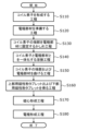
- FIG. 3 is a flowchart showing a method for manufacturing an inductor according to an embodiment of the present invention.
- FIG. 4 is a diagram illustrating a part of a method for manufacturing an inductor according to an embodiment of the present invention.
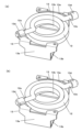
- FIG. 5 is a transparent perspective view of another inductor in an embodiment of the invention. 6 is a perspective view of a portion of another inductor shown in FIG. 5.
- FIG. FIG. 7 is a diagram illustrating a part of yet another inductor manufacturing method according to an embodiment of the present invention.
- FIG. 8 is a diagram illustrating a part of a method for manufacturing an inductor according to an embodiment of the present invention.
- FIG. 9 is a diagram illustrating a part of a method for manufacturing an inductor according to an embodiment of the present invention.
- FIG. 10 is a diagram illustrating a part of a method for manufacturing an inductor according to an embodiment of the present invention.
- FIG. 1 is a perspective view of an inductor according to an embodiment of the present invention
- FIG. 2 is a cross-sectional view of the inductor.
- the outer shape of the magnetic core is shown in broken lines in FIG.
- FIG. 2 is a cross section of the inductor taken along a plane that passes through both ends of the coil element and is perpendicular to the bottom surface of the magnetic core.
- the coil element 12 is made by winding an insulated conductor wire with a diameter of about 0.3 mm, and the end portion 12a of the coil element has the insulated coating peeled off and is crushed into a flat shape with a thickness of about 0.2 mm. .
- the magnetic core 11 is formed by embedding the coil element 12 in a magnetic material powder made by mixing a magnetic material powder made of an Fe-Si-Cr alloy and a binder made of silicone, and then press-molding the mixture.
- the magnetic core 11 has a rectangular parallelepiped shape with a planar shape of about 10 mm square and a height of about 5 mm, and has a bottom surface 11b of the magnetic core and an end surface 11a of the magnetic core connected to the bottom surface 11b of the magnetic core.
- An electrode member 13 is fixed to the end face 11a of the magnetic core and bent along the bottom face 11b of the magnetic core, and the electrode member 13 is composed of an end face portion 13a and a bottom face portion 13b.
- the electrode member 13 has a caulking portion 13d at the tip of the end face portion 13a, and is caulked by overlapping the end portion 12a of the coil element on the electrode member 13, bending the caulking portion 13d, and crimping it onto the end portion 12a of the coil element.
- the caulked portion 13d and the end portion 12a of the coil element are electrically and mechanically connected by welding.
- the caulked portion 13d is buried inside the magnetic core 11 so as to face toward the center of the magnetic core 11.
- a notch portion 12b is provided at the end portion 12a of the coil element between the winding portion of the coil element 12 and the caulking portion 13d, and the end portion 12a of the coil element is bent at the notch portion 12b. If the bent portion changes in the region embedded in the magnetic core, the shape of the coil element is likely to change, and this tends to cause variations in electrical characteristics such as inductance value. Therefore, by providing the notch portion 12b at the end portion 12a of the coil element, the shape of the coil element that is bent at the notch portion 12b can be stabilized, and the electrical characteristics can be stabilized. Usually, a notch is provided to make it easier to bend, but the provision of a notch tends to deteriorate the mechanical strength. On the other hand, in the inductor of the present embodiment, the bent portion with the notch portion 12b is embedded and fixed in the magnetic core 11, so even with the notch portion 12b provided, mechanical strength is maintained. be able to.
- the electrode member 13 is made by punching out a flat copper plate containing 99% or more of copper, and has a thickness of about 0.15 mm.
- a plating layer 13f plated with nickel and tin in this order is provided on one surface of the electrode member 13, and copper is exposed on the other surface.
- the plated layer 13f is provided on the surface of the electrode member 13 opposite to the surface facing the magnetic core 11, soldering to the mounting board is facilitated.
- the bonding strength between the magnetic core 11 and the electrode member 13 can be maintained even when the temperature is high during solder reflow or the like.
- the electrode member 13 on the end face 11a side of the magnetic core is embedded and fixed in the magnetic core 11, vibration resistance can be improved.
- the electrode member 13 on the bottom surface 11b side of the magnetic core is not fixed to the magnetic core 11, even if the thermal expansion coefficients of the mounting board and the inductor are different, the influence of elongation due to heat cycles can be alleviated, and the electrode member 13 can be heat resistant. Cyclability can be improved.
- the angle between the bottom surface 11b of the magnetic core (the extension of the bottom surface 11b of the magnetic core is shown by a broken line in FIG. 2) and the surface 11c of the end surface portion of the electrode member on the end surface 11a side of the magnetic core (shown by a dashed line in FIG. 2) is approximately The angle is 86.5°, and the angle between the bottom surface 11b of the magnetic core and the end surfaces 11a' of the magnetic core on both sides of the electrode member 13 (in FIG. 2, the extended line of the end surfaces 11a' of the magnetic core on both sides of the electrode member is shown by a chain double-dashed line) The angle is approximately 89.5°.
- the reference surface of the bottom surface 11b of the magnetic core at this time means a surface placed on a flat plate with the electrode member 13 on the bottom surface 11b side of the magnetic core removed.
- the reason why the angle between the bottom surface 11b of the magnetic core and the end surfaces 11a' of the magnetic core on both sides of the electrode member 13 is approximately 89.5°, which is smaller than 90.0°, is because the magnetic core 11 is extracted from the mold when it is pressure-molded. It is slightly sloped to make it easier.
- the inclination is an inclination with respect to a line along the pressing direction during pressure molding, or in other words, an inclination with respect to a line perpendicular to the bottom surface 11b of the magnetic core.
- the entire magnetic core tends to expand when taken out. Therefore, the electrode member disposed on the end face side of the magnetic core is also pressed against the wall of the mold with strong stress, and becomes easily damaged.
- the end surfaces 11a' of the magnetic core on both sides of the electrode member on the end surface 11a side of the magnetic core are more perpendicular to the bottom surface 11b of the magnetic core than the end surface portion 13a of the electrode member.
- the end surfaces 11a' of the magnetic core on both sides of the electrode member on the end surface 11a side of the magnetic core act as a support, and the expansion of the surface 11c of the end surface portion of the electrode member is prevented. It can be suppressed. Therefore, the end surface portion 13a of the electrode member 13 on the side of the end surface 11a of the magnetic core can be made less likely to be damaged.
- the end surface portion 13a of the electrode member 13 has a larger slope than the end surfaces 11a' of the magnetic core on both sides of the electrode member, the pressure that tends to spread toward the end surface 11a of the magnetic core during pressure molding is dispersed along the slope. Therefore, expansion of the entire magnetic core 11 can be suppressed.
- the angle formed between the surface 11c of the end face portion of the electrode member on the end face 11a side of the magnetic core and the end faces 11a' of the magnetic core on both sides of the electrode member is 2.0° or more and 5.0° or less.
- this angle is smaller than 2.0°, the effect of suppressing scratches on the electrode member 13 is reduced, and when it is larger than 5.0°, when bending the electrode member 13 from the end surface 11a of the magnetic core toward the bottom surface 11b of the magnetic core, This is not desirable because the magnetic core 11 is likely to crack.
- the end surface portion 13a of the electrode member 13 is tapered forward with respect to the mounting surface, the solder tends to wet when this inductor is mounted and soldered. Thereby, an inductor with excellent solderability can be provided. Further, since the end face portion 13a of the electrode member 13 is tapered forward with respect to the mounting surface, it becomes easy to check the soldering state from above.
- FIG. 3 is a flowchart showing a method for manufacturing an inductor according to an embodiment of the present invention.
- the inductor manufacturing method includes a step S110 of forming a coil element, a step S115 of forming a notch at the end of the coil element, a step S120 of preparing an electrode member, and a step S120 of forming a notch at the end of the coil element.
- the process includes a step S160 of obtaining a powder tablet, a magnetic core forming step S170, and an electrode forming step S180.
- steps S110, S120, and S160 are performed in random order.
- Step S115 may be performed simultaneously with step S110.
- Step S115 only needs to be executed before step S150.
- Step S160 may be performed before step S130. Each step will be explained below.
- a coil element 12 is formed by spirally winding a conductive wire whose surface is coated with insulation, and pulling out both ends in opposite directions.
- An insulated copper wire with a diameter of about 0.3 mm is used as the conductor, and the end portion 12a of the coil element is stripped of its insulating coating and crushed into a flat shape with a thickness of about 0.2 mm.
- an electrode member 13 is obtained by punching out a flat plate having a plated layer 13f plated with nickel and tin in that order on one surface of a copper plate containing 99% or more of copper.
- the electrode member 13 includes an end surface portion 13a that is disposed on the end surface 11a of the magnetic core and connected to the end 12a of the coil element, and a bottom surface portion 13b that is connected to the end surface portion 13a and disposed on the bottom surface 11b of the magnetic core.
- a supporting portion 13c that is connected to the bottom portion 13b on the opposite side of the end surface portion 13a and is supported by a mold when the magnetic core 11 described later is press-molded is integrally formed.
- the thickness of this electrode member 13 is about 0.15 mm.
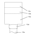
- FIG. 4 is a diagram illustrating a part of a method for manufacturing an inductor in an embodiment of the present invention.
- FIG. 4A is a plan view of the electrode member 13, in which the electrode member 13 is linearly connected to the support portion 13c, the bottom portion 13b, and the end portion 13a, and the tip of the end portion 13a is opposite to the bottom portion 13b.
- a caulking portion 13d is provided.
- the end portion 12a of the coil element is overlapped with this caulking portion 13d, and as shown in FIG. 4(b), the end portion of the coil element is 12a is crimped onto the electrode member 13 for temporary fixation.
- the tip of the end 12a of the coil element is caulked so as to overlap the electrode member 13, and the tip of the end 12a of the coil element is made to protrude from the caulking part 13d.
- the tip portion of the end portion 12a of the coil element is in a state of protruding from the caulked portion 13d.
- the length of the caulked portion 13d is approximately 1.0 mm
- the length of the tip of the end portion 12a of the coil element protruding from the caulked portion 13d is approximately 0.3 mm. Note that each length refers to the length of the end portion 12a of the coil element in the extending direction.
- the caulked portion 13d is folded back and the caulked portion is overlapped with the end portion 12a of the coil element, that is, the laser beam irradiation position 16 shown by the broken line in FIG.
- the electrode member 13 and the end portion 12a of the coil element are welded by irradiating the electrode member 13 and the end portion 12a of the coil element by scanning from the side of the coil element 12 toward the tip end while scanning in a zigzag manner, as shown in FIG. 4(c). Become.
- the tip of the end 12a of the coil element is not irradiated with laser light, but the heat generated by irradiating the laser beam is transmitted to the tip of the end 12a of the coil element, melting and solidifying the coil element.
- the tip of the end 12a has a rounded edge.
- the caulking portion 13d can be in a state before being caulked, a state after being caulked, and a state in which it is melted and solidified.
- the end portion 12a of the coil element is pulled out to the opposite end face side, and is sandwiched between the caulking portions 13d of the electrode member 13 and fixed by caulking, but it may be done as shown in FIGS. 5 and 6.
- FIG. 5 is a transparent perspective view of another inductor in an embodiment of the present invention.
- 6 is a perspective view of a portion of another inductor shown in FIG. 5.
- FIG. FIG. 6(a) shows a state in which the caulked portion 13d is caulked and fixed to the end 12a of the coil element (a state before welding), and
- FIG. 6(b) shows the end 12a of the coil element.
- a state in which the caulked portion 13d is welded is shown.
- the caulked portion 13d (a part of the electrode member 13) in the welded state shown in FIG. 6(b) is embedded in the magnetic core 11.
- the ends 12a of the coil element are pulled out in directions that correspond to diagonally opposite corners when the magnetic core 11 is viewed from above, and the caulked part 13d of the electrode member 13 is inserted into the end of the coil element. It is fixed by caulking so as to wrap it around 12a.
- the magnetic core 11 can be used effectively and the superimposition characteristics can be improved, and the winding of the coil element can be improved. Since it extends from the rotating portion toward the corner of the magnetic core 11, the connection can be made over a shorter distance, and the DC resistance can be lowered.
- the width w2 of the portion of the electrode member 13 that is bent toward the bottom surface 11b of the magnetic core is narrower than the width w1 of both ends of the electrode member 13 that protrudes from the magnetic core 11.
- FIG. 7 is a diagram illustrating a part of yet another inductor manufacturing method in an embodiment of the present invention.
- FIG. 7 shows another example of the welded state of the electrode member 13 and the end portion 12a of the coil element shown in FIG. 4(c).
- the region of the caulked portion 13d on the opposite side from the tip of the end portion 12a of the coil element also be in a melted and solidified state.
- the caulked portion 13d and the end portion 12a of the coil element caulked to the caulked portion 13d may be completely melted to form a weld ball.
- the electrode member 13 By embedding the welded portion inside the magnetic core 11, the electrode member 13 is firmly fixed to the magnetic core 11 and reliability can be improved, but it is not possible to check the welding state after the magnetic core 11 is formed. Can not. Therefore, by performing image recognition of the tip of the end 12a of the coil element after caulking and welding, and then performing image recognition again after the welding process, it is possible to confirm that the tip of the coil element has melted and solidified. It is desirable to confirm that By doing this, before burying the welded part in the magnetic core 11, it is possible to proceed to the next process after confirming that the welding has been performed reliably, and reliability can be improved. .
- to confirm that the tip of the coil element is melted and solidified means to confirm that the corner of the tip before welding has been removed and has changed to a rounded state. Examples include checking the color change of the tip before and after welding.
- the length by which the tip of the end 12a of the coil element protrudes from the caulking part 13d is desirably 0.05 mm or more and two-thirds or less of the length of the caulking part 13d. If the protruding length is shorter than 0.05 mm, it will be difficult to confirm the tip of the end portion 12a of the coil element in the crimped state by image recognition, and if the protruding length is shorter than two-thirds of the length of the crimped portion 13d, This is because if the length is too long, heat will not be sufficiently transmitted to the tip of the end portion 12a of the coil element, making it difficult to melt.
- a step of bending the end portion 12a of the coil element and the electrode member 13 is performed.
- the coil element 12 and the end face portion 13a of the electrode member 13, which are connected and integrated, are placed in the cavity of a mold for pressure-molding the magnetic core 11, which will be described later. Prepare to put it in.
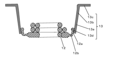
- FIG. 8 is a diagram illustrating a part of a method for manufacturing an inductor in an embodiment of the present invention.
- FIG. 8A is a cross-sectional view of the electrode member 13 welded to the end 12a of the coil element.
- a notch portion 12b is formed using a mold or the like at the end portion 12a of the coil element 12 between the wound portion and the caulked portion. Thereafter, by bending the end portion 12a of the coil element using the notch portion 12b as a starting point, it becomes as shown in FIG. 8(c).
- the shape of the coil element also tends to change, which tends to cause variations in electrical characteristics such as inductance value. Therefore, by providing the notch portion 12b at the end portion 12a of the coil element, the shape of the coil element that is bent at the notch portion 12b can be stabilized, and the electrical characteristics can be stabilized. Usually, a notch is provided to make it easier to bend, but the provision of a notch tends to deteriorate the mechanical strength.
- the bent portion with the notch portion 12b is embedded and fixed in the magnetic core 11, so even with the notch portion 12b provided, mechanical strength is maintained. be able to.
- an insulated copper wire with a diameter of about 0.3 mm is used as the conductor, and is crushed into a flat shape with a thickness of about 0.2 mm.
- a notch portion 12b having a depth of approximately 0.1 mm is provided in this flattened portion.
- the depth of the notch portion 12b is desirably 40% or more and 70% or less of the thickness of the end portion 12a of the coil element around the notch portion 12b. If the depth of the notch portion 12b is less than 40% of the thickness of the end portion 12a of the coil element around the notch portion 12b, the bending becomes difficult to stabilize. On the other hand, if the depth of the notch portion 12b is deeper than 70% of the thickness of the end portion 12a of the coil element around the notch portion 12b, the strength tends to be weakened, including during transportation.
- the notch portion may be formed before bending, and for example, the notch portion may be formed at the same time when processing the end portion of the coil element into a flat shape.
- the shape of the notch portion 12b can be triangular, semicircular, trapezoidal, etc. when viewed in cross section as shown in FIG. is more desirable. However, in the case of a triangle, it is desirable to provide an R section at its apex. In this case, it is desirable that the angle of the apex be 90° ⁇ 30°. If this angle is too small, problems such as mold life tend to occur. On the other hand, if it is too large, variations tend to occur in the starting point of bending.
- FIG. 9 is a diagram illustrating a part of a method for manufacturing an inductor in an embodiment of the present invention.
- the end portion 12a of the coil element is bent as shown in FIG. 9, and the end portion 13a and the bottom portion 13b are bent. is formed in a straight line, and the supporting portion 13c is bent outward with respect to the coil element 12.
- the end 12a of the coil element is bent after the electrode member 13 is fixed to the end 12a of the coil element, but when the configuration shown in FIGS. After the electrode member is bent, the caulking portion 13d of the electrode member may be caulked and fixed to the end portion 12a of the coil element.
- preparations for forming the magnetic core 11 are made. First, using a powder magnetic powder made by mixing magnetic material powder made of Fe-Si-Cr alloy and a binder made of silicone, first put the powder magnetic powder into a tablet molding mold and weigh approximately 0.2 tons. By compressing at a pressure of /cm 2 , a magnetic powder tablet that easily disintegrates under pressure is formed. At this time, the magnetic powder tablets are prepared separately into a lower magnetic powder tablet for forming the lower part of the magnetic core 11 and an upper magnetic powder tablet for forming the upper part of the magnetic core 11.
- the shape of the lower magnetic powder tablet it is preferable to provide a recessed portion for accommodating the coil element 12, and it is preferable that the lower magnetic powder tablet has a pot shape with an E-shaped cross section. Further, the shape of the upper magnetic powder tablet is preferably a flat plate so as to close the recessed portion of the lower magnetic powder tablet.
- FIG. 10 is a diagram illustrating a part of a method for manufacturing an inductor according to an embodiment of the present invention, in which an upper magnetic powder tablet 15a, a coil element 12, and an electrode member 13 are integrated into a cavity of a mold 14. This is a schematic representation of the state before the lower magnetic powder tablet 15b is inserted and pressure molded.
- the upper magnetic powder tablet 15a is placed in the mold 14, the integrated coil element 12 and electrode member 13 is placed on top of it, the lower magnetic powder tablet 15b is placed, and the upper punch 14a is placed in the mold 14. is lowered and the lower punch 14b is raised to perform pressure molding at a pressure of about 4 tons/cm 2 .
- the magnetic core 11 is molded within the cavity of the mold 14, and the bottom portion 13b and the supporting portion 13c of the electrode member 13 are exposed to the outside of the magnetic core 11 (cavity of the mold 14). ing.
- the position of the coil element 12 can be determined by placing the supporting portion 13c of the electrode member 13 on the mold.
- a gap may be provided above the support portion 13c.
- the lower magnetic powder tablet 15b may be placed after the coil element 12 and the electrode member 13 are put into the mold.
- a combination of the coil element 12 and the electrode member 13 combined with the lower magnetic powder tablet 15b may be placed in the mold 14.
- the end surface portion 13a of the electrode member 13 is placed inside the mold cavity.
- the magnetic core 11 is compacted and at least a portion of its thickness is embedded and fixed in the magnetic core 11.
- the bottom surface portion 13b of the electrode member 13 is not fixed to the magnetic core 11 because it is bent toward the bottom surface of the magnetic core 11 after powder molding while it is exposed outside the mold cavity.
- the surface of the electrode member 13 on the end surface 11a side of the magnetic core, on which the plating layer is not provided faces the magnetic core 11.
- the plated layer 13f is provided on the surface of the electrode member 13 opposite to the surface facing the magnetic core 11, soldering to the mounting board is facilitated.
- the bonding strength between the magnetic core 11 and the electrode member 13 can be maintained even when the temperature is high during solder reflow or the like.
- the inner wall of the mold 14 on the end surface 11a side of the magnetic core has an angle of approximately 86.5° between the surface of the upper punch 14a forming the bottom surface 11b of the magnetic core and the surface that abuts the end surface portion 13a of the electrode member 13.
- the angle between the surface of the upper punch 14a, which becomes the bottom surface 11b of the magnetic core, and both sides of the end surface portion 13a of the electrode member 13 is approximately 89.5°.
- the inner walls of the mold 14 on both sides of the end surface portion 13a of the electrode member 13 serve as supports, suppressing the expansion of the surface 11c of the end surface portion of the electrode member. It will be done. Therefore, the electrode member 13 on the end face 11a side of the magnetic core can be made less likely to be damaged.
- the shape is stabilized. Therefore, even when this inductor is mounted and soldered, stable soldering can be achieved.
- the electrode member 13 when putting the integrated coil element 12 and electrode member 13 into the mold 14, the electrode member 13 is deformed and inserted so that the distance between the end face portions 13a becomes small, and then the electrode member 13 is inserted.
- the distance between the end face portions 13a may be widened so that the end face portions 13a of the electrode member 13 come into contact with the inner wall of the mold 14, and the lower magnetic powder tablet 15b may be inserted and pressure molded.
- the magnetic core 11 is thermosetted, the supporting portion 13c of the electrode member 13 is cut, and the bottom portion 13b is bent to obtain an inductor.
- a recess is provided in the bottom surface 11b of the magnetic core.
- the electrode member 13 is bent so that the end surface portion 13a abuts the end surface 11a of the magnetic core, and a portion of the bottom surface portion 13b enters the recess.
- a gap is formed between the bottom portion 13b and the recess near the bending point of the electrode member 13.
- the tip of the bottom portion 13b is in contact with or close to the recess, and the bottom portion 13b is not embedded in the magnetic core 11.
- a magnetic core that is pressure-molded by mixing magnetic material powder and a binder and has a bottom surface and an end surface connected to the bottom surface, a coil element embedded in the magnetic core, and electrically and mechanically connected to the end of the coil element.
- the electrode member is bent from the end face of the magnetic core toward the bottom face of the magnetic core, the electrode member has a caulked portion, and the end of the coil element and the The electrode member is overlapped and caulked at the caulking portion, and the caulking portion is welded to electrically and mechanically connect the electrode member, and the caulking portion is embedded in the magnetic core, and the caulking portion At least a part of the thickness of the electrode member on the end face side is embedded and fixed in the magnetic core, and the electrode member on the bottom face side of the magnetic core is not fixed to the magnetic core.
- Example 2 A notch portion is provided at the end of the coil element between the winding portion of the coil element and the caulking portion, the end portion of the coil element is bent at the notch portion, and the caulking portion and the caulking portion are bent.
- Example 3 The angle formed between the bottom surface of the magnetic core and the end surfaces of the magnetic core on both sides of the electrode member is larger than the angle formed between the bottom surface of the magnetic core and the surface of the electrode member provided on the end surface side of the magnetic core, and The inductor according to Example 1 or Example 2, wherein the angle between the bottom surface and the end surfaces of the magnetic cores on both sides of the electrode member is smaller than 90.0°.
- Example 4 The inductor according to Example 3, wherein the angle between the surface of the electrode member provided on the end surface side of the magnetic core and the end surfaces of the magnetic core on both sides of the electrode member is 2.0° or more and 5.0° or less.
- Example 5 The inductor according to Example 1 or 2, wherein a plating layer is not provided on a surface of the electrode member that faces the magnetic core, and a plating layer is provided on a surface that does not face the magnetic core.
- Example 6 A method for manufacturing an inductor in which a coil element is embedded in a magnetic core having a bottom surface and an end surface connected to the bottom surface, and the end of the coil element is electrically and mechanically connected to an electrode member, the method comprising spirally coiling a conductive wire whose surface is insulated.
- the caulking part is embedded in the magnetic core
- the electrode member on the end surface side of the magnetic core is fixed with at least a part of its thickness embedded in the magnetic core, and The method for manufacturing an inductor in which the electrode member on the bottom surface side is not fixed to the magnetic core.
- the method further includes the step of providing a notch portion at an end of the coil element between the winding portion of the coil element and the caulking portion, and the caulking portion and the notch portion are embedded in the magnetic core.
- Example 8 The method for manufacturing an inductor according to Example 7, wherein the depth of the notch is 40% or more and 70% or less of the thickness of the end of the coil element around the notch.
- Example 7 or example 7 including a step of providing a notch portion at the end portion of the coil element in the portion to be bent, before the step of bending the end portion of the coil element or the electrode member, and the notch portion is embedded in the magnetic core. 8. The method for manufacturing an inductor according to 8.
- Example 10 By making the part of the inner wall of the mold that contacts the end face part of the electrode member different from the inclination on both sides thereof, the bottom surface of the magnetic core and the surface of the end face part of the electrode member provided on the end face side of the magnetic core are made different.
- the angle between the bottom surface of the magnetic core and the end surfaces of the magnetic core on both sides of the electrode member is made larger than the angle formed by the bottom surface of the magnetic core and the end surfaces of the magnetic core on both sides of the electrode member.
- Example 11 According to Example 6 or Example 7, the angle between the surface of the electrode member provided on the end surface side of the magnetic core and the end surfaces of the magnetic core on both sides of the electrode member is 2.0° or more and 5.0° or less. How to manufacture an inductor.
- Example 12 In the caulking process, the tip of the end of the coil element is caulked in a state protruding beyond the part to be caulked, and in the welding process, the caulked part is welded by irradiating the caulked part with a laser beam, The method for manufacturing an inductor according to Example 6 or 7, wherein the tip end of the end of the coil element after the welding step is in a melted and solidified state.
- Example 13 The method for manufacturing an inductor according to Example 6 or 7, wherein a portion of the caulked portion on the side opposite to the tip of the end of the coil element is in a melted and solidified state.
- Example 14 A state in which the tip of the end of the coil element is melted and solidified by image recognition of the tip of the end of the coil element after the caulking process and the welding process, and image recognition again after the welding process.
- Example 15 In the magnetic core forming step, when inserting the integrated coil element and the electrode member into the mold, the electrode member is deformed and inserted so that the distance between the end face portions of the electrode member becomes small; The method for manufacturing an inductor according to Example 6 or Example 7, in which the distance between the end face portions of the electrode member is then widened so that the end face portions of the electrode member contact the inner wall of the mold under pressure.
- a magnetic core is formed by pressure-molding a mixture of magnetic material powder and a binder, and has a bottom surface and an end surface connected to the bottom surface, a coil element embedded in the magnetic core, and an electrically and mechanically connected end of the coil element. and a connected electrode member, the electrode member being bent from the end face of the magnetic core toward the bottom face of the magnetic core, the electrode member having a caulked portion, and the end of the coil element and the electrode The members are overlapped and caulked at the caulking portion, and electrically and mechanically connected by welding at the caulked portion, and the caulking portion is embedded in the magnetic core and is connected to the bottom surface of the magnetic core.
- the angle between the bottom surface of the magnetic core and the end surfaces of the magnetic core on both sides of the electrode member on the end surface of the magnetic core is greater than the angle formed between the end surface of the electrode member provided on the end surface side of the magnetic core.
- the inductor is made larger and the angle between the bottom surface of the magnetic core and the end surfaces of the magnetic core on both sides of the electrode member is smaller than 90.0°.
- a magnetic core that is pressure-molded by mixing magnetic material powder and a binder and has a bottom surface and an end surface connected to the bottom surface, a coil element embedded in the magnetic core, and electrically and mechanically connected to the end of the coil element.
- an electrode member the electrode member is bent from the end face of the magnetic core toward the bottom face of the magnetic core, the electrode member has a caulked portion, and the end of the coil element and the The coil element is electrically and mechanically connected by overlapping the electrode member and caulking at the caulking part and welding at this caulking part, and between the winding part of the coil element and the caulking part.
- a notch portion is provided at the end of the coil element, the end portion of the coil element is bent at the notch portion, the caulking portion and the notch portion are embedded in the magnetic core, and the end portion of the coil element is bent at the notch portion. At least a part of the thickness of the electrode member on the end face side is embedded and fixed in the magnetic core, and the electrode member on the bottom face side of the magnetic core is not fixed to the magnetic core.
- the inductor and the manufacturing method thereof according to the present invention can provide an inductor with excellent vibration resistance and heat cycle resistance, and are industrially useful.
Landscapes
- Engineering & Computer Science (AREA)
- Power Engineering (AREA)
- Manufacturing & Machinery (AREA)
- Microelectronics & Electronic Packaging (AREA)
- Coils Or Transformers For Communication (AREA)
Priority Applications (3)
| Application Number | Priority Date | Filing Date | Title |
|---|---|---|---|
| US18/862,268 US20250299870A1 (en) | 2022-05-12 | 2023-05-10 | Inductor and method for manufacturing inductor |
| JP2024520466A JPWO2023219096A1 (https=) | 2022-05-12 | 2023-05-10 | |
| CN202380038240.8A CN119137696A (zh) | 2022-05-12 | 2023-05-10 | 电感器及电感器的制造方法 |
Applications Claiming Priority (8)
| Application Number | Priority Date | Filing Date | Title |
|---|---|---|---|
| JP2022078525 | 2022-05-12 | ||
| JP2022-078525 | 2022-05-12 | ||
| JP2022-190598 | 2022-11-29 | ||
| JP2022190600 | 2022-11-29 | ||
| JP2022190598 | 2022-11-29 | ||
| JP2022-190599 | 2022-11-29 | ||
| JP2022190599 | 2022-11-29 | ||
| JP2022-190600 | 2022-11-29 |
Publications (1)
| Publication Number | Publication Date |
|---|---|
| WO2023219096A1 true WO2023219096A1 (ja) | 2023-11-16 |
Family
ID=88730234
Family Applications (1)
| Application Number | Title | Priority Date | Filing Date |
|---|---|---|---|
| PCT/JP2023/017526 Ceased WO2023219096A1 (ja) | 2022-05-12 | 2023-05-10 | インダクタおよびインダクタの製造方法 |
Country Status (4)
| Country | Link |
|---|---|
| US (1) | US20250299870A1 (https=) |
| JP (1) | JPWO2023219096A1 (https=) |
| CN (1) | CN119137696A (https=) |
| WO (1) | WO2023219096A1 (https=) |
Cited By (1)
| Publication number | Priority date | Publication date | Assignee | Title |
|---|---|---|---|---|
| WO2025182484A1 (ja) * | 2024-02-29 | 2025-09-04 | パナソニックIpマネジメント株式会社 | インダクタおよびインダクタの製造方法 |
Families Citing this family (1)
| Publication number | Priority date | Publication date | Assignee | Title |
|---|---|---|---|---|
| CN120023642B (zh) * | 2025-04-24 | 2025-07-08 | 深圳市百斯特电子有限公司 | 一种电感用线圈焊接装置及焊接工艺 |
Citations (9)
| Publication number | Priority date | Publication date | Assignee | Title |
|---|---|---|---|---|
| JPS61186272U (https=) * | 1985-05-10 | 1986-11-20 | ||
| JP2004103862A (ja) * | 2002-09-10 | 2004-04-02 | Murata Mfg Co Ltd | 巻線型コイル部品およびコイルの導線と金属端子の接続方法 |
| JP2005026256A (ja) * | 2003-06-30 | 2005-01-27 | Tdk Corp | インダクタンス部品及びその製造方法 |
| JP2007165779A (ja) * | 2005-12-16 | 2007-06-28 | Sumida Corporation | コイル封入型磁性部品 |
| JP2014053395A (ja) * | 2012-09-06 | 2014-03-20 | Toko Inc | 面実装インダクタ |
| JP2018098312A (ja) * | 2016-12-12 | 2018-06-21 | パナソニックIpマネジメント株式会社 | インダクター |
| WO2019004038A1 (ja) * | 2017-06-29 | 2019-01-03 | パナソニックIpマネジメント株式会社 | インダクタ部品およびその製造方法 |
| JP2021005602A (ja) * | 2019-06-25 | 2021-01-14 | 新光電気工業株式会社 | インダクタ、及びインダクタの製造方法 |
| JP2022060975A (ja) * | 2020-10-05 | 2022-04-15 | 株式会社村田製作所 | インダクタ、及びインダクタの製造方法 |
-
2023
- 2023-05-10 US US18/862,268 patent/US20250299870A1/en active Pending
- 2023-05-10 JP JP2024520466A patent/JPWO2023219096A1/ja active Pending
- 2023-05-10 WO PCT/JP2023/017526 patent/WO2023219096A1/ja not_active Ceased
- 2023-05-10 CN CN202380038240.8A patent/CN119137696A/zh active Pending
Patent Citations (9)
| Publication number | Priority date | Publication date | Assignee | Title |
|---|---|---|---|---|
| JPS61186272U (https=) * | 1985-05-10 | 1986-11-20 | ||
| JP2004103862A (ja) * | 2002-09-10 | 2004-04-02 | Murata Mfg Co Ltd | 巻線型コイル部品およびコイルの導線と金属端子の接続方法 |
| JP2005026256A (ja) * | 2003-06-30 | 2005-01-27 | Tdk Corp | インダクタンス部品及びその製造方法 |
| JP2007165779A (ja) * | 2005-12-16 | 2007-06-28 | Sumida Corporation | コイル封入型磁性部品 |
| JP2014053395A (ja) * | 2012-09-06 | 2014-03-20 | Toko Inc | 面実装インダクタ |
| JP2018098312A (ja) * | 2016-12-12 | 2018-06-21 | パナソニックIpマネジメント株式会社 | インダクター |
| WO2019004038A1 (ja) * | 2017-06-29 | 2019-01-03 | パナソニックIpマネジメント株式会社 | インダクタ部品およびその製造方法 |
| JP2021005602A (ja) * | 2019-06-25 | 2021-01-14 | 新光電気工業株式会社 | インダクタ、及びインダクタの製造方法 |
| JP2022060975A (ja) * | 2020-10-05 | 2022-04-15 | 株式会社村田製作所 | インダクタ、及びインダクタの製造方法 |
Cited By (1)
| Publication number | Priority date | Publication date | Assignee | Title |
|---|---|---|---|---|
| WO2025182484A1 (ja) * | 2024-02-29 | 2025-09-04 | パナソニックIpマネジメント株式会社 | インダクタおよびインダクタの製造方法 |
Also Published As
| Publication number | Publication date |
|---|---|
| US20250299870A1 (en) | 2025-09-25 |
| JPWO2023219096A1 (https=) | 2023-11-16 |
| CN119137696A (zh) | 2024-12-13 |
Similar Documents
| Publication | Publication Date | Title |
|---|---|---|
| CN208111262U (zh) | 线圈部件 | |
| TWI608502B (zh) | 扼流線圈及其製造方法 | |
| US11935689B2 (en) | Method for manufacturing coil component having coil part with flat-shaped connection end parts | |
| JP6065122B2 (ja) | 巻線型電子部品及び巻線型電子部品の製造方法 | |
| WO2023219096A1 (ja) | インダクタおよびインダクタの製造方法 | |
| JP2009076610A (ja) | 磁性部品 | |
| KR20120085176A (ko) | 코일 부품 | |
| CN104425105A (zh) | 线圈组件 | |
| CN102290194A (zh) | 线圈元件 | |
| WO2019004038A1 (ja) | インダクタ部品およびその製造方法 | |
| US11798732B2 (en) | Coil component manufacturing method | |
| JP5877296B2 (ja) | コイル部品およびその製造方法 | |
| TW201243878A (en) | Inductance element | |
| JP2019192842A (ja) | インダクタおよびその製造方法 | |
| JP6547123B2 (ja) | コイル部品およびその製造方法 | |
| JP2011138911A (ja) | 巻線型コイル部品およびその製造方法 | |
| JP2014049528A (ja) | インダクタ及びその製造方法 | |
| JP2010109211A (ja) | 電子部品及びその製造方法 | |
| JP2019009286A (ja) | コイル部品 | |
| JP6681544B2 (ja) | 電子部品およびそれを用いた電子機器 | |
| US11532427B2 (en) | Coil component and electronic device | |
| WO2024166469A1 (ja) | インダクタおよびその製造方法 | |
| JP7151740B2 (ja) | 巻線用コアおよびコイル部品 | |
| US20240347255A1 (en) | Inductor and method for manufacturing same | |
| JP2015076498A (ja) | コイル部品およびその製造方法 |
Legal Events
| Date | Code | Title | Description |
|---|---|---|---|
| 121 | Ep: the epo has been informed by wipo that ep was designated in this application |
Ref document number: 23803571 Country of ref document: EP Kind code of ref document: A1 |
|
| WWE | Wipo information: entry into national phase |
Ref document number: 2024520466 Country of ref document: JP |
|
| WWE | Wipo information: entry into national phase |
Ref document number: 18862268 Country of ref document: US |
|
| WWE | Wipo information: entry into national phase |
Ref document number: 202380038240.8 Country of ref document: CN |
|
| NENP | Non-entry into the national phase |
Ref country code: DE |
|
| 122 | Ep: pct application non-entry in european phase |
Ref document number: 23803571 Country of ref document: EP Kind code of ref document: A1 |
|
| WWP | Wipo information: published in national office |
Ref document number: 18862268 Country of ref document: US |