WO2023219018A1 - タイヤ - Google Patents
タイヤ Download PDFInfo
- Publication number
- WO2023219018A1 WO2023219018A1 PCT/JP2023/016933 JP2023016933W WO2023219018A1 WO 2023219018 A1 WO2023219018 A1 WO 2023219018A1 JP 2023016933 W JP2023016933 W JP 2023016933W WO 2023219018 A1 WO2023219018 A1 WO 2023219018A1
- Authority
- WO
- WIPO (PCT)
- Prior art keywords
- point
- tire
- range
- cross
- respect
- Prior art date
- Legal status (The legal status is an assumption and is not a legal conclusion. Google has not performed a legal analysis and makes no representation as to the accuracy of the status listed.)
- Ceased
Links
Images



Classifications
-
- B—PERFORMING OPERATIONS; TRANSPORTING
- B60—VEHICLES IN GENERAL
- B60C—VEHICLE TYRES; TYRE INFLATION; TYRE CHANGING; CONNECTING VALVES TO INFLATABLE ELASTIC BODIES IN GENERAL; DEVICES OR ARRANGEMENTS RELATED TO TYRES
- B60C13/00—Tyre sidewalls; Protecting, decorating, marking, or the like, thereof
- B60C13/003—Tyre sidewalls; Protecting, decorating, marking, or the like, thereof characterised by sidewall curvature
-
- B—PERFORMING OPERATIONS; TRANSPORTING
- B60—VEHICLES IN GENERAL
- B60C—VEHICLE TYRES; TYRE INFLATION; TYRE CHANGING; CONNECTING VALVES TO INFLATABLE ELASTIC BODIES IN GENERAL; DEVICES OR ARRANGEMENTS RELATED TO TYRES
- B60C11/00—Tyre tread bands; Tread patterns; Anti-skid inserts
-
- B—PERFORMING OPERATIONS; TRANSPORTING
- B60—VEHICLES IN GENERAL
- B60C—VEHICLE TYRES; TYRE INFLATION; TYRE CHANGING; CONNECTING VALVES TO INFLATABLE ELASTIC BODIES IN GENERAL; DEVICES OR ARRANGEMENTS RELATED TO TYRES
- B60C11/00—Tyre tread bands; Tread patterns; Anti-skid inserts
- B60C11/01—Shape of the shoulders between tread and sidewall, e.g. rounded, stepped or cantilevered
-
- B—PERFORMING OPERATIONS; TRANSPORTING
- B60—VEHICLES IN GENERAL
- B60C—VEHICLE TYRES; TYRE INFLATION; TYRE CHANGING; CONNECTING VALVES TO INFLATABLE ELASTIC BODIES IN GENERAL; DEVICES OR ARRANGEMENTS RELATED TO TYRES
- B60C3/00—Tyres characterised by the transverse section
- B60C3/04—Tyres characterised by the transverse section characterised by the relative dimensions of the section, e.g. low profile
-
- B—PERFORMING OPERATIONS; TRANSPORTING
- B60—VEHICLES IN GENERAL
- B60C—VEHICLE TYRES; TYRE INFLATION; TYRE CHANGING; CONNECTING VALVES TO INFLATABLE ELASTIC BODIES IN GENERAL; DEVICES OR ARRANGEMENTS RELATED TO TYRES
- B60C9/00—Reinforcements or ply arrangement of pneumatic tyres
- B60C9/18—Structure or arrangement of belts or breakers, crown-reinforcing or cushioning layers
- B60C9/28—Structure or arrangement of belts or breakers, crown-reinforcing or cushioning layers characterised by the belt or breaker dimensions or curvature relative to carcass
-
- B—PERFORMING OPERATIONS; TRANSPORTING
- B60—VEHICLES IN GENERAL
- B60C—VEHICLE TYRES; TYRE INFLATION; TYRE CHANGING; CONNECTING VALVES TO INFLATABLE ELASTIC BODIES IN GENERAL; DEVICES OR ARRANGEMENTS RELATED TO TYRES
- B60C11/00—Tyre tread bands; Tread patterns; Anti-skid inserts
- B60C11/0008—Tyre tread bands; Tread patterns; Anti-skid inserts characterised by the tread rubber
- B60C2011/0016—Physical properties or dimensions
- B60C2011/0033—Thickness of the tread
-
- Y—GENERAL TAGGING OF NEW TECHNOLOGICAL DEVELOPMENTS; GENERAL TAGGING OF CROSS-SECTIONAL TECHNOLOGIES SPANNING OVER SEVERAL SECTIONS OF THE IPC; TECHNICAL SUBJECTS COVERED BY FORMER USPC CROSS-REFERENCE ART COLLECTIONS [XRACs] AND DIGESTS
- Y02—TECHNOLOGIES OR APPLICATIONS FOR MITIGATION OR ADAPTATION AGAINST CLIMATE CHANGE
- Y02T—CLIMATE CHANGE MITIGATION TECHNOLOGIES RELATED TO TRANSPORTATION
- Y02T10/00—Road transport of goods or passengers
- Y02T10/80—Technologies aiming to reduce greenhouse gasses emissions common to all road transportation technologies
- Y02T10/86—Optimisation of rolling resistance, e.g. weight reduction
Definitions
- the present invention relates to a tire, and more particularly to a tire that can achieve both low rolling resistance performance and wet performance under conditions of use at high internal pressure.
- an object of the present invention is to provide a tire that can achieve both low rolling resistance performance and wet performance under conditions of use at high internal pressure.
- a tire according to the present invention includes a carcass layer, a belt layer formed by laminating a pair of crossed belts, tread rubber and sidewall rubber, and the tire is mounted on a specified rim.
- the maximum diameter position of the tire profile is defined as point P1
- the maximum width position of the tire profile is defined as point T1
- the point T2 The intersection of a straight line passing through T1 and parallel to the tire width direction and the tire equatorial plane is defined as point T2
- a position 30% of the distance from point T1 to point T2 is defined as point T3
- the position of 20% of the distance from point T2 is defined as point T4, the position of 15% of the distance from point T1 to point T2 is defined as point T5, and the position of 10% of the distance from point T1 to point T2 is defined as point T5.
- the radial distance D3 from point P1 to point T3 is The radial distance D1 from P1 to point T1 is within the range of 0.05 ⁇ D3/D1 ⁇ 0.15, and the radial distance D6 from point P1 to point T6 is within the radial distance D3 from point P1. 3.00 ⁇ D6/D3 ⁇ 6.00, and the radius of curvature R1 of the first circular arc passing through points T3, T4, and T5 is the radius of curvature of the second circular arc passing through points T1, T6, and T7. It is characterized in that the radius R2 is in the range of 0.40 ⁇ R1/R2 ⁇ 1.00.
- the ratio D3/D1, the ratio D6/D3, and the ratio R1/R2 are optimized under conditions of use at high internal pressure, so the tire has the advantage of achieving both low rolling resistance performance and wet performance.
- the above lower limit of the ratio D3/D1 suppresses deterioration of the rolling resistance of the tire due to excessive ground contact pressure in the shoulder region of the tread portion.
- the above-mentioned upper limit of the ratio D3/D1 ensures the contact length of the tread shoulder region, thereby ensuring the wet performance of the tire.
- the above lower limit of the ratio D6/D3 suppresses a decrease in the tire contact area due to an excessive radial distance D3 from point P1 to point T3, ensuring wet performance of the tire. be done. Further, the above upper limit of the ratio D6/D3 suppresses deterioration of the rolling resistance of the tire due to an excessive rubber volume of the buttress portion. Furthermore, (3) the above lower limit of the ratio R1/R2 ensures uniformity of the ground pressure distribution on the tire contact surface, reducing energy loss during tire rolling. This reduces the rolling resistance of the tire. Further, the above upper limit of the ratio R1/R2 ensures the tension of the carcass layer 13 and the rigidity of the tire. As a result, the tire's ground contact shape is properly ensured, and the wet performance of the tire is ensured.
- FIG. 1 is a cross-sectional view in the tire meridian direction showing a tire according to an embodiment of the present invention.
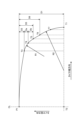
- FIG. 2 is an explanatory diagram showing the profile of the tire shown in FIG. 1.
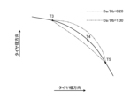
- FIG. 3 is an enlarged view showing a main part of the tire profile shown in FIG. 2.
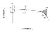
- FIG. 4 is an explanatory diagram showing a tread portion of the tire shown in FIG. 1.
- FIG. 5 is an explanatory diagram showing a modification of the tire shown in FIG. 4.
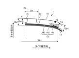
- FIG. 6 is an enlarged view showing the tread portion of the tire shown in FIG.
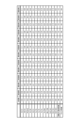
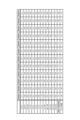
- FIG. 7 is a chart showing the results of a performance test of a tire according to an embodiment of the present invention.
- FIG. 8 is a chart showing the results of a performance test of a tire according to an embodiment of the present invention.
- FIG. 9 is a chart showing the results of a performance test of a tire according to an embodiment of the present invention.
- FIG. 1 is a cross-sectional view in the tire meridian direction showing a tire 1 according to an embodiment of the present invention. This figure shows a cross-sectional view of one side region in the tire radial direction.
- a pneumatic radial tire for a passenger car will be described as an example of a tire.
- a cross section in the tire meridian direction is defined as a cross section when the tire is cut along a plane that includes the tire rotation axis (not shown).
- the tire equatorial plane CL is defined as a plane that passes through the midpoint of the tire cross-sectional width defined by JATMA and is perpendicular to the tire rotation axis.
- the tire width direction is defined as a direction parallel to the tire rotation axis
- the tire radial direction is defined as a direction perpendicular to the tire rotation axis.
- the tire 1 has an annular structure centered around the tire rotation axis, and includes a pair of bead cores 11, 11, a pair of bead fillers 12, 12, a carcass layer 13, a belt layer 14, a tread rubber 15, and a pair of bead cores 11, 11, a pair of bead fillers 12, 12, a carcass layer 13, a belt layer 14, a tread rubber 15, sidewall rubber 16, 16, and a pair of rim cushion rubber 17, 17 (see FIG. 1).
- the pair of bead cores 11, 11 are formed by winding one or more bead wires made of steel in an annular shape and multiple times, and are embedded in the bead portions to form the cores of the left and right bead portions.
- the pair of bead fillers 12, 12 are arranged on the outer peripheries of the pair of bead cores 11, 11 in the tire radial direction, respectively, to reinforce the bead portions.
- the carcass layer 13 has a single layer structure consisting of one carcass ply or a multilayer structure consisting of a plurality of carcass plies laminated, and is spanned in a toroidal shape between the left and right bead cores 11, 11, and is the frame of the tire. Configure. Further, both ends of the carcass layer 13 are wound back and locked outward in the tire width direction so as to wrap around the bead core 11 and bead filler 12. Further, the carcass ply of the carcass layer 13 is constructed by rolling a plurality of carcass cords made of steel or organic fiber material (for example, aramid, nylon, polyester, rayon, etc.) with coated rubber, and has a thickness of 80 [deg].
- the cord angle (defined as the inclination angle of the carcass cord in the longitudinal direction with respect to the tire circumferential direction) is greater than or equal to 100 [deg] or less.
- the belt layer 14 is formed by laminating a plurality of belt plies 141 to 143, and is arranged to be wrapped around the outer periphery of the carcass layer 13.
- Belt plies 141 to 143 include a pair of crossed belts 141 and 142 and a belt cover 143.
- the pair of crossed belts 141 and 142 are constructed by rolling a plurality of belt cords made of steel or organic fibers coated with rubber, and have a cord angle of 15 [deg] or more and 55 [deg] or less in absolute value ( (defined as the inclination angle of the belt cord in the longitudinal direction with respect to the tire circumferential direction). Further, the pair of crossed belts 141 and 142 have cord angles of opposite signs and are laminated with the longitudinal directions of the belt cords crossing each other (so-called cross-ply structure). Further, the pair of crossing belts 141 and 142 are stacked and arranged on the outside of the carcass layer 13 in the tire radial direction.
- the intersecting belt 141 on the inner side in the tire radial direction is defined as an inner intersecting belt
- the intersecting belt 142 on the outer side in the tire radial direction is defined as an outer intersecting belt.
- the belt cover 143 is constructed by covering a belt cover cord made of steel or organic fiber material with a coated rubber, and has a cord angle of 0 [deg] or more and 10 [deg] or less in absolute value.
- the belt cover 143 is, for example, a strip material made by covering one or more belt cover cords with a coated rubber. It is made up of two spiral wraps. Further, a belt cover 143 is arranged to cover the entire area of the crossing belts 141 and 142.
- the tread rubber 15 is arranged on the outer periphery of the carcass layer 13 and the belt layer 14 in the tire radial direction, and constitutes the tread portion of the tire 1.
- a pair of sidewall rubbers 16, 16 are arranged on the outside of the carcass layer 13 in the tire width direction, respectively, and constitute left and right sidewall portions.
- a pair of rim cushion rubbers 17, 17 extend from the inner side in the tire radial direction to the outer side in the tire width direction of the rolled-up portion of the left and right bead cores 11, 11 and the carcass layer 13, and constitute a rim fitting surface of the bead portion.
- FIG. 2 is an explanatory diagram showing the profile of the tire 1 shown in FIG. The figure shows a profile from the tire equatorial plane CL to the tire maximum width position T1.
- the tire profile has a bilaterally symmetrical structure centered on the tire equatorial plane CL, a one-sided region with the tire equatorial plane CL as a boundary will be described in detail.
- the maximum diameter position of the tire profile is defined as point P1 in a cross-sectional view in the tire meridian direction in an unloaded state where the tire is mounted on a specified rim and 230 [kPa] is applied. Furthermore, the maximum width position of the tire profile is defined as point T1.
- the standard rim refers to the "Standard Rim” specified by JATMA, the "Design Rim” specified by TRA, or the “MEASURING RIM” specified by ETRTO.
- the specified internal pressure mentioned below refers to the "maximum air pressure” specified by JATMA, the maximum value of "TIRE LOAD LIMITS AT VARIOUS COLD INFLATION PRESSURES" specified by TRA, or "INFLATION PRESSURES" specified by ETRTO. .
- the specified load refers to the "maximum load capacity" specified in JATMA, the maximum value of "TIRE LOAD LIMITS AT VARIOUS COLD INFLATION PRESSURES" specified in TRA, or "LOAD CAPACITY" specified in ETRTO.
- JATMA for passenger car tires, the specified internal pressure is 180 [kPa], and the specified load is 88 [%] of the maximum load capacity at the specified internal pressure.
- Point P1 at the maximum diameter position of the tire profile is defined as the intersection of the tire profile and the tire equatorial plane CL in a cross-sectional view in the tire meridian direction.
- the point T1 at the maximum width position of the tire profile is defined as the end point of the tire cross-sectional width DW. Further, the radial distance D1 from point P1 to point T1 is in the range of 0.15 ⁇ D1/(OD/2) ⁇ 0.20 with respect to the tire outer diameter OD (not shown).
- Tire cross-sectional width DW is measured as the straight-line distance between the sidewalls excluding patterns, letters, etc. on the side of the tire when the tire is mounted on a specified rim and applied with 230 [kPa] and under no load. .
- point T2 intersection of a straight line passing through point T1 and parallel to the tire width direction and the tire equatorial plane CL is defined as point T2. Further, a position 30% of the distance from point T1 to point T2 is defined as point T3. Further, a position 20% of the distance from point T1 to point T2 is defined as point T4. Further, a position 15% of the distance from point T1 to point T2 is defined as point T5. Further, a position 10% of the distance from point T1 to point T2 is defined as point T6. Further, a position 3% of the distance from point T1 to point T2 is defined as point T7.
- the radial distance D3 from point P1 to point T3 is in the range of 0.05 ⁇ D3/D1 ⁇ 0.15 with respect to the radial distance D1 from point P1 to point T1, preferably 0.05 ⁇ D3/D1 ⁇ 0.15. It is in the range of 10 ⁇ D3/D1 ⁇ 0.13.
- the radial distance D6 from point P1 to point T6 is in the range of 3.00 ⁇ D6/D3 ⁇ 6.00 with respect to the radial distance D3 from point P1, preferably 3.20 ⁇ D6/D3. It is in the range of ⁇ 5.00, more preferably in the range of 3.50 ⁇ D6/D3 ⁇ 4.50.
- the radius of curvature R1 of the first circular arc passing through points T3, T4, and T5 is within the range of 0.40 ⁇ R1/R2 ⁇ 1.00 with respect to the radius of curvature R2 of the second circular arc passing through points T1, T6, and T7. It is preferably in the range of 0.45 ⁇ R1/R2 ⁇ 0.85, more preferably in the range of 0.50 ⁇ R1/R2 ⁇ 0.70. Further, the radius of curvature R1 is in the range of 20 [mm] ⁇ R1 ⁇ 50 [mm], more preferably in the range of 22 [mm] ⁇ R1 ⁇ 35 [mm].
- the ratio D3/D1, the ratio D6/D3, and the ratio R1/R2 are optimized under the usage condition of high internal pressure, so that the low rolling resistance performance and wet performance of the tire are compatible.
- the above lower limit of the ratio D3/D1 suppresses deterioration of the rolling resistance of the tire due to excessive ground contact pressure in the shoulder region of the tread portion.
- the above-mentioned upper limit of the ratio D3/D1 ensures the contact length of the tread shoulder region, thereby ensuring the wet performance of the tire.
- the above lower limit of the ratio D6/D3 suppresses a decrease in the tire contact area due to an excessive radial distance D3 from point P1 to point T3, ensuring wet performance of the tire. be done. Further, the above upper limit of the ratio D6/D3 suppresses deterioration of the rolling resistance of the tire due to an excessive rubber volume of the buttress portion. Furthermore, (3) the above lower limit of the ratio R1/R2 ensures uniformity of the ground pressure distribution on the tire contact surface, reducing energy loss during tire rolling. This reduces the rolling resistance of the tire. Further, the above upper limit of the ratio R1/R2 ensures the tension of the carcass layer 13 and the rigidity of the tire. As a result, the tire's ground contact shape is properly ensured, and the wet performance of the tire is ensured.
- the radial distance D5 from point P1 to point T5 is in the range of 0.20 ⁇ D5/D1 ⁇ 0.40 with respect to the radial distance D1 to point T1, preferably 0.20 ⁇ D5/D1 ⁇ 0.40. It is in the range of 30 ⁇ D5/D1 ⁇ 0.35.
- the above lower limit suppresses deterioration of the rolling resistance of the tire due to excessive ground contact pressure in the shoulder region of the tread portion.
- the above upper limit suppresses a decrease in the tire contact area due to an excessive radius of curvature of the profile from point T3 to point T5, and ensures wet performance of the tire.
- the tire contact edge (numerals omitted in the figure) when applying the above-mentioned 230 [kPa] and the specified internal pressure is located at a position between 25 [%] and 35 [%] of the distance from the above-mentioned point T1 to point T2. It is preferably at a position of 26 [%] to 33 [%]. Furthermore, it is preferable that the distance in the tire width direction from the tire ground contact end to point T3 (numerical symbol omitted in the figure) is within a range of ⁇ 5% with respect to the distance from point T1 to point T2 described above. Therefore, it is preferable that the tire ground contact edge is located at approximately the same position as point T3. Further, the tire ground contact end may be located on the inner side in the tire width direction than the point T3, or may be located on the outer side in the tire width direction (not shown).
- the tire 1 has the following profile at the specified internal pressure.
- the maximum diameter position of the tire profile is defined as point P1' (not shown; see FIG. 2).
- the maximum width position of the tire profile is defined as point T1'.
- the intersection of the tire equatorial plane CL and a straight line passing through point T1' and parallel to the tire width direction is defined as point T2'.
- a position 30% of the distance from point T1' to point T2' is defined as point T3'.
- a position 20% of the distance from point T1' to point T2' is defined as point T4'.
- a position 15% of the distance from point T1' to point T2' is defined as point T5'. Further, a position 10% of the distance from point T1' to point T2' is defined as point T6. Further, a position 3% of the distance from point T1' to point T2' is defined as point T7'.
- the radial distance D3' from point P1' to point T3' is 0.05 ⁇ D3'/D1' ⁇ 0.15 with respect to the radial distance D1' from point P1' to point T1'. It is preferably in the range of 0.08 ⁇ D3'/D1' ⁇ 0.13 (not shown). Also, the radial distance D6' from point P1' to point T6' is in the range of 3.20 ⁇ D6'/D3' ⁇ 5.00 with respect to the radial distance D3' from point P1' to point T3'. It is preferably in the range of 3.20 ⁇ D6'/D3' ⁇ 4.50.
- the radius of curvature R1' of the first circular arc passing through points T3', T4' and T5' is 0.20 ⁇ R1 with respect to the radius of curvature R2' of the second circular arc passing through points T1', T6' and T7'.
- FIG. 3 is an enlarged view showing the main parts of the tire profile shown in FIG. 2.
- the radial distance Da from point T3 to T4 is in the range of 0.20 ⁇ Da/Db ⁇ 1.30 with respect to the radial distance Db from point T4 to T5, preferably 0.40. It is in the range of ⁇ Da/Db ⁇ 1.10.
- the ground contact shape of the tire is properly ensured.
- the smaller the ratio Da/Db the smaller the radius of curvature R1 (see FIG. 2) of the first circular arc made up of points T3, T4, and T5, which reduces the ground contact of the tread shoulder region. Pressure increases.
- the lower limit of the ratio Da/Db prevents the ground pressure in the shoulder region of the tread portion from becoming excessive, thereby ensuring uniformity of the ground pressure distribution on the tire contact surface. This suppresses deterioration of the rolling resistance of the tire.
- the ratio Da/Db increases, the radius of curvature R1 of the first circular arc increases, and the ground contact area of the tire decreases. Therefore, the above upper limit of the ratio Da/Db ensures the ground contact area of the tire and ensures the wet performance of the tire.
- the radial distance Da is in the range of 2.0 [mm] ⁇ Da ⁇ 7.0 [mm].
- FIG. 4 is an explanatory diagram showing the tread portion of the tire 1 shown in FIG. 1.
- FIG. 5 is an explanatory diagram showing a modification of the tire 1 shown in FIG. 4.
- the tire 1 includes a plurality of circumferential main grooves 2c and 2s in the ground contact area of the tread surface.
- the circumferential main groove 2c closest to the tire equatorial plane CL is defined as the center main groove
- the outermost circumferential main groove in the tire width direction is defined as the shoulder main groove. Define as groove.
- the center main groove 2c is located on the tire equatorial plane CL.
- the present invention is not limited to this, and as shown in FIG. 5, the center main groove 2c may be arranged at a position away from the tire equatorial plane CL.
- the tire 1 includes three circumferential main grooves consisting of a single center main groove 2c and a pair of shoulder main grooves 2s, 2s.
- the present invention is not limited to this, and the tire 1 may include four or more circumferential main grooves (not shown).
- a pair of center main grooves 2c, 2c may be arranged on the left and right sides of the tire equatorial plane CL, or a middle main groove may be arranged between the center main groove 2c and the shoulder main groove 2s (not shown). ).
- an intersection point P2 is defined between a straight line passing through point P1 and parallel to the tire width direction and a straight line passing through intersection T5 and parallel to the tire radial direction.
- the groove cross-sectional area Ac of the center main groove 2c in a cross-sectional view in the tire meridian direction is the area of the area surrounded by the first circular arc passing through the points P2, T3, T5, and the above-mentioned points T3, T4, and T5. It is in the range of 0.30 ⁇ Ac/At ⁇ 1.00 with respect to At, preferably in the range of 0.40 ⁇ Ac/At ⁇ 0.70.
- the groove cross-sectional area Ac of the center main groove 2c is optimized. That is, the smaller the groove cross-sectional area Ac of the center main groove 2c, the smaller the groove area of the tire ground contact area, and the worse the wet performance of the tire.
- the larger the area At of the above region the larger the radius of curvature R1 (see Fig. 2) of the first arc consisting of points T3, T4, and T5, which makes the ground pressure distribution on the tire contact surface uneven, and the tire rolls. Resistance worsens. Therefore, the above lower limit of the ratio Ac/At ensures the wet performance of the tire and reduces the rolling resistance of the tire. Furthermore, as the groove cross-sectional area Ac of the center main groove 2c becomes larger, the ground contact area of the center region of the tread portion decreases, and the rolling resistance of the tire worsens.
- the above upper limit of the ratio Ac/At suppresses deterioration of the rolling resistance of the tire.
- the groove cross-sectional area Ac of the center main groove 2c in a cross-sectional view in the tire meridian direction is in the range of 1.05 ⁇ Ac/As ⁇ 1.80 with respect to the groove cross-sectional area As of the shoulder main groove 2s, and preferably It is in the range of 1.05 ⁇ Ac/As ⁇ 1.55.
- the groove cross-sectional area ratio Ac/As of the center main groove 2c and the shoulder main groove 2s is optimized. That is, since the center main groove 2c has a high degree of contribution to drainage performance, the wet performance of the tire improves as the groove cross-sectional area Ac of the center main groove 2c increases.
- the groove cross-sectional area Ac of the center main groove 2c becomes larger, the ground contact area of the center region of the tread portion decreases, and the rolling resistance of the tire worsens.
- the larger the groove cross-sectional area As of the shoulder main groove 2s the more uneven the ground contact pressure distribution on the tire contact surface becomes, and the worse the rolling resistance of the tire becomes. Therefore, with the above lower limit, the groove cross-sectional area Ac of the center main groove 2c that has a high contribution to drainage performance is ensured, and the wet performance of the tire is ensured. Further, the above upper limit prevents the groove cross-sectional area As of the shoulder main groove 2s from becoming excessively large, thereby suppressing deterioration of the rolling resistance of the tire.
- Groove cross-sectional areas Ac and As of the main grooves 2c and 2s are the groove wall surface of the main groove and the tire profile in a cross-sectional view in the tire meridian direction when the tire is mounted on a specified rim and under no load of 230 [kPa]. It is measured as the area of the region surrounded by and. Further, in a configuration in which the main groove has a chamfered portion at the groove opening (not shown), the areas of the chamfered portions are added to calculate the groove cross-sectional areas Ac and As. On the other hand, in a configuration in which the main groove has decorative unevenness on the groove wall (not shown), the groove cross-sectional areas Ac and As are calculated using the groove wall surface excluding these unevenness. Further, in a configuration in which the groove area of the main groove changes in the tire circumferential direction (not shown), the maximum value of the groove cross-sectional area over the entire circumference of the tire is used as the groove cross-sectional area Ac, As.
- FIG. 6 is an enlarged view showing the tread portion of the tire 1 shown in FIG. 1.
- the figure shows a tread portion in one side region whose boundary is the tire equatorial plane CL.
- the distance Ds from the tire equatorial plane CL to the shoulder main groove 2s is in the range of 0.03 ⁇ Ds/DW ⁇ 0.20 with respect to the tire cross-sectional width DW, preferably 0.10 ⁇ Ds/ DW is in the range of 0.20.
- the position of the shoulder main groove 2s is optimized.
- the above lower limit ensures the rigidity of the tread center region and reduces the rolling resistance of the tire.
- the above upper limit ensures the drainage effect of the shoulder main groove 2s and ensures the wet performance of the tire.
- the distance Ds to the shoulder main groove 2s is measured using the groove center line of the shoulder main groove 2s as the end point when the tire is mounted on a specified rim and 230 [kPa] is applied and no load is applied.
- the groove center line of the shoulder main groove 2s is defined as a virtual line connecting the midpoints of the end points of the groove width.
- the virtual line of the groove centerline is defined as a straight line passing through the amplitude centerline and parallel to the tire equatorial plane.
- the tire cross-sectional width DW is in the range of DW/OD ⁇ 0.40 with respect to the tire outer diameter OD (not shown), and preferably in the range of DW/OD ⁇ 0.35.
- the belt width Wb1 of the wide cross belt (inner diameter side cross belt 141 in FIG. 1) of the pair of cross belts 141 and 142 is 0.60 ⁇ Wb1/with respect to the tire cross-sectional width DW. DW ⁇ 0.90, preferably 0.70 ⁇ Wb1/DW ⁇ 0.85. Thereby, the belt width Wb1 is optimized.
- the width Wb1 of the belt ply is the distance in the tire width direction between the left and right ends of the belt ply (more specifically, the outermost belt cord in the tire width direction), and is 230 [ kPa] and measured in a no-load state.
- the inner diameter cross belt 141 and the outer diameter cross belt 142 of the belt layer 14 have a laterally symmetrical structure with the tire equatorial plane CL as the center.
- the inner diameter cross belt 141 is wider than the outer diameter cross belt 142.
- the edge portion of the inner diameter cross belt 141 is located between the point T3 and the point T4 in the tire width direction.
- the gauge Ga3 from point T3 to the outer diameter side cross belt 142 is in the range of 0.70 ⁇ Ga3/Ga1 ⁇ 0.98 with respect to the gauge Ga1 from the point P1 to the outer diameter side cross belt 142. It is preferably in the range of 0.80 ⁇ Ga3/Ga1 ⁇ 0.98.
- Gauges Ga1 and Ga3 up to the outer diameter side cross belt 142 are measured as the length of a perpendicular line drawn from each point P1 and T3 on the tire profile to the outer surface of the outer diameter side cross belt 142.
- the outer surface of the outer diameter cross belt 142 is defined as an imaginary line (not shown) connecting the outer ends of the belt cords that constitute the outer diameter cross belt 142.
- the gauge Gb3 from point T3 to the inner surface of the tire is in the range of 0.80 ⁇ Gb3/Gb1 ⁇ 1.10 with respect to the gauge Gb1 from point P1 to the inner surface of the tire, preferably 0.90. It is in the range of ⁇ Gb3/Gb1 ⁇ 1.10.
- the gauge Gb4 from point T4 to the inner surface of the tire is in the range of 0.70 ⁇ Gb4/Gb3 ⁇ 1.10 with respect to the gauge Gb3 from point T3 to the inner surface of the tire, preferably 0.75 It is in the range of ⁇ Gb4/Gb3 ⁇ 1.05.
- Gauges Gb1, Gb3, and Gb4 to the inner surface of the tire are measured as the length of a perpendicular line drawn from each point P1, T3 on the tire profile to the inner surface of the tire.
- This tire 1 includes a carcass layer 13, a belt layer 14 formed by laminating a pair of crossed belts 141 and 142, a tread rubber 15, and a sidewall rubber 16 (see FIG. reference).
- the maximum diameter position of the tire profile is defined as point P1
- the maximum width position of the tire profile is defined as point T1
- the intersection of a straight line passing through point T1 and parallel to the tire width direction and the tire equatorial plane is defined as point T2
- a position 30% of the distance from point T1 to point T2 is defined as point T3.
- the position of 20% of the distance from point T1 to point T2 is defined as point T4
- the position of 15% of the distance from point T1 to point T2 is defined as point T5
- point T1 The position of 10% of the distance from point T2 to point T2 is defined as point T6, and the position of 3% of the distance from point T1 to point T2 is defined as point T7 (see FIG. 2).
- the radial distance D3 from point P1 to point T3 is in the range of 0.05 ⁇ D3/D1 ⁇ 0.15 with respect to the radial distance D1 from point P1 to point T1.
- the radial distance D6 from point P1 to point T6 is in the range of 3.00 ⁇ D6/D3 ⁇ 6.00 with respect to the radial distance D3 from point P1.
- the radius of curvature R1 of the first circular arc passing through points T3, T4, and T5 is within the range of 0.40 ⁇ R1/R2 ⁇ 1.00 with respect to the radius of curvature R2 of the second circular arc passing through points T1, T6, and T7. It is in.
- the ratio D3/D1, the ratio D6/D3, and the ratio R1/R2 are optimized under conditions of use at high internal pressure, so there is an advantage that low rolling resistance performance and wet performance of the tire are compatible.
- the above lower limit of the ratio D3/D1 suppresses deterioration of the rolling resistance of the tire due to excessive ground contact pressure in the shoulder region of the tread portion.
- the above-mentioned upper limit of the ratio D3/D1 ensures the contact length of the tread shoulder region, thereby ensuring the wet performance of the tire.
- the above lower limit of the ratio D6/D3 suppresses a decrease in the tire contact area due to an excessive radial distance D3 from point P1 to point T3, ensuring wet performance of the tire. . Further, the above upper limit of the ratio D6/D3 suppresses deterioration of the rolling resistance of the tire due to an excessive rubber volume of the buttress portion. Furthermore, (3) the above lower limit of the ratio R1/R2 ensures uniformity of the ground pressure distribution on the tire contact surface, reducing energy loss during tire rolling. This reduces the rolling resistance of the tire. Further, the above upper limit of the ratio R1/R2 ensures the tension of the carcass layer 13 and the rigidity of the tire. As a result, the tire's ground contact shape is properly ensured, and the wet performance of the tire is ensured.
- the radial distance D5 from point P1 to point T5 is 0.20 ⁇ D5/D1 with respect to the radial distance D1 from point P1 to point T1. It is in the range of ⁇ 0.40 (see Figure 2). Thereby, there is an advantage that the ground contact shape of the tire is properly ensured.
- the radius of curvature R1 of the first circular arc is in the range of 20 [mm] ⁇ R1 ⁇ 50 [mm]. (See Figure 2). Thereby, there is an advantage that the ground contact shape of the tire is properly ensured.
- this tire 1 includes a plurality of circumferential main grooves 2c and 2s (see FIG. 1). Also, when defining an intersection point P2 between a straight line passing through point P1 and parallel to the tire width direction and a straight line passing through point T5 and parallel to the tire radial direction, the groove cross-sectional area of the center main groove 2c in a cross-sectional view in the tire meridian direction is Ac is in the range of 0.30 ⁇ Ac/At ⁇ 1.00 with respect to the area At of the area surrounded by the intersection P2, the point T3, the point T5, and the first circular arc. This has the advantage of optimizing the groove cross-sectional area Ac of the center main groove 2c.
- the groove cross-sectional area Ac of the center main groove 2c in a cross-sectional view in the tire meridian direction is 1.05 ⁇ with respect to the groove cross-sectional area As of the shoulder main groove 2s. It is in the range of Ac/As ⁇ 1.80 (see FIG. 4). This has the advantage of optimizing the groove cross-sectional area ratio Ac/As of the center main groove 2c and the shoulder main groove 2s.
- the distance Ds from the tire equatorial plane CL to the shoulder main groove 2s is different from the tire cross-sectional width DW ( (see FIG. 1) is in the range of 0.03 ⁇ Ds/DW ⁇ 0.20.
- the above lower limit ensures the rigidity of the tread center region and reduces the rolling resistance of the tire.
- the above upper limit ensures the drainage effect of the shoulder main groove 2s and ensures the wet performance of the tire.
- the tire cross-sectional width DW (see Fig. 1) is DW/OD ⁇ 0.40 with respect to the tire outer diameter OD. within the range of This has the advantage of optimizing the tire cross-sectional width DW.
- the wide cross belt (inner diameter side cross belt 141 in FIG. 1) of the pair of cross belts 141 and 142 is
- the belt width Wb1 is in the range of 0.60 ⁇ Wb1/DW ⁇ 0.90 with respect to the tire cross-sectional width DW. This has the advantage of optimizing the belt width Wb1.
- the gauge Ga3 from the point T3 to the outer diameter side intersecting belt 142 of the pair of intersecting belts 141, 142 is The gauge Ga1 from the point P1 to the outer diameter cross belt 142 is in the range of 0.70 ⁇ Ga3/Ga1 ⁇ 0.98 (see FIG. 6). This has the advantage of optimizing the tread gauge in the shoulder region of the tread portion.
- the gauge Gb3 from point T3 to the inner surface of the tire is 0.0 compared to the gauge Gb1 from point P1 to the inner surface of the tire. It is in the range of 80 ⁇ Gb3/Gb1 ⁇ 1.10 (see FIG. 6). This has the advantage of optimizing the total gauge of the tread shoulder region.
- the gauge Gb4 from point T4 to the inner surface of the tire is 0. It is in the range of 70 ⁇ Gb4/Gb3 ⁇ 1.10 (see FIG. 6). This has the advantage of optimizing the ground contact shape of the tread shoulder region.
- test tires of Examples and Comparative Examples have the configurations shown in FIGS. 1 and 2. Further, the tire outer diameter OD (not shown) is 640 [mm], and the tire cross-sectional width DW (see FIG. 1) is 211 [mm]. Further, the radial distance D1 from point P1 to point T1 is 63 [mm].
- test tire of the example can achieve both low rolling resistance performance and wet performance of the tire under usage conditions at high internal pressure.
Landscapes
- Engineering & Computer Science (AREA)
- Mechanical Engineering (AREA)
- Tires In General (AREA)
Abstract
Description
図1は、この発明の実施の形態にかかるタイヤ1を示すタイヤ子午線方向の断面図である。同図は、タイヤ径方向の片側領域の断面図を示している。この実施の形態では、タイヤの一例として、乗用車用空気入りラジアルタイヤについて説明する。
図2は、図1に記載したタイヤ1のプロファイルを示す説明図である。同図は、タイヤ赤道面CLからタイヤ最大幅位置T1までのプロファイルを示している。ここでは、タイヤプロファイルがタイヤ赤道面CLを中心とする左右対称な構造を有するため、タイヤ赤道面CLを境界とする片側領域について詳細に説明する。
以上説明したように、[1]このタイヤ1は、カーカス層13と、一対の交差ベルト141、142を積層して成るベルト層14と、トレッドゴム15およびサイドウォールゴム16とを備える(図1参照)。また、タイヤ1を規定リムに装着して230[kPa]を付与した無負荷状態におけるタイヤ子午線方向の断面視にて、タイヤプロファイルの最大径位置を点P1として定義し、タイヤプロファイルの最大幅位置を点T1として定義し、点T1を通りタイヤ幅方向に平行な直線とタイヤ赤道面との交点を点T2として定義し、点T1から点T2までの距離の30[%]の位置を点T3として定義し、点T1から点T2までの距離の20[%]の位置を点T4として定義し、点T1から点T2までの距離の15[%]の位置を点T5として定義し、点T1から点T2までの距離の10[%]の位置を点T6として定義し、点T1から点T2までの距離の3[%]の位置を点T7として定義する(図2参照)。このとき、点P1から点T3までの径方向距離D3が、点P1から点T1までの径方向距離D1に対して0.05≦D3/D1≦0.15の範囲にある。また、点P1から点T6までの径方向距離D6が、点P1から径方向距離D3に対して3.00≦D6/D3≦6.00の範囲にある。また、点T3、T4およびT5を通る第一円弧の曲率半径R1が、点T1、T6およびT7を通る第二円弧の曲率半径R2に対して0.40≦R1/R2≦1.00の範囲にある。
Claims (12)
- カーカス層と、一対の交差ベルトを積層して成るベルト層と、トレッドゴムおよびサイドウォールゴムとを備えるタイヤであって、
タイヤを規定リムに装着して230[kPa]を付与した無負荷状態におけるタイヤ子午線方向の断面視にて、タイヤプロファイルの最大径位置を点P1として定義し、タイヤプロファイルの最大幅位置を点T1として定義し、点T1を通りタイヤ幅方向に平行な直線とタイヤ赤道面との交点を点T2として定義し、点T1から点T2までの距離の30[%]の位置を点T3として定義し、点T1から点T2までの距離の20[%]の位置を点T4として定義し、点T1から点T2までの距離の15[%]の位置を点T5として定義し、点T1から点T2までの距離の10[%]の位置を点T6として定義し、点T1から点T2までの距離の3[%]の位置を点T7として定義するときに、
点P1から点T3までの径方向距離D3が、点P1から点T1までの径方向距離D1に対して0.05≦D3/D1≦0.15の範囲にあり、
点P1から点T6までの径方向距離D6が、点P1から径方向距離D3に対して3.00≦D6/D3≦6.00の範囲にあり、且つ、
点T3、T4およびT5を通る第一円弧の曲率半径R1が、点T1、T6およびT7を通る第二円弧の曲率半径R2に対して0.40≦R1/R2≦1.00の範囲にあることを特徴とするタイヤ。 - 点P1から点T5までの径方向距離D5が、点P1から点T1までの径方向距離D1に対して0.20≦D5/D1≦0.40の範囲にある請求項1に記載のタイヤ。
- 点T3からT4までの径方向距離Daが、点T4からT5までの径方向距離Dbに対して0.20≦Da/Db≦1.30の範囲にある請求項1または2に記載のタイヤ。
- 前記第一円弧の曲率半径R1が、20[mm]≦R1≦50[mm]の範囲にある請求項1~3のいずれか一つに記載のタイヤ。
- 複数の周方向主溝を備え、
前記複数の周方向主溝のうちのタイヤ赤道面に最も近い周方向主溝をセンター主溝として定義し、
点P1を通りタイヤ幅方向に平行な直線と点T5を通りタイヤ径方向に平行な直線との交点P2を定義し、且つ、
タイヤ子午線方向の断面視における前記センター主溝の溝断面積Acが、交点P2、点T3、点T5および前記第一円弧で囲まれた領域の面積Atに対して0.30≦Ac/At≦1.00の範囲にある請求項1~4のいずれか一つに記載のタイヤ。 - 複数の周方向主溝を備え、
前記複数の周方向主溝のうちのタイヤ幅方向の最外側にある周方向主溝をショルダー主溝として定義し、且つ、
タイヤ子午線方向の断面視における前記センター主溝の溝断面積Acが、前記ショルダー主溝の溝断面積Asに対して1.05≦Ac/As≦1.80の範囲にある請求項1~5のいずれか一つに記載のタイヤ。 - 複数の周方向主溝を備え、前記複数の周方向主溝のうちのタイヤ幅方向の最外側にある周方向主溝をショルダー主溝として定義し、且つ、タイヤ赤道面から前記ショルダー主溝までの距離Dsが、タイヤ断面幅DWに対して0.03≦Ds/DW≦0.20の範囲にある請求項1~6のいずれか一つに記載のタイヤ。
- タイヤ断面幅DWが、タイヤ外径ODに対してDW/OD≦0.40の範囲にある請求項1~7のいずれか一つに記載のタイヤ。
- 前記一対の交差ベルトのうちの幅広な交差ベルトのベルト幅Wb1が、タイヤ断面幅DWに対して0.60≦Wb1/DW≦0.90の範囲にある請求項1~8のいずれか一つに記載のタイヤ。
- 点T3から前記一対の交差ベルトのうちの外径側交差ベルトまでのゲージGa3が、点P1から前記外径側交差ベルトまでのゲージGa1に対して0.70≦Ga3/Ga1≦0.98の範囲にある請求項1~9のいずれか一つに記載のタイヤ。
- 点T3からタイヤ内面までのゲージGb3が、点P1からタイヤ内面までのゲージGb1に対して0.80≦Gb3/Gb1≦1.10の範囲にある請求項1~10のいずれか一つに記載のタイヤ。
- 点T4からタイヤ内面までのゲージGb4が、点T3からタイヤ内面までのゲージGb3に対して0.70≦Gb4/Gb3≦1.10の範囲にある請求項1~11のいずれか一つに記載のタイヤ。
Priority Applications (3)
| Application Number | Priority Date | Filing Date | Title |
|---|---|---|---|
| CN202380037452.4A CN119136994A (zh) | 2022-05-11 | 2023-04-28 | 轮胎 |
| US18/863,527 US20250303801A1 (en) | 2022-05-11 | 2023-04-28 | Tire |
| DE112023001238.5T DE112023001238T5 (de) | 2022-05-11 | 2023-04-28 | Reifen |
Applications Claiming Priority (2)
| Application Number | Priority Date | Filing Date | Title |
|---|---|---|---|
| JP2022078167A JP7758952B2 (ja) | 2022-05-11 | 2022-05-11 | タイヤ |
| JP2022-078167 | 2022-05-11 |
Publications (1)
| Publication Number | Publication Date |
|---|---|
| WO2023219018A1 true WO2023219018A1 (ja) | 2023-11-16 |
Family
ID=88730469
Family Applications (1)
| Application Number | Title | Priority Date | Filing Date |
|---|---|---|---|
| PCT/JP2023/016933 Ceased WO2023219018A1 (ja) | 2022-05-11 | 2023-04-28 | タイヤ |
Country Status (5)
| Country | Link |
|---|---|
| US (1) | US20250303801A1 (ja) |
| JP (1) | JP7758952B2 (ja) |
| CN (1) | CN119136994A (ja) |
| DE (1) | DE112023001238T5 (ja) |
| WO (1) | WO2023219018A1 (ja) |
Citations (3)
| Publication number | Priority date | Publication date | Assignee | Title |
|---|---|---|---|---|
| JPH08337101A (ja) * | 1995-06-13 | 1996-12-24 | Sumitomo Rubber Ind Ltd | 空気入りタイヤ |
| JPH09254607A (ja) * | 1996-03-23 | 1997-09-30 | Bridgestone Corp | 空気入りラジアルタイヤ |
| JPH111103A (ja) * | 1997-06-12 | 1999-01-06 | Sumitomo Rubber Ind Ltd | 空気入りタイヤ |
Family Cites Families (3)
| Publication number | Priority date | Publication date | Assignee | Title |
|---|---|---|---|---|
| JP6165615B2 (ja) | 2013-12-12 | 2017-07-19 | 住友ゴム工業株式会社 | 空気入りタイヤ |
| JP7522338B2 (ja) | 2020-06-02 | 2024-07-25 | 横浜ゴム株式会社 | タイヤおよびタイヤ状態監視システム |
| JP2022012888A (ja) | 2020-07-02 | 2022-01-17 | 横浜ゴム株式会社 | タイヤ |
-
2022
- 2022-05-11 JP JP2022078167A patent/JP7758952B2/ja active Active
-
2023
- 2023-04-28 WO PCT/JP2023/016933 patent/WO2023219018A1/ja not_active Ceased
- 2023-04-28 CN CN202380037452.4A patent/CN119136994A/zh active Pending
- 2023-04-28 US US18/863,527 patent/US20250303801A1/en active Pending
- 2023-04-28 DE DE112023001238.5T patent/DE112023001238T5/de active Pending
Patent Citations (3)
| Publication number | Priority date | Publication date | Assignee | Title |
|---|---|---|---|---|
| JPH08337101A (ja) * | 1995-06-13 | 1996-12-24 | Sumitomo Rubber Ind Ltd | 空気入りタイヤ |
| JPH09254607A (ja) * | 1996-03-23 | 1997-09-30 | Bridgestone Corp | 空気入りラジアルタイヤ |
| JPH111103A (ja) * | 1997-06-12 | 1999-01-06 | Sumitomo Rubber Ind Ltd | 空気入りタイヤ |
Also Published As
| Publication number | Publication date |
|---|---|
| US20250303801A1 (en) | 2025-10-02 |
| JP7758952B2 (ja) | 2025-10-23 |
| JP2023167188A (ja) | 2023-11-24 |
| CN119136994A (zh) | 2024-12-13 |
| DE112023001238T5 (de) | 2025-01-16 |
Similar Documents
| Publication | Publication Date | Title |
|---|---|---|
| CN103813911B (zh) | 充气轮胎 | |
| CN103813912B (zh) | 充气轮胎 | |
| US9045004B2 (en) | Pneumatic tire | |
| US20200047562A1 (en) | Pneumatic Tire | |
| US20150165822A1 (en) | Pneumatic Tire | |
| US20170028788A1 (en) | Pneumatic tire | |
| JP7077556B2 (ja) | 乗用車用空気入りタイヤ | |
| JP2020121606A (ja) | 空気入りタイヤ | |
| CN107848346A (zh) | 充气轮胎 | |
| WO2016117274A1 (ja) | 空気入りタイヤ | |
| JP2019137334A (ja) | 空気入りタイヤ | |
| JP7124494B2 (ja) | 空気入りタイヤおよび空気入りタイヤの製造方法 | |
| CN109476183B (zh) | 充气轮胎 | |
| JP6010932B2 (ja) | 空気入りタイヤ | |
| US20240059101A1 (en) | Tire | |
| JP2017013564A (ja) | 空気入りタイヤおよびその製造方法 | |
| US20240140141A1 (en) | Tire | |
| JP7758952B2 (ja) | タイヤ | |
| JP7755134B2 (ja) | タイヤ | |
| JP7659156B2 (ja) | タイヤ | |
| JP7275630B2 (ja) | 空気入りタイヤ | |
| JP2023044037A (ja) | タイヤ | |
| JP2024076971A (ja) | タイヤ | |
| US20240181812A1 (en) | Tire | |
| JP7758921B2 (ja) | タイヤ |
Legal Events
| Date | Code | Title | Description |
|---|---|---|---|
| 121 | Ep: the epo has been informed by wipo that ep was designated in this application |
Ref document number: 23803496 Country of ref document: EP Kind code of ref document: A1 |
|
| WWE | Wipo information: entry into national phase |
Ref document number: 202380037452.4 Country of ref document: CN |
|
| WWE | Wipo information: entry into national phase |
Ref document number: 112023001238 Country of ref document: DE |
|
| WWE | Wipo information: entry into national phase |
Ref document number: 18863527 Country of ref document: US |
|
| 122 | Ep: pct application non-entry in european phase |
Ref document number: 23803496 Country of ref document: EP Kind code of ref document: A1 |
|
| WWP | Wipo information: published in national office |
Ref document number: 18863527 Country of ref document: US |