WO2023218897A1 - 内視鏡用プロセッサおよび内視鏡用プロセッサの制御方法 - Google Patents
内視鏡用プロセッサおよび内視鏡用プロセッサの制御方法 Download PDFInfo
- Publication number
- WO2023218897A1 WO2023218897A1 PCT/JP2023/015794 JP2023015794W WO2023218897A1 WO 2023218897 A1 WO2023218897 A1 WO 2023218897A1 JP 2023015794 W JP2023015794 W JP 2023015794W WO 2023218897 A1 WO2023218897 A1 WO 2023218897A1
- Authority
- WO
- WIPO (PCT)
- Prior art keywords
- index
- contact
- endoscope
- signal
- control unit
- Prior art date
- Legal status (The legal status is an assumption and is not a legal conclusion. Google has not performed a legal analysis and makes no representation as to the accuracy of the status listed.)
- Ceased
Links
Images





Classifications
-
- A—HUMAN NECESSITIES
- A61—MEDICAL OR VETERINARY SCIENCE; HYGIENE
- A61B—DIAGNOSIS; SURGERY; IDENTIFICATION
- A61B1/00—Instruments for performing medical examinations of the interior of cavities or tubes of the body by visual or photographical inspection, e.g. endoscopes; Illuminating arrangements therefor
- A61B1/00002—Operational features of endoscopes
- A61B1/00004—Operational features of endoscopes characterised by electronic signal processing
- A61B1/00006—Operational features of endoscopes characterised by electronic signal processing of control signals
-
- A—HUMAN NECESSITIES
- A61—MEDICAL OR VETERINARY SCIENCE; HYGIENE
- A61B—DIAGNOSIS; SURGERY; IDENTIFICATION
- A61B1/00—Instruments for performing medical examinations of the interior of cavities or tubes of the body by visual or photographical inspection, e.g. endoscopes; Illuminating arrangements therefor
-
- A—HUMAN NECESSITIES
- A61—MEDICAL OR VETERINARY SCIENCE; HYGIENE
- A61B—DIAGNOSIS; SURGERY; IDENTIFICATION
- A61B1/00—Instruments for performing medical examinations of the interior of cavities or tubes of the body by visual or photographical inspection, e.g. endoscopes; Illuminating arrangements therefor
- A61B1/04—Instruments for performing medical examinations of the interior of cavities or tubes of the body by visual or photographical inspection, e.g. endoscopes; Illuminating arrangements therefor combined with photographic or television appliances
- A61B1/045—Control thereof
-
- A—HUMAN NECESSITIES
- A61—MEDICAL OR VETERINARY SCIENCE; HYGIENE
- A61B—DIAGNOSIS; SURGERY; IDENTIFICATION
- A61B1/00—Instruments for performing medical examinations of the interior of cavities or tubes of the body by visual or photographical inspection, e.g. endoscopes; Illuminating arrangements therefor
- A61B1/06—Instruments for performing medical examinations of the interior of cavities or tubes of the body by visual or photographical inspection, e.g. endoscopes; Illuminating arrangements therefor with illuminating arrangements
-
- A—HUMAN NECESSITIES
- A61—MEDICAL OR VETERINARY SCIENCE; HYGIENE
- A61B—DIAGNOSIS; SURGERY; IDENTIFICATION
- A61B1/00—Instruments for performing medical examinations of the interior of cavities or tubes of the body by visual or photographical inspection, e.g. endoscopes; Illuminating arrangements therefor
- A61B1/06—Instruments for performing medical examinations of the interior of cavities or tubes of the body by visual or photographical inspection, e.g. endoscopes; Illuminating arrangements therefor with illuminating arrangements
- A61B1/0638—Instruments for performing medical examinations of the interior of cavities or tubes of the body by visual or photographical inspection, e.g. endoscopes; Illuminating arrangements therefor with illuminating arrangements providing two or more wavelengths
-
- A—HUMAN NECESSITIES
- A61—MEDICAL OR VETERINARY SCIENCE; HYGIENE
- A61B—DIAGNOSIS; SURGERY; IDENTIFICATION
- A61B1/00—Instruments for performing medical examinations of the interior of cavities or tubes of the body by visual or photographical inspection, e.g. endoscopes; Illuminating arrangements therefor
- A61B1/06—Instruments for performing medical examinations of the interior of cavities or tubes of the body by visual or photographical inspection, e.g. endoscopes; Illuminating arrangements therefor with illuminating arrangements
- A61B1/0655—Control therefor
Definitions
- the automatic light control function maintains the endoscopic image at a brightness suitable for diagnosis even when the doctor operates the endoscope to change the field of view.
- the endoscope 40 includes an insertion section 44, an operation section 43, a universal cord 49, and a scope connector 48.
- the insertion section 44 is elongated, and one end is connected to the operating section 43 via a folding section.
- the insertion portion 44 includes a flexible portion 441, a curved portion 442, and a tip portion 443 in this order from the operating portion 43 side.
- the bending portion 442 bends in accordance with the operation of a bending knob provided on the operation portion 43.
- the display device 16 is, for example, a liquid crystal display device or an organic EL (Electro Luminescence) display device.
- the input device 17 is, for example, a keyboard, a touch panel, a foot switch, or the like.
- the main storage device 22 is a storage device such as SRAM (Static Random Access Memory), DRAM (Dynamic Random Access Memory), or flash memory.
- SRAM Static Random Access Memory
- DRAM Dynamic Random Access Memory
- flash memory temporary stores information necessary during processing performed by the control unit 21 and programs being executed by the control unit 21 .
- the auxiliary storage device 23 is a storage device such as SRAM, flash memory, or hard disk.
- the auxiliary storage device 23 stores programs to be executed by the control unit 21 and various data necessary for executing the programs.
- the communication unit 24 is an interface that performs data communication between the endoscope processor 20 and the network.
- the display device I/F 26 is an interface that connects the endoscope processor 20 and the display device 16.
- the input device I/F 27 is an interface that connects the endoscope processor 20 and the input device 17.
- the light source 28 is, for example, a high-intensity light source such as an LED (Light Emitting Diode).
- the light source 28 may be a combination of a light source that emits broadband light, such as a xenon lamp, and an optical filter.
- the light source 28 may be an illumination LED built into the tip portion 443.
- the light source 28 is connected to the bus via a driver (not shown). Turning on, turning off, changing the brightness, and changing the color of the light source 28 are controlled by the control unit 21. Illumination light emitted from the light source 28 is supplied to the endoscope 40 via the endoscope connector 29 and the scope connector 48. The illumination light is guided by an illumination optical fiber inside the endoscope 40 to an illumination window 52 (see FIG. 2) provided at the distal end portion 443.
- FIG. 2 is an external view of the end surface of the tip portion 443.
- an observation window 51 At the tip of the tip portion 443, an observation window 51, two illumination windows 52, an air nozzle 53, a water nozzle 54, a channel outlet 55, etc. are arranged.
- FIG. 2 is an example of the appearance of the end surface of the tip portion 443, and the arrangement of each member is not limited to that shown in FIG. 2.
- the arrangement of the air supply nozzle 53 and the water supply nozzle 54 may be reversed.
- the number of lighting windows 52 may be one or three or more.
- the endoscope 40 may be of a side-viewing type in which the viewing direction is directed to the side of the insertion section 44, or a perspective-viewing type.
- FIG. 3 is an explanatory diagram illustrating the configuration and functions of the light control section 30.
- the light control section 30 includes a light control output section 31 and a photometry section 32.
- the photometry section 32 includes a brightness index acquisition section 33 and a generation section 34.
- the observation field is illuminated by the illumination light emitted from the illumination window 52.
- reflected light reflected from living tissue within the observation field forms an image on the image sensor 46 via the observation window 51 and an observation optical system (not shown).
- An imaging signal generated by the imaging device 46 is transmitted to the endoscope processor 20 via the scope connector 48.
- the endoscope connector 29 to which the scope connector 48 is connected functions as an image signal acquisition unit that acquires an image signal from the image sensor 46.
- the endoscope system 10 uses a so-called primary color image sensor 46 that outputs three color signals of R (Red), G (Green), and B (Blue). This will be explained using an example. Blue is an example of the first color. Green is an example of a second color that has a longer wavelength than the first color. Note that a complementary color imaging device 46 may be used instead of the primary color imaging device.
- the control unit 21 performs image processing based on the imaging signal and outputs an endoscopic image 61 (see FIG. 8A) of image quality suitable for endoscopy to the display device 16.
- the brightness index acquisition unit 33 acquires a brightness index based on the imaging signal.
- the brightness index is an index related to the brightness of the image photographed by the image sensor 46.
- an index related to the brightness of the B component of an image is often used. Details of the brightness index will be described later.
- the generation unit 34 generates a photometric signal based on the brightness index and outputs it to the dimming output unit 31.
- the light control output unit 31 generates a light control signal based on the photometry signal, the model of the endoscope 40, and the operation mode set by the user, and outputs it to the light source 28.
- the operation modes are, for example, a normal light observation mode and a special light observation mode.
- Light source 28 emits illumination light whose brightness and color are based on the dimming signal.
- the light control unit 30 is, for example, a custom IC (Integrated Circuit) such as an ASIC (Application Specific Integrated Circuit), or a PLD (Programmable Logic Device) such as an FPGA (Field-Programmable Gate Array).
- the light control unit 30 may be a dedicated IC chip designed for automatic light control in this embodiment.
- the dimming output section 31, the photometry section 32, the brightness index acquisition section 33, and the generation section 34, which constitute the dimming section 30, are each logic circuits configured inside an IC.
- the light control unit 30 may be configured integrally with a driver IC for controlling the light source.
- the light control unit 30 may be configured as an IC chip integrated with the control unit 21. If the speeds of the control unit 21 and the bus are sufficiently high, the processing of the dimming unit 30 may be implemented by the control unit 21 in software.
- FIG. 4 is a diagram illustrating the influence of the distance between the distal end portion 443 and the living tissue on the imaging signal.
- FIG. 4 schematically shows the influence of the distance between the tip 443 and the living tissue.
- the hatched areas indicate living tissues.
- “Strong contact” is a state in which the tip portion 443 is pressed against the living tissue.
- the illumination light emitted from the illumination window 52 propagates inside the living tissue and reaches the observation window 51.
- “Light contact” is a state in which the tip portion 443 and the biological tissue are in light contact, and a layer of liquid such as mucus or water is generated between the two due to surface tension.
- the illumination light emitted from the illumination window 52 propagates inside the liquid layer and the surface layer of the living tissue, and reaches the observation window 51.
- “Close” is a state in which the tip portion 443 is closer to the living tissue than the focusing range of the observation optical system. In the “close” state, the endoscopic image 61 is in a so-called “out of focus” state.
- “Medium distance” is a state in which the state of living tissue can be observed in detail using the endoscope 40.
- “Long distance” is a state in which a wide range of living tissue can be observed with the endoscope 40. A doctor usually performs an endoscopy by operating the endoscope 40 in a "long distance” or “medium distance” state.
- the illumination light emitted from the illumination window 52 is reflected on the surface of the living tissue and reaches the observation window 51. Changes in the brightness of the illumination light are directly reflected in the brightness of the image captured by the image sensor 46.
- the generation unit 34 When the B component is larger than the G component, the generation unit 34 generates a photometric signal based on the brightness index regarding the B component. If the photometry signal indicates that an image brighter than a predetermined standard has been captured, the light control output section 31 outputs a light control signal that reduces the output of the light source 28 . If the photometric signal indicates that an image darker than a predetermined reference has been taken, the light control output section 31 outputs a light control signal that increases the output of the light source 28.
- the tip portion 443 is in contact with living tissue. Therefore, changes in the brightness of the illumination light due to automatic light control are not sufficiently reflected in the brightness of the image captured by the image sensor 46. In such a state, if automatic light adjustment is performed based on the brightness of the B component, the automatic light adjustment function will not operate appropriately and the light source 28 will continue to operate at maximum output.
- the generation unit 34 of the present embodiment generates a photometric signal that is large relative to the luminance index when the G component is larger than the B component, that is, when the image is captured by the image sensor 46.
- the same photometric signal as when the image is brighter than it actually is is output.
- the light control output section 31 operates based on the photometry signal. Therefore, the output of the light source 28 does not increase unnecessarily, and the various problems described above can be prevented from occurring.
- the brightness index is, for example, the average brightness of each of G and B over the entire image taken by the image sensor 46.
- the brightness index may be the average brightness of each of G and B in a predetermined area of the image captured by the image sensor 46.
- a predetermined area used for calculating a brightness index may be referred to as a photometric area.
- the photometric area is, for example, the center of the image.
- the photometric area may be an area near the middle between the center and the edge of the image.
- the control unit 21 may receive the designation of the photometry area by the doctor and instruct the light adjustment unit 30.
- the control unit 21 may, for example, set a lesion detected by AI (Artificial Intelligence) as a photometry area and instruct the light adjustment unit 30.
- AI Artificial Intelligence
- the control unit 21 may receive a designation of a brightness index calculation method and instruct the dimming unit 30.
- the generation unit 34 outputs a photometric signal calculated based on equation (1), for example.
- M PB+K ⁇ PG (1)
- M is a photometric signal.
- PB is a brightness index related to B.
- PG is a luminance index related to G.
- K is a coefficient.
- FIG. 6 is a graph explaining the coefficient K.
- the horizontal axis in FIG. 6 indicates a value obtained by dividing the brightness index PB for B by the brightness index PG for G.
- the vertical axis in FIG. 6 indicates the coefficient K. If PB/PG is less than threshold A1, coefficient K is 1. When PB/PG is greater than or equal to threshold value A2, coefficient K is 0. In the range where PB/PG is greater than or equal to A1 and less than A2, the coefficient K changes smoothly from 1 to 0.
- threshold A1 is 1.0
- threshold A2 is 1.3
- the region where PB/PG is less than the threshold value A1 is the region where the B component is smaller than the G component in FIG. 5, and is the region where the tip portion 443 and the living tissue are in contact.
- the area where PB/PG is equal to or greater than the threshold value A2 is an area where the B component is 1.3 times or more than the G component in FIG. 5, and is an area where the tip portion 443 and the living tissue are not in contact.
- an endoscope system 10 that reduces the output of the light source 28 when the distal end portion 443 and living tissue are in contact with each other. As shown in FIG. 6, since the coefficient K changes smoothly between 0 and 1, the light source 28 can be avoided. Therefore, it is possible to provide an endoscope system 10 that prevents sudden changes in the brightness of endoscopic images.
- the generation unit 34 may output a photometric signal calculated based on equation (2), for example.
- M PB+K ⁇ (PG+PR) (2)
- PR is a brightness index related to R.
- formula (2) the photometric signal output from the generation unit 34 becomes larger when the distal end portion 443 and the living tissue are in contact, compared to when formula (1) is used. Therefore, it is possible to provide an endoscope system 10 that further reduces the output of the light source 28 when the distal end portion 443 and living tissue are in contact with each other.
- the generation unit 34 may output a photometric signal calculated based on equation (3), for example.
- M (1-K)PB+K ⁇ PG (3)
- (1-K) represents the contribution rate of the B component to the photometric signal M
- K represents the contribution rate of the G component to the photometric signal M
- the sum of the usage rates of both is 100%.
- the generation unit 34 may output a photometric signal calculated based on equation (4), for example.
- the photometric signal M when PB is larger than PG is a luminance index regarding the B component
- the photometric signal M when PB is less than or equal to PG is a luminance index regarding the G component. Equation (4) shows that in the graph explained using FIG. If it is less than or equal to the index PG, it means that the luminance index PG is used as the photometric index M.
- equation (4) means an operation in which it is determined that the tip portion 443 is in contact with the living tissue when PB is less than or equal to PG, and PG is used as the photometric signal M.
- the photometric signal calculation formulas exemplified by formulas (1) to (5) are merely examples, and the present invention is not limited to these.
- the generation unit 34 may use a value obtained by integrating an arbitrary constant on the left side of equations (1) to (5) for the photometric signal.
- the generation unit 34 may switch the calculation formula to be used depending on conditions such as the model of the endoscope 40 or the operating mode in use.
- the automatic light control function operates appropriately to prevent the output of the light source 28 from becoming too large. It is possible to provide an endoscope system 10 that prevents the above.
- the operations of the light control output section 31 and the light source 28 in the light control section 30 described using FIG. 3 are similar to the conventional automatic light control function. Therefore, with a relatively slight design change to the conventional light control unit 30, it is possible to realize the endoscope processor 20 with improved operation of the automatic light control function.
- FIGS. 8A and 8B are explanatory diagrams illustrating the contact determination method of the second embodiment.
- FIG. 8A schematically shows an endoscopic image 61 when the distal end portion 443 is not in contact with living tissue.
- the black parts at the four corners indicate parts where so-called image vignetting occurs due to the lens frame of the imaging optical system.
- FIG. 8B schematically shows an endoscopic image 61 when the distal end portion 443 and living tissue are in contact. Stray light occurs due to light refraction due to mucus, and the upper right and lower right corners of the endoscopic image 61 are bright.
- the control unit 21 displays on the display device 16 an endoscopic image 61 in which areas where image vignetting may occur are subjected to electronic mask processing.
- Mask processing prevents individual differences in the appearance of the four corners of the endoscopic image 61.
- FIG. 9 is a flowchart illustrating the flow of processing of the program according to the second embodiment.
- the control unit 21 acquires an image signal from the image sensor 46 (step S601).
- the control unit 21 performs known signal processing on the imaging signal to generate an endoscopic image 61 (step S602).
- the control unit 21 displays the endoscopic image 61 whose four corners have been subjected to mask processing on the display device 16 (step S603).
- FIG. 10 is a flowchart illustrating the process flow of the contact determination subroutine.
- the contact determination subroutine is a subroutine that determines whether or not the tip portion 443 is in contact with living tissue. Through the contact determination subroutine, the control unit 21 realizes the function of the contact determination unit of this embodiment.
- light control is not performed when the distal end portion 443 is in contact with living tissue, thereby preventing an increase in the output of the light source 28 when the endoscope image is darkened due to contact. It is possible to provide an endoscope system 10 that does the following.
- the light adjustment unit 30 may perform the contact determination described in the contact determination subroutine to determine whether or not the light adjustment operation can be executed.
- Embodiment 3 The present embodiment relates to an endoscope system 10 that can switch between a normal mode and a dark mode suitable for photographing in a dark place. Descriptions of parts common to Embodiment 2 will be omitted.
- step S605 If it is determined that there is contact (YES in step S605), the control unit 21 sets the endoscope system 10 to dark mode (step S621).
- the dark mode is an operation mode suitable for observation in a dark place. If it is determined that there is no contact (NO in step S605), the control unit 21 sets the endoscope system 10 to normal mode (step S622).
- the normal mode is an operation mode suitable for normal endoscopy.
- the control unit 21 gradually switches the endoscope system 10 to the dark mode when the PB/PG described in the first embodiment is less than 1, and switches the endoscope system 10 to the dark mode when the PB/PG exceeds 2.
- System 10 may be switched to normal mode gradually.
- An endoscope system 10 that prevents frequent switching between a dark mode and a normal mode when the distal end portion 443 and a living tissue region continue to be in a delicate state of contact or non-contact. Can be provided.
- FIG. 12 is a flowchart illustrating the flow of processing of the program according to the fourth embodiment.
- the processing up to step S605 is the same as the flow of processing of the program according to the second embodiment described using FIG. 9, and therefore a description thereof will be omitted.
- step S605 the control unit 21 instructs the dimming unit 30 to dim in contact mode (step S631). If it is determined that there is no contact (NO in step S605), the control unit 21 instructs the control unit 21 to perform dimming in the normal mode (step S632).
- step S624 determines whether to end the process. If it is determined that the process does not end (NO in step S624), the control unit 21 returns to step S601. If it is determined to end (YES in step S624), the control unit 21 ends the process.
- the control unit 21 gradually switches the endoscope system 10 to the contact mode when the PB/PG described in the first embodiment is less than 1, and switches the endoscope system 10 to the contact mode when the PB/PG exceeds 2. 10 may be gradually switched to normal mode.
Landscapes
- Health & Medical Sciences (AREA)
- Life Sciences & Earth Sciences (AREA)
- Surgery (AREA)
- Engineering & Computer Science (AREA)
- Biomedical Technology (AREA)
- Heart & Thoracic Surgery (AREA)
- Pathology (AREA)
- Radiology & Medical Imaging (AREA)
- Nuclear Medicine, Radiotherapy & Molecular Imaging (AREA)
- Biophysics (AREA)
- Physics & Mathematics (AREA)
- Optics & Photonics (AREA)
- Medical Informatics (AREA)
- Molecular Biology (AREA)
- Animal Behavior & Ethology (AREA)
- General Health & Medical Sciences (AREA)
- Public Health (AREA)
- Veterinary Medicine (AREA)
- Signal Processing (AREA)
- Endoscopes (AREA)
Abstract
内視鏡の先端が生体組織に近接または接触している場合であっても、自動調光機能が適切に動作する内視鏡用プロセッサを提供すること。 内視鏡用プロセッサは、撮像素子(46)から撮像信号を取得する撮像信号取得部と、前記撮像信号に基づいて観察視野を照明する光源(28)を制御する調光部(30)とを備え、前記調光部(30)は、前記撮像信号に基づいて、第1色の輝度に関する第1指標および第2色の輝度に関する第2指標を取得する輝度指標取得部(33)と、前記第1指標および前記第2指標に基づいて測光信号を生成する生成部(34)と、前記測光信号に基づいて、前記光源(28)に対して調光信号を出力する調光出力部(31)とを有する。
Description
本発明は、内視鏡用プロセッサおよび内視鏡用プロセッサの制御方法に関する。
内視鏡画像の明るさに基づいて照明光の明るさを自動的に調整する、自動調光機能を備える内視鏡用プロセッサが使用されている。内視鏡画像にハレーションが発生した場合に、調光モードを自動的に調整して、ハレーションを低減する内視鏡用プロセッサが提案されている(特許文献1)。
自動調光機能により、医師が内視鏡を操作して視野を変更した場合であっても、内視鏡画像は診断に適した明るさに維持される。
しかしながら、内視鏡の先端が粘膜等の生体組織に近接または接触している場合、内視鏡の視野に十分な照明光が当たらない。したがって、内視鏡画像は暗くなる。このような状況では、照明光を明るくした場合でも、内視鏡画像を所定の明るさにすることはできない。したがって、自動調光機能が正常に動作しない。
一つの側面では、内視鏡の先端が生体組織に近接または接触している場合であっても、自動調光機能が適切に動作する内視鏡用プロセッサの提供を目的とする。
内視鏡用プロセッサは、撮像素子から撮像信号を取得する撮像信号取得部と、前記撮像信号に基づいて観察視野を照明する光源を制御する調光部とを備え、前記調光部は、前記撮像信号に基づいて、第1色の輝度に関する第1指標および第2色の輝度に関する第2指標を取得する輝度指標取得部と、前記第1指標および前記第2指標に基づいて測光信号を生成する生成部と、前記測光信号に基づいて、前記光源に対して調光信号を出力する調光出力部とを有する。
一つの側面では、内視鏡の先端が生体組織に近接または接触している場合であっても、自動調光機能が適切に動作する内視鏡用プロセッサを提供できる。
[実施の形態1]
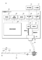
図1は、内視鏡システム10の構成を説明する説明図である。内視鏡システム10は、内視鏡用プロセッサ20、内視鏡40、表示装置16および入力装置17を備える。内視鏡用プロセッサ20は、制御部21、主記憶装置22、補助記憶装置23、通信部24、表示装置I/F(Interface)26、入力装置I/F27、光源28、調光部30、内視鏡用コネクタ29およびバスを備える。
図1は、内視鏡システム10の構成を説明する説明図である。内視鏡システム10は、内視鏡用プロセッサ20、内視鏡40、表示装置16および入力装置17を備える。内視鏡用プロセッサ20は、制御部21、主記憶装置22、補助記憶装置23、通信部24、表示装置I/F(Interface)26、入力装置I/F27、光源28、調光部30、内視鏡用コネクタ29およびバスを備える。
内視鏡40は、挿入部44、操作部43、ユニバーサルコード49およびスコープコネクタ48を備える。挿入部44は長尺であり、一端が折止部を介して操作部43に接続されている。挿入部44は、操作部43側から順に軟性部441、湾曲部442および先端部443を有する。湾曲部442は、操作部43に設けられた湾曲ノブの操作に応じて湾曲する。
ユニバーサルコード49は長尺であり、第一端が操作部43に、第二端がスコープコネクタ48にそれぞれ接続されている。ユニバーサルコード49は、軟性である。スコープコネクタ48は略直方体形状である。スコープコネクタ48は、信号伝達用コネクタと、照明光コネクタとを含む。内視鏡40には、図示を省略する送気送水ポンプが接続される。
制御部21は、本実施の形態のプログラムを実行する演算制御装置である。制御部21には、一または複数のCPU(Central Processing Unit)またはマルチコアCPU等が使用される。制御部21は、バスを介して内視鏡用プロセッサ20を構成するハードウェア各部と接続されている。
表示装置16は、たとえば液晶表示装置、または、有機EL(Electro Luminescence)表示装置である。入力装置17は、たとえばキーボード、タッチパネルまたはフットスイッチ等である。
主記憶装置22は、SRAM(Static Random Access Memory)、DRAM(Dynamic Random Access Memory)、またはフラッシュメモリ等の記憶装置である。主記憶装置22には、制御部21が行なう処理の途中で必要な情報および制御部21で実行中のプログラムが一時的に保存される。
補助記憶装置23は、SRAM、フラッシュメモリまたはハードディスク等の記憶装置である。補助記憶装置23には、制御部21に実行させるプログラム、およびプログラムの実行に必要な各種データが保存される。
通信部24は、内視鏡用プロセッサ20とネットワークとの間のデータ通信を行なうインターフェイスである。表示装置I/F26は、内視鏡用プロセッサ20と表示装置16とを接続するインターフェイスである。入力装置I/F27は、内視鏡用プロセッサ20と入力装置17とを接続するインターフェイスである。
光源28は、たとえばLED(Light Emitting Diode)等の高輝度光源である。光源28は、たとえばキセノンランプ等の広帯域光を発する光源と、光フィルタとの組み合わせであってもよい。光源28は、先端部443に内蔵された照明用LEDであってもよい。
光源28は、図示を省略するドライバを介してバスに接続されている。光源28の点灯、消灯、明るさの変更および色の変更は、制御部21により制御される。光源28から照射した照明光は、内視鏡用コネクタ29およびスコープコネクタ48を介して内視鏡40に供給される。照明光は、内視鏡40内部の照明用光ファイバーにより、先端部443に設けられた照明窓52(図2参照)に導光される。
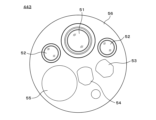
図2は、先端部443の端面の外観図である。先端部443の先端に、観察窓51、2個の照明窓52、送気ノズル53、送水ノズル54およびチャンネル出口55等が配置されている。
なお、図2は先端部443の端面の外観の一例であり、各部材の配置は図2に限定されない。たとえば、送気ノズル53および送水ノズル54の配置は、逆であっても良い。照明窓52は、1個または3個以上でも良い。内視鏡40は、視野方向を挿入部44の側方に向けた側視型、または斜視型等であってもよい。
図3は、調光部30の構成および機能を説明する説明図である。調光部30は、調光出力部31および測光部32を備える。測光部32は、輝度指標取得部33および生成部34を備える。
照明窓52から照射された照明光により、観察視野が照明される。たとえば観察視野内の生体組織で反射した反射光が、観察窓51および図示を省略する観察光学系を介して、撮像素子46に結像する。撮像素子46により生成された撮像信号が、スコープコネクタ48を介して内視鏡用プロセッサ20に伝送される。スコープコネクタ48が接続された内視鏡用コネクタ29は、撮像素子46から撮像信号を取得する撮像信号取得部の機能を果たす。
以下の説明では、R(Red:赤)、G(Green:緑)、B(Blue:青)の三色のカラー信号を出力する、いわゆる原色系の撮像素子46を使用する内視鏡システム10を例にして説明する。青色は、第1色の例示である。緑色は、第1色よりも波長が長い第2色の例示である。なお、原色系の代わりに補色系の撮像素子46が使用されてもよい。
制御部21は、撮像信号に基づいて画像処理を行ない、内視鏡検査に適した画質の内視鏡画像61(図8A参照)を表示装置16に出力する。輝度指標取得部33は、撮像信号に基づいて輝度指標を取得する。輝度指標は、撮像素子46により撮影された画像の輝度に関する指標である。従来の調光部30においては、画像のB成分の輝度に関する指標が使用される場合が多い。輝度指標の詳細については後述する。
生成部34は、輝度指標に基づいて測光信号を生成し、調光出力部31に出力する。調光出力部31は、測光信号と、内視鏡40の機種と、ユーザが設定した動作モードとに基づいて調光信号を生成し、光源28に出力する。動作モードは、たとえば通常光観察モードと、特殊光観察モードである。光源28は、調光信号に基づく明るさおよび色の照明光を放射する。
以上のループにより、照明光の明るさ等をリアルタイムで自動的に調整する自動調光が行なわれる。調光部30は、たとえばASIC(Application Specific Integrated Circuit)等のカスタムIC(Integrated Circuit)、またはFPGA(Field-Programmable Gate Array)等のPLD(Programmable Logic Device)である。調光部30は、本実施の形態の自動調光用に設計された専用ICチップであってもよい。
調光部30を構成する調光出力部31、測光部32、輝度指標取得部33および生成部34は、それぞれIC内部に構成された論理回路である。ハードウェアにより高速に調光を行なうことにより、観察視野の変化に調光機能が速やかに追随する内視鏡システム10を提供できる。
調光部30は、光源制御用のドライバICと一体に構成されていてもよい。調光部30は、制御部21と一体のICチップに構成されていてもよい。制御部21およびバスの速度が十分に高速である場合には、調光部30の処理は制御部21によりソフトウェア的に実現されてもよい。
図4は、先端部443と生体組織との距離が撮像信号に及ぼす影響を説明する図である。図4は、先端部443と生体組織との距離の影響を模式的に示す。ハッチングした部分は、生体組織を示す。
「強い接触」は、先端部443が生体組織に押し付けられた状態である。照明窓52から放射された照明光は、生体組織の内部を伝搬して、観察窓51に到達する。「軽い接触」は、先端部443と生体組織とが軽く接触し、表面張力により両者の間に粘液または水等の液体の層が発生している状態である。照明窓52から放射された照明光は、液体層の内部および生体組織の表層部を伝搬して、観察窓51に到達する。
「軽い接触」および「強い接触」の状態では、照明光のエネルギーの大部分は生体組織に吸収されるため、観察窓51に到達する光は僅かである。照明光が明るい状態に設定された場合であっても、撮像素子46により撮影された画像は、暗いままである。
「近接」は、先端部443が観察光学系の合焦範囲よりも生体組織に近づいた状態である。「近接」の状態では、内視鏡画像61はいわゆる「ピンボケ」の状態になる。「中距離」は、内視鏡40により生体組織の状態を詳細に観察できる状態である。「遠距離」は、内視鏡40により生体組織の広い範囲を観察できる状態である。医師は、通常は「遠距離」または「中距離」の状態になるように内視鏡40を操作して、内視鏡検査を行なう。
「近接」「中距離」および「遠距離」の状態では、照明窓52から放射された照明光は、生体組織の表面で反射して、観察窓51に到達する。照明光の明るさの変化が、撮像素子46により撮影された画像の明るさに直接的に反映される。
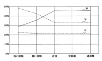
図5は、先端部443と生体組織との距離が撮像信号に及ぼす影響を説明するグラフである。図5の横軸は、図4を使用して説明したそれぞれの状態である。縦軸は、撮像素子46により撮影された画像を構成するR、G、Bそれぞれの色の成分比である。一点鎖線はR成分、破線はG成分、実線はB成分の比率をそれぞれ示す。
「近接」、「中距離」および「遠距離」では、成分比はほぼ一定であり、多い方からB成分、G成分、R成分の順である。R成分の比率は、「軽い接触」および「強い接触」でも殆ど変化しない。「軽い接触」では、G成分がB成分よりも多くなっている。「強い接触」では、G成分の比率がさらに上昇している。
本実施の形態の内視鏡システム10が行なう自動調光の概要を説明する。G成分よりもB成分が大きい場合、生成部34はB成分に関する輝度指標に基づいて測光信号を生成する。測光信号が、所定の基準よりも明るい画像が撮影されたことを示している場合、調光出力部31は光源28の出力を低下させる調光信号を出力する。測光信号が、所定の基準よりも暗い画像が撮影されたことを示している場合、調光出力部31は光源28の出力を上昇させる調光信号を出力する。
先端部443は生体組織に接触しておらず、自動調光による照明光の明るさの変化が、撮像素子46により撮影された画像の明るさに直接的に反映される。したがって、観察視野の状態が変化した場合であっても、照明光の明るさが速やかに調整され、医師は内視鏡検査をスムーズに続けられる。
G成分がB成分よりも大きい場合、先端部443が生体組織に接触している。そのため、自動調光による照明光の明るさの変化が、撮像素子46により撮影された画像の明るさに十分に反映されない。このような状態で、B成分の輝度に基づいて自動調光が行なわれた場合、自動調光機能は適切な動作を行なわず、光源28は最大出力で動作し続ける状態になる。
光源28が最大出力での動作を長時間継続した場合、光源28の寿命が縮まってしまう。光源28の発熱により、内視鏡用プロセッサ20の内部が熱くなるため、制御部21および調光部30等の電子部品の誤動作および故障を引き起こしやすい。光源28の消費電力が不必要に増大する問題もある。照明窓52から放射される光が不必要に強いため、生体組織に悪影響を与えるおそれもある。
以上に列挙したような問題の発生を防止するため、本実施の形態の生成部34は、G成分がB成分よりも大きい場合、輝度指標に対して大きな測光信号、すなわち撮像素子46により撮影された画像が、実際よりも明るい場合であるときと同様の測光信号を出力する。調光出力部31は、測光信号に基づいて動作する。そのため、光源28の出力が不必要に上昇せず、上述の種々の問題の発生を防止できる。
輝度指標の具体例を説明する。輝度指標は、たとえば撮像素子46が撮影した画像全面におけるG、Bそれぞれの平均輝度である。輝度指標は、撮像素子46が撮影した画像のうちの所定の領域におけるG、Bそれぞれの平均輝度であってもよい。以下の説明では、輝度指標の算出に使用する所定の領域を、測光領域と記載する場合がある。
測光領域は、たとえば画像の中央部である。測光領域は、画像の中心と縁との中間付近の領域であってもよい。制御部21は、医師による測光領域の指定を受け付けて、調光部30に指示してもよい。制御部21は、たとえばAI(Artificial Intelligence)により検出された病変部を測光領域に設定して、調光部30に指示してもよい。
平均輝度の代わりに、たとえば輝度のメジアン値または中央値等の統計値が、輝度指標に使用されてもよい。制御部21は、輝度指標の算出方法の指定を受け付けて調光部30に指示してもよい。
輝度指標に基づいて測光信号を生成する生成部34の動作の具体例を説明する。生成部34は、たとえば(1)式に基づいて算出した測光信号を出力する。
M=PB+K×PG ‥‥‥ (1)
Mは、測光信号である。
PBは、Bに関する輝度指標である。
PGは、Gに関する輝度指標である。
Kは、係数である。
M=PB+K×PG ‥‥‥ (1)
Mは、測光信号である。
PBは、Bに関する輝度指標である。
PGは、Gに関する輝度指標である。
Kは、係数である。
(1)式におけるPBは、第1色の輝度に関する第1指標の例示であり、PGは第2色の輝度に関する第2指標の例示である。
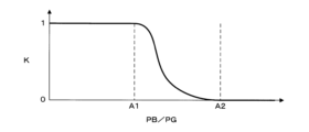
図6は、係数Kを説明するグラフである。図6の横軸は、Bに関する輝度指標PBを、Gに関する輝度指標PGで除した値を示す。図6の縦軸は係数Kを示す。PB/PGが閾値A1未満である場合、係数Kは1である。PB/PGが閾値A2以上である場合、係数Kは0である。PB/PGがA1以上A2未満の範囲で、係数Kは1から0までなだらかに変化する。
たとえば、閾値A1は1.0であり、閾値A2は1.3である。PB/PGが閾値A1未満である領域は、図5においてB成分がG成分よりも小さい範囲であり、先端部443と生体組織とが接触している領域である。PB/PGが閾値A2以上である領域は、図5においてB成分がG成分の1.3倍以上の領域であり、先端部443と生体組織とが接触していない領域である。
したがって、(1)式に基づいて算出される測光信号は、先端部443と生体組織とが接触している場合には(PB+PG)であり、先端部443と生体組織とが接触していない場合にはPBである。先端部443の一部分が生体組織と接触している等、接触と非接触との中間の状態では、接触時と非接触時の中間の測光信号が算出される。
以上により、先端部443と生体組織とが接触している場合の光源28の出力を低減する内視鏡システム10を提供できる。図6に示すように係数Kが0と1との間でなだらかに変化するため、先端部443の一部分が生体組織に接触している場合、および接触範囲が変動している場合等に、光源28の出力の急激な変動を回避できる。したがって、内視鏡画像の明るさの急激な変動を防止する内視鏡システム10を提供できる。
生成部34は、たとえば(2)式に基づいて算出した測光信号を出力してもよい。
M=PB+K×(PG+PR) ‥‥‥ (2)
PRは、Rに関する輝度指標である。
(2)式を用いる場合、(1)式を用いる場合に比べて先端部443と生体組織とが接触している場合に生成部34から出力される測光信号が大きくなる。したがって、先端部443と生体組織とが接触している場合の光源28の出力をさらに低減する内視鏡システム10を提供できる。
M=PB+K×(PG+PR) ‥‥‥ (2)
PRは、Rに関する輝度指標である。
(2)式を用いる場合、(1)式を用いる場合に比べて先端部443と生体組織とが接触している場合に生成部34から出力される測光信号が大きくなる。したがって、先端部443と生体組織とが接触している場合の光源28の出力をさらに低減する内視鏡システム10を提供できる。
生成部34は、たとえば(3)式に基づいて算出した測光信号を出力してもよい。
M=(1-K)PB+K×PG ‥‥‥ (3)
(3)式によると、(1-K)は測光信号Mに対するB成分の寄与率を、Kは測光信号Mに対するG成分の寄与率をそれぞれ示し、両者の使用率の合計は100パーセントである。
M=(1-K)PB+K×PG ‥‥‥ (3)
(3)式によると、(1-K)は測光信号Mに対するB成分の寄与率を、Kは測光信号Mに対するG成分の寄与率をそれぞれ示し、両者の使用率の合計は100パーセントである。
生成部34は、たとえば(4)式に基づいて算出した測光信号を出力してもよい。

(4)式によると、PBがPGよりも大きい場合の測光信号Mは、B成分に関する輝度指標であり、PBがPG以下である場合の測光信号MはG成分に関する輝度指標である。(4)式は、図5を使用して説明したグラフにおいて、Bに関する輝度指標PBがGに関する輝度指標PGよりも大きい場合には輝度指標PBを測光指標Mに使用し、輝度使用PBが輝度指標PG以下である場合には、輝度指標PGを測光指標Mに使用することを意味する。
すなわち(4)式は、PBがPG以下である場合に、先端部443と生体組織とが接触していると判定し、PGを測光信号Mに用いる動作を意味する。
生成部34は、たとえば(5)式に基づいて算出した測光信号を出力してもよい。

(5)式は、PBがPG以下である場合に、先端部443と生体組織とが接触していると判定し、(PG+PR)を測光信号Mに用いる動作を意味する。
(1)式から(5)式で例示した測光信号の算出式はいずれも例示であり、これらに限定されるものではない。たとえば、生成部34は、(1)式から(5)式の左辺に、任意の定数を積算した値を測光信号に使用してもよい。生成部34は、たとえば内視鏡40の機種、または、使用中の動作モード等の条件に応じて、使用する算出式を切り替えてもよい。
(1)式から(5)式で例示した測光信号の算出式によると、PBがPG以下である場合には、PBがPGを超える場合に比べて、PGの寄与度が高い測光信号が算出される。
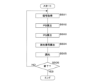
図7は、調光部30の動作の流れを説明するフローチャートである。図7を使用して説明する処理と並行して、制御部21は撮像素子46から取得した撮像信号に基づいて画像処理を行なって生成した内視鏡画像を、表示装置16に表示する。たとえば、医師が通常光観察から特殊光観察へ動作モードを変更する操作を行なった場合、制御部21は動作モードの変更を調光部30に通知する。内視鏡画像の生成等の、制御部21が行なう処理は、公知であるため説明を省略する。
調光部30は、撮像素子46から撮像信号を取得する(ステップS501)。輝度指標取得部33は、撮像信号に基づいてBに関する輝度指標PBを算出する(ステップS502)。輝度指標取得部33は、撮像信号に基づいてGに関する輝度指標PGを算出する(ステップS503)。生成部34は、たとえば(1)式から(4)式に例示した算出式に基づいて測光信号Mを算出する(ステップS504)。
調光出力部31は、測光信号と、制御部21から指示された動作モードとに基づいて調光信号を出力する(ステップS505)。たとえば、動作モードが通常光観察モードである場合、調光出力部31は測光信号に応じた輝度の白色光を放射させる調光信号を光源28に出力する。同様に、動作モードが特殊光観察モードである場合、調光出力部31は測光信号に応じた輝度の狭帯域光を放射させる調光信号を光源28に出力する。
調光部30は、処理を終了するか否かを判定する(ステップS506)。たとえば、医師が照明光の停止操作を行なった場合、調光部30は処理を終了すると判定する。処理を終了しないと判定した場合(ステップS506でNO)、調光部30はステップS501に戻る。処理を終了すると判定した場合(ステップS506でYES)、調光部30は処理を終了する。
本実施の形態によると、内視鏡40の先端が生体組織に近接または接触している場合であっても、自動調光機能が適切に動作して、光源28の出力が大きくなり過ぎることを防止する内視鏡システム10を提供できる。
図3を使用して説明した調光部30における調光出力部31および光源28の動作は、従来から使用されている自動調光機能と同様である。したがって、従来の調光部30に対して比較的わずかな設計変更で、自動調光機能の動作を改善した内視鏡用プロセッサ20を実現できる。
[実施の形態2]
本実施の形態は、撮像素子46の端部の画像に基づいて先端部443と生体組織との接触の有無を判定する内視鏡システム10に関する。実施の形態1と共通する部分については、説明を省略する。
本実施の形態は、撮像素子46の端部の画像に基づいて先端部443と生体組織との接触の有無を判定する内視鏡システム10に関する。実施の形態1と共通する部分については、説明を省略する。
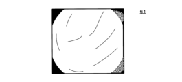
図8Aおよび図8Bは、実施の形態2の接触判定方法を説明する説明図である。図8Aは、先端部443が生体組織に接触していない場合の内視鏡画像61を模式的に示す。四隅の黒い部分は、撮像光学系の鏡枠により、いわゆる画像ケラレが生じている部分を示す。
図8Bは、先端部443と生体組織とが接触している場合の内視鏡画像61を模式的に示す。粘液による光の屈折等による迷光が生じて、内視鏡画像61の右上および右下の隅部が明るくなっている。
画像ケラレの生じ方は、撮像素子46と鏡枠との組付状態のばらつきの影響を受けやすい。制御部21は、画像ケラレが生じる可能性のある領域に対して電子的なマスク処理を施した内視鏡画像61を表示装置16に表示する。マスク処理により、内視鏡画像61の四隅の態様の個体差が防止されている。
図8Bに示すように隅部が明るい状態の内視鏡画像61が撮影された場合であっても、制御部21は、四隅を黒色にした状態の内視鏡画像61を表示装置16に表示する。したがって、四隅の明るさの変化に医師等のユーザが気付くことはない。
本実施の形態の内視鏡システム10は、通常はマスク処理されている四隅のデータを用いて、先端部443と生体組織との接触の有無を判定する。
図9は、実施の形態2のプログラムの処理の流れを説明するフローチャートである。制御部21は、撮像素子46から撮像信号を取得する(ステップS601)。制御部21は、撮像信号に対して公知の信号処理を行ない、内視鏡画像61を生成する(ステップS602)。制御部21は、四隅にマスク処理を行なった内視鏡画像61を、表示装置16に表示する(ステップS603)。
制御部21は、接触判定のサブルーチンを起動する(ステップS604)。接触判定のサブルーチンは、先端部443と生体組織とが接触しているか否かを判定するサブルーチンである。接触判定のサブルーチンの処理の流れは後述する。
制御部21は、接触判定のサブルーチンにより接触していると判定されたか否かを判定する(ステップS605)。接触していないと判定した場合(ステップS605でNO)、制御部21は調光部30に調光を指示する(ステップS606)。調光部30は、たとえば従来から行なわれているように撮像信号のB成分の輝度に基づいて光源28の明るさを調整する調光を行なう。調光部30は、実施の形態1と同様の動作を行なってもよい。
接触していると判定した場合(ステップS605でYES)、または、ステップS606の終了後、制御部21は処理を終了するか否かを判定する(ステップS607)。たとえば、医師が照明光の停止操作を行なった場合、制御部21は処理を終了すると判定する。処理を終了しないと判定した場合(ステップS607でNO)、制御部21はステップS601に戻る。処理を終了すると判定した場合(ステップS607でYES)、制御部21は処理を終了する。
図10は、接触判定のサブルーチンの処理の流れを説明するフローチャートである。接触判定のサブルーチンは、先端部443と生体組織とが接触しているか否かを判定するサブルーチンである。接触判定のサブルーチンにより、制御部21は本実施の形態の接触判定部の機能を実現する。
制御部21は、マスク処理を行なう前の内視鏡画像61に基づいて、四隅それぞれの領域の輝度を算出する(ステップS611)。たとえば、制御部21は、内視鏡40を製造する際のばらつきに関わらず必ずケラレが発生する領域の画素の輝度の平均値を算出する。制御部21は、内視鏡検査を行なう前に実施されたホワイトバランス調整時の内視鏡画像61においてケラレが発生している領域の輝度を算出してもよい。輝度は、たとえばR、G、Bいずれか一色または二色の輝度であってもよい。平均値の代わりに、メジアン値または中央値等の任意の統計値が使用されてもよい。
制御部21は、四隅それぞれの輝度が所定の閾値を超えるか否かを判定する(ステップS612)。いずれの隅部の輝度も所定の閾値を超えていると判定した場合(ステップS612でYES)、制御部21は、接触状態の判定結果は「接触」であると判定する(ステップS613)。所定の閾値を超えていない隅部があると判定した場合(ステップS612でNO)、制御部21は、接触状態の判定結果は「非接触」であると判定する(ステップS614)。ステップS613またはステップS614の終了後、制御部21は処理を終了する。
なお、ステップS612において制御部21は、3個以下の隅部の輝度が所定の閾値を超えるか否かを判定してもよい。先端部443の極一部分だけが生体組織に接触している場合であっても、検出する内視鏡システム10を実現できる。
本実施の形態によると、先端部443と生体組織とが接触している場合には調光を行なわないため、接触により内視鏡画像が暗くなっている状態での光源28の出力上昇を防止する内視鏡システム10を提供できる。
なお、調光部30が接触判定のサブルーチンで説明した接触判定を行ない、調光動作の実行可否を判定してもよい。
[実施の形態3]
本実施の形態は、通常モードと、暗い場所の撮影に適した暗所モードとを切替可能な内視鏡システム10に関する。実施の形態2と共通する部分については、説明を省略する。
本実施の形態は、通常モードと、暗い場所の撮影に適した暗所モードとを切替可能な内視鏡システム10に関する。実施の形態2と共通する部分については、説明を省略する。
図11は、実施の形態3のプログラムの処理の流れを説明するフローチャートである。ステップS605までの処理は、図9を使用して説明した実施の形態2のプログラムの処理の流れと同一であるため、説明を省略する。
接触していると判定した場合(ステップS605でYES)、制御部21は内視鏡システム10を暗所モードに設定する(ステップS621)。暗所モードは、暗い場所での観察に適した動作モードである。接触していないと判定した場合(ステップS605でNO)、制御部21は内視鏡システム10を通常モードに設定する(ステップS622)。通常モードは、通常の内視鏡検査に適した動作モードである。
暗所モードと通常モードの相違について説明する。暗所モードは、たとえば撮像素子46のアナログゲインを通常モードに比べて高くしたモード、または、電子シャッターの速度を通常モードに比べて遅くしたモードである。暗所モードは、アナログゲインと電子シャッター速度の両方が通常モードから変更されたモードであってもよい。ステップS621およびステップS622により、制御部21は撮像素子46の設定を制御する素子制御部の機能を実現する。
具体例を挙げて説明する。通常モードでのアナログゲインは1倍であり、暗所モードでのアナログゲインは通常モードに比べて大きい4倍である。通常モードでの電子シャッターの速度は、1/240秒であり、暗所モードでの電子シャッターの速度は通常モードに比べて遅い1/60秒である。
ステップS621またはステップS622の終了後、制御部21は調光部30に調光を指示する(ステップS623)。調光部30は、たとえば従来から行なわれているように撮像信号のB成分の輝度に基づいて光源28の明るさを調整する調光を行なう。なお、暗所モードに設定されている場合、調光部30は通常モードに比べて照明光を暗くするような調光信号を出力する。
制御部21は処理を終了するか否かを判定する(ステップS624)。たとえば、医師が照明光の停止操作を行なった場合、制御部21は処理を終了すると判定する。処理を終了しないと判定した場合(ステップS624でNO)、制御部21はステップS601に戻る。処理を終了すると判定した場合(ステップS624でYES)、制御部21は処理を終了する。
なお、フローチャートの記載を省略するが、通常モードと暗所モードとの間の切替が行なわれた場合、アナログゲインまたは電子シャッターは3秒程度の時間をかけて徐々に切り替えられることが望ましい。内視鏡画像61が急激に変化することによるユーザの違和感を防止した内視鏡システム10を提供できる。
本実施の形態によると、先端部443と生体組織とが接触している場合に、内視鏡システム10は暗所モードに設定される。暗所モードでは、調光部30は通常モードに比べて照明光を暗くするような調光信号を出力するため、接触により内視鏡画像61が暗くなっている状態での光源28の出力上昇を防止する内視鏡システム10を提供できる。
[変形例3-1]
制御部21は、図10を使用して説明した接触判定のサブルーチンを起動する代わりに、実施の形態1の(5)式で説明したように、PBがPG以下である場合に、先端部443と生体組織とが接触していると判定してもよい。
制御部21は、図10を使用して説明した接触判定のサブルーチンを起動する代わりに、実施の形態1の(5)式で説明したように、PBがPG以下である場合に、先端部443と生体組織とが接触していると判定してもよい。
[変形例3-2]
制御部21は、実施の形態1で説明したPB/PGが1を下回った場合に、内視鏡システム10を徐々に暗所モードに切り替え、PB/PGが2を上回った場合に内視鏡システム10を徐々に通常モードに切り替えてもよい。先端部443と生体組織領域とが、接触するかしないか微妙な状態が継続している場合に、暗所モードと通常モードとの切り替えが頻繁に行なわれることを防止した内視鏡システム10を提供できる。
制御部21は、実施の形態1で説明したPB/PGが1を下回った場合に、内視鏡システム10を徐々に暗所モードに切り替え、PB/PGが2を上回った場合に内視鏡システム10を徐々に通常モードに切り替えてもよい。先端部443と生体組織領域とが、接触するかしないか微妙な状態が継続している場合に、暗所モードと通常モードとの切り替えが頻繁に行なわれることを防止した内視鏡システム10を提供できる。
[実施の形態4]
本実施の形態は、先端部443と生体組織とが接触している場合に、照明光の成分を変更する内視鏡システム10に関する。実施の形態3と共通する部分については、説明を省略する。
本実施の形態は、先端部443と生体組織とが接触している場合に、照明光の成分を変更する内視鏡システム10に関する。実施の形態3と共通する部分については、説明を省略する。
図12は、実施の形態4のプログラムの処理の流れを説明するフローチャートである。ステップS605までの処理は、図9を使用して説明した実施の形態2のプログラムの処理の流れと同一であるため、説明を省略する。
接触していると判定した場合(ステップS605でYES)、制御部21は調光部30に接触モードでの調光を指示する(ステップS631)。接触していないと判定した場合(ステップS605でNO)、制御部21は通常モードでの調光を制御部21に指示する(ステップS632)。
ステップS631またはステップS632の終了後、制御部21は処理を終了するか否かを判定する(ステップS624)。終了しないと判定した場合(ステップS624でNO)、制御部21はステップS601に戻る。終了すると判定した場合(ステップS624でYES)、制御部21は処理を終了する。
接触モードでの調光と通常モードでの調光との相違について説明する。接触モードは、通常モードに比べて短波長の光の成分が少ない照明光を光源28に出力させるモードである。特殊光観察を行なう場合を例にして説明する。通常モード時の光源28は、紫色の光と、緑色の光とを、エネルギー比で4:1の割合で混合した光を放射する。接触モード時の光源28は、紫色の光と、緑色の光とを、エネルギー比で2:1の割合で混合した光を放射する。
紫色の光と、緑色の光とを、エネルギー比で4:1の割合で混合した照明光は、第1成分比の照明光の例示である。紫色の光と、緑色の光とを、エネルギー比で2:1の割合で混合した照明光は、短波長成分である紫色の光割合を第1成分比に比べて低くした、第2成分比の照明光の例示である。
生体組織に吸収されやすい紫色の光の比率を低くすることで、先端部443と生体組織が接触している場合であっても撮像素子46に入射する光量の減少幅を抑えることができる。したがって、先端部443と生体組織が接触している場合であっても、光源28の出力上昇を防止する内視鏡システム10を提供できる。
[変形例4-1]
制御部21は、実施の形態1で説明したPB/PGが1を下回った場合に、内視鏡システム10を徐々に接触モードに切り替え、PB/PGが2を上回った場合に内視鏡システム10を徐々に通常モードに切り替えてもよい。
制御部21は、実施の形態1で説明したPB/PGが1を下回った場合に、内視鏡システム10を徐々に接触モードに切り替え、PB/PGが2を上回った場合に内視鏡システム10を徐々に通常モードに切り替えてもよい。
各実施例で記載されている技術的特徴(構成要件)はお互いに組合せ可能であり、組み合わせすることにより、新しい技術的特徴を形成することができる。
今回開示された実施の形態はすべての点で例示であって、制限的なものでは無いと考えられるべきである。本発明の範囲は、上記した意味では無く、請求の範囲によって示され、請求の範囲と均等の意味および範囲内でのすべての変更が含まれることが意図される。
今回開示された実施の形態はすべての点で例示であって、制限的なものでは無いと考えられるべきである。本発明の範囲は、上記した意味では無く、請求の範囲によって示され、請求の範囲と均等の意味および範囲内でのすべての変更が含まれることが意図される。
10 内視鏡システム
16 表示装置
17 入力装置
20 内視鏡用プロセッサ
21 制御部
22 主記憶装置
23 補助記憶装置
24 通信部
26 表示装置I/F
27 入力装置I/F
28 光源
29 内視鏡用コネクタ
30 調光部
31 調光出力部
32 測光部
33 輝度指標取得部
34 生成部
40 内視鏡
43 操作部
44 挿入部
441 軟性部
442 湾曲部
443 先端部
46 撮像素子
48 スコープコネクタ
49 ユニバーサルコード
51 観察窓
52 照明窓
53 送気ノズル
54 送水ノズル
55 チャンネル出口
61 内視鏡画像
16 表示装置
17 入力装置
20 内視鏡用プロセッサ
21 制御部
22 主記憶装置
23 補助記憶装置
24 通信部
26 表示装置I/F
27 入力装置I/F
28 光源
29 内視鏡用コネクタ
30 調光部
31 調光出力部
32 測光部
33 輝度指標取得部
34 生成部
40 内視鏡
43 操作部
44 挿入部
441 軟性部
442 湾曲部
443 先端部
46 撮像素子
48 スコープコネクタ
49 ユニバーサルコード
51 観察窓
52 照明窓
53 送気ノズル
54 送水ノズル
55 チャンネル出口
61 内視鏡画像
Claims (14)
- 撮像素子から撮像信号を取得する撮像信号取得部と、
前記撮像信号に基づいて観察視野を照明する光源を制御する調光部とを備え、
前記調光部は、
前記撮像信号に基づいて、第1色の輝度に関する第1指標および第2色の輝度に関する第2指標を取得する輝度指標取得部と、
前記第1指標および前記第2指標に基づいて測光信号を生成する生成部と、
前記測光信号に基づいて、前記光源に対して調光信号を出力する調光出力部とを有する
内視鏡用プロセッサ。 - 前記生成部は、
前記第1指標が前記第2指標に比べて小さい場合には、前記第1指標が前記第2指標に比べて大きい場合に比べて、前記第2指標の寄与度が高い前記測光信号を生成する
請求項1に記載の内視鏡用プロセッサ。 - 前記生成部は、
前記第1指標が前記第2指標に比べて大きい場合、前記第1指標を前記測光信号に使用し、
前記第1指標が前記第2指標に比べて小さい場合、前記第1指標よりも大きい前記測光信号を生成する
請求項1に記載の内視鏡用プロセッサ。 - 前記第1指標が前記第2指標に比べて小さい場合、内視鏡の先端が生体組織に接触していると判定する接触判定部を備える
請求項1に記載の内視鏡用プロセッサ。 - 前記撮像素子の設定を制御する素子制御部を備え、
前記接触判定部が接触していないと判定した場合、前記素子制御部は、前記撮像素子を通常の撮影に使用する通常モードに設定し、
前記接触判定部が接触していると判定した場合、前記素子制御部は、前記撮像素子を通常モードよりも暗い場所の撮影に適した暗所モードに設定する
請求項4に記載の内視鏡用プロセッサ。 - 前記撮像信号に基づいて、前記撮像素子の隅部の輝度が所定の輝度よりも明るい場合、内視鏡の先端が生体組織に接触していると判定する接触判定部を備える
請求項1に記載の内視鏡用プロセッサ。 - 前記撮像素子の設定を制御する素子制御部を備え、
前記接触判定部が接触していないと判定した場合、前記素子制御部は、前記撮像素子を通常の撮影に使用する通常モードに設定し、
前記接触判定部が接触していると判定した場合、前記素子制御部は、前記撮像素子を通常モードよりも暗い場所の撮影に適した暗所モードに設定する
請求項6に記載の内視鏡用プロセッサ。 - 前記暗所モードはアナログゲインが、前記通常モードに比べて高いモードである
請求項7に記載の内視鏡用プロセッサ。 - 前記暗所モードは、電子シャッターのシャッター速度が前記通常モードに比べて遅いモードである
請求項7に記載の内視鏡用プロセッサ。 - 前記接触判定部が接触していないと判定した場合、前記生成部は、前記第1指標を前記測光信号に使用し、
前記接触判定部が接触していると判定した場合、前記生成部は、前記第1指標よりも大きい前記測光信号を生成する
請求項4に記載の内視鏡用プロセッサ。 - 前記接触判定部が接触していないと判定した場合、前記調光部は所定の第1成分比の照明光を照射させる調光信号を出力し、
前記接触判定部が接触していると判定した場合、前記調光部は前記第1成分比に比べて短波長成分の割合を低くした第2成分比の照明光を照射させる調光信号を出力する
請求項4から請求項10のいずれか一つに記載の内視鏡用プロセッサ。 - 前記第1色の波長は、前記第2色の波長よりも短い
請求項1に記載の内視鏡用プロセッサ。 - 前記第1色は青であり、
前記第2色は緑である
請求項12に記載の内視鏡用プロセッサ。 - 撮像素子から撮像信号を取得し、
前記撮像信号に基づいて、第1色の輝度に関する第1指標および第2色の輝度に関する第2指標を取得し、
前記第1指標および前記第2指標に基づいて測光信号を生成し、
前記測光信号に基づいて、調光信号を出力し、
前記調光信号に基づいて観察視野を照明する光源を制御する
処理を内視鏡用プロセッサの制御部が実行する内視鏡用プロセッサの制御方法。
Priority Applications (1)
| Application Number | Priority Date | Filing Date | Title |
|---|---|---|---|
| US18/833,571 US20250098950A1 (en) | 2022-05-10 | 2023-04-20 | Processor for endoscope and method of controlling processor for endoscope |
Applications Claiming Priority (2)
| Application Number | Priority Date | Filing Date | Title |
|---|---|---|---|
| JP2022-077751 | 2022-05-10 | ||
| JP2022077751A JP7753152B2 (ja) | 2022-05-10 | 2022-05-10 | 内視鏡用プロセッサおよび内視鏡用プロセッサの制御方法 |
Publications (1)
| Publication Number | Publication Date |
|---|---|
| WO2023218897A1 true WO2023218897A1 (ja) | 2023-11-16 |
Family
ID=88730254
Family Applications (1)
| Application Number | Title | Priority Date | Filing Date |
|---|---|---|---|
| PCT/JP2023/015794 Ceased WO2023218897A1 (ja) | 2022-05-10 | 2023-04-20 | 内視鏡用プロセッサおよび内視鏡用プロセッサの制御方法 |
Country Status (3)
| Country | Link |
|---|---|
| US (1) | US20250098950A1 (ja) |
| JP (1) | JP7753152B2 (ja) |
| WO (1) | WO2023218897A1 (ja) |
Citations (1)
| Publication number | Priority date | Publication date | Assignee | Title |
|---|---|---|---|---|
| WO2017073302A1 (ja) * | 2015-10-27 | 2017-05-04 | オリンパス株式会社 | 撮像システムのための制御装置、撮像システム、及び撮像システムの制御方法 |
-
2022
- 2022-05-10 JP JP2022077751A patent/JP7753152B2/ja active Active
-
2023
- 2023-04-20 US US18/833,571 patent/US20250098950A1/en active Pending
- 2023-04-20 WO PCT/JP2023/015794 patent/WO2023218897A1/ja not_active Ceased
Patent Citations (1)
| Publication number | Priority date | Publication date | Assignee | Title |
|---|---|---|---|---|
| WO2017073302A1 (ja) * | 2015-10-27 | 2017-05-04 | オリンパス株式会社 | 撮像システムのための制御装置、撮像システム、及び撮像システムの制御方法 |
Also Published As
| Publication number | Publication date |
|---|---|
| JP7753152B2 (ja) | 2025-10-14 |
| JP2023166896A (ja) | 2023-11-22 |
| US20250098950A1 (en) | 2025-03-27 |
Similar Documents
| Publication | Publication Date | Title |
|---|---|---|
| CN104080393B (zh) | 光源装置以及光源装置的调光方法 | |
| CN103429136B (zh) | 内窥镜装置 | |
| US11044416B2 (en) | Endoscope system, processor device, and endoscope system operation method | |
| EP2926718A1 (en) | Endoscope system and method for operating endoscope system | |
| CN106163372B (zh) | 内窥镜系统及其工作方法 | |
| CN108463157B (zh) | 内窥镜用处理器 | |
| WO2019193934A1 (ja) | 内視鏡用光源装置 | |
| JP2020116148A (ja) | 内視鏡システム | |
| CN102781306B (zh) | 电子内窥镜系统 | |
| WO2019092948A1 (ja) | 内視鏡システム | |
| WO2022091649A1 (ja) | 光源装置、および内視鏡システム | |
| CN110974134B (zh) | 内窥镜用光源装置 | |
| JP7195948B2 (ja) | 内視鏡システム | |
| CN102740761B (zh) | 电子内窥镜系统 | |
| JP5747362B2 (ja) | 内視鏡装置 | |
| JP5498335B2 (ja) | 撮像装置および内視鏡診断装置 | |
| CN120899152A (zh) | 内窥镜系统以及内窥镜系统的控制方法 | |
| JP2012110485A (ja) | 光源装置および内視鏡装置 | |
| JP7753152B2 (ja) | 内視鏡用プロセッサおよび内視鏡用プロセッサの制御方法 | |
| US20250064306A1 (en) | Capsule endoscope imaging device, method, and capsule endoscope | |
| JP7362783B2 (ja) | 内視鏡システム及びその作動方法 | |
| JP2008200289A (ja) | 光源装置 | |
| JP2024003656A (ja) | 医療用処理装置、医療用観察システム、及び医療用装置 | |
| WO2024162481A1 (ja) | 制御装置、医療用観察システム及び発光方法 | |
| CN115003205A (zh) | 内窥镜、程序及信息处理方法 |
Legal Events
| Date | Code | Title | Description |
|---|---|---|---|
| 121 | Ep: the epo has been informed by wipo that ep was designated in this application |
Ref document number: 23803379 Country of ref document: EP Kind code of ref document: A1 |
|
| NENP | Non-entry into the national phase |
Ref country code: DE |
|
| WWP | Wipo information: published in national office |
Ref document number: 18833571 Country of ref document: US |
|
| 122 | Ep: pct application non-entry in european phase |
Ref document number: 23803379 Country of ref document: EP Kind code of ref document: A1 |