WO2023218803A1 - 油圧バルブ及び油圧回路 - Google Patents
油圧バルブ及び油圧回路 Download PDFInfo
- Publication number
- WO2023218803A1 WO2023218803A1 PCT/JP2023/013978 JP2023013978W WO2023218803A1 WO 2023218803 A1 WO2023218803 A1 WO 2023218803A1 JP 2023013978 W JP2023013978 W JP 2023013978W WO 2023218803 A1 WO2023218803 A1 WO 2023218803A1
- Authority
- WO
- WIPO (PCT)
- Prior art keywords
- port
- region
- passage
- meter
- spool
- Prior art date
- Legal status (The legal status is an assumption and is not a legal conclusion. Google has not performed a legal analysis and makes no representation as to the accuracy of the status listed.)
- Ceased
Links
Images


Classifications
-
- F—MECHANICAL ENGINEERING; LIGHTING; HEATING; WEAPONS; BLASTING
- F16—ENGINEERING ELEMENTS AND UNITS; GENERAL MEASURES FOR PRODUCING AND MAINTAINING EFFECTIVE FUNCTIONING OF MACHINES OR INSTALLATIONS; THERMAL INSULATION IN GENERAL
- F16K—VALVES; TAPS; COCKS; ACTUATING-FLOATS; DEVICES FOR VENTING OR AERATING
- F16K11/00—Multiple-way valves, e.g. mixing valves; Pipe fittings incorporating such valves
- F16K11/02—Multiple-way valves, e.g. mixing valves; Pipe fittings incorporating such valves with all movable sealing faces moving as one unit
- F16K11/06—Multiple-way valves, e.g. mixing valves; Pipe fittings incorporating such valves with all movable sealing faces moving as one unit comprising only sliding valves, i.e. sliding closure elements
- F16K11/065—Multiple-way valves, e.g. mixing valves; Pipe fittings incorporating such valves with all movable sealing faces moving as one unit comprising only sliding valves, i.e. sliding closure elements with linearly sliding closure members
- F16K11/07—Multiple-way valves, e.g. mixing valves; Pipe fittings incorporating such valves with all movable sealing faces moving as one unit comprising only sliding valves, i.e. sliding closure elements with linearly sliding closure members with cylindrical slides
- F16K11/0708—Multiple-way valves, e.g. mixing valves; Pipe fittings incorporating such valves with all movable sealing faces moving as one unit comprising only sliding valves, i.e. sliding closure elements with linearly sliding closure members with cylindrical slides comprising means to avoid jamming of the slide or means to modify the flow
-
- E—FIXED CONSTRUCTIONS
- E02—HYDRAULIC ENGINEERING; FOUNDATIONS; SOIL SHIFTING
- E02F—DREDGING; SOIL-SHIFTING
- E02F9/00—Component parts of dredgers or soil-shifting machines, not restricted to one of the kinds covered by groups E02F3/00 - E02F7/00
- E02F9/20—Drives; Control devices
- E02F9/22—Hydraulic or pneumatic drives
- E02F9/2217—Hydraulic or pneumatic drives with energy recovery arrangements, e.g. using accumulators, flywheels
-
- E—FIXED CONSTRUCTIONS
- E02—HYDRAULIC ENGINEERING; FOUNDATIONS; SOIL SHIFTING
- E02F—DREDGING; SOIL-SHIFTING
- E02F9/00—Component parts of dredgers or soil-shifting machines, not restricted to one of the kinds covered by groups E02F3/00 - E02F7/00
- E02F9/20—Drives; Control devices
- E02F9/22—Hydraulic or pneumatic drives
- E02F9/2264—Arrangements or adaptations of elements for hydraulic drives
- E02F9/2267—Valves or distributors
-
- E—FIXED CONSTRUCTIONS
- E02—HYDRAULIC ENGINEERING; FOUNDATIONS; SOIL SHIFTING
- E02F—DREDGING; SOIL-SHIFTING
- E02F9/00—Component parts of dredgers or soil-shifting machines, not restricted to one of the kinds covered by groups E02F3/00 - E02F7/00
- E02F9/20—Drives; Control devices
- E02F9/22—Hydraulic or pneumatic drives
- E02F9/2278—Hydraulic circuits
- E02F9/2296—Systems with a variable displacement pump
-
- F—MECHANICAL ENGINEERING; LIGHTING; HEATING; WEAPONS; BLASTING
- F15—FLUID-PRESSURE ACTUATORS; HYDRAULICS OR PNEUMATICS IN GENERAL
- F15B—SYSTEMS ACTING BY MEANS OF FLUIDS IN GENERAL; FLUID-PRESSURE ACTUATORS, e.g. SERVOMOTORS; DETAILS OF FLUID-PRESSURE SYSTEMS, NOT OTHERWISE PROVIDED FOR
- F15B11/00—Servomotor systems without provision for follow-up action; Circuits therefor
- F15B11/02—Systems essentially incorporating special features for controlling the speed or actuating force of an output member
- F15B11/024—Systems essentially incorporating special features for controlling the speed or actuating force of an output member by means of differential connection of the servomotor lines, e.g. regenerative circuits
-
- F—MECHANICAL ENGINEERING; LIGHTING; HEATING; WEAPONS; BLASTING
- F15—FLUID-PRESSURE ACTUATORS; HYDRAULICS OR PNEUMATICS IN GENERAL
- F15B—SYSTEMS ACTING BY MEANS OF FLUIDS IN GENERAL; FLUID-PRESSURE ACTUATORS, e.g. SERVOMOTORS; DETAILS OF FLUID-PRESSURE SYSTEMS, NOT OTHERWISE PROVIDED FOR
- F15B13/00—Details of servomotor systems ; Valves for servomotor systems
- F15B13/02—Fluid distribution or supply devices characterised by their adaptation to the control of servomotors
- F15B13/021—Valves for interconnecting the fluid chambers of an actuator
-
- F—MECHANICAL ENGINEERING; LIGHTING; HEATING; WEAPONS; BLASTING
- F16—ENGINEERING ELEMENTS AND UNITS; GENERAL MEASURES FOR PRODUCING AND MAINTAINING EFFECTIVE FUNCTIONING OF MACHINES OR INSTALLATIONS; THERMAL INSULATION IN GENERAL
- F16K—VALVES; TAPS; COCKS; ACTUATING-FLOATS; DEVICES FOR VENTING OR AERATING
- F16K11/00—Multiple-way valves, e.g. mixing valves; Pipe fittings incorporating such valves
- F16K11/02—Multiple-way valves, e.g. mixing valves; Pipe fittings incorporating such valves with all movable sealing faces moving as one unit
- F16K11/06—Multiple-way valves, e.g. mixing valves; Pipe fittings incorporating such valves with all movable sealing faces moving as one unit comprising only sliding valves, i.e. sliding closure elements
- F16K11/065—Multiple-way valves, e.g. mixing valves; Pipe fittings incorporating such valves with all movable sealing faces moving as one unit comprising only sliding valves, i.e. sliding closure elements with linearly sliding closure members
- F16K11/07—Multiple-way valves, e.g. mixing valves; Pipe fittings incorporating such valves with all movable sealing faces moving as one unit comprising only sliding valves, i.e. sliding closure elements with linearly sliding closure members with cylindrical slides
- F16K11/0716—Multiple-way valves, e.g. mixing valves; Pipe fittings incorporating such valves with all movable sealing faces moving as one unit comprising only sliding valves, i.e. sliding closure elements with linearly sliding closure members with cylindrical slides with fluid passages through the valve member
Definitions
- the present invention relates to a hydraulic valve and a hydraulic circuit that include a spool inside the valve body.
- Some hydraulic valves in which a spool moves in the axial direction with respect to the valve body are provided with a main passage inside the spool for allowing oil to pass through. That is, in this hydraulic valve, a main passage section is provided inside the spool along the axial direction, and a first opening and a second opening are provided along the radial direction so as to open from the main passage section to the outer peripheral surface of the spool. An opening is provided. The first opening can communicate with a first port provided on the valve body, and the second opening can communicate with a second port provided on the valve body.
- This hydraulic valve controls the flow rate of oil from the first port to the second port via the main passage of the spool by changing the opening area of the first opening relative to the first port as the spool moves. (For example, see Patent Document 1).
- the opening area of the first openings can be finely changed as the spool moves, and the flow rate can be finely controlled.
- a hydraulic valve in order to achieve the above object, includes a valve body having a first port and a second port independent of each other, and a spool disposed movably along an axis with respect to the valve body.
- the spool includes: a main passage section provided in the axial center portion; a first passage section provided between the main passage section and the outer circumferential surface and capable of communicating with the first port; A second passage is provided between the main passage and the outer circumferential surface and is capable of communicating with the second port, and as the spool moves, the first passage is connected to the first port.
- a hydraulic valve that controls the flow rate of oil from the first port to the second port via the main passage section by changing an opening area, the first passage section being connected to the first port.
- a plurality of passages are provided on the spool so as to communicate with each other at different timings, and the main passage section of the spool includes a first area where the first passage section is provided, a second area where the second passage section is provided, and a second area where the second passage section is provided. a third region that connects the first region and the second region, the first region has an inner diameter larger than the second region, and the third region faces the second region. It is characterized by having a tapered shape in which the inner diameter gradually decreases.
- the third region whose inner diameter gradually decreases from the first region to the second region is provided, oil flows smoothly downstream, and from the first port to the main passage. Bubbles generated in the oil when it flows into the first region do not remain in the first region but proceed downstream. Furthermore, when the oil is reversed from the second region to the first region, the third region functions as a diffuser and the pressure of the oil reaching the first region is reduced, so that air bubbles are not formed in the first passage. Even if it stagnates, it can be prevented from collapsing, and there is no risk of erosion in the land portion of the valve body. This prevents the amount of oil leakage from increasing even after long-term use, making it possible to accurately and finely control the oil flow rate.
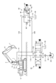
- FIG. 1 is a circuit diagram showing a hydraulic circuit to which a hydraulic valve according to an embodiment of the present invention is applied.
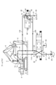
- FIG. 2 is a diagram showing a state in which the hydraulic cylinder in the circuit diagram shown in FIG. 1 is in an extending operation.
- FIG. 3 is a diagram showing a state in which the hydraulic cylinder is retracted in the circuit diagram shown in FIG. 1.
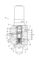
- FIG. 4 is a sectional view showing the structure of a hydraulic valve applied to the circuit diagram shown in FIG.
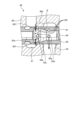
- FIG. 5 is an enlarged sectional view of a main part of the hydraulic valve shown in FIG. 4.
- FIG. 6 is a partially enlarged view of FIG. 5.
- the hydraulic circuit illustrated here is for operating the hydraulic cylinder 1 with oil supplied from a hydraulic pump.
- the hydraulic cylinder 1 is a single-rod double-acting type equipped with a single piston 2.
- a hydraulic cylinder 1 for operating a boom 3 in a working machine is illustrated.
- the working machine has an upper revolving body 5 disposed above a lower traveling body 4 so as to be rotatable around a vertical pivot axis, and the upper revolving body 5 is equipped with a boom 3.
- the boom 3 is rotatably supported by the upper revolving body 5 via its base end by a boom support shaft extending in the horizontal direction.
- Reference numeral 6 in the figure is an arm provided at the tip of the boom 3, and reference numeral 7 is a bucket provided at the tip of the arm 6.
- the hydraulic cylinder 1 is connected to the upper revolving body 5 via a cylinder body 8 and to the boom 3 via a rod 9.
- a bottom oil passage 11 is connected to a bottom chamber 1a
- a rod oil passage 12 is connected to a rod chamber 1b.
- the bottom oil passage 11 branches into a first bottom oil passage 11A and a second bottom oil passage (meter-out oil passage) 11B in the middle.
- the rod oil passage 12 is bifurcated into a first rod oil passage 12A and a second rod oil passage 12B.
- the hydraulic circuit includes a hydraulic pump 20, a direction switching valve 30 for operating the hydraulic cylinder 1, and a flow rate control valve (hydraulic valve) 40.
- the hydraulic pump 20 is of a variable displacement type driven by an engine (not shown).
- a pump oil passage 22 having a check valve 21 is connected to a discharge port of the hydraulic pump 20.
- the directional switching valve 30 is operated by pilot pressure from an operation valve (not shown), and is configured to switch the connection state of the pump port 33 and the tank port 34 with respect to the first input/output port 31 and the second input/output port 32. It has been done. To explain in more detail, when the directional switching valve 30 is placed in the neutral position shown in FIG. 1, the two input/output ports 31 and 32, the pump port 33, and the tank port 34 are respectively blocked. When moved from this state to the left and placed in the extended position as shown in FIG. It is now connected to the tank port 34. On the other hand, when the neutral position is moved to the right and placed in the retracted position as shown in FIG. It will be connected.
- a first bottom oil passage 11A is connected to a first input/output port 31, and a first rod oil passage 12A is connected to a second input/output port 32.
- a pump oil passage 22 is connected to the pump port 33, and a tank oil passage 51 leading to an oil tank 50 is connected to the tank port 34.
- the flow rate control valve 40 is operated by pilot pressure from an operation valve (not shown), and switches the connection state of the drain port (second port) 42 and regeneration port 43 to the meter out port (first port) 41. It is structured as follows. More specifically, when the flow control valve 40 is placed in the closed position shown in the figure, the meter out port 41, the drain port 42, and the regeneration port 43 are each cut off. When moved from this state to the left and placed at the control position as shown in the figure, the flow rate control valve 40 will be in a state where the meter out port 41 is connected to the drain port 42 and the regeneration port 43.
- a meter-out throttle 44 is provided between the meter-out port 41, the drain port 42, and the regeneration port 43 so that the opening area increases as the pilot pressure applied from the operating valve (not shown) increases.
- a drain-side fixed throttle 45 is provided between the meter-out port 41 and the drain port 42 downstream of the meter-out throttle 44.
- a check valve 46 and a regeneration-side fixed throttle 47 are provided downstream of the meter-out throttle 44 between the meter-out port 41 and the regeneration port 43 .
- a second bottom oil passage 11B is connected to a meter out port 41, and a tank oil passage 51 is connected to a drain port 42.
- the regeneration port 43 is connected to the second rod oil passage 12B.
- the flow control valve 40 includes a valve body 60 configured in a block shape.
- the valve body 60 is provided with a spool hole 61, and the above-mentioned meter out port 41, drain port 42, and regeneration port 43 are provided so as to communicate with the spool hole 61.
- the spool hole 61 is a through hole with a circular cross section and a straight axis, and includes a spool 62 therein.
- the spool 62 is a cylindrical member having an outer diameter that fits into the spool hole 61, and is disposed in the valve body 60 so as to be movable along the axis of the spool hole 61.
- a return spring between the end of the spool 62 and the valve body 60 that biases the spool 62 to the right side in FIG. 48 (see FIG. 1), and a pressure chamber 49 (see FIG. 1) to which pilot pressure is supplied from an operating valve (not shown).
- the pressure chamber 49 moves the spool 62 against the spring force of the return spring 48 when pilot pressure is supplied from an operation valve (not shown) to place the directional control valve 30 in the retracted position. It functions to move it to the left.
- the meter out port 41, the drain port 42, and the regeneration port 43 are configured to have a portion surrounding the spool hole 61, and are provided at positions separated from each other in the axial direction of the spool 62.
- a drain port 42 and a regeneration port 43 are provided on both sides of the meter out port 41.
- the spool 62 is provided with a main passage portion 63.
- the main passage section 63 is a through hole formed in the axial center of the spool 62, and includes a reference area 63a, a meter-out area (first area) 63b, a tapered area (third area) 63c, and a drain area (second area). 63d and a valve region 63e.
- the reference region 63a is a hollow space with a circular cross section, and is configured to have a constant inner diameter.
- the meter-out area 63b is a hollow space with a circular cross section and a constant inner diameter, and is provided adjacent to the right side of the reference area 63a in FIG.
- the meter-out area 63b has an inner diameter larger than the reference area 63a.
- a meter-out passage portion (first passage portion) 63f for forming the meter-out throttle 44 described above is formed in the meter-out region 63b.
- the meter-out passage section 63f is a through hole with a circular cross section formed along the radial direction of the spool 62, and a plurality of through holes having different cross sectional areas are formed in parallel in the circumferential direction and the axial direction. There is.
- meter-out passage portions 63f are completely covered by the land portion 60a located between the meter-out port 41 and the drain port 42 in the valve body 60 when the spool 62 is placed in the normal position. Become. On the other hand, when the spool 62 moves to the left with respect to the valve body 60, the meter-out passage section 63f opens to the meter-out port 41, and the opening area between the main passage section 63 and the meter-out port 41 It functions to gradually increase the In the flow control valve 40 of this embodiment, the inner diameter of the meter-out region 63b is formed larger than the reference region 63a, so that it is possible to form a large number of meter-out passages 63f without mutual interference. becomes.
- the tapered region 63c is a space provided adjacent to the right side of the meter-out region 63b, and is formed in a tapered shape whose inner diameter gradually decreases toward the right side.
- the inner diameter of the tapered region 63c decreases at a constant rate, and the inner circumferential surface extends linearly in a cross section including the axis.
- the tapered region 63c is formed such that the inclination angle ⁇ with respect to the meter-out region 63b is 21°.
- the inclination angle ⁇ of the tapered region 63c is preferably in the range of 15 to 30 degrees.
- the rate at which the inner diameter decreases toward the right side along the axial direction is in the range of tan 15° to tan 30°.
- the inner diameter of the rightmost portion of the tapered region 63c is set to be larger than the reference region 63a and smaller than the meter-out region 63b.
- the drain region 63d is a hollow space with a circular cross section and a constant inner diameter provided adjacent to the right side of the tapered region 63c.
- the inner diameter of the drain region 63d is the same as the narrowest diameter portion of the tapered region 63c.
- This drain region 63d is provided with a drain passage portion (second passage portion) 63g for forming the above-mentioned drain side fixed throttle 45.
- the drain passage portions 63g are through holes formed along the radial direction of the spool 62 and have a circular cross section, and are formed in plurality so as to be equally spaced from each other along the circumferential direction.
- drain passage portions 63g are always connected to the drain port 42 from the state in which the spool 62 is placed in the normal position to the state in which the spool 62 moves to the left and all meter-out passage portions 63f open to the meter-out port 41. It is set up so that it communicates with the.
- a plug 64 is attached to a portion of the main passage portion 63 on the right side of the drain region 63d.
- the valve region 63e is a hollow space with a circular cross section provided adjacent to the left side of the reference region 63a.
- This valve region 63e accommodates a valve body 65 and a return spring 66 for forming the above-mentioned check valve 46, and is also provided with a regeneration passage portion 63h for forming the above-mentioned regeneration-side fixed throttle 47. be.
- the valve body 65 blocks the flow of oil between the reference region 63a and the valve seat portion 63i when it comes into contact with the valve seat portion 63i provided between the reference region 63a and the valve region 63e. Allow oil to flow between them when separated.
- the return spring 66 is interposed between the valve body 65 and a plug 67 attached to the left side of the valve region 63e in the main passage section 63, and is attached so that the valve body 65 is always in contact with the valve seat section 63i. It is something that strengthens.
- the regeneration passage portion 63h is a through hole formed along the radial direction of the spool 62 and has a circular cross section, and a plurality of regeneration passage portions 63h are formed at equal intervals from each other along the circumferential direction.
- the tapered region 63c is provided in which the inner diameter gradually decreases from the meter-out region 63b to the drain region 63d, the oil flows smoothly downstream. . Therefore, the air bubbles generated in the oil when it flows into the main passage section 63 from the meter out port 41 do not remain in the meter out area 63b but proceed downstream and are discharged to the drain port 42 through the drain passage section 63g. will be done. Furthermore, when the oil reverses from the drain area 63d toward the meter-out area 63b, the tapered area 63c functions as a diffuser, and the pressure of the oil decreases when it reaches the meter-out area 63b.
- a hydraulic cylinder for operating a boom of a working machine is exemplified, but the present invention is not limited thereto.
- the first port does not need to be a meter-out port
- the second port does not need to be a drain port.
- a tapered portion in which the inner diameter decreases at a constant rate is illustrated as the third region, the rate at which the inner diameter decreases from the first region to the second region changes and may be curved in a convex shape. It is also possible to configure the tapered portion to be curved concavely.
Landscapes
- Engineering & Computer Science (AREA)
- General Engineering & Computer Science (AREA)
- Mechanical Engineering (AREA)
- Structural Engineering (AREA)
- Mining & Mineral Resources (AREA)
- Civil Engineering (AREA)
- Fluid Mechanics (AREA)
- Physics & Mathematics (AREA)
- Chemical & Material Sciences (AREA)
- Analytical Chemistry (AREA)
- Fluid-Pressure Circuits (AREA)
- Sliding Valves (AREA)
- Multiple-Way Valves (AREA)
Abstract
Description
1a ボトム室
11B 第2ボトム油路
40 流量制御バルブ
41 メータアウトポート
42 ドレンポート
50 油タンク
51 タンク油路
60 バルブ本体
62 スプール
63 主通路部
63b メータアウト領域
63c テーパ領域
63d ドレン領域
63f メータアウト通路部
63g ドレン通路部
Claims (4)
- 互いに独立した第1ポート及び第2ポートを有するバルブ本体と、
前記バルブ本体に対して軸心に沿って移動可能に配設されたスプールとを備え、
前記スプールには、軸心部分に設けられた主通路部と、前記主通路部から外周面までの間に設けられ、前記第1ポートに連通可能となる第1通路部と、前記主通路部から外周面までの間に設けられ、前記第2ポートに連通可能となる第2通路部とが設けられ、
前記スプールの移動に伴って前記第1ポートに対する前記第1通路部の開口面積を変化させることにより前記第1ポートから前記主通路部を経由して前記第2ポートに至る油の流量制御を行う油圧バルブであって、
前記第1通路部は、前記第1ポートに連通するタイミングが互いに異なるように前記スプールに複数設けられ、
前記スプールの主通路部は、前記第1通路部が設けられる第1領域と、前記第2通路部が設けられる第2領域と、これら前記第1領域及び前記第2領域の間を連続させる第3領域とを有し、前記第1領域の内径が前記第2領域よりも大きく形成され、前記第3領域が前記第2領域に向けて内径が漸次減少するテーパ状に構成されていることを特徴とする油圧バルブ。 - 前記第3領域は、前記第1領域から前記第2領域に向けて一定の割合で内径が減少していることを特徴とする請求項1に記載の油圧バルブ。
- 前記第3領域は、前記主通路部の軸心方向の長さに対して内径が減少する割合がtan15°~tan30°の範囲にあることを特徴とする請求項2に記載の油圧バルブ。
- 請求項1~請求項3のいずれか一つに記載した油圧バルブの前記第1ポートに油圧シリンダのボトム室との間を連通するメータアウト油路が接続され、前記第2ポートに油タンクとの間を連通するタンク油路が接続されていることを特徴とする油圧回路。
Priority Applications (2)
| Application Number | Priority Date | Filing Date | Title |
|---|---|---|---|
| CN202380030658.4A CN118946752A (zh) | 2022-05-13 | 2023-04-04 | 液压阀及液压回路 |
| DE112023000979.1T DE112023000979B4 (de) | 2022-05-13 | 2023-04-04 | Hydraulikventil und hydraulikkreislauf |
Applications Claiming Priority (2)
| Application Number | Priority Date | Filing Date | Title |
|---|---|---|---|
| JP2022-079739 | 2022-05-13 | ||
| JP2022079739A JP2023168091A (ja) | 2022-05-13 | 2022-05-13 | 油圧バルブ及び油圧回路 |
Publications (1)
| Publication Number | Publication Date |
|---|---|
| WO2023218803A1 true WO2023218803A1 (ja) | 2023-11-16 |
Family
ID=88730000
Family Applications (1)
| Application Number | Title | Priority Date | Filing Date |
|---|---|---|---|
| PCT/JP2023/013978 Ceased WO2023218803A1 (ja) | 2022-05-13 | 2023-04-04 | 油圧バルブ及び油圧回路 |
Country Status (4)
| Country | Link |
|---|---|
| JP (1) | JP2023168091A (ja) |
| CN (1) | CN118946752A (ja) |
| DE (1) | DE112023000979B4 (ja) |
| WO (1) | WO2023218803A1 (ja) |
Citations (2)
| Publication number | Priority date | Publication date | Assignee | Title |
|---|---|---|---|---|
| JPH09159036A (ja) * | 1995-12-08 | 1997-06-17 | Hitachi Constr Mach Co Ltd | 方向制御弁 |
| JP2002181004A (ja) * | 2000-12-11 | 2002-06-26 | Yanmar Diesel Engine Co Ltd | 掘削旋回作業車のブームシリンダ用切換弁 |
Family Cites Families (3)
| Publication number | Priority date | Publication date | Assignee | Title |
|---|---|---|---|---|
| ZA771041B (en) * | 1976-05-06 | 1977-12-28 | Commercial Shearing | Control valves |
| JP2007107677A (ja) | 2005-10-17 | 2007-04-26 | Komatsu Ltd | 流量制御弁 |
| CN104455548B (zh) | 2014-12-15 | 2016-09-28 | 山东华伟液压科技有限公司 | 一种油液再生阀及其工作方法 |
-
2022
- 2022-05-13 JP JP2022079739A patent/JP2023168091A/ja active Pending
-
2023
- 2023-04-04 CN CN202380030658.4A patent/CN118946752A/zh active Pending
- 2023-04-04 WO PCT/JP2023/013978 patent/WO2023218803A1/ja not_active Ceased
- 2023-04-04 DE DE112023000979.1T patent/DE112023000979B4/de active Active
Patent Citations (2)
| Publication number | Priority date | Publication date | Assignee | Title |
|---|---|---|---|---|
| JPH09159036A (ja) * | 1995-12-08 | 1997-06-17 | Hitachi Constr Mach Co Ltd | 方向制御弁 |
| JP2002181004A (ja) * | 2000-12-11 | 2002-06-26 | Yanmar Diesel Engine Co Ltd | 掘削旋回作業車のブームシリンダ用切換弁 |
Also Published As
| Publication number | Publication date |
|---|---|
| DE112023000979T5 (de) | 2024-12-19 |
| JP2023168091A (ja) | 2023-11-24 |
| CN118946752A (zh) | 2024-11-12 |
| DE112023000979B4 (de) | 2026-04-16 |
Similar Documents
| Publication | Publication Date | Title |
|---|---|---|
| KR102678535B1 (ko) | 방향 전환 밸브 및 유압 시스템 | |
| JP6600386B1 (ja) | 弁装置 | |
| CN116529441B (zh) | 多控制阀 | |
| KR102652880B1 (ko) | 유량 제어 밸브 | |
| KR101831494B1 (ko) | 방향 전환 밸브 | |
| US10107309B2 (en) | Load sensing valve device | |
| WO2023218803A1 (ja) | 油圧バルブ及び油圧回路 | |
| KR0146708B1 (ko) | 압력보상 유압밸브 | |
| WO2023218802A1 (ja) | 油圧バルブ及び油圧回路 | |
| JP2020094642A (ja) | 建設機械の油圧制御回路 | |
| JP2019056464A (ja) | 流量制御弁 | |
| JP7423189B2 (ja) | 制御弁及び建設機械用油圧システム | |
| JP7723588B2 (ja) | 弁装置 | |
| JP7601970B1 (ja) | 制御弁 | |
| JP7798647B2 (ja) | 方向制御弁 | |
| JP6898834B2 (ja) | 流体圧制御装置 | |
| JP7316423B2 (ja) | 流量制御弁 | |
| JP7805484B2 (ja) | 流体圧制御装置 | |
| WO2023189986A1 (ja) | 流量制御弁 | |
| JP7397561B2 (ja) | 弁装置 | |
| WO2021172098A1 (ja) | 流体圧駆動ユニット | |
| JP2021110360A (ja) | 油圧回路、油圧回路用の方向切換弁および建設機械 |
Legal Events
| Date | Code | Title | Description |
|---|---|---|---|
| 121 | Ep: the epo has been informed by wipo that ep was designated in this application |
Ref document number: 23803286 Country of ref document: EP Kind code of ref document: A1 |
|
| WWE | Wipo information: entry into national phase |
Ref document number: 18850086 Country of ref document: US |
|
| WWE | Wipo information: entry into national phase |
Ref document number: 202380030658.4 Country of ref document: CN |
|
| WWE | Wipo information: entry into national phase |
Ref document number: 112023000979 Country of ref document: DE |
|
| 122 | Ep: pct application non-entry in european phase |
Ref document number: 23803286 Country of ref document: EP Kind code of ref document: A1 |