WO2023218771A1 - 発電システムおよび制御方法 - Google Patents
発電システムおよび制御方法 Download PDFInfo
- Publication number
- WO2023218771A1 WO2023218771A1 PCT/JP2023/011931 JP2023011931W WO2023218771A1 WO 2023218771 A1 WO2023218771 A1 WO 2023218771A1 JP 2023011931 W JP2023011931 W JP 2023011931W WO 2023218771 A1 WO2023218771 A1 WO 2023218771A1
- Authority
- WO
- WIPO (PCT)
- Prior art keywords
- power
- discharge
- storage battery
- abnormality
- power generation
- Prior art date
- Legal status (The legal status is an assumption and is not a legal conclusion. Google has not performed a legal analysis and makes no representation as to the accuracy of the status listed.)
- Ceased
Links
Images






Classifications
-
- F—MECHANICAL ENGINEERING; LIGHTING; HEATING; WEAPONS; BLASTING
- F01—MACHINES OR ENGINES IN GENERAL; ENGINE PLANTS IN GENERAL; STEAM ENGINES
- F01D—NON-POSITIVE DISPLACEMENT MACHINES OR ENGINES, e.g. STEAM TURBINES
- F01D15/00—Adaptations of machines or engines for special use; Combinations of engines with devices driven thereby
- F01D15/10—Adaptations for driving, or combinations with, electric generators
-
- F—MECHANICAL ENGINEERING; LIGHTING; HEATING; WEAPONS; BLASTING
- F02—COMBUSTION ENGINES; HOT-GAS OR COMBUSTION-PRODUCT ENGINE PLANTS
- F02C—GAS-TURBINE PLANTS; AIR INTAKES FOR JET-PROPULSION PLANTS; CONTROLLING FUEL SUPPLY IN AIR-BREATHING JET-PROPULSION PLANTS
- F02C7/00—Features, components parts, details or accessories, not provided for in, or of interest apart form groups F02C1/00 - F02C6/00; Air intakes for jet-propulsion plants
- F02C7/26—Starting; Ignition
-
- F—MECHANICAL ENGINEERING; LIGHTING; HEATING; WEAPONS; BLASTING
- F02—COMBUSTION ENGINES; HOT-GAS OR COMBUSTION-PRODUCT ENGINE PLANTS
- F02C—GAS-TURBINE PLANTS; AIR INTAKES FOR JET-PROPULSION PLANTS; CONTROLLING FUEL SUPPLY IN AIR-BREATHING JET-PROPULSION PLANTS
- F02C7/00—Features, components parts, details or accessories, not provided for in, or of interest apart form groups F02C1/00 - F02C6/00; Air intakes for jet-propulsion plants
- F02C7/26—Starting; Ignition
- F02C7/268—Starting drives for the rotor, acting directly on the rotor of the gas turbine to be started
-
- F—MECHANICAL ENGINEERING; LIGHTING; HEATING; WEAPONS; BLASTING
- F02—COMBUSTION ENGINES; HOT-GAS OR COMBUSTION-PRODUCT ENGINE PLANTS
- F02C—GAS-TURBINE PLANTS; AIR INTAKES FOR JET-PROPULSION PLANTS; CONTROLLING FUEL SUPPLY IN AIR-BREATHING JET-PROPULSION PLANTS
- F02C7/00—Features, components parts, details or accessories, not provided for in, or of interest apart form groups F02C1/00 - F02C6/00; Air intakes for jet-propulsion plants
- F02C7/26—Starting; Ignition
- F02C7/268—Starting drives for the rotor, acting directly on the rotor of the gas turbine to be started
- F02C7/275—Mechanical drives
-
- F—MECHANICAL ENGINEERING; LIGHTING; HEATING; WEAPONS; BLASTING
- F02—COMBUSTION ENGINES; HOT-GAS OR COMBUSTION-PRODUCT ENGINE PLANTS
- F02C—GAS-TURBINE PLANTS; AIR INTAKES FOR JET-PROPULSION PLANTS; CONTROLLING FUEL SUPPLY IN AIR-BREATHING JET-PROPULSION PLANTS
- F02C7/00—Features, components parts, details or accessories, not provided for in, or of interest apart form groups F02C1/00 - F02C6/00; Air intakes for jet-propulsion plants
- F02C7/32—Arrangement, mounting, or driving, of auxiliaries
-
- G—PHYSICS
- G01—MEASURING; TESTING
- G01R—MEASURING ELECTRIC VARIABLES; MEASURING MAGNETIC VARIABLES
- G01R31/00—Arrangements for testing electric properties; Arrangements for locating electric faults; Arrangements for electrical testing characterised by what is being tested not provided for elsewhere
- G01R31/36—Arrangements for testing, measuring or monitoring the electrical condition of accumulators or electric batteries, e.g. capacity or state of charge [SoC]
- G01R31/3644—Constructional arrangements
- G01R31/3647—Constructional arrangements for determining the ability of a battery to perform a critical function, e.g. cranking
-
- G—PHYSICS
- G01—MEASURING; TESTING
- G01R—MEASURING ELECTRIC VARIABLES; MEASURING MAGNETIC VARIABLES
- G01R31/00—Arrangements for testing electric properties; Arrangements for locating electric faults; Arrangements for electrical testing characterised by what is being tested not provided for elsewhere
- G01R31/36—Arrangements for testing, measuring or monitoring the electrical condition of accumulators or electric batteries, e.g. capacity or state of charge [SoC]
- G01R31/385—Arrangements for measuring battery or accumulator variables
- G01R31/387—Determining ampere-hour charge capacity or SoC
-
- H—ELECTRICITY
- H02—GENERATION; CONVERSION OR DISTRIBUTION OF ELECTRIC POWER
- H02P—CONTROL OR REGULATION OF ELECTRIC MOTORS, ELECTRIC GENERATORS OR DYNAMO-ELECTRIC CONVERTERS; CONTROLLING TRANSFORMERS, REACTORS OR CHOKE COILS
- H02P9/00—Arrangements for controlling electric generators for the purpose of obtaining a desired output
- H02P9/04—Control effected upon non-electric prime mover and dependent upon electric output value of the generator
Definitions
- the present disclosure relates to a power generation system and a control method.
- This application claims priority based on Japanese Patent Application No. 2022-076850 filed in Japan on May 9, 2022, the contents of which are incorporated herein.
- Patent Document 1 describes a rotating machine (gas turbine power generator) that uses a DC motor as a starting device and uses a storage battery as a power source.
- the rotating machine described in Patent Document 1 has a problem in that, for example, if the storage battery becomes abnormal, the rotating machine may not be able to start.
- the present disclosure has been made to solve the above problems, and provides a power generation system and control method that can appropriately respond to abnormalities in a storage battery for supplying power to a starter device of a rotating machine. With the goal.
- a power generation system includes a rotating machine, a plurality of storage batteries, a discharge control section that controls discharge of the plurality of storage batteries, and an abnormality detection section that detects an abnormality of the storage batteries.
- the discharge control unit is configured to cause the abnormality detection unit to detect the abnormality when the plurality of storage batteries supply electric power used for starting the rotating machine by discharging from the plurality of storage batteries.
- a control method is a method for controlling a power generation system that includes a rotating machine, a plurality of storage batteries, a discharge control section that controls discharge of the plurality of storage batteries, and an abnormality detection section that detects an abnormality in the storage batteries.
- the discharge control unit may cause the abnormality detection unit to detect an abnormality in the storage battery when the plurality of storage batteries are supplying power used for starting the rotating machine by discharging from the plurality of storage batteries. In this case, after the discharge from the storage battery in which the abnormality has been detected is supplied from the grid, the discharge from the storage battery in which the abnormality has been detected is supplied to the other storage batteries in which no abnormality has been detected. Increase discharge power.
- FIG. 1 is a configuration diagram showing a configuration example of a power generation system according to an embodiment of the present disclosure.
- 1 is a schematic diagram showing an example of the operation of a power generation system according to an embodiment of the present disclosure.
- FIG. 2 is a schematic diagram illustrating an example of a startup process of a gas turbine according to an embodiment of the present disclosure.
- FIG. 2 is a schematic diagram for explaining an example of the operation of the power generation system according to the embodiment of the present disclosure.
- 3 is a flowchart illustrating an example of the operation of the power generation system according to the embodiment of the present disclosure.
- 3 is a flowchart illustrating an example of the operation of the power generation system according to the embodiment of the present disclosure.
- FIG. 2 is a schematic diagram for explaining an example of the operation of the power generation system according to the embodiment of the present disclosure.
- FIG. 2 is a schematic diagram for explaining an example of the operation of the power generation system according to the embodiment of the present disclosure.
- FIG. 2 is a schematic diagram for explaining an example of the operation of the power generation system according to the embodiment of the present disclosure.
- 3 is a flowchart illustrating an example of the operation of the power generation system according to the embodiment of the present disclosure.
- 3 is a flowchart illustrating an example of the operation of the power generation system according to the embodiment of the present disclosure.
- FIG. 2 is a schematic diagram for explaining an example of the operation of the power generation system according to the embodiment of the present disclosure.
- FIG. 2 is a schematic diagram for explaining an example of the operation of the power generation system according to the embodiment of the present disclosure.
- FIG. 2 is a schematic diagram for explaining an example of the operation of the power generation system according to the embodiment of the present disclosure.
- FIG. 2 is a schematic diagram for explaining an example of the operation of the power generation system according to the embodiment of the present disclosure.
- FIG. 2 is a schematic diagram for explaining an example of the operation of the power generation system according to the embodiment of the present disclosure.
- FIG. 2 is a schematic diagram for explaining an example of the operation of the power generation system according to the embodiment of the present disclosure.
- FIG. 1 is a schematic block diagram showing the configuration of a computer according to at least one embodiment.
- FIG. 1 is a configuration diagram showing a configuration example of a power generation system according to an embodiment of the present disclosure.
- FIG. 2 is a schematic diagram showing an example of the operation of the power generation system according to the embodiment of the present disclosure.
- FIG. 3 is a schematic diagram illustrating an example of a startup process of a gas turbine according to an embodiment of the present disclosure.
- FIG. 4 is a schematic diagram for explaining an example of the operation of the power generation system according to the embodiment of the present disclosure.
- 5 and 6 are flowcharts illustrating an example of the operation of the power generation system according to the embodiment of the present disclosure.
- FIGS. 7 to 9 are schematic diagrams for explaining operation examples of the power generation system according to the embodiment of the present disclosure.
- 10 and 11 are flowcharts illustrating an example of the operation of the power generation system according to the embodiment of the present disclosure.
- 12 to 17 are schematic diagrams for explaining operation examples of the power generation system according to the embodiment of the present disclosure.
- the same reference numerals are used for the same or corresponding components, and the description thereof will be omitted as appropriate.
- a power generation system 1 includes a power generation facility 2 and a power storage facility 3.
- the power input/output line 11 of the power generation facility 2 is connected to the power transmission/distribution line 6 via a wattmeter 73.
- a power input/output line 12 of the power storage facility 3 is connected to a power transmission/distribution line 6 .
- the power input/output line 13 of the production facility 4 is connected to the power transmission/distribution line 6 .
- the power transmission and distribution line 6 is connected to the system 5 via a transformer 72 and a power meter 71.
- the system 5 is also referred to as an electric power system.
- the power input from the grid 5 to the power transmission/distribution line 6 is referred to as received power.
- the power output from the power generation equipment 2 to the power transmission and distribution line 6 is referred to as generated power.
- the power input to the power generation equipment 2 from the power transmission/distribution line 6 is referred to as power generation equipment consumption.
- the power output from the power storage equipment 3 to the power transmission and distribution line 6 is referred to as discharge power.
- the power input to the power storage facility 3 from the power transmission/distribution line 6 is referred to as charging power.
- the power input to the production equipment 4 from the power transmission/distribution line 6 is referred to as production equipment power consumption.
- the production equipment 4 is, for example, equipment in a factory, and consumes power supplied from the power transmission and distribution line 6 as a load.
- the system 5 is a system that performs power generation, power transformation, power transmission, and power distribution.
- a portion of the system 5 that transmits and distributes power is a grid 5a.
- the power transmission and distribution lines 6 are also a grid.
- the power storage equipment 3 is charged from the grid.
- FIG. 2 shows an example of daily changes in the received power supplied to the power generation system 1 and production equipment 4 shown in FIG. 1.
- the horizontal axis is time, and the vertical axis is received power.
- the power generation facility 2 stops generating power at night and generates power only during the day. Until the power generation equipment 2 starts generating electricity, power including the starting power of the power generation equipment 2 is received from the grid 5.
- the power generation equipment 2 completes startup and starts generating electricity, power is supplied from the power generation equipment 2 to the production equipment 4, and the received power becomes zero.
- the power generation facility 2 includes a gas turbine combined cycle (GTCC) power generation system 20 (hereinafter referred to as the GTCC power generation system 20).
- GTCC gas turbine combined cycle
- the power generated by the power generation equipment 2 is consumed as production equipment power consumption or charging power, or reversely flows to the grid 5, for example.
- the GTCC power generation system 20 includes a gas turbine 21, a generator 22, a steam turbine 23, an exhaust heat recovery boiler 24, a condenser 25, an excitation thyristor rectifier 26, and a GTCC control device 27 (not shown). Equipped with auxiliary equipment, etc.
- the generator 22 and the excitation thyristor rectifier 26 constitute a starting device 28 .
- the starting device 28 drives the gas turbine 21 by using the generator 22 as a motor when starting the gas turbine 21 .
- auxiliary equipment includes, for example, pumps for distributing circulating water, water supply, lubricating oil, etc., cooling fans, equipment in the monitoring room, and the like.
- the gas turbine 21 is one aspect of a rotating machine, and includes an air compressor 211, a combustor 212, and a turbine 213.
- the gas turbine 21 mixes and burns air compressed by an air compressor 211 and natural gas as a fuel in a combustor 212, and applies the combustion gas as a fluid to a rotor blade in a turbine 213 to generate kinetic energy of the fluid. It is a prime mover that obtains rotational power by converting rotation into rotational motion.
- Gas turbine 21 drives generator 22 .
- the rotating machine may be, for example, a gas turbine starter, a compressor, a centrifugal refrigerator, a pump, or the like.
- the exhaust heat recovery boiler 24 recovers the exhaust heat of the gas turbine exhaust gas 241 discharged from the gas turbine 21 and generates steam. In addition, the exhaust heat recovery boiler 24 recovers exhaust heat from the gas turbine exhaust gas 241, and after performing denitrification processing, exhausts it as exhaust heat recovery boiler exhaust gas 242, and releases it into the atmosphere from a chimney, etc. (not shown). Discharge.
- the generator 22 is a synchronous electric machine and is configured coaxially with the gas turbine 21 and the steam turbine 23.
- the generator 22 operates as a synchronous generator that converts the power of the gas turbine 21 and the steam turbine 23 into electric power and outputs it to the power transmission and distribution line 6 . Furthermore, when the gas turbine 21 is started, the generator 22 receives electric power supplied from the power transmission and distribution line 6 and operates as a synchronous motor.
- the steam turbine 23 is a prime mover that applies steam generated by the exhaust heat recovery boiler 24 to rotary blades to obtain rotational power.
- the condenser 25 condenses the steam that has passed through the steam turbine 23.
- the water condensed in the condenser 25 is supplied to the exhaust heat recovery boiler 24 via a pump or the like.
- the GTCC control device 27 receives detection signals from various sensors (not shown), control signals from a higher-level control device (not shown), etc., and controls various actuators in the power generation facility 2. For example, when the gas turbine 21 is started, the GTCC control device 27 controls each part of the gas turbine 21, and also controls the rotation speed and output torque of the starting device 28. Further, the GTCC control device 27 generates a plurality of types of signal signals according to a predetermined event at the time of starting the gas turbine, and outputs them to the power storage equipment control device 34 described later in the power storage equipment 3 via the communication line 81. do.
- the predetermined events include, for example, starting the gas turbine, reaching the spin rotation speed, ignition, and the self-sustaining rotation speed.
- the start of startup of the gas turbine is an event in which the startup device 28 is started and application of rotational torque from the startup device 28 to the gas turbine 21 in the turning state is started.
- Reaching the spin rotation speed is an event that a predetermined rotation speed suitable for purging operation of the exhaust duct of the gas turbine 21 being operated in a spin operation has been reached.
- the spin operation is also called cranking, and is an operation in which the gas turbine 21 is driven only by the starter 28 without inputting fuel.
- the purge operation is a spin operation for removing unburned fuel remaining in the combustor 212, duct, etc. at the time of startup and prior to ignition. Ignition is an event in which fuel begins to burn due to an ignition action.
- the self-sustaining rotational speed is an event in which the gas turbine 21 reaches a rotational speed at which it can maintain self-sustaining operation without receiving rotational torque from the starting device 28 or higher. Note that the self-sustaining rotation speed means completion of startup.
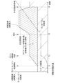
- FIG. 3 schematically shows changes in the power consumption of the power generation equipment and the gas turbine rotation speed when starting the gas turbine 21.
- the horizontal axis is time, and the vertical axis is power consumption of the power generation equipment and gas turbine rotation speed.
- the power consumption of the power generation equipment is shown by the solid line.
- the gas turbine rotation speed is indicated by a chain line.
- Power generation equipment power consumption includes gas turbine starting power (power covered by discharge power) and auxiliary equipment power consumption.
- the amount of gas turbine starting power (the area covered by the discharge power) is indicated by upward shading to the right.
- the power consumption of auxiliary equipment is indicated by downward shading.
- the gas turbine starting power is the power consumed by the starting device 28. In the example shown in FIG. 3, startup of the gas turbine is started at time t1.
- the rotational speed of the gas turbine 21 reaches a predetermined spin rotational speed. Thereafter, the rotational speed of the gas turbine 21 is controlled to be approximately constant, and a purge operation is performed. Then, ignition occurs at time t3. After ignition, the rotation speed of the gas turbine 21 increases and reaches the self-sustaining rotation speed at time t4. Further, the gas turbine starting power increases at a generally constant rate of increase from time t1 to time t2. Further, the gas turbine starting power is approximately constant from time t2 to time t3. Further, the gas turbine starting power increases from time t3, becomes constant at a certain value, and decreases from a certain time approaching time t4. Then, it becomes zero at time t4. Note that the change at startup shown in FIG. 3 is an example, and the application of this embodiment is not limited to this example.
- the power storage equipment 3 includes an AC/DC converter 31, three DC/DC converters 32, three storage battery packs 33, and a power storage equipment control device 34.
- the AC/DC converter 31 is a bidirectional AC-DC converter, and converts AC power input from the power transmission/distribution line 6 into DC power and outputs it to the DC/DC converter 32. It converts the DC power input from the converter 32 into AC power and outputs it to the power transmission and distribution line 6.
- the number of DC/DC converters 32 and storage battery packs 33 may be one each, or may be a plurality other than three.
- the DC/DC converter 32 is a bidirectional DC-DC converter, and boosts or steps down the voltage of the DC power input from the AC/DC converter 31 and outputs it to the storage battery pack 33 or converts it from the storage battery pack 33. It steps up or steps down the voltage of the input DC power and outputs it to the AC/DC converter 31. Further, for example, when discharging from the storage battery pack 33, the DC/DC converter 32 maintains the voltage of the DC power output to the AC/DC converter 31 at a constant value and controls the current according to instructions from the power storage equipment control device 34. By changing, the discharge power from the storage battery pack 33 is controlled. Each DC/DC converter 32 independently controls the discharge power from each storage battery pack 33 according to instructions from the power storage equipment control device 34.
- the storage battery pack 33 includes a circuit breaker 331, a storage battery 332, a sensor section 333, and a monitoring device 334.
- the storage battery 332 is configured by a combination of a plurality of storage battery cells (single batteries) or a storage battery module (battery assembly) made up of a plurality of storage battery cells.
- the storage battery cell is, for example (but not limited to) a lithium ion battery.
- the storage battery 332 is discharged, for example, when the gas turbine 21 is started.
- the circuit breaker 331 connects or disconnects the storage battery 332 and the DC/DC converter 32. The operation of the circuit breaker 331 is controlled by a monitoring device 334, for example.
- the sensor unit 333 includes a plurality of types of sensors, detects the voltage, current, temperature, etc. of the storage battery 332, and outputs the detected results to the monitoring device 334.
- the monitoring device 334 acquires the detection results of the sensor unit 333, controls the circuit breaker 331, and calculates the SOC (State Of Charge) of the storage battery 332. Further, the monitoring device 334 outputs information representing the acquired detection result of the sensor unit 333 and the calculated SOC to the power storage equipment control device 34. Further, the monitoring device 334 shuts off the circuit breaker 331 to protect the storage battery 332 when a predetermined event such as overvoltage, overcurrent, or overheating is detected based on the detection result of the sensor unit 333 .
- the monitoring device 334 outputs a signal indicating that the circuit breaker 331 has been shut off to the power storage equipment control device 34. Further, the monitoring device 334 shuts off or connects the circuit breaker 331 when receiving a predetermined instruction from the power storage equipment control device 34 .
- the power storage equipment control device 34 can be configured using, for example, a computer and its peripheral circuits and peripheral devices.
- the power storage equipment control device 34 has a functional configuration consisting of a combination of hardware such as a computer and software such as a program.
- a detection section 344 is provided.
- the discharge control unit 341 controls the discharge of one or more storage batteries 332.
- “controlling the discharge of the storage battery 332” means at least one of controlling the discharge power of the storage battery 332, and controlling the discharge power and the amount of discharge power of the storage battery 332.
- the discharge control unit 341 controls the discharge power in a predetermined pattern to discharge the storage battery 332, for example, if the remaining power amount of the storage battery 332 is sufficient. Further, when starting the gas turbine 21, for example, if the remaining power amount of the storage battery 332 is not sufficient, the discharge control unit 341 changes the pattern so that the discharged power amount does not exceed the remaining power amount, and the storage battery 332 is activated. Let it discharge.
- the discharge control unit 341 controls discharge from the storage battery 332, for example, in response to a predetermined event when the gas turbine 21 is started.
- the event includes at least one of the start of startup of the gas turbine 21, reaching the spin rotation speed, ignition, or the self-sustaining rotation speed, all of which are described above with reference to FIG.
- the discharge amount control unit 341 receives a signal representing an event from the GTCC control device 27 as a signal signal.
- the GTCC control device 27 is an example of a configuration of a control section of the gas turbine 21.
- the discharge control unit 341 is configured such that, when starting the gas turbine 21, the electric power necessary for starting the gas turbine 21 can be covered by the electric power from the grid 5 and the discharged electric power from the storage battery 332. Controls discharge from storage battery 332.
- the discharge control unit 341 when the discharge control unit 341 is supplying electric power used for starting the gas turbine 21 from the plurality of storage batteries 332 by discharging from the plurality of storage batteries 332, when the abnormality detection unit 344 detects an abnormality in the storage battery 332, After the grid 5a supplies the amount of discharge from the storage battery 332 in which an abnormality has been detected, the discharged power from other storage batteries 332 in which no abnormality has been detected is supplied to cover the amount of discharge from the storage battery 332 in which an abnormality has been detected. raise.
- the storage battery remaining power amount calculation unit 342 calculates the remaining power amount of the storage battery 332.
- the storage battery remaining power amount calculation unit 342 obtains the SOC calculated by the monitoring device 334, for example, and calculates the total remaining power amount of the three storage batteries 332.
- the storage battery remaining power amount calculation unit 342 calculates the remaining power amount by calculating charging power and discharging power based on the current and voltage detected by the monitoring device 334, and integrating them.
- the power difference calculation unit 343 calculates the power difference between the predicted value of received power from the system 5 at the time of starting the gas turbine 21 and the total power value available from the system 5.
- the power difference calculation unit 343 receives, for example, information representing a predicted value of received power from a device that manages the production equipment 4 via the communication line 81.
- FIG. 4 shows an example of calculating the power difference ⁇ MW.
- the horizontal axis is time, and the vertical axis is received power.
- the actual value of received power is shown by a solid line rectangle, and the predicted value is shown by a broken line rectangle.
- the gas turbine starting power among the predicted values is shown shaded. In the example shown in FIG.
- the value of the maximum contract power is set as the total available power value, which is the value obtained by subtracting the predicted value MW of the received power from the grid 5 at the time of starting the gas turbine 21 from the value of the maximum contract power. is the power difference ⁇ MW.
- the total usable power value is not limited to the maximum contracted power value, and may be, for example, an upper limit value set to achieve a predetermined purpose.
- the abnormality detection unit 344 detects an abnormality in the storage battery 332 based on information acquired from each monitoring device 334.
- An abnormality in the storage battery 332 may be, for example, that the monitoring device 334 has shut off the circuit breaker 331, or that the temperature of the storage battery 332 has exceeded a predetermined temperature.
- FIG. 5 shows the basic operation flow when starting up the gas turbine 21.
- the power storage equipment control device 34 determines the discharge mode of the storage battery 332 when starting the gas turbine 21 (step S1), and discharges the storage battery 332 in the determined discharge mode. control (step S2).
- the discharge mode represents a mode of discharge from the power storage equipment 3.
- the discharge modes include a mode in which no discharge is performed (discharge stop), a mode in which a relatively large amount of electric power of the storage battery 332 is used (large discharge mode), and a mode in which the electric power of the storage battery 332 is used moderately ( A medium discharge mode) and a mode in which the power of the storage battery 332 is used only at the peak portion (small discharge mode) are set, and discharge is performed using either of these modes or not.
- the process shown in FIG. 5 may be started, for example, in response to a predetermined input operation by the operator, or when a predetermined signal is received from the power generation equipment 2 or the production equipment 4, or at a preset time. It may be started when the
- FIG. 6 shows the flow of step S1 for determining the discharge mode shown in FIG.
- FIG. 7 shows an example of large discharge mode.
- FIG. 8 shows an example of medium discharge mode.
- FIG. 9 shows an example of the small discharge mode. 7 to 9 show examples of power consumption of the same power generation equipment as shown in FIG. 3. However, in Figures 7 to 9, the amount of gas turbine starting power indicated by the upward shading in FIG. It is shown separately.
- the large discharge mode shown in FIG. 7 the region covered by the gas turbine starting power and the discharge power coincide in all periods from the start of startup to the self-sustaining rotation speed.
- a region is set in which part of the period from ignition to the independent rotation speed is covered by the received power.
- a region is set in which the entire period from the start of the gas turbine to ignition and a part of the period from ignition to the independent rotation speed are covered by the received power.
- the power storage equipment 3 stores enough power to at least cover the amount of discharged power in the small discharge mode (for example, enough to perform multiple startups). It is assumed that there is
- the power difference calculation unit 343 acquires the predicted received power value MW [W] (step S10), and calculates the power difference ⁇ MW (step S11).
- the storage battery remaining power amount calculation unit 342 calculates the remaining power amount BR [Wh] of the storage battery 332 (step S12).
- the discharge control unit 341 determines whether the power difference ⁇ MW [W] is larger than "0" (step S13). If the power difference ⁇ MW[W] is larger than "0" (step S13: YES), the discharge control unit 341 determines the discharge mode to be "discharge stop” (step S14), and ends the process shown in FIG. 6. . If the power difference ⁇ MW [W] is not larger than "0" (step S13: NO), the discharge control unit 341 determines whether the remaining power amount BR is larger than the discharge power amount [Wh] in the large discharge mode. (Step S15). Here, the amount of discharge power [Wh] in the large discharge mode corresponds to the area of the shaded portion upward to the right in FIG. 7 .
- step S15 If the remaining power amount BR is larger than the discharge power amount [Wh] in the large discharge mode (step S15: YES), the discharge control unit 341 determines the discharge mode to be the "large discharge mode" (step S16), The process shown in is ended. If the remaining power amount BR is not larger than the discharge power amount [Wh] in the large discharge mode (step S15: NO), the discharge control unit 341 determines whether the remaining power amount BR is larger than the discharge power amount [Wh] in the medium discharge mode. It is determined whether or not (step S17).
- the discharge power amount [Wh] in the medium discharge mode corresponds to the area of the shaded portion upward to the right in FIG. 8 .
- step S17: YES If the remaining power amount BR is larger than the discharge power amount [Wh] in the medium discharge mode (step S17: YES), the discharge control unit 341 determines the discharge mode to be the "medium discharge mode" (step S18), The process shown in is ended. If the remaining power amount BR is not larger than the discharge power amount [Wh] in the medium discharge mode (step S17: NO), the discharge control unit 341 determines the discharge mode to be the "small discharge mode” (step S19), and The process shown in 6 ends.
- step S13 instead of determining whether or not it is greater than "0", it may be determined whether or not it is greater than a certain margin " ⁇ " ( ⁇ >0).
- FIG. 10 shows the flow of step S2 for controlling the discharge shown in FIG.
- FIG. 11 shows the flow of the process executed in the process of controlling the discharge from the storage battery 332 (step S23, step S24, step S26, and step S28) in FIG.
- the discharge power from the power storage equipment 3 is controlled in accordance with the patterns shown in FIGS. 7 to 9, triggered by the reception of a predetermined signal signal.
- discharge from the power storage equipment 3 is started after a gas turbine activation start signal is received at time t1.
- the discharge power is increased at a predetermined rate of increase according to the elapsed time from time t1.
- the discharge power is controlled to a predetermined constant value.
- the discharge power is gradually increased at a predetermined rate of increase according to the elapsed time from time t3.
- the discharge power is controlled to a predetermined constant value. Thereafter, for example, when the elapsed time from time t3 reaches a predetermined value, the discharge power is reduced at a predetermined rate of decline. Thereafter, when the independent rotation speed signal is received at time t4, discharging from the power storage equipment 3 is stopped.
- the control of the discharge power is not limited to this, and the discharge power may be increased or decreased depending on the rotation speed of the gas turbine 21, for example.
- the discharge control unit 341 determines whether the discharge mode is discharge stop (step S20). When the discharge mode is discharge stop (step S20: YES), the discharge control unit 341 ends the process shown in FIG. 10 without discharging from the power storage equipment 3. If the discharge mode is not discharge stop (step S20: NO), the discharge control unit 341 waits for reception of a gas turbine activation start signal (step S21: repeats NO). When the gas turbine activation start signal is received (step S21: YES), the discharge control unit 341 determines whether the discharge mode is the large discharge mode or the medium discharge mode (step S22).
- step S22 When the discharge mode is the large discharge mode or the medium discharge mode (step S22: YES), the discharge control unit 341 starts discharging from the storage battery 332 (step S23). Next, the discharge control unit 341 increases the discharge power at a predetermined rate of increase according to the elapsed time since receiving the gas turbine activation start signal (step S24). Next, the discharge control unit 341 determines whether or not a spin rotation speed reaching signal has been received (step S25). If the spin rotation speed attainment signal has not been received (step S25: NO), the discharge control unit 341 again increases the discharge power at a predetermined increase rate according to the elapsed time since receiving the gas turbine startup start signal. increase (step S24). Note that the process in step S24 and the process in step S25 are executed at a constant cycle (that is, with a constant waiting time set between repeated processes).
- step S26 the discharge control unit 341 controls the discharge power at a constant predetermined value (step S26).
- step S27 the discharge control unit 341 determines whether an ignition signal has been received (step S27). If the ignition signal has not been received (step S27: NO), the discharge control unit 341 continues to control the discharge power at a constant predetermined value (step S26). Note that the processing in step S26 and the processing in step S27 are executed at regular intervals.
- step S22 if the discharge mode is not the large discharge mode or the medium discharge mode (step S22: NO), the discharge control unit 341 waits for reception of an ignition signal (step S31: repeats NO).
- step S27 If the ignition signal is received in step S27 or step S31 (step S27: YES or step S31: YES), the discharge control unit 341 controls the discharge power in a predetermined pattern according to the discharge mode (step S28).
- step S29 determines whether or not the independent rotation speed signal has been received.
- step S28 NO
- step S28 the processing in step S28 and the processing in step S29 are executed at regular intervals.
- step S29 If the independent rotation speed signal has been received (step S29: YES), the discharge control unit 341 stops discharging from the storage battery 332 (step S30), and ends the process shown in FIG. 10.
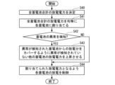
- step S40 the discharge control unit 341 first determines the total discharge power of all storage batteries (step S40).
- the total discharge power of all storage batteries is determined only once with power suitable for the start of discharge.
- the total discharge power of all storage batteries is determined such that, for example, the electric power increases at a predetermined rate of increase each time the process is executed.
- the total discharge power of all storage batteries is always determined to be a constant predetermined value.
- the total discharge power of all storage batteries is determined according to the patterns shown in FIGS. 7 to 9 each time the process is executed.
- the discharge control unit 341 equally allocates the total discharge power of all storage batteries to each storage battery 332 (step S41). For example, if the total discharge power of all storage batteries is P, in this embodiment, power of P/3 is equally allocated to the three storage batteries 332.
- the discharge control unit 341 determines whether the abnormality detection unit 344 has detected an abnormality in the storage battery 332 (step S42). On the other hand, if no abnormality is detected (step S42: NO), the discharge control unit 341 controls the discharge of each storage battery 332 so that the allocated discharge power is achieved (step S44), and ends the process shown in FIG. do.
- step S42 if an abnormality is detected (step S42: YES), the discharge control unit 341 controls the discharge power of other storage batteries 332 in which no abnormality has been detected so as to cover the amount of discharge from the storage battery 332 in which an abnormality has been detected. It is raised (step S43). For example, when an abnormality in one storage battery 332 is detected, the discharge control unit 341 sets the discharge power allocated to the storage battery 332 to "0" and increases the amount of discharge power allocated to the other storage batteries 332 to P/2. Next, the discharge control unit 341 controls the discharge of each storage battery 332 to reach the allocated discharge power (step S44), and ends the process shown in FIG. 11.
- each process of step S24, step S26, and step S28 is executed at a constant cycle. Therefore, for example, in the case of an abnormality in which the circuit breaker 331 is shut off by the monitoring device 334, a delay of about the same period may occur after the circuit breaker 331 is shut off until the discharge power of the other storage batteries 332 increases. become.
- the discharge control unit 341 detects that the abnormality detection unit 344 has detected an abnormality in the storage battery 332 when the plurality of storage batteries 332 are supplying electric power used for starting the gas turbine 21 by discharging from the plurality of storage batteries 332.
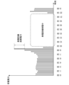
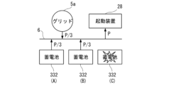
- FIGS. 12 to 14 show an example of the operation when the circuit breaker 331 is shut off in one of the three storage batteries 332 when the gas turbine 21 is started.
- the three storage batteries 332 are a storage battery 332 (A), a storage battery 332 (B), and a storage battery 332 (C).
- FIG. 12 shows that when the starting power P is evenly supplied by P/3 from the storage battery 332 (A), the storage battery 332 (B), and the storage battery 332 (C) when starting the gas turbine 21, the storage battery 332(C) shows a state where discharge has stopped.
- power of P/3 is supplied from the grid 5a before increasing the discharge power of the other storage batteries 332 (A) and 332 (B).
- the discharge power of the storage battery 332 (A) and the storage battery 332 (B) increases, as shown in FIG.
- the power supply to the starting device 28 continues.
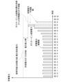
- FIGS. 15 to 17 show examples of temporal changes in the discharged power and amount of discharged power from the storage battery 332 (A), the storage battery 332 (B), and the storage battery 332 (C) when the gas turbine 21 is started.
- the solid line represents the discharge power from the power storage equipment 3.
- the broken line represents the amount of electric power discharged from the power storage equipment 3.
- the dashed lines represent the amount of electric power discharged from each storage battery 332 (A), storage battery 332 (B), and storage battery 332 (C).
- FIG. 15 shows a case where storage battery 332 (A), storage battery 332 (B), and storage battery 332 (C) are all normal.
- FIG. 16 shows a case where the storage battery 332 (C) stops discharging at time t11.
- FIG. 17 shows a case where the storage battery 332 (C) stops discharging immediately before starting. In this case, the storage battery 332 (A) and the storage battery 332 (B) are increasing the discharge power from the start of startup.
- the discharge control unit 341 detects an abnormality when the plurality of storage batteries 332 supplies electric power used for starting the gas turbine 21 by discharging from the plurality of storage batteries 332.
- the unit 344 detects an abnormality in the storage battery 332
- the discharge from the storage battery 332 in which the abnormality was detected is supplied from the grid 5a (or the power transmission/distribution line 6 as the grid), and then the discharge from the storage battery 332 in which the abnormality was detected is supplied.
- the discharge power of other storage batteries 332 in which no abnormality has been detected is increased to cover the discharge amount. Therefore, it is possible to appropriately respond to an abnormality in the storage battery 332 for supplying electric power to the starting device 28 of the gas turbine 21.
- the storage battery 332 is discharged during any period from the start of startup of the gas turbine 21 to the completion of startup of the gas turbine 21. According to this configuration, the capacity of the storage battery 332 can be appropriately set.
- the storage battery 332 is discharged during any period from ignition of the gas turbine 21 to completion of startup of the gas turbine 21. According to this configuration, the capacity of the storage battery 332 can be appropriately set.
- charging 332 of the storage battery is performed from the grid 5a (or the power transmission and distribution line 6 as the grid).
- the discharge control unit 341 equally controls each discharge power from the plurality of storage batteries 332. According to this configuration, the capacity of the storage battery 332 can be appropriately set.
- FIG. 18 is a schematic block diagram showing the configuration of a computer according to at least one embodiment.
- Computer 90 includes a processor 91, main memory 92, storage 93, and interface 94.
- the above-described power storage equipment control device 34 and GTCC control device 27 are implemented in a computer 90.
- the operations of each processing section described above are stored in the storage 93 in the form of a program.
- the processor 91 reads the program from the storage 93, expands it into the main memory 92, and executes the above processing according to the program. Further, the processor 91 reserves storage areas corresponding to each of the above-mentioned storage units in the main memory 92 according to the program.
- the program may be one for realizing a part of the functions to be performed by the computer 90.
- the program may function in combination with other programs already stored in storage or in combination with other programs installed in other devices.
- the computer may include a custom LSI (Large Scale Integrated Circuit) such as a PLD (Programmable Logic Device) in addition to or in place of the above configuration.
- PLDs include PAL (Programmable Array Logic), GAL (Generic Array Logic), CPLD (Complex Programmable Logic Device), FPGA (Field Programmable Gate Array), and the like.
- PLDs Programmable Logic Device
- PAL Programmable Array Logic
- GAL Generic Array Logic
- CPLD Complex Programmable Logic Device
- FPGA Field Programmable Gate Array
- Storage 93 examples include HDD (Hard Disk Drive), SSD (Solid State Drive), magnetic disk, magneto-optical disk, CD-ROM (Compact Disc Read Only Memory), and DVD-ROM (Digital Versatile Disc Read Only Memory). , semiconductor memory, etc.
- Storage 93 may be an internal medium connected directly to the bus of computer 90, or may be an external medium connected to computer 90 via an interface 94 or a communication line. Furthermore, when this program is distributed to the computer 90 via a communication line, the computer 90 that received the distribution may develop the program in the main memory 92 and execute the above processing.
- storage 93 is a non-transitory, tangible storage medium.
- the power generation system 1 includes a rotating machine (gas turbine 21), a plurality of storage batteries 332, a discharge control unit 341 that controls discharge of the plurality of storage batteries, and detects abnormality of the storage batteries.
- An abnormality detection unit 344 that performs a power generation system, in which the discharge control unit supplies power used for starting the rotating machine from the plurality of storage batteries by discharging from the plurality of storage batteries, When the abnormality detection unit detects an abnormality in the storage battery, the discharge from the storage battery in which the abnormality was detected is supplied from the grid (grid 5a, power transmission/distribution line 6), and then the storage battery in which the abnormality was detected is supplied.
- the discharge power of the other storage batteries in which no abnormality has been detected is increased to cover the discharge from the battery. According to this aspect and each of the following aspects, it is possible to appropriately respond to an abnormality in the storage battery 332 for supplying power to the starting device 28 of the rotating machine.
- a power generation system 1 according to a second aspect is the power generation system 1 according to (1), in which the storage battery is discharged during any period from the start of startup of the rotary machine to the completion of startup of the rotary machine. be done. According to this aspect, the capacity of the storage battery 332 for supplying electric power to the starting device 28 of the gas turbine 21 can be appropriately set.
- a power generation system 1 according to a third aspect is the power generation system 1 of (1) or (2), in which the rotating machine is a gas turbine.
- a power generation system 1 according to a fourth aspect is the power generation system 1 according to (3), wherein the storage battery is discharged during any period from ignition of the gas turbine to completion of startup of the gas turbine. Ru. According to this aspect, the capacity of the storage battery 332 for supplying electric power to the starting device 28 of the gas turbine 21 can be appropriately set.
- the power generation system 1 according to the fifth aspect is the power generation system 1 of (1) to (4), in which the storage battery is charged from the grid.
- the power generation system 1 according to the sixth aspect is the power generation system 1 of (1) to (5), in which the discharge control section equally controls each discharge power from the plurality of storage batteries. According to this aspect, the capacity of the storage battery 332 for supplying power to the starting device 28 of the rotating machine can be appropriately set.
- the power generation system and control method of the present disclosure it is possible to appropriately respond to an abnormality in a storage battery for supplying power to a starter device of a rotating machine.
Landscapes
- Engineering & Computer Science (AREA)
- Chemical & Material Sciences (AREA)
- Combustion & Propulsion (AREA)
- Mechanical Engineering (AREA)
- General Engineering & Computer Science (AREA)
- Physics & Mathematics (AREA)
- General Physics & Mathematics (AREA)
- Power Engineering (AREA)
- Supply And Distribution Of Alternating Current (AREA)
Abstract
Description
図1に示すように、本実施形態に係る発電システム1は、発電設備2と、蓄電設備3とを備える。発電設備2の電力の入出力線11は、電力量計73を介して、送配電線6に接続されている。蓄電設備3の電力の入出力線12は、送配電線6に接続されている。生産設備4の電力の入出力線13は、送配電線6に接続されている。送配電線6は、変圧器72および電力量計71を介して系統5に接続されている。系統5は、電力系統ともいう。なお、本実施形態では、系統5から送配電線6へ入力される電力を受電電力という。発電設備2から送配電線6へ出力される電力を発電電力という。発電設備2へ送配電線6から入力される電力を発電設備消費電力という。蓄電設備3から送配電線6へ出力される電力を放電電力という。蓄電設備3へ送配電線6から入力される電力を充電電力という。生産設備4へ送配電線6から入力される電力を生産設備消費電力という。生産設備4は、例えば工場内の設備であり、送配電線6から供給される電力を負荷として消費する。また、系統5は、発電、変電、送電および配電を行うシステムである。系統5のうち送電および配電を行う部分がグリッド5aである。また、送配電線6もグリッドである。蓄電設備3の充電は、グリッドから行なわれる。
発電設備2は、ガスタービンコンバインドサイクル(GTCC(Gas Turbine Combined Cycle))発電システム20(以下、GTCC発電システム20という)を備える。発電設備2が発電した電力は、例えば、生産設備消費電力や充電電力として消費されたり、系統5へ逆潮流されたりする。GTCC発電システム20は、ガスタービン21と、発電機22と、蒸気タービン23と、排熱回収ボイラ24と、復水器25と、励磁用サイリスタ整流器26と、GTCC制御装置27と、図示していない補機等を備える。発電機22と励磁用サイリスタ整流器26は、起動装置28を構成する。起動装置28は、ガスタービン21を起動する際に、発電機22をモータにしてガスタービン21を駆動する。なお、図示していない補機には、例えば、循環水、給水、潤滑油等を送り出すポンプ、冷却用のファン、監視室内の設備等がある。
なお、本実施形態においては、回転機械がガスタービン21である例で説明するが、他の実施形態ではこれに限定されない。他の実施形態において、回転機械は、例えば、ガスタービンの起動装置、圧縮機、ターボ冷凍機、ポンプなどであってよい。
蓄電設備3は、AC/DC変換器31と、3個のDC/DC変換器32と、3個の蓄電池パック33と、蓄電設備制御装置34とを備える。AC/DC変換器31は、双方向の交流-直流変換器であり、送配電線6から入力された交流電力を直流電力に変換してDC/DC変換器32へ出力したり、DC/DC変換器32から入力された直流電力を交流電力に変換して送配電線6へ出力したりする。なお、DC/DC変換器32と蓄電池パック33の個数は、各1個であってもよいし、3以外の複数であってもよい。
図5~図17を参照して、図1に示す発電システム1のガスタービン21の起動の際の動作例について説明する。図5は、ガスタービン21の起動の際の基本的な動作の流れを示す。図5に示すように、発電システム1では、蓄電設備制御装置34が、ガスタービン21の起動の際の蓄電池332の放電モードを決定し(ステップS1)、決定した放電モードで蓄電池332の放電を制御する(ステップS2)。本実施形態において、放電モードとは、蓄電設備3からの放電の態様を表す。本実施形態では、一例として、放電モードとして、放電を行わない態様(放電停止)と、蓄電池332の電力を比較的沢山使う態様(大放電モード)と、蓄電池332の電力を適度に使う態様(中放電モード)と、蓄電池332の電力をピーク部のみで使う態様(小放電モード)とを設定し、これらのいずれかを用いて放電を実行し、または実行しない。なお、図5に示す処理は、例えば、操作者の所定の入力操作に応じて開始されてもよいし、発電設備2や生産設備4から所定の信号を受信した場合や予め設定された時刻となった場合に開始されてもよい。
以上のように本実施形態の発電システム1は、放電制御部341が、複数の蓄電池332からの放電によってガスタービン21の起動に用いる電力を複数の蓄電池332から供給している場合に、異常検知部344が蓄電池332の異常を検知したとき、異常が検知された蓄電池332からの放電分をグリッド5a(あるいはグリッドとしての送配電線6)から供給した後、異常が検知された蓄電池332からの放電分をカバーするように異常が検知されていない他の蓄電池332の放電電力を上昇させる。したがって、ガスタービン21の起動装置28に電力を供給するための蓄電池332の異常に適切に対応することができる。
以上、本開示の実施の形態について図面を参照して詳述したが、具体的な構成はこの実施の形態に限られるものではなく、本開示の要旨を逸脱しない範囲の設計変更等も含まれる。
なお、上記実施形態では放電制御部341、蓄電池残電力量算出部342、電力差算出部343および異常検知部344を蓄電設備3内に設ける構成としたが、これに限るものではなく、例えばGTCC制御装置27内に設けてもよい。
図18は、少なくとも1つの実施形態に係るコンピュータの構成を示す概略ブロック図である。
コンピュータ90は、プロセッサ91、メインメモリ92、ストレージ93、および、インタフェース94を備える。
上述の蓄電設備制御装置34およびGTCC制御装置27は、コンピュータ90に実装される。そして、上述した各処理部の動作は、プログラムの形式でストレージ93に記憶されている。プロセッサ91は、プログラムをストレージ93から読み出してメインメモリ92に展開し、当該プログラムに従って上記処理を実行する。また、プロセッサ91は、プログラムに従って、上述した各記憶部に対応する記憶領域をメインメモリ92に確保する。
各実施形態に記載の発電システム1は、例えば以下のように把握される。
2…発電設備
3…蓄電設備
4…生産設備
5…系統
5a…グリッド
6…送配電線(グリッド)
20…GTCC発電システム
21…ガスタービン(回転機械)
22…発電機
27…GTCC制御装置(制御部)
28…起動装置
332…蓄電池
341…放電制御部
342…蓄電池残電力量算出部
343…電力差算出部
344…異常検知部
Claims (7)
- 回転機械と、
複数の蓄電池と、
前記複数の蓄電池の放電を制御する放電制御部と、
前記蓄電池の異常を検知する異常検知部と、
を備える発電システムであって、
前記放電制御部は、前記複数の蓄電池からの放電によって前記回転機械の起動に用いる電力を前記複数の蓄電池から供給している場合に、前記異常検知部が前記蓄電池の異常を検知したとき、前記異常が検知された前記蓄電池からの放電分をグリッドから供給した後、前記異常が検知された前記蓄電池からの放電分をカバーするように異常が検知されていない他の前記蓄電池の放電電力を上昇させる
発電システム。 - 前記蓄電池は、前記回転機械の起動開始から前記回転機械の起動完了までのいずれかの期間に放電される
請求項1に記載の発電システム。 - 前記回転機械は、ガスタービンである、
請求項1または請求項2に記載の発電システム。 - 前記蓄電池は、前記ガスタービンの着火から前記ガスタービンの起動完了までのいずれかの期間に放電される
請求項3に記載の発電システム。 - 前記蓄電池の充電は、前記グリッドから行なわれる
請求項4に記載の発電システム。 - 前記放電制御部は、前記複数の蓄電池からの各放電電力を等しく制御する
請求項5に記載の発電システム。 - 回転機械と、
複数の蓄電池と、
前記複数の蓄電池の放電を制御する放電制御部と、
前記蓄電池の異常を検知する異常検知部と、
を備える発電システムの制御方法であって、
前記放電制御部は、前記複数の蓄電池からの放電によって前記回転機械の起動に用いる電力を前記複数の蓄電池から供給している場合に、前記異常検知部が前記蓄電池の異常を検知したとき、前記異常が検知された前記蓄電池からの放電分をグリッドから供給した後、前記異常が検知された前記蓄電池からの放電分をカバーするように異常が検知されていない他の前記蓄電池の放電電力を上昇させる
制御方法。
Priority Applications (2)
| Application Number | Priority Date | Filing Date | Title |
|---|---|---|---|
| JP2024520282A JP7749116B2 (ja) | 2022-05-09 | 2023-03-24 | 発電システムおよび制御方法 |
| US18/861,959 US20250164560A1 (en) | 2022-05-09 | 2023-03-24 | Power generation system and control method |
Applications Claiming Priority (2)
| Application Number | Priority Date | Filing Date | Title |
|---|---|---|---|
| JP2022076850 | 2022-05-09 | ||
| JP2022-076850 | 2022-05-09 |
Publications (1)
| Publication Number | Publication Date |
|---|---|
| WO2023218771A1 true WO2023218771A1 (ja) | 2023-11-16 |
Family
ID=88730046
Family Applications (1)
| Application Number | Title | Priority Date | Filing Date |
|---|---|---|---|
| PCT/JP2023/011931 Ceased WO2023218771A1 (ja) | 2022-05-09 | 2023-03-24 | 発電システムおよび制御方法 |
Country Status (3)
| Country | Link |
|---|---|
| US (1) | US20250164560A1 (ja) |
| JP (1) | JP7749116B2 (ja) |
| WO (1) | WO2023218771A1 (ja) |
Citations (9)
| Publication number | Priority date | Publication date | Assignee | Title |
|---|---|---|---|---|
| JP2002089286A (ja) * | 2000-09-13 | 2002-03-27 | Mitsubishi Heavy Ind Ltd | タービン発電装置 |
| JP2003041906A (ja) * | 2001-05-23 | 2003-02-13 | Ebara Densan Ltd | ガスタービン発電装置 |
| JP2005269859A (ja) * | 2004-03-22 | 2005-09-29 | Hitachi Ltd | 発電システムおよびその制御方法 |
| JP2013005630A (ja) * | 2011-06-17 | 2013-01-07 | Panasonic Corp | 電力供給システム |
| WO2014155648A1 (ja) * | 2013-03-29 | 2014-10-02 | 株式会社 日立製作所 | 発電システムおよび発電システムの制御方法 |
| JP2014193109A (ja) * | 2013-03-26 | 2014-10-06 | Lsis Co Ltd | バッテリ装置及びそれを含むエネルギー蓄積システム |
| WO2016147323A1 (ja) * | 2015-03-17 | 2016-09-22 | 株式会社東芝 | 蓄電池システム |
| JP2019027398A (ja) * | 2017-08-02 | 2019-02-21 | 株式会社日立製作所 | コンバインドサイクル発電プラントおよびコンバインドサイクル発電プラントの制御方法 |
| WO2019053786A1 (ja) * | 2017-09-12 | 2019-03-21 | 株式会社 東芝 | 蓄電池装置 |
Family Cites Families (3)
| Publication number | Priority date | Publication date | Assignee | Title |
|---|---|---|---|---|
| JP6418109B2 (ja) * | 2015-08-31 | 2018-11-07 | 東芝三菱電機産業システム株式会社 | 無停電電源システム |
| JP6764104B2 (ja) * | 2016-12-26 | 2020-09-30 | 株式会社Gsユアサ | 電力供給装置、電力供給装置の制御方法及び電力供給システム |
| JP7000298B2 (ja) * | 2018-11-16 | 2022-01-19 | 東芝三菱電機産業システム株式会社 | 電力供給システムおよび電力供給システムの制御方法 |
-
2023
- 2023-03-24 US US18/861,959 patent/US20250164560A1/en active Pending
- 2023-03-24 JP JP2024520282A patent/JP7749116B2/ja active Active
- 2023-03-24 WO PCT/JP2023/011931 patent/WO2023218771A1/ja not_active Ceased
Patent Citations (9)
| Publication number | Priority date | Publication date | Assignee | Title |
|---|---|---|---|---|
| JP2002089286A (ja) * | 2000-09-13 | 2002-03-27 | Mitsubishi Heavy Ind Ltd | タービン発電装置 |
| JP2003041906A (ja) * | 2001-05-23 | 2003-02-13 | Ebara Densan Ltd | ガスタービン発電装置 |
| JP2005269859A (ja) * | 2004-03-22 | 2005-09-29 | Hitachi Ltd | 発電システムおよびその制御方法 |
| JP2013005630A (ja) * | 2011-06-17 | 2013-01-07 | Panasonic Corp | 電力供給システム |
| JP2014193109A (ja) * | 2013-03-26 | 2014-10-06 | Lsis Co Ltd | バッテリ装置及びそれを含むエネルギー蓄積システム |
| WO2014155648A1 (ja) * | 2013-03-29 | 2014-10-02 | 株式会社 日立製作所 | 発電システムおよび発電システムの制御方法 |
| WO2016147323A1 (ja) * | 2015-03-17 | 2016-09-22 | 株式会社東芝 | 蓄電池システム |
| JP2019027398A (ja) * | 2017-08-02 | 2019-02-21 | 株式会社日立製作所 | コンバインドサイクル発電プラントおよびコンバインドサイクル発電プラントの制御方法 |
| WO2019053786A1 (ja) * | 2017-09-12 | 2019-03-21 | 株式会社 東芝 | 蓄電池装置 |
Also Published As
| Publication number | Publication date |
|---|---|
| JP7749116B2 (ja) | 2025-10-03 |
| US20250164560A1 (en) | 2025-05-22 |
| JPWO2023218771A1 (ja) | 2023-11-16 |
Similar Documents
| Publication | Publication Date | Title |
|---|---|---|
| US6713892B2 (en) | Automatic turbogenerator restarting system | |
| CN103124076B (zh) | 配备有能量存储组件的发电器件和此类器件的控制过程 | |
| JP6587225B2 (ja) | 熱動力発電装置及び熱動力発電システム | |
| JP2013013176A (ja) | 自立電源装置 | |
| US11571700B2 (en) | Mobile waste comminuting device comprising a series-connected hybrid drive system | |
| JP2011250649A (ja) | 電力システム | |
| MX2013003433A (es) | Arranque de turbina de gas con convertidor de frecuencia. | |
| JP2004357377A (ja) | 分散型発電システム | |
| JP2019027398A (ja) | コンバインドサイクル発電プラントおよびコンバインドサイクル発電プラントの制御方法 | |
| JP2022129371A (ja) | 発電プラントをブラックスタートさせるためのシステムおよび方法 | |
| JP4947926B2 (ja) | 電力貯蔵手段を具備した自家発電設備の運転方法及び自家発電設備 | |
| JP2002374629A (ja) | 受電電力調整装置ならびに自家発電装置およびその制御方法 | |
| JP2006169995A (ja) | マイクロガスタービン発電システム及び捕機電力供給方法 | |
| JP7749116B2 (ja) | 発電システムおよび制御方法 | |
| JP7706651B2 (ja) | 発電システムおよび制御方法 | |
| US20140306537A1 (en) | Power Management System and Method for Optimizing Fuel Consumption | |
| JP4475843B2 (ja) | 風力発電とディーゼル発電とを組み合わせた発電システムの制御方法、および風力発電とディーゼル発電とを組み合わせた発電システム | |
| CN111566888B (zh) | 混合通用负载调节器 | |
| JP6993824B2 (ja) | 発電システム及びそれに用いる回転電機組立体、運転方法 | |
| US11298704B2 (en) | Stationary waste comminuting device having an energy accumulator | |
| CN214506566U (zh) | 黑启动电源系统 | |
| WO2009134770A1 (en) | Apparatus and method for increasing efficiency in power generation plants | |
| JP3470837B2 (ja) | 発電プラントの起動停止装置 | |
| JP2023170076A (ja) | 高速炉の電源装置及び崩壊熱除去システム | |
| JP7211121B2 (ja) | 電力変換器、及び制御方法 |
Legal Events
| Date | Code | Title | Description |
|---|---|---|---|
| 121 | Ep: the epo has been informed by wipo that ep was designated in this application |
Ref document number: 23803254 Country of ref document: EP Kind code of ref document: A1 |
|
| WWE | Wipo information: entry into national phase |
Ref document number: 2024520282 Country of ref document: JP |
|
| WWE | Wipo information: entry into national phase |
Ref document number: 18861959 Country of ref document: US |
|
| NENP | Non-entry into the national phase |
Ref country code: DE |
|
| 122 | Ep: pct application non-entry in european phase |
Ref document number: 23803254 Country of ref document: EP Kind code of ref document: A1 |
|
| WWP | Wipo information: published in national office |
Ref document number: 18861959 Country of ref document: US |