WO2023218762A1 - ガス吸着装置 - Google Patents
ガス吸着装置 Download PDFInfo
- Publication number
- WO2023218762A1 WO2023218762A1 PCT/JP2023/011105 JP2023011105W WO2023218762A1 WO 2023218762 A1 WO2023218762 A1 WO 2023218762A1 JP 2023011105 W JP2023011105 W JP 2023011105W WO 2023218762 A1 WO2023218762 A1 WO 2023218762A1
- Authority
- WO
- WIPO (PCT)
- Prior art keywords
- container
- adsorbent
- adsorption
- gas
- container body
- Prior art date
- Legal status (The legal status is an assumption and is not a legal conclusion. Google has not performed a legal analysis and makes no representation as to the accuracy of the status listed.)
- Ceased
Links
Images


Classifications
-
- B—PERFORMING OPERATIONS; TRANSPORTING
- B01—PHYSICAL OR CHEMICAL PROCESSES OR APPARATUS IN GENERAL
- B01D—SEPARATION
- B01D53/00—Separation of gases or vapours; Recovering vapours of volatile solvents from gases; Chemical or biological purification of waste gases, e.g. engine exhaust gases, smoke, fumes, flue gases, aerosols
- B01D53/02—Separation of gases or vapours; Recovering vapours of volatile solvents from gases; Chemical or biological purification of waste gases, e.g. engine exhaust gases, smoke, fumes, flue gases, aerosols by adsorption, e.g. preparative gas chromatography
- B01D53/04—Separation of gases or vapours; Recovering vapours of volatile solvents from gases; Chemical or biological purification of waste gases, e.g. engine exhaust gases, smoke, fumes, flue gases, aerosols by adsorption, e.g. preparative gas chromatography with stationary adsorbents
Definitions
- the technology disclosed in this specification relates to a gas adsorption device.
- the gas adsorption device includes an adsorbent that adsorbs an adsorbent and an adsorption container that houses the adsorbent. Furthermore, the gas adsorption device includes an electromagnetic wave generator that dielectrically heats the adsorbent by irradiating electromagnetic waves toward the adsorption container. By dielectrically heating the adsorbent during desorption of the adsorbent, the desorption of the adsorbent from the adsorbent is promoted.
- the adsorption container of Publication No. 207 has a single layer structure. Therefore, even if the adsorbent is heated during desorption of the adsorbent, the heat of the adsorbent is likely to be taken away by the adsorption container. Therefore, there has been a problem that the temperature of the adsorbent tends to drop, impairing the promotion of desorption.
- a gas adsorption device includes an adsorbent that adsorbs an adsorbent, and an adsorption container that houses the adsorbent. Furthermore, the gas adsorption device includes an electromagnetic wave generator that dielectrically heats the adsorbent by irradiating electromagnetic waves toward the adsorption container.
- the adsorption container includes a container main body, and a temperature drop suppressing member provided between at least a portion of the container main body that is irradiated with the electromagnetic waves and the adsorbent. The temperature drop suppressing member has a dielectric loss coefficient larger than that of the container body.
- the adsorbent When the adsorbent is desorbed, the adsorbent is dielectrically heated by an electromagnetic wave generator. At this time, the container body of the adsorption container is not dielectrically heated or is hardly dielectrically heated. On the other hand, the temperature drop suppressing member of the adsorption container is dielectrically heated. Thereby, even if the heat of the temperature drop suppressing member is taken away by the container body of the adsorption container, it is possible to suppress a decrease in the temperature of the adsorbent near the temperature drop suppressing member. Therefore, desorption efficiency can be improved.
- the gas adsorption device includes an adsorbent that adsorbs an adsorbent, and an adsorption container that houses the adsorbent. Furthermore, the gas adsorption device includes an electromagnetic wave generator that dielectrically heats the adsorbent by irradiating electromagnetic waves toward the adsorption container.
- the adsorption container includes a container body and a container inner wall provided inside the container body. A storage portion capable of storing a liquid and capable of injecting and discharging the liquid is provided between the container main body and the container inner wall.
- the adsorbed substance is desorbed while the liquid is injected and stored in the storage part of the adsorption container.
- the adsorbent is dielectrically heated by an electromagnetic wave generator.
- the container body and the inner wall of the adsorption container are not dielectrically heated or are not easily dielectrically heated.
- the liquid is dielectrically heated.
- the inner wall of the container may be formed of any of the following materials: a material that is not dielectrically heated, a material that is the same as the container body, a material that is less dielectrically heated than the container body, and a material that is more easily dielectrically heated than the container body. .
- the adsorption container includes a heat insulating member that covers at least a portion of the container body. Therefore, the container body of the adsorption container can be kept warm by the heat insulating member.
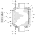
- FIG. 1 is a schematic cross-sectional view of a gas adsorption device according to Embodiment 1.
- FIG. It is a perspective view of a partially broken adsorption container.
- FIG. 2 is a schematic cross-sectional view of a gas adsorption device according to a second embodiment.
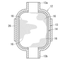
- FIG. 3 is a schematic cross-sectional view of an adsorption container according to Embodiment 3.
- the vertical direction corresponds to the vertical direction of the gas adsorption device, that is, the vertical direction.
- the gas adsorption device 10 includes an adsorption container 12, an adsorbent 16, and an electromagnetic wave generator 18.
- the adsorption container 12 is formed into a vertical hollow cylindrical shape.
- An upper opening 13a is provided at the upper end of the adsorption container 12 to communicate the inside and outside of the adsorption container 12.
- a lower opening 13b is provided at the lower end of the adsorption container 12 to communicate the inside and outside of the adsorption container 12.
- the upper port 13a is used as a gas inlet for the mixed gas
- the lower port 13b is used as a gas outlet.
- the mixed gas is, for example, the atmosphere, exhaust gas from a combustion engine, or the like. Details of the adsorption container 12 will be explained later.
- the adsorbent 16 is filled and housed in the adsorption container 12.
- the adsorbent 16 is capable of adsorbing and desorbing adsorbent substances such as carbon dioxide (CO2), for example.
- CO2 carbon dioxide
- a substance that is easily dielectrically heated is used.
- the adsorbent 16 includes, for example, zeolite, silica gel, activated carbon, and the like.
- the shape of the adsorbent 16 is, for example, granular, pellet, powder, honeycomb, or the like.
- the electromagnetic wave generator 18 irradiates electromagnetic waves (see arrows in FIG. 1) toward the adsorption container 12 when the adsorbent is desorbed from the adsorbent 16.
- the adsorbent 16 and adsorption container 12 are dielectrically heated by electromagnetic waves.
- the adsorption container 12 includes a container body 13 and a temperature drop suppressing member 14.
- the container body 13 forms the main body of the adsorption container 12, and has an upper opening 13a and a lower opening 13b.
- the container body 13 is made of, for example, polytetrafluoroethylene (PTFE) resin, quartz glass, or the like.
- the temperature drop suppressing member 14 is formed in a cylindrical shape so as to substantially entirely cover the inner circumferential surface of the container body 13.
- the temperature drop suppressing member 14 has a dielectric loss coefficient larger than that of the container body 13. That is, the temperature drop suppressing member 14 is made of a material that is more easily dielectrically heated than the container body 13. In other words, the container body 13 is made of a material that is less susceptible to dielectric heating than the temperature drop suppressing member 14 .
- the temperature drop suppressing member 14 is made of, for example, alumina.
- the temperature drop suppressing member 14 may be provided on the inner wall surface of at least a portion of the container body 13 that is irradiated with electromagnetic waves.
- a mixed gas containing adsorbent material e.g. carbon dioxide
- adsorbent material e.g. carbon dioxide
- the adsorbent substance is adsorbed by the adsorbent 16 in the adsorption container 12 .
- the gas from which the adsorbed substance has been removed is discharged from the lower port 13b to the outside of the adsorption container 12, and is supplied to the destination.
- the gas flow during desorption is in the same direction as the gas flow during adsorption. That is, the desorption gas is introduced into the adsorption container 12 from the desorption gas supply source through the upper port 13a.
- the adsorbed substance is desorbed from the adsorbent 16 in the adsorption container 12 .
- the electromagnetic wave generator 18 irradiates electromagnetic waves toward the adsorption container 12 .
- the adsorbent 16 is dielectrically heated by electromagnetic waves. This promotes the desorption efficiency of the adsorbed substance from the adsorbent 16.
- the adsorbent 16 is heated to an internal temperature of 150 to 200°C.
- the power of the electromagnetic wave is, for example, 100 to 2000 watts.
- the gas containing the adsorbed substance is discharged from the lower port 13b to the outside of the adsorption container 12, and is supplied to the destination.
- the electromagnetic wave generator 18 dielectrically heats the adsorbent 16 during desorption of the adsorbent.
- the container body 13 of the adsorption container 12 is not dielectrically heated or is hardly dielectrically heated.
- the temperature drop suppressing member 14 of the adsorption container 12 is dielectrically heated.
- Embodiment 2 is a modification of Embodiment 1, so the modified portion will be explained.
- the same parts as those in Embodiment 1 are given the same reference numerals and redundant explanations will be omitted.
- the second embodiment has a container inner wall 15 provided inside the container body 13 in place of the temperature drop suppressing member 14 of the first embodiment.
- the inner wall 15 of the container can be made of any of the following materials: a material that is not dielectrically heated, a material that is the same as the container body 13, a material that is less dielectrically heated than the container body 13, and a material that is more easily dielectrically heated than the container body 13. Good too.
- the material of the inner wall 15 of the container is the same material as the temperature drop suppressing member 14 of Embodiment 1 (see FIG. 1), a material that is less susceptible to dielectric heating than the temperature drop suppressing member 14, and a material that is less likely to be dielectrically heated than the temperature drop suppressing member 14. It may be formed of any material that is easily dielectrically heated.
- a cylindrical and sealed storage section 20 capable of storing the liquid L is formed between the container body 13 and the container inner wall 15.
- An injection pipe 21 for injecting the liquid L into the reservoir 20 is installed at the upper end of the container body 13 .
- the injection pipe 21 is provided with an injection valve 22 .
- a discharge pipe 23 for discharging the liquid L from the storage section 20 is installed at the lower end of the container body 13 .
- the discharge pipe 23 is provided with a discharge valve 24 .
- the liquid L is, for example, water, methanol, or the like.
- the discharge valve 24 When injecting the liquid L into the storage section 20, the discharge valve 24 is closed and the injection valve 22 is opened. As a result, the liquid L is injected from the liquid supply source into the storage section 20 via the injection pipe 21 and stored therein. After injecting the liquid L into the reservoir 20, the injection valve 22 is closed. Further, when discharging the liquid L from the storage section 20, the discharge valve 24 is opened. Thereby, the liquid L is discharged from the storage section 20 to a predetermined discharge destination via the discharge pipe 23. That is, the storage section 20 is capable of injecting and discharging the liquid L.
- the adsorbed substance is desorbed while the liquid L is injected and stored in the storage section 20 of the adsorption container 12.
- the adsorbent 16 is dielectrically heated by the electromagnetic wave generator 18 .
- the container body 13 and container inner wall 15 of the adsorption container 12 are not dielectrically heated or are not easily dielectrically heated.
- the liquid L is dielectrically heated.
- the efficiency of desorption of the adsorbed substance from the adsorbent 16 can be improved. Further, after the adsorbed substance is desorbed, the liquid in the storage section 20 is discharged. Thereby, the temperature of the adsorption container 12 can be reduced, and the lead time until the next adsorption step can be shortened.
- Embodiment 3 is a modification of Embodiment 1, so the modified portion will be explained.
- the same parts as those in Embodiment 1 are given the same reference numerals and redundant explanations will be omitted.
- the adsorption container 12 includes a cylindrical (for example, cylindrical) heat insulating member 26 that covers the outer peripheral surface of the container body 13.
- the heat insulating member 26 only needs to cover at least a portion of the container body 13.
- the heat insulating member 26 is made of glass wool or the like that is not easily heated by dielectric.
- the container body 13 of the adsorption container 12 can be kept warm by the heat insulating member 26.
- the technology disclosed in this specification is not limited to the embodiments described above, and can be implemented in various other forms.
- the lower port 13b of the adsorption container 12 may be used as a gas inlet, and the upper port 13a may be used as a gas outlet for mixed gas.
- the adsorption container 12 may be arranged with its axial direction directed in a direction other than the vertical direction.
- the container body 13 is not limited to a single layer structure made of one material, but may have a multilayer structure made of a plurality of materials.
- the temperature drop suppressing member 14 may be formed by coating the inner circumferential surface of the container body 13.
- the temperature drop suppressing member 14 is not limited to a single layer structure made of one material, but may have a multilayer structure made of a plurality of materials.
- the gas flow during desorption may be in the opposite direction to the gas flow during adsorption.
- the heat insulating member 26 only needs to cover at least a portion of the container body 13, and may be provided so as to cover the entire container body 13.
- the heat insulating member 26 is not limited to a single layer structure made of one material, but may have a multilayer structure made of a plurality of materials.
Landscapes
- Chemical & Material Sciences (AREA)
- Engineering & Computer Science (AREA)
- Analytical Chemistry (AREA)
- General Chemical & Material Sciences (AREA)
- Oil, Petroleum & Natural Gas (AREA)
- Chemical Kinetics & Catalysis (AREA)
- Separation Of Gases By Adsorption (AREA)
Abstract
ガス吸着装置(10)は、吸着物質を吸着する吸着材(16)と、吸着材(16)を収容する吸着容器(12)を備える。さらにガス吸着装置(10)は、吸着材(16)を誘電加熱する電磁波発生装置(18)を備える。吸着容器(12)は、容器本体(13)と、容器本体(13)の少なくとも電磁波が照射される部分と吸着材(16)との間に設けられる温度低下抑制部材(14)と、を有する。温度低下抑制部材(14)は、容器本体(13)の誘電損失係数よりも大きい誘電損失係数を有する。
Description
本明細書に開示の技術はガス吸着装置に関する。
従来、例えば特開平10-305207号公報(以下207号公報という)にガス吸着装置が開示されている。そのガス吸着装置は、吸着物質を吸着する吸着材と、吸着材を収容する吸着容器を備える。さらにガス吸着装置は、吸着容器に向けて電磁波を照射することにより吸着材を誘電加熱する電磁波発生装置を備える。吸着物質の脱離時に吸着材を誘電加熱することにより、吸着物質の吸着材からの脱離を促進する。
207号公報の吸着容器は、一層構造である。そのため、吸着物質の脱離時に吸着材を加熱しても、その吸着材の熱が吸着容器に奪われやすい。したがって、吸着材の温度が低下しやすく、脱離の促進が損なわれるという問題があった。
そのため吸着物質の脱離時における吸着材の温度の低下を抑制し、吸着物質の吸着材からの脱離効率を向上する構造が従来必要であった。
本開示の1つの特徴によると、ガス吸着装置は、吸着物質を吸着する吸着材と、前記吸着材を収容する吸着容器を備える。さらにガス吸着装置は、前記吸着容器に向けて電磁波を照射することにより前記吸着材を誘電加熱する電磁波発生装置を備える。前記吸着容器は、容器本体と、該容器本体の少なくとも前記電磁波が照射される部分と前記吸着材との間に設けられる温度低下抑制部材と、を有している。前記温度低下抑制部材は、前記容器本体の誘電損失係数よりも大きい誘電損失係数を有する。
吸着物質の脱離時において、電磁波発生装置により吸着材を誘電加熱する。この時、吸着容器の容器本体は誘電加熱されない又は誘電加熱されにくい。一方、吸着容器の温度低下抑制部材は誘電加熱される。これにより、温度低下抑制部材の熱が吸着容器の容器本体に奪われるとしても、温度低下抑制部材の近傍の吸着材の温度の低下を抑制することができる。よって、脱離効率を向上することができる。
本開示の他の1つの特徴によると、ガス吸着装置は、吸着物質を吸着する吸着材と、前記吸着材を収容する吸着容器を備える。さらにガス吸着装置は、前記吸着容器に向けて電磁波を照射することにより前記吸着材を誘電加熱する電磁波発生装置を備える。前記吸着容器は、容器本体と、該容器本体の内側に設けられる容器内壁と、を備えている。前記容器本体と前記容器内壁との間には、液体を貯留可能でかつ該液体を注入及び排出可能な貯留部が設けられている。
吸着容器の貯留部に液体を注入により貯留した状態で、吸着物質の脱離を行う。吸着物質の脱離時において、電磁波発生装置により吸着材を誘電加熱する。この際、吸着容器の容器本体及び容器内壁は誘電加熱されない又は誘電加熱されにくい。一方、液体は誘電加熱される。これにより、液体の熱が容器本体に奪われるとしても、容器内壁の近傍の吸着材の温度の低下を抑制することができる。よって、脱離効率を向上することができる。また、吸着物質の脱離後、貯留部の液体を排出することにより、吸着容器の温度低下を促進できる。その結果、次回の吸着工程までのリードタイムを短縮することができる。また、容器内壁は、誘電加熱されない材料、容器本体と同等の材料、容器本体と比べて誘電加熱されにくい材料、容器本体と比べて誘電加熱されやすい材料、のいずれの材料で形成してもよい。
本開示の他の1つの特徴によると、前記吸着容器は、前記容器本体の少なくとも一部を覆う断熱部材を備えている。そのため、断熱部材により吸着容器の容器本体を保温することができる。
以下、本明細書に開示の技術を実施するための実施形態について図面を用いて説明する。
[実施形態1]
図1において、上下方向はガス吸着装置の鉛直方向すなわち上下方向に対応する。図1に示すように、ガス吸着装置10は、吸着容器12と吸着材16と電磁波発生装置18とを備えている。
図1において、上下方向はガス吸着装置の鉛直方向すなわち上下方向に対応する。図1に示すように、ガス吸着装置10は、吸着容器12と吸着材16と電磁波発生装置18とを備えている。
(吸着容器12)
吸着容器12は縦型中空円筒状に形成されている。吸着容器12の上端部には、吸着容器12の内部と外部を連通させる上部口13aが設けられている。吸着容器12の下端部には、吸着容器12の内部と外部を連通させる下部口13bが設けられている。本実施形態においては、上部口13aを混合ガスのガス入口とし、下部口13bをガス出口とする。混合ガスは、例えば、大気、燃焼機関の排ガス等である。吸着容器12の詳細については後で説明する。
吸着容器12は縦型中空円筒状に形成されている。吸着容器12の上端部には、吸着容器12の内部と外部を連通させる上部口13aが設けられている。吸着容器12の下端部には、吸着容器12の内部と外部を連通させる下部口13bが設けられている。本実施形態においては、上部口13aを混合ガスのガス入口とし、下部口13bをガス出口とする。混合ガスは、例えば、大気、燃焼機関の排ガス等である。吸着容器12の詳細については後で説明する。
(吸着材16)
吸着材16は、吸着容器12内に充填されて収容されている。吸着材16は、例えば、二酸化炭素(CO2)等の吸着物質を吸着及び脱離可能である。吸着材16には、誘電加熱されやすい物質が用いられる。吸着材16は、例えば、ゼオライト、シリカゲル、活性炭等を含む。吸着材16の形状は、例えば、粒状、ペレット状、粉末状、ハニカム状等である。
吸着材16は、吸着容器12内に充填されて収容されている。吸着材16は、例えば、二酸化炭素(CO2)等の吸着物質を吸着及び脱離可能である。吸着材16には、誘電加熱されやすい物質が用いられる。吸着材16は、例えば、ゼオライト、シリカゲル、活性炭等を含む。吸着材16の形状は、例えば、粒状、ペレット状、粉末状、ハニカム状等である。
(電磁波発生装置18)
電磁波発生装置18は、吸着物質の吸着材16からの脱離時において、電磁波(図1中、矢印参照)を吸着容器12に向けて照射する。電磁波により吸着材16及び吸着容器12を誘電加熱する。
電磁波発生装置18は、吸着物質の吸着材16からの脱離時において、電磁波(図1中、矢印参照)を吸着容器12に向けて照射する。電磁波により吸着材16及び吸着容器12を誘電加熱する。
(吸着容器12の構造)
図1、2に示すように、吸着容器12は、容器本体13と温度低下抑制部材14とを有する。容器本体13は、吸着容器12の主体をなすものであり、上部口13a及び下部口13bを有する。容器本体13は、例えば、ポリテトラフルオロエチレン(PTFE)樹脂、石英ガラス等により形成されている。
図1、2に示すように、吸着容器12は、容器本体13と温度低下抑制部材14とを有する。容器本体13は、吸着容器12の主体をなすものであり、上部口13a及び下部口13bを有する。容器本体13は、例えば、ポリテトラフルオロエチレン(PTFE)樹脂、石英ガラス等により形成されている。
温度低下抑制部材14は、容器本体13の内周面を略全面的に覆うように円筒状に形成されている。温度低下抑制部材14は、容器本体13の誘電損失係数よりも大きい誘電損失係数を有する。すなわち、温度低下抑制部材14は、容器本体13と比べて、誘電加熱されやすい材料により形成されている。言い換えれば、容器本体13は、温度低下抑制部材14と比べて、誘電加熱されにくい材料により形成されている。温度低下抑制部材14は、例えばアルミナ等により形成されている。温度低下抑制部材14は、容器本体13の少なくとも電磁波が照射される部分の内壁面に設けられていればよい。
(ガス吸着装置10の作用)
〈吸着時〉
吸着物質(例えば二酸化炭素)を含む混合ガスが混合ガス供給源から上部口13aを介して吸着容器12に導入される。吸着物質が吸着容器12内の吸着材16に吸着される。吸着物質が除去されたガスは、下部口13bから吸着容器12の外へ排出され、供給先へ供給される。
〈吸着時〉
吸着物質(例えば二酸化炭素)を含む混合ガスが混合ガス供給源から上部口13aを介して吸着容器12に導入される。吸着物質が吸着容器12内の吸着材16に吸着される。吸着物質が除去されたガスは、下部口13bから吸着容器12の外へ排出され、供給先へ供給される。
〈脱離時〉
脱離時のガスの流れは、吸着時のガスの流れと同方向である。すなわち、脱離用ガスが脱離用ガス供給源から上部口13aを介して吸着容器12に導入される。吸着容器12内において吸着材16から吸着物質が脱離される。電磁波発生装置18により吸着容器12に向けて電磁波を照射する。電磁波により吸着材16を誘電加熱する。これにより吸着材16からの吸着物質の脱離効率が促進される。例えば、吸着材16は、内部温度が150~200℃に加熱される。電磁波の電力は、例えば、100~2000ワットである。吸着物質を含むガスは、下部口13bから吸着容器12の外へ排出され、供給先へ供給される。
脱離時のガスの流れは、吸着時のガスの流れと同方向である。すなわち、脱離用ガスが脱離用ガス供給源から上部口13aを介して吸着容器12に導入される。吸着容器12内において吸着材16から吸着物質が脱離される。電磁波発生装置18により吸着容器12に向けて電磁波を照射する。電磁波により吸着材16を誘電加熱する。これにより吸着材16からの吸着物質の脱離効率が促進される。例えば、吸着材16は、内部温度が150~200℃に加熱される。電磁波の電力は、例えば、100~2000ワットである。吸着物質を含むガスは、下部口13bから吸着容器12の外へ排出され、供給先へ供給される。
(実施形態1の作用・効果)
本実施形態によると、吸着物質の脱離時において、電磁波発生装置18により吸着材16を誘電加熱する。この際、吸着容器12の容器本体13は誘電加熱されない又は誘電加熱されにくい。一方、吸着容器12の温度低下抑制部材14は誘電加熱される。これにより、温度低下抑制部材14の熱が吸着容器12の容器本体13に奪われるとしても、温度低下抑制部材14の近傍の吸着材16の温度の低下を抑制することができる。よって、脱離効率を向上することができる。
本実施形態によると、吸着物質の脱離時において、電磁波発生装置18により吸着材16を誘電加熱する。この際、吸着容器12の容器本体13は誘電加熱されない又は誘電加熱されにくい。一方、吸着容器12の温度低下抑制部材14は誘電加熱される。これにより、温度低下抑制部材14の熱が吸着容器12の容器本体13に奪われるとしても、温度低下抑制部材14の近傍の吸着材16の温度の低下を抑制することができる。よって、脱離効率を向上することができる。
[実施形態2]
実施形態2は、実施形態1に変更を加えたものであるから、その変更部分について説明する。実施形態1と同一部位については同一符号を付して重複する説明を省略する。図3に示すように、実施形態2は、実施形態1の温度低下抑制部材14に代えて、容器本体13の内側に設けられる容器内壁15を有している。容器内壁15は、誘電加熱されない材料、容器本体13と同等の材料、容器本体13と比べて誘電加熱されにくい材料、容器本体13と比べて誘電加熱されやすい材料、のいずれの材料で形成してもよい。また、容器内壁15の材料は、実施形態1(図1参照)の温度低下抑制部材14と同等の材料、温度低下抑制部材14と比べて誘電加熱されにくい材料、温度低下抑制部材14と比べて誘電加熱されやすい材料、のいずれの材料で形成してもよい。
実施形態2は、実施形態1に変更を加えたものであるから、その変更部分について説明する。実施形態1と同一部位については同一符号を付して重複する説明を省略する。図3に示すように、実施形態2は、実施形態1の温度低下抑制部材14に代えて、容器本体13の内側に設けられる容器内壁15を有している。容器内壁15は、誘電加熱されない材料、容器本体13と同等の材料、容器本体13と比べて誘電加熱されにくい材料、容器本体13と比べて誘電加熱されやすい材料、のいずれの材料で形成してもよい。また、容器内壁15の材料は、実施形態1(図1参照)の温度低下抑制部材14と同等の材料、温度低下抑制部材14と比べて誘電加熱されにくい材料、温度低下抑制部材14と比べて誘電加熱されやすい材料、のいずれの材料で形成してもよい。
容器本体13と容器内壁15との間には、液体Lを貯留可能な円筒状でかつ密閉状の貯留部20が形成されている。容器本体13の上端部には、貯留部20に液体Lを注入する注入管21が配管されている。注入管21には注入バルブ22が設けられている。容器本体13の下端部には、貯留部20から液体Lを排出する排出管23が配管されている。排出管23には排出バルブ24が設けられている。液体Lは、例えば、水、メタノール等である。
貯留部20に液体Lを注入する際は、排出バルブ24を閉じ、注入バルブ22を開ける。これにより、液体Lが液体供給源から注入管21を介して貯留部20に注入されて貯留される。貯留部20に液体Lを注入し終えたら注入バルブ22を閉じる。また、貯留部20から液体Lを排出する際は、排出バルブ24を開ける。これにより、液体Lが貯留部20から排出管23を介して所定の排出先に排出される。すなわち、貯留部20は、液体Lを注入及び排出可能になっている。
実施形態2によると、吸着容器12の貯留部20に液体Lを注入により貯留した状態で、吸着物質の脱離を行う。吸着物質の脱離時において、電磁波発生装置18により吸着材16を誘電加熱する。この際、吸着容器12の容器本体13及び容器内壁15は誘電加熱されない又は誘電加熱されにくい。一方、液体Lは誘電加熱される。これにより、液体Lの熱が吸着容器本体13に奪われるとしても、容器内壁15の近傍の吸着材16の温度の低下を抑制することができる。よって、吸着材16からの吸着物質の脱離効率を向上することができる。また、吸着物質の脱離後、貯留部20の液体を排出する。これにより、吸着容器12の温度低下を促進し、次回の吸着工程までのリードタイムを短縮することができる。
[実施形態3]
実施形態3は、実施形態1に変更を加えたものであるから、その変更部分について説明する。実施形態1と同一部位については同一符号を付して重複する説明を省略する。図4に示すように、吸着容器12は、容器本体13の外周面を覆う筒状(例えば円筒状)の断熱部材26を備えている。断熱部材26は、容器本体13の少なくとも一部を覆うものであればよい。断熱部材26は、誘電加熱されにくいガラスウール等により形成されている。
実施形態3は、実施形態1に変更を加えたものであるから、その変更部分について説明する。実施形態1と同一部位については同一符号を付して重複する説明を省略する。図4に示すように、吸着容器12は、容器本体13の外周面を覆う筒状(例えば円筒状)の断熱部材26を備えている。断熱部材26は、容器本体13の少なくとも一部を覆うものであればよい。断熱部材26は、誘電加熱されにくいガラスウール等により形成されている。
実施形態3によると、断熱部材26により吸着容器12の容器本体13を保温することができる。
[他の実施形態]
本明細書に開示の技術は、前記した実施形態に限定されるものではなく、その他各種の形態で実施可能である。例えば、吸着容器12の下部口13bをガス入口とし、上部口13aを混合ガスのガス出口としてもよい。また、吸着容器12は、その軸方向を鉛直方向以外の方向に向けて配置してもよい。また、容器本体13は、一つの素材から構成される一層構造に限定されるものではなく、複数の素材から構成される多層構造でもよい。また、温度低下抑制部材14は、容器本体13の内周面にコーティングすることにより形成してもよい。また、温度低下抑制部材14は、一つの素材から構成される一層構造に限定されるものではなく、複数の素材から構成される多層構造でもよい。また、脱離時のガスの流れは、吸着時のガスの流れと逆方向でもよい。また、断熱部材26は、容器本体13の少なくとも一部を覆うものであればよく、容器本体13全体を覆うように設けてもよい。また、断熱部材26は、一つの素材から構成される一層構造に限定されるものではなく、複数の素材から構成される多層構造でもよい。
本明細書に開示の技術は、前記した実施形態に限定されるものではなく、その他各種の形態で実施可能である。例えば、吸着容器12の下部口13bをガス入口とし、上部口13aを混合ガスのガス出口としてもよい。また、吸着容器12は、その軸方向を鉛直方向以外の方向に向けて配置してもよい。また、容器本体13は、一つの素材から構成される一層構造に限定されるものではなく、複数の素材から構成される多層構造でもよい。また、温度低下抑制部材14は、容器本体13の内周面にコーティングすることにより形成してもよい。また、温度低下抑制部材14は、一つの素材から構成される一層構造に限定されるものではなく、複数の素材から構成される多層構造でもよい。また、脱離時のガスの流れは、吸着時のガスの流れと逆方向でもよい。また、断熱部材26は、容器本体13の少なくとも一部を覆うものであればよく、容器本体13全体を覆うように設けてもよい。また、断熱部材26は、一つの素材から構成される一層構造に限定されるものではなく、複数の素材から構成される多層構造でもよい。
Claims (3)
- ガス吸着装置であって、
吸着物質を吸着する吸着材と、
前記吸着材を収容する吸着容器と、
前記吸着容器に向けて電磁波を照射することにより前記吸着材を誘電加熱する電磁波発生装置と、を備え、
前記吸着容器は、容器本体と、該容器本体の少なくとも前記電磁波が照射される部分と前記吸着材との間に設けられる温度低下抑制部材と、を有しており、
前記温度低下抑制部材は、前記容器本体の誘電損失係数よりも大きい誘電損失係数を有する、ガス吸着装置。 - ガス吸着装置であって、
吸着物質を吸着する吸着材と、
前記吸着材を収容する吸着容器と、
前記吸着容器に向けて電磁波を照射することにより前記吸着材を誘電加熱する電磁波発生装置と、を備え、
前記吸着容器は、容器本体と、該容器本体の内側に設けられる容器内壁と、を備えており、
前記容器本体と前記容器内壁との間には、液体を貯留可能でかつ該液体を注入及び排出可能な貯留部が設けられている、ガス吸着装置。 - 請求項1又は2に記載のガス吸着装置であって、
前記吸着容器は、前記容器本体の少なくとも一部を覆う断熱部材を備えている、ガス吸着装置。
Applications Claiming Priority (2)
| Application Number | Priority Date | Filing Date | Title |
|---|---|---|---|
| JP2022-077351 | 2022-05-10 | ||
| JP2022077351A JP2023166687A (ja) | 2022-05-10 | 2022-05-10 | ガス吸着装置 |
Publications (1)
| Publication Number | Publication Date |
|---|---|
| WO2023218762A1 true WO2023218762A1 (ja) | 2023-11-16 |
Family
ID=88730021
Family Applications (1)
| Application Number | Title | Priority Date | Filing Date |
|---|---|---|---|
| PCT/JP2023/011105 Ceased WO2023218762A1 (ja) | 2022-05-10 | 2023-03-22 | ガス吸着装置 |
Country Status (2)
| Country | Link |
|---|---|
| JP (1) | JP2023166687A (ja) |
| WO (1) | WO2023218762A1 (ja) |
Citations (9)
| Publication number | Priority date | Publication date | Assignee | Title |
|---|---|---|---|---|
| JPS5235194A (en) * | 1975-09-12 | 1977-03-17 | Toyobo Co Ltd | Method for regeneration of active carbon |
| JPS5318504A (en) * | 1976-08-05 | 1978-02-20 | Shin Etsu Chem Co Ltd | Recovery of halogenated hydrocarbons |
| US4421651A (en) * | 1982-05-28 | 1983-12-20 | Iowa State University Research Foundation, Inc. | Method of recovering adsorbed liquid compounds from molecular sieve columns |
| US5282886A (en) * | 1991-09-13 | 1994-02-01 | Director-General Of Agency Of Industrial Science And Technology | Gas adsorption and desorption method |
| JP2006522435A (ja) * | 2003-01-27 | 2006-09-28 | ダルトン,ロバート,シー. | 電磁石コーティングとサセプタのための人工誘電性システムおよび関連装置の適用へのクロスレファレンス |
| US20070257029A1 (en) * | 2006-05-02 | 2007-11-08 | Opperman Stephen H | Microwave heating system and method for removing volatiles from adsorbent materials |
| JP2009006277A (ja) * | 2007-06-28 | 2009-01-15 | National Institute Of Advanced Industrial & Technology | 高周波加熱式吸着塔 |
| JP2009045535A (ja) * | 2007-08-17 | 2009-03-05 | Osaka Univ | 揮発性有機化合物の回収ユニット |
| JP2015128742A (ja) * | 2014-01-07 | 2015-07-16 | マイクロ波化学株式会社 | 化学反応装置、及び化学反応方法 |
-
2022
- 2022-05-10 JP JP2022077351A patent/JP2023166687A/ja active Pending
-
2023
- 2023-03-22 WO PCT/JP2023/011105 patent/WO2023218762A1/ja not_active Ceased
Patent Citations (9)
| Publication number | Priority date | Publication date | Assignee | Title |
|---|---|---|---|---|
| JPS5235194A (en) * | 1975-09-12 | 1977-03-17 | Toyobo Co Ltd | Method for regeneration of active carbon |
| JPS5318504A (en) * | 1976-08-05 | 1978-02-20 | Shin Etsu Chem Co Ltd | Recovery of halogenated hydrocarbons |
| US4421651A (en) * | 1982-05-28 | 1983-12-20 | Iowa State University Research Foundation, Inc. | Method of recovering adsorbed liquid compounds from molecular sieve columns |
| US5282886A (en) * | 1991-09-13 | 1994-02-01 | Director-General Of Agency Of Industrial Science And Technology | Gas adsorption and desorption method |
| JP2006522435A (ja) * | 2003-01-27 | 2006-09-28 | ダルトン,ロバート,シー. | 電磁石コーティングとサセプタのための人工誘電性システムおよび関連装置の適用へのクロスレファレンス |
| US20070257029A1 (en) * | 2006-05-02 | 2007-11-08 | Opperman Stephen H | Microwave heating system and method for removing volatiles from adsorbent materials |
| JP2009006277A (ja) * | 2007-06-28 | 2009-01-15 | National Institute Of Advanced Industrial & Technology | 高周波加熱式吸着塔 |
| JP2009045535A (ja) * | 2007-08-17 | 2009-03-05 | Osaka Univ | 揮発性有機化合物の回収ユニット |
| JP2015128742A (ja) * | 2014-01-07 | 2015-07-16 | マイクロ波化学株式会社 | 化学反応装置、及び化学反応方法 |
Also Published As
| Publication number | Publication date |
|---|---|
| JP2023166687A (ja) | 2023-11-22 |
Similar Documents
| Publication | Publication Date | Title |
|---|---|---|
| JP2596169B2 (ja) | 冷却器 | |
| DK152018B (da) | Fremgangsmaade og apparat til gasfraktionering med varmereaktivering | |
| JP3788152B2 (ja) | 内燃機関のキャニスタ | |
| JPH10332091A (ja) | 気体貯蔵ならびに計量分配装置 | |
| JP7494800B2 (ja) | ゲストフリーシリコンクラスレートの製造方法、ゲストフリーシリコンクラスレートの製造装置 | |
| JPH11311117A (ja) | 触媒加熱装置 | |
| US5482541A (en) | Sorption cartridge | |
| JPS61227821A (ja) | 炭酸ガスの除去方法 | |
| JP2023166687A (ja) | ガス吸着装置 | |
| CN205618970U (zh) | 低温液体储罐真空夹层吸附干燥结构 | |
| JP4951017B2 (ja) | 吸着式ガス処理装置 | |
| JP2011104547A (ja) | 排ガス処理装置、及び排ガス処理方法 | |
| JP2005325708A (ja) | キャニスタ | |
| CN116036791A (zh) | 一种废气处理装置 | |
| JP3971492B2 (ja) | 非熱プラズマによる脱離・再生方法 | |
| CN205700032U (zh) | 废气处理用活性炭吸附与再生装置 | |
| CN102365449A (zh) | 特别是用于汽车的用于干燥燃料的装置和方法 | |
| JP2010096118A (ja) | 蒸発燃料処理装置 | |
| CN113027640A (zh) | 燃料吸附装置及使用该燃料吸附装置的蒸发燃料处理设备 | |
| CA2651084A1 (en) | Microwave heating system and method for removing volatiles from adsorbent materials | |
| JP2005325707A (ja) | キャニスタ | |
| JP4439995B2 (ja) | キャニスタ | |
| JP7840789B2 (ja) | 吸着装置 | |
| WO2003080237A1 (en) | Method for regenerating adsorbent by heating | |
| CN117497948A (zh) | 电池包安全阀及电池包 |
Legal Events
| Date | Code | Title | Description |
|---|---|---|---|
| 121 | Ep: the epo has been informed by wipo that ep was designated in this application |
Ref document number: 23803245 Country of ref document: EP Kind code of ref document: A1 |
|
| NENP | Non-entry into the national phase |
Ref country code: DE |
|
| 122 | Ep: pct application non-entry in european phase |
Ref document number: 23803245 Country of ref document: EP Kind code of ref document: A1 |