WO2023218706A1 - 固形薬剤収容体及び水処理方法 - Google Patents
固形薬剤収容体及び水処理方法 Download PDFInfo
- Publication number
- WO2023218706A1 WO2023218706A1 PCT/JP2023/003729 JP2023003729W WO2023218706A1 WO 2023218706 A1 WO2023218706 A1 WO 2023218706A1 JP 2023003729 W JP2023003729 W JP 2023003729W WO 2023218706 A1 WO2023218706 A1 WO 2023218706A1
- Authority
- WO
- WIPO (PCT)
- Prior art keywords
- water
- solid drug
- container
- film
- accommodation space
- Prior art date
- Legal status (The legal status is an assumption and is not a legal conclusion. Google has not performed a legal analysis and makes no representation as to the accuracy of the status listed.)
- Ceased
Links
Images

Classifications
-
- C—CHEMISTRY; METALLURGY
- C02—TREATMENT OF WATER, WASTE WATER, SEWAGE, OR SLUDGE
- C02F—TREATMENT OF WATER, WASTE WATER, SEWAGE, OR SLUDGE
- C02F1/00—Treatment of water, waste water, or sewage
- C02F1/68—Treatment of water, waste water, or sewage by addition of specified substances, e.g. trace elements, for ameliorating potable water
- C02F1/685—Devices for dosing the additives
- C02F1/688—Devices in which the water progressively dissolves a solid compound
-
- B—PERFORMING OPERATIONS; TRANSPORTING
- B01—PHYSICAL OR CHEMICAL PROCESSES OR APPARATUS IN GENERAL
- B01F—MIXING, e.g. DISSOLVING, EMULSIFYING OR DISPERSING
- B01F21/00—Dissolving
-
- B—PERFORMING OPERATIONS; TRANSPORTING
- B01—PHYSICAL OR CHEMICAL PROCESSES OR APPARATUS IN GENERAL
- B01F—MIXING, e.g. DISSOLVING, EMULSIFYING OR DISPERSING
- B01F23/00—Mixing according to the phases to be mixed, e.g. dispersing or emulsifying
- B01F23/50—Mixing liquids with solids
-
- B—PERFORMING OPERATIONS; TRANSPORTING
- B01—PHYSICAL OR CHEMICAL PROCESSES OR APPARATUS IN GENERAL
- B01F—MIXING, e.g. DISSOLVING, EMULSIFYING OR DISPERSING
- B01F35/00—Accessories for mixers; Auxiliary operations or auxiliary devices; Parts or details of general application
- B01F35/50—Mixing receptacles
- B01F35/53—Mixing receptacles characterised by the configuration of the interior, e.g. baffles for facilitating the mixing of components
-
- C—CHEMISTRY; METALLURGY
- C02—TREATMENT OF WATER, WASTE WATER, SEWAGE, OR SLUDGE
- C02F—TREATMENT OF WATER, WASTE WATER, SEWAGE, OR SLUDGE
- C02F1/00—Treatment of water, waste water, or sewage
-
- C—CHEMISTRY; METALLURGY
- C02—TREATMENT OF WATER, WASTE WATER, SEWAGE, OR SLUDGE
- C02F—TREATMENT OF WATER, WASTE WATER, SEWAGE, OR SLUDGE
- C02F1/00—Treatment of water, waste water, or sewage
- C02F1/72—Treatment of water, waste water, or sewage by oxidation
- C02F1/76—Treatment of water, waste water, or sewage by oxidation with halogens or compounds of halogens
-
- B—PERFORMING OPERATIONS; TRANSPORTING
- B01—PHYSICAL OR CHEMICAL PROCESSES OR APPARATUS IN GENERAL
- B01F—MIXING, e.g. DISSOLVING, EMULSIFYING OR DISPERSING
- B01F2101/00—Mixing characterised by the nature of the mixed materials or by the application field
- B01F2101/305—Treatment of water, waste water or sewage
-
- C—CHEMISTRY; METALLURGY
- C02—TREATMENT OF WATER, WASTE WATER, SEWAGE, OR SLUDGE
- C02F—TREATMENT OF WATER, WASTE WATER, SEWAGE, OR SLUDGE
- C02F2103/00—Nature of the water, waste water, sewage or sludge to be treated
- C02F2103/02—Non-contaminated water, e.g. for industrial water supply
- C02F2103/023—Water in cooling circuits
Definitions
- the present invention relates to a solid drug container containing a water-soluble solid drug, and specifically, a solid drug that has the function of gradually dissolving the water-soluble solid drug by contact with the water to be treated and releasing it into the water to be treated. Regarding the containment body.
- the present invention also relates to a water treatment method for treating water using this solid drug container.
- Patent Document 1 discloses a storage space that can accommodate a plurality of water-soluble solid drugs, and a storage space that allows the water to be treated to flow into the storage space. It has an inlet and an outlet for flowing out the water to be treated from the accommodation space, and a water-soluble solid drug is vertically stacked in the accommodation space with a water-soluble film interposed therebetween, and at least one of the water-soluble films is laminated in the accommodation space.
- a solid drug container is described in which a portion of the solid drug container is disposed above the inlet and the outlet.
- this solid drug container among the plurality of water-soluble solid drugs stored in the storage container, those that are not exposed to the flow path of the water to be treated formed between the inlet and the outlet of the storage container are Even when the drug directly below is dissolving, the presence of the water-soluble film reduces wetting, reducing the water content of the water-soluble solid drug compared to when used under the same conditions except for the presence of the water-soluble film. The residual rate of the active ingredient of the drug can be increased.
- the water-soluble film is dissolved by moisture (water vapor, water droplets, rising water due to capillary action, etc.), and the solid drug on the upper side of the film absorbs moisture and swells. and sometimes formed a bridge.
- Patent Document 2 describes a method for preventing bridging by placing a weight (drop lid) on the top of a solid drug filled in a container and pushing down the solid drug with the weight of the weight.
- Patent Document 3 describes, as a device for continuous and automatic elution, a solid drug continuous automatic elution device equipped with a solid drug eluator having a perforated inclined surface.
- the present invention provides a solid drug container configured to suppress the solid drug from forming bridges and gradually dissolve the entire amount of the solid drug, and a water treatment method using this solid drug container.
- the task is to
- the solid drug container of the present invention includes a storage container that has a storage space that can accommodate a plurality of water-soluble solid drugs, an inlet that allows water to flow into the storage space, and an outlet that allows water to flow out from the storage space.
- a solid drug container in which water-soluble solid drugs are stacked and arranged in the storage space is characterized in that a water-insoluble film is interposed between the layers of the solid drugs.
- the storage container includes a container body formed by fitting an upper member and a lower member, a partition wall that divides the inside of the container body into the accommodation space and the non-accommodation space;
- a partition wall communication path that communicates the accommodation space and the non-accommodation space so that water can flow between the accommodation space and the non-accommodation space, and functions as the inlet and outlet, and the inside and outside of the storage container. It has a container communication path that communicates with the container body and allows water to flow between the outside of the container body and the non-accommodating space.
- the water-insoluble film is a synthetic resin film.
- the synthetic resin is polyethylene or polyvinyl chloride.
- the area of the film is 1/2 or more, particularly preferably 80% or more, of the horizontal cross-sectional area of the accommodation space.
- the water treatment method of the present invention is a water treatment method in which a solid drug is dissolved and added to water to be treated. is added to the water to be treated.
- the solid drug container of the present invention by interposing a water-insoluble film between the solid drug layers, transmission of moisture (water vapor, water droplets, rising water due to capillary action, etc.) to the solid drug on the upper side of the film is suppressed. This suppresses the swelling of the solid drug. As a result, the formation of bridges by the solid drug is suppressed. Therefore, according to the solid drug container of the present invention and the water treatment method using this solid drug container, the components of the solid drug can be continuously dissolved in the water to be treated over a long period of time.
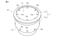
- FIG. 1 is a perspective view schematically showing a storage container according to one embodiment of a solid medicine container.
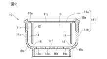
- FIG. 2 is a longitudinal cross-sectional view of the solid drug container shown in FIG. 1.
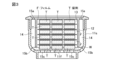
- FIG. 3 is a schematic explanatory diagram of a state in which a solid drug is filled into a solid drug container. It is an explanatory view of the state of dissolution of the solid drug in the solid drug container.
- the water to be treated is cooling water of a cooling tower, but the water to be treated may be other water such as circulating water of a swimming pool.
- the storage container for the solid drug accommodating body of the present invention has an inlet that allows the water to be treated to flow into the container, and an outlet that allows the water to be treated that has flowed into the container to flow out of the container.
- the storage container includes a cylindrical portion, an upper surface portion and a lower surface portion that seal both ends of the cylindrical portion, an inlet provided in the cylindrical portion and/or the lower surface portion, and an inlet provided in the cylindrical portion and/or the lower surface portion. and/or an outlet provided on the lower surface. Note that the inlet may also serve as the outlet.
- FIG. 1 is a perspective view showing an example of a storage container
- FIG. 2 is a longitudinal sectional view thereof.
- This storage container 10 has a container body 11 having a substantially cylindrical shape. As shown in FIG. 2, the inside of the container body 11 is divided by a cylindrical partition wall 12 into a storage space 13 that stores a water-soluble solid drug and a non-storage space 14 that does not store a water-soluble solid drug. There is.
- the container body 11 is composed of an upper member 11a and a lower member 11b.
- the upper member 11a has a top portion 11t, a cylindrical hanging wall 11r that hangs down from the outer peripheral edge of the top portion 11t, and a cylindrical partition wall 12 that hangs down from the top portion 11t.
- the hanging wall 11r and the partition wall 12 are coaxially provided.
- the lower member 11b has a bottom surface 11f and a side peripheral surface 11s.
- the hanging wall 11r, the partition wall 12, and the side circumferential surface 11s may have a shape other than a cylindrical shape, such as an elliptical shape, a square shape, or a polygonal shape having more than five sides.
- the upper member 11a and the lower member 11b have a structure (for example, a fitting structure) that allows them to be separated and easily integrated.
- the hanging wall 11r of the upper member 11a and the upper part of the side peripheral surface 11s of the lower member 11b are removably fitted together.
- a hole 15a serving as a container communication path through which water can flow is provided in the top portion 11t of the upper member 11a.
- the hole 15a is arranged between the partition wall 12 and the hanging wall 11r in the top portion 11t.
- a plurality of holes 15a are arranged at approximately equal intervals in the circumferential direction.
- the non-accommodating space 14 communicates with the outside above the storage container 10 through this hole 15a.
- a hole 15b serving as a container communication path through which water can flow is provided near the intersection of the side peripheral surface 11s and the bottom surface 11f of the lower member 11b.
- a plurality of holes 15b are arranged at approximately equal intervals in the circumferential direction.
- a hole 15c as a container communication path through which water can flow is provided in the bottom surface 11f of the lower member 11b.
- the plurality of holes 15c are arranged approximately evenly over the entire bottom surface 11f.
- the partition wall 12 is suspended from the top 11t of the upper member 11a.
- the inside of the partition wall 12 is the accommodation space 13.
- the diameter (inner diameter) of the partition wall 12 is preferably about 20 to 200 mm, particularly about 50 to 70 mm.
- the horizontal cross-sectional area of the accommodation space 13 is preferably about 300 to 30,000 mm 2 , particularly about 2,000 to 4,000 mm 2 .
- the outer diameter of the partition wall 12 is smaller than the inner diameter of the side circumferential surface 11s, and a non-accommodating space 14 is formed between the partition wall 12 and the side circumferential surface 11s.
- a gap between the lower end of the partition wall 12 and the opposing bottom surface 11f of the lower member 11b serves as a partition wall communication path 16 that communicates the accommodation space 13 and the non-accommodation space 14.
- the distance between the lower end of the partition wall 12 and the bottom surface 11f is preferably 1 to 50 mm, particularly preferably 3 to 10 mm.
- the partition wall communication passage 16 functions as an "inflow port” and an “outflow port"
- the holes (container communication passages) 15b and 15c function as an "outflow port”.
- the shape, size, arrangement, and number of the partition wall communication passages 16 are not particularly limited as long as water can flow therethrough, and may be determined as appropriate depending on the desired flow rate of cooling water. can.
- the lower end of the partition wall is in contact with the bottom surface of the container main body facing thereto, and a water circulation hole is provided in a part between the partition wall and the bottom surface of the container main body.
- a wall communication passage may be formed.
- the storage container 10 of this embodiment is made of transparent or translucent synthetic resin such as polypropylene, and allows the state of the water-soluble solid drug inside the container to be easily visually observed from the outside of the container.
- This synthetic resin preferably has water resistance and chemical resistance.
- Water-soluble solid drug is not particularly limited, but examples include solid drugs that can be used as a water treatment agent for cooling water in cooling towers.
- Water-soluble solid chemicals that can be used as water treatment agents for cooling water in cooling towers are preferably cooling water multi-chemicals containing phosphonic acid, azole copper corrosion inhibitors, calcium hydroxide, etc.
- a solid chlorine-based oxidizing agent such as calcium acid, trichloroisocyanuric acid, dichloroisocyanuric acid, chlorous acid, bromochloro-5,5-dimethylhydantoin (BCDMH), or other agents may be used.
- the form of the water-soluble solid drug is preferably a disc-shaped tablet.
- the tablet preferably has a diameter of 5 to 100 mm, particularly 10 to 30 mm, and a thickness of 1 to 50 mm, particularly 10 to 20 mm.
- the number of tablet layers arranged in the container is preferably about 2 to 10, particularly about 5 to 6.
- Water-insoluble film As the water-insoluble film, a film made of a water-insoluble and water-impermeable synthetic resin is suitable, but metals, ceramics, etc. may also be used. Suitable synthetic resins include polyethylene and polyvinyl chloride.
- the thickness of the water-insoluble synthetic resin film is preferably 1000 ⁇ m or less, for example about 10 to 100 ⁇ m.
- the shape of the water-insoluble film is not particularly limited and can be determined as appropriate.
- the area of the water-insoluble film is 1/2 of the horizontal cross-sectional area of the storage space 13 (horizontal cross-sectional area when the solid drug container is installed so that the axial direction of the partition wall is in the vertical direction). It may be more than 80%, preferably 85% or more, particularly preferably 88% or more. Note that if this film is too large, the peripheral edge of the film will overlap the inner circumferential surface of the partition wall 12 when the film is placed in the storage space 13, resulting in poor workability. Furthermore, when the film overlaps the bottom of the container after the solid drug has been dissolved, there is a risk that the peripheral edge of the film may block the hole 15c in the bottom of the container.
- the area of the water-insoluble film may be, for example, 150% or less, 120% or less, or 100% or less of the horizontal cross-sectional area of the accommodation space 13. It is particularly preferable that the size of the film is less than or equal to the horizontal cross-sectional size of the accommodation space 13.
- first film a sheet of film (first film) is placed so as to cover the layer of tablets (first layer) laid out in a row.
- the solid medicine container shown in FIG. 3 is constructed by vertically inverting the upper member 11a so that it is above the lower member 11b.
- T in FIG. 3 indicates a tablet, and F indicates a water-insoluble film.
- the first film F from the bottom overlaps the bottom surface 11f of the lower member 11b, and after that, the tablets T in the tablet layer that was located second from the bottom when new are dissolved. do.
- FIG. 4 shows a situation in which the third of the six tablet layers has been dissolved, leaving three layers remaining.
- a water-insoluble film F is interposed between each tablet layer, and preferably the area of the water-insoluble film F is 1/2 or more of the horizontal cross-sectional area of the accommodation space 13.
- Moisture water vapor, water droplets, rising water due to capillary action, etc.
- swelling of the tablet above the film F is suppressed, and bridging of the solid drug within the solid drug container is suppressed.
- chemicals are continuously added to the water to be treated.
- Example 1 The solid drug container shown in FIG. 1 was placed in a cooling tower with an open circulation cooling water system for three weeks, and the presence or absence of bridging was observed.
- the main conditions are as follows ⁇ Container body 10> Diameter (inner diameter) of side circumferential surface 11s: 83.85mm Distance between side peripheral surface 11s and partition wall 12: 8.55 mm Inner diameter of partition wall 12: 60.78mm Height of partition wall 12: 61.0mm Distance between the lower end of the partition wall 12 and the bottom surface 11f: 4.4 mm Diameter and number of holes 15a: 4.6 mm, 16 pieces Diameter and number of holes 15b: 3.0 mm, 16 pieces Diameter and number of holes 15c: 10.0 mm, 10 pieces ⁇ Solid drug>
- the solubility of the solid drug was evaluated in an open circulation cooling water system with a water temperature of 30°C. That is, the above-mentioned solid drug accommodating body is installed on top of the packing material in a countercurrent type (round type) open type cooling tower that has a refrigeration capacity of 30 USRT and operates 24 hours/day, and the solid drug is dissolved by the circulating water that is sprinkled. I let it happen.
- Table 1 shows the observation results of the bridging situation.
- the size of the film is equal to or less than the horizontal cross-sectional size of the accommodation space 13.
- Comparative example 1 The experiment was conducted under the same conditions as in Example 1, except that a polyvinyl alcohol water-soluble film with a thickness of 0.05 mm (diameter: 100% of the inner diameter of the partition wall 12, film area ratio: 100%) was used as the film. . As a result, after three weeks, a bridge had occurred inside the solid drug container. The evaluation result for the presence or absence of fringing in Comparative Example 1 was ⁇ as shown in Table 1, and there was little bridging, but in Example 1, when the film area ratio was 100%, the same as Comparative Example 1 (evaluation result ⁇ : Comparative Example 1 had a poor bridging suppressing effect compared to the sample (no bridging occurred).
- Comparative example 2 An experiment was conducted under the same conditions as in Example 1 except that no film was used. As a result, bridging was significantly observed after 3 weeks. Compared to all cases of Example 1 (film area ratio 49 to 144%), Comparative Example 2 was inferior in bridging suppressing effect.
- Storage container 11 Container body 11a Upper member 11b Lower member 12 Partition wall 13 Accommodation space 14 Non-accommodation space 15a, 15b, 15c Hole (container communication path) 16 Compartment wall communication path F Water-insoluble film T Water-soluble solid drug tablet
Landscapes
- Chemical & Material Sciences (AREA)
- Chemical Kinetics & Catalysis (AREA)
- Life Sciences & Earth Sciences (AREA)
- Hydrology & Water Resources (AREA)
- Engineering & Computer Science (AREA)
- Environmental & Geological Engineering (AREA)
- Water Supply & Treatment (AREA)
- Organic Chemistry (AREA)
- Dispersion Chemistry (AREA)
- Health & Medical Sciences (AREA)
- Medicinal Chemistry (AREA)
- Accessories For Mixers (AREA)
Abstract
Description
本発明の固形薬剤収容体の収納容器は、被処理水を容器内に流入させる流入口と、容器内に流入した被処理水を容器外に流出させる流出口を有する。例えば、収納容器は、筒状部と、筒状部の両端を封止する上面部及び下面部と、該筒状部及び/又は該下面部に設けられた流入口と、該筒状部及び/又は該下面部に設けられた流出口とを有するものである。なお、流入口は流出口を兼ねてもよい。
容器本体11は、上部部材11aと下部部材11bとから構成されている。上部部材11aは、天部11tと、天部11tの外周縁から垂下する円筒形の垂下壁11rと、天部11tから垂下する、円筒形の区画壁12とを有する。垂下壁11rと区画壁12とは、同軸状に設けられている。下部部材11bは、底面11fと、側周面11sとを有する。
区画壁12は、上部部材11aの天部11tから垂設されている。区画壁12の内側が収容空間13である。区画壁12の直径(内径)は20~200mm特に50~70mm程度が好ましい。区画壁12が非円筒形の場合、収容空間13の水平断面積は、300~30000mm2特に2000~4000mm2程度が好ましい。
水溶性固形薬剤は特に限定されないが、例えば、冷却塔の冷却水の水処理剤として用いることができる固形薬剤などが例示される。
水不溶性フィルムとしては、水不溶性で水不透過性の合成樹脂よりなるフィルムが好適であるが、金属、セラミックスなどであってもよい。合成樹脂としては、ポリエチレン、ポリ塩化ビニルなどが好適である。
錠剤よりなる固形薬剤を収容空間13に充填するには、次のようにするのが好ましい。 即ち、まず上部部材11aと下部部材11bとを分離し、上部部材11aを上下反転させ、区隔壁12が天部11tから立ち上がる状態とする。そして、天部11tに複数個の錠剤を敷き並べる。錠剤は互いに重ならないように、かつ錠剤の側周面を突き合わせるか又は近接させるようにしてなるべく多く敷き並べる。
上記のように構成された固形薬剤収容体が、水の落下領域に配置された場合、図3のように、孔15aから水が収納容器10の非収容空間14に流入し、収納容器10内の底部に溜まる。この溜まった水Wが最下層の錠剤Tに接触し、最下層の錠剤Tが徐々に溶解し、固形薬剤含有水が孔15b,15cから下方に流出する。
図1に示す固形薬剤収容体を開放循環式冷却水系の冷却塔内に3週間配置し、ブリッジ発生の有無を観察した。主な条件は以下の通りである
<容器本体10>
側周面11sの直径(内径):83.85mm
側周面11sと区画壁12との間隔:8.55mm
区画壁12の内径:60.78mm
区画壁12の高さ:61.0mm
区画壁12の下端と底面11fとの間隔:4.4mm
孔15aの直径及び数:4.6mm、16個
孔15bの直径及び数:3.0mm、16個
孔15cの直径及び数:10.0mm、10個
<固形薬剤>
種類:ホスホン酸、アゾール系銅用防食剤
錠剤の直径:21.7mm
錠剤の厚さ:10.7mm
<水不溶性フィルム>
樹脂:ポリエチレン
厚さ:0.04mm(40μm)
直径:区画壁12の内径の70%、80%、85%、90%、92%、95%、100%、110%又は120%(水不溶性フィルムFの面積の収容空間13の水平断面積に対する比率(以下、「フィルム面積比」ということがある。)としては、49%、64%、72%、81%、88%、94%、100%、121%、144%)
上部部材11aを下部部材11bから取り外し、天部11t上に、固形薬剤Tを5錠重ならないように並べ、その上にポリエチレン製フィルムFを1枚載せた。これを一層として、合計5層になるまで繰り返した。次いで、上部部材11aと下部部材11bとを結合して固形薬剤収容体を構成した。
ブリッジ発生状況の観察結果を表1に示す。

フィルムとして厚さ0.05mmのポリビニルアルコール系水溶性フィルム(直径は区画壁12の内径の100%、フィルム面積比100%)を用いたこと以外は実施例1と同一条件にて実験を行った。その結果、3週間後には固形薬剤収容体内にブリッジが発生していた。比較例1のフリッジ発生有無の評価結果は表1に記載の△であり、ブリッジ発生は少なかったが、実施例1のうちフィルム面積比が比較例1と同じ100%の場合(評価結果◎:ブリッジ発生せず)と比べて、比較例1はブリッジ抑制効果が劣っていた。
フィルムを用いないこと以外は実施例1と同一条件にて実験を行った。その結果、3週間後にブリッジが顕著に発生していた。実施例1の全ての場合(フィルム面積比49~144%)と比べて、比較例2はブリッジ抑制効果が劣っていた。
本出願は、2022年5月13日付で出願された日本特許出願2022-079601に基づいており、その全体が引用により援用される。
11 容器本体
11a 上部部材
11b 下部部材
12 区隔壁
13 収容空間
14 非収容空間
15a,15b,15c 孔(容器連通路)
16 区画壁連通路
F 水不溶性フィルム
T 水溶性固形薬剤の錠剤
Claims (8)
- 複数の水溶性固形薬剤を収容可能な収容空間と、該収容空間に水を流入させる流入口と、該収容空間から水を流出させる流出口を有する収納容器の該収容空間に、水溶性固形薬剤を積層させて配置した固形薬剤収容体において、
該固形薬剤の層同士の間に水不溶性フィルムを介在させたことを特徴とする固形薬剤収容体。 - 前記収納容器は、上部部材と下部部材とを嵌合してなる容器本体と、
該容器本体の内部を該収容空間と非収容空間とに区画する区画壁と、
該収容空間と該非収容空間を連通して該収容空間と該非収容空間との間を水が流通可能とし、前記流入口及び流出口として機能する区画壁連通路と、
該収納容器の内と外を連通して該容器本体の外部と該非収容空間との間を水が流通可能とする容器連通路を有している、
請求項1に記載の固形薬剤収容体。 - 前記水不溶性フィルムが合成樹脂フィルムである、請求項1に記載の固形薬剤収容体。
- 前記合成樹脂がポリエチレン又はポリ塩化ビニルである請求項3に記載の固形薬剤収容体。
- 前記フィルムの面積が前記収容空間の水平断面積の1/2以上である請求項1に記載の固形薬剤収容体。
- 前記フィルムの面積が前記収容空間の水平断面積の80%以上である請求項1に記載の固形薬剤収容体。
- 前記水溶性固形薬剤は錠剤である、請求項1に記載の固形薬剤収容体。
- 被処理水に固形薬剤を溶解させて添加する水処理方法において、請求項1~7のいずれかの固形薬剤収容体と該被処理水とを接触させることにより固形薬剤を溶解させて薬剤を被処理水に添加することを特徴とする水処理方法。
Priority Applications (2)
| Application Number | Priority Date | Filing Date | Title |
|---|---|---|---|
| KR1020247033634A KR20250011893A (ko) | 2022-05-13 | 2023-02-06 | 고형 약제 수용체 및 수처리 방법 |
| CN202380036058.9A CN119072351A (zh) | 2022-05-13 | 2023-02-06 | 固体药剂收容体和水处理方法 |
Applications Claiming Priority (2)
| Application Number | Priority Date | Filing Date | Title |
|---|---|---|---|
| JP2022-079601 | 2022-05-13 | ||
| JP2022079601A JP7343006B1 (ja) | 2022-05-13 | 2022-05-13 | 固形薬剤収容体及び水処理方法 |
Publications (1)
| Publication Number | Publication Date |
|---|---|
| WO2023218706A1 true WO2023218706A1 (ja) | 2023-11-16 |
Family
ID=87934849
Family Applications (1)
| Application Number | Title | Priority Date | Filing Date |
|---|---|---|---|
| PCT/JP2023/003729 Ceased WO2023218706A1 (ja) | 2022-05-13 | 2023-02-06 | 固形薬剤収容体及び水処理方法 |
Country Status (4)
| Country | Link |
|---|---|
| JP (1) | JP7343006B1 (ja) |
| KR (1) | KR20250011893A (ja) |
| CN (1) | CN119072351A (ja) |
| WO (1) | WO2023218706A1 (ja) |
Citations (7)
| Publication number | Priority date | Publication date | Assignee | Title |
|---|---|---|---|---|
| JPS4859352U (ja) * | 1971-11-05 | 1973-07-27 | ||
| JPS4859353U (ja) * | 1971-11-05 | 1973-07-27 | ||
| US5662799A (en) * | 1996-06-21 | 1997-09-02 | Fleetguard, Inc. | Slow release coolant filter |
| GB2319521A (en) * | 1996-11-21 | 1998-05-27 | Derek Acca | Water-soluble sanitizing package |
| JP2005502449A (ja) * | 2001-08-24 | 2005-01-27 | ドーバー ケミカル コーポレイション | 流体システムにおける添加剤の制御放出 |
| WO2011013142A2 (en) * | 2009-07-28 | 2011-02-03 | Tata Chemicals Ltd. | End of life system for a water filter |
| JP2018167239A (ja) * | 2017-03-30 | 2018-11-01 | 栗田工業株式会社 | 固形薬剤収容体及び水処理方法 |
Family Cites Families (2)
| Publication number | Priority date | Publication date | Assignee | Title |
|---|---|---|---|---|
| JP2000117263A (ja) | 1998-10-14 | 2000-04-25 | Nippon Soda Co Ltd | 固型薬剤連続自動溶出装置 |
| JP2013240778A (ja) | 2012-04-24 | 2013-12-05 | Nippon Soda Co Ltd | 薬剤溶解器 |
-
2022
- 2022-05-13 JP JP2022079601A patent/JP7343006B1/ja active Active
-
2023
- 2023-02-06 CN CN202380036058.9A patent/CN119072351A/zh active Pending
- 2023-02-06 WO PCT/JP2023/003729 patent/WO2023218706A1/ja not_active Ceased
- 2023-02-06 KR KR1020247033634A patent/KR20250011893A/ko active Pending
Patent Citations (7)
| Publication number | Priority date | Publication date | Assignee | Title |
|---|---|---|---|---|
| JPS4859352U (ja) * | 1971-11-05 | 1973-07-27 | ||
| JPS4859353U (ja) * | 1971-11-05 | 1973-07-27 | ||
| US5662799A (en) * | 1996-06-21 | 1997-09-02 | Fleetguard, Inc. | Slow release coolant filter |
| GB2319521A (en) * | 1996-11-21 | 1998-05-27 | Derek Acca | Water-soluble sanitizing package |
| JP2005502449A (ja) * | 2001-08-24 | 2005-01-27 | ドーバー ケミカル コーポレイション | 流体システムにおける添加剤の制御放出 |
| WO2011013142A2 (en) * | 2009-07-28 | 2011-02-03 | Tata Chemicals Ltd. | End of life system for a water filter |
| JP2018167239A (ja) * | 2017-03-30 | 2018-11-01 | 栗田工業株式会社 | 固形薬剤収容体及び水処理方法 |
Also Published As
| Publication number | Publication date |
|---|---|
| CN119072351A (zh) | 2024-12-03 |
| JP7343006B1 (ja) | 2023-09-12 |
| KR20250011893A (ko) | 2025-01-22 |
| JP2023168008A (ja) | 2023-11-24 |
Similar Documents
| Publication | Publication Date | Title |
|---|---|---|
| JP6949866B2 (ja) | 再充填可能な電子ベイピング装置用の再充填容器 | |
| US6190547B1 (en) | Water treatment system | |
| JP7343006B1 (ja) | 固形薬剤収容体及び水処理方法 | |
| US5795551A (en) | Floating chemical dispenser with delay for swimming pools | |
| US20060120945A1 (en) | Reusable apparatus for gas generation | |
| US20090317486A1 (en) | Weekly floater pool sanitizer | |
| US20030156981A1 (en) | Tablets and granules for treating water | |
| TWI743178B (zh) | 固體水處理劑用容器與容器套組以及水處理方法 | |
| US20220315458A1 (en) | Water treatment | |
| CN110461455B (zh) | 固体药剂容纳体和水处理方法 | |
| JPH0415034B2 (ja) | ||
| WO2022196526A1 (ja) | 液体充填容器 | |
| JPH0322241Y2 (ja) | ||
| BR102022006562A2 (pt) | Tratamento de água | |
| JPS6121782A (ja) | 水処理薬剤添加用パツク | |
| JP2019147144A (ja) | 固形薬剤供給装置 | |
| JPS6034340Y2 (ja) | 固型塩素薬剤の溶解装置 | |
| JP2020042040A5 (ja) | フィルタベント装置および有機よう素捕集装置 | |
| WO2019167552A1 (ja) | 薬剤供給装置 | |
| JP4320522B2 (ja) | 水処理装置 | |
| JP2004188282A (ja) | 給水連動型薬注装置 | |
| JP2017136572A (ja) | 再生液収容装置 | |
| JP3218829U (ja) | ペット用給水器 | |
| JPH05337321A (ja) | 除湿器 | |
| NL2006433C2 (en) | Thermal storage device. |
Legal Events
| Date | Code | Title | Description |
|---|---|---|---|
| 121 | Ep: the epo has been informed by wipo that ep was designated in this application |
Ref document number: 23803197 Country of ref document: EP Kind code of ref document: A1 |
|
| WWE | Wipo information: entry into national phase |
Ref document number: 202380036058.9 Country of ref document: CN |
|
| WWE | Wipo information: entry into national phase |
Ref document number: 2401007437 Country of ref document: TH |
|
| WWE | Wipo information: entry into national phase |
Ref document number: 11202407115W Country of ref document: SG |
|
| NENP | Non-entry into the national phase |
Ref country code: DE |
|
| 122 | Ep: pct application non-entry in european phase |
Ref document number: 23803197 Country of ref document: EP Kind code of ref document: A1 |