WO2023218640A1 - 映像生成装置、及びコンピュータが読み取り可能な記憶媒体 - Google Patents
映像生成装置、及びコンピュータが読み取り可能な記憶媒体 Download PDFInfo
- Publication number
- WO2023218640A1 WO2023218640A1 PCT/JP2022/020223 JP2022020223W WO2023218640A1 WO 2023218640 A1 WO2023218640 A1 WO 2023218640A1 JP 2022020223 W JP2022020223 W JP 2022020223W WO 2023218640 A1 WO2023218640 A1 WO 2023218640A1
- Authority
- WO
- WIPO (PCT)
- Prior art keywords
- data
- video
- display screen
- generation device
- industrial machine
- Prior art date
- Legal status (The legal status is an assumption and is not a legal conclusion. Google has not performed a legal analysis and makes no representation as to the accuracy of the status listed.)
- Ceased
Links
Images


Classifications
-
- G—PHYSICS
- G05—CONTROLLING; REGULATING
- G05B—CONTROL OR REGULATING SYSTEMS IN GENERAL; FUNCTIONAL ELEMENTS OF SUCH SYSTEMS; MONITORING OR TESTING ARRANGEMENTS FOR SUCH SYSTEMS OR ELEMENTS
- G05B23/00—Testing or monitoring of control systems or parts thereof
- G05B23/02—Electric testing or monitoring
Definitions
- the present invention relates to a video generation device and a computer readable storage medium.
- a data logger Industrial machines and machines detected by sensors installed around them are recorded in a data collection device called a data logger.
- a large number of data loggers are installed in the factory to record the status of the machines in the factory.
- a PLC Programmable Logic Controller
- a numerical controller that controls a machine tool also include a recording section therein, and store control information and status information.
- Patent Document 1 states, ⁇ When the time load means acquires the control data acquired from the control device, the image data acquired from the camera, and the acoustic data acquired from the controlled device, it calculates the time at the time when each data was acquired. The added time-added control data, time-added image data, and time-added audio data are created and stored in a temporary file, and then the log data forming means creates the time-added control data, time-added sound data, and time-added control data stored in the temporary file.
- the time-added control data, time-added image data, and time-added audio data of the set closest in time are read out, and log data having time, control data, image data, and audio data is formed. By doing so, each piece of data can be played back while being synchronized.”
- images, sounds, and logs of a device to be controlled are played back while being synchronized by time.
- Patent Document 2 states that ⁇ a camera that photographs the robot is connected to the controller, and image data indicating the behavior of the robot obtained by photographing is supplied to the controller in the form of electrical signals''; ) occurs, an error record related to the error is created separately from the operation log.” According to Patent Document 2, when an event occurs when an image is photographed, the event and the image are recorded in association with each other.
- Patent Document 1 displays an image and a log at the same time, and Patent Document 2 records a log (data) when an event occurs. If you have logs and images from when the error occurred, the situation at the time of the error can be clarified and it will be useful in investigating the cause of the error.
- An image generation device that is an aspect of the present disclosure includes a video acquisition unit that acquires an image of an industrial machine, including a display screen of the industrial machine, a data acquisition unit that acquires data indicating a mechanical state of the industrial machine, and a display screen of the industrial machine.
- a screen discrimination section that discriminates the type of the display screen, a data extraction section that extracts a part of the data based on the type of display screen and the status information of the industrial machine, and a data acquisition section that uses the data extracted by the data extraction section and the data acquisition section.
- a video generation unit that generates a video that simultaneously displays the acquired video.
- a storage medium that is an aspect of the present disclosure acquires an image of an industrial machine, including a display screen of the industrial machine, and acquires data indicating a mechanical state of the industrial machine, when executed by one or more processors. , determines the type of display screen, extracts the data used to generate the video based on the type of display screen and the status information of the industrial machine, and creates a video that simultaneously displays the extracted data and the acquired video.
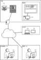
- FIG. 3 is a diagram showing the scope of application of the video generation device.
- FIG. 1 is a block diagram of a video generation device. It is an external view of a machining center. It is a table showing data extraction conditions.
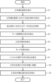
- 3 is a flowchart showing a procedure for setting a tool correction amount. This is an example of a tool correction screen. It is a figure explaining the machine coordinate value of a tool measuring device.
- FIG. 3 is a diagram illustrating setting of workpiece coordinates. It is a figure showing the positional relationship of a tool and a tool measuring instrument. It is a figure explaining setting of tool length.
- FIG. 2 is a diagram showing an example of a conventional video.
- FIG. 2 is a diagram illustrating an example of a video to which the present disclosure is applied.
- FIG. 2 is a hardware configuration diagram of a video generation device.
- the image generation device acquires images of industrial machines installed in a factory and data indicating the state of the industrial machines. Video and data are stored in data loggers, PLCs, internal and external servers, numerical control devices, etc.
- the video generation device 100 acquires already accumulated data and generates a recorded video showing the operation of the industrial machine.
- the recorded video consists of images of industrial machinery and data explaining the state of the industrial machinery.
- the video generation device 100 is applied to information processing devices such as PCs (personal computers), servers, and mobile terminals.
- the video generation device 100 includes a PC used by a factory manager, a server on the cloud, a PC used by an operator of a machine manufacturer or a control machine manufacturer, and a PC used by a factory manager. This applies to, but is not limited to, mobile terminals used.
- the video generated by the video generation device 100 is utilized for management of industrial machinery (maintenance, production management, etc.).
- FIG. 2 is a block diagram of the video generation device 100.
- the video generation device 100 includes a video acquisition section 1 , a data acquisition section 2 , a screen discrimination section 3 , an extraction condition storage section 4 , a data extraction section 5 , and a video generation section 6 .
- the image acquisition unit 1 acquires images of machines and equipment in the factory from data loggers, internal and external servers, PLCs, numerical control devices, and the like.
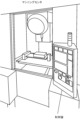
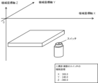
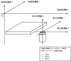
- FIG. 3 shows the appearance of the machining center.
- the machining center of the present disclosure is provided with two cameras. One camera images the workpiece attached to the table, and the other camera images the operation panel. Only the buttons and dials on the control panel may be photographed, and the display screen may be captured. Time information is added to the video acquired by the video acquisition unit 1, and it can be merged with data representing the machine state (described later). Note that in the present disclosure, video includes both moving images and still images.
- Video also includes images in which multiple still images are displayed consecutively. Further, in the present disclosure, an image of the interior of the machining center, an operation screen of the numerical control device, and an operation panel of the numerical control device are displayed side by side, but either the operation panel of the numerical control device or the operation screen of the numerical control device is displayed side by side. You may display only
- the data acquisition unit 2 acquires data regarding numerical control devices and machine tools from data loggers, internal and external servers, PLCs, numerical control devices, and the like.
- the data acquired by the data acquisition unit 2 includes status information of the numerical control device, operation input information, control information of the machine tool, and the like.
- the status information of the numerical control device is set in the internal variables of the numerical control device, and includes the mode of the numerical control device, tool offset amount, alarm, time, number of parts to be machined, modal information, position information (coordinate system), There are various types of signals.
- Operational input information includes input to the touch panel and input using physical buttons, dials, and handles.
- the machine tool control information includes physical quantities necessary for controlling the machine tool, machine tool status information, and the like.
- Control information for machine tools includes power consumption, load on servo motors, and data measured by sensors (temperature and pressure).
- the screen determination unit 3 determines the type of display screen based on the data acquired by the data acquisition unit 2 and the video acquired by the video acquisition unit 1.
- Known image analysis is used to determine the type of display screen based on the video. It may be determined what kind of screen is being displayed by image analysis. Image analysis may be used to determine information such as the button operated by the user, the type and position of the tool, the installation and position of the workpiece, and the start and end of machining.
- the data acquired by the data acquisition unit 2 includes status information of the numerical control device, operation input information of the numerical control device, control information of the machine tool, and the like.
- the status information of the numerical control device includes mode information of the numerical control device.
- the screen determination unit 3 determines the type of display screen based on the mechanical state and operation input of the numerical control device.
- the display screen can be identified by the screen ID.
- the extraction condition storage unit 4 stores data extraction conditions.
- the data to be extracted is determined by the type of display screen and the state of the numerical control device (industrial machine).
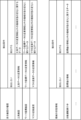
- FIG. 4 shows an example of extraction conditions.
- the upper table in Figure 4 defines the extraction conditions for the display screen type.
- “Tool data change information” is not extracted, and “Tool data change information” is not extracted. It is defined as extracting "data related to changes in machine status other than information”. Since “tool data change information” is displayed on the “tool screen,” only data that cannot be determined from the display screen is extracted.
- “work coordinate screen” it is defined that "change information of work coordinate data” is not extracted, but “data related to machine state changes other than change information of work coordinate data” is extracted. Since “workpiece coordinate data change information” is displayed on the "workpiece coordinate screen,” data that cannot be determined from the display screen is extracted.
- the data extraction section 5 extracts data based on the extraction conditions stored in the extraction condition storage section 4.
- the extracted data includes data that is always displayed in the generated video and data that is displayed only when the data value changes. If the data is to be displayed constantly, read the data periodically. In the case of data that is displayed only when the data value changes, when a change (change) in the data is detected, the extraction conditions are referred to and it is determined whether or not to extract the data.
- the data extraction unit 5 adds a time stamp to the extracted data. The timestamp indicates the time when the data changed (changed).
- the extraction conditions are conditions for excluding information that overlaps with information provided by the display screen.
- the data extraction unit 5 detects data instructing to start setting the tool correction amount, and determines that the tool correction screen has been displayed in accordance with the instruction (step S1).
- FIG. 6 is an example of the tool correction screen.
- the tool compensation screen in Figure 6 displays a list of the tool number, tool shape compensation amount (tool length), wear compensation amount (tool length), tool shape compensation amount (tool diameter), and wear compensation amount (tool diameter). , relative coordinates, absolute coordinates, and mechanical coordinates are displayed. At the bottom of the tool offset screen, a correction amount input button and a delete button are displayed.
- the data extraction unit 5 reads extraction conditions corresponding to the tool correction screen (step S2).
- the data extraction unit 5 searches for changes in data included in the extraction conditions (step S3).
- the data extraction unit 5 detects the setting (change) of the workpiece coordinate system (absolute coordinates) with the switch of the tool measuring device as the origin based on the data acquired by the data acquisition unit 2 (step S4).
- key inputs such as “ ⁇ (upward arrow)”, “ ⁇ (downward arrow)”, “ ⁇ (leftward arrow)”, and “ ⁇ (rightward arrow)” are input, but such input signals Changes in can be determined from the video, so they are not extracted as display data.
- the machine coordinates "X: 300.0", “Y: 240.0”, “Z: -380.0" of the switch of the tool measuring device are set to the workpiece coordinate origin "G55". Since the setting of the workpiece coordinate origin "G55" can be determined from the video, it is not extracted as display data.
- the data extraction unit 5 detects the selection (change) of the tool to be measured (step S5). Data regarding the tool cannot be determined from the tool correction screen shown in FIG. Therefore, data related to tools, such as "tool change: T1 ⁇ T5", is extracted as display data. Note that if a plurality of tools are selected, the processes from step S4 to step S5 are repeated a plurality of times.
- the data extraction unit 5 detects a mode switch (change) from “memory mode” to "handle mode” (step S6).
- "Memory mode” is a mode in which the numerical control device automatically operates according to a program
- "handle mode” is a mode in which the main shaft is moved by operating the handle.
- the mode extraction condition is "always display”.
- the data extraction unit 5 extracts data indicating the mode.
- the data extraction unit 5 detects a change in the operating direction of the handle (step S7).
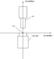
- the tool is placed directly above the tool measurer (see Figure 9). Since the operating direction of the handle cannot be determined from the video, data on the operating direction, such as "HANDLE +Z”, “HANDLE -Z”, “HANDLE +X”, and "HANDLE -X”, is extracted as display data.
- a tool is attached to the tip of the spindle.
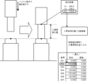
- the tip of the tool comes into contact with the tool measuring device (step S8). Since the switch position of the tool measuring device is set to the work coordinate origin "G55", the value of the Z axis when the work coordinate origin "G55" when the tool contacts the tool measuring device is set as the origin indicates the tool length. In the example of FIG. 10, the value of the Z axis is "110.000".
- the data extraction unit 5 detects the setting (change) of the tool shape correction amount (step S9).
- the tool length correction amount for tool number "002" is set to "110.000".
- the tool length correction amount changes from “0.000" to "110.000", but since this change can be determined from the video, it is not extracted as display data.
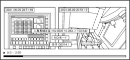
- the video generation unit 6 merges the video acquired by the video acquisition unit 1 and the data extracted by the data extraction unit 5 based on time, and creates a screen that displays changes in the state of the machine as data. Changes in the display screen will be explained with reference to FIGS. 11 and 12.
- FIG. 11 is an example of a video generated by a conventional video generation device 100
- FIG. 12 is an example of a video generated by the video generation device 100 to which the present disclosure is applied.
- data extraction conditions are set at the time when a video is shot, and data that meets the extraction conditions is extracted as display data.
- Display data is saved with a time stamp.
- the video generation device merges video and data using time as a key, and displays the data superimposed on the video. According to the video generation device of the present disclosure, since the number of display data can be suppressed, a display screen with good visibility can be provided.
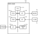
- FIG. 13 is a hardware configuration diagram of the video generation device 100.
- the video generation device 100 includes a CPU 111 that controls the video generation device 100 as a whole, a ROM 112 that records programs and data, and a RAM 113 that temporarily expands data.
- a system program recorded in the ROM 112 is read out through the ROM 112, and the entire video generation apparatus 100 is controlled in accordance with the system program.
- the nonvolatile memory 114 is backed up by, for example, a battery (not shown), so that its storage state is maintained even when the power of the video generation device 100 is turned off.
- the nonvolatile memory 114 stores various data such as programs read from external devices via the interfaces 115, 118, and 119 and user operations input via the input unit 30.
- Video generation device 1 Video acquisition unit 2 Data acquisition unit 3 Screen discrimination unit 4 Extraction condition storage unit 5 Data extraction unit 6 Video generation unit 111 CPU 113 RAM 114 Non-volatile memory
Landscapes
- Physics & Mathematics (AREA)
- General Physics & Mathematics (AREA)
- Engineering & Computer Science (AREA)
- Automation & Control Theory (AREA)
- Numerical Control (AREA)
Priority Applications (2)
| Application Number | Priority Date | Filing Date | Title |
|---|---|---|---|
| PCT/JP2022/020223 WO2023218640A1 (ja) | 2022-05-13 | 2022-05-13 | 映像生成装置、及びコンピュータが読み取り可能な記憶媒体 |
| JP2024520213A JPWO2023218640A1 (enExample) | 2022-05-13 | 2022-05-13 |
Applications Claiming Priority (1)
| Application Number | Priority Date | Filing Date | Title |
|---|---|---|---|
| PCT/JP2022/020223 WO2023218640A1 (ja) | 2022-05-13 | 2022-05-13 | 映像生成装置、及びコンピュータが読み取り可能な記憶媒体 |
Publications (1)
| Publication Number | Publication Date |
|---|---|
| WO2023218640A1 true WO2023218640A1 (ja) | 2023-11-16 |
Family
ID=88730123
Family Applications (1)
| Application Number | Title | Priority Date | Filing Date |
|---|---|---|---|
| PCT/JP2022/020223 Ceased WO2023218640A1 (ja) | 2022-05-13 | 2022-05-13 | 映像生成装置、及びコンピュータが読み取り可能な記憶媒体 |
Country Status (2)
| Country | Link |
|---|---|
| JP (1) | JPWO2023218640A1 (enExample) |
| WO (1) | WO2023218640A1 (enExample) |
Citations (4)
| Publication number | Priority date | Publication date | Assignee | Title |
|---|---|---|---|---|
| JP2005018298A (ja) * | 2003-06-25 | 2005-01-20 | Hitachi Ltd | 監視,操作方法および表示装置 |
| JP2005056098A (ja) * | 2003-08-04 | 2005-03-03 | Digital Electronics Corp | 表示装置 |
| JP2017167867A (ja) * | 2016-03-17 | 2017-09-21 | 株式会社ジェイテクト | 工作機械用管理システム |
| JP2020179487A (ja) * | 2019-04-26 | 2020-11-05 | 株式会社ディスコ | 加工装置 |
-
2022
- 2022-05-13 WO PCT/JP2022/020223 patent/WO2023218640A1/ja not_active Ceased
- 2022-05-13 JP JP2024520213A patent/JPWO2023218640A1/ja active Pending
Patent Citations (4)
| Publication number | Priority date | Publication date | Assignee | Title |
|---|---|---|---|---|
| JP2005018298A (ja) * | 2003-06-25 | 2005-01-20 | Hitachi Ltd | 監視,操作方法および表示装置 |
| JP2005056098A (ja) * | 2003-08-04 | 2005-03-03 | Digital Electronics Corp | 表示装置 |
| JP2017167867A (ja) * | 2016-03-17 | 2017-09-21 | 株式会社ジェイテクト | 工作機械用管理システム |
| JP2020179487A (ja) * | 2019-04-26 | 2020-11-05 | 株式会社ディスコ | 加工装置 |
Also Published As
| Publication number | Publication date |
|---|---|
| JPWO2023218640A1 (enExample) | 2023-11-16 |
Similar Documents
| Publication | Publication Date | Title |
|---|---|---|
| JP6432494B2 (ja) | 監視装置、監視システム、監視プログラムおよび記録媒体 | |
| CN105992976B (zh) | 加工信息管理装置以及工具路径生成装置 | |
| JP6377167B2 (ja) | 工作機械の制御装置 | |
| EP3699709B1 (en) | Servo motor adjusting device and servo motor adjusting method | |
| US20190266296A1 (en) | Machining simulation device of machine tool | |
| TWI559107B (zh) | 監視控制裝置 | |
| CN106462141B (zh) | 机床的控制装置 | |
| KR20190105518A (ko) | 로봇 제어 장치, 기록의 작성 방법 및 프로그램 | |
| JP2019160250A (ja) | 情報処理装置、情報処理方法、プログラム、および機械装置 | |
| JP7668669B2 (ja) | 分析装置、分析システム、およびその制御方法 | |
| WO2023218640A1 (ja) | 映像生成装置、及びコンピュータが読み取り可能な記憶媒体 | |
| JP2009000373A (ja) | ミシンの生産管理装置 | |
| US20180292807A1 (en) | Information processing device | |
| EP4492176A1 (en) | Monitoring data processing device | |
| JP7712373B2 (ja) | 教示装置及びロボットシステム | |
| CN117279737B (zh) | 运行状况显示装置以及计算机可读存储介质 | |
| JP7546502B2 (ja) | 状態診断システム | |
| WO2023218643A1 (ja) | 映像生成装置、及びコンピュータが読み取り可能な記憶媒体 | |
| WO2023218651A1 (ja) | 映像関連情報決定装置、及びコンピュータが読み取り可能な記憶媒体 | |
| JP7646098B1 (ja) | 画面データ作成プログラム、画面データ作成装置、プログラマブル表示システム、プログラマブル表示器及び画面データ作成方法 | |
| WO2023218653A1 (ja) | 映像管理装置、及びコンピュータが読み取り可能な記憶媒体 | |
| EP1746474A1 (en) | Numerical controller with integrated CNC frame and application frame display | |
| KR102902787B1 (ko) | 감시 데이터 처리 장치 | |
| WO2024062541A9 (ja) | 画像生成システム及びコンピュータ読み取り可能な記録媒体 | |
| WO2023218655A1 (ja) | 映像管理装置、及びコンピュータが読み取り可能な記憶媒体 |
Legal Events
| Date | Code | Title | Description |
|---|---|---|---|
| 121 | Ep: the epo has been informed by wipo that ep was designated in this application |
Ref document number: 22941717 Country of ref document: EP Kind code of ref document: A1 |
|
| ENP | Entry into the national phase |
Ref document number: 2024520213 Country of ref document: JP Kind code of ref document: A |
|
| NENP | Non-entry into the national phase |
Ref country code: DE |
|
| 122 | Ep: pct application non-entry in european phase |
Ref document number: 22941717 Country of ref document: EP Kind code of ref document: A1 |