WO2023218639A1 - 空気調和機の室外機 - Google Patents
空気調和機の室外機 Download PDFInfo
- Publication number
- WO2023218639A1 WO2023218639A1 PCT/JP2022/020217 JP2022020217W WO2023218639A1 WO 2023218639 A1 WO2023218639 A1 WO 2023218639A1 JP 2022020217 W JP2022020217 W JP 2022020217W WO 2023218639 A1 WO2023218639 A1 WO 2023218639A1
- Authority
- WO
- WIPO (PCT)
- Prior art keywords
- housing
- panel
- heat exchanger
- casing
- metal
- Prior art date
- Legal status (The legal status is an assumption and is not a legal conclusion. Google has not performed a legal analysis and makes no representation as to the accuracy of the status listed.)
- Ceased
Links
Images







Classifications
-
- F—MECHANICAL ENGINEERING; LIGHTING; HEATING; WEAPONS; BLASTING
- F28—HEAT EXCHANGE IN GENERAL
- F28F—DETAILS OF HEAT-EXCHANGE AND HEAT-TRANSFER APPARATUS, OF GENERAL APPLICATION
- F28F19/00—Preventing the formation of deposits or corrosion, e.g. by using filters or scrapers
-
- F—MECHANICAL ENGINEERING; LIGHTING; HEATING; WEAPONS; BLASTING
- F24—HEATING; RANGES; VENTILATING
- F24F—AIR-CONDITIONING; AIR-HUMIDIFICATION; VENTILATION; USE OF AIR CURRENTS FOR SCREENING
- F24F1/00—Room units for air-conditioning, e.g. separate or self-contained units or units receiving primary air from a central station
- F24F1/06—Separate outdoor units, e.g. outdoor unit to be linked to a separate room comprising a compressor and a heat exchanger
- F24F1/56—Casing or covers of separate outdoor units, e.g. fan guards
-
- F—MECHANICAL ENGINEERING; LIGHTING; HEATING; WEAPONS; BLASTING
- F24—HEATING; RANGES; VENTILATING
- F24F—AIR-CONDITIONING; AIR-HUMIDIFICATION; VENTILATION; USE OF AIR CURRENTS FOR SCREENING
- F24F1/00—Room units for air-conditioning, e.g. separate or self-contained units or units receiving primary air from a central station
- F24F1/06—Separate outdoor units, e.g. outdoor unit to be linked to a separate room comprising a compressor and a heat exchanger
- F24F1/14—Heat exchangers specially adapted for separate outdoor units
- F24F1/16—Arrangement or mounting thereof
-
- F—MECHANICAL ENGINEERING; LIGHTING; HEATING; WEAPONS; BLASTING
- F24—HEATING; RANGES; VENTILATING
- F24F—AIR-CONDITIONING; AIR-HUMIDIFICATION; VENTILATION; USE OF AIR CURRENTS FOR SCREENING
- F24F1/00—Room units for air-conditioning, e.g. separate or self-contained units or units receiving primary air from a central station
- F24F1/06—Separate outdoor units, e.g. outdoor unit to be linked to a separate room comprising a compressor and a heat exchanger
- F24F1/46—Component arrangements in separate outdoor units
-
- F—MECHANICAL ENGINEERING; LIGHTING; HEATING; WEAPONS; BLASTING
- F28—HEAT EXCHANGE IN GENERAL
- F28F—DETAILS OF HEAT-EXCHANGE AND HEAT-TRANSFER APPARATUS, OF GENERAL APPLICATION
- F28F21/00—Constructions of heat-exchange apparatus characterised by the selection of particular materials
- F28F21/06—Constructions of heat-exchange apparatus characterised by the selection of particular materials of plastics material
-
- F—MECHANICAL ENGINEERING; LIGHTING; HEATING; WEAPONS; BLASTING
- F28—HEAT EXCHANGE IN GENERAL
- F28D—HEAT-EXCHANGE APPARATUS, NOT PROVIDED FOR IN ANOTHER SUBCLASS, IN WHICH THE HEAT-EXCHANGE MEDIA DO NOT COME INTO DIRECT CONTACT
- F28D21/00—Heat-exchange apparatus not covered by any of the groups F28D1/00 - F28D20/00
- F28D2021/0019—Other heat exchangers for particular applications; Heat exchange systems not otherwise provided for
- F28D2021/0068—Other heat exchangers for particular applications; Heat exchange systems not otherwise provided for for refrigerant cycles
- F28D2021/007—Condensers
-
- F—MECHANICAL ENGINEERING; LIGHTING; HEATING; WEAPONS; BLASTING
- F28—HEAT EXCHANGE IN GENERAL
- F28F—DETAILS OF HEAT-EXCHANGE AND HEAT-TRANSFER APPARATUS, OF GENERAL APPLICATION
- F28F2280/00—Mounting arrangements; Arrangements for facilitating assembling or disassembling of heat exchanger parts
Definitions
- the present disclosure relates to an outdoor unit of an air conditioner that includes a housing and a heat exchanger.
- a conventional outdoor unit of an air conditioner one is known that includes a box-shaped casing and a heat exchanger disposed within the casing, and the heat exchanger and the casing are each made of different metals. .
- the metal types of the heat exchanger and the housing are selected depending on the required characteristics. For example, aluminum is generally used for heat exchangers that require high thermal conductivity, and iron is generally used for casings that require strength.
- heat exchanger and the casing which are dissimilar metals
- dissimilar metal contact corrosion will occur in the metal with a lower natural potential.
- catalytic corrosion of dissimilar metals will be simply referred to as corrosion.
- a means for preventing corrosion there is known a means for indirectly connecting the heat exchanger and the casing via a non-conductive member such as resin.
- the heat exchanger and the casing are electrically insulated by the non-conductive member, so a parasitic capacitance is generated between the heat exchanger and the casing. Then, there is a problem in that electromagnetic noise generated from an electronic board, a compressor, etc. disposed within the housing causes a voltage change in the parasitic capacitance, and this voltage change further generates electromagnetic noise.
- an air supply port is formed on the back of the casing to allow outdoor air to flow in, and the heat exchanger is located at a position facing the air supply port to exchange heat with the outdoor air. It is located in Electromagnetic noise is radiated from between the heat exchanger and the housing to the outside of the housing through the air supply port.
- Patent Document 1 discloses a technique in which a conductive connecting member is interposed between the heat exchanger and the casing.
- the connection members include a first connection part that is made of the same kind of metal as that used for the heat exchanger and directly contacts the heat exchanger, and a first connection part that is made of the same kind of metal as that used for the casing and is in direct contact with the heat exchanger. and a second connection portion in direct contact with the second connection portion.
- an insulating layer is provided between the first connection part and the second connection part to electrically insulate the first connection part and the second connection part.
- Patent Document 1 With the technology disclosed in Patent Document 1, the structure becomes complicated due to the use of multiple types of metals for the connection member, the provision of an insulating layer, and the use of a waterproof covering member, which increases manufacturing man-hours. There are problems such as an increase in the number of parts and an increase in the number of parts.
- the present disclosure has been made in view of the above, and aims to provide an outdoor unit of an air conditioner that has a simple structure and can prevent corrosion and reduce electromagnetic noise.
- an outdoor unit of an air conditioner includes a box-shaped casing made of a first metal, and a box-shaped casing made of a first metal, at least a part of which is made of the first metal.
- a heat exchanger is formed of a second metal that has a different natural potential from that of the heat exchanger, and is placed inside the housing and fixed to the housing via a non-conductive member. and a conductive member. The conductive member is fixed to the housing and electrically connected to the housing, and is also electrically connected to the heat exchanger.
- the outdoor unit of the air conditioner according to the present disclosure has a simple structure and has the effect of being able to prevent corrosion and reduce electromagnetic noise at the same time.
- FIG. 2 is a front view of the outdoor unit of the air conditioner according to Embodiment 1, with the front panel of the casing removed.
- An exploded perspective view showing an electronic board box and an interface panel in Embodiment 1 A perspective view showing an assembled state of the electronic board box and interface panel shown in FIG. 3
- Right side view showing the outdoor unit of the air conditioner in Embodiment 1 A cross-sectional view along the VI-VI line shown in Figure 2
- Front view showing the heat exchanger in Embodiment 1 Enlarged view of the main parts of the heat exchanger shown in Figure 8 FIG.
- FIG. 2 is a plan view showing a conductive member in Embodiment 1, and a diagram showing a first conductive member.
- FIG. 2 is a plan view showing the conductive member in Embodiment 1, and a diagram showing a second conductive member.
- FIG. 2 is a plan view showing the outdoor unit of the air conditioner according to Embodiment 1, with the top panel of the casing removed and a conductive member attached to the casing.
- a circuit diagram showing an equivalent circuit of a path through which current that causes electromagnetic noise is transmitted when the outdoor unit of the air conditioner according to Embodiment 1 does not include a conductive member.
- FIG. 2 is a rear view of the outdoor unit of the air conditioner according to Embodiment 1, showing locations where electromagnetic noise occurs when no conductive member is provided.
- a circuit diagram showing an equivalent circuit of a path through which current that causes electromagnetic noise is transmitted when the heat exchanger and the casing are brought into direct contact without using an insulating member.
- FIG. 1 is an exploded perspective view schematically showing an outdoor unit 1 of an air conditioner according to a first embodiment.
- an outdoor unit 1 of an air conditioner includes a housing 2, a plurality of conductive members 3, a partition panel 4, a blower 5, a heat exchanger 6, and a plurality of insulating members 7. , a compressor 8, and an electronic board box 9.
- the outdoor unit 1 of the air conditioner may be simply referred to as the outdoor unit 1.
- the depth direction of the outdoor unit 1 is referred to as the X-axis direction
- the height direction of the outdoor unit 1 is referred to as the Y-axis direction
- the width direction of the outdoor unit 1 is referred to as the Z-axis direction.
- the + direction in the X-axis direction is defined as the front
- the - direction in the X-axis direction is defined as the rear.
- the + direction in the X-axis direction is the direction from the - side to the + side of the X-axis
- the - direction in the X-axis direction is the direction from the + side to the - side of the X-axis.
- the + direction in the Y-axis direction is defined as the upper direction
- the - direction in the Y-axis direction is defined as the lower direction.
- the + direction in the Y-axis direction is the direction from the - side to the + side of the Y-axis
- the - direction in the Y-axis direction is the direction from the + side to the - side of the Y-axis.
- the + direction in the Z-axis direction is defined as the right direction
- the - direction in the Z-axis direction is defined as the left direction.
- the + direction in the Z-axis direction is the direction from the - side to the + side of the Z-axis
- the - direction in the Z-axis direction is the direction from the + side to the - side of the Z-axis.
- the + direction in the X-axis direction in which the airflow generated by the blower 5 of the outdoor unit 1 is discharged to the outside is defined as the front
- the side opposite to the front is defined as the back.
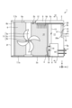
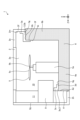
- FIG. 2 is a front view of the outdoor unit 1 of the air conditioner according to the first embodiment, with the front panel 2e of the casing 2 removed.
- the heat exchanger 6 is shown with dot hatching for ease of understanding.
- the housing 2 is a box-shaped member that serves as an outer shell of the outdoor unit 1.
- the housing 2 is made of a first metal.
- the first metal is preferably a metal with high strength.
- the first metal is, for example, iron or an iron alloy.
- the housing 2 includes a housing floor panel 2a, a housing top panel 2b, a first connecting panel 2c, and a second connecting panel 2d.
- the housing floor panel 2a constitutes the bottom surface of the outer shell of the outdoor unit 1.
- the casing floor panel 2a has a rectangular shape in plan view with four rounded corners.
- the housing top panel 2b is arranged above the housing floor panel 2a and away from the housing floor panel 2a.
- the housing top panel 2b constitutes the ceiling surface of the outer shell of the outdoor unit 1.
- the plan view shape of the housing top panel 2b is the same as the plan view shape of the housing floor panel 2a.
- the first connection panel 2c and the second connection panel 2d connect the housing floor panel 2a and the housing top panel 2b.
- the first connection panel 2c has an L-shape in plan view.
- the first connection panel 2c includes a housing front panel 2e extending along the Z-axis direction, and a housing front panel 2e extending rearward from the left edge, which is one edge along the Z-axis direction of the housing front panel 2e. It has a body side panel 2f.
- the housing front panel 2e connects the front edge of the housing floor panel 2a and the front edge of the housing top panel 2b.
- the housing front panel 2e constitutes the front surface of the outer shell of the outdoor unit 1.
- An exhaust port 2j is formed in the housing front panel 2e.
- the exhaust port 2j is an opening for discharging the airflow generated by the blower 5 to the outside of the fan chamber 10, which will be described later.
- the housing side panel 2f connects the left edge of the housing floor panel 2a and the left edge of the housing top panel 2b.
- the housing side panel 2f constitutes the left side of the outer shell of the outdoor unit 1.
- the plan view shape of the second connection panel 2d is L-shaped.
- the second connection panel 2d extends leftward from the housing side panel 2g extending along the X-axis direction and the rear edge that is one edge along the X-axis direction of the housing side panel 2g.
- the housing has a rear panel 2h.
- the housing side panel 2g connects the right edge of the housing floor panel 2a and the right edge of the housing top panel 2b.
- the housing side panel 2g constitutes the right side of the outer shell of the outdoor unit 1.
- the housing back panel 2h connects a part of the rear edge of the housing floor panel 2a and a part of the rear edge of the housing top panel 2b.
- the housing back panel 2h constitutes a part of the back surface of the outer shell of the outdoor unit 1.
- the left edge of the housing back panel 2h and the rear edge of the housing side panel 2f are separated from each other.
- An air supply port 2i for introducing outdoor air is formed between the left edge of the housing back panel 2h and the rear edge of the housing side panel 2f.
- the air supply port 2i is an opening that allows air outside the housing 2 to flow into a fan chamber 10, which will be described later.
- the air supply port 2i is surrounded by a housing floor panel 2a, a housing top panel 2b, a housing back panel 2h, and a housing side panel 2f.
- the conductive member 3 is a member disposed within the casing 2.
- the conductive member 3 is made of a non-metal that is conductive to metal.
- the material of the conductive member 3 is, for example, a composite material in which a conductor such as carbon fiber is kneaded into an insulating plastic, or a composite material in which a thin film of a conductor is formed on the surface of an insulating plastic.
- An example of such a composite material is carbon graphite.
- the conductive member 3 is fixed to and electrically connected to the casing 2 and is also electrically connected to the heat exchanger 6 .
- the casing 2 and the heat exchanger 6 are electrically connected via the conductive member 3.
- electrically connected between the metal member and the conductive member 3 refers to a state in which the metal member and the conductive member 3 are in direct contact and conduction, as well as a state in which the metal member and the conductive member 3 are electrically conductive. This also includes a state in which the sexual member 3 is electrically connected through a gap.
- the conductive member 3 is in contact with the housing 2 and the heat exchanger 6 in this embodiment.
- each panel of the housing 2 is coated with paint or the like and has a high electrical resistance, for example, masking some or all of the joints in advance or tightening the screws using serrated screws.
- the electrical resistance on the surface of each panel can be lowered by removing the paint when tightening.
- the number of conductive members 3 may be singular or plural, but in this embodiment, it is two.
- one conductive member 3 will be referred to as a first conductive member 3a
- the other conductive member 3 will be referred to as a second conductive member 3b.
- the partition panel 4 is a metal member that partitions the inside of the housing 2 into a fan chamber 10 and an electrical room 11.
- the partition panel 4 becomes a part of the housing 2.
- the fan chamber 10 and the electrical chamber 11 are formed side by side in the Z-axis direction.
- the partition panel 4 extends in the Y-axis direction from the housing floor panel 2a to the electronic board box 9.
- the partition panel 4 extends in the X-axis direction from the housing front panel 2e to the housing back panel 2h shown in FIG.
- the housing 2 and the partition panel 4 shown in FIG. 1 are made of the same type of first metal.
- the portions where the housing 2 and the partition panel 4 come into contact with each other are joined by welding, screws, or the like. If the surface of each panel of the casing 2 is coated with paint, etc. and the electrical resistance of the surface of each panel is high, for example, masking some or all of the joints in advance or using serration screws to tighten the The electrical resistance on the surface of each panel can be lowered by removing the paint when tightening.
- the blower 5 is a device that is placed in the fan room 10 and generates airflow.
- the blower 5 includes a support 5a rising from the housing floor panel 2a, a fan motor 5b attached to the support 5a, and a propeller fan 5c attached to the rotating shaft of the fan motor 5b to rotate as the fan motor 5b rotates. It has The upper end of the support column 5a is fixed to the housing top panel 2b. The lower end of the support column 5a is fixed to the housing floor panel 2a.
- the fan motor 5b is electrically connected to an electronic board 9c, which will be described later, via a fan drive wire 12. The fan motor 5b rotates when receiving a drive signal output from the electronic board 9c via the fan drive wire 12.
- the heat exchanger 6 is a member disposed in the fan room 10 to exchange heat between the refrigerant and outdoor air. Outdoor air to be taken into the blower 5 passes through the heat exchanger 6 .
- the heat exchanger 6 is, for example, a parallel flow type heat exchanger.
- the heat exchanger 6 is disposed within the casing 2 and fixed to the casing 2 via an insulating member 7 that is a non-conductive member. At least a portion of the heat exchanger 6 is formed of a second metal that has a different natural potential from the first metal.
- the second metal is preferably a metal with high thermal conductivity.
- the second metal is, for example, aluminum or an aluminum alloy.
- the natural potential of the first metal is higher than the natural potential of the second metal.
- the shape of the heat exchanger 6 in plan view is L-shaped.
- the heat exchanger 6 has a first heat exchange section 6a extending along the Z-axis direction and a second heat exchange section 6b extending along the X-axis direction.
- the second heat exchange section 6b extends forward from the left end, which is one end along the Z-axis direction of the first heat exchange section 6a.
- the first heat exchange section 6a is arranged behind the blower 5.
- the second heat exchange section 6b is arranged on the left side of the blower 5 when viewed from the front of the outdoor unit 1.
- the heat exchanger 6 and the blower 5 are either spaced from each other and electrically insulated, or are arranged and electrically insulated via an insulating member (not shown).
- the heat exchanger 6, the first connection panel 2c, and the second connection panel 2d are arranged at intervals and electrically insulated from each other, or are arranged via an insulating member (not shown). electrically isolated. As shown in FIG. 2, the upper end of the heat exchanger 6 is fixed to the housing top panel 2b via an insulating member 7. A lower end portion of the heat exchanger 6 is fixed to the housing floor panel 2a via an insulating member 7. The heat exchanger 6, the housing top panel 2b, and the housing floor panel 2a are electrically insulated. The heat exchanger 6 is arranged without directly contacting metal members such as the housing 2 and the blower 5 arranged around the heat exchanger 6.
- the two insulating members 7 shown in FIG. 1 are made of an electrically insulating material such as resin.
- the insulating member 7 provided at the lower end of the heat exchanger 6 will be referred to as a first insulating member 7a
- the insulating member 7 provided at the upper end of the heat exchanger 6 will be referred to as a first insulating member 7a.
- the member 7 is referred to as a second insulating member 7b.
- the entire bottom and top surfaces of the heat exchanger 6 are covered by using the first insulating member 7a and the second insulating member 7b, which have the same planar shape and the same size as the heat exchanger 6.
- the heat exchanger 6 and the housing 2 are electrically insulated by covering them, this is not intended to limit the electrical insulating means for both members.
- a configuration may be adopted in which several stands made of electrically insulating material are provided on the bottom of the heat exchanger 6, and the stands are interposed between the heat exchanger 6 and the housing floor panel 2a. Good too. With this configuration, the heat exchanger 6 and the housing floor panel 2a are separated from each other in the Y-axis direction, so that the heat exchanger 6 and the housing floor panel 2a can be electrically insulated.
- the compressor 8 is a device that is placed in the electrical room 11 and compresses the refrigerant flowing inside the heat exchanger 6.
- the compressor 8 is arranged on the housing floor panel 2a in the lower space of the electrical room 11.
- the compressor 8 is fixed to the housing floor panel 2a with screws or the like.
- the electronic board box 9 is a member that accommodates an electronic board 9c such as a control board necessary for operating the outdoor unit 1.
- the electronic board box 9 is formed into a hollow rectangular parallelepiped shape.
- the electronic board box 9 is fixed to the upper end of the partition panel 4 and is disposed astride the fan room 10 and the electrical room 11.
- a heat sink 9d extending downward is attached to a portion of the electronic board box 9 located in the fan chamber 10.
- the heat sink 9d is exposed to the fan chamber 10.
- the heat sink 9d is cooled by the airflow generated by the blower 5.
- a portion of the electronic board box 9 located in the electrical room 11 is located above the compressor 8.
- a compressor drive electric wire 13 is connected to a portion of the electronic board 9c located in the electrical room 11.
- the compressor 8 is electrically connected to the electronic board 9c via a compressor drive wire 13.
- the compressor 8 is driven when it receives a drive signal output from the electronic board 9c via the compressor drive wire 13.
- the electrical room 11 is surrounded by a housing floor panel 2a, a partition panel 4, a housing side panel 2g, an electronic board box 9, a housing front panel 2e, and a housing back panel 2h shown in FIG.
- the housing 2 has a waterproof structure that prevents moisture such as rainwater from entering from outside.
- a stop valve 17 is provided at the lower part of the outer surface of the housing side panel 2g. The stop valve 17 serves as a terminal for connecting a refrigerant pipe connected to an indoor unit (not shown).
- the compressor 8 and the stop valve 17 are connected to each other via a plurality of refrigerant pipes 18.
- the compressor 8 and the heat exchanger 6 are connected to each other via a plurality of refrigerant pipes 18.
- a connecting portion 19 between the heat exchanger 6 and the refrigerant pipe 18 is arranged in an electrical room 11 having a waterproof structure.
- the connecting portion 19 may be waterproofed by wrapping it with waterproof tape or the like.
- the refrigerant pipe 18 is connected to a valve device such as a four-way valve that changes the direction in which the refrigerant flows, and an expansion valve that expands the refrigerant to a predetermined pressure.
- a valve device such as a four-way valve that changes the direction in which the refrigerant flows, and an expansion valve that expands the refrigerant to a predetermined pressure.
- the connection form of the refrigerant piping 18 is not limited to the illustrated example.
- An interface panel 20 is installed in the upper space of the electrical room 11.
- the interface panel 20 is fixed to the inner surface of the housing side panel 2g and the lower surface of the electronic board box 9, respectively.
- a terminal block 21 is installed on the interface panel 20.
- An external AC power line 14 and an internal power line 15 are connected to the terminal block 21 .
- External AC power line 14 is electrically connected to internal power line 15 via terminal block 21 .
- Internal power line 15 is electrically connected to electronic board 9c. Power to the electronic board 9c is supplied via the external AC power line 14, the terminal block 21, and the internal power line 15.
- the voltage of the power supplied to the electronic board 9c is, for example, single-phase 200V, but is not limited to this voltage.
- the interface panel 20 is made of the same first metal as the case side panel 2g. Therefore, the interface panel 20 is joined to the housing side panel 2g with low electrical resistance.
- the interface panel 20 is connected to the signal ground of the electronic board 9c.
- the interface panel 20 has a ground connection point 20e to which the ground wire 16 is connected.
- Interface panel 20 is grounded via ground connection point 20e and ground wire 16.
- the casing 2 joined to the interface panel 20 and the partition panel 4 joined to the casing 2 are grounded via a ground connection point 20e and a ground wire 16.
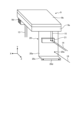
- FIG. 3 is an exploded perspective view showing the electronic board box 9 and the interface panel 20 in the first embodiment.
- FIG. 4 is a perspective view showing a state in which the electronic board box 9 and the interface panel 20 shown in FIG. 3 are assembled.
- the electronic board box 9 includes a box-shaped lower box 9a that opens upward, an upper lid 9b that covers the upper opening of the lower box 9a, an electronic board 9c, and a heat sink 9d. There is.
- the electronic board 9c is placed in the lower box 9a and fixed to the lower box 9a.
- the electronic board 9c has an internal power line 15 connected to the terminal block 21 and a compressor drive electric wire 13 connected to the compressor 8.
- the electronic board 9c includes a heating element, a fan motor 5b, and various power lines for operating other drive devices.
- the heat sink 9d is fixed to the electronic board 9c while being in close contact with the electronic board 9c.
- the heat sink 9d plays a role of cooling the heat generating elements of the electronic board 9c.
- the heating element is, for example, a power semiconductor represented by an IGBT (Insulated Gate Bipolar Transistor).
- the electronic board 9c to which the heat sink 9d is fixed is inserted into the lower box 9a from the opening at the top of the lower box 9a. As shown in FIGS. 3 and 4, part or all of the heat sink 9d is exposed to the outside of the lower box 9a through a hole 9e formed in the bottom wall of the lower box 9a.
- the lower box 9a and upper lid 9b shown in FIG. 3 are made of, for example, rubber, resin, metal such as iron, or a combination thereof.
- the electronic board 9c is surrounded by metal, so that electromagnetic noise generated from the electronic board 9c is not transmitted to the outside of the electronic board box 9. Radiation can be suppressed.
- moisture such as rainwater scattered in the fan chamber 10 may enter the electronic board box 9 and the electrical chamber 11 through the hole 9e formed in the bottom wall of the lower box 9a. Therefore, in practice, measures such as devising the shape of the hole 9e and the shape of the lower box 9a and adding new waterproof structures are taken to prevent moisture from entering the electronic board box. 9 and the electrical room 11 are ensured to be waterproof.
- the interface panel 20 has an interface vertical wall 20a, an upper joint flange portion 20b, an interface horizontal wall 20c, and a lower joint flange portion 20d.
- the interface vertical wall 20a is a vertical wall extending along the Y-axis direction.
- the upper joint flange portion 20b extends horizontally in the Z-axis direction from the upper end of the interface vertical wall 20a.
- the upper joining flange portion 20b is joined to the lower surface of the bottom wall of the lower box 9a.
- the interface horizontal wall 20c extends horizontally in the Z-axis direction from the lower end of the interface vertical wall 20a.
- the lower joining flange portion 20d extends downward in the Y-axis direction from the tip of the interface side wall 20c.
- the lower joining flange portion 20d is joined to the inner surface of the housing side panel 2g shown in FIG.
- the interface panel 20 is fixed to the housing side panel 2g at the lower joint flange portion 20d and is electrically connected to the housing side panel 2g.
- the interface panel 20 is fixed to the housing side panel 2g and the lower box 9a, respectively.
- FIG. 5 is a right side view showing the outdoor unit 1 of the air conditioner according to the first embodiment.
- An opening 2k that communicates the inside and outside of the housing 2 is formed in the housing side panel 2g.
- An interface cover 22 is removably attached to the housing side panel 2g.
- the interface cover 22 can be opened and closed by attaching and detaching it.
- the interface cover 22 covers the opening 2k when closed. When the interface cover 22 is open, the opening 2k is opened.
- the interface panel 20 and terminal block 21 installed in the electrical room 11 are visible and accessible through the opening 2k. Connection work for various power lines can be performed by opening the interface cover 22 and passing through the opening 2k.
- the interface cover 22 plays the role of preventing moisture such as rainwater from entering the electrical room 11 while ensuring ventilation between the electrical room 11 and the outside of the casing 2.
- the interface cover 22 is made of resin, metal such as iron, or a combination thereof. If the interface cover 22 is made of metal such as iron and is bonded to the housing side panel 2g with low electrical resistance, the opening 2k can be closed by the interface cover 22, and the housing can be removed from the opening 2k. 2. Emission of electromagnetic noise to the outside can be suppressed.
- the interface cover 22 has communication holes for the purpose of ensuring ventilation between the electrical room 11 and the outside of the casing 2 and for allowing power lines to enter and exit the electrical room 11 and the outside of the casing 2. is formed.
- Waterproofing means is provided in the communication hole to prevent moisture such as rainwater from entering the electrical room 11.
- a waterproofing means for example, there are means such as filling the gaps between the communication holes with sponge or making the communication holes have a shutter structure.
- FIG. 6 is a cross-sectional view taken along line VI-VI shown in FIG. In FIG. 6, only the housing 2 is hatched for ease of understanding.
- the partition panel 4 has a first partition part 4a and a second partition part 4b continuous to the rear end of the first partition part 4a.
- An introduction hole 4c for introducing the end of the heat exchanger 6 in the Z-axis direction into the electrical room 11 is formed in the second partition portion 4b.
- the heat exchanger 6 and the second partition portion 4b are formed of different metals. In order to avoid contact between dissimilar metals, it is preferable to interpose a resin material between the heat exchanger 6 and the second partition portion 4b, for example.
- FIG. 7 is a perspective view schematically showing the heat exchanger 6 in the first embodiment.
- FIG. 8 is a front view showing the heat exchanger 6 in the first embodiment.
- FIG. 9 is an enlarged view of the main parts of the heat exchanger 6 shown in FIG. 8.
- the heat exchanger 6 is a parallel flow heat exchanger in this embodiment. As shown in FIG. 8, the heat exchanger 6 includes two headers 6c and 6d, a plurality of refrigerant conduits 6e, and a plurality of fins 6f.
- the two headers 6c and 6d are both hollow metal members. Each header 6c, 6d extends along the Y-axis direction. As shown in FIG. 7, the two headers 6c and 6d are arranged apart from each other in the Z-axis direction and shifted from each other in the X-axis direction.
- the header 6c is provided at the front end of the second heat exchange section 6b.
- the header 6d is provided at the right end of the first heat exchange section 6a.
- a refrigerant pipe 18 is connected to the header 6d.
- Each refrigerant conduit 6e shown in FIG. 8 is a hollow metal member.
- Each refrigerant conduit 6e is, for example, a flat tube.
- the plurality of refrigerant conduits 6e are arranged at intervals from each other in the Y-axis direction.
- Each of the refrigerant conduits 6e extends from one header 6c toward the other header 6d.
- the extending direction of each refrigerant conduit 6e is perpendicular to the Y-axis direction.
- One end of each refrigerant conduit 6e in the extending direction is connected to one header 6c, and the other end of each refrigerant conduit 6e in the extending direction is connected to the other header 6d.
- Each refrigerant conduit 6e communicates one header 6c with the other header 6d.
- the fin 6f is a metal plate-like member.
- the fins 6f are arranged between adjacent refrigerant conduits 6e.
- the shape of the fin 6f is not particularly limited, in this embodiment, it is a wave-like shape that projects alternately upward and downward. That is, the fins 6f are corrugated fins in this embodiment. As shown in FIG. 9, the fins 6f are in contact with each of the adjacent refrigerant conduits 6e and are joined by welding or the like.
- a refrigerant flows inside the headers 6c and 6d and inside the refrigerant conduit 6e shown in FIG.
- One of the two headers 6c and 6d serves to distribute refrigerant to each of the plurality of refrigerant conduits 6e.
- the other of the two headers 6c and 6d plays a role of merging the refrigerants flowing out from each of the plurality of refrigerant conduits 6e.
- the refrigerant conduit 6e plays the role of exchanging heat between the refrigerant and outdoor air. That is, heat exchange is performed between the refrigerant flowing inside the refrigerant conduit 6e and the outdoor air flowing around the refrigerant conduit 6e.
- the fins 6f play a role of promoting heat exchange between the refrigerant and outdoor air.
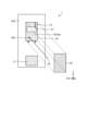
- FIG. 10 is a plan view showing the conductive member 3 in the first embodiment, and is a diagram showing the first conductive member 3a.
- FIG. 11 is a plan view showing the conductive member 3 in the first embodiment, and is a diagram showing the second conductive member 3b.
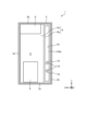
- FIG. 12 is a plan view showing the outdoor unit 1 of the air conditioner according to the first embodiment, with the top panel 2b of the casing 2 removed and the conductive member 3 attached to the casing 2. It is a figure showing the attached state.
- FIG. 10 is a plan view showing the conductive member 3 in the first embodiment, and is a diagram showing the first conductive member 3a.
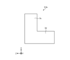
- FIG. 11 is a plan view showing the conductive member 3 in the first embodiment, and is a diagram showing the second conductive member 3b.
- FIG. 12 is a plan view showing the outdoor unit 1 of the air conditioner according to the first embodiment, with the top panel 2b of the casing 2 removed and the conductive member 3 attached to the casing 2. It is a figure showing the attached
- the heat exchanger 6 is shown in direct contact with the partition panel 4 of the housing 2, the side panel 2f of the housing, etc., but in reality, the heat exchanger 6 is in direct contact with the partition panel 4 of the housing 2, the side panel 2f of the housing, etc. Placed without direct contact with metal members. In FIG. 12, the heat exchanger 6 is shown with dot hatching for ease of understanding.
- the shape of the first conductive member 3a is not particularly limited, but is L-shaped in this embodiment.
- the first conductive member 3a has a first plate portion 3c and a second plate portion 3d.
- the first conductive member 3a shown in FIG. 12 electrically connects the partition panel 4 and the first heat exchange section 6a.
- the first conductive member 3a is arranged in the fan chamber 10.
- the first conductive member 3a is arranged at an inner corner formed by the partition panel 4 and the first heat exchange section 6a.
- the first conductive member 3a is arranged on the left side of the partition panel 4.
- the first conductive member 3a is arranged in front of the first heat exchange section 6a.
- the first conductive member 3a is fixed to and electrically connected to the partition panel 4 that is part of the housing 2, and is also electrically connected to the first heat exchange section 6a. There is.
- the first plate portion 3c extends along the X-axis direction.
- the first plate portion 3c is in contact with a side surface 4d of the partition panel 4 facing the fan chamber 10.
- the side surface 4d is a plane extending in the X-axis direction and the Y-axis direction.
- the first plate portion 3c is fixed to the partition panel 4.
- the second plate portion 3d extends along the Z-axis direction.
- the second plate portion 3d extends leftward from the rear end portion of the first plate portion 3c, which is one end along the Z-axis direction.
- the second plate portion 3d is in contact with a front surface 6g of the first heat exchange portion 6a facing the fan chamber 10.
- the front surface 6g is a plane extending in the Z-axis direction and the Y-axis direction.
- the shape of the second conductive member 3b is not particularly limited, but is crank-shaped in this embodiment.
- the second conductive member 3b has a fixing part 3e, a plate part 3f, and a connecting part 3g that connects the fixing part 3e and the plate part 3f.
- the second conductive member 3b shown in FIG. 12 electrically connects the housing side panel 2f and the second heat exchange section 6b.
- the second conductive member 3b is arranged in the fan chamber 10.
- the second conductive member 3b is arranged at an inner corner formed by the housing side panel 2f and the second heat exchange section 6b.
- the second conductive member 3b is arranged on the right side of the housing side panel 2f.
- the second conductive member 3b is arranged from the front to the left of the second heat exchange section 6b.
- the second conductive member 3b is fixed to and electrically connected to the housing side panel 2f, and is also electrically connected to the second heat exchange section 6b.
- the fixed portion 3e extends along the X-axis direction.
- the fixing portion 3e is in contact with an inner surface 2m of the housing side panel 2f facing the fan chamber 10.
- the inner surface 2m is a plane extending in the X-axis direction and the Y-axis direction.
- the fixing portion 3e is fixed to the housing side panel 2f.
- the connecting portion 3g extends rightward from the rear end portion of the fixed portion 3e, which is one end along the X-axis direction.
- the connecting portion 3g extends along the Z-axis direction.
- the connecting portion 3g is in contact with a front surface 6h of the second heat exchange portion 6b facing the fan chamber 10.
- the front surface 6h is a plane extending in the Z-axis direction and the Y-axis direction.
- the plate portion 3f extends rearward from the right end, which is one end along the Z-axis direction of the connecting portion 3g.
- the plate portion 3f extends along the X-axis direction.
- the plate portion 3f is in contact with a side surface 6i of the second heat exchange portion 6b facing the fan chamber 10.
- the side surface 6i is a plane extending in the X-axis direction and the Y-axis direction.
- the side surface 6i extends rearward toward the front surface 6g from the right end, which is one end along the Z-axis direction, of the front surface 6h.
- the conductive member 3 is fixed to the housing side panel 2f or the partition panel 4 and is electrically connected to the housing 2, but the conductive member 3 is fixed to the housing side panel 2f or the partition panel 4 and is electrically connected to the housing 2. , the housing front panel 2e, the housing rear panel 2h, the housing side panels 2f and 2g, and the partition panel 4.
- the size of the conductive member 3 is preferably such that the electrical connection between the casing 2 and the heat exchanger 6 can be maintained even when the outdoor unit 1 vibrates during operation.
- the electronic board 9c when power is supplied to the electronic board 9c from the external AC power line 14 via the internal power line 15, the electronic board 9c enters a standby state.
- the electronic board 9c receives a command signal to start operation from the indoor unit via a communication signal line (not shown) between the indoor unit and the outdoor unit 1, the electronic board 9c starts the operation of the outdoor unit 1.
- the electronic board 9c outputs a drive signal to the fan motor 5b through the fan drive wire 12 to drive the fan motor 5b.
- the electronic board 9c outputs another drive signal to the compressor 8 through the compressor drive electric wire 13 to drive the compressor 8.
- a rectangular wave pulse generated by switching of a power semiconductor is generally used as a drive signal output by the electronic board 9c.
- the drive signal includes high frequency components that are not originally necessary to drive the AC motors of the compressor 8 and the fan motor 5b, such as switching noise of the power semiconductor and harmonic components of the rectangular wave pulse.
- high frequency components become an electromagnetic noise source and become a cause of electromagnetic noise being radiated to the outside of the housing 2 through a transmission path described later.
- FIG. 13 is a schematic diagram showing the transmission path of electromagnetic noise as an electric circuit in the outdoor unit 1 of the air conditioner according to the first embodiment.
- the heat exchanger 6 is shown with dot hatching for ease of understanding.
- electromagnetic noise generated on the electronic board 9c is transmitted to the motor winding 8a and the compressor via the three-phase motor winding neutral point 8d. It is transmitted to the casing of the compressor 8 through the parasitic capacitance 8b existing between the casing of the compressor 8 and the casing of the compressor 8.
- a part of the electromagnetic noise transmitted to the housing of the compressor 8 is transmitted to the housing floor panel 2a and then returned to the electronic board 9c.
- the characteristics of the parasitic impedance component of the heat exchanger 6 differ depending on the structure of the heat exchanger 6.
- the heat exchanger 6 is a parallel flow type heat exchanger equipped with fins 6f and flat refrigerant conduits 6e shown in FIG. 8
- the parasitic inductance of the heat exchanger 6 is An equivalent circuit in which 23 are combined as shown in FIG. 13 is shown as an example.
- the parasitic impedance components such as the parasitic inductance 23 of the heat exchanger 6 exist in a complex manner as a distributed constant circuit as shown in FIG.
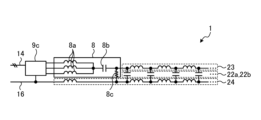
- FIG. 14 is a circuit diagram showing an equivalent circuit of a path through which a current causing electromagnetic noise is transmitted when the outdoor unit 1 of the air conditioner according to the first embodiment does not include the conductive member 3.
- a voltage change occurs in the parasitic capacitances 22a and 22b due to resonance.
- FIG. 15 is a rear view of the outdoor unit 1 of the air conditioner according to the first embodiment, showing locations where electromagnetic noise occurs when the conductive member 3 is not provided.
- the heat exchanger 6 is hatched with dots for easy understanding. Gaps G1, G2, G3, and G4 are formed between the heat exchanger 6 and each panel of the housing 2 to ensure electrical insulation.
- the respective positions of gaps G1, G2, G3, and G4 are surrounded by broken lines.
- FIG. 15 shows that there are no gaps G1, G2, G3, and G4 in a part of the space between the heat exchanger 6 and the housing 2, in reality, the gaps G1, G2, G3, and G4 extend so as to surround the four sides of the heat exchanger 6.
- gaps G1, G2, G3, and G4 become locations where electromagnetic noise occurs when the outdoor unit 1 does not include the conductive member 3.
- Voltage changes occur between the heat exchanger 6 and the housing floor panel 2a and between the heat exchanger 6 and the housing top panel 2b through parasitic capacitances 22a and 22b shown in FIG. 13.
- the gaps G1, G2, G3, and G4 function as slot antennas, and further generate electromagnetic noise in response to changes in the voltage applied across the gaps G1, G2, G3, and G4.
- Electromagnetic noise generated in the gaps G1, G2, G3, and G4 is radiated to the outside of the housing 2 through the air supply port 2i when the outdoor unit 1 does not include the conductive member 3.
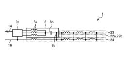
- FIG. 16 shows that in the outdoor unit 1 of the air conditioner according to the first embodiment, when the heat exchanger 6 and the casing 2 are brought into direct contact without going through the insulating member 7, a current that causes electromagnetic noise is transmitted.
- FIG. 3 is a circuit diagram in which a route is converted into an equivalent circuit.
- parasitic capacitances 22a, 22b as shown in FIG. 16 are generated between the heat exchanger 6 and the housing floor panel 2a shown in FIG. 15 and between the heat exchanger 6 and the housing top panel 2b. There is no change in voltage across the gap, and no electromagnetic noise is generated in the gaps G1, G2, G3, and G4.
- G4 can be prevented from generating electromagnetic noise and the radiation of electromagnetic noise to the outside of the housing 2 can be reduced. occurs.
- the insulating member 7 is provided between the heat exchanger 6 and the casing 2, corrosion of the heat exchanger 6, which has a low natural potential at the contact point between the heat exchanger 6 and the casing 2, can be prevented; Electromagnetic noise is generated in the gaps G1, G2, G3, and G4, and the amount of electromagnetic noise radiated to the outside of the housing 2 increases.
- a box-shaped casing 2 is formed of a first metal, and a casing 2 is formed of a second metal whose natural potential is different from that of the first metal.
- the heat exchanger 6 is disposed inside the housing 2 and is fixed to the housing 2 via an insulating member 7, and the conductive member 3 is made of a non-metallic material and is placed inside the housing 2.
- the conductive member 3 is fixed to and electrically connected to the casing 2 and is also electrically connected to the heat exchanger 6 . With these configurations, the heat exchanger 6 and the casing 2 are electrically connected via the conductive member 3. Therefore, the parasitic capacitances 22a and 22b generated between the heat exchanger 6 and each panel of the housing 2 shown in FIG.
- the conductive member 3 is fixed and electrically connected to the case side panel 2f and the partition panel 4, but the conductive member 3 is fixed to and electrically connected to the case side panel 2f and the partition panel 4, but the It may be fixed to all of the front panel 2a, the top panel 2b, the front panel 2e, the rear panel 2h, the side panels 2f and 2g, and the partition panel 4. In this way, the electrical connection between the panels is strengthened, and the contact resistance and parasitic inductance 23 of the housing 2 shown in FIG. 13 can be reduced. Therefore, electromagnetic noise transmitted to the electronic board 9c, the compressor 8, and each panel of the housing 2, ie, noise terminal voltage, interference power intensity, etc., can be reduced.
- the natural potential of the first metal is higher than the natural potential of the second metal, when the heat exchanger 6 and the casing 2 are brought into direct contact, the second metal Corrosion will occur in the formed heat exchanger 6.
- the heat exchanger 6 and the casing 2 do not come into direct contact as described above, corrosion of the heat exchanger 6 can be prevented.
- the first metal is iron or an iron alloy
- the strength of the casing 2 made of the first metal can be increased.
- the second metal is aluminum or an aluminum alloy, the thermal conductivity of the heat exchanger 6 formed of the second metal can be increased.
- serpentine heat exchangers and aluminum parallel flow heat exchangers. Both serpentine heat exchangers and parallel flow heat exchangers have fins and refrigerant conduits. In a serpentine heat exchanger, aluminum is generally used for the fins, and copper is generally used for the refrigerant conduits.
- the standard electrode potentials of the respective metals have a relationship of aluminum ⁇ iron ⁇ copper. That is, the magnitude relationship of the standard electrode potential of each metal member is the relationship of fin ⁇ casing 2 ⁇ refrigerant conduit.
- the fins of a serpentine heat exchanger and the refrigerant conduit come into direct contact with the housing 2 and moisture adheres to the contact points, the fins, which have a lower standard electrode potential than the housing 2, will corrode. Although corrosion may occur, corrosion does not occur in the refrigerant conduit whose standard electrode potential is higher than that of the housing 2.
- an aluminum parallel flow heat exchanger aluminum is used as the material for the fins and refrigerant pipes, so if iron is used for the housing 2, both the fins and the refrigerant pipes will corrode. may occur. If corrosion occurs in the refrigerant conduit and a hole opens, the refrigerant in the refrigerant conduit will leak into the atmosphere. If the refrigerant leaks into the atmosphere, the heating and cooling functions of the air conditioner will be impaired. In this way, aluminum parallel flow heat exchangers are susceptible to corrosion, so it is important to take measures to prevent corrosion, and it is also important to take measures to reduce electromagnetic noise that is generated by taking measures to prevent corrosion. It is necessary to take appropriate measures.
- achieving both prevention of corrosion and reduction of electromagnetic noise by using the non-metallic conductive member 3 as in this embodiment means that the natural potential of the refrigerant conduit is lower than the natural potential of the surrounding members such as the casing 2. This is particularly useful when using a heat exchanger with a lower potential.
- the installation location and shape of the conductive member 3 are not limited to the illustrated example.
- the conductive member 3 may be fixed to the housing floor panel 2a, the housing top panel 2b, etc., or may be electrically connected to any surface of the heat exchanger 6.
- the shape of the conductive member 3 may be changed as appropriate so that the conductive member 3 can be electrically connected to the housing 2 and the heat exchanger 6.
- the entire heat exchanger 6 be formed of the second metal, and it is sufficient that at least a portion of the heat exchanger 6 be formed of the second metal.
- at least one of the fins of the heat exchanger 6 and the refrigerant conduit may be formed of the second metal.
- the configuration shown in the above embodiments is an example, and it is possible to combine it with another known technology, and a part of the configuration can be omitted or changed without departing from the gist. It is possible.
- 1 outdoor unit of air conditioner 2 housing, 2a housing floor panel, 2b housing top panel, 2c first connection panel, 2d second connection panel, 2e housing front panel, 2f, 2g housing Body side panel, 2h Housing back panel, 2i Air supply port, 2j Exhaust port, 2k Opening, 2m inner surface, 3 Conductive member, 3a First conductive member, 3b Second conductive member, 3c First plate part, 3d second plate part, 3e fixing part, 3f plate part, 3g connecting part, 4 partition panel, 4a first partition part, 4b second partition part, 4c introduction hole, 4d, 6i side surface, 5 blower, 5a strut, 5b fan motor, 5c propeller fan, 6 heat exchanger, 6a first heat exchange section, 6b second heat exchange section, 6c, 6d header, 6e refrigerant conduit, 6f fin, 6g, 6h Front, 7 Insulating member, 7a First insulating member, 7b Second insulating member, 8 Compressor, 8a Motor winding, 8b, 22
Landscapes
- Engineering & Computer Science (AREA)
- Mechanical Engineering (AREA)
- General Engineering & Computer Science (AREA)
- Chemical & Material Sciences (AREA)
- Combustion & Propulsion (AREA)
- Physics & Mathematics (AREA)
- Thermal Sciences (AREA)
- Other Air-Conditioning Systems (AREA)
Abstract
Description
図1は、実施の形態1にかかる空気調和機の室外機1を模式的に示した分解斜視図である。図1に示すように、空気調和機の室外機1は、筐体2と、複数の導電性部材3と、仕切りパネル4と、送風機5と、熱交換器6と、複数の絶縁部材7と、圧縮機8と、電子基板箱9とを備えている。以下、空気調和機の室外機1を単に室外機1と称する場合もある。
Claims (5)
- 第1の金属により形成されている箱状の筐体と、
少なくとも一部が前記第1の金属とは自然電位が異なる第2の金属により形成され、前記筐体内に配置されて非導電性部材を介して前記筐体に固定される熱交換器と、
非金属により形成されて、前記筐体内に配置される導電性部材と、を備え、
前記導電性部材は、前記筐体に固定されて前記筐体と電気的に接続されるとともに、前記熱交換器と電気的に接続されている空気調和機の室外機。 - 前記筐体は、筐体床面パネルと、前記筐体床面パネルの上方に配置される筐体天面パネルと、前記筐体床面パネルと前記筐体天面パネルとを連結する筐体前面パネル、筐体背面パネルおよび筐体側面パネルと、を有し、
前記導電性部材は、前記筐体床面パネル、前記筐体天面パネル、前記筐体前面パネル、前記筐体背面パネルおよび前記筐体側面パネルのうち少なくとも一つに固定されている請求項1に記載の空気調和機の室外機。 - 前記第1の金属の自然電位は、前記第2の金属の自然電位よりも高い請求項1または2に記載の空気調和機の室外機。
- 前記第1の金属は、鉄または鉄合金であり、
前記第2の金属は、アルミニウムまたはアルミニウム合金である請求項1から3のいずれか1項に記載の空気調和機の室外機。 - 前記熱交換器は、パラレルフロー型の熱交換器である請求項1から4のいずれか1項に記載の空気調和機の室外機。
Priority Applications (5)
| Application Number | Priority Date | Filing Date | Title |
|---|---|---|---|
| US18/844,835 US20250224124A1 (en) | 2022-05-13 | 2022-05-13 | Outdoor unit of air conditioner |
| JP2024520212A JP7785167B2 (ja) | 2022-05-13 | 2022-05-13 | 空気調和機の室外機 |
| CN202280095388.0A CN119096090A (zh) | 2022-05-13 | 2022-05-13 | 空调机的室外机 |
| DE112022007211.3T DE112022007211B4 (de) | 2022-05-13 | 2022-05-13 | Außeneinheit einer Klimaanlage |
| PCT/JP2022/020217 WO2023218639A1 (ja) | 2022-05-13 | 2022-05-13 | 空気調和機の室外機 |
Applications Claiming Priority (1)
| Application Number | Priority Date | Filing Date | Title |
|---|---|---|---|
| PCT/JP2022/020217 WO2023218639A1 (ja) | 2022-05-13 | 2022-05-13 | 空気調和機の室外機 |
Publications (1)
| Publication Number | Publication Date |
|---|---|
| WO2023218639A1 true WO2023218639A1 (ja) | 2023-11-16 |
Family
ID=88730179
Family Applications (1)
| Application Number | Title | Priority Date | Filing Date |
|---|---|---|---|
| PCT/JP2022/020217 Ceased WO2023218639A1 (ja) | 2022-05-13 | 2022-05-13 | 空気調和機の室外機 |
Country Status (5)
| Country | Link |
|---|---|
| US (1) | US20250224124A1 (ja) |
| JP (1) | JP7785167B2 (ja) |
| CN (1) | CN119096090A (ja) |
| DE (1) | DE112022007211B4 (ja) |
| WO (1) | WO2023218639A1 (ja) |
Citations (3)
| Publication number | Priority date | Publication date | Assignee | Title |
|---|---|---|---|---|
| JPH0886474A (ja) * | 1994-09-16 | 1996-04-02 | Hitachi Ltd | 空気調和機の室外機 |
| JP2014081139A (ja) * | 2012-10-16 | 2014-05-08 | Sharp Corp | 空気調和機 |
| KR20150009865A (ko) * | 2013-07-17 | 2015-01-27 | 삼성전자주식회사 | 실외 열교환기 고정구조 및 공기조화기 실외기 |
Family Cites Families (4)
| Publication number | Priority date | Publication date | Assignee | Title |
|---|---|---|---|---|
| US6390180B1 (en) * | 1999-12-10 | 2002-05-21 | Mark W. Olsen | Heat exchanger isolation device |
| JP2013015296A (ja) | 2011-07-06 | 2013-01-24 | Panasonic Corp | 空気調和機 |
| JP6583489B1 (ja) | 2018-06-15 | 2019-10-02 | ダイキン工業株式会社 | 熱交換ユニット |
| US20250123009A1 (en) | 2022-04-15 | 2025-04-17 | Mitsubishi Electric Corporation | Air conditioner outdoor unit |
-
2022
- 2022-05-13 US US18/844,835 patent/US20250224124A1/en active Pending
- 2022-05-13 JP JP2024520212A patent/JP7785167B2/ja active Active
- 2022-05-13 WO PCT/JP2022/020217 patent/WO2023218639A1/ja not_active Ceased
- 2022-05-13 CN CN202280095388.0A patent/CN119096090A/zh active Pending
- 2022-05-13 DE DE112022007211.3T patent/DE112022007211B4/de active Active
Patent Citations (3)
| Publication number | Priority date | Publication date | Assignee | Title |
|---|---|---|---|---|
| JPH0886474A (ja) * | 1994-09-16 | 1996-04-02 | Hitachi Ltd | 空気調和機の室外機 |
| JP2014081139A (ja) * | 2012-10-16 | 2014-05-08 | Sharp Corp | 空気調和機 |
| KR20150009865A (ko) * | 2013-07-17 | 2015-01-27 | 삼성전자주식회사 | 실외 열교환기 고정구조 및 공기조화기 실외기 |
Also Published As
| Publication number | Publication date |
|---|---|
| JPWO2023218639A1 (ja) | 2023-11-16 |
| JP7785167B2 (ja) | 2025-12-12 |
| DE112022007211B4 (de) | 2025-10-09 |
| US20250224124A1 (en) | 2025-07-10 |
| DE112022007211T5 (de) | 2025-03-13 |
| CN119096090A (zh) | 2024-12-06 |
Similar Documents
| Publication | Publication Date | Title |
|---|---|---|
| JP5925270B2 (ja) | 電力変換装置 | |
| CN209763320U (zh) | 空调器 | |
| JP2008121966A (ja) | 空気調和機の室外機 | |
| CN100586263C (zh) | 改进冷却的电源 | |
| WO2001016532A1 (en) | Air conditioner | |
| JPWO2018207240A1 (ja) | 電力変換装置の冷却構造 | |
| JPH06123449A (ja) | 空気調和機の室外ユニット | |
| US12326265B2 (en) | Outdoor unit for air-conditioning apparatus | |
| JP7612102B2 (ja) | 空気調和機の室外機 | |
| WO2023218639A1 (ja) | 空気調和機の室外機 | |
| WO2001016531A1 (en) | Air conditioner | |
| JP7799708B2 (ja) | 空気調和機の室外機 | |
| JP7228589B2 (ja) | 冷蔵庫 | |
| JP2019187000A (ja) | 電力変換装置 | |
| CN208508808U (zh) | 一种开关电源 | |
| JP7438434B1 (ja) | 空気調和機用回路構造体及び空気調和機 | |
| CN224201796U (zh) | 散热结构、电控盒及暖通设备 | |
| JP6186439B2 (ja) | Dc−dcコンバータ装置 | |
| US20250056766A1 (en) | Electric component module | |
| CN222634752U (zh) | 空调驱动装置及空调器 | |
| JPH11346069A (ja) | 電気機器 | |
| JPS6120205B2 (ja) | ||
| CN208285206U (zh) | 一种便于接线的开关电源 | |
| JP2005245164A (ja) | カーエアコン用インバータの筐体構造、及び、その筐体の組立方法 | |
| JP2002198671A (ja) | 電子部品の冷却構造 |
Legal Events
| Date | Code | Title | Description |
|---|---|---|---|
| 121 | Ep: the epo has been informed by wipo that ep was designated in this application |
Ref document number: 22941716 Country of ref document: EP Kind code of ref document: A1 |
|
| ENP | Entry into the national phase |
Ref document number: 2024520212 Country of ref document: JP Kind code of ref document: A |
|
| WWE | Wipo information: entry into national phase |
Ref document number: 18844835 Country of ref document: US |
|
| WWE | Wipo information: entry into national phase |
Ref document number: 202427075955 Country of ref document: IN |
|
| WWE | Wipo information: entry into national phase |
Ref document number: 202280095388.0 Country of ref document: CN |
|
| WWE | Wipo information: entry into national phase |
Ref document number: 2401007360 Country of ref document: TH |
|
| WWE | Wipo information: entry into national phase |
Ref document number: 112022007211 Country of ref document: DE |
|
| WWP | Wipo information: published in national office |
Ref document number: 112022007211 Country of ref document: DE |
|
| 122 | Ep: pct application non-entry in european phase |
Ref document number: 22941716 Country of ref document: EP Kind code of ref document: A1 |
|
| WWP | Wipo information: published in national office |
Ref document number: 18844835 Country of ref document: US |
|
| WWG | Wipo information: grant in national office |
Ref document number: 112022007211 Country of ref document: DE |