WO2023218528A1 - 脚付きチェア - Google Patents
脚付きチェア Download PDFInfo
- Publication number
- WO2023218528A1 WO2023218528A1 PCT/JP2022/019811 JP2022019811W WO2023218528A1 WO 2023218528 A1 WO2023218528 A1 WO 2023218528A1 JP 2022019811 W JP2022019811 W JP 2022019811W WO 2023218528 A1 WO2023218528 A1 WO 2023218528A1
- Authority
- WO
- WIPO (PCT)
- Prior art keywords
- backrest
- seat
- chair
- legs
- leg fixing
- Prior art date
- Legal status (The legal status is an assumption and is not a legal conclusion. Google has not performed a legal analysis and makes no representation as to the accuracy of the status listed.)
- Ceased
Links
Images












Classifications
-
- A—HUMAN NECESSITIES
- A47—FURNITURE; DOMESTIC ARTICLES OR APPLIANCES; COFFEE MILLS; SPICE MILLS; SUCTION CLEANERS IN GENERAL
- A47C—CHAIRS; SOFAS; BEDS
- A47C3/00—Chairs characterised by structural features; Chairs or stools with rotatable or vertically-adjustable seats
- A47C3/02—Rocking chairs
- A47C3/025—Rocking chairs with seat, or seat and back-rest unit, elastically mounted in a rigid frame
Definitions
- the present invention relates to a chair with legs.
- a chair with legs that has a seat portion, a backrest portion, and leg portions.
- the backrest portion is tiltably supported by a tilting device.
- the present invention was completed based on the above circumstances, and an object of the present invention is to provide a chair with legs that can easily hold a seated person in a correct posture.
- a chair with legs includes a seat part, a backrest part, and leg parts that support the seat part, and a central recessed part is formed on both left and right sides of the rear part of the seat part and the lower part of the backrest part.
- the seat portion is fixed by the leg portions, and the backrest portion is displaced rearward when subjected to a rearward force.
- the legged chair according to the second aspect of the present invention includes a seat part, a backrest part, and legs supporting the seat part, and the upper surface of the seat part has a shape that causes the seated person to lean forward when sitting.
- the surface part is fixed by the legs so that the angle of the upper surface of the seat part does not change when the seated person sits on the seat, and when the seat part is not fixed by the legs, It is characterized in that the angle of the upper surface of the surface portion can be changed depending on the seated person.
- the seated person's buttocks and back tend to settle in the center portions of the seat surface and the backrest in the left-right direction, so the posture of the seated person tends to be straight.
- the backrest portion supports the back of the seated person and is appropriately displaced, so that it easily fits the back of the seated person. Therefore, it is possible to easily hold the seated person in a correct posture.
- the upper surface of the seat portion has a shape that causes the seated person to lean forward when sitting, so that the seated person's pelvis can stand upright. Since the angle of the upper surface of the seat portion is not changed by the seating of the seater, it is possible to exert the posture correcting function as intended in the shape design. Therefore, it is possible to easily hold the seated person in a correct posture.
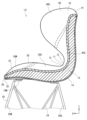
- Side view showing a chair with legs 4 is a cross-sectional view showing the main body and the upper part of the leg of the chair with legs, and corresponds to the cross-section at the AA position in FIG. 3.
- a diagram schematically showing changes in the thickness dimension of the core material Bottom view showing a chair with legs Bottom view of the main body showing the leg fixing part
- FIG. 7 is a partially enlarged cross-sectional view of the legged chair showing the front leg fixing part and the rear leg fixing part, and corresponds to the cross section at the BB position in FIG. 6.
- FIG. 7 is a partially enlarged cross-sectional view of the legged chair showing the left and right front leg fixing parts, and corresponds to the cross-section at the CC position in FIG. 6.
- FIG. 7 is a partially enlarged cross-sectional view of the legged chair showing the left and right rear leg fixing parts, and corresponds to the cross-section at the DD position in FIG. 6.
- Front view showing a chair with legs in Example 2 Side view showing a chair with legs
- Top view showing a chair with legs 14 is a cross-sectional view showing the main body and the upper part of the leg of the chair with legs, and corresponds to the cross-section at the EE position in FIG. 13.
- FIG. 16 is a partially enlarged cross-sectional view of the legged chair showing left and right front leg fixing parts, and corresponds to the cross-section at the FF position in FIG. 15.
- Front view showing a chair with legs in Example 3 Side view showing a chair with legs
- Top view showing a chair with legs 20 is a cross-sectional view showing the main body and the upper part of the legs of the chair with legs, and corresponds to the cross-section at the GG position in FIG. 20.
- FIG. 22 is a partially enlarged cross-sectional view of the legged chair showing left and right rear leg fixing parts, and corresponds to the cross-section at the HH position in FIG. 22.
- Front view showing a chair with legs in Example 4 Side view showing a chair with legs Top view showing a chair with legs 27 is a cross-sectional view showing the main body and the upper part of the leg of the chair with legs, and corresponds to the cross-section at the II position in FIG. 27.
- a point of the seat portion corresponding to the ischial tuberosity of the seated person is a seat reference point
- a straight line extending horizontally in the front-rear direction through the seat reference point is a seat reference line
- the point corresponding to the uppermost end of the horizontal center of the backrest portion when the backward force is zero is the backrest reference point
- the straight line extending vertically through the backrest reference point is the backrest reference line
- the seat reference line and the backrest reference line is the reference intersection
- a point corresponding to the backrest reference point when the backrest is displaced rearward is the backrest displacement point
- a straight line passing through the backrest displacement point and the reference intersection is the backrest.
- the backrest displacement angle may be from 0 degrees to 30 degrees. According to such a configuration, the backrest supports the back of the seated person and is appropriately displaced, so that it easily fits the back of the seated person. Therefore, it is possible to easily hold the seated person in a correct posture.
- the seat portion and the backrest portion have a core member that is connected at a rear portion of the seat portion and a lower portion of the backrest portion, and the backrest portion has a core member that It may be displaced to the rear side by. According to such a configuration, the displacement occurs due to the bending of the core material connected to the rear part of the seat part and the lower part of the backrest part, so there is no need for a support member to support the backrest part. Therefore, the chair with legs can have a simple design.
- the thickness of the core material at the rear part of the seat part and the lower part of the backrest part is the same as that of the upper part of the backrest part and the front part of the seat part of the core material. It may be larger than the thickness dimension. According to such a configuration, the backrest portion is appropriately displaced by the flexure of the core material, thereby improving the sitting comfort of the seated person.
- the lower surface of the seat part has a curved shape
- the leg fixing part for fixing the leg part to the seat part is provided to protrude from the lower surface of the seat part, and It has a front leg fixing part provided in the front area of the lower surface of the seat part and a rear leg fixing part provided in the rear area, and the protruding dimension of the front leg fixing part and the protruding dimension of the rear leg fixing part are It may be different. According to such a configuration, the legs can be properly fixed to the lower surface of the seat part, and the seat part and the backrest part can be correctly installed with respect to the floor surface.
- Example 1 Hereinafter, the legged chair L1 of Example 1 embodying the present invention will be described in detail with reference to FIGS. 1 to 10.
- the upper side of the legged chair L1 when standing on the floor is the upper side
- the lower side is the lower side
- the front side is the front side and the rear side is referred to as the seated person sitting on the legged chair L1.
- the right side will be referred to as the right side
- the left side will be referred to as the left side.
- the positive side of the X axis is the front side
- the negative side of the X axis is the rear side
- the positive side of the Y axis is the right side
- the negative side of the Y axis is the left side
- the positive side of the Z axis is the top side
- the The negative side of the axis indicates the lower side.
- the XY plane is a horizontal plane.
- the Z axis extends vertically.
- the legged chair L1 includes a main body 10 and leg parts 20 that support the main body 10.
- the legged chair L1 is symmetrical with respect to the center in the left-right direction.
- the main body part 10 has a seat part 30 and a backrest part 40.
- the seat portion 30 supports the buttocks and the base of the thighs of the seated person from below.
- the backrest portion 40 supports the back of the seated person from the rear side.
- the back region includes the lumbar region and back of the seated person.
- the seat portion 30 and the backrest portion 40 are integrally formed.
- the seat portion 30 has seat edges 31 at both left and right ends, and a seat center portion 32 at the center in the left and right direction. In the YZ plane, the upper ends of the left and right seat edge portions 31 are located above the upper end of the seat center portion 32.
- Two seat curved portions 33 are formed on the upper surface of the seat portion 30. Each seat curved portion 33 is recessed downward between the upper end of the seat edge 31 and the upper end of the seat center portion 32. The bases of the left and right thighs of the seated person are supported by the left and right seat curved portions 33, respectively. The bases of the thighs of the seated person are difficult to open to the left and right sides by the left and right seat edges 31. The left and right seat edges 31 can be elastically displaced downward. As shown in FIG. 8, the seat curved portion 33 has a central portion recessed downward in the front-rear direction as well.
- the seat part 30 is slightly tilted forward, and the front part 30M of the seat part 30 is lower than the rear part 30U of the seat part 30.
- the front portion 30M of the seat portion 30 is located at a lower position than the rear height reference point P20 of the seat portion 30.
- the rear height reference point P20 of the seat portion 30 is the intersection of the core material 14 and a bisector S10 of the intersection angle of the seat reference line S1 and the backrest reference line S2, which will be described later.
- the front portion 30M of the seat portion 30 is located below a horizontal imaginary straight line S11 passing through the rear height reference point P20.
- the upper part 40U of the backrest part 40 has an upper recessed part 41 formed in the center in the left-right direction, and two upper support parts 42 that stand on both left and right sides of the upper recessed part 41. There is.
- the maximum dimension of the backrest portion 40 in the vertical direction is smaller than the maximum dimension of the backrest portion 40 in the horizontal direction.
- the horizontal dimension of the portion of the backrest portion 40 below the lower end of the upper recessed portion 41 gradually decreases downward.
- the backrest portion 40 has a form that rises upward from the rear end of the seat portion 30 when viewed from the side.
- the left and right side edges 43 of the backrest portion 40 have a curved shape that bulges forward.
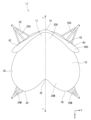
- central recesses 12 are formed on both left and right sides of the lower portion 40S of the backrest portion 40 and the rear portion 30U of the seat portion 30 (see FIG. 1).
- the central recessed portion 12 is recessed toward the center in the left-right direction when viewed from the front. Thereby, the backrest portion 40 can be appropriately tilted rearward while maintaining the strength at the boundary between the backrest portion 40 and the seat surface portion 30.
- the lower part 40S of the backrest part 40 and the rear part 30U of the seat part 30 are referred to as the main body central part 11.
- the horizontal dimension of the main body part 10 gradually increases from the main body center part 11 toward the upper part of the backrest part 40. This can reduce the tightness of the back of the seated person.
- the horizontal dimension of the main body part 10 gradually increases from the main body center part 11 toward the front of the seat surface part 30 (see FIG. 3). Thereby, the tightness of the buttocks of the seated person can be reduced.
- the left and right side edges 13 of the main body central portion 11 are curved and recessed toward the rear side when viewed from the side.
- the left and right side edges 13 of the main body central portion 11 form a central recessed portion 12 .
- the two upper support parts 42 of the backrest part 40 extend diagonally forward from the center side in the left-right direction of the backrest part 40 toward both end sides in the left-right direction in a plan view. Both end portions of the front surface of the backrest portion 40 in the left-right direction are located forward of the center portion in the left-right direction.
- the front portion 30M of the seat portion 30 includes a front recess 35 formed at the center in the left-right direction and two front protrusions 36 provided on both left and right sides of the front recess 35. have.
- the left-right dimension of the portion of the seat portion 30 on the rear side of the rear end of the front recessed portion 35 gradually decreases toward the rear.
- the front protrusion 36 projects diagonally downward from the rear end of the front recess 35 toward the front end (see FIG. 4).
- the main body central portion 11 has a continuous curved shape from the rear portion 30U of the seat portion 30 to the lower portion 40S of the backrest portion 40.
- the main body central portion 11 has a spherical shape as a whole (see FIG. 10).
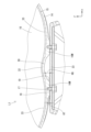
- the main body portion 10 has a core material 14 and a cushion 15, as shown in FIG.
- the core material 14 is made of hard synthetic resin such as polypropylene.
- the core material 14 is in the shape of a single curved plate that forms the overall shape of the main body portion 10.
- the core material 14 is a single member and forms the entire seat portion 30 and the entire backrest portion 40.
- the core material 14 is continuous at the rear portion 30U of the seat portion 30 and the lower portion 40S of the backrest portion 40.
- the front surface of the front and back surfaces of the core material 14 is parallel to the upper surface of the seat portion 30 and the front surface of the backrest portion 40.
- the surface of the core material 14 is the surface on which a seated person sits.
- Parallel includes a substantially parallel state in addition to a strictly parallel state.
- the back surface of the core material 14 constitutes the lower surface of the seat portion 30 and the rear surface of the backrest portion 40.
- the back surface of the core material 14 is the surface opposite to the side on which the seated person sits.
- the core material 14 has rigidity (shape retention) that can stably maintain the posture of the seated person.
- shape retention shape retention
- the core material 14 receives force from sitting on the seat, it can be elastically deformed to the extent that it does not affect the posture of the seated person.
- the backrest portion 40 receives a backward force, the backrest portion 40 is displaced rearward due to the flexure of the core member 14. The displacement of the backrest portion 40 will be explained in detail later.
- the thickness of the core material 14 is a dimension that ensures strength enough to withstand the load acting on the main body portion 10, and a dimension that realizes appropriate deflection to maintain the correct posture of the seated person.
- the thickness dimension of the core material 14 is the length dimension in the direction perpendicular to the surface of the core material 14.
- the thickness of the core material 14 is greatest at the center portion 11 of the main body.
- the thickness dimension of the core material 14 in the main body central portion 11 is generally constant.
- the main body central portion 11 includes the most recessed portion of the central recessed portion 12, as shown in FIG.
- the thickness of the core material 14 gradually becomes thinner from the center portion 11 of the main body toward the front and upper sides.
- the maximum value of the thickness dimension of the core material 14 is 4.7 mm, and the minimum value is 4.0 mm.
- the surface of the core material 14 is a smooth surface with no steps.
- FIG. 5 is a schematic view of the main body 10 viewed from the direction of arrow Ya in FIG. 4, in which a chain double-dashed line is drawn by connecting points where the thickness dimension of the core material 14 is equal.
- the two-dot chain line shown in FIG. 5 is curved along the curved shape of the main body portion 10.
- the thickness of the core material 14 varies depending on the curved shape.
- the cushion 15 is laminated on the surface of the core material 14.
- the cushion 15 is made of urethane foam or soft urethane foam.
- the cushion 15 may be made of open-cell polyurethane foam or the like.
- the thickness of the cushion 15 is smaller than that of the core material 14 and is generally constant throughout.
- the leg portion 20 includes front and rear legs 20M, 20U, a connecting member 21, and a brace 24.
- the front and rear legs 20M, 20U are provided in pairs on each side.
- the left and right front legs 20M and the left and right rear legs 20U are each opened from the upper end to the lower end on both sides.
- the front and rear legs 20M and 20U are open from the upper end to the lower end on both front and rear sides.
- the height H1 of the front legs 20M is larger than the height H2 of the rear legs 20U.
- the height H1 of the front leg 20M and the height H2 of the rear leg 20U are vertical lengths from the lower ends of the legs 20M, 20U to the upper ends of the legs 20M, 20U.
- the chair L1 with legs can suppress forward slipping of the seated person.
- It is desirable that the difference in height between the upper end of the front leg 20M and the upper end of the rear leg 20U is smaller than 9 mm.
- the height difference between the upper end of the front leg 20M and the upper end of the rear leg 20U is preferably 8 mm.
- the lower ends of the four legs 20M and 20U protrude in all directions from the main body 10 in plan view.
- the connecting member 21 connects the upper ends of the four legs 20M and 20U, and is fixed to the lower surface of the seat portion 30.
- the connecting member 21 has a vertical member 22 extending in the front-rear direction and a horizontal member 23 extending in the left-right direction.
- the horizontal member 23 extends horizontally as shown in FIG.
- the vertical member 22 is inclined slightly upward from the rear end toward the front end.
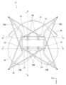
- a leg fixing part 16 for fixing the leg part 20 is provided on the lower surface of the seat part 30.
- the leg fixing section 16 includes two front leg fixing sections 16M and two rear leg fixing sections 16U.
- the two front leg fixing parts 16M are provided in the front region R1 of the lower surface of the seat part 30.
- the two rear leg fixing parts 16U are provided in the rear region R2 of the lower surface of the seat part 30.
- the front region R1 is a region on the front side of the center of the seat portion 30 in the front-rear direction when viewed from the bottom.
- the rear region R2 is a region on the rear side of the center of the seat portion 30 in the front-rear direction when viewed from the bottom.
- the left and right front leg fixing parts 16M and the left and right rear leg fixing parts 16U are symmetrical with respect to the center of the main body 10 in the left-right direction.
- the distance in the left-right direction between the front leg fixing portions 16M and the distance in the left-right direction between the rear leg fixing portions 16U are equal.
- the front leg fixing part 16M and the rear leg fixing part 16U each protrude downward from the lower surface of the seat part 30.
- the protruding dimensions of the front leg fixing part 16M and the rear leg fixing part 16U each become smaller toward the outer circumferential side (see FIG. 8).
- a hole 17 for a fastening member is formed in each of the front leg fixing part 16M and the rear leg fixing part 16U (see FIG. 8).
- the front leg fixing part 16M and the rear leg fixing part 16U each have a plurality of ribs 18.
- the plurality of ribs 18 extend radially around the hole 17 .
- the outer peripheral sides of the plurality of ribs 18 are surrounded by a peripheral wall 19.
- the ribs 18 and the peripheral wall 19 protrude downward from the lower surface of the seat portion 30.
- the protruding dimension of the front leg fixing part 16M and the protruding dimension of the rear leg fixing part 16U are different.
- the protrusion dimension of the front leg fixing part 16M from the seat surface part 30 is larger on the front side than on the rear side, and larger on the inner side than on the left and right outer sides.
- the protrusion dimension of the rear leg fixing part 16U from the seat surface part 30 is larger on the rear side than on the front side, and larger on both outer sides than on the left and right inner sides.
- the front leg fixing part 16M and the rear leg fixing part 16U are formed of the core material 14, as shown in FIG.
- the lower ends of the front leg fixing part 16M and the lower ends of the rear leg fixing part 16U are in contact with and fixed to the upper surface of the horizontal member 23.
- the lower surface of the seat portion 30 is curved into a spherical shape in the XZ plane.
- the protrusion dimension H3 of the front end of the front leg fixing part 16M is larger than the protrusion dimension H4 of the rear end of the front leg fixing part 16M.
- the protrusion dimension H5 of the front end of the rear leg fixing part 16U is smaller than the protrusion dimension H6 of the rear end of the rear leg fixing part 16U.
- the protrusion dimension H3 of the front end of the front leg fixing part 16M is smaller than the protrusion dimension H6 of the rear end of the rear leg fixing part 16U.
- the protrusion dimension H4 of the rear end of the front leg fixing part 16M is larger than the protrusion dimension H5 of the front end of the rear leg fixing part 16U.
- the protruding dimensions H3, H4, H5, and H6 are vertical lengths from the upper end to the lower end at the center in the left-right direction of the front leg fixing part 16M and the rear leg fixing part 16U.
- the lower surface of the front region R1 of the seat portion 30 is curved parallel to the two seat curved portions 33 in the left-right direction, as shown in FIG.
- the left and right front leg fixing parts 16M are provided inside the lower ends of the left and right seat curved parts 33.
- the protrusion dimension H7 of the outer end in the left and right direction of the left and right front leg fixing parts 16M is smaller than the protrusion dimension H8 of the inner end in the left and right direction.
- the protruding dimensions H7 and H8 are the vertical lengths from the upper end to the lower end at the front-rear center of the front leg fixing portion 16M.
- the lower surface of the rear region R2 of the seat portion 30 is curved parallel to the main body central portion 11 in the left-right direction, as shown in FIG.
- the protrusion dimension H9 of the outer ends of the left and right rear leg fixing parts 16U in the left-right direction is larger than the protrusion dimension H10 of the inner ends in the left-right direction.
- the protruding dimensions H9 and H10 are vertical lengths from the upper end to the lower end at the center of the rear leg fixing portion 16U in the front-rear direction.
- the displacement angle of the backrest portion 40 (referred to as backrest displacement angle ⁇ ) is 0 degrees to 30 degrees (see FIG. 4).
- the backrest displacement angle ⁇ includes 0 degrees and 30 degrees.
- the backrest displacement angle ⁇ is preferably 5 degrees to 10 degrees.
- the backrest displacement angle ⁇ is an acute angle between the backrest reference line S2 and the backrest displacement line S3.
- the backrest displacement angle ⁇ is a value measured when a pressing force F of 100 N is applied from the front to the point of action P10 on the front surface of the backrest portion 40, as shown in FIG.
- the pressing force F is a force parallel to the X axis. As shown in FIG. 1, the pressing force F is applied to a point of application P10 on the front surface of the backrest portion 40.
- the position of the point of action P10 indicates a height position where the back of the seated person and the backrest 40 tend to come into strong contact with each other when the seated person leans against the backrest 40.
- the height position of the point of action P10 is determined in consideration of the height dimension of the iliac crest of the seated person.
- the height dimension of the iliac crest is the vertical dimension between the highest position of the upper edge of the iliac crest of a person seated on the seat surface of a chair and the seat surface.
- the height of the iliac crest varies from 170 mm to 255 mm depending on the body physique.
- the backrest reference line S2 is a straight line that extends vertically through the backrest reference point P2.
- the backrest reference point P2 is a point corresponding to the uppermost end of the backrest portion 40 at the center in the left-right direction when the backward force is zero (the state shown in FIG. 4).
- the backrest reference point P2 is located on the rear surface of the backrest portion 40 at the center of the backrest portion 40 in the left-right direction.
- the backrest displacement line S3 is a straight line passing through the backrest displacement point P4 and the reference intersection P3.
- the backrest displacement point P4 indicates the position of the backrest reference point P2 when the backrest portion 40 is displaced by a backward force.
- the reference intersection P3 is the intersection of the seat reference line S1 and the backrest reference line S2.
- the seat reference line S1 is a straight line that passes through the seat reference point P1 and extends horizontally in the front-rear direction.
- the seat reference point P1 is a point of the seat portion 30 that corresponds to the ischial tuberosity of the seated person.
- the seat reference point P1 is located directly below the center of the left and right ischial tuberosities of the seated person in the left-right direction.
- the seat reference point P1 is located on the lower surface of the seat portion 30 at the center of the seat portion 30 in the left-right direction.
- the seat reference line S1 is parallel to the X-axis.
- the backrest reference line S2 is parallel to the Z-axis.
- the seat reference point P1, the backrest reference point P2, the reference intersection P3, the backrest displacement point P4, the seat reference line S1, the backrest reference line S2, and the backrest displacement line S3 are virtual points and lines on the same XZ plane.
- the point corresponding to the ischial tuberosity of the seated person is based on the point when the seated person of a standard physique is seated on the legged chair L1 in a standard posture.
- a standard physique is a physique that is neither overweight nor too thin.
- a standard posture is a posture that does not fall under either hunched back or arched back.
- the backrest displacement angle ⁇ is 9. .2 degrees.
- the amount of displacement D of the backrest portion 40 at this time is 36 mm.
- the displacement amount D of the backrest portion 40 is the distance parallel to the X-axis between the backrest reference point P2 and the backrest displacement point P4.
- a seated person places the legged chair L1 on the floor and sits on the main body 10. Since the main body portion 10 is fixed to the leg portions 20, it does not tilt or the like when a person sits on the seat.
- the buttocks of the seated person are supported by the central portion 11 of the main body having a spherical concave shape. Thereby, the buttocks of the seated person are stably supported from the front and rear directions and from the left and right directions.
- the seated person's pelvis is in an upright position, and the seated person's back muscles are naturally stretched.
- the bases of both thighs of the seated person are supported by two seat curved portions 33 having a concave curved shape. As a result, the lower limbs of the seated person are supported in a parallel and aligned state.
- the lumbar region of the seated person is supported by the front surface of the backrest portion 40.
- the left and right upper support parts 42 are appropriately elastically displaced rearward.
- the lower back of the seated person is prevented from tilting to both the left and right sides by the left and right upper support parts 42.
- the left and right side edges 43 of the backrest portion 40 support the position of the ilium of the seated person.
- the lumbar region of the seated person is supported in a correct posture, allowing the seated person to stand up naturally without straining and providing good sitting comfort.
- the backrest portion 40 flexes appropriately and assumes an angle suitable for the seated person. As a result, excessive inclination of the backrest portion 40 and the feeling of being cramped by the backrest portion 40 can be reduced, and the seated person can maintain a correct posture for a long time without feeling almost fatigued.
- the legged chair L1 of Example 1 includes a seat portion 30, a backrest portion 40, and leg portions 20 that support the seat portion 30.
- a central depression 12 is formed on both sides of the rear portion 30U of the seat portion 30 and the lower portion 40S of the backrest portion 40 in the left-right direction.
- the seat portion 30 is fixed by the leg portions 20.
- the backrest portion 40 is displaced rearward when subjected to a backward force. According to this configuration, the buttocks and back of the seated person tend to settle in the center portion of the seat portion 30 and the backrest portion 40 in the left-right direction, so that the posture of the seated person tends to be straight. Therefore, it is possible to easily hold the seated person in a correct posture.
- the point corresponding to the ischial tuberosity of the seated person on the seat part 30 is the seat reference point P1
- the straight line extending horizontally in the front-rear direction through the seat reference point P1 is the seat reference line S1
- the rearward force is zero.
- the point corresponding to the uppermost end of the backrest portion 40 in the horizontal direction in a certain state is the backrest reference point P2
- the straight line extending vertically through the backrest reference point P2 is the backrest reference line S2
- the intersection with the backrest 40 is the reference intersection P3, the point corresponding to the backrest reference point P2 when the backrest portion 40 is displaced to the rear is the backrest displacement point P4, and the straight line passing through the backrest displacement point P4 and the reference intersection P3 is the backrest displacement line S3.
- the backrest displacement angle ⁇ is 0 degrees to 30 degrees.
- the backrest portion 40 supports the back of the seated person and is appropriately displaced, so that it easily fits the back of the seated person. Therefore, it is possible to easily hold the seated person in a correct posture.
- the seat part 30 and the backrest part 40 have a core member 14 that is connected at the rear part 30U of the seat part 30 and the lower part 40S of the backrest part 40.
- the backrest portion 40 is displaced rearward due to the bending of the core material 14. According to this configuration, since the displacement occurs due to the bending of the core material 14 that is connected to the rear portion 30U of the seat portion 30 and the lower portion 40S of the backrest portion 40, a support member for supporting the backrest portion 40 is not required. Therefore, the chair L1 with legs can have a simple design.
- the thickness of the core material 14 at the rear part 30U of the seat part 30 and the lower part 40S of the backrest part 40 is larger than the thickness dimension of the upper part 40U of the backrest part 40 and the front part 30M of the seat part 30 in the core material 14. .
- the backrest portion 40 is appropriately displaced by the bending of the core material 14, so that the sitting comfort of the seated person can be improved.
- the lower surface of the seat portion 30 has a curved shape.
- the leg fixing part 16 that fixes the leg part 20 to the seat part 30 is provided to protrude from the lower surface of the seat part 30.
- the leg fixing portion 16 includes a front leg fixing portion 16M provided in a front region R1 of the lower surface of the seat portion 30 and a rear leg fixing portion 16U provided in a rear region R2.
- the protruding dimension of the front leg fixing part 16M and the protruding dimension of the rear leg fixing part 16U are different. According to this configuration, the leg part 20 can be properly fixed to the lower surface of the seat part 30, and the seat part 30 and the backrest part 40 can be correctly installed with respect to the floor surface.
- the legged chair L1 of Example 1 includes a seat portion 30, a backrest portion 40, and leg portions 20 that support the seat portion 30.
- the upper surface of the seat portion 30 has a shape that allows the seated person to lean forward when seated.
- the seat portion 30 is fixed by the leg portions 20, so that the angle of the upper surface of the seat portion 30 does not change when a person sits on the seat.
- the angle of the upper surface of the seat portion 30 may be changed by the seating of the seater.
- the upper surface of the seat portion 30 has a shape that causes the seated person to lean forward when sitting, so that the seated person's pelvis can stand upright. Since the angle of the upper surface of the seat portion 30 is not changed by the seating of the seater, it is possible to exert the posture correcting function as intended in the shape design. Therefore, it is possible to easily hold the seated person in a correct posture.
- the posture correcting function of the posture correcting device cannot be maximized.
- the seat part 30 of the legged chair L1 is fixed by the leg parts 20, there is no need to place it on an existing chair, and the inclination angle can be changed depending on how the seated person puts their weight when sitting. Therefore, it is possible to exhibit the posture correction function as intended in the shape design.
- Example 2 a chair L2 with legs according to a second embodiment of the present invention will be described with reference to FIGS. 11 to 17.
- the legged chair L2 of this embodiment differs from the first embodiment in that the thickness of the cushion 15 is larger than the thickness of the core material 14. Note that the same components as in the first embodiment are given the same reference numerals and redundant explanations will be omitted.
- the legged chair L2 includes a main body section 10 having a seat section 30 and a backrest section 40, and leg sections 20.
- the upper portion 40U of the backrest portion 40 has an upper recessed portion 41 and two upper support portions 42, as in the first embodiment.
- the maximum dimension of the backrest portion 40 in the vertical direction is larger than the maximum dimension of the backrest portion 40 in the horizontal direction.
- the backrest portion 40 is displaced rearward when subjected to a backward force.
- the backrest displacement angle ⁇ is 0 degrees to 30 degrees, as in the first embodiment.
- the seat portion 30 has a seat edge portion 31 and a seat center portion 32, as in the first embodiment.
- Two seat curved portions 33 are formed on the upper surface of the seat portion 30.
- the main body central portion 11 has central recesses 12 formed on both left and right sides, similar to the first embodiment.
- the main body central portion 11 has a continuous curved shape from the rear portion 30U of the seat portion 30 to the lower portion 40S of the backrest portion 40 (see FIG. 14).
- the main body portion 10 includes a core material 14 and a cushion 15, as in the first embodiment.
- the cushion 15 is made of urethane foam, for example.
- the thickness of the cushion 15 is larger than that of the core material 14.
- the thickness of the core material 14 is greatest at the center portion 11 of the main body.
- the thickness of the cushion 15 is greatest at the central portion 11 of the main body.
- the thickness of the cushion 15 gradually becomes thinner from the center portion 11 of the main body toward the front and upper sides.
- the maximum value of the thickness dimension of the core material 14 is 9.1 mm, and the minimum value is 4.0 mm.
- the radius of curvature of the surface of the cushion 15 in the central portion 11 of the main body is smaller than the radius of curvature of the core material 14.
- the leg portion 20 includes front and rear legs 20M and 20U, a connecting member 21, and a brace 24, as in the first embodiment.
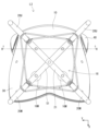
- the connecting member 21 has two diagonal members 51 that cross at the center of the seat portion 30 in plan view. The lower ends of the front leg fixing part 16M and the lower ends of the rear leg fixing part 16U touch and are fixed to the upper surface of the diagonal member 51 (see FIG. 17).
- the leg fixing portion 16 is provided on the lower surface of the seat portion 30, as in the first embodiment.
- the leg fixing section 16 includes two front leg fixing sections 16M and two rear leg fixing sections 16U.
- the protruding dimension of the front leg fixing part 16M and the protruding dimension of the rear leg fixing part 16U change along the curved shape of the lower surface of the seat part 30, as in the first embodiment. Similar to the first embodiment, the protrusion dimension of the rear leg fixing part 16U from the seat surface part 30 is larger on the rear side than on the front side, and larger on both outer sides than on the left and right inner sides.
- the left and right front leg fixing parts 16M are provided at the lower end positions of the left and right seat curved parts 33, as shown in FIG.
- the protrusion dimension H7 of the outer end in the left-right direction of the left and right front leg fixing parts 16M is slightly larger than the protrusion dimension H8 of the inner end in the left-right direction.
- the legged chair L2 of the second embodiment includes a seat part 30, a backrest part 40, and leg parts 20 that support the seat part 30, and the backrest displacement angle ⁇ is 0 degrees to 30 degrees. degree. Therefore, similarly to the first embodiment, it is possible to easily hold the seated person in a correct posture.
- the angle of the upper surface of the seat part 30 of the legged chair L2 of the second embodiment is fixed by the legs 20 and does not change as in the first embodiment, so that the posture correction can be performed as intended in the shape design. Able to perform functions. Therefore, similarly to the first embodiment, it is possible to easily hold the seated person in a correct posture.
- Example 3 a chair L3 with legs according to a third embodiment of the present invention will be described with reference to FIGS. 18 to 24.
- the legged chair L3 of this embodiment differs from the second embodiment in that it has an intermediate member 61 between the core material 14 and the cushion 15. Note that configurations similar to those in Example 2 are given the same reference numerals and redundant explanations will be omitted.
- the legged chair L3 includes a main body section 10 having a seat section 30 and a backrest section 40, and leg sections 20.
- the upper portion 40U of the backrest portion 40 has an upper recessed portion 41 and two upper support portions 42, as in the second embodiment.
- the maximum dimension of the backrest portion 40 in the vertical direction is smaller than the maximum dimension of the backrest portion 40 in the horizontal direction.
- the backrest portion 40 is displaced rearward when subjected to a backward force.
- the backrest displacement angle ⁇ is 0 degrees to 30 degrees, as in the second embodiment.
- the seat portion 30 has a seat edge portion 31 and a seat center portion 32, as in the second embodiment.
- Two seat curved portions 33 are formed on the upper surface of the seat portion 30.
- the main body central portion 11 has central recesses 12 formed on both left and right sides, similar to the second embodiment.
- the main body central portion 11 has a continuous curved shape from the rear portion 30U of the seat portion 30 to the lower portion 40S of the backrest portion 40 (see FIG. 21).
- the main body portion 10 includes a core material 14 and a cushion 15, as in the second embodiment.
- the thickness of the cushion 15 is larger than the thickness of the core material 14, as in the second embodiment.
- the cushion 15 is made of, for example, low-resilience urethane foam.
- the thickness dimension of the core material 14 is generally constant throughout.
- the thickness of the cushion 15 is greater at the center portion 11 of the main body and at the backrest portion 40.
- the thickness of the cushion 15 is approximately constant in the seat portion 30.
- the intermediate member 61 has a plate shape parallel to the surface of the core material 14 and has the same shape as the core material 14 as a whole.
- the thickness of the intermediate member 61 is smaller than the thickness of the core material 14 as a whole.
- the thickness of the core material 14 is 4 mm, and the thickness of the intermediate member 61 is 3 mm.
- the intermediate member 61 has a frame portion 62 that is provided along the outer edge and protrudes toward the front side.
- the frame portion 62 supports the outer edge portion of the cushion 15.
- the leg portion 20 includes front and rear legs 20M, 20U, a connecting member 21, and a brace 24, as in the second embodiment.
- the leg fixing portion 16 is provided on the lower surface of the seat portion 30, as in the second embodiment.
- the leg fixing section 16 includes two front leg fixing sections 16M and two rear leg fixing sections 16U.
- the two rear leg fixing parts 16U are arranged at positions closer to the rear than in the second embodiment.
- the protruding dimension of the front leg fixing part 16M and the protruding dimension of the rear leg fixing part 16U change along the curved shape of the lower surface of the seat part 30, as in the second embodiment.
- the protrusion dimension of the rear leg fixing part 16U from the seat surface part 30 is so small that it is difficult to visually recognize it when viewed from the side.
- the protrusion dimension H9 of the outer end in the left-right direction of the left and right rear leg fixing parts 16U is slightly larger than the protrusion dimension H10 of the inner end in the left-right direction.
- the legged chair L3 of the third embodiment includes a seat portion 30, a backrest portion 40, and leg portions 20 that support the seat portion 30, and the backrest displacement angle ⁇ is 0 degrees to 30 degrees. degree. Therefore, similarly to the second embodiment, it is possible to easily hold the seated person in a correct posture.
- the angle of the upper surface of the seat part 30 of the legged chair L3 of the third embodiment is fixed by the leg parts 20 and does not change as in the second embodiment, so that the posture correction can be performed as intended in the shape design. Able to perform functions. Therefore, similarly to the second embodiment, it is possible to easily hold the seated person in a correct posture.
- Example 4 a chair L4 with legs according to a fourth embodiment of the present invention will be explained with reference to FIGS. 25 to 30.
- the legged chair L4 of this embodiment differs from the second embodiment in that it has an exterior sheet 71 on the surface of the cushion 15. Note that configurations similar to those in Example 2 are given the same reference numerals and redundant explanations will be omitted.
- the legged chair L4 includes a main body section 10 having a seat section 30 and a backrest section 40, and leg sections 20.
- the upper portion 40U of the backrest portion 40 has an upper recessed portion 41 and two upper support portions 42, as in the second embodiment.
- the maximum dimension of the backrest portion 40 in the vertical direction is smaller than the maximum dimension of the backrest portion 40 in the horizontal direction.
- the backrest portion 40 is displaced rearward when subjected to a backward force.
- the backrest displacement angle ⁇ is 0 degrees to 30 degrees, as in the second embodiment.
- the seat portion 30 has a seat edge portion 31 and a seat center portion 32, as in the second embodiment.
- Two seat curved portions 33 are formed on the upper surface of the seat portion 30.
- the main body central portion 11 has central recesses 12 formed on both left and right sides, as in the second embodiment.
- the main body central portion 11 has a continuous curved shape from the rear portion 30U of the seat portion 30 to the lower portion 40S of the backrest portion 40 (see FIG. 28).
- the main body portion 10 includes a core material 14 and a cushion 15, as in the second embodiment.
- the thickness of the cushion 15 is larger than the thickness of the core material 14, as in the second embodiment.
- the cushion 15 is made of, for example, low-resilience urethane foam.
- the thickness of the core material 14 is greatest at the center portion 11 of the main body.
- the maximum value of the thickness dimension of the core material 14 is 7.8 mm, and the minimum value is 6.6 mm.
- the thickness of the cushion 15 is approximately constant in the backrest portion 40. The thickness of the cushion 15 decreases from the center portion 11 of the main body toward the front end of the seat portion 30.
- the exterior sheet 71 covers the entire surface of the cushion 15.
- the overall thickness of the exterior sheet 71 is smaller than that of the cushion 15.
- the leg portion 20 has front and rear legs 20M and 20U, and a brace 24, as in the second embodiment.
- the leg fixing part 16 is provided on the lower surface of the seat part 30, as in the second embodiment.
- the leg fixing section 16 includes two front leg fixing sections 16M and two rear leg fixing sections 16U.
- the two front leg fixing parts 16M are arranged closer to the front than in the second embodiment.
- the protrusion dimensions of the front leg fixing part 16M and the rear leg fixing part 16U from the seat part 30 change according to the curved shape of the lower surface of the seat part 30.
- the legged chair L4 of Example 4 includes a seat portion 30, a backrest portion 40, and leg portions 20 that support the seat portion 30, and the backrest displacement angle ⁇ is 0 degrees to 30 degrees. degree. Therefore, similarly to the second embodiment, it is possible to easily hold the seated person in a correct posture.
- the angle of the upper surface of the seat part 30 of the legged chair L4 of the fourth embodiment is fixed by the legs 20 and does not change as in the second embodiment, so that the posture correction can be performed as intended in the shape design. Able to perform functions. Therefore, similarly to the second embodiment, it is possible to easily hold the seated person in a correct posture.
- the chair with legs of the comparative example has a seat portion with a horizontal upper surface, a backrest portion with a flat front surface, and leg portions.
- the backrest part stands up diagonally backward from the seat part.
- the seat portion and the backrest portion are integrally provided.
- the dimension in the left-right direction from the seat portion to the backrest portion of the legged chair of the comparative example is approximately constant.
- the items compared were (1) variation in posture of the seated person, (2) lumbar flexion angle, (3) load on the lumbar region, and (4) amount of muscle activity.
- Comparison of (1) variation in posture of the seated person and (2) lumbar flexion angle was performed by estimating the posture of the musculoskeletal model of each subject based on the measured marker position of each subject. (3) The burden on the lumbar region and (4) the amount of muscle activity were compared based on each subject's sitting posture, the reaction force that each subject's back and lower back received from the chair with legs, and the fact that the soles of each subject's feet were on the floor. We estimated the force exerted on each subject's muscles and lower back, taking into account the reaction force received from the body.
- the lower portion 40S of the backrest portion 40 is inclined upward and forward, it is easy to maintain the seated person's pelvis in an upright position. Since the left and right upper support parts 42 support the ilium of the seated person, it is easy to maintain the seated person's pelvis in a stable state.
- the average value of the lower back bending angle was calculated for each of the legged chairs L1, L2, L3 and the comparative example legged chair.
- the lumbar flexion angle is the inclination angle of the thorax with respect to the pelvis of each subject. The larger the lumbar flexion angle, the more pronounced the hunched posture is.
- the average value of the lumbar bending angle was as follows: Chair with legs L2 of Example 2 ⁇ Chair with legs L3 of Example 3 ⁇ Chair with legs L1 of Example 1 ⁇ Chair with legs of Comparative example.
- the legged chairs L1, L2, and L3 of Examples 1, 2, and 3 had lower lumbar bending angles than the legged chairs of the comparative example, and were less prone to slouching. This is because, as described in (1) above, a person seated on the legged chairs L1, L2, L3 is likely to be guided into a correct posture.
- the average value of the amount of muscle activity of the erector spinae muscles is as follows: Chair with legs L1 of Example 1 ⁇ Chair with legs L2 of Example 2 ⁇ Chair with legs L3 of Example 3 ⁇ Chair with legs of Comparative example It was a chair.
- the average value of the muscle activity of the internal oblique muscle and the external oblique muscle is as follows: Chair with legs L3 of Example 3 ⁇ Chair with legs L2 of Example 2 ⁇ Chair with legs L1 of Example 1 ⁇ Chair with legs of Comparative example It was a chair.
- the legged chairs L1, L2, and L3 of Examples 1, 2, and 3 were able to reduce the amount of muscle activity compared to the legged chair of the comparative example.
- the legged chairs L1, L2, and L3 according to Examples 1 to 3 have the characteristic shapes of the seat portion 30 and the backrest portion 40, and the displacement angle of the backrest portion 40 compared to the legged chair of the comparative example. It has ⁇ . This reduces variations in the posture of the seated person, makes it easier for the seated person to take a correct posture, reduces the burden on the lumbar region of the seated person, and allows the seated person to maintain the correct posture with less force. Therefore, according to the legged chairs L1, L2, and L3 according to Examples 1 to 3, it is possible to easily hold a seated person in a correct posture.
- a protrusion may be provided on a part of the front surface of the backrest portion 40.
- the protrusion may be placed at a position that corresponds to the rear of the sacrum of the seated person.
- the protruding ends of the protruding portions may be provided on the front side of both left and right ends of the backrest portion 40.
- the cushion 15 is a single member, and the surface of the cushion 15 forms a smooth surface with no steps.
- the present invention is not limited to this, and the cushion 15 may be made of a plurality of members, or the surface of the cushion 15 may be divided into a plurality of parts. Further, the surface of the cushion 15 may be provided with irregularities for decoration or the like.
- the cushion 15 is provided on the surface of the core material 14. The present invention is not limited to this, and the cushion 15 may not be provided on the surface of the core material 14. In this case, the surface of the core material 14 may be covered with an exterior sheet.
- the outside of the core material 14 and the cushion 15 may be covered with an exterior sheet made of cloth or resin.
- the upper portion 40U of the backrest portion 40 has an upper recessed portion 41 and two upper support portions 42.
- the upper end edge of the backrest portion may extend generally horizontally in the left-right direction.
- the minimum value and maximum value of the thickness dimension of the core material 14 are illustrated, respectively. The present invention is not limited to this, and the minimum value of the thickness dimension of each core material may be 1 mm or more. The maximum value of the thickness of the core material may be approximately twice or less of the maximum value exemplified in each example.
- the front portion 30M of the seat portion 30 has a front recess 35 and two front protrusions 36. However, the present invention is not limited to this, and the front edge of the seat portion may extend generally horizontally in the left-right direction.
- the core material 14 is a single curved plate.
- the present invention is not limited to this, and the core material may be formed by joining two plate materials together. (9) In the above embodiments, the material of the core material 14 is illustrated.
- the material of the core material is not limited to this, and may be a hard resin with high viscosity such as nylon, or may be a resin mixed with another material such as glass fiber.
Landscapes
- Chair Legs, Seat Parts, And Backrests (AREA)
Priority Applications (3)
| Application Number | Priority Date | Filing Date | Title |
|---|---|---|---|
| JP2024520119A JPWO2023218528A1 (https=) | 2022-05-10 | 2022-05-10 | |
| PCT/JP2022/019811 WO2023218528A1 (ja) | 2022-05-10 | 2022-05-10 | 脚付きチェア |
| TW111117872A TWI907701B (zh) | 2022-05-10 | 2022-05-12 | 附椅腳之椅子 |
Applications Claiming Priority (1)
| Application Number | Priority Date | Filing Date | Title |
|---|---|---|---|
| PCT/JP2022/019811 WO2023218528A1 (ja) | 2022-05-10 | 2022-05-10 | 脚付きチェア |
Publications (1)
| Publication Number | Publication Date |
|---|---|
| WO2023218528A1 true WO2023218528A1 (ja) | 2023-11-16 |
Family
ID=88729994
Family Applications (1)
| Application Number | Title | Priority Date | Filing Date |
|---|---|---|---|
| PCT/JP2022/019811 Ceased WO2023218528A1 (ja) | 2022-05-10 | 2022-05-10 | 脚付きチェア |
Country Status (3)
| Country | Link |
|---|---|
| JP (1) | JPWO2023218528A1 (https=) |
| TW (1) | TWI907701B (https=) |
| WO (1) | WO2023218528A1 (https=) |
Citations (3)
| Publication number | Priority date | Publication date | Assignee | Title |
|---|---|---|---|---|
| JPH0613609U (ja) * | 1992-07-23 | 1994-02-22 | 小泉産業株式会社 | ソファー |
| JP2007229371A (ja) * | 2006-03-03 | 2007-09-13 | Fujisawa Kogyo Kk | 椅子本体及び椅子カバー |
| WO2015080231A1 (ja) * | 2013-11-29 | 2015-06-04 | 株式会社 Mtg | 姿勢保持具 |
Family Cites Families (1)
| Publication number | Priority date | Publication date | Assignee | Title |
|---|---|---|---|---|
| US11166554B1 (en) * | 2020-05-29 | 2021-11-09 | Office Master Inc. | Nesting chair with flip seat and movement |
-
2022
- 2022-05-10 JP JP2024520119A patent/JPWO2023218528A1/ja active Pending
- 2022-05-10 WO PCT/JP2022/019811 patent/WO2023218528A1/ja not_active Ceased
- 2022-05-12 TW TW111117872A patent/TWI907701B/zh active
Patent Citations (3)
| Publication number | Priority date | Publication date | Assignee | Title |
|---|---|---|---|---|
| JPH0613609U (ja) * | 1992-07-23 | 1994-02-22 | 小泉産業株式会社 | ソファー |
| JP2007229371A (ja) * | 2006-03-03 | 2007-09-13 | Fujisawa Kogyo Kk | 椅子本体及び椅子カバー |
| WO2015080231A1 (ja) * | 2013-11-29 | 2015-06-04 | 株式会社 Mtg | 姿勢保持具 |
Also Published As
| Publication number | Publication date |
|---|---|
| TW202344208A (zh) | 2023-11-16 |
| TWI907701B (zh) | 2025-12-11 |
| JPWO2023218528A1 (https=) | 2023-11-16 |
Similar Documents
| Publication | Publication Date | Title |
|---|---|---|
| EP0130229B1 (en) | One-piece shell chair | |
| US8733843B2 (en) | Process for producing a supporting shell for a seat | |
| US5887951A (en) | Orthopedic seating orthosis for correcting posture and restricting gluteal spreading | |
| JP2025015834A (ja) | 姿勢保持具 | |
| CN103889277A (zh) | 座具和椅子 | |
| JP7482941B2 (ja) | 姿勢保持具 | |
| EP3731696B1 (en) | Ergonomically designed seating apparatus | |
| KR20110075605A (ko) | 의자용 등받이 | |
| WO2023218528A1 (ja) | 脚付きチェア | |
| KR102138836B1 (ko) | 좌판 틸팅구조를 갖는 의자 | |
| WO1997006713A1 (en) | Supporting seat | |
| KR102506195B1 (ko) | 3d 탄력구조의 일체형 요추받침구를 갖는 의자용 등받이체 | |
| CN109263523B (zh) | 一种座椅框架结构及包含该结构的座椅 | |
| JP6789366B2 (ja) | 姿勢保持具 | |
| KR100772167B1 (ko) | 보조등받침을 갖는 의자 | |
| KR102273459B1 (ko) | 시트 무빙 기능을 가지는 의자 | |
| JP2012143634A5 (https=) | ||
| JP7656355B2 (ja) | 腰痛防止椅子 | |
| KR102849550B1 (ko) | 셀프 틸팅에 의한 싱크로나이즈 텐션구조의 등받이 일체형 의자본체 | |
| JP3249162U (ja) | 椅子 | |
| JP4061103B2 (ja) | 椅子の座の構造 | |
| JP3245175U (ja) | 椅子 | |
| CN111685524B (zh) | 坐椅微调机构 | |
| JP3162139U (ja) | パチンコ遊戯者用椅子 | |
| KR200375178Y1 (ko) | 의자용 이중 등받이 결합구조 |
Legal Events
| Date | Code | Title | Description |
|---|---|---|---|
| 121 | Ep: the epo has been informed by wipo that ep was designated in this application |
Ref document number: 22941610 Country of ref document: EP Kind code of ref document: A1 |
|
| WWE | Wipo information: entry into national phase |
Ref document number: 2024520119 Country of ref document: JP |
|
| NENP | Non-entry into the national phase |
Ref country code: DE |
|
| 122 | Ep: pct application non-entry in european phase |
Ref document number: 22941610 Country of ref document: EP Kind code of ref document: A1 |