WO2023214566A1 - 情報処理装置 - Google Patents
情報処理装置 Download PDFInfo
- Publication number
- WO2023214566A1 WO2023214566A1 PCT/JP2023/017072 JP2023017072W WO2023214566A1 WO 2023214566 A1 WO2023214566 A1 WO 2023214566A1 JP 2023017072 W JP2023017072 W JP 2023017072W WO 2023214566 A1 WO2023214566 A1 WO 2023214566A1
- Authority
- WO
- WIPO (PCT)
- Prior art keywords
- vehicle
- image
- information processing
- processing device
- partial image
- Prior art date
- Legal status (The legal status is an assumption and is not a legal conclusion. Google has not performed a legal analysis and makes no representation as to the accuracy of the status listed.)
- Ceased
Links
Images





Classifications
-
- B—PERFORMING OPERATIONS; TRANSPORTING
- B60—VEHICLES IN GENERAL
- B60R—VEHICLES, VEHICLE FITTINGS, OR VEHICLE PARTS, NOT OTHERWISE PROVIDED FOR
- B60R1/00—Optical viewing arrangements; Real-time viewing arrangements for drivers or passengers using optical image capturing systems, e.g. cameras or video systems specially adapted for use in or on vehicles
- B60R1/20—Real-time viewing arrangements for drivers or passengers using optical image capturing systems, e.g. cameras or video systems specially adapted for use in or on vehicles
- B60R1/22—Real-time viewing arrangements for drivers or passengers using optical image capturing systems, e.g. cameras or video systems specially adapted for use in or on vehicles for viewing an area outside the vehicle, e.g. the exterior of the vehicle
- B60R1/23—Real-time viewing arrangements for drivers or passengers using optical image capturing systems, e.g. cameras or video systems specially adapted for use in or on vehicles for viewing an area outside the vehicle, e.g. the exterior of the vehicle with a predetermined field of view
- B60R1/25—Real-time viewing arrangements for drivers or passengers using optical image capturing systems, e.g. cameras or video systems specially adapted for use in or on vehicles for viewing an area outside the vehicle, e.g. the exterior of the vehicle with a predetermined field of view to the sides of the vehicle
-
- B—PERFORMING OPERATIONS; TRANSPORTING
- B60—VEHICLES IN GENERAL
- B60Q—ARRANGEMENT OF SIGNALLING OR LIGHTING DEVICES, THE MOUNTING OR SUPPORTING THEREOF OR CIRCUITS THEREFOR, FOR VEHICLES IN GENERAL
- B60Q5/00—Arrangement or adaptation of acoustic signal devices
- B60Q5/005—Arrangement or adaptation of acoustic signal devices automatically actuated
- B60Q5/006—Arrangement or adaptation of acoustic signal devices automatically actuated indicating risk of collision between vehicles or with pedestrians
-
- B—PERFORMING OPERATIONS; TRANSPORTING
- B60—VEHICLES IN GENERAL
- B60Q—ARRANGEMENT OF SIGNALLING OR LIGHTING DEVICES, THE MOUNTING OR SUPPORTING THEREOF OR CIRCUITS THEREFOR, FOR VEHICLES IN GENERAL
- B60Q9/00—Arrangement or adaptation of signal devices not provided for in one of main groups B60Q1/00 - B60Q7/00, e.g. haptic signalling
- B60Q9/008—Arrangement or adaptation of signal devices not provided for in one of main groups B60Q1/00 - B60Q7/00, e.g. haptic signalling for anti-collision purposes
-
- B—PERFORMING OPERATIONS; TRANSPORTING
- B60—VEHICLES IN GENERAL
- B60R—VEHICLES, VEHICLE FITTINGS, OR VEHICLE PARTS, NOT OTHERWISE PROVIDED FOR
- B60R1/00—Optical viewing arrangements; Real-time viewing arrangements for drivers or passengers using optical image capturing systems, e.g. cameras or video systems specially adapted for use in or on vehicles
-
- B—PERFORMING OPERATIONS; TRANSPORTING
- B60—VEHICLES IN GENERAL
- B60R—VEHICLES, VEHICLE FITTINGS, OR VEHICLE PARTS, NOT OTHERWISE PROVIDED FOR
- B60R1/00—Optical viewing arrangements; Real-time viewing arrangements for drivers or passengers using optical image capturing systems, e.g. cameras or video systems specially adapted for use in or on vehicles
- B60R1/20—Real-time viewing arrangements for drivers or passengers using optical image capturing systems, e.g. cameras or video systems specially adapted for use in or on vehicles
- B60R1/22—Real-time viewing arrangements for drivers or passengers using optical image capturing systems, e.g. cameras or video systems specially adapted for use in or on vehicles for viewing an area outside the vehicle, e.g. the exterior of the vehicle
- B60R1/23—Real-time viewing arrangements for drivers or passengers using optical image capturing systems, e.g. cameras or video systems specially adapted for use in or on vehicles for viewing an area outside the vehicle, e.g. the exterior of the vehicle with a predetermined field of view
- B60R1/24—Real-time viewing arrangements for drivers or passengers using optical image capturing systems, e.g. cameras or video systems specially adapted for use in or on vehicles for viewing an area outside the vehicle, e.g. the exterior of the vehicle with a predetermined field of view in front of the vehicle
-
- B—PERFORMING OPERATIONS; TRANSPORTING
- B60—VEHICLES IN GENERAL
- B60R—VEHICLES, VEHICLE FITTINGS, OR VEHICLE PARTS, NOT OTHERWISE PROVIDED FOR
- B60R1/00—Optical viewing arrangements; Real-time viewing arrangements for drivers or passengers using optical image capturing systems, e.g. cameras or video systems specially adapted for use in or on vehicles
- B60R1/20—Real-time viewing arrangements for drivers or passengers using optical image capturing systems, e.g. cameras or video systems specially adapted for use in or on vehicles
- B60R1/22—Real-time viewing arrangements for drivers or passengers using optical image capturing systems, e.g. cameras or video systems specially adapted for use in or on vehicles for viewing an area outside the vehicle, e.g. the exterior of the vehicle
- B60R1/23—Real-time viewing arrangements for drivers or passengers using optical image capturing systems, e.g. cameras or video systems specially adapted for use in or on vehicles for viewing an area outside the vehicle, e.g. the exterior of the vehicle with a predetermined field of view
- B60R1/26—Real-time viewing arrangements for drivers or passengers using optical image capturing systems, e.g. cameras or video systems specially adapted for use in or on vehicles for viewing an area outside the vehicle, e.g. the exterior of the vehicle with a predetermined field of view to the rear of the vehicle
-
- G—PHYSICS
- G06—COMPUTING OR CALCULATING; COUNTING
- G06V—IMAGE OR VIDEO RECOGNITION OR UNDERSTANDING
- G06V20/00—Scenes; Scene-specific elements
- G06V20/20—Scenes; Scene-specific elements in augmented reality scenes
-
- G—PHYSICS
- G06—COMPUTING OR CALCULATING; COUNTING
- G06V—IMAGE OR VIDEO RECOGNITION OR UNDERSTANDING
- G06V20/00—Scenes; Scene-specific elements
- G06V20/50—Context or environment of the image
- G06V20/56—Context or environment of the image exterior to a vehicle by using sensors mounted on the vehicle
- G06V20/58—Recognition of moving objects or obstacles, e.g. vehicles or pedestrians; Recognition of traffic objects, e.g. traffic signs, traffic lights or roads
-
- G—PHYSICS
- G08—SIGNALLING
- G08G—TRAFFIC CONTROL SYSTEMS
- G08G1/00—Traffic control systems for road vehicles
- G08G1/16—Anti-collision systems
-
- B—PERFORMING OPERATIONS; TRANSPORTING
- B60—VEHICLES IN GENERAL
- B60R—VEHICLES, VEHICLE FITTINGS, OR VEHICLE PARTS, NOT OTHERWISE PROVIDED FOR
- B60R2300/00—Details of viewing arrangements using cameras and displays, specially adapted for use in a vehicle
- B60R2300/30—Details of viewing arrangements using cameras and displays, specially adapted for use in a vehicle characterised by the type of image processing
- B60R2300/303—Details of viewing arrangements using cameras and displays, specially adapted for use in a vehicle characterised by the type of image processing using joined images, e.g. multiple camera images
-
- B—PERFORMING OPERATIONS; TRANSPORTING
- B60—VEHICLES IN GENERAL
- B60R—VEHICLES, VEHICLE FITTINGS, OR VEHICLE PARTS, NOT OTHERWISE PROVIDED FOR
- B60R2300/00—Details of viewing arrangements using cameras and displays, specially adapted for use in a vehicle
- B60R2300/80—Details of viewing arrangements using cameras and displays, specially adapted for use in a vehicle characterised by the intended use of the viewing arrangement
- B60R2300/8093—Details of viewing arrangements using cameras and displays, specially adapted for use in a vehicle characterised by the intended use of the viewing arrangement for obstacle warning
Definitions
- the present invention relates to an information processing device.
- the information processing device is An information processing device installed in a vehicle, an acquisition unit that acquires an image of the surroundings of the vehicle from at least one camera; A first partial image including a mark indicating the position of a maximum movement part that moves with a maximum radius of curvature behind a minimum movement part that moves with a minimum radius of curvature when turning left or right on the outer surface of the vehicle, A control unit that uses the surrounding image to generate a support image superimposed on a second partial image that includes an image of at least a portion of the vehicle.
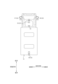
- FIG. 1 is a side view of a vehicle including an information processing device according to an embodiment.
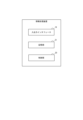
- FIG. 2 is a top view of the vehicle of FIG. 1; 2 is a block diagram showing a schematic configuration of the information processing device in FIG. 1.
- FIG. FIG. 2 is a diagram of a moving trajectory of a vehicle when turning left, viewed from vertically above, in order to explain the maximum movement portion and the minimum movement portion of the vehicle. It is a figure which shows the example of a left original image and a right original image as a support image. It is a figure which shows the example of the processed side image as a support image.
- FIG. 7 is a diagram showing an example of a processed top image as a support image.
- FIG. 7 is a diagram showing another example of a processed side image as a support image.
- FIG. 7 is a diagram showing another example of a processed top image as a support image. It is a figure which shows yet another example of a left original image and a right original image as a support image. It is a figure which shows yet another example of a processed side image as a support image. It is a figure which shows yet another example of a processed top image as a support image.
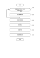
- 4 is a flowchart for explaining support image generation processing executed by the control unit in FIG. 3.
- FIG. 3 is a flowchart for explaining support image generation processing executed by the control unit in FIG. 3.
- an information processing device 10 may be mounted on a vehicle 11.
- Vehicle 11 may further include at least one camera 12, a communication device 13, and a display 14.
- the vehicle 11 may be of any type.
- the vehicle 11 is, for example, a truck, a tank lorry, a bus having a relatively long overall length, etc., which has a loading platform on the sides parallel to the front-rear direction.
- the camera 12 is provided so as to be able to image a part of the vehicle 11 as well as the scene around the vehicle 11.
- the camera 12 may provide the information processing device 10 with an image generated by imaging as information.
- the vehicle 11 in this embodiment includes a first camera 15, a second camera 16, a third camera 17, and a fourth camera 18 as at least one camera 12.
- the first camera 15 is provided, for example, so as to be able to image the scene in front of the vehicle 11.
- the second camera 16 is provided, for example, so as to be able to image the scene behind the vehicle 11.
- the third camera 17 is provided, for example, so as to be able to capture images of the left side and left rear side of the vehicle 11.
- the fourth camera 18 is provided, for example, so as to be able to capture images of the right side and right rear side of the vehicle 11.
- the optical axes of the first camera 15 to the fourth camera 18 may be perpendicular to the width direction of the vehicle 11.
- the communication device 13 may be capable of wireless communication with an external camera located near the vehicle 11.
- the external camera may be provided, for example, on a roadside machine, another vehicle, a building, or a flying object such as a drone.
- the communication device 13 may acquire from the external camera an image generated by imaging, together with the position of the external camera, as information.
- the display 14 is placed at a position that is visible from the driver's seat.
- the display 14 may display a support image generated by the information processing device 10, which will be described later.
- Display 14 may be a known type of display such as a liquid crystal display or a head-mounted display.
- the information processing device 10 generates a support image using images of the surroundings of the vehicle 11 obtained from the camera 12 and an external camera.
- the configuration of the information processing device 10 will be described below.
- the information processing device 10 includes an input/output interface (acquisition unit) 19 and a control unit 20.
- the information processing device 10 may further include a storage unit 21.
- the input/output interface 19 acquires images of the surroundings of the vehicle 11 from at least one of the camera 12 and an external camera.
- the input/output interface 19 may acquire operation information of the vehicle 11 from the vehicle 11.
- the maneuvering information may include, for example, the speed, acceleration, steering angle, etc. of the vehicle 11.
- the input/output interface 19 may provide the display 14 with a support image generated by the control unit 20, as described later.
- the storage unit 21 includes any storage device such as a RAM (Random Access Memory) and a ROM (Read Only Memory).
- the storage unit 21 may store various programs that cause the control unit 20 to function and various information that the control unit 20 uses.
- the storage unit 21 may store, for example, a specific position in a three-dimensional coordinate system whose origin is a point determined for the vehicle 11.
- the specific position is the position of the maximum movement part.
- the maximum movement portion is a portion of the outer surface of the vehicle 11 that moves with the largest radius of curvature behind the minimum movement portion, which will be described later, in the longitudinal direction of the vehicle 11 when turning left or right. It's good.
- the maximum movement portion may be a portion of the outer surface of the vehicle 11 that moves with the maximum radius of curvature behind the driver's seat of the vehicle 11 in the longitudinal direction of the vehicle 11 when turning right or left.
- the maximum movement portion is a portion having the maximum width in the height direction at the rear end in the front-rear direction on the side surface of the loading platform.
- the maximally moving portion is a portion located at the same position as the rear end of the loading platform and at an arbitrary position in the vertical direction.
- the minimum moving part is a part of the outer surface of the vehicle 11 that moves with the smallest radius of curvature when turning left or right.
- the minimum moving portion is a portion having the maximum width in the height direction at the same position as the rearmost wheel 22 in the longitudinal direction of the vehicle 11.
- the minimum moving part is at the same position as the rearmost wheel 22 and at any position in the vertical direction. It is a part.
- the storage unit 21 further stores a conversion formula or a conversion table for coordinate transformation for converting the surrounding image into a composite image.
- the control unit 20 includes one or more processors and memory.
- the processor may include a general-purpose processor that loads a specific program to execute a specific function, and a dedicated processor specialized for specific processing.
- the dedicated processor may include an application specific integrated circuit (ASIC).
- the processor may include a programmable logic device (PLD).
- the PLD may include an FPGA (Field-Programmable Gate Array).
- the control unit 20 may be either an SoC (System-on-a-Chip) or an SiP (System In-a-Package) in which one or more processors work together.
- the control unit 20 generates a support image using the surrounding images acquired by the input/output interface 19.
- the support image is an image in which the first partial image is superimposed on the second partial image.
- the support image may further include an image in which a third partial image is superimposed on the second partial image.
- the first partial image is an image that includes a mark indicating the position of the maximum movement part or a position further spread out from the position in the width direction of the vehicle 11 by a predetermined interval.
- the predetermined interval is a length that can be considered as a margin to prevent the side surface of the vehicle 11 from coming into contact with an obstacle, and is, for example, but not limited to, 10 cm.
- the predetermined interval may be arbitrarily determined by the user's designation.
- the control unit 20 may determine the predetermined interval depending on the traveling speed of the vehicle 11.
- the control unit 20 may obtain the traveling speed of the vehicle 11 and determine the predetermined interval so that the faster the traveling speed is, the larger the predetermined interval is than when the traveling speed is slow.
- the control unit 20 may determine the predetermined interval according to the weight of the cargo loaded on the loading platform.
- the control unit 20 may obtain the weight of the cargo from a weight sensor attached to the cargo platform, and determine the predetermined interval so that the heavier the cargo, the larger the predetermined interval is compared to the lighter the cargo.
- the control unit 20 may determine the predetermined interval depending on the overall length of the vehicle 11, in other words, the length in the longitudinal direction.
- the control unit 20 calculates the total length of the vehicle 11 from the image captured by the third camera 17 or the fourth camera 18, and sets a predetermined interval so that the longer the total length of the vehicle 11 is, the larger the length is compared to the shorter the total length of the vehicle 11. You may decide.
- the second partial image is an image of the vehicle 11 on which the information processing device 10 is mounted, which is included in the surrounding image.
- the second partial image may include an image of at least a portion of the vehicle 11.
- the third partial image is an image including a mark indicating the position of the minimum movement part or a position further spread out from the position at a predetermined interval in the width direction of the vehicle 11.
- the support image may be an image of the vehicle 11 viewed from a specific viewpoint with the vehicle 11 as a reference.
- the support image may be a single image or may include multiple images.
- the support image may include, for example, a side view image and a top view image.
- the side display image is an image that includes the side surface of the vehicle 11 as a second partial image.
- the top display image is, for example, an image that includes the top surface of the vehicle 11 as a partial image, such as an image of the vehicle 11 viewed from above.
- an image viewed from a viewpoint above the rear side or above the front side of the vehicle 11 may include a side display image and a top display image.
- the type of image, such as a side view image, to be included in the support image may be predetermined or may be selected later.
- the support image may be generated by superimposing visual information on the surrounding image acquired by the input/output interface 19.
- the side display image included in the support image includes a left original image lri generated by imaging by the third camera 17 and a right original image rri generated by imaging by the fourth camera 18. That's fine.
- the second partial image pi2 which is an image of the vehicle 11
- the first partial image pi1 which is an image of a landmark indicating the maximum movement part
- the minimum A third partial image pi3, which is an image of a landmark indicating a moving part, is superimposed.
- the mark indicating the part may be linear, but it may also be any one point included in the line, and it may be a plurality of discrete marks. It may be a point.
- the support image may be generated by superimposing visual information on an image that is processed based on the surrounding image.
- An image processed based on surrounding images may be generated by performing coordinate transformation on a single surrounding image, or may be generated by combining multiple surrounding images and performing coordinate transformation as necessary. It may be generated by
- the support image generated by the control unit 20 may be viewed from a position away from the vehicle 11.
- the control unit 20 may process the side display image by processing at least one of the surrounding image generated by the third camera 17 or the fourth camera 18 and the image captured by the external camera, or by combining both. May be generated.
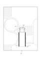
- the side display image generated by the control unit 20 may be a processed side view image psi, which is a converted image with the viewpoint vertically above the vehicle 11.
- the processed side image psi includes a second partial image pi2 which is an image of the vehicle 11, a first partial image pi1 which is an image of a landmark indicating the maximum movement part, and a third partial image pi1 which is an image of a landmark indicating the minimum movement part.
- the partial image pi3 of is superimposed.
- the mark indicating the part may be linear, but it may also be any one point included in the line, and it may be a plurality of discrete marks. It may be a point.
- the top display image generated by the control unit 20 may be a processed top image Pti that is a converted image with the viewpoint vertically above the vehicle 11. Also in the processed top image pti, the first partial image pi1 and the third partial image pi3 are superimposed on the second partial image pi2.
- the support image may be a viewpoint image that includes a partial image spi of a curb located near the vehicle 11.
- the control unit 20 may determine the position of the viewpoint so that the partial image spi of the curb is included in the support image.
- the viewpoint and angle of view are set in the left original image lri, right original image rri, processed side image psi, and processed top image pti described above so that the partial image spi of the curb is included.
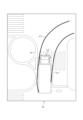
- the first partial image pi1 may include a trajectory of future movement of the above-mentioned landmark as the vehicle 11 travels.
- the first partial image pi1 showing the trajectory of the landmark is planar.
- the first partial image pi1 showing the trajectory of the landmark is planar, as shown in FIG.
- the first partial image pi1 showing the locus of the landmark is linear, as shown in FIG.
- Partial image pi3 has a curved surface shape.
- the first partial image pi1 and the third partial image pi3 showing the locus of the landmark are It is in a state of
- the vehicle 11 turns right in a configuration in which the support image is the processed top image pti, as shown in FIG. 13, the first partial image pi1 and the third partial image pi3 showing the locus of the landmark It is.
- the control unit 20 may prioritize the third partial image pi3 over the first partial image pi1 and superimpose it on the second partial image pi2 on the turning direction side of the vehicle 11 in the left-right direction. For example, the control unit 20 may superimpose only the third partial image pi3 on the turning direction side of the vehicle 11 in the left-right direction. Further, the control unit 20 may prioritize the first partial image pi1 over the third partial image pi3 and superimpose it on the second partial image pi2 on the side opposite to the turning direction in the left-right direction of the vehicle 11. For example, the control unit 20 may superimpose only the first partial image pi1 on the side opposite to the turning direction in the left-right direction of the vehicle 11.
- the control unit 20 calculates the trajectory of the landmark based on the steering angle and speed of the vehicle 11, and creates a first partial image pi1 and a third partial image pi3. good. If there is a possibility that the vehicle body is tilted when the vehicle 11 turns right or left, the control unit 20 calculates the locus of the tilted mark and creates a first partial image pi1 and a third partial image pi3. You may do so.
- the trajectory of the landmark may be the entire trajectory of the vehicle 11 from the start to the end of the right turn or left turn, or may be a partial trajectory. Depending on the progress of the right turn or left turn of the vehicle 11, the trajectory that has already been passed may be deleted or may remain displayed. When the steering angle or speed of the vehicle 11 changes, the control unit 20 may recalculate the trajectory of the landmark and create a new first partial image pi1 and third partial image pi3.
- the control unit 20 may determine whether or not the obstacle intersects with the trajectory of the landmark.
- the support image may be created as an image from a viewpoint that includes a partial image of the obstacle. Obstacles include, for example, pedestrians around the vehicle 11, other vehicles, signboards, curved mirrors, signs, and the like.
- the intersection of the trajectory of the obstacle and the landmark causes the position corresponding to the landmark to overlap with the position of the obstacle in real space. In other words, the intersection between the obstacle and the trajectory of the landmark may cause the vehicle 11 to collide with the obstacle during a right or left turn in a configuration where the landmark is a part of the vehicle body of the vehicle 11.
- the control unit 20 may include a warning display or the like in the support image when the obstacle intersects with the trajectory of the landmark.
- the warning display may include a change in the display form of the partial image of the obstacle or the trajectory of the landmark.
- the change in display format may include changing the displayed color, blinking, and the like.
- the control unit 20 may emit a warning sound from the speaker instead of or simultaneously with the warning display or the like.
- the control unit 20 may highlight all or part of the outer edge of the partial image of the obstacle included in the support image, or may display an image showing the position of the obstacle.
- the control unit 20 determines whether or not an obstacle exists on the side in the traveling direction of the vehicle 11 from the surrounding image acquired by the input/output interface 19 when turning right or left, and only when an obstacle exists, changes the landmark.
- the trajectory may be displayed on the display 14.
- the control unit 20 may apply the support image generated as described above to the display 14 and display it.
- the support image generation process starts periodically, for example, in accordance with the cycle of acquiring surrounding images from the camera 12 and an external camera.
- step S100 the control unit 20 determines whether the support image includes a type of image that requires processing based on surrounding images. If so, the process proceeds to step S101. If not, the process proceeds to step S102.
- step S101 the control unit 20 processes the surrounding image to generate an image on which the first partial image pi1 is superimposed. After generation, the process proceeds to step S102.
- step S102 the control unit 20 recognizes the latest driving state based on the driving information recently acquired from the vehicle 11. After recognition, the process proceeds to step S103.
- step S103 the control unit 20 determines the movement trajectory of the landmark in the image coordinate system for each type of image included in the support image, based on the specific position stored in the storage unit 21 and the maneuvering state recognized in step S102. Calculate. After the calculation, the process proceeds to step S104.
- step S104 if there is an obstacle on the side in the traveling direction of the vehicle 11, the control unit 20 determines whether or not the obstacle intersects with the trajectory of the landmark calculated in step S103. . After the determination, the process proceeds to step S105.
- step S105 the control unit 20 provides support by superimposing the first partial image pi1 and the third partial image pi3, which are the trajectories calculated in step S103, on the image for superimposing the first partial image pi1. Generate an image. Further, the control unit 20 adds an image effect such as blinking to the support image to clearly indicate the obstacle determined to intersect with the trajectory in step S104. Further, the control unit 20 applies the generated support image to the display 14 and causes it to be displayed. After the support image is generated, the support image generation process ends.
- the information processing device 10 of the present embodiment configured as described above has a maximum radius of curvature that moves behind the minimum moving part of the outer surface of the vehicle 11 that moves with the smallest radius of curvature when turning left or right.
- a support image in which a first partial image pi1 including a mark indicating the position of the moving part is superimposed on a second partial image pi2 of the vehicle 11 is generated using surrounding images.
- the information processing device 10 of the present embodiment determines the position of the maximum movement portion that moves with the maximum radius of curvature behind the minimum movement portion that moves with the minimum radius of curvature when turning left or right on the outer surface of the vehicle 11.
- a support image in which a first partial image pi1 including a mark indicating a position further spread out at a predetermined interval in the width direction of the vehicle is superimposed on a second partial image pi2 of the vehicle 11 is created using surrounding images. and generate it.
- the information processing device 10 allows the driver to see the maximum movement part that moves with the maximum radius of curvature behind the minimum movement part when making a turn, thereby reducing the possibility of a collision.
- the information processing device 10 of the present embodiment may be located behind the driver's seat, and on the outer surface of the vehicle 11, relative to the position of the maximally moving portion of the vehicle 11 that moves with the maximum radius of curvature when turning left or right.
- the first partial image pi1 which includes a mark indicating a position further widened at a predetermined interval in the width direction, or a mark indicating a position further widened at a predetermined interval in the width direction of the vehicle, is transferred to a second partial image pi1 of the vehicle 11.
- a support image superimposed on the partial image pi2 is generated using surrounding images.
- the first partial image pi1 includes a locus of future movement of the landmark as the vehicle 11 travels.
- the information processing device 10 can more easily make visible a passage route that is wider than the trajectory taken by the driver's seat behind the driver's seat, which is difficult to grasp when making a turn. Therefore, the information processing device 10 can further reduce the possibility of collision.
- the information processing device 10 of the present embodiment determines whether the landmark intersects with the obstacle on the assumption that the vehicle 11 is turning left or right. With such a configuration, the information processing device 10 can make the driver clearly aware of the possibility of a collision between the vehicle 11 and an obstacle.
- the support image has a side display image that includes the side surface of the vehicle 11 as a second partial image.
- the side of the vehicle 11 may pass through a position that is more protruding than the front wheels, resulting in a collision with an object located on the side of the vehicle 11. there is a possibility.
- the information processing device 10 having the above configuration allows the driver to visually check the side of the vehicle 11, thereby further reducing the possibility of a collision.
- the support image includes a partial image spi of a curb located near the vehicle 11.
- the information processing device 10 can reduce the possibility of running onto a curb or colliding with a curb when turning right or left.
- the predetermined interval is determined based on the traveling speed of the vehicle 11 or the length of the vehicle 11 in the longitudinal direction. If the traveling speed of the vehicle 11 is high, there is a high possibility that the vehicle body will tilt significantly when turning right or left. For example, when the traveling speed is fast, the predetermined interval may be made larger than when the traveling speed is slow. Furthermore, if the body of the vehicle 11 is long in the longitudinal direction, it becomes more difficult for the vehicle 11 to turn right or left. For example, when the length of the vehicle body is long, the predetermined interval may be made larger than when the length of the vehicle body is short. With such a configuration, the information processing device 10 can avoid contact between the body of the vehicle 11 and an obstacle.
- the predetermined interval is determined based on the weight of the luggage loaded on the platform. If the weight of the luggage loaded on the loading platform of the vehicle 11 is heavy, there is a high possibility that the vehicle body will tilt significantly when turning right or left. For example, if the load is heavy, the predetermined interval may be made larger than if it is light. With such a configuration, the information processing device 10 can avoid contact between the body of the vehicle 11 and an obstacle.
- the information processing device an acquisition unit that acquires an image of the surroundings of the vehicle from at least one camera; A first partial image including a mark indicating the position of a maximum movement part that moves with a maximum radius of curvature behind a minimum movement part that moves with a minimum radius of curvature when turning left or right on the outer surface of the vehicle, A control unit that uses the surrounding image to generate a support image superimposed on a second partial image that includes an image of at least a portion of the vehicle.
- the information processing device an acquisition unit that acquires an image of the surroundings of the vehicle from at least one camera; On the outer surface of the vehicle, at a predetermined interval in the width direction of the vehicle from the position of the maximum movement part that moves with the maximum radius of curvature behind the minimum movement part that moves with the minimum radius of curvature when turning left or right. a control unit that uses the surrounding images to generate a support image in which a first partial image including a mark indicating the expanded position is superimposed on a second partial image including an image of at least a portion of the vehicle; Equipped with.
- the information processing device an acquisition unit that acquires an image of the surroundings of a vehicle having a driver's seat from at least one camera; The position of a maximally moving part that is rearward of the driver's seat and moves with the maximum radius of curvature when turning right or left on the outer surface of the vehicle, or further at a predetermined interval in the width direction of the vehicle from the position.
- a control unit that uses the surrounding images to generate a support image in which a first partial image including a mark indicating the expanded position is superimposed on a second partial image including an image of at least a part of the vehicle; Equipped with.
- the first partial image includes a trajectory of future movement of the landmark as the vehicle travels.
- the control unit determines whether or not the landmark intersects with the obstacle during the course of the vehicle turning right or left, when the obstacle is located on the side in the traveling direction of the vehicle.
- the vehicle is a truck with a loading platform
- the minimum moving part is a part having the maximum width at the same position as the rearmost wheel of the vehicle
- the maximum movement portion is a portion having the maximum width at the rear end in the front-rear direction on the side surface of the loading platform.
- the support image includes a side display image that includes a side surface of the vehicle as the second partial image.
- the side display image is an image viewed vertically above the vehicle.
- the support image includes a partial image of a curb located near the vehicle.
- the support image includes a top display image in which the vehicle is viewed from above.
- the control unit determines the predetermined interval based on the traveling speed of the vehicle or the longitudinal length of the vehicle.
- the vehicle is a truck with a loading platform
- the control unit determines the predetermined interval based on the weight of the luggage loaded on the platform.
- the embodiment of the information processing device 10 has been described above, but the embodiment of the present disclosure includes a method or a program for implementing the device, as well as a storage medium (for example, an optical disk, a magneto-optical disk, etc.) on which the program is recorded. It is also possible to take an embodiment as a disk, CD-ROM, CD-R, CD-RW, magnetic tape, hard disk, memory card, etc.).
- the implementation form of a program is not limited to an application program such as an object code compiled by a compiler or a program code executed by an interpreter, but may also be in the form of a program module incorporated into an operating system. good.
- the program may or may not be configured such that all processing is performed only in the CPU on the control board.
- the program may be configured such that part or all of the program is executed by an expansion board attached to the board or another processing unit mounted in an expansion unit, as necessary.
- the landmark included in the first partial image pi1 is a support image that indicates the position of the maximum movement portion of the vehicle 11, but is not limited to this.
- an assistance image may be generated in which the mark included in the first partial image pi1 indicates an arbitrary position specified by the user on the outer edge of the vehicle 11.
- embodiments according to the present disclosure are not limited to any of the specific configurations of the embodiments described above. Embodiments of the present disclosure extend to any novel features or combinations thereof described in this disclosure, or to any novel methods or process steps or combinations thereof described. be able to.
- descriptions such as “first” and “second” are identifiers for distinguishing the configurations.
- the numbers in the configurations can be exchanged.
- a first camera can exchange identifiers "first” and “second” with a second camera. The exchange of identifiers takes place simultaneously.
- the configurations are distinguished. Identifiers may be removed. Configurations with removed identifiers are distinguished by codes.
- the description of identifiers such as “first” and “second” in this disclosure should not be used to interpret the order of the configuration or to determine the existence of lower-numbered identifiers.
Landscapes
- Engineering & Computer Science (AREA)
- Multimedia (AREA)
- Mechanical Engineering (AREA)
- Physics & Mathematics (AREA)
- General Physics & Mathematics (AREA)
- Theoretical Computer Science (AREA)
- Human Computer Interaction (AREA)
- Acoustics & Sound (AREA)
- Traffic Control Systems (AREA)
- Closed-Circuit Television Systems (AREA)
Abstract
Description
車両に搭載される情報処理装置であって、
前記車両の周囲の画像を、少なくとも1つのカメラから取得する取得部と、
前記車両の外表面の中で、右左折に際して最小の曲率半径で移動する最小移動部分よりも後方において最大の曲率半径で移動する極大移動部分の位置を示す目印を含む第1の部分像を、前記車両の少なくとも一部の像を含む第2の部分像に重畳した支援画像を、前記周囲の画像を用いて生成する制御部と、を備える。
車両の周囲の画像を、少なくとも1つのカメラから取得する取得部と、
前記車両の外表面の中で、右左折に際して最小の曲率半径で移動する最小移動部分よりも後方において最大の曲率半径で移動する極大移動部分の位置を示す目印を含む第1の部分像を、前記車両の少なくとも一部の像を含む第2の部分像に重畳した支援画像を、前記周囲の画像を用いて生成する制御部と、を備える。
車両の周囲の画像を、少なくとも1つのカメラから取得する取得部と、
前記車両の外表面の中で、右左折に際して最小の曲率半径で移動する最小移動部分よりも後方において最大の曲率半径で移動する極大移動部分の位置よりも該車両の幅方向に所定の間隔で広げた位置を示す目印を含む第1の部分像を、前記車両の少なくとも一部の像を含む第2の部分像に重畳した支援画像を、前記周囲の画像を用いて生成する制御部と、を備える。
運転席を有する車両の周囲の画像を、少なくとも1つのカメラから取得する取得部と、
前記運転席よりも後方であって、前記車両の外表面の中で右左折に際して最大の曲率半径で移動する極大移動部分の位置、又は該位置よりも該車両の幅方向に所定の間隔で更に広げた位置を示す目印を含む第1の部分像を、前記車両の少なくとも一部の像を含む第2の部分像に重畳した支援画像を、前記周囲の画像を用いて生成する制御部と、を備える。
前記第1の部分像は、前記車両の走行に伴う前記目印の将来の移動の軌跡を含む。
前記制御部は、前記車両の進行方向の側方に障害物が位置する場合、前記車両の右左折の過程で前記目印が前記障害物と交差するか否かを判別する。
前記車両は、荷台を有するトラックであり、
前記最小移動部分は、前記車両の最後尾の車輪と同じ位置における最大幅を有する部分であり、
前記極大移動部分は、前記荷台の側面における前後方向の後端で最大幅を有する部分である。
前記支援画像は、前記車両の側面を前記第2の部分像として含む側面表示画像を有する。
前記側面表示画像は、前記車両よりも鉛直上方を視点とした画像である。
前記支援画像には、前記車両近傍に位置する縁石の部分画像が含まれる。
前記支援画像は、前記車両を上面視した上面表示画像を有する。
前記制御部は、前記車両の走行速度、又は前記車両の前後方向の長さに基づいて、前記所定の間隔を決定する。
前記車両は、荷台を有するトラックであり、
前記制御部は、前記荷台に積載された荷物の重さに基づいて前記所定の間隔を決定する。
11 車両
12 カメラ
13 通信装置
14 ディスプレイ
15 第1のカメラ
16 第2のカメラ
17 第3のカメラ
18 第4のカメラ
19 入出力インタフェース(取得部)
20 制御部
21 記憶部
22 最後尾の車輪
lri 左原画像
pi1 第1の部分像
pi2 第2の部分像
pi3 第3の部分像
psi 加工側面画像
pti 加工上面画像
rri 右原画像
spi 縁石の部分画像
Claims (12)
- 車両の周囲の画像を、少なくとも1つのカメラから取得する取得部と、
前記車両の外表面の中で、右左折に際して最小の曲率半径で移動する最小移動部分よりも後方において最大の曲率半径で移動する極大移動部分の位置を示す目印を含む第1の部分像を、前記車両の少なくとも一部の像を含む第2の部分像に重畳した支援画像を、前記周囲の画像を用いて生成する制御部と、を備える
情報処理装置。 - 車両の周囲の画像を、少なくとも1つのカメラから取得する取得部と、
前記車両の外表面の中で、右左折に際して最小の曲率半径で移動する最小移動部分よりも後方において最大の曲率半径で移動する極大移動部分の位置よりも該車両の幅方向に所定の間隔で広げた位置を示す目印を含む第1の部分像を、前記車両の少なくとも一部の像を含む第2の部分像に重畳した支援画像を、前記周囲の画像を用いて生成する制御部と、を備える
情報処理装置。 - 運転席を有する車両の周囲の画像を、少なくとも1つのカメラから取得する取得部と、
前記運転席よりも後方であって、前記車両の外表面の中で右左折に際して最大の曲率半径で移動する極大移動部分の位置、又は該位置よりも該車両の幅方向に所定の間隔で更に広げた位置を示す目印を含む第1の部分像を、前記車両の少なくとも一部の像を含む第2の部分像に重畳した支援画像を、前記周囲の画像を用いて生成する制御部と、を備える
情報処理装置。 - 請求項1から3のいずれか1項に記載の情報処理装置において、
前記第1の部分像は、前記車両の走行に伴う前記目印の将来の移動の軌跡を含む
情報処理装置。 - 請求項1から4のいずれか1項に記載の情報処理装置において、
前記制御部は、前記車両の進行方向の側方に障害物が位置する場合、前記車両の右左折の過程で前記目印が前記障害物と交差するか否かを判別する
情報処理装置。 - 請求項1又は2に記載の情報処理装置において、
前記車両は、荷台を有するトラックであり、
前記最小移動部分は、前記車両の最後尾の車輪と同じ位置における最大幅を有する部分であり、
前記極大移動部分は、前記荷台の側面における前後方向の後端で最大幅を有する部分である
情報処理装置。 - 請求項1から6のいずれか1項に記載の情報処理装置において、
前記支援画像は、前記車両の側面を前記第2の部分像として含む側面表示画像を有する
情報処理装置。 - 請求項7に記載の情報処理装置において、
前記側面表示画像は、前記車両よりも鉛直上方を視点とした画像である
情報処理装置。 - 請求項1から8のいずれか1項に記載の情報処理装置において、
前記支援画像には、前記車両近傍に位置する縁石の部分画像が含まれる
情報処理装置。 - 請求項1から9のいずれか1項に記載の情報処理装置において、
前記支援画像は、前記車両を上面視した上面表示画像を有する
情報処理装置。 - 請求項2に記載の情報処理装置において、
前記制御部は、前記車両の走行速度、又は前記車両の前後方向の長さに基づいて、前記所定の間隔を決定する
情報処理装置。 - 請求項2に記載の情報処理装置において、
前記車両は、荷台を有するトラックであり、
前記制御部は、前記荷台に積載された荷物の重さに基づいて前記所定の間隔を決定する
情報処理装置。
Priority Applications (1)
| Application Number | Priority Date | Filing Date | Title |
|---|---|---|---|
| US18/862,874 US20250353435A1 (en) | 2022-05-06 | 2023-05-01 | Information processing device |
Applications Claiming Priority (2)
| Application Number | Priority Date | Filing Date | Title |
|---|---|---|---|
| JP2022-076739 | 2022-05-06 | ||
| JP2022076739A JP7756047B2 (ja) | 2022-05-06 | 2022-05-06 | 情報処理装置 |
Publications (1)
| Publication Number | Publication Date |
|---|---|
| WO2023214566A1 true WO2023214566A1 (ja) | 2023-11-09 |
Family
ID=88646500
Family Applications (1)
| Application Number | Title | Priority Date | Filing Date |
|---|---|---|---|
| PCT/JP2023/017072 Ceased WO2023214566A1 (ja) | 2022-05-06 | 2023-05-01 | 情報処理装置 |
Country Status (3)
| Country | Link |
|---|---|
| US (1) | US20250353435A1 (ja) |
| JP (1) | JP7756047B2 (ja) |
| WO (1) | WO2023214566A1 (ja) |
Citations (6)
| Publication number | Priority date | Publication date | Assignee | Title |
|---|---|---|---|---|
| JP2002133597A (ja) * | 2000-10-23 | 2002-05-10 | Isuzu Motors Ltd | バックミラー装置 |
| WO2007000868A1 (ja) * | 2005-06-27 | 2007-01-04 | Aisin Seiki Kabushiki Kaisha | 障害物検出装置 |
| JP2012061989A (ja) * | 2010-09-17 | 2012-03-29 | Fujitsu Ten Ltd | 画像処理装置、及び、画像処理方法 |
| JP2016107985A (ja) * | 2014-12-05 | 2016-06-20 | メクラ・ラング・ゲーエムベーハー・ウント・コー・カーゲーMEKRA Lang GmbH & Co. KG | ビジュアルシステム |
| EP3321130A1 (de) * | 2016-09-07 | 2018-05-16 | Continental Automotive GmbH | Verfahren zur nachführung eines bildausschnitts |
| JP2019046086A (ja) * | 2017-08-31 | 2019-03-22 | アイシン精機株式会社 | 周辺監視装置 |
Family Cites Families (10)
| Publication number | Priority date | Publication date | Assignee | Title |
|---|---|---|---|---|
| JP3372190B2 (ja) * | 1997-07-17 | 2003-01-27 | 富士重工業株式会社 | 車両の衝突防止装置 |
| JP2001167380A (ja) * | 1999-12-07 | 2001-06-22 | Toshiba Corp | 道路監視装置 |
| JP4792889B2 (ja) * | 2005-09-21 | 2011-10-12 | トヨタ自動車株式会社 | 車両用運転支援装置 |
| JP2009157490A (ja) * | 2007-12-25 | 2009-07-16 | Honda Motor Co Ltd | 車両の運転支援装置 |
| JP2011118485A (ja) * | 2009-11-30 | 2011-06-16 | Fujitsu Ten Ltd | 方向転換支援装置及び方法 |
| JP5729641B2 (ja) * | 2011-04-01 | 2015-06-03 | いすゞ自動車株式会社 | 車両用警報装置 |
| EP2830031A4 (en) * | 2012-03-19 | 2016-08-10 | Toyota Motor Co Ltd | DEVICE FOR SUPPORTING COLLISION PREVENTION |
| JP2019137367A (ja) * | 2018-02-15 | 2019-08-22 | アイシン・エィ・ダブリュ株式会社 | 運転支援システムおよび運転支援プログラム |
| JP7279674B2 (ja) * | 2020-03-26 | 2023-05-23 | いすゞ自動車株式会社 | 車両位置描画システム |
| JP2021157501A (ja) * | 2020-03-27 | 2021-10-07 | いすゞ自動車株式会社 | 車両位置描画システム |
-
2022
- 2022-05-06 JP JP2022076739A patent/JP7756047B2/ja active Active
-
2023
- 2023-05-01 US US18/862,874 patent/US20250353435A1/en active Pending
- 2023-05-01 WO PCT/JP2023/017072 patent/WO2023214566A1/ja not_active Ceased
Patent Citations (6)
| Publication number | Priority date | Publication date | Assignee | Title |
|---|---|---|---|---|
| JP2002133597A (ja) * | 2000-10-23 | 2002-05-10 | Isuzu Motors Ltd | バックミラー装置 |
| WO2007000868A1 (ja) * | 2005-06-27 | 2007-01-04 | Aisin Seiki Kabushiki Kaisha | 障害物検出装置 |
| JP2012061989A (ja) * | 2010-09-17 | 2012-03-29 | Fujitsu Ten Ltd | 画像処理装置、及び、画像処理方法 |
| JP2016107985A (ja) * | 2014-12-05 | 2016-06-20 | メクラ・ラング・ゲーエムベーハー・ウント・コー・カーゲーMEKRA Lang GmbH & Co. KG | ビジュアルシステム |
| EP3321130A1 (de) * | 2016-09-07 | 2018-05-16 | Continental Automotive GmbH | Verfahren zur nachführung eines bildausschnitts |
| JP2019046086A (ja) * | 2017-08-31 | 2019-03-22 | アイシン精機株式会社 | 周辺監視装置 |
Also Published As
| Publication number | Publication date |
|---|---|
| JP2023165550A (ja) | 2023-11-16 |
| JP7756047B2 (ja) | 2025-10-17 |
| US20250353435A1 (en) | 2025-11-20 |
Similar Documents
| Publication | Publication Date | Title |
|---|---|---|
| EP3915857B1 (en) | A parking assist apparatus and a method of controlling the parking assist apparatus | |
| JP6531832B2 (ja) | 駐車スペース検出方法および装置 | |
| EP3367364B1 (en) | Parking support information display method and parking support device | |
| KR102205144B1 (ko) | 주차 지원 방법 및 주차 지원 장치 | |
| US20260042348A1 (en) | Display control device | |
| CN108140312A (zh) | 停车辅助方法及停车辅助装置 | |
| CA3002639A1 (en) | Parking space line detection method and device | |
| US11601621B2 (en) | Vehicular display system | |
| JP7342926B2 (ja) | 表示制御装置及び表示制御プログラム | |
| JP5516988B2 (ja) | 駐車支援装置 | |
| JP5067169B2 (ja) | 車両用駐車支援装置および画像表示方法 | |
| JP2009248765A (ja) | 駐車支援装置および駐車支援方法 | |
| JP6595647B2 (ja) | 走行制御装置、車両および走行制御方法 | |
| JP7296899B2 (ja) | 車両用制御装置 | |
| JP7399312B2 (ja) | 車両制御装置 | |
| WO2021161378A1 (ja) | 駐車支援方法及び駐車支援装置 | |
| JP7452479B2 (ja) | 表示制御装置 | |
| CN115257726A (zh) | 车辆控制的方法、装置、车辆和存储介质 | |
| WO2023214566A1 (ja) | 情報処理装置 | |
| JP2022189118A (ja) | 車両用表示装置、表示方法及びプログラム | |
| JP7790279B2 (ja) | 車載表示装置 | |
| JP7703100B2 (ja) | 運転支援装置、運転支援方法、およびプログラム | |
| US20220086368A1 (en) | Vehicular display system | |
| JP2013184491A (ja) | 車両走行支援装置 | |
| US20260021824A1 (en) | Risk presentation apparatus and, risk presentation method |
Legal Events
| Date | Code | Title | Description |
|---|---|---|---|
| 121 | Ep: the epo has been informed by wipo that ep was designated in this application |
Ref document number: 23799495 Country of ref document: EP Kind code of ref document: A1 |
|
| WWE | Wipo information: entry into national phase |
Ref document number: 18862874 Country of ref document: US |
|
| NENP | Non-entry into the national phase |
Ref country code: DE |
|
| 122 | Ep: pct application non-entry in european phase |
Ref document number: 23799495 Country of ref document: EP Kind code of ref document: A1 |
|
| WWP | Wipo information: published in national office |
Ref document number: 18862874 Country of ref document: US |