WO2023210548A1 - 煙検知装置 - Google Patents
煙検知装置 Download PDFInfo
- Publication number
- WO2023210548A1 WO2023210548A1 PCT/JP2023/016019 JP2023016019W WO2023210548A1 WO 2023210548 A1 WO2023210548 A1 WO 2023210548A1 JP 2023016019 W JP2023016019 W JP 2023016019W WO 2023210548 A1 WO2023210548 A1 WO 2023210548A1
- Authority
- WO
- WIPO (PCT)
- Prior art keywords
- light
- section
- light receiving
- light emitting
- receiving section
- Prior art date
- Legal status (The legal status is an assumption and is not a legal conclusion. Google has not performed a legal analysis and makes no representation as to the accuracy of the status listed.)
- Ceased
Links
Images


Classifications
-
- G—PHYSICS
- G01—MEASURING; TESTING
- G01N—INVESTIGATING OR ANALYSING MATERIALS BY DETERMINING THEIR CHEMICAL OR PHYSICAL PROPERTIES
- G01N21/00—Investigating or analysing materials by the use of optical means, i.e. using sub-millimetre waves, infrared, visible or ultraviolet light
- G01N21/84—Systems specially adapted for particular applications
- G01N21/88—Investigating the presence of flaws or contamination
- G01N21/95—Investigating the presence of flaws or contamination characterised by the material or shape of the object to be examined
- G01N21/954—Inspecting the inner surface of hollow bodies, e.g. bores
-
- G—PHYSICS
- G08—SIGNALLING
- G08B—SIGNALLING OR CALLING SYSTEMS; ORDER TELEGRAPHS; ALARM SYSTEMS
- G08B17/00—Fire alarms; Alarms responsive to explosion
- G08B17/10—Actuation by presence of smoke or gases, e.g. automatic alarm devices for analysing flowing fluid materials by the use of optical means
- G08B17/103—Actuation by presence of smoke or gases, e.g. automatic alarm devices for analysing flowing fluid materials by the use of optical means using a light emitting and receiving device
- G08B17/107—Actuation by presence of smoke or gases, e.g. automatic alarm devices for analysing flowing fluid materials by the use of optical means using a light emitting and receiving device for detecting light-scattering due to smoke
Definitions
- the present invention relates to a device for detecting smoke.
- a smoke detection device that detects the occurrence of smoke in a monitored space by detecting smoke contained in the monitored space.
- One type of smoke detection device is a type called a photoelectric type.
- a photoelectric smoke detection device generates smoke particles when the light emitting part is reflected by smoke particles in the air flowing from the outside into a container that houses the light emitting part and the light receiving part. Smoke detection is performed based on the signal.
- a dual-receiver type smoke detection device emits polarized light from a light emitting part in the direction of the light emitting axis, and detects smoke in the air based on signals generated by two light receiving parts that have light receiving axes that intersect with the light emitting axis from different directions. Determine the type.
- Patent Document 1 An example of a patent document disclosing a two-light receiving type smoke detection device is Patent Document 1.
- a photoelectric smoke detection device detects smoke particles in the air flowing from a monitored space into a container that forms a smoke detection space.
- the air flowing into the container contains dust, and some of this dust adheres to the inside of the container as dirt.
- Some of the dirt adheres to the light emitting part or the light receiving part, and blocks or reflects part of the light emitted from the light emitting part.
- some of the dirt adheres to the inner wall of the container and the structures inside the container, and the light emitted from the light emitting part and reflected by particles in the air is further reflected. As a result, the accuracy of smoke detection by the smoke detection device is reduced.
- an object of the present invention is to provide a means for determining the degree of contamination inside a container in a dual-light receiving type smoke detection device.
- the present invention provides a first light emitting section that emits polarized light, a first light receiving section having a first light receiving axis that intersects with a light emitting axis of the first light emitting section, and a first light receiving section that emits polarized light.
- a second light-receiving section having a second light-receiving axis that intersects with the light-emitting axis of and is in a direction different from the first light-receiving axis; a signal generated by the first light-receiving section while the first light-emitting section is emitting light; a smoke determining section that determines the type of smoke in the air based on a signal generated by the second light receiving section while the light emitting section is emitting light; a second light emitting section that emits non-polarized light; and a second light emitting section that emits light.
- a smoke detection device including a contamination determining section that determines the degree of contamination of a smoke detector.
- the inside of the container can be detected with higher accuracy compared to a smoke detection device that does not include the second light emitting section.
- the degree of contamination can be seen.
- FIG. 1 is a diagram schematically showing the configuration of a smoke detection device according to an embodiment.
- FIG. 7 is a diagram schematically showing the configuration of a smoke detection device according to a modified example.
- FIG. 7 is a diagram schematically showing the configuration of a smoke detection device according to a modified example.
- FIG. 7 is a diagram schematically showing the configuration of a smoke detection device according to a modified example.
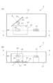
- FIG. 1 is a diagram schematically showing the configuration of a smoke detection device 1. As shown in FIG. However, in FIG. 1, illustration of components not related to the features of the present invention is omitted.
- FIG. 1(A) is a plan view of the smoke detection device 1 with the lid of the container removed.
- FIG. 1(B) is a view of the cross section indicated by the broken line in FIG. 1(A) as viewed in the direction of arrow A.
- the smoke detection device 1 includes a first light emitting section 11, a first light receiving section 12, a second light receiving section 13, a second light emitting section 14, a first electronic circuit board 15, a second electronic circuit board 16, a container 17, and a light shielding member 18. Equipped with Further, the smoke detection device 1 includes a smoke determination section (not shown) and a contamination determination section (not shown).
- the first light emitting unit 11 emits polarized light in the direction of the light emitting axis indicated by arrow B in FIG.
- the first light receiving section 12 is arranged on the first electronic circuit board 15.
- the first light receiving section 12 receives light directed in the direction of the first light receiving axis indicated by arrow C in FIG. 1(B), and generates a signal indicating the intensity of the received light.
- the first light-receiving axis is an axis that intersects the light-emitting axis of the first light-emitting section 11 at a predetermined angle within a vertical plane (a surface perpendicular to the horizontal plane) that includes the light-emitting axis of the first light-emitting section 11 .
- the second light receiving section 13 is arranged on the second electronic circuit board 16.
- the second light receiving section 13 receives light directed in the direction of the second light receiving axis indicated by arrow D in FIG. 1(A), and generates a signal indicating the intensity of the received light.
- the second light receiving axis is an axis that intersects the light emitting axis of the first light emitting section 11 at a predetermined angle within a horizontal plane that includes the light emitting axis of the first light emitting section 11 .
- the angle between the light emitting axis of the first light emitting section 11 and the first light receiving axis of the first light receiving section 12 and the angle between the light emitting axis of the first light emitting section 11 and the second light receiving axis of the second light receiving section 13 may be the same or different.
- the second light emitting section 14 is arranged on the first electronic circuit board 15.
- the second light emitting unit 14 emits non-polarized light for determining the degree of contamination within the container 17.
- the light emitted by the second light emitting section 14 is directed toward a wide area within the container 17 including the smoke detection area.
- the smoke determination section detects smoke based on the intensity of a signal generated by the first light receiving section 12, for example, during a period when the first light emitting section 11 is emitting light and the second light emitting section 14 is not emitting light. Determine the presence or absence of.
- the smoke determination section also detects a signal generated by the first light receiving section 12 and a signal generated by the second light receiving section 13 during a period when the first light emitting section 11 is emitting light and the second light emitting section 14 is not emitting light. The type of smoke is determined based on the
- the contamination determining section (not shown) detects the signal generated by the first light receiving section 12 and the second light receiving section 13 during a period when the first light emitting section 11 is not emitting light and the second light emitting section 14 is emitting light.
- the degree of contamination in the container 17 is determined based on at least one of the signals generated by the container 17. For example, the stain determination section performs the following determination.
- the intensity of the signal generated by the first light receiving section 12 falls below the lower limit threshold, it is determined that the degree of contamination of the first light receiving section 12 exceeds the allowable range.
- the intensity of the signal generated by the first light receiving section 12 exceeds the upper limit threshold, it is determined that the degree of contamination of the structure such as the wall surface facing the first light receiving section 12 exceeds the allowable range.
- the intensity of the signal generated by the second light receiving section 13 falls below the lower limit threshold, it is determined that the degree of contamination of the second light receiving section 13 exceeds the allowable range.
- the intensity of the signal generated by the second light receiving section 13 exceeds the upper limit threshold, it is determined that the degree of contamination of the structure such as the wall surface facing the second light receiving section 13 exceeds the allowable range.
- the contamination determining section may determine the degree of contamination within the container 17 based on the ratio of the signal generated by the first light receiving section 12 and the signal generated by the second light receiving section 13.
- the second light emitting section 14 is arranged on the first electronic circuit board 15, which is different from the second electronic circuit board 16 on which the second light receiving section 13 is arranged.
- the second light emitting section 14 emits light.
- the light hits the second electronic circuit board 16 at a deep angle (nearly perpendicular angle). Therefore, the light emitted from the second light emitting section 14 and reflected by the dirt attached to the second electronic circuit board 16 can easily reach the first light receiving section 12 .
- the degree of contamination of the second electronic circuit board 16 can be determined with high accuracy.
- the light shielding member 18 is a cylindrical light shielding member arranged to surround the first light receiving section 12.
- the upper bottom surface of the light shielding member 18 is open so that light directed toward the first light receiving axis (arrow C in FIG. 1(B)) reaches the first light receiving portion 12.
- the light blocking member 18 blocks light directed toward the first light receiving section 12 in a direction intersecting the first light receiving axis.
- the light that is blocked by the light shielding member 18 includes light that is emitted from the first light emitting section 11 and deviates from the light emitting axis of the first light emitting section 11 and heads toward the first light receiving section 12, and light that is emitted from the first light emitting section 11 and directed toward the first light receiving section 12.
- the light reflected within the container 17 and directed toward the first light receiving section 12 is included.
- the light shielding member 18 serves to reduce the influence of such light on the determination of the presence or absence of smoke and the determination of the type of smoke.
- the second light emitting section 14 is arranged at a position where the light directly directed from the second light emitting section 14 to the first light receiving section 12 is blocked by the light blocking member 18 . Therefore, compared to the case where the light emitted by the second light emitting section 14 directly reaches the first light receiving section 12, the amplitude of the signal generated by the first light receiving section 12 when determining contamination becomes smaller overall, and when normal The amount of change in amplitude at the time of contamination with respect to the amplitude of is noticeable. Therefore, the degree of staining can be easily determined by the stain determining section.
- the container 17 is a component that forms a space for detecting smoke, and houses the first light emitting section 11, the first light receiving section 12, the second light receiving section 13, etc.
- the container 17 is provided with an inlet that serves as a passage for air to flow into the interior from the space to be monitored, and an outlet that serves as a passage for air that has flowed into the interior to flow out to the outside.
- a filter or the like may be provided to remove dust particles having a size larger than that of the particles.
- the smoke detection results and smoke type determination results by the smoke determination section, and the determination results of the degree of contamination in the container 17 by the contamination determination section are displayed on a display section (not shown in FIG. 1) provided in the smoke detection device 1.
- the notification may be sent to maintenance personnel or the like by a display or a sound produced by a sounding section (not shown in FIG. 1), or by a communication section (not shown in FIG. 1) included in the smoke detection device 1, for example, to a higher-level system such as a fire receiving panel.
- the facility manager or the like may be notified via.
- the equipment manager etc. can detect whether the accuracy of smoke detection or smoke type determination is beyond the allowable range due to the contamination inside the container 17. Measures such as cleaning or replacing the smoke detection device 1 can be taken before the smoke detection device 1 deteriorates.
- the first light receiving section 12 is arranged on the first electronic circuit board 15, but the first light receiving section 12 does not need to be arranged on the first electronic circuit board 15. That is, the first light-receiving axis of the first light-receiving section 12 is aligned so that the first light-receiving axis (arrow C in FIG. 1B) intersects with the light-emitting axis of the first light-emitting section 11 (arrow B in FIG. 1). As long as the light receiving section 12 is arranged, the first light receiving section 12 may be arranged on any member.
- the second light receiving section 13 is arranged on the second electronic circuit board 16, but the second light receiving section 13 does not need to be arranged on the second electronic circuit board 16. That is, the light-receiving axis of the second light-receiving section 13 intersects the light-emitting axis of the first light-emitting section 11 (arrow B in FIG. 1), and the second light-receiving axis is in a different direction from the first light-receiving axis (arrow C in FIG. 1B). As long as the second light receiving section 13 is arranged so as to align with the light receiving axis (arrow D in FIG. 1(A)), the second light receiving section 13 may be arranged on any member.
- the smoke detection device 1 may include a light blocking member that blocks light directed toward the second light receiving section 13 in a direction intersecting the second light receiving axis.
- FIG. 2 is a diagram schematically showing the configuration of the smoke detection device 1 according to this modification.
- FIG. 2(A) is a view of the cross section indicated by the broken line in FIG. 2(B) as viewed in the direction of arrow E.
- FIG. 2(B) is a view of the cross section indicated by the broken line in FIG. 2(A) as viewed in the direction of arrow A.
- the smoke detection device 1 according to this modification includes a light shielding member 19 in addition to the components included in the smoke detection device 1 according to the embodiment described above.
- the light shielding member 19 is a cylindrical light shielding member arranged to surround the second light receiving section 13.
- the bottom surface of the light blocking member 19 on the near side is open so that light directed toward the second light receiving axis (arrow D in FIG. 2(A)) reaches the second light receiving portion 13.
- the light blocking member 19 blocks light directed toward the second light receiving section 13 in a direction intersecting the second light receiving axis.
- the light that is blocked by the light shielding member 19 includes light that is emitted from the first light emitting section 11 and deviates from the light emitting axis of the first light emitting section 11 and heads toward the second light receiving section 13, and light that is emitted from the first light emitting section 11 and directed toward the second light receiving section 13.
- the light reflected within the container 17 and directed toward the second light receiving section 13 is included.
- the light shielding member 19 serves to reduce the influence of these lights on the determination of the presence or absence of smoke and the determination of the type of smoke.
- the second light emitting section 14 may be arranged at a position where the light directly directed from the second light emitting section 14 to the second light receiving section 13 is blocked by the light blocking member 19.
- the amplitude of the signal generated by the second light receiving section 13 when determining contamination becomes smaller overall, and the signal is normal.
- the amount of change in the amplitude at the time of contamination compared to the amplitude at the time is noticeable. Therefore, the degree of staining can be easily determined by the stain determining section.
- the smoke detection device 1 may include a light emitting section disposed on the second electronic circuit board 16 and emitting non-polarized light for determining the degree of contamination within the container 17.
- FIG. 3 is a diagram schematically showing the configuration of the smoke detection device 1 according to this modification.
- the smoke detection device 1 according to this modification includes a third light emitting section 10 in addition to the components included in the smoke detection device 1 according to the embodiment described above.
- the third light emitting section 10 is arranged on the second electronic circuit board 16. The light emitted by the third light emitting section 10 is directed toward a wide area including the smoke detection area within the container 17.
- the smoke determination section detects, for example, the first light receiving section during a period when the first light emitting section 11 is emitting light and the second light emitting section 14 and the third light emitting section 10 are not emitting light. Based on the strength of the signal generated by 12, the presence or absence of smoke is determined. In addition, the smoke determination section detects a signal generated by the first light receiving section 12 during a period when the first light emitting section 11 is emitting light and the second light emitting section 14 and the third light emitting section 10 are not emitting light. The type of smoke is determined based on the signal generated by the section 13.
- the contamination determining section detects the first light receiving section during a period when the first light emitting section 11 and the second light emitting section 14 are not emitting light and the third light emitting section 10 is emitting light.
- the degree of contamination in the container 17 is determined based on at least one of the signal generated by the second light receiving section 12 and the signal generated by the second light receiving section 13 .
- the stain determination section performs the following determination.
- the intensity of the signal generated by the first light receiving section 12 falls below the lower limit threshold, it is determined that the degree of contamination of the first light receiving section 12 exceeds the allowable range.
- the intensity of the signal generated by the first light receiving section 12 exceeds the upper limit threshold, it is determined that the degree of contamination of the structure such as the wall surface facing the first light receiving section 12 exceeds the allowable range.
- the intensity of the signal generated by the second light receiving section 13 falls below the lower limit threshold, it is determined that the degree of contamination of the second light receiving section 13 exceeds the allowable range.
- the intensity of the signal generated by the second light receiving section 13 exceeds the upper limit threshold, it is determined that the degree of contamination of the structure such as the wall surface facing the second light receiving section 13 exceeds the allowable range.
- the contamination determining section may determine the degree of contamination within the container 17 based on the ratio of the signal generated by the first light receiving section 12 and the signal generated by the second light receiving section 13.
- the contamination determining section detects a signal generated by the first light receiving section 12 during a period when the first light emitting section 11 is not emitting light and the second light emitting section 14 and the third light emitting section 10 are emitting light at the same time.
- the degree of contamination within the container 17 may be determined based on at least one of the signals generated by the second light receiving section 13.
- the contamination determining section detects the signal generated by the first light receiving section 12 and the At least one of the signals generated by the second light receiving section 13 and the first light receiving section 12 during a period when the first light emitting section 11 and the second light emitting section 14 are not emitting light and the third light emitting section 10 is emitting light.
- the degree of contamination in the container 17 may be determined based on at least one of the signal generated by the second light receiving section 13 and the signal generated by the second light receiving section 13 .
- the contamination determination section determines the magnitude of the signal generated by the first light receiving section 12 during a period when only the second light emitting section 14 is emitting light, and the magnitude of the signal generated by the first light receiving section 12 during a period when only the third light emitting section 10 is emitting light. If the ratio of the magnitude of the signal generated by the light receiving section 12 is out of a predetermined range, it may be determined that the degree of contamination in the container 17 exceeds an allowable range.
- the third light emitting section 10 may be arranged at a position where the light directly directed from the third light emitting section 10 to the first light receiving section 12 is blocked by the light blocking member 18. In that case, compared to the case where the light emitted by the third light emitting section 10 directly reaches the first light receiving section 12, the amplitude of the signal generated by the first light receiving section 12 when determining contamination becomes smaller overall, and the signal is normal. The amount of change in the amplitude at the time of contamination compared to the amplitude at the time is noticeable. Therefore, the degree of staining can be easily determined by the stain determining section.
- FIG. 4 is a diagram schematically showing the configuration of a smoke detection device 1 according to a combination of such modifications.
- the smoke detection device 1 having the configuration shown in FIG. 4, even if the third light emitting section 10 is disposed at a position where the light directly directed from the third light emitting section 10 to the second light receiving section 13 is blocked by the light blocking member 19. good. In that case, compared to the case where the light emitted by the third light emitting unit 10 directly reaches the second light receiving unit 13, the amplitude of the signal generated by the second light receiving unit 13 when determining contamination becomes smaller overall, and the signal is normal. The amount of change in the amplitude at the time of contamination compared to the amplitude at the time is noticeable. Therefore, the degree of staining can be easily determined by the stain determining section.
- the arrangement and posture of the components included in the smoke detection device 1 are not limited to those shown in FIGS. 1 to 4.
- the first electronic circuit board 15 and the second electronic circuit board 16 are arranged on each of two planes that intersect perpendicularly to each other. They do not have to be orthogonal.
- the second electronic circuit board 16 may be placed on an inclined plane that intersects the horizontal plane at an angle of less than 90 degrees, rather than on a plane perpendicular to the horizontal plane.
- the smoke detection device 1 according to the above-described embodiment or its modified example includes the light shielding member 18, the smoke detection device 1 does not need to include the light shielding member 18.
- the first light emitting section 11 does not emit light when the contamination determination section makes a contamination determination;
- the first light emitting section 11 may emit light in addition to at least one of the second light emitting section 14 and the third light emitting section 10.
- SYMBOLS 1 Smoke detection device, 11... First light emitting part, 12... First light receiving part, 13... Second light receiving part, 14... Second light emitting part, 15... First electronic circuit board, 16... Second electronic circuit board, 17... Container, 18... Light blocking member, 19... Light blocking member, 10... Third light emitting section.
Landscapes
- Physics & Mathematics (AREA)
- Analytical Chemistry (AREA)
- Chemical & Material Sciences (AREA)
- General Physics & Mathematics (AREA)
- Health & Medical Sciences (AREA)
- Emergency Management (AREA)
- Business, Economics & Management (AREA)
- Life Sciences & Earth Sciences (AREA)
- Biochemistry (AREA)
- General Health & Medical Sciences (AREA)
- Immunology (AREA)
- Pathology (AREA)
- Fire-Detection Mechanisms (AREA)
- Investigating Or Analysing Materials By Optical Means (AREA)
Priority Applications (3)
| Application Number | Priority Date | Filing Date | Title |
|---|---|---|---|
| JP2024517292A JP7738748B2 (ja) | 2022-04-27 | 2023-04-21 | 煙検知装置 |
| CN202380033534.1A CN119096278A (zh) | 2022-04-27 | 2023-04-21 | 烟检测装置 |
| JP2025145431A JP2025170405A (ja) | 2022-04-27 | 2025-09-02 | 煙検知装置 |
Applications Claiming Priority (2)
| Application Number | Priority Date | Filing Date | Title |
|---|---|---|---|
| JP2022-073655 | 2022-04-27 | ||
| JP2022073655 | 2022-04-27 |
Publications (1)
| Publication Number | Publication Date |
|---|---|
| WO2023210548A1 true WO2023210548A1 (ja) | 2023-11-02 |
Family
ID=88518919
Family Applications (1)
| Application Number | Title | Priority Date | Filing Date |
|---|---|---|---|
| PCT/JP2023/016019 Ceased WO2023210548A1 (ja) | 2022-04-27 | 2023-04-21 | 煙検知装置 |
Country Status (4)
| Country | Link |
|---|---|
| JP (2) | JP7738748B2 (enExample) |
| CN (1) | CN119096278A (enExample) |
| TW (1) | TW202407334A (enExample) |
| WO (1) | WO2023210548A1 (enExample) |
Cited By (2)
| Publication number | Priority date | Publication date | Assignee | Title |
|---|---|---|---|---|
| JPWO2024034491A1 (enExample) * | 2022-08-12 | 2024-02-15 | ||
| CN117711126A (zh) * | 2023-11-28 | 2024-03-15 | 天津航空机电有限公司 | 一种民机货舱烟雾探测器抗误报系统及方法 |
Citations (3)
| Publication number | Priority date | Publication date | Assignee | Title |
|---|---|---|---|---|
| JPH0757165A (ja) * | 1993-08-17 | 1995-03-03 | Hochiki Corp | 散乱光式煙感知器 |
| JPH09269293A (ja) * | 1996-04-01 | 1997-10-14 | Nisshin Koki Kk | 微粒子検知器 |
| JP2020181507A (ja) * | 2019-04-26 | 2020-11-05 | 能美防災株式会社 | 煙感知器 |
-
2023
- 2023-04-21 WO PCT/JP2023/016019 patent/WO2023210548A1/ja not_active Ceased
- 2023-04-21 JP JP2024517292A patent/JP7738748B2/ja active Active
- 2023-04-21 CN CN202380033534.1A patent/CN119096278A/zh active Pending
- 2023-04-26 TW TW112115461A patent/TW202407334A/zh unknown
-
2025
- 2025-09-02 JP JP2025145431A patent/JP2025170405A/ja active Pending
Patent Citations (3)
| Publication number | Priority date | Publication date | Assignee | Title |
|---|---|---|---|---|
| JPH0757165A (ja) * | 1993-08-17 | 1995-03-03 | Hochiki Corp | 散乱光式煙感知器 |
| JPH09269293A (ja) * | 1996-04-01 | 1997-10-14 | Nisshin Koki Kk | 微粒子検知器 |
| JP2020181507A (ja) * | 2019-04-26 | 2020-11-05 | 能美防災株式会社 | 煙感知器 |
Cited By (3)
| Publication number | Priority date | Publication date | Assignee | Title |
|---|---|---|---|---|
| JPWO2024034491A1 (enExample) * | 2022-08-12 | 2024-02-15 | ||
| JP7738765B2 (ja) | 2022-08-12 | 2025-09-12 | 能美防災株式会社 | 煙検知装置 |
| CN117711126A (zh) * | 2023-11-28 | 2024-03-15 | 天津航空机电有限公司 | 一种民机货舱烟雾探测器抗误报系统及方法 |
Also Published As
| Publication number | Publication date |
|---|---|
| JP7738748B2 (ja) | 2025-09-12 |
| JPWO2023210548A1 (enExample) | 2023-11-02 |
| TW202407334A (zh) | 2024-02-16 |
| CN119096278A (zh) | 2024-12-06 |
| JP2025170405A (ja) | 2025-11-18 |
Similar Documents
| Publication | Publication Date | Title |
|---|---|---|
| JP5972168B2 (ja) | 吸引式煙感知システム | |
| JP4096020B2 (ja) | 火災報知器 | |
| WO2023210548A1 (ja) | 煙検知装置 | |
| EP1967843B1 (en) | Smoke detector | |
| CN107646129B (zh) | 火灾报警器,有在烟雾进口区域中监控污染的散射光组件 | |
| CN108431594B (zh) | 在多孔构件中检测阻塞 | |
| US10078948B2 (en) | Smoke detector with a double optical chamber | |
| JP2011203892A (ja) | 煙感知器 | |
| EP3454311B1 (en) | Chamberless smoke detector | |
| JP4987515B2 (ja) | 煙感知器 | |
| JP2011203889A (ja) | 煙感知器 | |
| JP5333944B2 (ja) | 煙感知器 | |
| JP2020181507A (ja) | 煙感知器 | |
| JP5901485B2 (ja) | 煙感知器 | |
| US12482346B2 (en) | Optical filter, and test assembly and method for smoke detector | |
| JP7788552B2 (ja) | 煙検知装置 | |
| US11132884B2 (en) | Smoke and steam detector | |
| JP2010086378A (ja) | 光電式煙感知器 | |
| JP2002298242A (ja) | 炎検知器 | |
| JPH02181297A (ja) | 試験機能付煙感知器 | |
| JP2859052B2 (ja) | 環境状態監視装置 | |
| JP2023114217A (ja) | 故障監視システムおよび故障監視方法 | |
| JP2011210213A (ja) | 光電式煙感知器 | |
| JP2004151857A (ja) | 炎感知器 | |
| JPH03248084A (ja) | レーザ警報装置 |
Legal Events
| Date | Code | Title | Description |
|---|---|---|---|
| 121 | Ep: the epo has been informed by wipo that ep was designated in this application |
Ref document number: 23796289 Country of ref document: EP Kind code of ref document: A1 |
|
| ENP | Entry into the national phase |
Ref document number: 2024517292 Country of ref document: JP Kind code of ref document: A |
|
| WWE | Wipo information: entry into national phase |
Ref document number: 202380033534.1 Country of ref document: CN |
|
| NENP | Non-entry into the national phase |
Ref country code: DE |
|
| 122 | Ep: pct application non-entry in european phase |
Ref document number: 23796289 Country of ref document: EP Kind code of ref document: A1 |