WO2023210537A1 - 船舶の機関制御装置 - Google Patents
船舶の機関制御装置 Download PDFInfo
- Publication number
- WO2023210537A1 WO2023210537A1 PCT/JP2023/015967 JP2023015967W WO2023210537A1 WO 2023210537 A1 WO2023210537 A1 WO 2023210537A1 JP 2023015967 W JP2023015967 W JP 2023015967W WO 2023210537 A1 WO2023210537 A1 WO 2023210537A1
- Authority
- WO
- WIPO (PCT)
- Prior art keywords
- engine
- shift
- control device
- operating lever
- lock release
- Prior art date
- Legal status (The legal status is an assumption and is not a legal conclusion. Google has not performed a legal analysis and makes no representation as to the accuracy of the status listed.)
- Ceased
Links
Images



Classifications
-
- B—PERFORMING OPERATIONS; TRANSPORTING
- B63—SHIPS OR OTHER WATERBORNE VESSELS; RELATED EQUIPMENT
- B63H—MARINE PROPULSION OR STEERING
- B63H20/00—Outboard propulsion units, e.g. outboard motors or Z-drives; Arrangements thereof on vessels
-
- B—PERFORMING OPERATIONS; TRANSPORTING
- B63—SHIPS OR OTHER WATERBORNE VESSELS; RELATED EQUIPMENT
- B63H—MARINE PROPULSION OR STEERING
- B63H21/00—Use of propulsion power plant or units on vessels
- B63H21/22—Use of propulsion power plant or units on vessels the propulsion power units being controlled from exterior of engine room, e.g. from navigation bridge; Arrangements of order telegraphs
-
- G—PHYSICS
- G05—CONTROLLING; REGULATING
- G05G—CONTROL DEVICES OR SYSTEMS INSOFAR AS CHARACTERISED BY MECHANICAL FEATURES ONLY
- G05G1/00—Controlling members, e.g. knobs or handles; Assemblies or arrangements thereof; Indicating position of controlling members
- G05G1/04—Controlling members for hand actuation by pivoting movement, e.g. levers
-
- G—PHYSICS
- G05—CONTROLLING; REGULATING
- G05G—CONTROL DEVICES OR SYSTEMS INSOFAR AS CHARACTERISED BY MECHANICAL FEATURES ONLY
- G05G5/00—Means for preventing, limiting or returning the movements of parts of a control mechanism, e.g. locking controlling member
-
- G—PHYSICS
- G05—CONTROLLING; REGULATING
- G05G—CONTROL DEVICES OR SYSTEMS INSOFAR AS CHARACTERISED BY MECHANICAL FEATURES ONLY
- G05G9/00—Manually-actuated control mechanisms provided with one single controlling member co-operating with two or more controlled members, e.g. selectively, simultaneously
- G05G9/02—Manually-actuated control mechanisms provided with one single controlling member co-operating with two or more controlled members, e.g. selectively, simultaneously the controlling member being movable in different independent ways, movement in each individual way actuating one controlled member only
- G05G9/04—Manually-actuated control mechanisms provided with one single controlling member co-operating with two or more controlled members, e.g. selectively, simultaneously the controlling member being movable in different independent ways, movement in each individual way actuating one controlled member only in which movement in two or more ways can occur simultaneously
- G05G9/047—Manually-actuated control mechanisms provided with one single controlling member co-operating with two or more controlled members, e.g. selectively, simultaneously the controlling member being movable in different independent ways, movement in each individual way actuating one controlled member only in which movement in two or more ways can occur simultaneously the controlling member being movable by hand about orthogonal axes, e.g. joysticks
Definitions
- the present invention relates to an engine control device for controlling, for example, shift operations and throttle operations of a ship's engine.
- Patent Document 1 or Patent Document 2 describes an engine control device including an operating lever.
- the operating lever is operated by a boat operator.
- An electric engine control device such as that described in Patent Document 2 includes a sensor for detecting the position of an operating lever.
- a shift mechanism and a throttle mechanism operate according to the output of this sensor.
- An electric engine control device has the advantage that it requires less force to move the operating lever than a mechanical engine control device. Although this makes the operation easy, there is a concern that the control lever may be switched from the neutral position to the shift position against the intention of the boat operator. For this reason, it is customary to provide a locking member to hold the operating lever in the neutral position. When the boat operator moves the operating lever from the neutral position to the shift position, the lock release member moves the lock member to the release position.
- JP2015-166225A Japanese Patent Application Publication No. 2018-120525
- the boat operator needs to manually operate the lock releasing member when moving the operating lever from the neutral position to the shift position. For this reason, it may be difficult to operate the operating lever when you want to move it quickly depending on the situation.
- a plurality of engine control devices may be arranged adjacent to each other. In that case, if each operating lever is provided with a lock member and a lock release member, it may take time to operate depending on the situation.
- control lever may move unintentionally when the control lever is in the neutral position. For example, when a part of the boat operator's body touches the control lever, the control lever moves to the forward or reverse shift position or throttle range.
- An object of the present invention is to provide an engine control device having an operating lever that can avoid unintentional activation of the shift mechanism of the engine.
- One embodiment is an engine control device that controls a ship's engine, and includes a control unit having an operation lever, a control section, and a lock release switch.
- the operating lever is movable between at least a first position and a second position.
- the first position is, for example, a neutral position.
- the second position is, for example, a shift position.
- the control unit outputs a signal for controlling the engine when the operating lever is moved from the first position to the second position.
- a signal for shift control is output.
- the control unit switches the engine from a first state to a second state based on the signal.
- the first state is, for example, a neutral state.
- the second state is, for example, a forward shift or a reverse shift.
- the engine when the lock release switch is operated and the operating lever moves from the first position to the second position, the engine changes from the first state to the second position. Switches to state 2. If the lock release switch is not operated, the engine will not switch from the first state to the second state even if the operating lever moves from the first position to the second position.
- control unit controls the engine when the operating lever moves from the first position to the second position while the lock release switch continues to be operated. Switching from the first state to the second state. When the operation of the lock release switch is completed, the engine does not switch from the first state to the second state even if the operating lever moves from the first position to the second position.
- control unit moves the engine to the first position when the operating lever moves from the first position to the second position within a predetermined time after the lock release switch is operated. switch from one state to a second state. If a predetermined period of time has elapsed since the lock release switch was operated, the engine does not switch from the first state to the second state even if the operating lever moves from the first position to the second position. do not have.
- the first position is a neutral position of the operating lever
- the second position is a shift position of the operating lever.
- the control unit switches the shift mechanism of the engine from neutral to a forward shift or a reverse shift in a state in which the operating lever is moved from the neutral position to the shift position.
- the operating lever may be movable between a forward shift position and a reverse shift position with the neutral position as a boundary. If the lock release switch is not operated or the predetermined time period has elapsed since the lock release switch was operated, the control unit may cause the engine to be placed in an idling state when the shift position of the operating lever is changed. good.
- the engine control device in one embodiment may include a display. This indicator is activated according to the predetermined time when the lock release switch is operated.
- the predetermined time may be changeable. Further, the predetermined time may be changed when the ship approaches or leaves the berth.
- the engine control device of one embodiment may include a plurality of the control units arranged adjacent to each other.
- the lock release switch may be arranged in a ship operation section that includes these control units.
- a plurality of the control units and a select switch may be provided at mutually different positions on the ship. This select switch is operated when selecting and using one of the plurality of control units. This select switch may also serve as the lock release switch.
- the operating lever may be a joystick.
- the joystick is moved in the longitudinal direction.
- the joystick is moved left and right.
- the engine control device of the present invention even if the operating lever moves to a position not intended by the boat operator, it is possible to avoid the engine shifting or entering the throttle range.
- the engine control device of the present invention has better operability than a conventional engine control device that includes a locking member and a lock release member that mechanically fix an operating member.
- FIG. 1 is a side view showing a part of an engine control device and a ship according to a first embodiment
- FIG. 2 is a flowchart showing a part of processing by the engine control device shown in FIG. 1.
- FIG. 2 is a flowchart showing another part of the processing by the engine control device shown in FIG. 1
- 7 is a flowchart showing a part of processing by an engine control device according to a third embodiment. It is a flowchart which shows another part of processing by the same engine control device.
- 2 is a flowchart showing an example of processing performed by the engine control device at the time of shift switching.
- FIG. 3 is a perspective view of an engine control device according to a fourth embodiment. It is a side view showing an engine control device and a ship concerning a 5th embodiment. It is a perspective view of the engine control device concerning a 6th embodiment.
- FIG. 1 is a side view schematically showing a part of a ship 10 and an engine control device 11. As shown in FIG. FIG. 1 shows an enlarged view of the engine control device 11. As shown in FIG. An outboard motor 12, which is an example of an engine, is mounted at the rear of the boat 10.
- the outboard motor 12 includes an engine 13, a propeller 14, a shift mechanism 15, a shift actuator 16, a throttle mechanism 17, a throttle actuator 18, and the like.
- the propeller 14 rotates using the engine 13 as power.
- the shift mechanism 15 has a function of switching the rotation direction of the propeller 14.
- the engine control device 11 includes a control unit 20 having an operating lever 21 and a control section 22.
- the control unit 22 has an electrical configuration such as a microcomputer.
- the control unit 20 is arranged on a mounting surface of a hull or the like.
- the operating lever 21 is rotatable in the front-back direction. The operating lever 21 is used to operate the shift mechanism 15 and the throttle mechanism 17.
- a shaft portion 25, a detector 26, a detent mechanism 27, and the like are provided inside the control unit 20.
- the shaft portion 25 rotates in conjunction with the operating lever 21.
- the detector 26 detects the position of the shaft portion 25 in the rotational direction.
- the detent mechanism 27 provides resistance to rotation of the shaft portion 25.
- An example of the detector 26 is an angle sensor using a rotary encoder or the like. The angle sensor detects the inclination of the operating lever 21, that is, the position of the shaft portion 25 in the rotational direction.
- the operating lever 21 has a neutral position N, a forward shift position F, a forward throttle range S1, a reverse shift position R, and a reverse throttle range. It can be rotated to the area S2.
- the neutral position N is an example of the first position of the operating lever 21.
- the forward shift position F and the reverse shift position R are examples of second positions of the operating lever 21, respectively.
- the neutral state of the shift mechanism 15 is an example of a first state of the engine.
- the detector 26 When the operating lever 21 moves from the neutral position N to the forward shift position F, the detector 26 outputs a forward shift signal. Based on this shift signal, the shift mechanism 15 switches to forward shift.
- the detector 26 When the operating lever 21 moves from the neutral position N to the reverse shift position R, the detector 26 outputs a reverse shift signal. Based on this shift signal, the shift mechanism 15 is switched to reverse shift.
- the forward shift and reverse shift of the shift mechanism 15 are each an example of the second state of the engine.
- the detent mechanism 27 has a holding member 27a.
- the holding member 27a provides resistance to the movement of the operating lever 21 when the operating lever 21 is in the neutral position N, the forward shift position F, or the reverse shift position R. Since resistance occurs when the operating lever 21 is in these positions N, F, and R, it is possible to suppress movement of the operating lever 21 with a small force such as vibration. When a certain amount of force is applied to the operating lever 21, the operating lever 21 moves in the direction in which the force is applied.
- the detector 26 is connected to the control unit 22 via a wiring member 28.
- the detector 26 outputs a signal according to the rotational position of the shaft section 25 to the control section 22.
- the rotational position of the shaft portion 25 corresponds to the angle of the operating lever 21.
- the control unit 22 includes an information processing circuit.
- the information processing circuit controls the shift actuator 16 based on the shift control signal output from the detector 26.
- the information processing circuit also controls the throttle actuator 18 based on the throttle control signal output from the detector 26.
- the shift actuator 16 drives the shift mechanism 15 via a force transmission member 30 such as a cable.
- the throttle actuator 18 drives the throttle mechanism 17 via a force transmission member 31 such as a cable.
- the engine control device 11 of this embodiment includes a lock release switch 40.
- the position where the lock release switch 40 is provided does not matter. However, in consideration of operability, the lock release switch 40 is preferably provided on the outer surface of the control unit 20, for example.
- the lock release switch 40 may be arranged on the operating lever 21, the instrument panel, or the like.
- a display 41 is provided near the unlock switch 40.
- An example of the indicator 41 is a lamp that lights up or flashes. A lamp serving as the indicator 41 lights up or blinks for a predetermined time T1 after the lock release switch 40 is turned on.
- Another example of the indicator 41 may be a buzzer. A buzzer serving as the indicator 41 sounds in response to the on/off operation of the unlock switch 40.
- the lock release switch 40 and the display 41 are connected to the control unit 22 via wiring members 42 and 43, respectively.
- step M1 in FIG. 2 the engine 13 is started.
- step M2 the shift mechanism 15 is in neutral and the throttle mechanism 17 is in an idling state.
- the boat operator switches the shift mechanism 15 to the forward shift or the reverse shift, the boat operator turns on the lock release switch 40.
- step M3 it is determined whether the lock release switch 40 has been turned on. "YES” in step M3 means that the lock release switch 40 is turned on. If “YES” in step M3, the process advances to step M4. In step M4, the mode is set (unlocked) in which reception of a shift signal is permitted, and the process proceeds to step M6 in FIG. 3.
- step M3 means that the lock release switch 40 is not turned on. If “NO” in step M3, the process proceeds to step M5. In step M5, a mode (locked state) is entered in which reception of a shift signal is refused. In this locked state, the operating lever 21 can move forward and backward.
- step M6 in FIG. 3 it is determined whether the operating lever 21 has moved from the neutral position N to the shift position.
- the shift position mentioned here is a forward shift position F or a reverse shift position R.
- "YES” in step M6 means that the operating lever 21 has moved to the shift position. If “YES” in step M6, the process advances to step M7. In step M7, the shift mechanism 15 is switched from neutral to forward shift or reverse shift. "NO” in step M6 means that the operating lever 21 has not moved to the shift position. If “NO” in step M6, the process proceeds to step M8, and the shift mechanism 15 is maintained in neutral.
- the boat operator when switching the shift mechanism 15 from neutral to forward shift or reverse shift, the boat operator first turns on the lock release switch 40. Thereafter, the operating lever 21 is moved to the forward shift position F or the reverse shift position R. If the lock release switch 40 is not turned on, the operating lever 21 moves, but no shift signal is output. Therefore, the shift mechanism 15 does not operate. Therefore, even if the operating lever 21 is switched from the neutral position N to the forward shift position F or the reverse shift position R against the intention of the boat operator, the shift mechanism 15 can be prevented from operating.
- step M9 in FIG. 3 it is determined whether the operating lever 21 has moved to the throttle range (S1 or S2). "YES" in step M9 means that the operating lever 21 has moved to the throttle area. If “YES” in step M9, the process advances to step M10.
- step M10 the throttle mechanism 17 is operated according to the angle of the operating lever 21.
- the speed of the engine 13 is increased or decreased.
- the shaft portion 25 further rotates in the first direction depending on the angle of the operating lever 21. Therefore, a signal for throttle control is output from the detector 26 to the control section 22 in accordance with the angle of the operating lever 21. Based on this signal, the throttle actuator 18 is controlled to change the throttle opening.
- the propeller 14 rotates at a rotational speed according to the throttle opening.
- the boat operator moves the operating lever 21 to the astern side throttle operating range S2 (shown in FIG. 1). Then, a signal for throttle control is output from the detector 26 to the control section 22 in accordance with the angle of the operating lever 21. Based on this signal, the throttle actuator 18 is controlled to change the throttle opening.
- the propeller 14 rotates at a rotational speed according to the throttle opening.
- step M9 in FIG. 3 is a case where it is determined that the operating lever 21 has not moved to the throttle range. If “NO” in step M9, the throttle mechanism 17 is not operated. Therefore, the engine 13 enters an idling state in step M11.
- step M3 in FIG. 2 it is determined whether the state in which the lock release switch 40 is turned on continues.
- step M3 means that the lock release switch 40 has been turned on and this state continues. If “YES” in step M3.
- the engine is switched from the first state to the second state.
- the first position and first state are, for example, neutral.
- the second position and second state are, for example, a forward shift.
- the second position and the second state may each be a reverse shift.
- the lock release switch 40 is turned on, the engine is prohibited from switching from the first state to the second state even if the operating lever 21 moves from the first position to the second position. In other words, reception of the shift signal is refused.
- FIG. 4 shows the first half of the shift/throttle control process from neutral.
- FIG. 5 shows the latter part of the shift/throttle control process.
- step ST1 in FIG. 4 the operating lever 21 is in the neutral position N (shown in FIG. 1).
- an initial value eg, predetermined time T1
- the predetermined time T1 may be a default fixed value set in advance, or may be a value input manually as necessary.
- step ST3 the engine 13 is started and enters an idling state (step ST4).
- step ST5 it is determined whether the lock release switch 40 has been turned on. "YES” in step ST5 means that the lock release switch 40 is turned on. If “YES” in step ST5, the process advances to step ST6. "NO” in step ST5 means that the lock release switch 40 is not turned on. If “NO” in step ST5, the process returns to step ST4.
- step ST6 it is determined whether the operating lever 21 has moved from the neutral position N to the shift position.
- the shift position is a forward shift position F or a reverse shift position R.
- "YES” in step ST6 means that the operating lever 21 has moved to the shift position. If “YES” in step ST6, the process advances to step ST7.
- “NO” in step ST6 means that the operating lever 21 has not moved to the shift position. If “NO” in step ST6, the process advances to step ST8.
- step ST8 the shift mechanism 15 is maintained in neutral, and the throttle mechanism 17 is placed in an idling state.
- step ST7 it is determined whether the predetermined time T1 (for example, 3 seconds) has been exceeded. "NO” in step ST7 means that the predetermined time T1 has elapsed since the lock release switch 40 was turned on. If "NO” in step ST7, the process advances to step ST9. In step ST9, a mode (locked state) is entered in which reception of a shift signal is refused. Therefore, the shift mechanism 15 is prohibited from switching from neutral to forward shift or reverse shift.
- the predetermined time T1 for example, 3 seconds
- step ST7 means that it is determined that the time is within the predetermined time T1. If “YES” in step ST7, the process advances to step ST10 in FIG. In step ST10, the mode is set (unlocked) in which reception of a shift signal is permitted. Therefore, in step ST11, the shift mechanism 15 is switched from neutral to forward shift or reverse shift.
- the boat operator turns on the lock release switch 40 when switching the shift mechanism 15 from neutral to forward shift or reverse shift.
- the operating lever 21 is moved to the forward shift position F or the reverse shift position R. That is, unless the lock release switch 40 is operated within the predetermined time T1, the shift mechanism 15 will not operate.
- the display 41 may be turned on or beeped until a predetermined time T1 has elapsed after the lock release switch 40 was turned on. By doing so, it is possible to notify the boat operator that the time is within the predetermined time T1.
- step ST12 in FIG. 5 it is determined whether the operating lever 21 has moved to the throttle range (S1 or S2). "YES" in step ST12 means that the operating lever 21 has moved to the throttle area. If “YES” in step ST12, the process advances to step ST13.
- step ST13 the throttle mechanism 17 is operated according to the angle of the operating lever 21, and the engine 13 is accelerated or decelerated.
- “NO” in step ST12 means that it is determined that the operating lever 21 has not moved to the throttle range. If “NO” in step ST12, the throttle mechanism 17 is not operated. Therefore, the engine 13 enters an idling state in step ST14.
- step ST15 is a case where it is determined that the operating lever 21 has been returned to the neutral position N. If “YES” in step ST15, the series of shift/throttle processing described above is completed, and the process returns to the initial state (step ST4 in FIG. 4). “NO” in step ST15 means that the operating lever 21 has not been returned to the neutral position N. If “NO” in step ST15, the process returns to step ST13 and throttle control is continued.
- step ST20 in FIG. 6 the shift mechanism 15 is in a forward shift or a reverse shift.
- the throttle mechanism 17 increases the rotation speed of the engine 13 compared to when the engine is idling.
- step ST21 in FIG. 6 it is determined whether the lock release switch 40 has been turned on. "YES” in step ST21 means that the lock release switch 40 is turned on. If “YES” in step ST21, the process advances to step ST22.
- step ST22 it is determined whether the shift position of the operating lever 21 has been switched. "YES” in step ST22 means that the shift position of the operating lever 21 has been changed. If “YES” in step ST22, the process advances to step ST23. “NO” in step ST22 means that the shift position of the operating lever 21 has not been changed. If “NO” in step ST22, the process moves to step ST24. In step ST24, the shift of the shift mechanism 15 is maintained without being changed.
- step ST23 it is determined whether or not the predetermined time T1 has elapsed. "YES” in step ST23 means that the predetermined time T1 has elapsed since the lock release switch 40 was turned on. If “YES” in step ST23, the process advances to step ST25. In step ST25, the mode is set (unlocked) in which reception of signals for shift control is permitted. Therefore, depending on the position of the operating lever 21, the shift mechanism 15 is switched to a forward shift or a reverse shift.
- a signal for throttle control according to the angle of the operating lever 21 is output from the detector 26.
- the throttle mechanism 17 operates based on this signal, and the engine 13 is accelerated or decelerated.
- step ST23 means that the predetermined time T1 has not been exceeded. If “NO” in step ST23, the process advances to step ST26.
- step ST26 a mode (locked state) is entered in which operation of the shift mechanism 15 and throttle mechanism 17 is prohibited. Therefore, even if the operating lever 21 is switched in a direction not intended by the boat operator, the shift mechanism 15 will not be switched and the engine will not speed up. This leaves the engine in an idling state.
- the shift position (forward or reverse) of the operating lever 21 may be frequently changed.
- the predetermined time T1 may be changed, such as by extending the predetermined time T1.
- a change in the relative position between the pier and the ship may be determined based on information from a distance sensor or the like disposed on the ship.
- FIG. 7 shows an engine control device 100 according to a fourth embodiment.
- the ship operation section 101 of the engine control device 100 includes a plurality of (for example, two) control units 20A and 20B that are arranged adjacent to each other.
- the operating lever 21a of one control unit 20A is used to control the first engine.
- the operating lever 21b of the other control unit 20B is used to control the second engine.
- the configuration and function of the operating levers 21a and 21b may be the same as the operating lever 21 described in the first embodiment.
- a lock release switch 40 and a display 41 are arranged in a ship operation section 101 having control units 20A and 20B.
- the configuration and function of the lock release switch 40 and the display 41 are the same as those of the lock release switch 40 and the display 41 described in the first embodiment, and therefore the description thereof will be omitted.
- the engine control device 100 shown in FIG. 7 performs shift control and throttle control using at least one of the plurality of control units 20A and 20B.
- the lock release switch 40 is turned on.
- a lock release mode is set in which shift switching is permitted. If the lock release switch 40 is not turned on, a lock mode is established in which shifting is prohibited.
- a lock release switch 40 and a display 41 may be arranged in each control unit 20A, 20B.
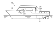
- FIG. 8 shows an engine control device 110 according to the fifth embodiment.
- a plurality of (for example, two) control units 20A and 20B are arranged at different positions.
- the first control unit 20A is arranged in the maneuvering room of the ship 115.
- the second control unit 20B is located near the deck. Shift control and throttle control of the engine 116 can be performed by the operating lever 21a of the first control unit 20A.
- the operating lever 21b of the second control unit 20B can also perform shift control and throttle control of the engine 116.
- a first select switch 117 is provided in the first control unit 20A.
- the first select switch 117 is operated when selecting and using the first control unit 20A.
- the first select switch 117 may be arranged near the first control unit 20A.
- a second select switch 118 is provided in the second control unit 20B.
- the second select switch 118 is operated when selecting and using the second control unit 20B.
- the second select switch 118 may be arranged near the second control unit 20B.
- These select switches 117 and 118 may also serve as the lock release switch 40.
- a lock release switch 40 may be provided separately from the select switches 117 and 118.
- FIG. 9 shows an engine control device 120 according to a sixth embodiment.
- the control unit 20C of this engine control device 120 includes a joystick 121.
- Joystick 121 functions as a control lever.
- the joystick 121 is moved in the longitudinal direction (indicated by arrows X1 and X2 in FIG. 9).
- the joystick 121 is moved in the left-right direction (indicated by arrows Y1 and Y2). By moving the joystick 121 diagonally, throttle control and steering can be performed simultaneously.
- the control unit 20C including the joystick 121 may be provided with the unlock switch 40 and the display 41 described in the first embodiment.
- the engine control device according to the present invention in an electric ship.
- An electric ship rotates a propeller using an engine powered by an electric motor.
- An electric motor does not require a shift mechanism because its direction of rotation changes depending on the direction in which current flows. For this reason, the operating lever for the electric boat only needs to be moved to a forward throttle range and a reverse throttle range.
- the engine control device for an electric boat may be similar to the engine control device described in the first embodiment.
Landscapes
- Engineering & Computer Science (AREA)
- Physics & Mathematics (AREA)
- General Physics & Mathematics (AREA)
- Automation & Control Theory (AREA)
- Chemical & Material Sciences (AREA)
- Combustion & Propulsion (AREA)
- Mechanical Engineering (AREA)
- Ocean & Marine Engineering (AREA)
- Radar, Positioning & Navigation (AREA)
- Remote Sensing (AREA)
- Control Of Vehicle Engines Or Engines For Specific Uses (AREA)
- Mechanical Control Devices (AREA)
Abstract
機関制御装置(11)は、操作レバー(21)を有するコントロールユニット(20)と、制御部(22)と、ロック解除スイッチ(40)とを有している。操船者が操作レバー(21)をニュートラルの位置(N)から前進側のシフト位置(F)または後進側のシフト位置(R)に移動させる前に、ロック解除スイッチ(40)を操作する。ロック解除スイッチ(40)を操作してから操作レバー(21)を移動させると、検出器(26)の出力に応じてシフト機構(15)が前進側シフトまたは後進側シフトに切り替わる。ロック解除スイッチ(40)を操作しなければ、シフトを許可する信号が出ないため操作レバー(21)は動くがシフト機構(15)は作動しない。
Description
この発明は、例えば船舶の機関のシフト操作やスロットル操作等の制御を行なうための機関制御装置に関する。
船舶の機関のシフト操作とスロットル操作とを操作レバーによって行なう機関制御装置が知られている。例えば特許文献1あるいは特許文献2に、操作レバーを備えた機関制御装置が記載されている。前記操作レバーは操船者によって操作される。特許文献2に記載されたような電気式の機関制御装置は、操作レバーの位置を検出するためのセンサを有している。このセンサの出力に応じて、シフト機構やスロットル機構が動作する。
前記操作レバーをニュートラルの位置から前進側のシフト位置に移動させる。そうすると、前記センサの出力に応じて、機関のシフト機構がニュートラルから前進側シフトに切り替わる。操作レバーをさらに前進側に移動させると、前記センサの出力に応じて、スロットル機構が動作する。スロットル機構が動作することにより、機関のスロットル制御がなされる。前記操作レバーをニュートラルの位置から後進側のシフト位置に移動させる。そうすると、前記センサの出力に応じて、機関のシフト機構がニュートラルから後進側シフトに切り替わる。操作レバーをさらに後進側に移動させると、スロットル機構が動作する。スロットル機構が動作することにより、機関のスロットル制御がなされる。
電気式の機関制御装置は、機械式の機関制御装置と比較して、操作レバーを動かす力が小さくて済むという利点がある。このため操作が楽である反面、操作レバーが操船者の意図に反して、ニュートラルの位置からシフト位置に切り替わってしまうことが懸念される。このため操作レバーをニュートラルの位置に保持するために、ロック部材を設けるのが通例である。操船者が操作レバーをニュートラルの位置からシフト位置に移動させる際、ロック解除部材によってロック部材を解除位置に移動させる。
前記操作レバーに前記ロック解除部材が設けられている場合、操作レバーをニュートラルの位置からシフト位置に移動させる際に、操船者が手でロック解除部材を操作する必要がある。このため状況に応じて操作レバーを速やかに移動させたいときに、操作しにくいことがある。操船部によっては、複数の機関制御装置が互いに隣り合って配置されていることがある。その場合、各々の操作レバーにロック部材とロック解除部材とが設けられていると、状況によっては操作に手間取ることになる。
操作性を優先させると、操作レバーにロック部材とロック解除部材とを設けないことが望まれる。しかしそのような機関制御装置は、操作レバーがニュートラルの位置にあるときに、意図せずに操作レバーが動いてしまうことがある。例えば操船者の身体の一部が操作レバーに触れたときに、操作レバーが前進側あるいは後進側のシフト位置やスロットル域に移動してしまう。
この発明の目的は、操作レバーを有する機関制御装置において、意図せずに機関のシフト機構などが作動することを回避できる機関制御装置を提供することにある。
1つの実施形態は、船舶の機関を制御する機関制御装置であって、操作レバーを有するコントロールユニットと、制御部と、ロック解除スイッチとを具備している。前記操作レバーは、少なくとも第1の位置と、第2の位置とにわたり移動可能である。第1の位置は、例えばニュートラルの位置である。第2の位置は、例えばシフト位置である。前記コントロールユニットは、前記操作レバーが前記第1の位置から前記第2の位置に移動した状態において、前記機関を制御するための信号を出力する。例えばシフト制御のための信号が出力される。前記制御部は、前記信号に基づいて前記機関を第1の状態から第2の状態に切り替える。第1の状態は、例えばニュートラルの状態である。第2の状態は、例えば前進側シフトまたは後進側シフトである。
前記制御部の1つの実施形態では、前記ロック解除スイッチが操作され、前記操作レバーが前記第1の位置から前記第2の位置に移動したときに、前記機関が前記第1の状態から前記第2の状態に切り替わる。前記ロック解除スイッチが操作されなければ、前記操作レバーが前記第1の位置から前記第2の位置に移動しても、前記機関は前記第1の状態から前記第2の状態に切り替わらない。
他の実施形態に係る制御部は、前記ロック解除スイッチが操作された状態が継続している間に、前記操作レバーが前記第1の位置から前記第2の位置に移動すると、前記機関を前記第1の状態から前記第2の状態に切り替える。前記ロック解除スイッチの操作が終わると、前記操作レバーが前記第1の位置から前記第2の位置に移動しても、前記機関は前記第1の状態から前記第2の状態に切り替わらない。
さらに別の実施形態に係る制御部は、前記ロック解除スイッチが操作されてから所定時間以内に、前記操作レバーが前記第1の位置から前記第2の位置に移動すると、前記機関を第1の状態から第2の状態に切り替える。前記ロック解除スイッチが操作されてから所定時間を超えると、前記操作レバーが前記第1の位置から前記第2の位置に移動しても、前記機関は第1の状態から第2の状態に切り替わらない。
1つの実施形態の機関制御装置では、前記第1の位置が前記操作レバーのニュートラルの位置であり、前記第2の位置が前記操作レバーのシフト位置である。前記制御部は、前記操作レバーが前記ニュートラルの位置から前記シフト位置に移動した状態において、前記機関のシフト機構をニュートラルから前進側シフトまたは後進側シフトに切り替える。
前記操作レバーは、前記ニュートラルの位置を境に、前進側のシフト位置と後進側のシフト位置とに移動可能でもよい。前記制御部は、前記ロック解除スイッチが操作されないか、または前記ロック解除スイッチが操作されてから前記所定時間を超えると、前記操作レバーのシフト位置が切り替わったときに前記機関をアイドリング状態にしてもよい。
1つの実施形態の機関制御装置が表示器を有してもよい。この表示器は、前記ロック解除スイッチが操作されたとき、前記所定時間に応じて作動する。前記所定時間を変更できるようにしてもよい。また船舶の接岸時または離岸時に前記所定時間を変更できるようにしてもよい。
1つの実施形態の機関制御装置は、互いに隣り合って配置された複数の前記コントロールユニットを有してもよい。これらコントロールユニットを有した操船部に、前記ロック解除スイッチが配置されてもよい。他の実施形態では、船舶の互いに異なる位置に配置された複数の前記コントロールユニットと、セレクトスイッチとを有してもよい。このセレクトスイッチは、複数のコントロールユニットのいずれか1つを選択して使用する際に操作される。このセレクトスイッチが前記ロック解除スイッチを兼ねてもよい。
前記操作レバーがジョイスティックでもよい。例えば機関のシフト制御およびスロットル制御を行なう際に、前記ジョイスティックを前後方向に移動させる。操舵を行なう際には前記ジョイスティックを左右方向に移動させる。
本発明の機関制御装置によれば、操作レバーが操船者の意図しない位置に移動しても機関のシフトが切り替わったりスロットル域になったりすることを回避できる。本発明の機関制御装置は、操作部材を機械的に固定するロック部材とロック解除部材とを備えた従来の機関制御装置と比較して、操作性が良い。
[第1の実施形態]
以下に第1の実施形態に係る機関制御装置について、図1から図3を参照して説明する。
図1は、船舶10の一部と、機関制御装置11とを模式的に表わした側面図である。図1は機関制御装置11を拡大して示している。船舶10の後部に、機関の一例である船外機12が搭載されている。船外機12は、エンジン13と、プロペラ14と、シフト機構15と、シフト用アクチュエータ16と、スロットル機構17と、スロットル用アクチュエータ18などを含んでいる。プロペラ14は、エンジン13を動力として回転する。シフト機構15は、プロペラ14の回転方向を切り替える機能を有している。
以下に第1の実施形態に係る機関制御装置について、図1から図3を参照して説明する。
図1は、船舶10の一部と、機関制御装置11とを模式的に表わした側面図である。図1は機関制御装置11を拡大して示している。船舶10の後部に、機関の一例である船外機12が搭載されている。船外機12は、エンジン13と、プロペラ14と、シフト機構15と、シフト用アクチュエータ16と、スロットル機構17と、スロットル用アクチュエータ18などを含んでいる。プロペラ14は、エンジン13を動力として回転する。シフト機構15は、プロペラ14の回転方向を切り替える機能を有している。
機関制御装置11は、操作レバー21を有するコントロールユニット20と、制御部22とを含んでいる。制御部22は、マイクロコンピュータ等の電気的構成を有している。コントロールユニット20は船体等の取付面に配置されている。操作レバー21は前後方向に回動可能である。操作レバー21は、シフト機構15とスロットル機構17とを操作する際に使用される。
コントロールユニット20の内部に、軸部25と、検出器26と、ディテント機構27などが設けられている。軸部25は、操作レバー21に連動して回転する。検出器26は、軸部25の回転方向の位置を検出する。ディテント機構27は、軸部25の回転に抵抗を与える。検出器26の一例は、ロータリーエンコーダ等を用いた角度センサである。角度センサは、操作レバー21の傾き、すなわち軸部25の回転方向の位置を検出する。
図1に示されたように、操作レバー21は、ニュートラルの位置Nを境に、前進側のシフト位置Fと、前進側のスロットル域S1と、後進側のシフト位置Rと、後進側のスロットル域S2とに回動させることができる。ニュートラルの位置Nは、操作レバー21の第1の位置の一例である。前進側のシフト位置Fと後進側のシフト位置Rとは、それぞれ、操作レバー21の第2の位置の一例である。
操作レバー21がニュートラルの位置Nにあるとき、検出器26の出力に基づいて、シフト機構15がニュートラル状態となる。シフト機構15のニュートラル状態は、機関の第1の状態の一例である。操作レバー21がニュートラルの位置Nから前進側のシフト位置Fに移動すると、検出器26が前進側のシフト信号を出力する。このシフト信号に基づいて、シフト機構15が前進側シフトに切り替わる。操作レバー21がニュートラルの位置Nから後進側のシフト位置Rに移動すると、検出器26が後進側のシフト信号を出力する。このシフト信号に基づいて、シフト機構15が後進側シフトに切り替わる。シフト機構15の前進側シフトと後進側シフトは、それぞれ、機関の第2の状態の一例である。
ディテント機構27は保持部材27aを有している。保持部材27aは、操作レバー21がニュートラルの位置N、または前進側のシフト位置F、または後進側のシフト位置Rにあるときに、操作レバー21の動きに抵抗を与える。操作レバー21がこれらの位置N、F、Rにあるときに抵抗が生じるため、振動等の小さな力で操作レバー21が動くことを抑制することができる。操作レバー21にある程度の力が加われば、力が加わった方向に操作レバー21が移動する。
検出器26は配線部材28を介して制御部22に接続されている。検出器26は、軸部25の回転位置に応じた信号を制御部22に出力する。軸部25の回転位置は、操作レバー21の角度に対応している。制御部22は情報処理回路を含んでいる。情報処理回路は、検出器26から出力されたシフト制御用の信号に基づいて、シフト用アクチュエータ16を制御する。また前記情報処理回路は、検出器26から出力されたスロットル制御用の信号に基づいて、スロットル用アクチュエータ18を制御する。シフト用アクチュエータ16は、ケーブル等の力伝達部材30を介してシフト機構15を駆動する。スロットル用アクチュエータ18は、ケーブル等の力伝達部材31を介してスロットル機構17を駆動する。
本実施形態の機関制御装置11はロック解除スイッチ40を備えている。ロック解除スイッチ40を設ける位置は問わない。しかし操作性を考慮すると、ロック解除スイッチ40は、例えばコントロールユニット20の外面に設けられているとよい。ロック解除スイッチ40が操作レバー21や計器板などに配置されてもよい。
ロック解除スイッチ40の近傍に表示器41が設けられている。表示器41の一例は、点灯あるいは点滅するランプである。表示器41としてのランプは、ロック解除スイッチ40がオン操作されてから所定時間T1にわたり、点灯あるいは点滅する。表示器41の他の例がブザーでもよい。表示器41としてのブザーは、ロック解除スイッチ40のオン・オフ操作に応じて鳴動する。ロック解除スイッチ40と表示器41とは、それぞれ配線部材42,43を介して制御部22に接続されている。
以下に第1の実施形態に係る機関制御装置11の作用の一例について、図2と図3に示すフローチャートを参照して説明する。
[ニュートラルからのシフト・スロットル制御]
[ニュートラルからのシフト・スロットル制御]
図2中のステップM1において、エンジン13が始動する。ステップM2では、シフト機構15がニュートラル、スロットル機構17がアイドリング状態にある。操船者がシフト機構15を前進側シフトあるいは後進側シフトに切り替える際に、操船者がロック解除スイッチ40をオン操作する。
ステップM3では、ロック解除スイッチ40がオン操作されたか否かが判断される。ステップM3において“YES”は、ロック解除スイッチ40がオンされた場合である。ステップM3において“YES”であれば、ステップM4に進む。ステップM4では、シフト信号の受付けを許可するモード(ロック解除)となり、図3のステップM6に進む。
ステップM3において“NO”は、ロック解除スイッチ40がオン操作されていない場合である。ステップM3において“NO”であれば、ステップM5に進む。ステップM5では、シフト信号の受付けを拒否するモード(ロック状態)となる。このロック状態のもとで、操作レバー21は前後方向に動くことができる。
図3中のステップM6では、操作レバー21がニュートラルの位置Nからシフト位置に移動したか否かが判断される。ここで言うシフト位置は、前進側のシフト位置Fまたは後進側のシフト位置Rである。ステップM6において“YES”は、操作レバー21がシフト位置に移動した場合である。ステップM6において“YES”であれば、ステップM7に進む。ステップM7において、シフト機構15がニュートラルから前進側シフトまたは後進側シフトに切り替わる。ステップM6において“NO”は、操作レバー21がシフト位置に移動していない場合である。ステップM6において“NO”であれば、ステップM8に進み、シフト機構15がニュートラルに維持される。
このように操船者は、シフト機構15をニュートラルから前進側シフトまたは後進側シフトに切り替える際、まずロック解除スイッチ40をオン操作する。そののち、操作レバー21を前進側のシフト位置Fまたは後進側のシフト位置Rに移動させる。ロック解除スイッチ40をオン操作しない場合、操作レバー21は動くが、シフト信号が出ない。このためシフト機構15は作動しない。よって、操船者の意図に反して操作レバー21がニュートラルの位置Nから前進側のシフト位置Fまたは後進側のシフト位置Rに切り替わったとしても、シフト機構15が作動してしまうことを回避できる。
操作レバー21がニュートラルの位置Nから前進側のシフト位置Fに移動すると、軸部25が第1の方向に回転する。軸部25が第1の方向に回転すると、前進側のシフトのための信号が、検出器26から制御部22に出力される。この信号に基づいて、シフト用アクチュエータ16が作動する。シフト用アクチュエータ16が作動することにより、シフト機構15がニュートラルから前進側シフトに切り替わる。
操作レバー21がニュートラルの位置Nから後進側のシフト位置Rに移動すると、軸部25が第2の方向に回転する。軸部25が第2の方向に回転すると、後進側のシフトのための信号が、検出器26から制御部22に出力される。この信号に基づいて、シフト用アクチュエータ16が作動する。シフト用アクチュエータ16が作動することにより、シフト機構15がニュートラルから後進側シフトに切り替わる。
エンジン13を増速させるために、スロットル機構17を操作する。その場合、操作レバー21をスロットル域(図1中のS1またはS2)まで移動させる。
図3中のステップM9において、操作レバー21がスロットル域(S1またはS2)に移動したか否かが判断される。ステップM9において“YES”は、操作レバー21がスロットル域に移動した場合である。ステップM9において“YES”であれば、ステップM10に進む。
図3中のステップM9において、操作レバー21がスロットル域(S1またはS2)に移動したか否かが判断される。ステップM9において“YES”は、操作レバー21がスロットル域に移動した場合である。ステップM9において“YES”であれば、ステップM10に進む。
ステップM10では、操作レバー21の角度に応じてスロットル機構17が操作される。スロットル機構17が操作されることにより、エンジン13の増速あるいは減速がなされる。たとえば操作レバー21を前進側のスロットル操作域S1(図1に示す)に移動させると、操作レバー21の角度に応じて軸部25が第1の方向にさらに回転する。このため操作レバー21の角度に応じて、スロットル制御のための信号が検出器26から制御部22に出力される。この信号に基づき、スロットル用アクチュエータ18が制御され、スロットル開度が変化する。スロットル開度に応じた回転速度でプロペラ14が回転する。
操船者が操作レバー21を後進側のスロットル操作域S2(図1に示す)に移動させる。そうすると、操作レバー21の角度に応じて、スロットル制御のための信号が検出器26から制御部22に出力される。この信号に基づき、スロットル用アクチュエータ18が制御され、スロットル開度が変化する。スロットル開度に応じた回転速度でプロペラ14が回転する。
図3中のステップM9において“NO”は、操作レバー21がスロットル域に移動していないと判断された場合である。ステップM9において“NO”であれば、スロットル機構17は操作されない。このためエンジン13はステップM11のアイドリング状態となる。
[第2の実施形態]
第2の実施形態のフローチャートは、第1の実施形態のフローチャート(図2および図3)と実質的に共通である。ただし第2の実施形態の場合、図2中のステップM3において、ロック解除スイッチ40がオン操作された状態が「継続しているか否か」が判断される。
第2の実施形態のフローチャートは、第1の実施形態のフローチャート(図2および図3)と実質的に共通である。ただし第2の実施形態の場合、図2中のステップM3において、ロック解除スイッチ40がオン操作された状態が「継続しているか否か」が判断される。
ステップM3において“YES”は、ロック解除スイッチ40がオン操作され、その状態が継続している場合である。ステップM3において“YES”であれば。操作レバー21を第1の位置から第2の位置に移動させたとき、機関が第1の状態から第2の状態に切り替わる。第1の位置と第1の状態とは、例えばニュートラルである。第2の位置と第2の状態とは、例えば前進側のシフトである。第2の位置と第2の状態とが、それぞれ後進側のシフトであってもよい。
ロック解除スイッチ40のオン操作が終わると、操作レバー21が第1の位置から第2の位置に移動しても、機関が第1の状態から第2の状態に切り替わることが禁止される。すなわちシフト信号の受付けが拒否される。
ロック解除スイッチ40のオン操作が終わると、操作レバー21が第1の位置から第2の位置に移動しても、機関が第1の状態から第2の状態に切り替わることが禁止される。すなわちシフト信号の受付けが拒否される。
[第3の実施形態]
以下に第3の実施形態に係る機関制御装置11の作用の一例について、図4から図6に示すフローチャートを参照して説明する。
[ニュートラルからのシフト・スロットル制御]
図4はニュートラルからのシフト・スロットル制御の処理の前半の部分を示している。図5はシフト・スロットル制御の処理の後半の部分を示している。
以下に第3の実施形態に係る機関制御装置11の作用の一例について、図4から図6に示すフローチャートを参照して説明する。
[ニュートラルからのシフト・スロットル制御]
図4はニュートラルからのシフト・スロットル制御の処理の前半の部分を示している。図5はシフト・スロットル制御の処理の後半の部分を示している。
図4中のステップST1では、操作レバー21がニュートラルの位置N(図1に示す)にある。電気系の電源がオンになると、ステップST2において初期値(例えば所定時間T1)が設定される。所定時間T1は、予め設定されたデフォルトの固定値でもよいし、必要に応じてマニュアル操作により入力された値でもよい。ステップST3ではエンジン13が始動し、アイドリング状態(ステップST4)となる。
シフト機構15を前進側シフトあるいは後進側シフトに切り替える際に、操船者がロック解除スイッチ40をオン操作する。
ステップST5において、ロック解除スイッチ40がオン操作されたか否かが判断される。ステップST5において“YES”は、ロック解除スイッチ40がオンされた場合である。ステップST5において“YES”であれば、ステップST6に進む。ステップST5において“NO”は、ロック解除スイッチ40がオン操作されていない場合である。ステップST5において“NO”であれば、ステップST4に戻る。
ステップST5において、ロック解除スイッチ40がオン操作されたか否かが判断される。ステップST5において“YES”は、ロック解除スイッチ40がオンされた場合である。ステップST5において“YES”であれば、ステップST6に進む。ステップST5において“NO”は、ロック解除スイッチ40がオン操作されていない場合である。ステップST5において“NO”であれば、ステップST4に戻る。
ステップST6では、操作レバー21がニュートラルの位置Nからシフト位置に移動したか否かが判断される。シフト位置は、前進側のシフト位置Fまたは後進側のシフト位置Rである。ステップST6において“YES”は、操作レバー21がシフト位置に移動した場合である。ステップST6において“YES”であれば、ステップST7に進む。ステップST6において“NO”は、操作レバー21がシフト位置に移動していない場合である。ステップST6において“NO”であれば、ステップST8に進む。ステップST8では、シフト機構15がニュートラルに維持されるとともに、スロットル機構17がアイドリング状態となる。
ステップST7において、所定時間T1(例えば3秒)を超えているか否かが判断される。ステップST7において“NO”は、ロック解除スイッチ40がオン操作されてから所定時間T1を超えている場合である。ステップST7において“NO”であれば、ステップST9に進む。ステップST9では、シフト用の信号の受付けを拒否するモード(ロック状態)となる。このためシフト機構15がニュ-トラルから前進側シフトまたは後進側シフトに切り替わることが禁止される。
ステップST7において“YES”は、所定時間T1以内であると判断された場合である。ステップST7において“YES”であれば、図5中のステップST10に進む。ステップST10では、シフト用の信号の受付けを許可するモード(ロック解除)となる。このためステップST11において、シフト機構15がニュートラルから前進側シフトまたは後進側シフトに切り替わる。
このように操船者は、シフト機構15をニュートラルから前進側シフトまたは後進側シフトに切り替える際、ロック解除スイッチ40をオン操作する。オン操作してから所定時間T1以内に、操作レバー21を前進側のシフト位置Fまたは後進側のシフト位置Rに移動させる。すなわちロック解除スイッチ40を所定時間T1以内に操作しなければ、シフト機構15は作動しない。
このため操船者の意図に反して、操作レバー21がニュートラルの位置Nから前進側のシフト位置Fまたは後進側のシフト位置Rに切り替わったとしても、シフト機構15が作動してしまうことを回避できる。ロック解除スイッチ40がオン操作されてから所定時間T1を経過するまでは、表示器41を点灯あるいは鳴動させてもよい。こうすることにより、所定時間T1以内であることを操船者に報知することができる。
エンジン13を増速させるにはスロットル機構17を操作する。スロットル機構17を操作する場合、操作レバー21をスロットル域(図1中のS1またはS2)まで移動させる。
図5中のステップST12において、操作レバー21がスロットル域(S1またはS2)に移動したか否かが判断される。ステップST12において“YES”は、操作レバー21がスロットル域に移動した場合である。ステップST12において“YES”であれば、ステップST13に進む。
図5中のステップST12において、操作レバー21がスロットル域(S1またはS2)に移動したか否かが判断される。ステップST12において“YES”は、操作レバー21がスロットル域に移動した場合である。ステップST12において“YES”であれば、ステップST13に進む。
ステップST13では、操作レバー21の角度に応じてスロットル機構17が操作され、エンジン13の増速あるいは減速がなされる。
ステップST12において“NO”は、操作レバー21がスロットル域に移動していないと判断された場合である。ステップST12において“NO”であれば、スロットル機構17は操作されない。このためステップST14においてエンジン13がアイドリング状態となる。
ステップST12において“NO”は、操作レバー21がスロットル域に移動していないと判断された場合である。ステップST12において“NO”であれば、スロットル機構17は操作されない。このためステップST14においてエンジン13がアイドリング状態となる。
ステップST15において“YES”は、操作レバー21がニュートラルの位置Nに戻されたと判断された場合である。ステップST15において“YES”であれば、上記の一連のシフト・スロットル処理が終了となり、初期の状態(図4中のステップST4)に戻る。ステップST15において“NO”は、操作レバー21がニュートラルの位置Nに戻されていない場合である。ステップST15において“NO”であれば、ステップST13に戻り、スロットル制御が継続される。
[シフト急変対策]
操船者の意図と無関係に、操作レバー21のシフト位置(前進側と後進側)が急に切り替わる可能性も否定できない。例えば操作レバー21が前進側のシフト位置Fにあり、しかもスロットル機構17が増速状態にあるとする。そのとき乗船者の身体が操作レバー21に当たるなどして、操作レバー21が後進側のシフト位置Rに切り替わることが考えられる。このため本実施形態の機関制御装置11は、図6に示すようにシフトの急変に対する安全策を講じてもよい。
操船者の意図と無関係に、操作レバー21のシフト位置(前進側と後進側)が急に切り替わる可能性も否定できない。例えば操作レバー21が前進側のシフト位置Fにあり、しかもスロットル機構17が増速状態にあるとする。そのとき乗船者の身体が操作レバー21に当たるなどして、操作レバー21が後進側のシフト位置Rに切り替わることが考えられる。このため本実施形態の機関制御装置11は、図6に示すようにシフトの急変に対する安全策を講じてもよい。
操船者がシフトを切り替える場合、切り替える前にロック解除スイッチ40をオン操作する。そして所定時間T1(例えば3秒)以内に、操作レバー21のシフト位置を切り替える。
図6中のステップST20では、シフト機構15が前進側シフトまたは後進側シフトとなっている。このときスロットル機構17は、エンジン13の回転をアイドリング時よりも増速させている。図6中のステップST21において、ロック解除スイッチ40がオン操作されたか否かが判断される。ステップST21において“YES”は、ロック解除スイッチ40がオン操作された場合である。ステップST21において“YES”であれば、ステップST22に進む。
ステップST22では、操作レバー21のシフト位置が切り替わったか否かが判断される。ステップST22において“YES”は、操作レバー21のシフト位置が切り替わった場合である。ステップST22において“YES”であれば、ステップST23に進む。ステップST22において“NO”は、操作レバー21のシフト位置が切り替わっていない場合である。ステップST22において“NO”であれば、ステップST24に移る。ステップST24では、シフト機構15のシフトが切り替わらずに維持される。
ステップST23において、所定時間T1以内か否かが判断される。ステップST23において“YES”は、ロック解除スイッチ40がオン操作されてから所定時間T1以内の場合である。ステップST23において“YES”であれば、ステップST25に進む。ステップST25では、シフト制御のための信号の受付けを許可するモード(ロック解除)となる。このため操作レバー21の位置に応じて、シフト機構15が前進側シフトまたは後進側シフトに切り替わる。
操作レバー21がスロットル域S1またはS2に移動していれば、操作レバー21の角度に応じたスロットル制御のための信号が、検出器26から出力される。この信号に基づいてスロットル機構17が作動し、エンジン13の増速あるいは減速がなされる。
ステップST23において“NO”は、所定時間T1を超えていない場合である。ステップST23において“NO”であれば、ステップST26に進む。ステップST26では、シフト機構15とスロットル機構17の作動を禁止するモード(ロック状態)となる。このため操作レバー21が操船者の意図しない方向に切り替わっても、シフト機構15は切り替わらないし、エンジンが増速することもない。このため機関はアイドリング状態となる。
例えば船舶の接岸時や離岸時では、操作レバー21のシフト位置(前進側または後進側)を頻繁に切り替える可能性がある。その場合、所定時間T1を延長するなど、所定時間T1を変更してもよい。船舶の接岸時、離岸時を判断する手段としては、手動のスイッチによって制御部22に接岸時または離岸時であることを入力してもよい。あるいは船舶に配置した距離センサ等による情報に基づいて、桟橋と船舶との相対位置の変化を判断してもよい。
[第4の実施形態]
図7は第4の実施形態に係る機関制御装置100を示している。この機関制御装置100の操船部101は、互いに隣り合って配置された複数(例えば2台)のコントロールユニット20A,20Bを含んでいる。一方のコントロールユニット20Aの操作レバー21aは、第1の機関を制御するために使用される。他方のコントロールユニット20Bの操作レバー21bは、第2の機関を制御するために使用される。操作レバー21a,21bの構成と作用は、第1の実施形態で説明した操作レバー21と共通でよい。
図7は第4の実施形態に係る機関制御装置100を示している。この機関制御装置100の操船部101は、互いに隣り合って配置された複数(例えば2台)のコントロールユニット20A,20Bを含んでいる。一方のコントロールユニット20Aの操作レバー21aは、第1の機関を制御するために使用される。他方のコントロールユニット20Bの操作レバー21bは、第2の機関を制御するために使用される。操作レバー21a,21bの構成と作用は、第1の実施形態で説明した操作レバー21と共通でよい。
コントロールユニット20A,20Bを有する操船部101に、ロック解除スイッチ40と表示器41とが配置されている。ロック解除スイッチ40および表示器41の構成と作用は、第1の実施形態で説明したロック解除スイッチ40および表示器41と共通であるため説明を省略する。
図7に示された機関制御装置100は、複数のコントロールユニット20A,20Bのうち少なくとも1つを使用してシフト制御およびスロットル制御を行なう。そのシフト制御およびスロットル制御を際に、ロック解除スイッチ40をオン操作する。ロック解除スイッチ40をオン操作すると、シフトの切り替えを許可するロック解除モードとする。ロック解除スイッチ40をオン操作しなければ、シフトの切り替えを禁止するロックモードとなる。各々のコントロールユニット20A,20Bに、それぞれロック解除スイッチ40と表示器41とが配置されていてもよい。
[第5の実施形態]
図8は、第5の実施形態に係る機関制御装置110を示している。この機関制御装置110では、複数(例えば2台)のコントロールユニット20A,20Bが、互いに異なる位置に配置されている。例えば第1のコントロールユニット20Aが船舶115の操船室に配置されている。第2のコントロールユニット20Bはデッキ付近に配置されている。第1のコントロールユニット20Aの操作レバー21aによって、機関116のシフト制御とスロットル制御を行なうことができる。第2のコントロールユニット20Bの操作レバー21bも、機関116のシフト制御とスロットル制御を行なうことができる。
図8は、第5の実施形態に係る機関制御装置110を示している。この機関制御装置110では、複数(例えば2台)のコントロールユニット20A,20Bが、互いに異なる位置に配置されている。例えば第1のコントロールユニット20Aが船舶115の操船室に配置されている。第2のコントロールユニット20Bはデッキ付近に配置されている。第1のコントロールユニット20Aの操作レバー21aによって、機関116のシフト制御とスロットル制御を行なうことができる。第2のコントロールユニット20Bの操作レバー21bも、機関116のシフト制御とスロットル制御を行なうことができる。
図8に示されたように、第1のコントロールユニット20Aに、第1のセレクトスイッチ117が設けられている。第1のセレクトスイッチ117は、第1のコントロールユニット20Aを選択して使用する際に操作される。第1のセレクトスイッチ117が、第1のコントロールユニット20Aの近傍に配置されていてもよい。
第2のコントロールユニット20Bに、第2のセレクトスイッチ118が設けられている。第2のセレクトスイッチ118は、第2のコントロールユニット20Bを選択して使用する際に操作される。第2のセレクトスイッチ118が、第2のコントロールユニット20Bの近傍に配置されていてもよい。これらセレクトスイッチ117,118が、ロック解除スイッチ40を兼ねていてもよい。セレクトスイッチ117,118とは別に、ロック解除スイッチ40が設けられていてもよい。
第2のコントロールユニット20Bに、第2のセレクトスイッチ118が設けられている。第2のセレクトスイッチ118は、第2のコントロールユニット20Bを選択して使用する際に操作される。第2のセレクトスイッチ118が、第2のコントロールユニット20Bの近傍に配置されていてもよい。これらセレクトスイッチ117,118が、ロック解除スイッチ40を兼ねていてもよい。セレクトスイッチ117,118とは別に、ロック解除スイッチ40が設けられていてもよい。
[第6の実施形態]
図9は第6の実施形態に係る機関制御装置120を示している。この機関制御装置120のコントロールユニット20Cは、ジョイスティック121を備えている。ジョイスティック121は、操作レバーとして機能する。機関のシフト制御およびスロットル制御を行なう際、ジョイスティック121を前後方向(図9中に矢印X1,X2で示す)に移動させる。船舶の操舵を行なう際に、ジョイスティック121を左右方向(矢印Y1,Y2で示す)に移動させる。ジョイスティック121を斜め方向に移動させると、スロットル制御と操舵を同時に行うことができる。
図9は第6の実施形態に係る機関制御装置120を示している。この機関制御装置120のコントロールユニット20Cは、ジョイスティック121を備えている。ジョイスティック121は、操作レバーとして機能する。機関のシフト制御およびスロットル制御を行なう際、ジョイスティック121を前後方向(図9中に矢印X1,X2で示す)に移動させる。船舶の操舵を行なう際に、ジョイスティック121を左右方向(矢印Y1,Y2で示す)に移動させる。ジョイスティック121を斜め方向に移動させると、スロットル制御と操舵を同時に行うことができる。
ジョイスティック121を前後方向に移動させると、図1に示された操作レバー21と同様に、ジョイスティック121の角度に応じてシフト操作およびスロットル操作を行なうことができる。ジョイスティック121を左右方向に移動させると、ジョイスティック121の角度に応じて舵が動く。ジョイスティック121を備えたコントロールユニット20Cに、第1の実施形態で説明したロック解除スイッチ40と表示器41とが設けられていてもよい。
本発明に係る機関制御装置を電動船舶に使用することも可能である。電動船舶は電動モータを動力源とする機関によってプロペラを回転させる。電動モータは電流が流れる方向に応じて回転方向が変わるため、シフト機構が不要である。このため電動船舶用の操作レバーは、前進側のスロットル域と後進側のスロットル域とに移動すればよい。それ以外の構成と作用について、電動船舶用の機関制御装置は、第1の実施形態で説明した機関制御装置と同様でもよい。
本発明を実施するに当たり、機関制御装置が使用される船舶や機関など、本発明を構成する各要素の構成や配置などの具体的な態様を必要に応じて変更して実施できることは言うまでもない。
10…船舶、11…機関制御装置、12…船外機(機関の一例)、13…エンジン、15…シフト機構、16…シフト用アクチュエータ、17…スロットル機構、18…スロットル用アクチュエータ、20,20A,20B,20C…コントロールユニット、21,21a,21b…操作レバー、22…制御部、26…検出器、27…ディテント機構、40…ロック解除スイッチ、41…表示器、100…機関制御装置、101…操船部、110…機関制御装置、117,118…セレクトスイッチ、120…機関制御装置、121…ジョイスティック。
Claims (11)
- 船舶の機関を制御する機関制御装置であって、
少なくとも第1の位置と第2の位置とにわたり移動可能な操作レバー(21)を有し、前記操作レバー(21)が前記第1の位置から前記第2の位置に移動した状態において前記機関を第1の状態から第2の状態に切り替えるための信号を出力するコントロールユニット(20)(20A)(20B)(20C)と
前記信号に基づいて前記機関を制御する制御部(22)と、
ロック解除スイッチ(40)とを有し、
前記制御部(22)は、
前記ロック解除スイッチ(40)が操作され、前記操作レバー(21)が前記第1の位置から前記第2の位置に移動したときに、前記機関を前記第1の状態から前記第2の状態に切り替え、
前記ロック解除スイッチ(40)が操作されなければ、前記操作レバー(21)が前記第1の位置から前記第2の位置に移動しても、前記機関を前記第1の状態から前記第2の状態に切り替えないことを特徴とする船舶の機関制御装置。 - 請求項1に記載の機関制御装置において、
前記制御部(22)は、
前記ロック解除スイッチ(40)が操作された状態が継続している間に、前記操作レバー(21)が前記第1の位置から前記第2の位置に移動すると、前記機関を前記第1の状態から前記第2の状態に切り替え、
前記ロック解除スイッチ(40)の操作が終わると、前記操作レバー(21)が前記第1の位置から前記第2の位置に移動しても、前記機関を前記第1の状態から前記第2の状態に切り替えないことを特徴とする船舶の機関制御装置。 - 請求項1に記載の機関制御装置において、
前記制御部(22)は、前記ロック解除スイッチ(40)が操作されてから所定時間以内に前記操作レバー(21)が前記第1の位置から前記第2の位置に移動した状態において、前記機関を前記第1の状態から前記第2の状態に切り替え、
前記ロック解除スイッチ(40)が操作されてから前記所定時間を超えると、前記操作レバー(21)が前記第1の位置から前記第2の位置に移動しても、前記機関を前記第1の状態から前記第2の状態に切り替えないことを特徴とする船舶の機関制御装置。 - 請求項1に記載の機関制御装置において、
前記第1の位置がニュートラルの位置であり、
前記第2の位置がシフト位置であり、
前記制御部(22)は、
前記操作レバー(21)が前記ニュートラルの位置から前記シフト位置に移動した状態において、前記機関のシフト機構(15)をニュートラルから前進側シフトまたは後進側シフトに切り替える機関制御装置。 - 請求項3に記載の機関制御装置において、
前記第1の位置がニュートラルの位置であり、
前記第2の位置がシフト位置であり、
前記操作レバー(21)がニュートラルの位置を境に前進側のシフト位置と後進側のシフト位置とに移動可能であり、
前記制御部(22)は、
前記ロック解除スイッチ(40)が操作されないかまたは前記ロック解除スイッチ(40)が操作されてから前記所定時間を超えた状態において、前記操作レバー(21)のシフト位置が切り替わったときに前記機関をアイドリング状態とする機関制御装置。 - 請求項3に記載の機関制御装置において、
前記ロック解除スイッチ(40)が操作されたときに前記所定時間に応じて作動する表示器(41)を有した機関制御装置。 - 請求項3に記載の機関制御装置において、
前記所定時間を変更可能な機関制御装置。 - 請求項7に記載の機関制御装置において、
前記船舶の接岸時または離岸時に前記所定時間を変更可能な機関制御装置。 - 請求項1に記載の機関制御装置において、
互いに隣り合って配置された複数の前記コントロールユニット(20A)(20B)からなる操船部(101)を有し、
前記操船部(101)に前記ロック解除スイッチ(40)が配置された機関制御装置。 - 請求項1に記載の機関制御装置において、
前記船舶の互いに異なる位置に配置された複数の前記コントロールユニット(20A)(20B)と、
前記複数のコントロールユニット(20A)(20B)のいずれか1つを選択して使用する際に操作するセレクトスイッチ(117)(118)とを有し、
前記セレクトスイッチ(117)(118)が前記ロック解除スイッチ(40)を兼ねた機関制御装置。 - 請求項1に記載の機関制御装置において、
前記コントロールユニット(20C)の前記操作レバー(21)がジョイスティック(121)からなり、シフト制御およびスロットル制御を行なう際に前記ジョイスティック(121)を前後方向に移動させ、操舵を行なう際に前記ジョイスティック(121)を左右方向に移動させる機関制御装置。
Applications Claiming Priority (2)
| Application Number | Priority Date | Filing Date | Title |
|---|---|---|---|
| JP2022074983A JP2023163820A (ja) | 2022-04-28 | 2022-04-28 | 船舶の機関制御装置 |
| JP2022-074983 | 2022-04-28 |
Publications (1)
| Publication Number | Publication Date |
|---|---|
| WO2023210537A1 true WO2023210537A1 (ja) | 2023-11-02 |
Family
ID=88518897
Family Applications (1)
| Application Number | Title | Priority Date | Filing Date |
|---|---|---|---|
| PCT/JP2023/015967 Ceased WO2023210537A1 (ja) | 2022-04-28 | 2023-04-21 | 船舶の機関制御装置 |
Country Status (2)
| Country | Link |
|---|---|
| JP (1) | JP2023163820A (ja) |
| WO (1) | WO2023210537A1 (ja) |
Citations (4)
| Publication number | Priority date | Publication date | Assignee | Title |
|---|---|---|---|---|
| US20030019414A1 (en) * | 1999-11-09 | 2003-01-30 | Borrett John Robert | Waterjet control system |
| JP2016206897A (ja) * | 2015-04-21 | 2016-12-08 | ヤマハ発動機株式会社 | 船舶用タッチパネル装置 |
| US20200180744A1 (en) * | 2018-12-05 | 2020-06-11 | Brunswick Corporation | Configurable remote control system and method for a marine vessel |
| JP2021006451A (ja) * | 2018-11-01 | 2021-01-21 | ブランズウィック コーポレーション | 船舶の低速推進を制御するための方法およびシステム |
-
2022
- 2022-04-28 JP JP2022074983A patent/JP2023163820A/ja active Pending
-
2023
- 2023-04-21 WO PCT/JP2023/015967 patent/WO2023210537A1/ja not_active Ceased
Patent Citations (4)
| Publication number | Priority date | Publication date | Assignee | Title |
|---|---|---|---|---|
| US20030019414A1 (en) * | 1999-11-09 | 2003-01-30 | Borrett John Robert | Waterjet control system |
| JP2016206897A (ja) * | 2015-04-21 | 2016-12-08 | ヤマハ発動機株式会社 | 船舶用タッチパネル装置 |
| JP2021006451A (ja) * | 2018-11-01 | 2021-01-21 | ブランズウィック コーポレーション | 船舶の低速推進を制御するための方法およびシステム |
| US20200180744A1 (en) * | 2018-12-05 | 2020-06-11 | Brunswick Corporation | Configurable remote control system and method for a marine vessel |
Also Published As
| Publication number | Publication date |
|---|---|
| JP2023163820A (ja) | 2023-11-10 |
Similar Documents
| Publication | Publication Date | Title |
|---|---|---|
| US8170735B2 (en) | Marine vessel maneuvering supporting apparatus and marine vessel including the same | |
| USRE39032E1 (en) | Multipurpose control mechanism for a marine vessel | |
| US8156882B2 (en) | Marine vessel steering apparatus and marine vessel including the same | |
| US7775844B2 (en) | Electronically assisted reverse gate system for a jet propulsion watercraft | |
| JP4673187B2 (ja) | 多機掛け推進機の制御装置 | |
| US8046121B2 (en) | Watercraft steering device and watercraft | |
| JP5128144B2 (ja) | 船舶推進機及び船舶 | |
| JP4901245B2 (ja) | 船舶推進装置及び船舶 | |
| JP4571295B2 (ja) | 小型船舶用リモートコントロール装置 | |
| US10472039B2 (en) | Hydraulic steering system for a watercraft | |
| US12528572B2 (en) | Watercraft propulsion system, and watercraft | |
| US20080119096A1 (en) | Boat steering system | |
| JP2007186139A (ja) | 船舶 | |
| JP2025125465A (ja) | 操船システム、操船システムの制御方法及び船舶 | |
| WO2023210537A1 (ja) | 船舶の機関制御装置 | |
| JP5249110B2 (ja) | 船舶用推進システム | |
| JP5449510B2 (ja) | 操船支援装置 | |
| JP2005335449A (ja) | 船舶 | |
| EP4375182B1 (en) | Watercraft propulsion system, and watercraft including the watercraft propulsion system | |
| US20250042526A1 (en) | Watercraft propulsion system, and watercraft | |
| GB2417300A (en) | Retractable selector mechanism for a motor vehicle transmission | |
| JP5147461B2 (ja) | 小型船舶の停止装置 | |
| GB2512865A (en) | Marine vessel dynamic positioning control system | |
| JP4249823B2 (ja) | 小型船舶用ノズル駆動装置 | |
| JPH0858692A (ja) | 船舶の推進機の遠隔操作装置 |
Legal Events
| Date | Code | Title | Description |
|---|---|---|---|
| 121 | Ep: the epo has been informed by wipo that ep was designated in this application |
Ref document number: 23796279 Country of ref document: EP Kind code of ref document: A1 |
|
| NENP | Non-entry into the national phase |
Ref country code: DE |
|
| 122 | Ep: pct application non-entry in european phase |
Ref document number: 23796279 Country of ref document: EP Kind code of ref document: A1 |