WO2023210536A1 - 演算装置、及び、車両の制御装置 - Google Patents
演算装置、及び、車両の制御装置 Download PDFInfo
- Publication number
- WO2023210536A1 WO2023210536A1 PCT/JP2023/015966 JP2023015966W WO2023210536A1 WO 2023210536 A1 WO2023210536 A1 WO 2023210536A1 JP 2023015966 W JP2023015966 W JP 2023015966W WO 2023210536 A1 WO2023210536 A1 WO 2023210536A1
- Authority
- WO
- WIPO (PCT)
- Prior art keywords
- solution
- vehicle
- braking
- driving force
- evaluation function
- Prior art date
- Legal status (The legal status is an assumption and is not a legal conclusion. Google has not performed a legal analysis and makes no representation as to the accuracy of the status listed.)
- Ceased
Links
Images


Classifications
-
- B—PERFORMING OPERATIONS; TRANSPORTING
- B60—VEHICLES IN GENERAL
- B60W—CONJOINT CONTROL OF VEHICLE SUB-UNITS OF DIFFERENT TYPE OR DIFFERENT FUNCTION; CONTROL SYSTEMS SPECIALLY ADAPTED FOR HYBRID VEHICLES; ROAD VEHICLE DRIVE CONTROL SYSTEMS FOR PURPOSES NOT RELATED TO THE CONTROL OF A PARTICULAR SUB-UNIT
- B60W50/00—Details of control systems for road vehicle drive control not related to the control of a particular sub-unit, e.g. process diagnostic or vehicle driver interfaces
- B60W50/06—Improving the dynamic response of the control system, e.g. improving the speed of regulation or avoiding hunting or overshoot
-
- B—PERFORMING OPERATIONS; TRANSPORTING
- B60—VEHICLES IN GENERAL
- B60W—CONJOINT CONTROL OF VEHICLE SUB-UNITS OF DIFFERENT TYPE OR DIFFERENT FUNCTION; CONTROL SYSTEMS SPECIALLY ADAPTED FOR HYBRID VEHICLES; ROAD VEHICLE DRIVE CONTROL SYSTEMS FOR PURPOSES NOT RELATED TO THE CONTROL OF A PARTICULAR SUB-UNIT
- B60W40/00—Estimation or calculation of non-directly measurable driving parameters for road vehicle drive control systems not related to the control of a particular sub unit, e.g. by using mathematical models
-
- B—PERFORMING OPERATIONS; TRANSPORTING
- B60—VEHICLES IN GENERAL
- B60W—CONJOINT CONTROL OF VEHICLE SUB-UNITS OF DIFFERENT TYPE OR DIFFERENT FUNCTION; CONTROL SYSTEMS SPECIALLY ADAPTED FOR HYBRID VEHICLES; ROAD VEHICLE DRIVE CONTROL SYSTEMS FOR PURPOSES NOT RELATED TO THE CONTROL OF A PARTICULAR SUB-UNIT
- B60W40/00—Estimation or calculation of non-directly measurable driving parameters for road vehicle drive control systems not related to the control of a particular sub unit, e.g. by using mathematical models
- B60W40/12—Estimation or calculation of non-directly measurable driving parameters for road vehicle drive control systems not related to the control of a particular sub unit, e.g. by using mathematical models related to parameters of the vehicle itself, e.g. tyre models
- B60W40/13—Load or weight
-
- G—PHYSICS
- G06—COMPUTING OR CALCULATING; COUNTING
- G06F—ELECTRIC DIGITAL DATA PROCESSING
- G06F17/00—Digital computing or data processing equipment or methods, specially adapted for specific functions
- G06F17/10—Complex mathematical operations
-
- G—PHYSICS
- G06—COMPUTING OR CALCULATING; COUNTING
- G06F—ELECTRIC DIGITAL DATA PROCESSING
- G06F17/00—Digital computing or data processing equipment or methods, specially adapted for specific functions
- G06F17/10—Complex mathematical operations
- G06F17/17—Function evaluation by approximation methods, e.g. inter- or extrapolation, smoothing, least mean square method
-
- B—PERFORMING OPERATIONS; TRANSPORTING
- B60—VEHICLES IN GENERAL
- B60W—CONJOINT CONTROL OF VEHICLE SUB-UNITS OF DIFFERENT TYPE OR DIFFERENT FUNCTION; CONTROL SYSTEMS SPECIALLY ADAPTED FOR HYBRID VEHICLES; ROAD VEHICLE DRIVE CONTROL SYSTEMS FOR PURPOSES NOT RELATED TO THE CONTROL OF A PARTICULAR SUB-UNIT
- B60W2520/00—Input parameters relating to overall vehicle dynamics
- B60W2520/10—Longitudinal speed
- B60W2520/105—Longitudinal acceleration
-
- B—PERFORMING OPERATIONS; TRANSPORTING
- B60—VEHICLES IN GENERAL
- B60W—CONJOINT CONTROL OF VEHICLE SUB-UNITS OF DIFFERENT TYPE OR DIFFERENT FUNCTION; CONTROL SYSTEMS SPECIALLY ADAPTED FOR HYBRID VEHICLES; ROAD VEHICLE DRIVE CONTROL SYSTEMS FOR PURPOSES NOT RELATED TO THE CONTROL OF A PARTICULAR SUB-UNIT
- B60W2520/00—Input parameters relating to overall vehicle dynamics
- B60W2520/12—Lateral speed
- B60W2520/125—Lateral acceleration
-
- B—PERFORMING OPERATIONS; TRANSPORTING
- B60—VEHICLES IN GENERAL
- B60W—CONJOINT CONTROL OF VEHICLE SUB-UNITS OF DIFFERENT TYPE OR DIFFERENT FUNCTION; CONTROL SYSTEMS SPECIALLY ADAPTED FOR HYBRID VEHICLES; ROAD VEHICLE DRIVE CONTROL SYSTEMS FOR PURPOSES NOT RELATED TO THE CONTROL OF A PARTICULAR SUB-UNIT
- B60W2520/00—Input parameters relating to overall vehicle dynamics
- B60W2520/14—Yaw
-
- B—PERFORMING OPERATIONS; TRANSPORTING
- B60—VEHICLES IN GENERAL
- B60W—CONJOINT CONTROL OF VEHICLE SUB-UNITS OF DIFFERENT TYPE OR DIFFERENT FUNCTION; CONTROL SYSTEMS SPECIALLY ADAPTED FOR HYBRID VEHICLES; ROAD VEHICLE DRIVE CONTROL SYSTEMS FOR PURPOSES NOT RELATED TO THE CONTROL OF A PARTICULAR SUB-UNIT
- B60W2520/00—Input parameters relating to overall vehicle dynamics
- B60W2520/18—Roll
Definitions
- This case relates to an arithmetic device that solves a constrained minimization problem without repeated calculations, and a vehicle control device using this arithmetic device.
- braking/driving force For example, in vehicle motion control, the driving force and braking force of each wheel (hereinafter also collectively referred to as “braking/driving force”) are constantly grasped, and appropriate control is applied to each wheel according to the driving route and driver requests. It is desired that a certain amount (for example, driving force or braking force) be applied.
- Detection values from in-vehicle sensors are used to understand not only braking/driving force but also vehicle conditions, but since not all information can be detected by sensors, a calculation method using predetermined conditions and mathematical formulas (functions) is used. (estimation method) will be adopted.
- the method of solving the minimization problem through repeated calculations has a problem in that the calculation load is large.
- This problem is not limited to the field of vehicles, but can occur when solving a constrained minimization problem in any field.
- This project was devised in view of these issues, and one of its purposes is to reduce the computational load when solving constrained minimization problems.
- other purposes of the present invention are not limited to this purpose, but also to achieve functions and effects that are derived from each configuration shown in the detailed description of the invention and that cannot be obtained by conventional techniques. be.
- the disclosed arithmetic device and vehicle control device can be realized as aspects or application examples disclosed below, and solve at least part of the above problems.
- the disclosed arithmetic device is a arithmetic device that calculates a minimizing solution that minimizes the evaluation function while satisfying a predetermined constraint condition with respect to a predetermined evaluation function, and the arithmetic device calculates a minimizing solution that minimizes the evaluation function while satisfying a predetermined constraint condition.
- a first calculation unit that takes one point as a solution candidate and determines a solution that minimizes the evaluation function from the solution candidates as a provisional solution; , a second arithmetic unit that specifies the minimizing solution based on the solution giving the extreme value and the provisional solution, and the minimizing solution is obtained without repeated calculations.
- the disclosed vehicle control device includes a calculation section as the above-mentioned calculation device, a first acquisition section that acquires a signal defining a total braking/driving force of the vehicle and a total left/right braking/driving force difference, and a first acquisition section for each of the vehicle. and a second acquisition unit that acquires estimated values or actual measured values of the lateral force and vertical load of the wheel.
- the calculation unit controls each wheel using the minimized solution obtained based on the signal acquired by the first acquisition unit and the estimated value or measured value acquired by the second acquisition unit. It calculates the driving force.
- the evaluation function is a function representing the sum of loads on each wheel, and the constraint condition includes a front actuator that controls the braking and driving force of the front wheels of the vehicle, and a front actuator that controls the braking and driving force of the rear wheels of the vehicle. This includes not exceeding the maximum left-right torque difference and maximum torque for each rear actuator to be controlled.
- At least one point on the boundary determined from the constraint conditions is used as a solution candidate, and a solution that minimizes the evaluation function from this solution candidate is determined as a provisional solution.
- a solution that minimizes the evaluation function from this solution candidate is determined as a provisional solution.
- the arithmetic section serving as the arithmetic device calculates a minimizing solution without repeated calculations, and the braking/driving force of each wheel is calculated using this minimizing solution. It is possible to reduce the calculation load when calculating the driving force.
- FIG. 1 is a diagram illustrating the configuration of a vehicle to which a calculation unit and a control device as a calculation device according to an embodiment are applied.
- 2 is a three-dimensional graph showing an evaluation function solved by a calculation unit (calculation device) in FIG. 1.
- FIG. FIG. 3 is a diagram illustrating how to find a solution that minimizes an evaluation function.
- FIG. 3 is a diagram illustrating how to find a solution that minimizes an evaluation function.
- FIG. 3 is a diagram illustrating how to find a solution that minimizes an evaluation function.
- 2 is a diagram showing a load movement estimation model used in the control device of FIG. 1.
- FIG. 2 is a diagram showing a load movement estimation model used in the control device of FIG. 1.
- FIG. 2 is a diagram showing a load movement estimation model used in the control device of FIG. 1.
- FIG. 2 is an example of a flowchart executed by the control device of FIG. 1.
- FIG. This is an example of a subflowchart in FIG
- the arithmetic device finds a minimizing solution that minimizes the evaluation function while satisfying predetermined constraints.
- the arithmetic device has a first arithmetic unit and a second arithmetic unit, and finds a minimizing solution that minimizes the evaluation function without performing repeated calculations.
- the first calculation unit sets at least one point on the boundary determined from the constraint condition as a solution candidate for the evaluation function, and determines a solution that minimizes the evaluation function from among the solution candidates as a provisional solution.
- the second calculation unit calculates a solution that gives the extreme value of the evaluation function from a predetermined formula, and also calculates a minimizing solution based on the solution that gives the calculated extreme value and the provisional solution determined by the first calculation unit. Identify.
- this arithmetic device specifies the minimizing solution by narrowing it down to two points: a point on the boundary (temporary solution) and a solution giving an extreme value, so it is possible to specify the minimizing solution without repeated calculations.
- An evaluation function J expressed as a two-variable function using two variables X 1 and X 2 will be illustrated. If this evaluation function J becomes a downwardly convex substantially spheroidal graph in a three-dimensional space consisting of the X 1 axis, the X 2 axis, and the J axis, and multiple constraint conditions are set, the function that gives each constraint condition is , expressed as a linear function including at least one of two variables X 1 and X 2 .
- the first calculation unit of the calculation device calculates the intersection points of intersecting linear functions (boundaries) as solution candidates, and also calculates the intersection of the linear functions (boundaries) in the three-dimensional space (X 1 -X 2 -J space).
- the isoline of the evaluation function J is determined so as to be in contact with the plane (boundary) expressed by , the points of contact between the plane (boundary) and the isovalue line are calculated as solution candidates.
- the first calculation unit takes the set of two variables X 1 and The solution candidate with the minimum value is defined as the provisional solution.
- the second calculation unit of the calculation device specifies the solution that gives this extreme value as the minimized solution.
- the provisional solution determined by the first calculation unit is specified as the minimized solution.
- the evaluation function handled by the arithmetic device is not particularly limited.
- an evaluation function may be used that represents the sum of the loads on each wheel of the vehicle.
- energy consumption can be kept low by using the sum of squares of the forces generated by the actuators as an evaluation function for attitude control and finding the control amount to be minimized.
- An arithmetic device may be used to obtain the .
- the configuration of the arithmetic device and the configuration of the vehicle control device will be described in detail, taking as an example the case where the arithmetic device is applied to a vehicle.
- the forward direction of the vehicle is defined as the front (front of the vehicle), and left and right are defined with the front as a reference.
- the control device 10 of this embodiment is applied to the vehicle 1 illustrated in FIG. It preferably has a function of estimating the vertical load (also called ground load or wheel load) and lateral force of each wheel 2.
- the control device 10 is a device implemented as one of the electronic control units (ECUs) mounted on the vehicle 1.
- the control device 10 is equipped with a processor (microprocessor) such as a CPU (Central Processing Unit) or an MPU (Micro Processing Unit), a ROM (Read Only Memory), a RAM (Random Access Memory), a nonvolatile memory, and the like.
- a processor is an arithmetic processing device that includes a control unit (control circuit), an arithmetic unit (arithmetic circuit), a cache memory (register group), etc. Further, ROM, RAM, and nonvolatile memory are memory devices in which programs and data being worked on are stored. The contents of the calculations performed by the control device 10 are recorded and stored in memory as firmware or application programs, and when the program is executed, the contents of the program are developed in the memory space and executed by the processor.
- the vehicle 1 of the present embodiment is an electric vehicle (EV; HEV; Hybrid Electric Vehicle) equipped with, as a drive source, a front motor 3 that drives a front wheel 2F and two rear motors 5 that drive a rear wheel 2R.
- the vehicle is a PHEV (Plug-in Hybrid Electric Vehicle), and further includes a differential device 6 that applies a torque difference between the left and right rear wheels 2R.
- the differential device 6 is a power distribution device that has a function of amplifying the torque difference between the two rear motors 5 and then distributing the torque to each of the rear wheels 2R.
- the differential device 6 is a differential mechanism with a yaw control function (AYC function), and is interposed between an axle connected to the left rear wheel 2RL and an axle connected to the right rear wheel 2RR.
- the yaw control function is a function that actively controls the sharing ratio of the driving force (driving torque) between the left and right rear wheels 2R to adjust the yaw moment and stabilize the attitude of the vehicle 1.
- the differential gear 6 includes a planetary gear mechanism, a differential gear mechanism, and the like. Note that the vehicle drive device including the pair of rear motors 5 and the differential device 6 is also called a DM-AYC (Dual-Motor Active Yaw Control) device.
- DM-AYC Dual-Motor Active Yaw Control
- the vehicle 1 of this embodiment includes a front brake device 4 that brakes the front wheels 2F and a rear brake device 7 that brakes the rear wheels 2R as braking devices, and each wheel 2 is brake-controlled independently.
- the front brake device 4 of this embodiment is equipped with a yaw control function (AYC function).
- the vehicle 1 is equipped with a driving battery (not shown).
- front actuator the front motor 3 and front brake device 4 that control the braking/driving force of the front wheels 2F
- the rear motor 5, differential device 6, and rear brake device 7 that control the braking/driving force of the rear wheels 2R. are collectively called the "rear actuator”.
- These devices 3 to 7 are individually controlled by an on-vehicle control device (not shown).
- the vehicle 1 is equipped with a motor control device that controls the front motor 3 and the rear motor 5, and a brake control device that controls the front brake device 4 and the rear brake device 7.
- the calculation results calculated by the control device 10 are sent to various control devices and used to control each device 3 to 7.
- the control device 10 may also have a function of controlling each of the devices 3 to 7.
- the vehicle 1 is provided with a sensor for acquiring various information about the vehicle 1.
- a yaw rate sensor 21, a lateral acceleration sensor 22, and a longitudinal acceleration sensor 23 are provided, and each of the sensors 21 to 23 is connected to the control device 10.
- the yaw rate sensor 21 (yaw rate detection means) is a sensor that detects the rotational angular velocity around a vertical axis passing through the center of gravity G of the vehicle 1 as a yaw rate r.
- the positive direction of the yaw rate r is counterclockwise around the center of gravity G when the vehicle 1 is viewed from above.
- the lateral acceleration sensor 22 (lateral acceleration detection means) and the longitudinal acceleration sensor 23 (longitudinal acceleration detection means) are sensors that respectively detect lateral acceleration A y and longitudinal acceleration A x at the center of gravity G of the vehicle 1.
- the positive direction of the lateral acceleration A y is to the left from the center of gravity G
- the positive direction of the longitudinal acceleration A x is toward the front from the center of gravity G.
- Information detected by each sensor 21 to 23 is sent to the control device 10.
- the vehicle 1 is provided with general-purpose sensors such as an accelerator opening sensor, a brake sensor, a vehicle speed sensor, a wheel speed sensor, and a steering angle sensor.
- the means for detecting the yaw rate r, the means for detecting the lateral acceleration Ay , and the means for detecting the longitudinal acceleration Ax are not limited to the yaw rate sensor 21, the lateral acceleration sensor 22, and the longitudinal acceleration sensor 23.
- the lateral acceleration A y can be estimated based on the steering angle and the vehicle speed V, or the estimated value or the value detected by the lateral acceleration sensor 22 may be corrected based on another sensor value . may be detected (obtained).
- the yaw rate r and the longitudinal acceleration A x may be detected (obtained) by correcting the values detected by the yaw rate sensor 21 and the longitudinal acceleration sensor 23 based on other sensor values.
- the estimation section and the correction section (functional elements of the control device) can serve as each detection means.
- the control device 10 controls each wheel 2 based on the total braking/driving force X total of the vehicle 1 , the total left and right braking/driving force difference ⁇ total , the lateral forces Y 1 to Y 4 and the vertical loads Z 1 to Z 4 of each wheel 2.
- a first acquisition section 11B, a second acquisition section 11B, and a calculation section 12 are provided as functional elements for calculating the braking/driving forces X 1 to X 4 . These elements are shown by classifying the functions of the control device 10 for convenience. Each of these elements can be written as an independent program, or can be written as a composite program that combines a plurality of elements.
- a program corresponding to each element is stored in the memory or storage device of the control device 10 and executed by the processor.
- the total braking/driving force X total is the sum of the left and right braking/driving forces
- the total left/right braking/driving force difference ⁇ total is the difference between the left braking/driving force and the right braking/driving force.
- the total (the sum of the difference between the front side and the back side).
- the control device 10 of this embodiment has the function of calculating the lateral forces Y 1 to Y 4 and the vertical loads Z 1 to Z 4 of each wheel 2, which are used in calculating the braking/driving forces X 1 to X 4 .
- the control device 10 includes a roll angle acquisition unit 13, a load movement amount estimating unit 14, and a vertical load estimating unit 15 as functional elements for calculating the vertical loads Z 1 to Z 4 , and A lateral force estimation unit 16 is provided as a functional element for calculating 1 to Y 4 .
- These elements like the above elements 11A, 11B, and 12, are shown by classifying the functions of the control device 10 for convenience.
- the first acquisition unit 11A acquires a signal that defines the total braking/driving force X total of the vehicle 1 and the total left and right braking/driving force difference ⁇ total .
- the first acquisition unit 11A of this embodiment acquires the required torque N and the required yaw moment Q, and calculates the total braking/driving force
- the braking/driving force difference ⁇ total is determined and obtained as a signal that defines each of them. Note that R in Equation 1 is the tire radius, and T is the tread.
- the required torque N and the required yaw moment Q are, for example, control command values calculated by a control device other than the control device 10, and are based on driver operations (accelerator opening, shift position, driving mode, etc.) and vehicle conditions.
- the control device 10 may calculate the required torque N and the required yaw moment Q
- the first acquisition unit 11A may obtain a signal specifying the total braking/driving force X total and the total left/right braking/driving force difference ⁇ total . good.
- the method for acquiring the signal that defines the total braking/driving force X total and the total left and right braking/driving force difference ⁇ total of the vehicle 1 is not limited to this. For example, it is possible to directly obtain a signal that defines the total braking /driving force
- the braking/driving force X total and the total left/right braking/driving force difference ⁇ total may be calculated.
- the second acquisition unit 11B acquires estimated or measured values of the lateral forces Y 1 to Y 4 and the vertical loads Z 1 to Z 4 of each wheel 2 of the vehicle 1.
- a vertical load estimating section 14 and a lateral force estimating section 15 are provided as the second acquisition section 11B. That is, the second acquisition unit 11B of this embodiment acquires the estimated values of the lateral forces Y 1 to Y 4 and the vertical loads Z 1 to Z 4 .
- the second acquisition unit 11B estimates the lateral forces Y 1 to Y 4 and the vertical loads Z 1 to Z 4. All you have to do is get the actual measured value of 4 .
- the calculation unit 12 uses signals defining the total braking/driving force X total and the total left and right braking/driving force difference ⁇ total acquired by the first acquiring unit 11A, and the lateral forces Y 1 to Y acquired by the second acquiring unit 11B. 4 and the estimated values or actual measurements of the vertical loads Z 1 to Z 4 , the braking/driving forces X 1 to X 4 of each wheel 2 are calculated (estimated).
- the arithmetic unit 12 is provided with the function of an arithmetic device that can specify a minimized solution without the above-mentioned repeated calculations.
- the control device 10 includes the arithmetic unit 12 as the arithmetic device described above.
- the calculation unit 12 obtains a minimizing solution that minimizes the evaluation function J while satisfying a predetermined constraint condition without repeating calculations. Then, the obtained minimized solution is used in calculating the braking/driving forces X 1 to X 4 .
- the evaluation function J of this embodiment is given as a function representing the sum of the loads on each wheel 2. Specifically, as shown in Equation 2 below, for each wheel 2, the sum of the square of the braking/driving force and the square of the lateral force is divided by the square of the vertical load (friction occurring at each wheel 2). This value is calculated by adding the value for four wheels (i.e., the sum of the squares of the ratio of the friction force generated at each wheel 2 to the vertical load). be done. In this way, by determining the braking/driving forces X 1 to X 4 for which the evaluation function J is the smallest, it is possible to prevent tire slippage.
- Condition 1 Satisfy the required total braking/driving force of the vehicle 1.
- Condition 3 Satisfy the required total left and right braking/driving force difference of vehicle 1.
- Condition 4 Do not exceed the maximum left and right torque difference and maximum torque of the front actuator. The maximum left and right torque difference of the rear actuator and the maximum torque must not be exceeded.
- Constraint conditions 1 and 2 are expressed by the following equations 3 and 4, respectively.
- Constraint condition 3 is expressed by the following five equations (collectively referred to as "Equation 5").
- Equation 5 X FMAX is the absolute value of the maximum braking/driving force on the front side, and ⁇ FMAX is the absolute value of the maximum braking/driving force difference on the front side, both of which may be calculated by the control device 10 or The calculation may be performed by a control device different from the device 10.
- the function (boundary) that provides constraint condition 3 is expressed by a linear function F (X 1 , X 2 ) that includes at least one of two variables X 1 and X 2 , as shown in Equation 5 below.
- Constraint condition 4 is expressed by the following four equations (collectively referred to as "Equation 6").
- Equation 6 X RMAX is the absolute value of the maximum braking/driving force on the rear side
- ⁇ RMAX is the absolute value of the maximum braking/driving force difference on the rear side, both of which may be calculated by the control device 10. , may be calculated by a control device different from the control device 10.
- Equation 2 the braking/driving forces X 3 and X 4 of the rear wheels 2R can be eliminated from Equation 2.
- Equation 8 the left braking/driving force X L and the right braking/driving force X R is expressed by the total braking/driving force X total and the total left/right braking/driving force difference ⁇ total , as shown in Equation 8 below.
- the evaluation function J is expressed as a two-variable function in which the braking and driving forces of the front wheels 2F are variables X 1 and X 2 .
- the evaluation function J is a downwardly convex substantially spheroidal (bowl-shaped) graph in a three-dimensional space consisting of the X 1 axis, the X 2 axis, and the J axis.
- the evaluation function J is a curved surface with symmetry axes of (X 1 ,
- the line cross-sectional shape perpendicular to the J axis
- the calculation unit 12 uses the method described below to find the solution that minimizes the evaluation function J (minimization solution P) from points that satisfy the predetermined constraints without repeating calculations. .
- the calculation unit 12 as a calculation device includes a first calculation unit 12A, a second calculation unit 12B, and a third calculation unit 12C.
- the first calculation unit 12A sets at least one point on the boundary determined from the constraint conditions as a solution candidate for the evaluation function J, and determines a solution that minimizes the evaluation function J from the solution candidates as a provisional solution.
- the boundary is the boundary (boundary line or boundary surface) of the feasible region S determined from the constraint conditions.
- the second calculation unit 12B calculates the extreme value J min of the evaluation function J from a predetermined formula, and also calculates the point P min at which this extreme value J min is taken (hereinafter referred to as "solution P min that gives the extreme value") and the A minimized solution P is specified based on the provisional solution determined by one calculation unit 12A.
- the third calculation unit 12C calculates the braking/driving force X 1 to X 4 of each wheel 2 using the minimized solution P.
- FIGS. 3 to 5 how to obtain the minimizing solution P of the evaluation function J will be explained using FIGS. 3 to 5.
- FIGS. 3 to 5 are views of the graph in FIG. 2 viewed from the positive direction of the J axis (top in the figure) toward the X 1 X 2 plane (the plane of the X 1 and X 2 axes).
- the ellipses in FIGS. 3 to 5 indicate isovalue lines of the evaluation function J, and the extreme value J min is the vertex of the graph of the evaluation function J.
- the thick broken line in the figure is a boundary defined by a linear function (straight line F) that provides a constraint condition. This is a straight line when viewed on the X 1
- the feasible region S surrounded by the dot pattern in the figure is a set of points (X 1 , exist. Note that the ellipses and straight lines in FIGS. 3 to 5 are examples.
- the first calculation unit 12A calculates the intersection point P I between the intersecting linear functions (straight lines F) and the contact point P C between the plane (boundary) and the isovalue line of the evaluation function J, respectively, as solution candidates. .
- the contact point P C is the contact point when the ellipse E defined by the following equation 9 contacts the straight line F.
- E in Equation 9 is an arbitrary real number.
- intersection point P I is the point where straight lines intersect on the X 1 This is the point of contact between the boundary and the isovalue line when the isovalue line is defined.
- the first calculation unit 12A further sets the above-mentioned feasible region S, and substitutes each of the solution candidates (intersection point P I , contact point P C ) within the feasible region S into the evaluation function J [for example, By substituting the values of the coordinates (X 1 , X 2 ) of the intersection point P I into Equation 7], the value of J is calculated. Then, the solution candidate (X 1 , X 2 ) with the minimum calculated value is determined as a provisional solution.
- the roll angle acquisition unit 13 acquires the roll angle ⁇ of the vehicle 1.
- the method for obtaining the roll angle ⁇ is not particularly limited, and similarly to the sensors 21 to 23 described above, a sensor capable of detecting the roll angle ⁇ may be provided and a sensor value or a correction value of the sensor value may be obtained as the roll angle ⁇ .
- the value (roll angle ⁇ ) may be obtained by estimating the roll angle ⁇ based on the sensor value and vehicle specifications.
- an example of the latter method that is, a method of estimating and acquiring the roll angle ⁇ , will be described.
- the roll angle acquisition unit 13 obtains a vehicle roll damping coefficient which is the sum of the lateral acceleration A y detected by the lateral acceleration sensor 22, a front wheel roll damping coefficient c f for the front wheels 2F, and a rear wheel roll damping coefficient cr for the rear wheels 2R.
- the vehicle roll damping coefficient c is the damping coefficient in the roll direction, as shown in Fig. 6, and the front wheel roll damping coefficient c f is the part of the damping coefficient in the roll direction that is handled by the front axle, as shown in Fig. 7. As shown in FIG.
- FIGS. 6 to 8 are models of the vehicle 1 as a pendulum (load transfer model); FIG. 6 is a model seen from the rear of the vehicle, FIG. 7 is a model cut along the center line of the front axle, FIG. 8 shows a model cut along the center line of the rear shaft.
- the roll angle acquisition unit 13 of this embodiment uses the model shown in FIG. 6 to estimate (calculate) the roll angle ⁇ using the following equation 10.
- Equation 10 m is the vehicle mass, h is the roll radius, I x is the roll moment of inertia, k is the vehicle roll stiffness, and g is the gravitational acceleration, all of which are fixed values.
- the roll damping coefficients c f and cr of the front and rear wheels are, for example, mapped in advance as constants for the roll angular velocity, and are obtained by applying the roll angular velocity to the map. Further, the roll angular velocity may be obtained, for example, by differentiating the estimated roll angle ⁇ , or may be a sensor value.
- the vehicle roll stiffness k is the sum of the front wheel roll stiffness k f for the front wheels 2F and the rear wheel roll stiffness k r for the rear wheels 2R. Note that the roll rigidities k f and k r of the front and rear wheels are fixed values, and s is a Laplace operator.
- the load movement amount estimating unit 14 calculates the load movement amount ⁇ W y_f between the left and right wheels of the front wheel 2F (hereinafter referred to as the front wheel side load movement amount ⁇ W y_f ) and the load movement amount ⁇ W y_r (hereinafter referred to as “front wheel side load movement amount ⁇ W y_f”) between the left and right wheels of the rear wheel 2R.
- the rear wheel side load movement amount ⁇ W y_r is estimated.
- the front wheel side load movement amount ⁇ W y_f is estimated based on the roll angle ⁇ acquired by the roll angle acquisition unit 13, the lateral force Y f of the front wheel 2F, the front wheel roll damping coefficient c f , and the front wheel roll rigidity k f be done.
- the rear wheel side load movement amount ⁇ W y_r is calculated by the roll angle ⁇ acquired by the roll angle acquisition unit 13, the lateral force Y r of the rear wheel 2R, the rear wheel roll damping coefficient cr , and the rear wheel roll rigidity. It is estimated based on k r .
- the load movement amount estimating unit 14 of this embodiment estimates the front wheel side load movement amount ⁇ W y_f from the following equation 11, which is a balance equation of the moment acting around the roll center of the front wheel 2F, using the model shown in FIG. . Specifically, Equation 10 is solved for the front wheel side load movement amount ⁇ W y_f , and the front wheel side load movement amount ⁇ W y_f is estimated (calculated) using Laplace-transformed Equation 12.
- T is the tread (front tread)
- h f is the roll center height (height from the ground to the roll center) of the front wheel 2F, both of which are fixed values.
- Z 1_0 and Z 2_0 in Equation 11 are the vertical loads on the left and right front wheels 2FL and 2FR when the vehicle is stopped. These values Z 1_0 and Z 2_0 may be, for example, predetermined fixed values, or may be estimated values estimated from suspension stroke sensor values. Note that these values Z 1_0 and Z 2_0 do not necessarily have to be equal to each other.
- the load movement amount estimating unit 14 estimates the rear wheel side load movement amount ⁇ W y_r from the following equation 12, which is a balance equation of the moment acting around the roll center of the rear wheel 2R, using the model shown in FIG. 8. .
- Equation 13 is solved for the rear wheel side load movement amount ⁇ W y_r , and the rear wheel side load movement amount ⁇ W y_r is estimated (calculated) using Laplace-transformed Equation 14.
- T is the tread (rear tread)
- h r is the roll center height of the rear wheel 2R, both of which are fixed values.
- Z 3_0 and Z 4_0 in Equation 13 are vertical loads on the left and right rear wheels 2RL and 2RR when the vehicle is stopped, and are the same as on the front wheels.
- the load movement amount estimating unit 14 of this embodiment estimates the lateral forces Y f and Y r of the front and rear wheels 2F and 2R. Specifically, based on the yaw rate r detected by the yaw rate sensor 21 and the lateral acceleration A y detected by the lateral acceleration sensor 22, the lateral forces Y f and Y r of the front and rear wheels 2F and 2R are estimated. Then, when estimating the load movement amounts ⁇ W y_f and ⁇ W y_r described above, the estimated lateral forces Y f and Y r are used.
- the load movement estimation unit 14 of this embodiment calculates each lateral force Y f , Y r of the front and rear wheels 2F, 2R using Equations 16 and 17 obtained by solving Equation 15 below for the lateral forces Y f and Y r . Estimate each. Note that this estimation is performed in the same calculation cycle as the estimation of the load movement amounts ⁇ W y_f and ⁇ W y_r described above.
- L f is the distance in the longitudinal direction between the front axle and the center of gravity G
- L r is the distance in the longitudinal direction between the rear axle and the center of gravity G
- L is the wheel base (distance between the front and rear axles).
- M ADD is a yaw moment due to a difference in braking/driving force, and in this embodiment, is a control request value calculated by a control device other than the control device 10.
- the method for estimating the lateral forces Y f and Y r is not limited to this. For example, they may be estimated using a calculation cycle different from that for estimating the load movement amounts ⁇ W y_f and ⁇ W y_r , or instead of the yaw moment M ADD . Or in addition, other parameters may be considered.
- the load movement amount estimating unit 14 of the present embodiment calculates the load movement amount ⁇ W x ( hereinafter referred to as the longitudinal load movement amount) of the longitudinal axis based on the longitudinal acceleration A ⁇ W x ) is estimated.
- the longitudinal load movement amount ⁇ W x is used in estimating the vertical loads Z 1 to Z 4 described below. Note that h cg in Equation 18 is the height of the center of gravity.
- the vertical load estimation unit 15 estimates the vertical loads Z 1 to Z 4 of each wheel 2 based on the front wheel side load movement amount ⁇ W y_f and the rear wheel side load movement amount ⁇ W y_r estimated by the load movement amount estimation unit 14. It is something to do. Specifically, the vertical loads Z 1 to Z 4 of each wheel 2 are estimated by adding or subtracting the amount of load movement caused by the running state to the vertical loads Z 1_0 to Z 4_0 of each wheel 2 when the vehicle is stopped . do.
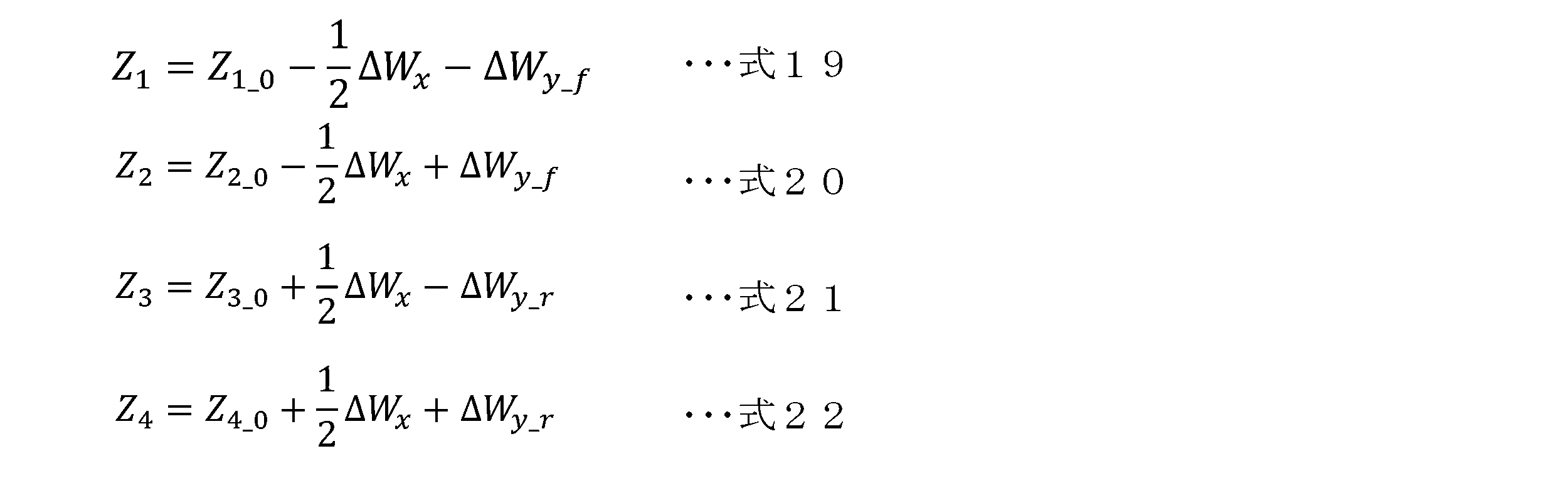
- the vertical load estimating unit 15 of the present embodiment also uses the longitudinal load movement amount ⁇ W x estimated by the load movement amount estimating unit 14 to estimate each vertical load Z 1 to Z 4 by the following equations 19 to 22. (calculate.
- the lateral force estimating unit 16 calculates each wheel based on the four vertical loads Z 1 to Z 4 estimated by the vertical load estimating unit 15, the lateral force Y f of the front wheel 2F, and the lateral force Y r of the rear wheel 2R. This is to estimate the lateral forces Y 1 to Y 4 of 2.
- the lateral force estimating section 16 estimates the lateral forces Y 1 to Y 4 of each wheel 2. This estimation result is used when estimating . Specifically, each of the lateral forces Y 1 to Y 4 is estimated (calculated) using equations 23 to 26 below.
- FIGS. 9 and 10 show flowchart examples executed in the control device 10 described above.
- the flowchart of FIG. 10 is a subflowchart of step S10 of the flowchart of FIG. This flowchart is executed, for example, at a predetermined calculation cycle when the main power source of the vehicle 1 is on or while the vehicle 1 is running.
- step S1 information on various sensors 21 to 23 is acquired.
- step S2 the roll angle ⁇ is acquired by the roll angle acquisition unit 13.
- Subsequent steps S3 to S6 are performed by the load movement amount estimating section 14.
- step S3 each lateral force Y f , Y r of the front and rear wheels 2F, 2R is estimated, then in step S4 the front wheel side load movement amount ⁇ W y_f is estimated, and in step S5 the rear wheel side load movement amount ⁇ W y_r is estimated, and in step S6, the longitudinal load movement amount ⁇ W x is estimated. Then, in step S7, the vertical load estimating section 15 estimates four vertical loads Z 1 to Z 4 , and in step S8, the lateral force estimating section 16 estimates four lateral forces Y 1 to Y 4 .
- steps S3 to S8 can also be considered as processing by the second acquisition unit 11B.
- step S9 the required torque N and the required yaw moment Q, which are control command values, are acquired, and in the subsequent step S10, the calculation processing of the braking/driving forces X 1 and X 2 of the front wheels 2F by the calculation unit 12 (subflow chart in FIG. ) will be implemented.
- step S11 initial values of variables (X FMAX , X RMAX , ⁇ FMAX , ⁇ RMAX , etc.) used in the calculation are defined.
- step S12 the first acquisition unit 11 acquires a signal defining the total braking/driving force X total and the total left/right braking/driving force difference ⁇ total .
- a signal may be obtained (calculated) by substituting the required torque N and the required yaw moment Q obtained in step S9 into Equation 1, for example.
- step S13 the upper limit value of the actuator is acquired.
- the upper limit value is each upper limit value of the front actuator and rear actuator that apply torque to each wheel 2, and is calculated by a control device different from the control device 10.
- step S14 if the total braking /driving force X total and total left and right braking/driving force difference ⁇ total are limited by upper limit values. Note that if the requested value does not exceed the upper limit value, no particular restriction is made in step S14.
- each constraint condition is expressed (calculated ) by a linear function F (X 1 , X 2 ) including at least one of the two variables X 1 and be done.
- the intersection points P I between the linear functions F are calculated, and the calculation results (X 1 X 2 coordinates of all the intersection points P I ) are stored in the memory device of the control device 10 as solution candidates.
- the coefficients (a 1 , a 2 , b 1 , b 2 , C) of the evaluation function J shown by Equation 7 are calculated. In calculating this coefficient, estimated values of the lateral forces Y 1 to Y 4 and vertical loads Z 1 to Z 4 of each wheel 2 acquired by the second acquisition unit 11B are used.
- step S18 the points of contact P C between the boundary and the isoline of the evaluation function J are calculated, and the calculation results (X 1 X 2 coordinates of all the points of contact P C ) are stored in the memory device of the control device 10 as solution candidates. be done.
- step S19 among the solution candidates stored in steps S16 and S18, candidates outside the feasible region S are excluded, and in step S20, the remaining solution candidates (that is, candidates within the feasible region S) are excluded.
- the value of the evaluation function J is calculated using the coefficients obtained in step S17, and the solution that calculates the smallest J is determined as the provisional solution.
- step S21 it is determined whether a solution P min that provides the apex (extreme value J min ) of the evaluation function J exists within the feasible region S. If the solution P min that gives the extreme value exists within the feasible region S, the process proceeds to step S22, and the solution P min that gives the extreme value is found as the minimized solution P. On the other hand, if the solution P min that gives the extreme value does not exist within the feasible region S, the process proceeds to step S23, and the provisional solution found in step S20 is found as the minimized solution P.
- the above-mentioned control device 10 is provided with a calculation section 12 as a calculation device that calculates a minimizing solution P that minimizes the evaluation function J while satisfying a predetermined constraint condition, without repeating calculations, regarding the predetermined evaluation function J.
- the calculation unit 12 sets at least one point on the boundary determined from the constraint conditions (intersection point P I or contact point P C ) as a solution candidate, and provisionally finds a solution that minimizes the evaluation function J from the solution candidates.
- a first calculating unit 12A that determines the solution and a second calculating unit 12A that calculates the solution P min that gives the extreme value of the evaluation function J from a predetermined formula, and specifies the minimized solution P based on the solution P min that gives the extreme value and the provisional solution. It has a calculation section 12B. According to such an arithmetic unit 12 (arithmetic device), it is possible to reduce the computational load when solving a constrained minimization problem.
- the braking/driving forces X 1 to X 4 are The calculation load can be reduced during calculation. This can contribute to simplifying the control configuration and reducing the cost of the entire vehicle. Further, since the control device 10 described above determines the braking/driving force that minimizes the sum of the loads on each wheel 2, it can also contribute to improving the controllability of vehicle motion control.
- the intersection point P I between boundaries expressed by linear functions and the contact point P C between the boundary and the isoline of the evaluation function J are calculated as solution candidates, and the feasible area The smallest solution among the plurality of candidates within S is determined as the provisional solution.
- the evaluation function J is minimized while satisfying the constraints at the point that takes the apex (extreme value J min ) of the graph of the evaluation function J (the solution P min that gives the extremum value), the intersection P I , or the contact point P One of C. Therefore, a feasible region S is set in the three-dimensional space, and a provisional solution is first determined from solution candidates (intersection point P I and contact point P C ).
- the above-mentioned calculation unit 12 specifies the minimized solution P based on the determined provisional solution and the solution P min that provides the extreme value of the evaluation function J. Specifically, if the solution P min that gives the extreme value is within the feasible region S, that solution P min is specified as the minimizing solution P, and if the solution P min that gives the extreme value is outside the feasible region S, the solution P min is specified as the minimizing solution P. Identify the solution as the minimized solution P. Therefore, according to the arithmetic unit 12 (arithmetic device), the minimization solution P can be determined by addition, subtraction, multiplication, and magnitude comparison, so the minimization solution P can be specified without repeated calculations, further reducing the calculation load. can do. Moreover, according to the control device 10 described above, since the calculation unit 12 is included, the calculation load can be similarly reduced.
- the constraint conditions include satisfying the required total braking/driving force of the vehicle 1 and satisfying the required total left/right braking/driving force difference of the vehicle 1, so that the appropriate braking/driving force can be adjusted.
- X 1 to X 4 can be calculated.
- the above-described control device 10 is provided with a vertical load estimating section 15 as a second obtaining section 11B that obtains estimated values of the vertical loads Z 1 to Z 4 of each wheel 2.
- the vertical loads Z 1 to Z 4 on each wheel 2 can be estimated.
- the vertical loads Z 1 to Z 4 of each wheel 2 can be estimated using a relatively simple method without adding any new sensors, and the estimated vertical loads Z 1 to Z 4 can be used to perform braking and driving. Forces X 1 to X 4 can be calculated. This also contributes to reducing the calculation load, simplifying the control configuration, and reducing the cost of the entire vehicle.
- the load movement amounts ⁇ W y_f and ⁇ W y_r of the front and rear wheels 2F and 2R are calculated based on the sensor values of the yaw rate r and the lateral acceleration A y . , Y r .
- the accuracy of estimating the vertical loads Z 1 to Z 4 can be improved.
- the longitudinal load movement amount ⁇ W x is estimated based on the longitudinal acceleration A x detected by the longitudinal acceleration sensor 23, and the vertical load is estimated using this longitudinal load movement amount ⁇ W x . Therefore, estimation accuracy can be further improved.
- the above-described control device 10 is provided with a lateral force estimating section 16 as a second obtaining section 11B that obtains estimated values of the lateral forces Y 1 to Y 4 of each wheel 2, and estimates the estimated values of the lateral forces Y 1 to Y 4 of each wheel 2 based on the vertical loads Z 1 to Z 4 .
- the lateral forces Y 1 to Y 4 by 2 are also estimated.
- the braking/driving forces X 1 -X 4 can be calculated using the estimated lateral forces Y 1 -Y 4 as well. This also contributes to reducing the calculation load, simplifying the control configuration, and reducing the cost of the entire vehicle.
- the configuration of the control device 10 described above is an example, and is not limited to the configuration described above.
- the vehicle 1 described above is provided with a front motor 3 and two rear motors 5 as drive sources, and is provided with a differential device 6 that amplifies the torque difference between the two rear motors 5 and transmits it to the rear wheels 2R.
- Sources are not limited to these.
- one motor may be mounted as a drive source, an engine may be mounted instead of or in addition to the motor, and the differential gear 6 may be omitted.
- the brake device is also not limited to the brake devices 4 and 7 described above. Note that if the vehicle 1 is equipped with an active stability control (ASC), the ASC may be activated according to the estimated value estimated by the control device 10 described above.
- ASC active stability control
- the above equations 10, 12, 14, 16 to 26 used by the control device 10 for estimation and calculation are examples, and are not limited to the above equations.
- the vertical load estimation unit 15 described above uses the longitudinal load movement amount ⁇ W x estimated by the load movement estimation unit 14 when estimating the vertical loads Z 1 to Z 4 .
- the amount may be omitted or a preset (estimated) value may be used.
- control device 10 mounted on the vehicle 1 includes the calculation unit 12 as a calculation device is illustrated, but the calculation device is installed in the vehicle 1 separately from the control device 10. It may also be applied to the vehicle 1.
- the computing device is applicable to any computing device that solves a constrained minimization problem.
- the number of constraints and the content of the evaluation function are not particularly limited either.
Landscapes
- Engineering & Computer Science (AREA)
- Physics & Mathematics (AREA)
- Mathematical Physics (AREA)
- General Physics & Mathematics (AREA)
- Automation & Control Theory (AREA)
- Theoretical Computer Science (AREA)
- Data Mining & Analysis (AREA)
- Transportation (AREA)
- Mechanical Engineering (AREA)
- Mathematical Analysis (AREA)
- Computational Mathematics (AREA)
- Mathematical Optimization (AREA)
- Pure & Applied Mathematics (AREA)
- Databases & Information Systems (AREA)
- Software Systems (AREA)
- General Engineering & Computer Science (AREA)
- Algebra (AREA)
- Human Computer Interaction (AREA)
- Regulating Braking Force (AREA)
- Control Of Driving Devices And Active Controlling Of Vehicle (AREA)
Abstract
所定の評価関数に関し、所定の制約条件を満たしつつ評価関数を最小とする最小化解を求める演算装置は、評価関数について、制約条件から求まる境界上の少なくとも一つの点を解の候補とし、この解の候補から評価関数を最小化する解を暫定解と定める第一演算部と、所定の式から評価関数の極値を与える解を算出すると共に、極値を与える解及び暫定解に基づき最小化解を特定する第二演算部と、を有する。演算装置は、繰り返し計算なく最小化解を求める。当該演算装置としての演算部(12)を持つ制御装置(10)では、車両(1)の総制駆動力と総左右制駆動力差と各車輪(2)の横力及び垂直荷重とに基づいて求めた最小化解を用いて、各車輪(2)の制駆動力を演算する。制約条件には、フロント及びリヤの各アクチュエータ(3~7)について、最大左右トルク差及び最大トルクを超えないことが含まれる。
Description
本件は、制約付き最小化問題を繰り返し計算なく解く演算装置と、この演算装置を用いた車両の制御装置に関する。
例えば、車両運動制御では、各車輪の駆動力及び制動力(以下、これらを総称して「制駆動力」ともいう)を常に把握し、走行路やドライバ要求に応じて各車輪に適切な制御量(例えば駆動力や制動力など)が付与されることが望まれる。制駆動力に限らず、車両状態を把握するためには車載センサの検出値を用いるが、すべての情報をセンサで検出することはできないため、所定の条件や数式(関数)を使った演算方法(推定方法)が採用される。演算方法としては、例えば、所定の制約条件を満たす範囲で、所定関数の最小化問題を繰り返し計算で解く手法がある(例えば特許文献1,2参照)。最小化問題を解くことで、例えば車両状態に応じた適切な制御量を求めることができる。
しかしながら、繰り返し計算により最小化問題を解く手法では、計算負荷が大きいという課題がある。この課題は、車両の分野に限らず、いずれの分野においても、制約付き最小化問題を解く場合に発生し得る課題である。
本件は、このような課題に鑑み案出されたもので、制約付き最小化問題を解く際の計算負荷を小さくすることを目的の一つとする。なお、この目的に限らず、後述する発明を実施するための形態に示す各構成により導かれる作用効果であって、従来の技術によっては得られない作用効果を奏することも本件の他の目的である。
本件は、このような課題に鑑み案出されたもので、制約付き最小化問題を解く際の計算負荷を小さくすることを目的の一つとする。なお、この目的に限らず、後述する発明を実施するための形態に示す各構成により導かれる作用効果であって、従来の技術によっては得られない作用効果を奏することも本件の他の目的である。
開示の演算装置及び車両の制御装置は、以下に開示する態様又は適用例として実現でき、上記の課題の少なくとも一部を解決する。
開示の演算装置は、所定の評価関数に関し、所定の制約条件を満たしつつ前記評価関数を最小とする最小化解を求める演算装置であって、前記評価関数について、前記制約条件から求まる境界上の少なくとも一つの点を解の候補とし、前記解の候補から前記評価関数を最小化する解を暫定解と定める第一演算部と、所定の式から前記評価関数の極値を与える解を算出すると共に、前記極値を与える解及び前記暫定解に基づき前記最小化解を特定する第二演算部と、を有し、繰り返し計算なく前記最小化解を求める。
開示の演算装置は、所定の評価関数に関し、所定の制約条件を満たしつつ前記評価関数を最小とする最小化解を求める演算装置であって、前記評価関数について、前記制約条件から求まる境界上の少なくとも一つの点を解の候補とし、前記解の候補から前記評価関数を最小化する解を暫定解と定める第一演算部と、所定の式から前記評価関数の極値を与える解を算出すると共に、前記極値を与える解及び前記暫定解に基づき前記最小化解を特定する第二演算部と、を有し、繰り返し計算なく前記最小化解を求める。
また、開示の車両の制御装置は、上記の演算装置としての演算部と、車両の総制駆動力及び総左右制駆動力差を規定する信号を取得する第一取得部と、前記車両の各車輪の横力及び垂直荷重の推定値又は実測値を取得する第二取得部と、を備える。前記演算部は、前記第一取得部で取得された前記信号、及び、前記第二取得部で取得された前記推定値又は実測値に基づいて求めた前記最小化解を用いて前記各車輪の制駆動力を演算するものである。前記評価関数は、前記各車輪の負担の総和を表す関数であり、前記制約条件には、前記車両の前輪の制駆動力を制御するフロントアクチュエータ、及び、前記車両の後輪の制駆動力を制御するリヤアクチュエータのそれぞれについて、最大左右トルク差及び最大トルクを超えないことが含まれる。
開示の演算装置によれば、制約条件から求まる境界上の少なくとも一つの点を解の候補とし、この解の候補から評価関数を最小化する解を暫定解として定める。また、これとは別に評価関数の極値を与える解を求め、極値を与える解及び暫定解に基づいて、最小化解を特定することで、繰り返し計算をすることなく、評価関数の最小化解を求めることができる。これにより、制約付き最小化問題を解く際の計算負荷を小さくすることができる。
また、開示の車両の制御装置によれば、上記の演算装置としての演算部により、繰り返し計算なく最小化解が求められ、この最小化解を用いて各車輪の制駆動力が演算されるため、制駆動力の演算に際し計算負荷を小さくすることができる。
図面を参照して、実施形態としての演算装置及び車両の制御装置について説明する。以下に示す実施形態はあくまでも例示に過ぎず、以下の実施形態で明示しない種々の変形や技術の適用を排除する意図はない。各実施形態の構成は、それらの趣旨を逸脱しない範囲で種々変形して実施することができる。また、必要に応じて取捨選択することができ、あるいは適宜組み合わせることができる。
演算装置は、所定の評価関数に関し、所定の制約条件を満たしつつ評価関数を最小とする最小化解を求めるものである。演算装置は、第一演算部と第二演算部とを有し、繰り返し計算することなく、評価関数を最小とする最小化解を求める。第一演算部は、評価関数について、制約条件から求まる境界上の少なくとも一つの点を解の候補とし、この解の候補から評価関数を最小化する解を暫定解と定める。また、第二演算部は、所定の式から評価関数の極値を与える解を算出すると共に、算出した極値を与える解と第一演算部で定められた暫定解とに基づいて、最小化解を特定する。つまり、本演算装置は、境界上の点(暫定解)と極値を与える解との二つに絞り込んで最小化解を特定するため、繰り返し計算なく最小化解の特定が可能となっている。
二つの変数X1,X2を用いた二変数関数で表現される評価関数Jを例示する。この評価関数Jが、X1軸とX2軸とJ軸とからなる三次元空間で下に凸の略長球面形状のグラフとなり、制約条件が複数設けられる場合、各制約条件を与える関数は、二つの変数X1,X2の少なくとも一方を含む一次関数で表現される。
この場合、演算装置の第一演算部は、交差する一次関数(境界)同士の交点を解の候補として演算すると共に、上記の三次元空間(X1-X2-J空間)において、一次関数で表される平面(境界)と接するように、評価関数Jの等値線が定められるときの、平面(境界)と等値線との接点を解の候補として演算する。さらに第一演算部は、制約条件をすべて満たす二つの変数X1,X2の集合を実行可能領域Sとし、実行可能領域S以内の解の候補のそれぞれを評価関数に代入して、算出された値が最小となる解の候補を、暫定解と定める。
また、演算装置の第二演算部は、評価関数の極値を与える解が実行可能領域S以内であれば、この極値を与える解を最小化解として特定する。反対に、評価関数の極値を与える解が実行可能領域S外であれば、第一演算部により定められた暫定解を最小化解として特定する。なお、上記の「境界」とは、制約条件から求まる実行可能領域Sの境界を意味し、「実行可能領域S以内」とは、実行可能領域Sの内側と実行可能領域Sの境界上を意味する。
演算装置で扱う評価関数は特に限られない。例えば、演算装置が車両に適用される場合には、車両の各車輪の負担の総和を表す評価関数が挙げられる。また、姿勢制御のためにアクチュエータで発生させる力の二乗和を評価関数にして、最小化する制御量を求めることで、エネルギー消費を少なく抑えることができるが、この評価関数を最小とする最小化解を求める際に演算装置を利用してもよい。
以下、演算装置が車両に適用される場合を例に挙げて、演算装置の構成と、車両の制御装置の構成について詳述する。なお、以下の説明では、車両の前進方向を前方(車両前方)とし、前方を基準に左右を定める。
以下、演算装置が車両に適用される場合を例に挙げて、演算装置の構成と、車両の制御装置の構成について詳述する。なお、以下の説明では、車両の前進方向を前方(車両前方)とし、前方を基準に左右を定める。
[1.装置構成]
本実施形態の制御装置10は、図1に例示する車両1に適用され、少なくとも車両1の各車輪2の制動力及び駆動力(以下「制駆動力」とも呼ぶ)を演算する演算装置としての機能を持ち、好ましくは、各車輪2の垂直荷重(接地荷重や輪荷重とも呼ばれる)及び横力を推定する機能を持つ。制御装置10は、車両1に搭載される電子制御装置(ECU,Electronic Control Unit)の一つで実現される装置である。制御装置10には、例えばCPU(Central Processing Unit),MPU(Micro Processing Unit)等のプロセッサ(マイクロプロセッサ)やROM(Read Only Memory),RAM(Random Access Memory),不揮発メモリ等が実装される。
本実施形態の制御装置10は、図1に例示する車両1に適用され、少なくとも車両1の各車輪2の制動力及び駆動力(以下「制駆動力」とも呼ぶ)を演算する演算装置としての機能を持ち、好ましくは、各車輪2の垂直荷重(接地荷重や輪荷重とも呼ばれる)及び横力を推定する機能を持つ。制御装置10は、車両1に搭載される電子制御装置(ECU,Electronic Control Unit)の一つで実現される装置である。制御装置10には、例えばCPU(Central Processing Unit),MPU(Micro Processing Unit)等のプロセッサ(マイクロプロセッサ)やROM(Read Only Memory),RAM(Random Access Memory),不揮発メモリ等が実装される。
プロセッサは、制御ユニット(制御回路)や演算ユニット(演算回路),キャッシュメモリ(レジスタ群)等を内蔵する演算処理装置である。また、ROM,RAM及び不揮発メモリは、プログラムや作業中のデータが格納されるメモリ装置である。制御装置10で実施される演算内容は、ファームウェアやアプリケーションプログラムとしてメモリに記録,保存されており、プログラムの実行時にはプログラムの内容がメモリ空間内に展開されて、プロセッサによって実行される。
本実施形態の車両1は、駆動源として、前輪2Fを駆動するフロントモータ3と、後輪2Rを駆動する二つのリヤモータ5とを備えた電動車両(EV;Electric Vehicle,HEV;Hybrid Electric Vehicle,PHEV;Plug-in Hybrid Electric Vehicle)であり、左右の後輪2Rにトルク差を付与する差動装置6をさらに備える。差動装置6は、二つのリヤモータ5のトルク差を増幅してから後輪2Rの各々にトルクを分配する機能を持つ動力分配装置である。
差動装置6は、ヨーコントロール機能(AYC機能)を持ったディファレンシャル機構であり、左後輪2RLに連結される車軸と右後輪2RRに連結される車軸との間に介装される。ヨーコントロール機能とは、左右後輪2Rの駆動力(駆動トルク)の分担割合を積極的に制御することでヨーモーメントを調節し、車両1の姿勢を安定させる機能である。差動装置6の内部には、遊星歯車機構や差動歯車機構などが内蔵される。なお、一対のリヤモータ5と差動装置6とを含む車両駆動装置は、DM-AYC(Dual-Motor Active Yaw Control)装置とも呼ばれる。
また、本実施形態の車両1は、制動装置として、前輪2Fを制動するフロントブレーキ装置4と、後輪2Rを制動するリヤブレーキ装置7とを備え、各車輪2が独立してブレーキ制御される。本実施形態のフロントブレーキ装置4には、ヨーコントロール機能(AYC機能)が備えられる。また、車両1には図示しない駆動用バッテリが搭載される。以下、前輪2Fの制駆動力を制御するフロントモータ3及びフロントブレーキ装置4を「フロントアクチュエータ」と総称し、後輪2Rの制駆動力を制御するリヤモータ5,差動装置6及びリヤブレーキ装置7を「リヤアクチュエータ」と総称する。
これらの装置3~7は、図示しない車載制御装置により個別制御される。例えば、フロントモータ3及びリヤモータ5を制御するモータ制御装置,フロントブレーキ装置4及びリヤブレーキ装置7を制御するブレーキ制御装置が車両1には搭載される。本実施形態では、制御装置10で演算された演算結果が各種制御装置に送出され、各装置3~7の制御に用いられる。なお、制御装置10に、各装置3~7を制御する機能が兼ね備えられていてもよい。
車両1には、車両1の各種情報を取得するためのセンサが設けられる。図1に示す例では、ヨーレイトセンサ21と、横加速度センサ22と、前後加速度センサ23とが設けられ、各センサ21~23が制御装置10に接続されている。ヨーレイトセンサ21(ヨーレイト検出手段)は、車両1の重心Gを通る鉛直軸回りの回転角速度をヨーレイトrとして検出するセンサである。本実施形態では、図1中に太矢印で示すように、ヨーレイトrは、車両1を上からみたときに重心Gの反時計回りが正の方向とされる。
横加速度センサ22(横加速度検出手段)及び前後加速度センサ23(前後加速度検出手段)は、車両1の重心Gにおける、横加速度Ay及び前後加速度Axをそれぞれ検出するセンサである。本実施形態では、図1中に太矢印で示すように、横加速度Ayは、重心Gから左向きが正の方向とされ、前後加速度Axは、重心Gから前方に向かう方向が正の方向とされる。各センサ21~23で検出された情報は、制御装置10に送出される。なお、これらのセンサ21~23の他、車両1には、例えば、アクセル開度センサ,ブレーキセンサ,車速センサや車輪速センサ,操舵角センサといった汎用のセンサが設けられる。
ヨーレイトrを検出する手段,横加速度Ayを検出する手段,前後加速度Axを検出する手段は、ヨーレイトセンサ21,横加速度センサ22,前後加速度センサ23に限られない。例えば、舵角や車体速Vに基づいて横加速度Ayを推定したり、当該推定した値や横加速度センサ22で検出した値を別のセンサ値に基づき補正したりすることで横加速度Ayを検出(取得)してもよい。同様に、ヨーレイトセンサ21で検出した値,前後加速度センサ23で検出した値を、別のセンサ値に基づき補正することでヨーレイトr,前後加速度Axを検出(取得)してもよい。このような場合には、推定部や補正部(制御装置の機能要素)が各検出手段となりうる。
[2.制御構成]
制御装置10は、車両1の総制駆動力Xtotal,総左右制駆動力差Δtotal,各車輪2の横力Y1~Y4及び垂直荷重Z1~Z4に基づいて、各車輪2の制駆動力X1~X4を演算するための機能要素として、第一取得部11B,第二取得部11B及び演算部12を備える。これらの要素は、制御装置10の機能を便宜的に分類して示したものである。これらの要素は、独立したプログラムとして各々を記述することができると共に、複数の要素を合体させた複合プログラムとして記述することもできる。各要素に相当するプログラムは、制御装置10のメモリや記憶装置に記憶され、プロセッサで実行される。なお、総制駆動力Xtotalは左右の制動力及び駆動力の合計であり、総左右制駆動力差Δtotalは、左の制動力及び駆動力と右の制動力及び駆動力との差の合計(前側と後側の差の合計)である。
制御装置10は、車両1の総制駆動力Xtotal,総左右制駆動力差Δtotal,各車輪2の横力Y1~Y4及び垂直荷重Z1~Z4に基づいて、各車輪2の制駆動力X1~X4を演算するための機能要素として、第一取得部11B,第二取得部11B及び演算部12を備える。これらの要素は、制御装置10の機能を便宜的に分類して示したものである。これらの要素は、独立したプログラムとして各々を記述することができると共に、複数の要素を合体させた複合プログラムとして記述することもできる。各要素に相当するプログラムは、制御装置10のメモリや記憶装置に記憶され、プロセッサで実行される。なお、総制駆動力Xtotalは左右の制動力及び駆動力の合計であり、総左右制駆動力差Δtotalは、左の制動力及び駆動力と右の制動力及び駆動力との差の合計(前側と後側の差の合計)である。
本実施形態の制御装置10は、制駆動力X1~X4の演算で用いる各車輪2の横力Y1~Y4及び垂直荷重Z1~Z4を演算する機能を併せ持つ。具体的には、制御装置10は、垂直荷重Z1~Z4を演算するための機能要素として、ロール角取得部13,荷重移動量推定部14及び垂直荷重推定部15を備え、横力Y1~Y4を演算するための機能要素として、横力推定部16を備える。これらの要素も、上記の要素11A,11B,12と同様、制御装置10の機能を便宜的に分類して示したものである。
制駆動力X1~X4,横力Y1~Y4及び垂直荷重Z1~Z4を示す符号では、左前輪2FL,右前輪2FR,左後輪2RL,右後輪2RRの順に、下付きの数字1~4を付す。
以下の説明では、まず、制駆動力X1~X4の演算に関して詳述し、次いで、横力Y1~Y4及び垂直荷重Z1~Z4の演算に関して詳述する。
以下の説明では、まず、制駆動力X1~X4の演算に関して詳述し、次いで、横力Y1~Y4及び垂直荷重Z1~Z4の演算に関して詳述する。
[2-1.制駆動力の演算]
第一取得部11Aは、車両1の総制駆動力Xtotal及び総左右制駆動力差Δtotalを規定する信号を取得するものである。本実施形態の第一取得部11Aは、要求トルクN及び要求ヨーモーメントQを取得し、下記の式1より、要求トルクNから総制駆動力Xtotalを求めると共に、要求ヨーモーメントQから総左右制駆動力差Δtotalを求め、それぞれを規定する信号として取得する。なお、式1中のRはタイヤ半径,Tはトレッドである。
第一取得部11Aは、車両1の総制駆動力Xtotal及び総左右制駆動力差Δtotalを規定する信号を取得するものである。本実施形態の第一取得部11Aは、要求トルクN及び要求ヨーモーメントQを取得し、下記の式1より、要求トルクNから総制駆動力Xtotalを求めると共に、要求ヨーモーメントQから総左右制駆動力差Δtotalを求め、それぞれを規定する信号として取得する。なお、式1中のRはタイヤ半径,Tはトレッドである。

要求トルクN及び要求ヨーモーメントQは、例えば制御装置10とは別の制御装置にて演算される制御指令値であり、ドライバ操作(アクセル開度,シフトポジション,走行モード等)及び車両状態に基づいて算出される。あるいは、制御装置10において、要求トルクN及び要求ヨーモーメントQを演算し、第一取得部11Aにて総制駆動力Xtotal及び総左右制駆動力差Δtotalを規定する信号を取得してもよい。なお、車両1の総制駆動力Xtotal及び総左右制駆動力差Δtotalを規定する信号の取得方法はこれに限られない。例えば、直接的に総制駆動力Xtotal及び総左右制駆動力差Δtotalを規定する信号を取得してもよいし、総制駆動出力及び総左右制駆動力出力差を取得して、総制駆動力Xtotal及び総左右制駆動力差Δtotalを計算してもよい。
第二取得部11Bは、車両1の各車輪2の横力Y1~Y4及び垂直荷重Z1~Z4の推定値又は実測値を取得するものである。本実施形態の制御装置10では、第二取得部11Bとしての、垂直荷重推定部14及び横力推定部15が設けられる。すなわち、本実施形態の第二取得部11Bは、横力Y1~Y4及び垂直荷重Z1~Z4の推定値を取得する。なお、後述する横力Y1~Y4及び垂直荷重Z1~Z4の推定処理を省略する場合には、第二取得部11Bは、横力Y1~Y4及び垂直荷重Z1~Z4の実測値を取得すればよい。
演算部12は、第一取得部11Aで取得された総制駆動力Xtotal及び総左右制駆動力差Δtotalを規定する信号と、第二取得部11Bで取得された横力Y1~Y4及び垂直荷重Z1~Z4の推定値又は実測値とに基づき、各車輪2の制駆動力X1~X4を演算(推定)する。本実施形態の制御装置10では、この演算部12に、上述した繰り返し計算なく最小化解の特定が可能な演算装置の機能が設けられる。言い換えると、制御装置10は、上述した演算装置としての演算部12を備える。
演算部12は、所定の評価関数Jに関し、所定の制約条件を満たしつつ評価関数Jを最小とする最小化解を繰り返し計算なく求める。そして、求めた最小化解を制駆動力X1~X4の演算で用いる。本実施形態の評価関数Jは、各車輪2の負担の総和を表す関数として与えられる。具体的には、下記の式2で示すように、各車輪2について、制駆動力の二乗及び横力の二乗の和を垂直荷重の二乗で除した値(各車輪2で発生している摩擦力と摩擦力との比)を算出し、この値を四輪分(四つ)加算した値(すなわち、各車輪2で発生している摩擦力と垂直荷重との比の二乗和)で表現される。このように、評価関数Jが最も小さくなる制駆動力X1~X4を求めることで、タイヤ滑りを防止可能となる。

本実施形態の制御装置10では、下記の四つの制約条件が設けられる。
条件1.車両1の要求総制駆動力を満たすこと
条件2.車両1の要求総左右制駆動力差を満たすこと
条件3.フロントアクチュエータの最大左右トルク差及び最大トルクを超えないこと
条件4.リヤアクチュエータの最大左右トルク差及び最大トルクを超えないこと
条件1.車両1の要求総制駆動力を満たすこと
条件2.車両1の要求総左右制駆動力差を満たすこと
条件3.フロントアクチュエータの最大左右トルク差及び最大トルクを超えないこと
条件4.リヤアクチュエータの最大左右トルク差及び最大トルクを超えないこと
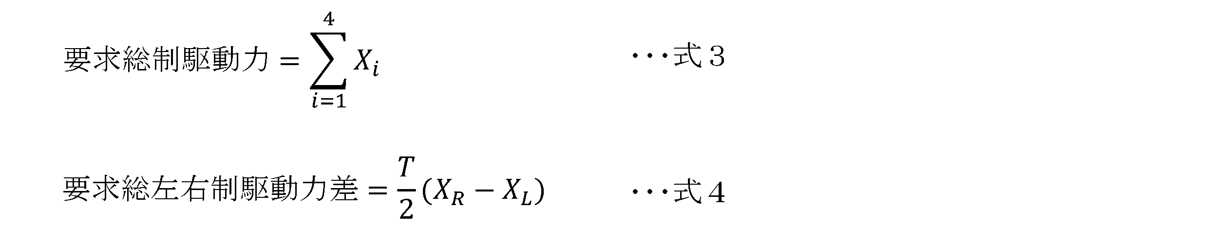
制約条件1及び2は、下記の式3及び4でそれぞれ表される。式4中のXLは左制駆動力(XL=X1+X3)であり、XRは右制駆動力(XR=X2+X4)である。
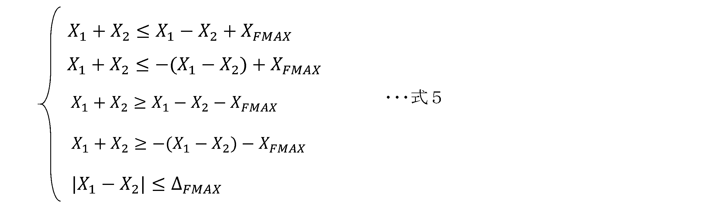
制約条件3は、下記の五つの式(まとめて「式5」とする)で表される。式5中のXFMAXは前側の最大制駆動力の絶対値であり、ΔFMAXは前側の最大制駆動力差の絶対値であって、いずれも制御装置10で演算されてもよいし、制御装置10とは別の制御装置にて演算されてもよい。制約条件3を与える関数(境界)は、下記の式5に示す通り、二つの変数X1,X2の少なくとも一方を含む一次関数F(X1,X2)で表現される。
制約条件4は、下記の四つの式(まとめて「式6」とする)で表される。式6中のXRMAXは後側の最大制駆動力の絶対値であり、ΔRMAXは後側の最大制駆動力差の絶対値であって、いずれも制御装置10で演算されてもよいし、制御装置10とは別の制御装置にて演算されてもよい。
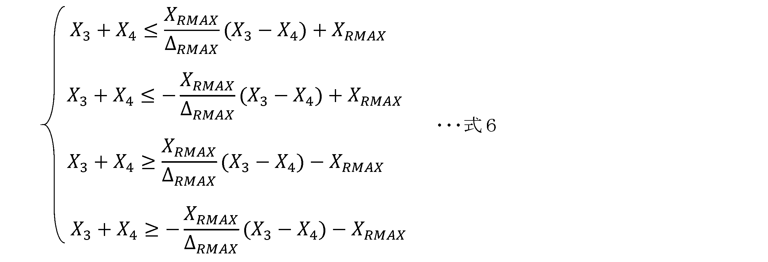
なお、XL=X1+X3,XR=X2+X4であるため、式3,式4の関係を式6に代入すると、式6から後輪2Rの制駆動力X3,X4を消去できる。これにより、制約条件4の境界も、下記の式6′に示す通り、二つの変数X1,X2の少なくとも一方を含む一次関数F(X1,X2)で表現される。

また、XL=X1+X3,XR=X2+X4の関係を式2に代入すると、式2から後輪2Rの制駆動力X3,X4を消去できる。
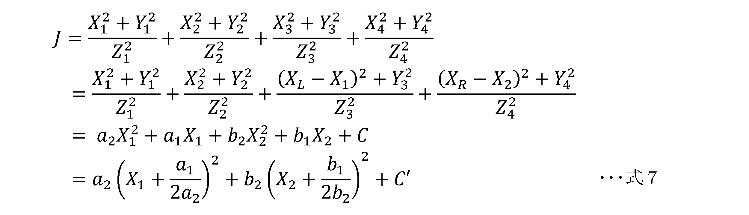
なお、総制駆動力Xtotal=XL+XR,総左右制駆動力差Δtotal=XR-XLであるため、これら2式から、左制駆動力XL及び右制駆動力XRは、下記の式8のとおり、総制駆動力Xtotal及び総左右制駆動力差Δtotalで表される。

上記の式7のように、評価関数Jは、前輪2Fの各制駆動力を変数X1,X2とした二変数関数で表現される。図2に示すように、評価関数Jは、X1軸とX2軸とJ軸とからなる三次元空間で下に凸の略長球面形状(お椀形状)のグラフとなる。具体的には、評価関数Jは、(X1,X2)=((-a1/2a2),(-b1/2b2))を対称軸に持つ曲面となり、J軸に関する等値線(J軸に直交する断面形状)が楕円状となる。制約条件がない場合の評価関数Jの最小化解P(X1,X2)は、グラフの頂点(極値)をとる点の座標{(-a1/2a2),(-b1/2b2)}となる。しかし実際には、上記の制約条件があるため、演算部12は、下記の手法により、所定の制約条件を満たす点から、評価関数Jを最小とするもの(最小化解P)を繰り返し計算なく求める。
演算装置としての演算部12は、第一演算部12A,第二演算部12B及び第三演算部12Cを有する。第一演算部12Aは、評価関数Jについて、制約条件から求まる境界上の少なくとも一つの点を解の候補とし、解の候補から評価関数Jを最小化する解を暫定解と定める。なお、境界は、制約条件から求まる実行可能領域Sの境界(境界線や境界面)である。
第二演算部12Bは、所定の式から評価関数Jの極値Jminを算出すると共に、この極値Jminをとる点Pmin(以下、「極値を与える解Pmin」という)と第一演算部12Aで定めた暫定解とに基づいて、最小化解Pを特定する。第三演算部12Cは、最小化解Pを用いて各車輪2の制駆動力X1~X4を算出する。以下、評価関数Jの最小化解Pの求め方を、図3~図5を用いて説明する。
図3~図5は、図2のグラフをJ軸の正方向(図中上)からX1X2平面(X1軸及びX2軸の平面)に向かって見下ろした図である。図3~図5中の楕円は評価関数Jの等値線を示し、極値Jminは評価関数Jのグラフの頂点である。また、図中の太破線は、制約条件を与える一次関数(直線F)で定義される境界である。これは、X1X2平面でみれば直線であるが、図2のように三次元空間(X1-X2-J空間)で考えれば、J軸に平行な平面で表される。また、図中のドット模様で囲んだ実行可能領域Sは、全ての制約条件を満足する点(X1,X2)の集合であり、求めたい最小化解Pは、この実行可能領域S以内に存在する。なお、図3~図5の楕円や直線は一例である。
第一演算部12Aは、交差する一次関数(直線F)同士の交点PIと、上記平面(境界)と評価関数Jの等値線との接点PCとを、解の候補としてそれぞれ演算する。なお、接点PCは、下記の式9で定義される楕円Eが直線Fと接するときの接点である。式9中のEは任意実数である。

なお、図3~図5では、一部の交点PI及び接点PCに符号を付しているが、第一演算部12Aは全ての交点PI及び接点PCを演算して解の候補とする。交点PIは、X1X2平面上で直線同士が交わる点であるが、接点PCは、X1-X2-J空間において、一次関数(境界)と接するように、評価関数Jの等値線が定められるときの、境界と等値線との接点である。
第一演算部12Aは、さらに、上記の実行可能領域Sを設定し、実行可能領域S以内の解の候補(交点PI,接点PC)のそれぞれを評価関数Jに代入して〔例えば、交点PIの座標(X1,X2)の値を式7に代入して〕、Jの値を計算する。そして、算出した値が最小となる解の候補(X1,X2)を暫定解と定める。
第二演算部12Bは、上記のように定められた暫定解と、評価関数Jの極値を与える解Pminとを比較し、いずれか一方を最小化解Pとして特定する。具体的には、図3に示すように、極値を与える解Pminが実行可能領域S以内(実行可能領域Sの内側又は実行可能領域Sの境界上で)である場合には、極値を与える解Pminが最小化解Pであると特定する(最小化解P=Pmin)。一方、図4及び図5に示すように、極値を与える解Pminが実行可能領域S外である場合には、暫定解(交点PI又は接点PC)が最小化解Pであると特定する(最小化解P=PI又はPC)。
第三演算部12Cは、特定された最小化解P(X1,X2)を、左前輪2FLの制駆動力X1及び右前輪2FRの制駆動力X2とする。また、XL=X1+X3,XR=X2+X4であるため、第三演算部12Cは、最小化解P(X1,X2)及び上記の式8の関係から、左後輪2RLの制駆動力X3及び右後輪2RRの制駆動力X4を算出する。
[2-2.垂直荷重及び横力の推定]
次に、制御装置10で実施される横力Y1~Y4及び垂直荷重Z1~Z4の推定に関して説明する。なお、本実施形態では、ここで推定される横力Y1~Y4及び垂直荷重Z1~Z4の値が、上記の制駆動力X1~X4の推定に用いられる場合を例示しているが、推定された横力Y1~Y4及び垂直荷重Z1~Z4の値は、様々な車両運動制御(例えば、パワーステアリング装置の制御,AFSやARS等の舵角制御,アクティブサスペンションや報知装置の制御等)に利用可能である。また、以下に説明する方法以外の手法で、推定,取得した横力Y1~Y4及び垂直荷重Z1~Z4の値を使って上記の制駆動力X1~X4の推定を行ってもよい。
次に、制御装置10で実施される横力Y1~Y4及び垂直荷重Z1~Z4の推定に関して説明する。なお、本実施形態では、ここで推定される横力Y1~Y4及び垂直荷重Z1~Z4の値が、上記の制駆動力X1~X4の推定に用いられる場合を例示しているが、推定された横力Y1~Y4及び垂直荷重Z1~Z4の値は、様々な車両運動制御(例えば、パワーステアリング装置の制御,AFSやARS等の舵角制御,アクティブサスペンションや報知装置の制御等)に利用可能である。また、以下に説明する方法以外の手法で、推定,取得した横力Y1~Y4及び垂直荷重Z1~Z4の値を使って上記の制駆動力X1~X4の推定を行ってもよい。
ロール角取得部13は、車両1のロール角θを取得するものである。ロール角θの取得手法は特に限られず、上記のセンサ21~23と同様、ロール角θを検出可能なセンサを設け、センサ値やセンサ値の補正値をロール角θとして取得してもよい。あるいは、センサ値と車両諸元とに基づいてロール角θを推定することでその値(ロール角θ)を取得してもよい。ここでは、後者の手法、すなわち、ロール角θを推定して取得する方法の一例を説明する。
ロール角取得部13は、横加速度センサ22により検出された横加速度Ayと、前輪2Fに関する前輪ロール減衰係数cf及び後輪2Rに関する後輪ロール減衰係数crの和である車両ロール減衰係数c(=cf+cr)とに基づいて、車両1のロール角θを推定する。車両ロール減衰係数cとは、図6に示すように、ロール方向の減衰係数であり、前輪ロール減衰係数cfは、図7に示すように、ロール方向の減衰係数のうち前軸で受け持つ分であり、後輪ロール減衰係数crは、図8に示すように、ロール方向の減衰係数のうち後軸で受け持つ分である。なお、図6~図8は車両1を振り子に見立ててモデル化したもの(荷重移動モデル)であり、図6は車両背面から見たモデル、図7は前軸の中心線で切断したモデル、図8は後軸の中心線で切断したモデルである。
本実施形態のロール角取得部13は、図6のモデルを使用し、下記の式10によりロール角θを推定(算出)する。式10中のmは車両質量,hはロール半径,Ixはロール慣性モーメント,kは車両ロール剛性,gは重力加速度であり、いずれも固定値である。なお、前後輪のロール減衰係数cf,crは、例えば、ロール角速度に対する定数として予めマップ化されており、ロール角速度をマップに適用することで取得される。また、ロール角速度は、例えば推定したロール角θを微分することで求めてもよいし、センサ値でもよい。車両ロール剛性kは、前輪2Fに関する前輪ロール剛性kf及び後輪2Rに関する後輪ロール剛性krの和である。なお、前後輪のロール剛性kf,krは固定値であり、sはラプラス演算子である。

荷重移動量推定部14は、前輪2Fの左右輪間における荷重移動量ΔWy_f(以下、前輪側荷重移動量ΔWy_fという)と、後輪2Rの左右輪間における荷重移動量ΔWy_r(以下、後輪側荷重移動量ΔWy_rという)とをそれぞれ推定するものである。前輪側荷重移動量ΔWy_fは、ロール角取得部13で取得されたロール角θと、前輪2Fの横力Yfと、前輪ロール減衰係数cfと、前輪ロール剛性kfとに基づいて推定される。同様に、後輪側荷重移動量ΔWy_rは、ロール角取得部13で取得されたロール角θと、後輪2Rの横力Yrと、後輪ロール減衰係数crと、後輪ロール剛性krとに基づいて推定される。
なお、前輪2Fの横力Yfは、左前輪2FLの横力Y1と右前輪2FRの横力Y2との和(Yf=Y1+Y2)であり、後輪2Rの横力Yrは、左後輪2RLの横力Y3と右後輪2RRの横力Y4との和(Yr=Y3+Y4)である。前後輪2F,2Rの各横力Yf,Yrは、後述するように、荷重移動量推定部14で推定された値を用いることが好ましい。
本実施形態の荷重移動量推定部14は、図7のモデルを使用し、前輪2Fのロールセンターまわりに働くモーメントの釣り合い式である下記の式11から、前輪側荷重移動量ΔWy_fを推定する。具体的には、式10を前輪側荷重移動量ΔWy_fについて解き、ラプラス変換した式12を用いて、前輪側荷重移動量ΔWy_fを推定(算出)する。
式11,12中のTはトレッド(フロントトレッド),hfは前輪2Fのロールセンター高さ(地面からロールセンターまでの高さ)であり、いずれも固定値である。また、式11中のZ1_0及びZ2_0は車両停止状態での左右前輪2FL,2FRの垂直荷重である。これらの値Z1_0,Z2_0は、例えば、予め定めた固定値でもよいし、サスペンションのストロークセンサ値などから推定した推定値であってもよい。なお、これらの値Z1_0,Z2_0は必ずしも互いに等しくなくてよい。

後輪2Rについても同様である。すなわち、荷重移動量推定部14は、図8のモデルを使用し、後輪2Rのロールセンターまわりに働くモーメントの釣り合い式である下記の式12から、後輪側荷重移動量ΔWy_rを推定する。具体的には、式13を後輪側荷重移動量ΔWy_rについて解き、ラプラス変換した式14を用いて、後輪側荷重移動量ΔWy_rを推定(算出)する。式13,14中のTはトレッド(リアトレッド),hrは後輪2Rのロールセンター高さであり、いずれも固定値である。また、式13中のZ3_0及びZ4_0は、車両停止状態での左右後輪2RL,2RRの垂直荷重であり、前輪側と同様である。

本実施形態の荷重移動量推定部14は、上記の通り、前後輪2F,2Rの各横力Yf,Yrを推定する。具体的には、ヨーレイトセンサ21で検出されたヨーレイトrと横加速度センサ22で検出された横加速度Ayとに基づいて、前後輪2F,2Rの各横力Yf,Yrを推定する。そして、上記の荷重移動量ΔWy_f,ΔWy_rの推定に際し、推定した各横力Yf,Yrを使用する。
本実施形態の荷重移動量推定部14は、下記の式15を横力Yf,Yrについて解いた式16,17を用いて、前後輪2F,2Rの各横力Yf,Yrをそれぞれ推定する。なお、当該推定は、上記の荷重移動量ΔWy_f,ΔWy_rの推定と同じ演算周期で行う。
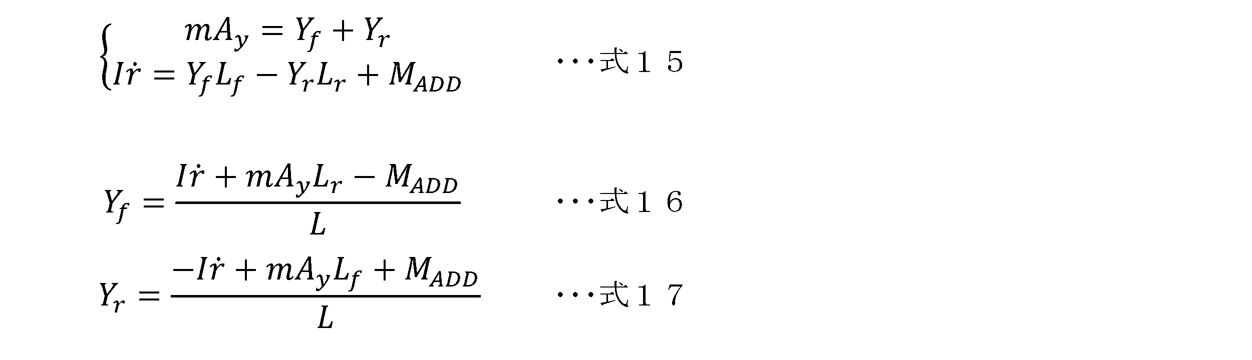
式15~17中のLfは前車軸と重心Gとの前後方向の距離,Lrは後車軸と重心Gとの前後方向の距離,Lはホイールベース(前後車軸の距離)であり、いずれも固定値である。また、MADDは制駆動力差によるヨーモーメントであり、本実施形態では、制御装置10とは別の制御装置にて演算される制御要求値である。ただし、横力Yf,Yrの推定方法はこれに限られず、例えば、荷重移動量ΔWy_f,ΔWy_rの推定とは異なる演算周期で推定してもよいし、ヨーモーメントMADDに代えて又は加えて、別のパラメータを考慮してもよい。
また、本実施形態の荷重移動量推定部14は、前後加速度センサ23で検出された前後加速度Axに基づいて、下記の式18により前後軸の荷重移動量ΔWx(以下、前後荷重移動量ΔWxという)を推定する。前後荷重移動量ΔWxは、次に説明する垂直荷重Z1~Z4の推定において用いられる。なお、式18中のhcgは重心高さである。

垂直荷重推定部15は、荷重移動量推定部14で推定された前輪側荷重移動量ΔWy_f及び後輪側荷重移動量ΔWy_rに基づいて、各車輪2の垂直荷重Z1~Z4を推定するものである。具体的には、車両停止状態での各車輪2の垂直荷重Z1_0~Z4_0に、走行状態に起因した荷重移動量分を加減算することで各車輪2の垂直荷重Z1~Z4を推定する。本実施形態の垂直荷重推定部15は、荷重移動量推定部14で推定された前後荷重移動量ΔWxも使用して、下記の式19~22により、各垂直荷重Z1~Z4を推定(算出)する。
横力推定部16は、垂直荷重推定部15で推定された四つの垂直荷重Z1~Z4と、前輪2Fの横力Yfと後輪2Rの横力Yrとに基づいて、各車輪2の横力Y1~Y4を推定するものである。本実施形態では、前後輪2F,2Rの各横力Yf,Yrが荷重移動量推定部14において推定されるため、横力推定部16は、各車輪2の横力Y1~Y4の推定に際し、この推定結果を用いる。具体的には、下記の式23~26により、各横力Y1~Y4を推定(算出)する。

[3.フローチャート]
図9及び図10に、上述した制御装置10において実施されるフローチャート例を示す。図10のフローチャートは、図9のフローチャートのステップS10のサブフローチャートである。このフローチャートは、例えば、車両1の主電源がオンの場合や走行中に所定の演算周期で実施される。まず、ステップS1において、各種センサ21~23の情報が取得される。ステップS2では、ロール角取得部13によりロール角θが取得される。続くステップS3~S6は、荷重移動量推定部14により実施される。
図9及び図10に、上述した制御装置10において実施されるフローチャート例を示す。図10のフローチャートは、図9のフローチャートのステップS10のサブフローチャートである。このフローチャートは、例えば、車両1の主電源がオンの場合や走行中に所定の演算周期で実施される。まず、ステップS1において、各種センサ21~23の情報が取得される。ステップS2では、ロール角取得部13によりロール角θが取得される。続くステップS3~S6は、荷重移動量推定部14により実施される。
まず、ステップS3において、前後輪2F,2Rの各横力Yf,Yrが推定され、次いで、ステップS4において前輪側荷重移動量ΔWy_fに推定され、ステップS5において後輪側荷重移動量ΔWy_rが推定され、ステップS6において前後荷重移動量ΔWxが推定される。そして、ステップS7では、垂直荷重推定部15により四つの垂直荷重Z1~Z4が推定され、ステップS8では、横力推定部16により四つの横力Y1~Y4が推定される。これらのステップS3~S8は、第二取得部11Bの処理とも捉えられる。
ステップS9では、制御指令値である要求トルクN及び要求ヨーモーメントQが取得され、続くステップS10において、演算部12による前輪2Fの制駆動力X1,X2の演算処理(図10のサブフローチャート)が実施される。
図10に示すように、ステップS11では、演算で用いられる変数(XFMAX,XRMAX,ΔFMAX,ΔRMAXなど)の初期値が定義される。ステップS12では、第一取得部11により総制駆動力Xtotal及び総左右制駆動力差Δtotalを規定する信号が取得される。このステップS12では、例えば、ステップS9で取得された要求トルクN及び要求ヨーモーメントQを式1に代入することで信号が取得(算出)されてよい。
ステップS13では、アクチュエータの上限値が取得される。上限値とは、各車輪2にトルクを与えるフロントアクチュエータ及びリヤアクチュエータの各上限値であり、制御装置10とは別の制御装置において演算される。ステップS14では、ステップS12で取得された総制駆動力Xtotal及び総左右制駆動力差Δtotal(要求値)が、ステップS13で取得された上限値を超えている場合に、総制駆動力Xtotal及び総左右制駆動力差Δtotalを上限値で制限する。なお、要求値が上限値を超えていなければ、ステップS14では特に制限はしない。
ステップS15では、各制約条件が、上記の式5及び式6′で示すように、二つの変数X1,X2の少なくとも一方を含む一次関数F(X1,X2)で表現(計算)される。続くステップS16では、一次関数F同士の交点PIが演算され、演算結果(全ての交点PIのX1X2座標)が解の候補として制御装置10のメモリ装置に記憶される。ステップS17では、式7で示される評価関数Jの係数(a1,a2,b1,b2,C)が演算される。この係数の計算において、第二取得部11Bで取得された各車輪2の横力Y1~Y4及び垂直荷重Z1~Z4の推定値が用いられる。
ステップS18では、境界と評価関数Jの等値線との接点PCが演算され、演算結果(全ての接点PCのX1X2座標)が解の候補として制御装置10のメモリ装置に記憶される。ステップS19では、ステップS16及びS18で記憶された解の候補のうち、実行可能領域S外の候補が除外され、ステップS20において、残った解の候補(すなわち、実行可能領域S以内の候補)について、ステップS17で求めた係数を使って評価関数Jの値が算出されて、最も小さいJを算出した解が暫定解として定められる。
ステップS21では、評価関数Jの頂点(極値Jmin)を与える解Pminが実行可能領域S以内に存在するか否かが判定される。極値を与える解Pminが実行可能領域S以内に存在する場合には、ステップS22に進み、極値を与える解Pminが最小化解Pとして求められる。一方、極値を与える解Pminが実行可能領域S以内に存在しない場合には、ステップS23に進み、ステップS20で求められた暫定解が最小化解Pとして求められる。
以上のサブフローチャートにより前輪2Fの制駆動力X1,X2が求められたら、図9のステップS24に進み、後輪2Rの制駆動力X3,X4が求められて、このフローチャートをリターンする。
[4.効果]
上述した制御装置10には、所定の評価関数Jに関し、所定の制約条件を満たしつつ評価関数Jを最小とする最小化解Pを繰り返し計算なく求める演算装置としての演算部12が設けられる。演算部12は、評価関数Jについて、制約条件から求まる境界上の少なくとも一つの点(交点PI又は接点PC)を解の候補とし、解の候補から評価関数Jを最小化する解を暫定解と定める第一演算部12Aと、所定の式から評価関数Jの極値を与える解Pminを算出すると共に、極値を与える解Pmin及び暫定解に基づき最小化解Pを特定する第二演算部12Bとを有する。このような演算部12(演算装置)によれば、制約付き最小化問題を解く際の計算負荷を小さくすることができる。
上述した制御装置10には、所定の評価関数Jに関し、所定の制約条件を満たしつつ評価関数Jを最小とする最小化解Pを繰り返し計算なく求める演算装置としての演算部12が設けられる。演算部12は、評価関数Jについて、制約条件から求まる境界上の少なくとも一つの点(交点PI又は接点PC)を解の候補とし、解の候補から評価関数Jを最小化する解を暫定解と定める第一演算部12Aと、所定の式から評価関数Jの極値を与える解Pminを算出すると共に、極値を与える解Pmin及び暫定解に基づき最小化解Pを特定する第二演算部12Bとを有する。このような演算部12(演算装置)によれば、制約付き最小化問題を解く際の計算負荷を小さくすることができる。
また、上述した制御装置10によれば、このように演算された最小化解Pを、各車輪2の制駆動力X1~X4の演算に用いることから、制駆動力X1~X4の演算に際し計算負荷を小さくすることができる。これにより、制御構成の簡素化や車両全体のコスト抑制に寄与できる。また、上述した制御装置10では、各車輪2の負担の総和を最小化する制駆動力を求めることから、車両運動制御の制御性向上に寄与することもできる。
上記の演算部12では、一次関数で表現される境界同士の交点PIと、境界と評価関数Jの等値線との接点PCとがそれぞれ解の候補として演算されると共に、実行可能領域S以内の複数の候補の中で最小の解が暫定解と定められる。すなわち、制約条件を満足しつつ評価関数Jが最小となるのは、評価関数Jのグラフの頂点(極値Jmin)をとる点(極値を与える解Pmin)か交点PIか接点PCのいずれか一つである。そこで、三次元空間に実行可能領域Sを設定し、まずは解の候補(交点PIと接点PC)の中から暫定解を定める。
さらに、上記の演算部12では、定めた暫定解と評価関数Jの極値を与える解Pminとに基づき最小化解Pが特定される。具体的には、極値を与える解Pminが実行可能領域S以内であるならその解Pminを最小化解Pとして特定し、極値を与える解Pminが実行可能領域S外であるなら暫定解を最小化解Pとして特定する。したがって、上記の演算部12(演算装置)によれば、加減乗除と大小比較とで最小化解Pを求めることができるため、繰り返し計算をすることなく最小化解Pを特定でき、計算負荷をより低減することができる。また、上述した制御装置10によれば、この演算部12を含むことから、同様に計算負荷を低減することができる。
なお、上述した制御装置10では、制約条件に、車両1の要求総制駆動力を満たすこと、及び、車両1の要求総左右制駆動力差を満たすことが含まれるため、適切な制駆動力X1~X4を演算することができる。
また、上述した制御装置10では、各車輪2の垂直荷重Z1~Z4の推定値を取得する第二取得部11Bとしての垂直荷重推定部15が設けられ、車両1に標準装備される汎用センサ(ヨーレイトセンサ21及び横加速度センサ22)を使用して、各車輪2の垂直荷重Z1~Z4を推定することができる。すなわち、新たなセンサ等を追加することなく、比較的簡素な手法で、各車輪2の垂直荷重Z1~Z4を推定でき、この推定された垂直荷重Z1~Z4を使って制駆動力X1~X4を演算することができる。これによっても、計算負荷の抑制,制御構成の簡素化,車両全体のコスト抑制に寄与できる。
上記の制御装置10では、前後輪2F,2Rの荷重移動量ΔWy_f,ΔWy_rが、センサ値であるヨーレイトr及び横加速度Ayに基づき推定された前後輪2F,2Rの各横力Yf,Yrを使って推定される。これにより、垂直荷重Z1~Z4の推定精度を向上させることができる。
また、上記の制御装置10では、前後加速度センサ23で検出された前後加速度Axに基づき、前後荷重移動量ΔWxが推定され、この前後荷重移動量ΔWxを使用して垂直荷重が推定されることから、推定精度をより高めることができる。
また、上記の制御装置10では、前後加速度センサ23で検出された前後加速度Axに基づき、前後荷重移動量ΔWxが推定され、この前後荷重移動量ΔWxを使用して垂直荷重が推定されることから、推定精度をより高めることができる。
上述した制御装置10では、各車輪2の横力Y1~Y4の推定値を取得する第二取得部11Bとしての横力推定部16が設けられ、垂直荷重Z1~Z4に基づき車輪2ごとの横力Y1~Y4も推定される。そして、ここで推定された横力Y1~Y4も使って制駆動力X1~X4を演算することができる。これによっても、計算負荷の抑制,制御構成の簡素化,車両全体のコスト抑制に寄与できる。また、各車輪2の左右方向及び上下方向の力を推定することで、様々な車両運動制御に活用しやすくなる。
例えば、車両運動制御の一つであるスピン挙動の抑制制御に活用すれば、各車輪2の制駆動力を適切に設定可能となり、車輪2の横滑りを効果的に抑制しうる。
例えば、車両運動制御の一つであるスピン挙動の抑制制御に活用すれば、各車輪2の制駆動力を適切に設定可能となり、車輪2の横滑りを効果的に抑制しうる。
[5.その他]
上述した制御装置10の構成は一例であって、上述したものに限られない。上記の車両1は、駆動源として、フロントモータ3と二つのリヤモータ5が設けられ、二つのリヤモータ5のトルク差を増幅して後輪2Rに伝える差動装置6が設けられているが、駆動源はこれらに限られない。例えば、駆動源として一つのモータが搭載されていてもよいし、モータに代えて又は加えてエンジンが搭載されていてもよいし、差動装置6は省略してもよい。制動装置についても、上記のブレーキ装置4,7に限られない。なお、車両1に横滑り防止装置(ASC;Active Stability Control)が備えられている場合、上記の制御装置10で推定した推定値に応じて、ASCを作動させてもよい。
上述した制御装置10の構成は一例であって、上述したものに限られない。上記の車両1は、駆動源として、フロントモータ3と二つのリヤモータ5が設けられ、二つのリヤモータ5のトルク差を増幅して後輪2Rに伝える差動装置6が設けられているが、駆動源はこれらに限られない。例えば、駆動源として一つのモータが搭載されていてもよいし、モータに代えて又は加えてエンジンが搭載されていてもよいし、差動装置6は省略してもよい。制動装置についても、上記のブレーキ装置4,7に限られない。なお、車両1に横滑り防止装置(ASC;Active Stability Control)が備えられている場合、上記の制御装置10で推定した推定値に応じて、ASCを作動させてもよい。
また、上記の制御装置10が推定や演算で使用する式10,12,14,16~26は一例であり、上記の式に限られない。例えば、上記の垂直荷重推定部15では、垂直荷重Z1~Z4の推定に際し、荷重移動量推定部14で推定された前後荷重移動量ΔWxを使用しているが、前後方向の荷重移動量は省略したり、予め設定(予想)された値を採用したりしてもよい。
上記の実施形態では、車両1に搭載される制御装置10に、演算装置としての演算部12が含まれる場合を例示したが、演算装置は制御装置10とは別体で車両1に搭載されてもよいし、車両1に適用されるものでなくてもよい。演算装置は、制約付き最小化問題を解く、あらゆる演算装置に適用可能である。制約条件の個数や評価関数の内容も特に限定されない。
1 車両
2 車輪
2FL 左前輪(前輪,車輪)
2FR 右前輪(前輪,車輪)
2RL 左後輪(後輪,車輪)
2RR 右後輪(後輪,車輪)
3 フロントモータ(フロントアクチュエータ)
4 フロントブレーキ装置(フロントアクチュエータ)
5 リヤモータ(リヤアクチュエータ)
6 差動機構(リヤアクチュエータ)
7 リヤブレーキ装置(リヤアクチュエータ)
10 制御装置
11A 第一取得部
11B 第二取得部
12 演算部(演算装置)
12A 第一演算部
12B 第二演算部
12C 第三演算部
13 ロール角取得部
14 荷重移動量推定部
15 垂直荷重推定部(第二取得部)
16 横力推定部(第二取得部)
21 ヨーレイトセンサ(ヨーレイト検出手段)
22 横加速度センサ(横加速度検出手段)
23 前後加速度センサ(前後加速度検出手段)
Ax 前後加速度
Ay 横加速度
c 車両ロール減衰係数
cf 前輪ロール減衰係数
cr 後輪ロール減衰係数
G 重心
g 重力加速度
h ロール半径
hf 前輪のロールセンター高さ
hr 後輪のロールセンター高さ
Ix ロール慣性モーメント
J 評価関数
Jmin 極値
k 車両ロール剛性
kf 前輪ロール剛性
kr 後輪ロール剛性
L ホイールベース(前後車軸の距離)
Lf 前車軸と重心との前後方向の距離
Lr 後車軸と重心との前後方向の距離
m 車両質量
MADD 制駆動力差によるヨーモーメント
N 要求トルク
P 最小化解
PC 接点
PI 交点
Pmin 極値を与える解
Q 要求ヨーモーメント
r ヨーレイト
S 実行可能領域
T トレッド
ΔWx 前後荷重移動量(前後軸の荷重移動量)
ΔWy_f 前輪側荷重移動量(前輪の左右輪間における荷重移動量)
ΔWy_r 後輪側荷重移動量(後輪の左右輪間における荷重移動量)
X1 左前輪の制駆動力
X2 右前輪の制駆動力
X3 左後輪の制駆動力
X4 右後輪の制駆動力
XL 左制駆動力
XR 右制駆動力
XFMAX 前側の最大制駆動力
XRMAX 後側の最大制駆動力
Xtotal 総制駆動力
Y1 左前輪の横力
Y2 右前輪の横力
Y3 左後輪の横力
Y4 右後輪の横力
Yf 前輪の横力
Yr 後輪の横力
Z1 左前輪の垂直荷重
Z2 右前輪の垂直荷重
Z3 左後輪の垂直荷重
Z4 右後輪の垂直荷重
θ ロール角
ΔFMAX 前側の最大制駆動力差
ΔRMAX 後側の最大制駆動力差
Δtotal 総左右制駆動力差
2 車輪
2FL 左前輪(前輪,車輪)
2FR 右前輪(前輪,車輪)
2RL 左後輪(後輪,車輪)
2RR 右後輪(後輪,車輪)
3 フロントモータ(フロントアクチュエータ)
4 フロントブレーキ装置(フロントアクチュエータ)
5 リヤモータ(リヤアクチュエータ)
6 差動機構(リヤアクチュエータ)
7 リヤブレーキ装置(リヤアクチュエータ)
10 制御装置
11A 第一取得部
11B 第二取得部
12 演算部(演算装置)
12A 第一演算部
12B 第二演算部
12C 第三演算部
13 ロール角取得部
14 荷重移動量推定部
15 垂直荷重推定部(第二取得部)
16 横力推定部(第二取得部)
21 ヨーレイトセンサ(ヨーレイト検出手段)
22 横加速度センサ(横加速度検出手段)
23 前後加速度センサ(前後加速度検出手段)
Ax 前後加速度
Ay 横加速度
c 車両ロール減衰係数
cf 前輪ロール減衰係数
cr 後輪ロール減衰係数
G 重心
g 重力加速度
h ロール半径
hf 前輪のロールセンター高さ
hr 後輪のロールセンター高さ
Ix ロール慣性モーメント
J 評価関数
Jmin 極値
k 車両ロール剛性
kf 前輪ロール剛性
kr 後輪ロール剛性
L ホイールベース(前後車軸の距離)
Lf 前車軸と重心との前後方向の距離
Lr 後車軸と重心との前後方向の距離
m 車両質量
MADD 制駆動力差によるヨーモーメント
N 要求トルク
P 最小化解
PC 接点
PI 交点
Pmin 極値を与える解
Q 要求ヨーモーメント
r ヨーレイト
S 実行可能領域
T トレッド
ΔWx 前後荷重移動量(前後軸の荷重移動量)
ΔWy_f 前輪側荷重移動量(前輪の左右輪間における荷重移動量)
ΔWy_r 後輪側荷重移動量(後輪の左右輪間における荷重移動量)
X1 左前輪の制駆動力
X2 右前輪の制駆動力
X3 左後輪の制駆動力
X4 右後輪の制駆動力
XL 左制駆動力
XR 右制駆動力
XFMAX 前側の最大制駆動力
XRMAX 後側の最大制駆動力
Xtotal 総制駆動力
Y1 左前輪の横力
Y2 右前輪の横力
Y3 左後輪の横力
Y4 右後輪の横力
Yf 前輪の横力
Yr 後輪の横力
Z1 左前輪の垂直荷重
Z2 右前輪の垂直荷重
Z3 左後輪の垂直荷重
Z4 右後輪の垂直荷重
θ ロール角
ΔFMAX 前側の最大制駆動力差
ΔRMAX 後側の最大制駆動力差
Δtotal 総左右制駆動力差
Claims (10)
- 所定の評価関数に関し、所定の制約条件を満たしつつ前記評価関数を最小とする最小化解を求める演算装置であって、
前記評価関数について、前記制約条件から求まる境界上の少なくとも一つの点を解の候補とし、前記解の候補から前記評価関数を最小化する解を暫定解と定める第一演算部と、
所定の式から前記評価関数の極値を与える解を算出すると共に、前記極値を与える解及び前記暫定解に基づき前記最小化解を特定する第二演算部と、を有し、
繰り返し計算なく前記最小化解を求める
ことを特徴とする、演算装置。 - 前記評価関数Jは、二つの変数X1,X2を用いた二変数関数で表現され、X1軸とX2軸とJ軸とからなる三次元空間で下に凸の略長球面形状のグラフとなり、
前記制約条件は複数設けられ、
各々の前記制約条件を与える関数は、前記二つの変数X1,X2の少なくとも一方を含む一次関数で表現され、
前記第一演算部は、
交差する前記一次関数同士の交点と、前記三次元空間において前記一次関数で表される前記境界としての平面と接するように前記評価関数の等値線が定められるときの、前記平面と前記等値線との接点と、を前記解の候補としてそれぞれ演算し、
前記制約条件をすべて満たす前記二つの変数X1,X2の集合を実行可能領域Sとし、
前記実行可能領域S以内の前記解の候補のそれぞれを前記評価関数に代入して、算出された値が最小となる前記解の候補を前記暫定解と定め、
前記第二演算部は、
前記極値を与える解が前記実行可能領域S以内であれば前記極値を与える解を前記最小化解として特定し、
前記極値を与える解が前記実行可能領域S外であれば前記暫定解を前記最小化解として特定する
ことを特徴とする、請求項1記載の演算装置。 - 請求項1又は2に記載の演算装置としての演算部と、
車両の総制駆動力及び総左右制駆動力差を規定する信号を取得する第一取得部と、
前記車両の各車輪の横力及び垂直荷重の推定値又は実測値を取得する第二取得部と、を備え、
前記演算部は、前記第一取得部で取得された前記信号、及び、前記第二取得部で取得された前記推定値又は実測値に基づいて求めた前記最小化解を用いて前記各車輪の制駆動力を演算し、
前記評価関数は、前記各車輪の負担の総和を表す関数であり、
前記制約条件には、前記車両の前輪の制駆動力を制御するフロントアクチュエータ、及び、前記車両の後輪の制駆動力を制御するリヤアクチュエータのそれぞれについて、最大左右トルク差及び最大トルクを超えないことが含まれる
ことを特徴とする、車両の制御装置。 - 前記制約条件には、前記車両の要求総制駆動力を満たすこと、及び、前記車両の要求総左右制駆動力差を満たすこと、が含まれる
ことを特徴とする、請求項3に記載の車両の制御装置。 - 前記車両には、前記車両のヨーレイトを検出するヨーレイト検出手段と、前記車両の横加速度を検出する横加速度検出手段とが設けられており、
前記制御装置は、
前記車両のロール角を取得するロール角取得部と、
取得された前記ロール角と前記前輪の横力と前記前輪に関する前輪ロール減衰係数と前記前輪に関する前輪ロール剛性とに基づいて前記前輪の左右輪間における荷重移動量、及び、取得された前記ロール角と前記後輪の横力と前記後輪に関する後輪ロール減衰係数と前記後輪に関する後輪ロール剛性とに基づいて前記後輪の左右輪間における荷重移動量を推定する荷重移動量推定部と、
推定された二つの前記荷重移動量に基づいて、前記前輪及び前記後輪の各々の垂直荷重を推定する、前記第二取得部としての垂直荷重推定部と、を備え、
前記演算部は、前記制駆動力の演算に際し、前記垂直荷重推定部で推定された前記垂直荷重を用いる
ことを特徴とする、請求項4に記載の車両の制御装置。 - 前記荷重移動量推定部は、前記荷重移動量の推定に際し、検出された前記ヨーレイトと検出された前記横加速度とに基づいて推定した前記前輪の横力及び前記後輪の横力を使用する
ことを特徴とする、請求項5記載の車両の制御装置。 - 前記車両には、前記車両の前後加速度を検出する前後加速度検出手段が設けられ、
前記荷重移動量推定部は、検出された前記前後加速度に基づいて、前後軸の荷重移動量を推定し、
前記垂直荷重推定部は、前記垂直荷重の推定に際し、推定された前記前後軸の荷重移動量を使用する
ことを特徴とする、請求項5記載の車両の制御装置。 - 前記車両には、前記車両の前後加速度を検出する前後加速度検出手段が設けられ、
前記荷重移動量推定部は、検出された前記前後加速度に基づいて、前後軸の荷重移動量を推定し、
前記垂直荷重推定部は、前記垂直荷重の推定に際し、推定された前記前後軸の荷重移動量を使用する
ことを特徴とする、請求項6記載の車両の制御装置。 - 推定された四つの前記垂直荷重と、前記前輪の横力と前記後輪の横力とに基づいて、前記前輪及び前記後輪の各々の横力を推定する、前記第二取得部としての横力推定部を備え、
前記演算部は、前記制駆動力の演算に際し、前記横力推定部で推定された前記横力を用いる
ことを特徴とする、請求項5記載の車両の制御装置。 - 推定された四つの前記垂直荷重と、前記前輪の横力と前記後輪の横力とに基づいて、前記前輪及び前記後輪の各々の横力を推定する、前記第二取得部としての横力推定部を備え、
前記演算部は、前記制駆動力の演算に際し、前記横力推定部で推定された前記横力を用いる
ことを特徴とする、請求項7記載の車両の制御装置。
Priority Applications (2)
| Application Number | Priority Date | Filing Date | Title |
|---|---|---|---|
| JP2024517287A JP7819760B2 (ja) | 2022-04-28 | 2023-04-21 | 演算装置、及び、車両の制御装置 |
| US18/860,275 US20260109364A1 (en) | 2022-04-28 | 2023-04-21 | Arithmetic device and vehicle control device |
Applications Claiming Priority (2)
| Application Number | Priority Date | Filing Date | Title |
|---|---|---|---|
| JP2022-074226 | 2022-04-28 | ||
| JP2022074226 | 2022-04-28 |
Publications (1)
| Publication Number | Publication Date |
|---|---|
| WO2023210536A1 true WO2023210536A1 (ja) | 2023-11-02 |
Family
ID=88518886
Family Applications (1)
| Application Number | Title | Priority Date | Filing Date |
|---|---|---|---|
| PCT/JP2023/015966 Ceased WO2023210536A1 (ja) | 2022-04-28 | 2023-04-21 | 演算装置、及び、車両の制御装置 |
Country Status (3)
| Country | Link |
|---|---|
| US (1) | US20260109364A1 (ja) |
| JP (1) | JP7819760B2 (ja) |
| WO (1) | WO2023210536A1 (ja) |
Citations (1)
| Publication number | Priority date | Publication date | Assignee | Title |
|---|---|---|---|---|
| JP2018163396A (ja) * | 2017-03-24 | 2018-10-18 | アズビル株式会社 | 区分線形近似関数生成装置および方法 |
Family Cites Families (2)
| Publication number | Priority date | Publication date | Assignee | Title |
|---|---|---|---|---|
| JP4213994B2 (ja) * | 2003-05-28 | 2009-01-28 | 株式会社豊田中央研究所 | タイヤグリップ度推定装置及び方法、走行状態制御方法 |
| US7600826B2 (en) * | 2005-11-09 | 2009-10-13 | Ford Global Technologies, Llc | System for dynamically determining axle loadings of a moving vehicle using integrated sensing system and its application in vehicle dynamics controls |
-
2023
- 2023-04-21 US US18/860,275 patent/US20260109364A1/en active Pending
- 2023-04-21 WO PCT/JP2023/015966 patent/WO2023210536A1/ja not_active Ceased
- 2023-04-21 JP JP2024517287A patent/JP7819760B2/ja active Active
Patent Citations (1)
| Publication number | Priority date | Publication date | Assignee | Title |
|---|---|---|---|---|
| JP2018163396A (ja) * | 2017-03-24 | 2018-10-18 | アズビル株式会社 | 区分線形近似関数生成装置および方法 |
Non-Patent Citations (2)
| Title |
|---|
| SAKAWA, MASATOSHI ET AL.: "Introduction to Mathematical Programming, 1st edition", 20 November 2014, MORIKITA PUBLISHING CO., LTD., JP, ISBN: 978-4-627-92181-8, article MASATOSHI SAKAWA ET AL.: "Section 1: Overview of mathematical programming", pages: 1 - 7, XP009550359 * |
| TAMAKI HISASHI: "Optimization", JOURNAL OF THE SOCIETY OF INSTRUMENT AND CONTROL ENGINEERS, vol. 46, no. 4, 10 April 2007 (2007-04-10), pages 268 - 273, XP093102516, DOI: 10.11499/sicejl1962.46.268 * |
Also Published As
| Publication number | Publication date |
|---|---|
| US20260109364A1 (en) | 2026-04-23 |
| JPWO2023210536A1 (ja) | 2023-11-02 |
| JP7819760B2 (ja) | 2026-02-25 |
Similar Documents
| Publication | Publication Date | Title |
|---|---|---|
| JP4161923B2 (ja) | 車両安定化制御システム | |
| CN114771503B (zh) | 基于非奇异终端滑模控制的汽车横向稳定性控制方法 | |
| US20090177346A1 (en) | Dynamic estimation of vehicle inertial parameters and tire forces from tire sensors | |
| WO2022134929A1 (zh) | 一种确定车辆质量方法、装置、设备及介质 | |
| CN115768673B (zh) | 用于检查目标运动轨迹是否适于车辆运动轨迹控制的方法 | |
| JP6630386B2 (ja) | 車両の制御装置及び車両の制御方法 | |
| CN110316167A (zh) | 车辆的控制装置及车辆的控制方法 | |
| JP7224897B2 (ja) | 車両運動状態推定装置、車両運動状態推定方法並びに車両 | |
| CN111806420A (zh) | 控制轮轴转矩分布的方法 | |
| US12252130B2 (en) | Method for controlling traveling of vehicle | |
| CN117360522A (zh) | 路面峰值附着系数确定方法、装置、电子设备及存储介质 | |
| JP2008265545A (ja) | 車両の重心位置推定装置及び重心位置/ヨー慣性モーメント推定装置。 | |
| JP5206490B2 (ja) | 車両接地面摩擦状態推定装置及びその方法 | |
| CN104908548A (zh) | 车辆状态推定装置、车辆控制装置及车辆状态推定方法 | |
| JP2011236810A (ja) | 車両の駆動力制御装置 | |
| CN116796445A (zh) | 一种线控转向系统齿条力观测方法、系统、设备和介质 | |
| JP3271956B2 (ja) | 車両の路面摩擦係数推定装置 | |
| WO2023210536A1 (ja) | 演算装置、及び、車両の制御装置 | |
| CN119527283A (zh) | 车辆控制方法、装置、车辆、存储介质及程序产品 | |
| JP7121690B2 (ja) | 車両運動状態推定装置、および、車両運動状態推定方法 | |
| JP5206491B2 (ja) | 車両接地面摩擦状態推定装置及びその方法 | |
| JP7764953B2 (ja) | 車両の制御装置 | |
| US20080167777A1 (en) | Method for Controlling the Steering Orientation of a Vehicle | |
| WO2023210535A1 (ja) | 車両の制御装置 | |
| CN121224721B (zh) | 路面识别方法、装置、路面识别器及介质 |
Legal Events
| Date | Code | Title | Description |
|---|---|---|---|
| 121 | Ep: the epo has been informed by wipo that ep was designated in this application |
Ref document number: 23796278 Country of ref document: EP Kind code of ref document: A1 |
|
| WWE | Wipo information: entry into national phase |
Ref document number: 2024517287 Country of ref document: JP |
|
| NENP | Non-entry into the national phase |
Ref country code: DE |
|
| 122 | Ep: pct application non-entry in european phase |
Ref document number: 23796278 Country of ref document: EP Kind code of ref document: A1 |