WO2023210534A1 - 車両の制御装置 - Google Patents
車両の制御装置 Download PDFInfo
- Publication number
- WO2023210534A1 WO2023210534A1 PCT/JP2023/015964 JP2023015964W WO2023210534A1 WO 2023210534 A1 WO2023210534 A1 WO 2023210534A1 JP 2023015964 W JP2023015964 W JP 2023015964W WO 2023210534 A1 WO2023210534 A1 WO 2023210534A1
- Authority
- WO
- WIPO (PCT)
- Prior art keywords
- vehicle
- rear wheel
- control device
- control
- degree
- Prior art date
- Legal status (The legal status is an assumption and is not a legal conclusion. Google has not performed a legal analysis and makes no representation as to the accuracy of the status listed.)
- Ceased
Links
Images


Classifications
-
- B—PERFORMING OPERATIONS; TRANSPORTING
- B60—VEHICLES IN GENERAL
- B60W—CONJOINT CONTROL OF VEHICLE SUB-UNITS OF DIFFERENT TYPE OR DIFFERENT FUNCTION; CONTROL SYSTEMS SPECIALLY ADAPTED FOR HYBRID VEHICLES; ROAD VEHICLE DRIVE CONTROL SYSTEMS FOR PURPOSES NOT RELATED TO THE CONTROL OF A PARTICULAR SUB-UNIT
- B60W40/00—Estimation or calculation of non-directly measurable driving parameters for road vehicle drive control systems not related to the control of a particular sub unit, e.g. by using mathematical models
- B60W40/02—Estimation or calculation of non-directly measurable driving parameters for road vehicle drive control systems not related to the control of a particular sub unit, e.g. by using mathematical models related to ambient conditions
- B60W40/06—Road conditions
- B60W40/064—Degree of grip
-
- B—PERFORMING OPERATIONS; TRANSPORTING
- B60—VEHICLES IN GENERAL
- B60W—CONJOINT CONTROL OF VEHICLE SUB-UNITS OF DIFFERENT TYPE OR DIFFERENT FUNCTION; CONTROL SYSTEMS SPECIALLY ADAPTED FOR HYBRID VEHICLES; ROAD VEHICLE DRIVE CONTROL SYSTEMS FOR PURPOSES NOT RELATED TO THE CONTROL OF A PARTICULAR SUB-UNIT
- B60W10/00—Conjoint control of vehicle sub-units of different type or different function
- B60W10/04—Conjoint control of vehicle sub-units of different type or different function including control of propulsion units
-
- B—PERFORMING OPERATIONS; TRANSPORTING
- B60—VEHICLES IN GENERAL
- B60W—CONJOINT CONTROL OF VEHICLE SUB-UNITS OF DIFFERENT TYPE OR DIFFERENT FUNCTION; CONTROL SYSTEMS SPECIALLY ADAPTED FOR HYBRID VEHICLES; ROAD VEHICLE DRIVE CONTROL SYSTEMS FOR PURPOSES NOT RELATED TO THE CONTROL OF A PARTICULAR SUB-UNIT
- B60W10/00—Conjoint control of vehicle sub-units of different type or different function
- B60W10/18—Conjoint control of vehicle sub-units of different type or different function including control of braking systems
-
- B—PERFORMING OPERATIONS; TRANSPORTING
- B60—VEHICLES IN GENERAL
- B60W—CONJOINT CONTROL OF VEHICLE SUB-UNITS OF DIFFERENT TYPE OR DIFFERENT FUNCTION; CONTROL SYSTEMS SPECIALLY ADAPTED FOR HYBRID VEHICLES; ROAD VEHICLE DRIVE CONTROL SYSTEMS FOR PURPOSES NOT RELATED TO THE CONTROL OF A PARTICULAR SUB-UNIT
- B60W10/00—Conjoint control of vehicle sub-units of different type or different function
- B60W10/20—Conjoint control of vehicle sub-units of different type or different function including control of steering systems
-
- B—PERFORMING OPERATIONS; TRANSPORTING
- B60—VEHICLES IN GENERAL
- B60W—CONJOINT CONTROL OF VEHICLE SUB-UNITS OF DIFFERENT TYPE OR DIFFERENT FUNCTION; CONTROL SYSTEMS SPECIALLY ADAPTED FOR HYBRID VEHICLES; ROAD VEHICLE DRIVE CONTROL SYSTEMS FOR PURPOSES NOT RELATED TO THE CONTROL OF A PARTICULAR SUB-UNIT
- B60W10/00—Conjoint control of vehicle sub-units of different type or different function
- B60W10/22—Conjoint control of vehicle sub-units of different type or different function including control of suspension systems
-
- B—PERFORMING OPERATIONS; TRANSPORTING
- B60—VEHICLES IN GENERAL
- B60W—CONJOINT CONTROL OF VEHICLE SUB-UNITS OF DIFFERENT TYPE OR DIFFERENT FUNCTION; CONTROL SYSTEMS SPECIALLY ADAPTED FOR HYBRID VEHICLES; ROAD VEHICLE DRIVE CONTROL SYSTEMS FOR PURPOSES NOT RELATED TO THE CONTROL OF A PARTICULAR SUB-UNIT
- B60W30/00—Purposes of road vehicle drive control systems not related to the control of a particular sub-unit, e.g. of systems using conjoint control of vehicle sub-units
- B60W30/02—Control of vehicle driving stability
-
- B—PERFORMING OPERATIONS; TRANSPORTING
- B60—VEHICLES IN GENERAL
- B60W—CONJOINT CONTROL OF VEHICLE SUB-UNITS OF DIFFERENT TYPE OR DIFFERENT FUNCTION; CONTROL SYSTEMS SPECIALLY ADAPTED FOR HYBRID VEHICLES; ROAD VEHICLE DRIVE CONTROL SYSTEMS FOR PURPOSES NOT RELATED TO THE CONTROL OF A PARTICULAR SUB-UNIT
- B60W50/00—Details of control systems for road vehicle drive control not related to the control of a particular sub-unit, e.g. process diagnostic or vehicle driver interfaces
- B60W50/08—Interaction between the driver and the control system
- B60W50/14—Means for informing the driver, warning the driver or prompting a driver intervention
-
- B—PERFORMING OPERATIONS; TRANSPORTING
- B60—VEHICLES IN GENERAL
- B60W—CONJOINT CONTROL OF VEHICLE SUB-UNITS OF DIFFERENT TYPE OR DIFFERENT FUNCTION; CONTROL SYSTEMS SPECIALLY ADAPTED FOR HYBRID VEHICLES; ROAD VEHICLE DRIVE CONTROL SYSTEMS FOR PURPOSES NOT RELATED TO THE CONTROL OF A PARTICULAR SUB-UNIT
- B60W40/00—Estimation or calculation of non-directly measurable driving parameters for road vehicle drive control systems not related to the control of a particular sub unit, e.g. by using mathematical models
- B60W40/12—Estimation or calculation of non-directly measurable driving parameters for road vehicle drive control systems not related to the control of a particular sub unit, e.g. by using mathematical models related to parameters of the vehicle itself, e.g. tyre models
- B60W40/13—Load or weight
- B60W2040/1307—Load distribution on each wheel suspension
-
- B—PERFORMING OPERATIONS; TRANSPORTING
- B60—VEHICLES IN GENERAL
- B60W—CONJOINT CONTROL OF VEHICLE SUB-UNITS OF DIFFERENT TYPE OR DIFFERENT FUNCTION; CONTROL SYSTEMS SPECIALLY ADAPTED FOR HYBRID VEHICLES; ROAD VEHICLE DRIVE CONTROL SYSTEMS FOR PURPOSES NOT RELATED TO THE CONTROL OF A PARTICULAR SUB-UNIT
- B60W50/00—Details of control systems for road vehicle drive control not related to the control of a particular sub-unit, e.g. process diagnostic or vehicle driver interfaces
- B60W2050/0001—Details of the control system
- B60W2050/0019—Control system elements or transfer functions
- B60W2050/0022—Gains, weighting coefficients or weighting functions
- B60W2050/0025—Transfer function weighting factor
-
- B—PERFORMING OPERATIONS; TRANSPORTING
- B60—VEHICLES IN GENERAL
- B60W—CONJOINT CONTROL OF VEHICLE SUB-UNITS OF DIFFERENT TYPE OR DIFFERENT FUNCTION; CONTROL SYSTEMS SPECIALLY ADAPTED FOR HYBRID VEHICLES; ROAD VEHICLE DRIVE CONTROL SYSTEMS FOR PURPOSES NOT RELATED TO THE CONTROL OF A PARTICULAR SUB-UNIT
- B60W50/00—Details of control systems for road vehicle drive control not related to the control of a particular sub-unit, e.g. process diagnostic or vehicle driver interfaces
- B60W2050/0001—Details of the control system
- B60W2050/0019—Control system elements or transfer functions
- B60W2050/0042—Transfer function lag; delays
-
- B—PERFORMING OPERATIONS; TRANSPORTING
- B60—VEHICLES IN GENERAL
- B60W—CONJOINT CONTROL OF VEHICLE SUB-UNITS OF DIFFERENT TYPE OR DIFFERENT FUNCTION; CONTROL SYSTEMS SPECIALLY ADAPTED FOR HYBRID VEHICLES; ROAD VEHICLE DRIVE CONTROL SYSTEMS FOR PURPOSES NOT RELATED TO THE CONTROL OF A PARTICULAR SUB-UNIT
- B60W2520/00—Input parameters relating to overall vehicle dynamics
- B60W2520/10—Longitudinal speed
-
- B—PERFORMING OPERATIONS; TRANSPORTING
- B60—VEHICLES IN GENERAL
- B60W—CONJOINT CONTROL OF VEHICLE SUB-UNITS OF DIFFERENT TYPE OR DIFFERENT FUNCTION; CONTROL SYSTEMS SPECIALLY ADAPTED FOR HYBRID VEHICLES; ROAD VEHICLE DRIVE CONTROL SYSTEMS FOR PURPOSES NOT RELATED TO THE CONTROL OF A PARTICULAR SUB-UNIT
- B60W2520/00—Input parameters relating to overall vehicle dynamics
- B60W2520/10—Longitudinal speed
- B60W2520/105—Longitudinal acceleration
-
- B—PERFORMING OPERATIONS; TRANSPORTING
- B60—VEHICLES IN GENERAL
- B60W—CONJOINT CONTROL OF VEHICLE SUB-UNITS OF DIFFERENT TYPE OR DIFFERENT FUNCTION; CONTROL SYSTEMS SPECIALLY ADAPTED FOR HYBRID VEHICLES; ROAD VEHICLE DRIVE CONTROL SYSTEMS FOR PURPOSES NOT RELATED TO THE CONTROL OF A PARTICULAR SUB-UNIT
- B60W2520/00—Input parameters relating to overall vehicle dynamics
- B60W2520/12—Lateral speed
- B60W2520/125—Lateral acceleration
-
- B—PERFORMING OPERATIONS; TRANSPORTING
- B60—VEHICLES IN GENERAL
- B60W—CONJOINT CONTROL OF VEHICLE SUB-UNITS OF DIFFERENT TYPE OR DIFFERENT FUNCTION; CONTROL SYSTEMS SPECIALLY ADAPTED FOR HYBRID VEHICLES; ROAD VEHICLE DRIVE CONTROL SYSTEMS FOR PURPOSES NOT RELATED TO THE CONTROL OF A PARTICULAR SUB-UNIT
- B60W2520/00—Input parameters relating to overall vehicle dynamics
- B60W2520/14—Yaw
-
- B—PERFORMING OPERATIONS; TRANSPORTING
- B60—VEHICLES IN GENERAL
- B60W—CONJOINT CONTROL OF VEHICLE SUB-UNITS OF DIFFERENT TYPE OR DIFFERENT FUNCTION; CONTROL SYSTEMS SPECIALLY ADAPTED FOR HYBRID VEHICLES; ROAD VEHICLE DRIVE CONTROL SYSTEMS FOR PURPOSES NOT RELATED TO THE CONTROL OF A PARTICULAR SUB-UNIT
- B60W2710/00—Output or target parameters relating to a particular sub-units
- B60W2710/18—Braking system
-
- B—PERFORMING OPERATIONS; TRANSPORTING
- B60—VEHICLES IN GENERAL
- B60W—CONJOINT CONTROL OF VEHICLE SUB-UNITS OF DIFFERENT TYPE OR DIFFERENT FUNCTION; CONTROL SYSTEMS SPECIALLY ADAPTED FOR HYBRID VEHICLES; ROAD VEHICLE DRIVE CONTROL SYSTEMS FOR PURPOSES NOT RELATED TO THE CONTROL OF A PARTICULAR SUB-UNIT
- B60W2710/00—Output or target parameters relating to a particular sub-units
- B60W2710/20—Steering systems
- B60W2710/202—Steering torque
-
- B—PERFORMING OPERATIONS; TRANSPORTING
- B60—VEHICLES IN GENERAL
- B60W—CONJOINT CONTROL OF VEHICLE SUB-UNITS OF DIFFERENT TYPE OR DIFFERENT FUNCTION; CONTROL SYSTEMS SPECIALLY ADAPTED FOR HYBRID VEHICLES; ROAD VEHICLE DRIVE CONTROL SYSTEMS FOR PURPOSES NOT RELATED TO THE CONTROL OF A PARTICULAR SUB-UNIT
- B60W2710/00—Output or target parameters relating to a particular sub-units
- B60W2710/22—Suspension systems
Definitions
- the present case relates to a vehicle control device that estimates the slipperiness of a rear wheel of a vehicle and controls the vehicle's actuator according to the estimation result.
- Spin behavior is a behavior in which when a vehicle turns, the cornering force of the rear wheels decreases for some reason, causing the vehicle body to turn significantly inward.
- Techniques for estimating the occurrence of such spin behavior are known.
- the frequency transfer characteristic is calculated based on the lateral acceleration (lateral G) acting on the vehicle, the rotational angular velocity around the center of gravity of the vehicle (hereinafter referred to as "yaw rate"), and the vehicle body speed.
- yaw rate the rotational angular velocity around the center of gravity of the vehicle
- the system calculates the vehicle's rear wheel cornering power and determines whether the rear wheels are skidding. When rear wheel sideslip occurs, the value of rear wheel cornering power decreases significantly, so it is possible to determine the presence or absence of sideslip from the calculated value of rear wheel cornering power.
- This project was devised in view of these issues, and aims to improve vehicle controllability by accurately estimating the decrease in cornering force of the rear wheels, or in other words, the value that represents the tendency of the rear wheels to slip. be one of the.
- other purposes of the present invention are not limited to this purpose, but also to achieve functions and effects that are derived from each configuration shown in the detailed description of the invention and that cannot be obtained by conventional techniques. be.
- the disclosed vehicle control device can be realized as the embodiments or application examples disclosed below, and solves at least part of the above problems.
- the disclosed vehicle control device includes: a vehicle speed detection means for detecting the vehicle body speed of the vehicle; a yaw rate detection means for detecting the yaw rate of the vehicle; a lateral acceleration detection means for detecting the lateral acceleration of the vehicle;
- the present invention is applied to the vehicle provided with longitudinal acceleration detection means for detecting longitudinal acceleration.
- the control device includes a first estimator that estimates a specific coefficient that includes rear wheel cornering power of the vehicle among coefficients included in a transfer function of the product of the vehicle body speed and the yaw rate using the lateral acceleration as input.
- a second estimating unit that estimates a rear wheel grip degree indicating the slipperiness of the rear wheel based on at least the specific coefficient and the longitudinal acceleration; and an actuator or a notification device of the vehicle according to the rear wheel grip degree.
- the rear wheel cornering power is calculated from the transfer function in order to estimate the degree of rear wheel grip, which indicates the slipperiness of the rear wheels, based on the specific coefficient included in the transfer function and the longitudinal acceleration.
- the actuator or the notification device of the vehicle is controlled according to the rear wheel grip degree estimated in this way, the controllability of the vehicle can be improved.
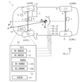
- FIG. 1 is a diagram illustrating the configuration of a vehicle to which a control device according to an embodiment is applied.
- FIG. 2 is a diagram for explaining a linear two-wheel model of a vehicle.
- FIG. 2 is a block diagram showing processing performed by the control device in FIG. 1.
- FIG. 2 is an example of a flowchart executed by the control device of FIG. 1.
- FIG. 1 is a diagram illustrating the configuration of a vehicle to which a control device according to an embodiment is applied.
- FIG. 2 is a diagram for explaining a linear two-wheel model of a vehicle.
- FIG. 2 is a block diagram showing processing performed by the control device in FIG. 1.
- FIG. 2 is an example of a flowchart executed by the control device of FIG. 1.
- a vehicle control device as an embodiment will be described with reference to the drawings.
- the embodiments shown below are merely illustrative, and there is no intention to exclude the application of various modifications and techniques not specified in the embodiments below.
- the configuration of each embodiment can be modified and implemented in various ways without departing from the spirit thereof. Further, they can be selected or combined as necessary.
- the forward direction of the vehicle is defined as the front (front of the vehicle), and left and right are defined with the front as a reference.
- the control device 10 of this embodiment is applied to the vehicle 1 illustrated in FIG. 1, and has a function of determining at least an index indicating the slipperiness of the rear wheels 2R of the vehicle 1 (rear wheel grip degree to be described later).
- the control device 10 is one of the electronic control units (ECU, Electronic Control Unit) mounted on the vehicle 1, and is expressed as "ECU" in FIG. 1.
- the control device 10 is equipped with a processor (microprocessor) such as a CPU (Central Processing Unit) or an MPU (Micro Processing Unit), a ROM (Read Only Memory), a RAM (Random Access Memory), a nonvolatile memory, and the like.
- a processor is an arithmetic processing device that includes a control unit (control circuit), an arithmetic unit (arithmetic circuit), a cache memory (register group), etc. Further, ROM, RAM, and nonvolatile memory are memory devices in which programs and data being worked on are stored. The contents of the judgments and controls performed by the control device 10 are recorded and stored in memory as firmware or application programs, and when the program is executed, the contents of the program are developed in the memory space and executed by the processor.
- the vehicle 1 is an engine car, an electric vehicle (EV), an electric vehicle (HEV), a plug-in hybrid electric vehicle (PHEV), or a fuel cell vehicle (FCV), which is equipped with a drive source 3 such as an engine or an electric motor, for example. Fuel Cell Vehicle).
- a brake device 4 is provided on the left and right front wheels 2FL, 2FR and the left and right rear wheels 2RL, 2RR of the vehicle 1, and each of the four wheels is brake-controlled independently.
- the vehicle 1 also includes a power steering device 5 that assists the driver's steering operation, and an AFS 6 (Active Front Steering) that can actively control the steering amount (front wheel steering angle) of the front wheels 2F (2FL, 2FR).
- AFS 6 Active Front Steering
- ARS7 Active Rear Steering
- the vehicle 1 of this embodiment is provided with an active suspension 8 and a notification device 9 that makes an announcement to the driver via display or voice.
- These devices 3 to 9 are individually controlled by an on-vehicle control device (not shown).
- a control device engine ECU or motor ECU
- the vehicle 1 is equipped with an ECU and an ECU that controls the notification device 9.
- the control device 10 controls the devices 3 to 9, it sends commands to these various ECUs, and the various ECUs control the corresponding devices 3 to 9.
- the devices 3 to 8 that play the role of converting energy into mechanical displacement or stress can be called "actuators.”
- a common ECU may have a function of controlling a plurality of devices 3 to 9.
- the vehicle 1 is provided with a sensor for acquiring various information about the vehicle 1.
- a vehicle speed sensor 21, a yaw rate sensor 22, a lateral acceleration sensor 23, and a longitudinal acceleration sensor 24 are provided, and each of the sensors 21 to 24 is connected to the control device 10.
- the vehicle speed sensor 21 (vehicle speed detection means) is a sensor that detects the vehicle body speed V of the vehicle 1
- the yaw rate sensor 22 (yaw rate detection means) detects the rotational angular velocity around the vertical axis passing through the center of gravity G of the vehicle 1 as a yaw rate r.
- This is a sensor that detects as follows.
- the positive direction of the vehicle body speed V is the direction from the center of gravity G to the front
- the yaw rate r is the direction from the center of gravity G when the vehicle 1 is viewed from above. Counterclockwise is considered the positive direction.
- the lateral acceleration sensor 23 (lateral acceleration detection means) and the longitudinal acceleration sensor 24 (longitudinal acceleration detection means) are sensors that respectively detect lateral acceleration A y and longitudinal acceleration A x at the center of gravity G of the vehicle 1.
- the positive direction of the lateral acceleration A y is to the left from the center of gravity G
- the positive direction of the longitudinal acceleration A x is toward the front from the center of gravity G. It is said that Information detected by each sensor 21 to 24 is sent to the control device 10.
- the means for detecting the vehicle speed V is not limited to the vehicle speed sensor 21; for example, a wheel speed sensor that detects the angular velocity of each wheel 2 may be provided, and the vehicle speed V may be calculated from the detected value of the wheel speed sensor.
- the means for detecting the yaw rate r, the means for detecting the lateral acceleration Ay , and the means for detecting the longitudinal acceleration Ax are not limited to the yaw rate sensor 22, the lateral acceleration sensor 23, and the longitudinal acceleration sensor 24.
- the lateral acceleration A y can be estimated based on the steering angle and the vehicle speed V, or the estimated value or the value detected by the lateral acceleration sensor 23 can be corrected based on another sensor value . may be detected.
- the yaw rate r and the longitudinal acceleration A x may be detected by correcting the values detected by the yaw rate sensor 22 and the longitudinal acceleration sensor 24 based on other sensor values.
- the estimation section and the correction section (functional elements of the control device) can serve as each detection means.
- the control device 10 of the present embodiment uses the information detected by the various sensors 21 to 24 to estimate the "rear wheel grip degree k rg " which is an index indicating the slipperiness of the rear wheels 2R of the vehicle 1, The actuator or notification device 9 is controlled accordingly.
- the control device 10 may also have a function of determining the road surface condition while the vehicle 1 is traveling based on the rear wheel grip degree k rg . Examples of the road surface conditions determined here include dry paved roads, wet roads, snowy roads, frozen roads, gravel (unpaved roads), muddy roads, and the like.
- the rear wheel grip degree k rg is a value that represents the degree of slipperiness (frictional force, rear wheel cornering power) of the rear wheel 2R of the vehicle 1.
- the control device 10 includes a first estimation section 11, a second estimation section 12, and a control section 13 as functional elements for estimating the rear wheel grip degree k rg and controlling the actuator or the notification device 9 of the vehicle 1. Be prepared. Furthermore, the control device 10 of the present embodiment includes a determination unit 14 as a functional element for determining the road surface condition from the estimated rear wheel grip degree k rg . These elements are shown by classifying the functions of the control device 10 for convenience. Each of these elements can be written as an independent program, and can also be written as a composite program that combines a plurality of elements. A program corresponding to each element is stored in the memory or storage device of the control device 10 and executed by the processor.
- the first estimating unit 11 specifies a coefficient that includes the rear wheel cornering power K r of the vehicle 1 among the coefficients included in the transfer function G(s) of the product of the vehicle body speed V and the yaw rate r using the lateral acceleration A y as input. This is to estimate the coefficients.
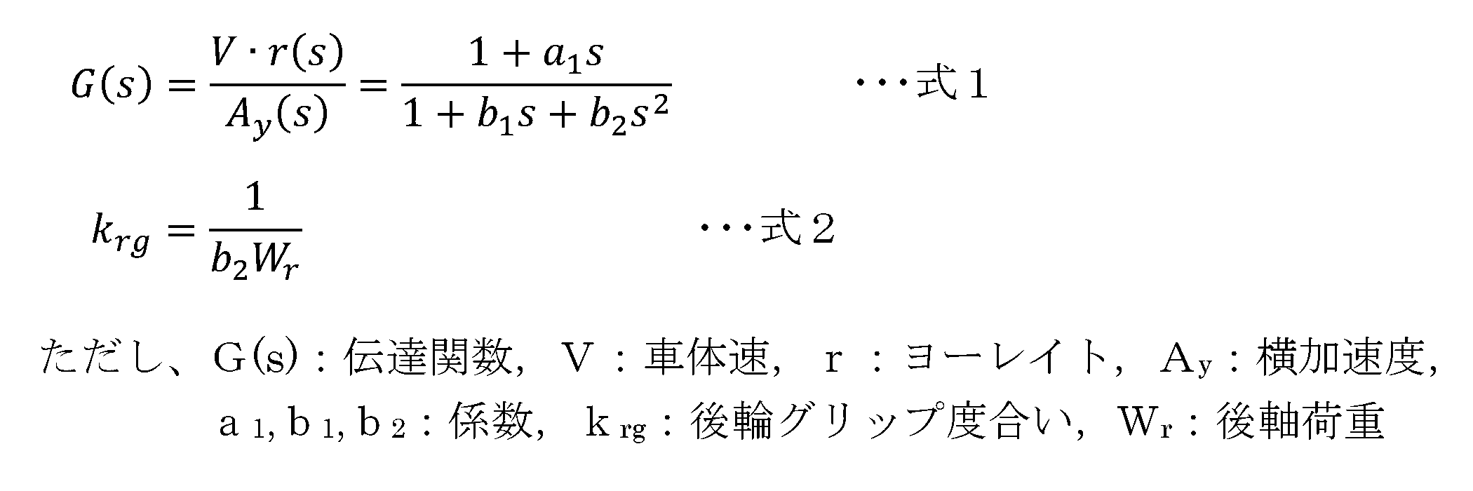
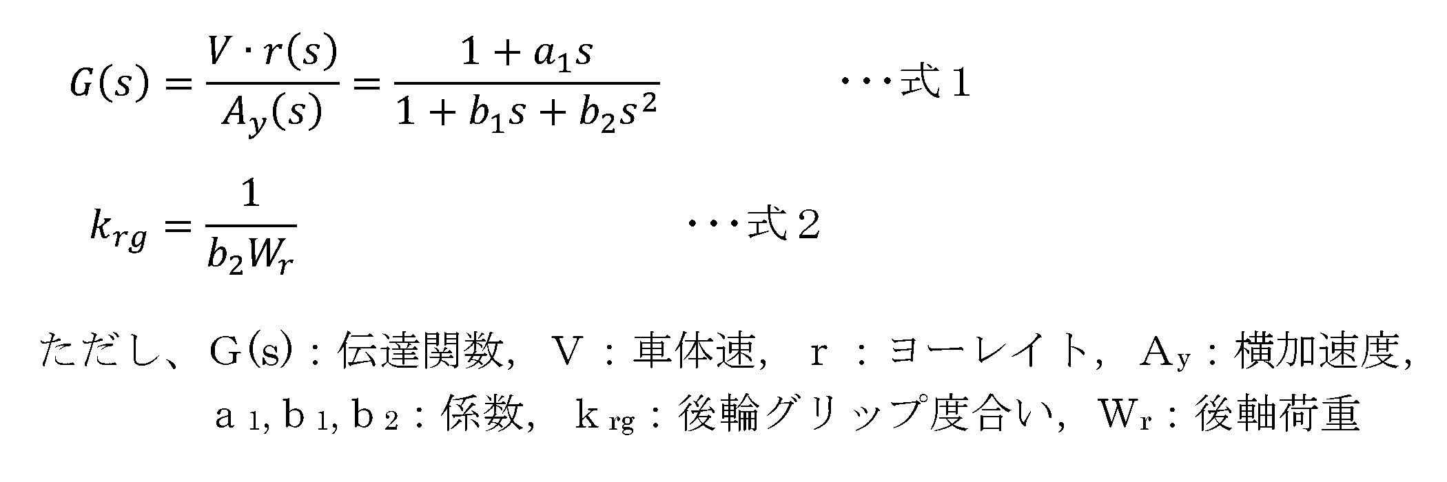
- the transfer function G(s) is expressed by Equation 1 below. Note that a 1 , b 1 , and b 2 in Equation 1 are coefficients. In this way, the transfer function G(s) has a linear numerator and a quadratic denominator, with a steady gain of 1.
- the vehicle 1 is modeled using a linear two-wheel model.
- the linear two-wheel model is a mathematical model of the vehicle 1 that is linearized by considering the vehicle 1 as one rigid body and reducing the degree of freedom of movement.
- the vehicle 1 is regarded as a rigid body having one front wheel 2F and one rear wheel 2R, and only plane motion in the lateral direction and yaw direction when the vehicle speed is constant is considered. Further, it is assumed that the cornering force generated by the wheels 2 is proportional to the sideslip angle.
- Equation 2 The equation of motion in this two-wheel model is expressed by Equation 2 below.
- m is the vehicle mass
- ⁇ is the slip angle at the center of gravity
- I is the yaw moment of inertia
- K f is the front wheel cornering power
- ⁇ f is the front wheel slip angle (lateral slip angle of the front wheel 2F)
- ⁇ r is the rear wheel slip angle (the side slip angle of the front wheel 2F).
- L f is the distance in the longitudinal direction between the front axle and the center of gravity G
- L r is the distance in the longitudinal direction between the rear axle and the center of gravity G.
- Equation 3 assuming that the vehicle speed V is constant, the above equation 2 becomes linear with respect to the center of gravity slip angle ⁇ and the yaw rate r. Based on this assumption, when Equation 2 is rearranged by Laplace transform, the following Equation 4 is obtained. Note that L is the wheelbase (distance between the front and rear axles).
- the coefficients a 1 and b 2 include the rear wheel cornering power K r . Furthermore, since m, L f , I, and L included in these coefficients a 1 and b 2 are predetermined vehicle specification values, changes in coefficients a 1 and b 2 are caused by rear wheel cornering power K. This occurs due to changes in r . Therefore, the first estimation unit 11 uses at least one of the coefficients a 1 and b 2 as a specific coefficient, and estimates the value of the specific coefficient by using a predetermined estimation method. Thereby, the first estimation unit 11 can indirectly estimate the change in the rear wheel cornering power K r .
- the first estimation unit 11 of this embodiment estimates the denominator quadratic coefficient b 2 as a specific coefficient.
- the predetermined estimation method include an estimation method using a Kalman filter and an iterative least squares method.
- the detection means sensors 21 to 24
- the deviation between the detected value (output measurement value) and the estimated output value estimated by applying the estimated state quantity before the one-time step to the mathematical model stored in the electronic control unit is multiplied by a predetermined gain.
- the current state quantity estimated value (specific coefficient b 2 ) is estimated.
- the first estimation unit 11 of this embodiment estimates the coefficient b 2 as a specific coefficient, but may also estimate the coefficient a 1 as a specific coefficient, or may estimate these two coefficients a 1 and b 2 as a specific coefficient. Alternatively, the weighted average of these two estimated values a 1 and b 2 may be taken.
- the second estimation unit 12 estimates the rear wheel grip degree k rg based on at least the specific coefficient estimated by the first estimation unit 11 and the longitudinal acceleration A x detected by the longitudinal acceleration sensor 24. It is.
- the second estimator 12 of this embodiment calculates the rear wheel grip degree k rg based on the specific coefficient b 2 estimated by the first estimator 11, as shown in FIG. 3 and Equations 5 and 6 below. It is determined as the reciprocal of the product of the acceleration A x and the rear axle load W r .
- the rear axle load W r is a value obtained by adding the load movement amount ⁇ W x of the front and rear axles to the stationary rear axle load W r0 (fixed value) when the vehicle 1 is stationary.
- the longitudinal acceleration A x is used in calculating the load movement amount ⁇ W x of the longitudinal axis.
- h cg is the height of the center of gravity (fixed value).
- the second estimation unit 12 of this embodiment calculates the rear axle load W r from the detected longitudinal acceleration A x and the vehicle specification value, and calculates the specific coefficient b 2 estimated by the first estimation unit 11.
- the rear wheel grip degree k rg is estimated (calculated) from the rear axle load W r .
- the second estimation section 12 sends the estimated rear wheel grip degree k rg to the control section 13 .
- the control unit 13 controls the actuator or the notification device 9 of the vehicle 1 according to the rear wheel grip degree k rg estimated by the second estimation unit 12 .
- the actuator controlled here is at least one of the drive source 3, brake device 4, power steering device 5, AFS 6, ARS 7, and active suspension 8, or all of them.
- the control unit 13 controls the vehicle 1 because the smaller the rear wheel grip degree k rg (that is, the more likely the rear wheel 2R is to slip), the more likely the vehicle 1 is to spin (or the more likely it is to occur). Control the actuator to stabilize its behavior.
- the control unit 13 compares the rear wheel grip degree k rg with a preset first threshold value, and controls the actuator to stabilize the behavior of the vehicle 1 when the rear wheel grip degree k rg is less than the first threshold value. may be controlled.
- the control unit 13 controls the required torque required for the vehicle 1 and the driver's control.
- the actuator is controlled according to pedal operation, vehicle speed V, etc. Control at this time is called normal control.
- the normal control may be performed by the control device 10 or by another vehicle-mounted control device.
- the control unit 13 can determine whether or not to perform the normal control, for example, based on whether the rear wheel grip degree k rg exceeds a preset second threshold value.
- the second threshold is a larger value than the first threshold.
- the control unit 13 of this embodiment includes a first control unit 13A that adjusts the control amount of at least one of the driving force and braking force of the vehicle 1 according to the rear wheel grip degree k rg .
- the first control unit 13A sends a command to the control device of the driving source 3 to control the output (driving force) of the driving source 3.
- the driving force may be adjusted by controlling the power transmission device.
- the first control unit 13A sends a command to the control device of the brake device 4 to control the output (braking force) of the brake device 4. Since the brake device 4 can control each wheel 2 individually, more detailed adjustment is possible. Note that it is also possible to adjust the control amount of the braking force by controlling the drive source 3.
- the first control unit 13A of this embodiment adjusts the control amount so as not to impede its implementation.
- the first control unit 13A adjusts the control amount so as to limit the torque movement in the front, rear, left, and right directions, so that the rear wheel 2R is more likely to slip, depending on the rear wheel grip degree k rg . do. That is, in this case, the first control unit 13A adjusts the control amount of at least one of the driving force and the braking force so as to limit the torque movement with respect to the driving force and the braking force under normal control.
- 13 A of 1st control parts may switch a control map, and may increase or suppress the control output calculated by normal control.
- the control unit 13 of the present embodiment has a second control unit that adjusts the steering assist torque of the vehicle 1, the amount of steering of each wheel 2, and the control amount of at least one of the active suspensions 8 according to the rear wheel grip degree krg . It includes a control section 13B.
- the second control section 13B sends a command to the control device of the power steering device 5 to control the output (steering assist torque) of the power steering device 5.
- the second control unit 13B sends a command to the control devices of the AFS 6 and ARS 7, and controls the outputs (front wheel steering angle, rear wheel steering angle) of the AFS 6 and ARS 7.
- the second control unit 13B sends a command to the control device of the active suspension 8, and controls energy sources such as oil pressure, pneumatic pressure, and an electric motor.
- the steering assist torque of the vehicle 1, the amount of steering of each wheel 2, and the active suspension 8 are all the same as the driving force and braking force during normal driving without side slipping of the rear wheels 2R (that is, during normal control). It is controlled according to the steering operation by the driver, the vehicle speed V, etc.
- the second control unit 13B of this embodiment does not inhibit normal control when it is performed.
- the second control unit 13B controls, depending on the rear wheel grip degree k rg , the more easily the rear wheel 2R slips, the more maneuverability is ensured while suppressing the side slip of the rear wheel 2R.
- the control amount of at least one of the steering assist torque, the steering amount, and the active suspension 8 is adjusted so that the steering assist torque, the steering amount, and the active suspension 8 are controlled.
- the second control part 13B may switch a control map, and may increase or suppress the control output calculated by normal control.
- the combination of control by the first control unit 13A and control by the second control unit 13B is arbitrary.
- a configuration may be adopted in which both the driving force and the braking force are controlled by the first control section 13A, and the steering assist torque, the steering amount, and the active suspension 8 are all controlled by the second control section 13B.
- a configuration may be adopted in which only the braking force is controlled by the first control section 13A, and only the steering assist torque is controlled by the second control section 13B.
- a configuration may be adopted in which both the driving force and the braking force are controlled by the first control section 13A, and the control by the second control section 13B is not performed. In this way, by using two or more types of control in combination, the degree of freedom in control increases and more precise vehicle motion control becomes possible.
- the control unit 13 controls the notification device 9 to inform the driver of the skidding state of the vehicle 1. You may make an announcement.
- the third threshold is a value smaller than the second threshold, and may be the same as or different from the first threshold.
- the determining unit 14 determines the road surface condition on which the vehicle 1 is traveling based on the rear wheel grip degree k rg estimated by the second estimating unit 12 . In this determination, for example, a previously stored correspondence relationship between the rear wheel grip degree k rg and the road surface condition can be used. As an example, the determining unit 14 determines that the road is a dry paved road when the rear wheel grip degree k rg is equal to or greater than the first predetermined value, and the rear wheel grip degree k rg is less than the first predetermined value, and If the road is equal to or greater than a second predetermined value smaller than the first predetermined value, it is determined that the road is wet.
- the determination unit 14 determines that the road is covered with snow when the rear wheel grip degree k rg is less than the second predetermined value and is equal to or greater than a third predetermined value smaller than the second predetermined value. Further, the determination unit 14 determines that the road surface is frozen when the rear wheel grip degree k rg is less than a third predetermined value. Similar determinations may be made for other road conditions (unpaved roads, muddy roads, etc.).
- control unit 13 may control the notification device 9 in accordance with the rear wheel grip degree k rg estimated by the second estimating unit 12 instead of or in addition to controlling the actuator described above.
- control unit 13 may announce the result of the determination of the road surface condition by the determination unit 14 to the driver by voice or display.
- FIG. 4 shows an example of a flowchart executed in the control device 10 described above. This flowchart is executed at a predetermined calculation cycle, for example, when the main power source of the vehicle 1 is on.
- step S1 information on various sensors 21 to 24 is acquired.
- step S2 the first estimating unit 11 estimates the specific coefficient b 2 included in the transfer function G(s) of Equation 1 above.
- step S3 the second estimation unit 12 calculates the rear axle load W r (step S3) and estimates (calculates) the rear wheel grip degree k rg (step S4).
- the actuator or notification device 9 is controlled by the control section 13 (first control section 13A, second control section 13B) according to the rear wheel grip degree k rg , and this flowchart is returned.
- the rear wheel grip degree k rg based on the specific coefficients a 1 and b 2 including the rear wheel cornering power K r indicates the slipperiness of the rear wheel 2R, and is a parameter that can express the friction state between the rear wheel 2R and the road surface. .
- the above-described control device 10 focuses on the fact that the change in the rear wheel cornering power K r can be determined from the change in the specific coefficients a 1 and b 2 included in the transfer function G(s) . 2 is estimated using three detected values (lateral acceleration A y , yaw rate r, and vehicle speed V).
- the rear wheel grip degree k rg is estimated based on the specific coefficients a 1 and b 2 and the longitudinal acceleration A x .
- the present control device 10 compared to the conventional method of calculating the rear wheel cornering power K r from the transfer function G(s), it is possible to reduce the uncertainty due to fewer calculation processes, and improve the estimation. Accuracy can be increased.
- the information on the longitudinal acceleration A x is taken into consideration, it is possible to estimate the rear wheel grip degree k rg according to the driving condition, and from this point as well, the estimation accuracy can be improved.
- control device 10 controls the actuator or notification device 9 of the vehicle 1 according to the rear wheel grip degree k rg based on the specific coefficients a 1 , b 2 and the longitudinal acceleration A x .
- Controllability can be improved. This can contribute to improving, for example, suppression control of spin behavior, which is one type of vehicle motion control.
- the control amount of at least one of the driving force and braking force of the vehicle 1 is adjusted according to the rear wheel grip degree k rg .
- the control amount of at least one of the driving force and braking force is adjusted by increasing or decreasing according to the slipperiness (size of frictional force) of the rear wheel 2R (for example, when the rear wheel 2R is slippery, the torque movement in the front, rear, left, and right directions is adjusted). Therefore, it is possible to contribute to improving the suppression control of spin behavior, and for example, it is possible to realize a desired behavior.
- the control amount of at least one of the steering assist torque of the vehicle 1, the amount of turning of each wheel 2, and the active suspension 8 is adjusted according to the rear wheel grip degree k rg . Therefore, maneuverability can be ensured by increasing or decreasing the control amount of the steering assist torque and the steering amount in accordance with the slipperiness (size of frictional force) of the rear wheels 2R. Furthermore, the grounding state of the wheels 2 can also be controlled by adjusting the control amount (hydraulic pressure or air pressure) of the active suspension 8. These can contribute to improving the suppression control of spin behavior, and for example, can realize a desired behavior.
- the rear wheel grip degree k rg is estimated using the above equations 5 and 6, so it is possible to estimate the rear wheel grip degree k rg according to the driving condition by simple calculation. can.
- the denominator quadratic coefficient b 2 of the above equations 1 and 4 is used as the specific coefficient. This is because the inventors have found that, in estimation using a Kalman filter, for example, the coefficient b 2 yields a value closer to the true state. Therefore, by using this coefficient b 2 as a specific coefficient, the accuracy of estimating the rear wheel grip degree k rg can be further improved.
- control device 10 The configuration of the control device 10 described above is an example, and is not limited to the configuration described above.
- the control unit 13 is provided with two functions, the first control unit 13A and the second control unit 13B, but these functions do not need to be separated.
- the above six control targets (driving force, braking force, steering assist torque, steering amount, active suspension 8, and notification device 9) may be controlled independently, or may be used together or in combination. good.
- the determination unit 14 determines the road surface condition, but this determination may be omitted. Furthermore, the method for determining the rear axle load W r is not limited to the above method. In the embodiment described above, the second-order denominator coefficient b 2 is estimated as the specific coefficient, but the first-order denominator coefficient a 1 may be estimated as the specific coefficient. Note that the method for estimating the rear wheel grip degree k rg is not limited to the above method, and may be based on at least the specific coefficient and the longitudinal acceleration A x .
- the configuration of the vehicle 1 to which the control device 10 is applied is also one example, and is not limited to the above-mentioned configuration.
- the ASC active stability control
- the ASC may be activated in accordance with the rear wheel grip degree k rg estimated by the control device 10 described above.
- the AFS 6 and ARS 7 may be omitted from the vehicle 1 described above, or a drive source 3 (for example, an in-wheel motor) may be provided for each wheel 2.
Landscapes
- Engineering & Computer Science (AREA)
- Transportation (AREA)
- Mechanical Engineering (AREA)
- Chemical & Material Sciences (AREA)
- Combustion & Propulsion (AREA)
- Automation & Control Theory (AREA)
- Human Computer Interaction (AREA)
- Physics & Mathematics (AREA)
- Mathematical Physics (AREA)
- Control Of Driving Devices And Active Controlling Of Vehicle (AREA)
Abstract
Description
開示の車両の制御装置は、車両の車体速を検出する車体速検出手段と、前記車両のヨーレイトを検出するヨーレイト検出手段と、前記車両の横加速度を検出する横加速度検出手段と、前記車両の前後加速度を検出する前後加速度検出手段とが設けられた前記車両に適用される。前記制御装置は、前記横加速度を入力とした前記車体速及び前記ヨーレイトの積の伝達関数に含まれる係数のうち、前記車両の後輪コーナリングパワーが含まれる特定係数を推定する第一推定部と、少なくとも前記特定係数及び前記前後加速度に基づいて、後輪のすべりやすさを示す後輪グリップ度合いを推定する第二推定部と、前記後輪グリップ度合いに応じて前記車両のアクチュエータ又は報知装置を制御する制御部と、を備える。
本実施形態の制御装置10は、図1に例示する車両1に適用され、少なくとも車両1の後輪2Rのすべりやすさを示す指標(後述する後輪グリップ度合い)を判定する機能を持つ。制御装置10は、車両1に搭載される電子制御装置(ECU,Electronic Control Unit)の一つであり、図1では「ECU」と表現している。制御装置10には、例えばCPU(Central Processing Unit),MPU(Micro Processing Unit)等のプロセッサ(マイクロプロセッサ)やROM(Read Only Memory),RAM(Random Access Memory),不揮発メモリ等が実装される。
本実施形態の制御装置10は、各種センサ21~24で検出された情報を用いて、車両1の後輪2Rのすべりやすさを示す指標である「後輪グリップ度合いkrg」を推定し、これに応じてアクチュエータ又は報知装置9を制御する。なお、制御装置10は、後輪グリップ度合いkrgに基づいて、車両1の走行中の路面状況を判定する機能を併せ持つものでもよい。ここで判定される路面状況としては、例えば、乾燥舗装路,ウェット路,積雪路,凍結路面,グラベル(未舗装路),泥濘路などが挙げられる。





一方、通常制御が実施されない場合には、第一制御部13Aは、後輪グリップ度合いkrgに応じて、後輪2Rがすべりやすいほど、前後左右のトルク移動を制限するよう、制御量を調整する。つまりこの場合、第一制御部13Aは、通常制御での駆動力及び制動力に対し、トルク移動を制限するように、駆動力及び制動力の少なくとも一方の制御量を調整する。なお、当該調整において、第一制御部13Aは、制御マップを切り替えてもよいし、通常制御で算出される制御出力を増加させたり抑制したりしてもよい。
図4に、上述した制御装置10において実施されるフローチャート例を示す。このフローチャートは、例えば、車両1の主電源がオンの場合に所定の演算周期で実施される。まず、ステップS1において、各種センサ21~24の情報が取得される。ステップS2では、第一推定部11により、上記の式1の伝達関数G(s)に含まれる特定係数b2が推定される。次いで、第二推定部12により、後軸荷重Wrが算出されるとともに(ステップS3)、後輪グリップ度合いkrgが推定(算出)される(ステップS4)。ステップS5では、制御部13(第一制御部13A,第二制御部13B)により、後輪グリップ度合いkrgに応じてアクチュエータ又は報知装置9が制御され、このフローチャートをリターンする。
後輪コーナリングパワーKrを含む特定係数a1,b2に基づく後輪グリップ度合いkrgは、後輪2Rのすべりやすさを示し、後輪2Rと路面間の摩擦状態を表現できるパラメータである。上述した制御装置10では、伝達関数G(s)に含まれる特定係数a1,b2の変化から後輪コーナリングパワーKrの変化を知ることができる点に着目し、特定係数a1,b2を、三つの検出値(横加速度Ay,ヨーレイトr,車体速V)を用いて推定する。さらに、この特定係数a1,b2と前後加速度Axとに基づき後輪グリップ度合いkrgを推定する。このように、本制御装置10であれば、伝達関数G(s)から後輪コーナリングパワーKrを算出する従来手法と比較して、計算過程が少ない分、不確かさを減らすことができ、推定精度を高めることができる。また、前後加速度Axの情報が加味されるため、走行状態に応じた後輪グリップ度合いkrgを推定することができ、この点からも推定精度を高められる。
また、上述した制御装置10では、特定係数として、上記の式1及び式4の分母二次の係数b2を用いる。これは、例えばカルマンフィルタを用いた推定において、係数b2の方が真の状態に近い値が出ることが発明者らにより判明したからである。したがって、この係数b2を特定係数として用いることで、後輪グリップ度合いkrg推定精度をより高めることができる。
上述した制御装置10の構成は一例であって、上述したものに限られない。例えば、上記の制御装置10には、制御部13に、第一制御部13A及び第二制御部13Bの二つの機能が設けられているが、これらの機能を分けなくてもよい。また、上記の六つの制御対象(駆動力,制動力,操舵アシストトルク,転舵量,アクティブサスペンション8,報知装置9)は、単独で制御してもよいし、併用したり組合せたりしてもよい。
上記実施形態では、特定係数として、分母二次の係数b2を推定したが、分母一次の係数a1を特定係数として推定してもよい。なお、後輪グリップ度合いkrgの推定手法は上記のものに限られず、少なくとも特定係数と前後加速度Axとに基づいていればよい。
2 車輪
2FL 左前輪(前輪,車輪)
2FR 右前輪(前輪,車輪)
2RL 左後輪(後輪,車輪)
2RR 右後輪(後輪,車輪)
3 駆動源(アクチュエータ)
4 ブレーキ装置(アクチュエータ)
5 パワーステアリング装置(アクチュエータ)
6 AFS(アクチュエータ)
7 ARS(アクチュエータ)
8 アクティブサスペンション(アクチュエータ)
9 報知装置
10 制御装置
11 第一推定部
12 第二推定部
13 制御部
13A 第一制御部
13B 第二制御部
14 判定部
21 車速センサ(車体速検出手段)
22 ヨーレイトセンサ(ヨーレイト検出手段)
23 横加速度センサ(横加速度検出手段)
24 前後加速度センサ(前後加速度検出手段)
Ax 前後加速度
Ay 横加速度
a1 係数(特定係数)
b1 係数
b2 係数(特定係数)
G 重心
G(s) 伝達関数
I ヨー慣性モーメント
krg 後輪グリップ度合い
Kr 後輪コーナリングパワー
L ホイールベース(前後車軸の距離)
Lf 前車軸と重心Gとの前後方向の距離
Lr 後車軸と重心Gとの前後方向の距離
m 車両質量
r ヨーレイト
V 車体速
Wr 後軸荷重
Wr0 静止後軸荷重
β 重心スリップ角
βf 前輪スリップ角
βr 後輪スリップ角
δ 操舵角
Claims (9)
- 車両の車体速を検出する車体速検出手段と、前記車両のヨーレイトを検出するヨーレイト検出手段と、前記車両の横加速度を検出する横加速度検出手段と、前記車両の前後加速度を検出する前後加速度検出手段とが設けられた前記車両の制御装置であって、
前記横加速度を入力とした前記車体速及び前記ヨーレイトの積の伝達関数に含まれる係数のうち、前記車両の後輪コーナリングパワーが含まれる特定係数を推定する第一推定部と、
少なくとも前記特定係数及び前記前後加速度に基づいて、後輪のすべりやすさを示す後輪グリップ度合いを推定する第二推定部と、
前記後輪グリップ度合いに応じて前記車両のアクチュエータ又は報知装置を制御する制御部と、を備えた
ことを特徴とする、車両の制御装置。 - 前記制御部には、前記後輪グリップ度合いに応じて前記車両の駆動力及び制動力の少なくとも一方の制御量を調整する第一制御部が含まれる
ことを特徴とする、請求項1記載の車両の制御装置。 - 前記制御部には、前記後輪グリップ度合いに応じて、前記車両の操舵アシストトルク及び各車輪の転舵量並びにアクティブサスペンションの少なくとも何れか一つの制御量を調整する第二制御部が含まれる
ことを特徴とする、請求項1又は2記載の車両の制御装置。 - 前記第二推定部は、前記車両の静止状態での静止後軸荷重と前記前後加速度とに基づいて前記車両の後軸荷重を求め、前記特定係数及び前記後軸荷重の積の逆数を前記後輪グリップ度合いとして求める
ことを特徴とする、請求項1又は2記載の車両の制御装置。 - 前記第二推定部は、前記車両の静止状態での静止後軸荷重と前記前後加速度とに基づいて前記車両の後軸荷重を求め、前記特定係数及び前記後軸荷重の積の逆数を前記後輪グリップ度合いとして求める
ことを特徴とする、請求項3記載の車両の制御装置。 - 前記第一推定部は、下記の式1で表現される前記伝達関数の分母二次の係数b2を前記特定係数として推定し、
前記第二推定部は、下記の式2により前記後輪グリップ度合いを推定する
ことを特徴とする、請求項1又は2記載の車両の制御装置。

- 前記第一推定部は、下記の式1で表現される前記伝達関数の分母二次の係数b2を前記特定係数として推定し、
前記第二推定部は、下記の式2により前記後輪グリップ度合いを推定する
ことを特徴とする、請求項3記載の車両の制御装置。

- 前記第一推定部は、下記の式1で表現される前記伝達関数の分母二次の係数b2を前記特定係数として推定し、
前記第二推定部は、下記の式2により前記後輪グリップ度合いを推定する
ことを特徴とする、請求項4記載の車両の制御装置。
- 前記第一推定部は、下記の式1で表現される前記伝達関数の分母二次の係数b2を前記特定係数として推定し、
前記第二推定部は、下記の式2により前記後輪グリップ度合いを推定する
ことを特徴とする、請求項5記載の車両の制御装置。
Priority Applications (2)
| Application Number | Priority Date | Filing Date | Title |
|---|---|---|---|
| JP2024517285A JP7764953B2 (ja) | 2022-04-28 | 2023-04-21 | 車両の制御装置 |
| US18/849,839 US20250222933A1 (en) | 2022-04-28 | 2023-04-21 | Control device for vehicle |
Applications Claiming Priority (2)
| Application Number | Priority Date | Filing Date | Title |
|---|---|---|---|
| JP2022074224 | 2022-04-28 | ||
| JP2022-074224 | 2022-04-28 |
Publications (1)
| Publication Number | Publication Date |
|---|---|
| WO2023210534A1 true WO2023210534A1 (ja) | 2023-11-02 |
Family
ID=88518832
Family Applications (1)
| Application Number | Title | Priority Date | Filing Date |
|---|---|---|---|
| PCT/JP2023/015964 Ceased WO2023210534A1 (ja) | 2022-04-28 | 2023-04-21 | 車両の制御装置 |
Country Status (3)
| Country | Link |
|---|---|
| US (1) | US20250222933A1 (ja) |
| JP (1) | JP7764953B2 (ja) |
| WO (1) | WO2023210534A1 (ja) |
Citations (6)
| Publication number | Priority date | Publication date | Assignee | Title |
|---|---|---|---|---|
| JP2003312465A (ja) * | 2002-04-23 | 2003-11-06 | Aisin Seiki Co Ltd | 車輪のグリップ度推定装置、及び該装置を備えた車両の運動制御装置 |
| JP2004074842A (ja) * | 2002-08-12 | 2004-03-11 | Toyota Central Res & Dev Lab Inc | 路面摩擦状態推定装置 |
| JP2004352046A (ja) * | 2003-05-28 | 2004-12-16 | Toyota Central Res & Dev Lab Inc | タイヤグリップ度推定装置及び方法、走行状態制御方法 |
| JP2005008062A (ja) * | 2003-06-19 | 2005-01-13 | Toyota Central Res & Dev Lab Inc | タイヤグリップ度推定装置 |
| JP2008024233A (ja) * | 2006-07-24 | 2008-02-07 | Hitachi Ltd | 車両横すべり角演算装置 |
| JP2010202046A (ja) * | 2009-03-03 | 2010-09-16 | Nissan Motor Co Ltd | 車両状態推定装置 |
Family Cites Families (1)
| Publication number | Priority date | Publication date | Assignee | Title |
|---|---|---|---|---|
| GB2565346B (en) * | 2017-08-11 | 2020-02-26 | Jaguar Land Rover Ltd | Control system for a steer-by-wire steering system |
-
2023
- 2023-04-21 US US18/849,839 patent/US20250222933A1/en active Pending
- 2023-04-21 WO PCT/JP2023/015964 patent/WO2023210534A1/ja not_active Ceased
- 2023-04-21 JP JP2024517285A patent/JP7764953B2/ja active Active
Patent Citations (6)
| Publication number | Priority date | Publication date | Assignee | Title |
|---|---|---|---|---|
| JP2003312465A (ja) * | 2002-04-23 | 2003-11-06 | Aisin Seiki Co Ltd | 車輪のグリップ度推定装置、及び該装置を備えた車両の運動制御装置 |
| JP2004074842A (ja) * | 2002-08-12 | 2004-03-11 | Toyota Central Res & Dev Lab Inc | 路面摩擦状態推定装置 |
| JP2004352046A (ja) * | 2003-05-28 | 2004-12-16 | Toyota Central Res & Dev Lab Inc | タイヤグリップ度推定装置及び方法、走行状態制御方法 |
| JP2005008062A (ja) * | 2003-06-19 | 2005-01-13 | Toyota Central Res & Dev Lab Inc | タイヤグリップ度推定装置 |
| JP2008024233A (ja) * | 2006-07-24 | 2008-02-07 | Hitachi Ltd | 車両横すべり角演算装置 |
| JP2010202046A (ja) * | 2009-03-03 | 2010-09-16 | Nissan Motor Co Ltd | 車両状態推定装置 |
Also Published As
| Publication number | Publication date |
|---|---|
| US20250222933A1 (en) | 2025-07-10 |
| JPWO2023210534A1 (ja) | 2023-11-02 |
| JP7764953B2 (ja) | 2025-11-06 |
Similar Documents
| Publication | Publication Date | Title |
|---|---|---|
| US8244432B2 (en) | Road-surface friction-coefficient estimating device | |
| JP6377162B2 (ja) | ビークル制御システムと方法 | |
| CN104417564B (zh) | 车辆行为控制装置 | |
| CN111483467B (zh) | 一种车辆控制方法及装置 | |
| JP2004130965A (ja) | 路面状態推定装置、及び該装置を備えた車両の運動制御装置 | |
| JP2004130964A (ja) | 路面状態推定装置、及び該装置を備えた車両の運動制御装置 | |
| JP2002145037A (ja) | 車両の路面摩擦係数推定装置 | |
| JP2002087310A (ja) | 横方向力の測定に基づいた車両軌道へのアクション | |
| CN116061934B (zh) | 用于管理底盘和传动系致动器的架构和基于模型预测控制的方法 | |
| AU2016201638A1 (en) | Vibration control device and vibration control system | |
| JP5211995B2 (ja) | 車両用減速制御装置及びその方法 | |
| US8340881B2 (en) | Method and system for assessing vehicle movement | |
| CN116198517A (zh) | 用于e-awd和e-lsd的监督控制 | |
| US12252130B2 (en) | Method for controlling traveling of vehicle | |
| KR20080105032A (ko) | 차량 특성 결정 방법 | |
| US7617036B2 (en) | Method and system for determining the velocity of an automobile | |
| JP2003146199A (ja) | 車両状態量の推定方法 | |
| JP5180610B2 (ja) | 車両の駆動力制御装置 | |
| JP3271956B2 (ja) | 車両の路面摩擦係数推定装置 | |
| JP5154397B2 (ja) | 車両運動制御装置 | |
| JP2024518686A (ja) | 車両の車輪のスリップ限界値を決定するための方法 | |
| CN118894120A (zh) | 估计极限条件下车辆的参考速度的方法 | |
| JP7764953B2 (ja) | 車両の制御装置 | |
| KR100799488B1 (ko) | 차량의 선회주행시 제어방법 | |
| JP4358070B2 (ja) | 車体スリップ角推定方法 |
Legal Events
| Date | Code | Title | Description |
|---|---|---|---|
| 121 | Ep: the epo has been informed by wipo that ep was designated in this application |
Ref document number: 23796276 Country of ref document: EP Kind code of ref document: A1 |
|
| WWE | Wipo information: entry into national phase |
Ref document number: 2024517285 Country of ref document: JP |
|
| WWE | Wipo information: entry into national phase |
Ref document number: 18849839 Country of ref document: US |
|
| NENP | Non-entry into the national phase |
Ref country code: DE |
|
| 122 | Ep: pct application non-entry in european phase |
Ref document number: 23796276 Country of ref document: EP Kind code of ref document: A1 |
|
| WWP | Wipo information: published in national office |
Ref document number: 18849839 Country of ref document: US |