WO2023210523A1 - 車両用シートの取付構造 - Google Patents
車両用シートの取付構造 Download PDFInfo
- Publication number
- WO2023210523A1 WO2023210523A1 PCT/JP2023/015882 JP2023015882W WO2023210523A1 WO 2023210523 A1 WO2023210523 A1 WO 2023210523A1 JP 2023015882 W JP2023015882 W JP 2023015882W WO 2023210523 A1 WO2023210523 A1 WO 2023210523A1
- Authority
- WO
- WIPO (PCT)
- Prior art keywords
- seat
- battery
- battery case
- coupled
- floor
- Prior art date
- Legal status (The legal status is an assumption and is not a legal conclusion. Google has not performed a legal analysis and makes no representation as to the accuracy of the status listed.)
- Ceased
Links
Images







Classifications
-
- B—PERFORMING OPERATIONS; TRANSPORTING
- B60—VEHICLES IN GENERAL
- B60N—SEATS SPECIALLY ADAPTED FOR VEHICLES; VEHICLE PASSENGER ACCOMMODATION NOT OTHERWISE PROVIDED FOR
- B60N2/00—Seats specially adapted for vehicles; Arrangement or mounting of seats in vehicles
- B60N2/005—Arrangement or mounting of seats in vehicles, e.g. dismountable auxiliary seats
- B60N2/015—Attaching seats directly to vehicle chassis
-
- B—PERFORMING OPERATIONS; TRANSPORTING
- B60—VEHICLES IN GENERAL
- B60K—ARRANGEMENT OR MOUNTING OF PROPULSION UNITS OR OF TRANSMISSIONS IN VEHICLES; ARRANGEMENT OR MOUNTING OF PLURAL DIVERSE PRIME-MOVERS IN VEHICLES; AUXILIARY DRIVES FOR VEHICLES; INSTRUMENTATION OR DASHBOARDS FOR VEHICLES; ARRANGEMENTS IN CONNECTION WITH COOLING, AIR INTAKE, GAS EXHAUST OR FUEL SUPPLY OF PROPULSION UNITS IN VEHICLES
- B60K1/00—Arrangement or mounting of electrical propulsion units
- B60K1/04—Arrangement or mounting of electrical propulsion units of the electric storage means for propulsion
-
- B—PERFORMING OPERATIONS; TRANSPORTING
- B60—VEHICLES IN GENERAL
- B60N—SEATS SPECIALLY ADAPTED FOR VEHICLES; VEHICLE PASSENGER ACCOMMODATION NOT OTHERWISE PROVIDED FOR
- B60N2/00—Seats specially adapted for vehicles; Arrangement or mounting of seats in vehicles
- B60N2/02—Seats specially adapted for vehicles; Arrangement or mounting of seats in vehicles the seat or part thereof being movable, e.g. adjustable
- B60N2/04—Seats specially adapted for vehicles; Arrangement or mounting of seats in vehicles the seat or part thereof being movable, e.g. adjustable the whole seat being movable
- B60N2/06—Seats specially adapted for vehicles; Arrangement or mounting of seats in vehicles the seat or part thereof being movable, e.g. adjustable the whole seat being movable slidable
-
- B—PERFORMING OPERATIONS; TRANSPORTING
- B60—VEHICLES IN GENERAL
- B60N—SEATS SPECIALLY ADAPTED FOR VEHICLES; VEHICLE PASSENGER ACCOMMODATION NOT OTHERWISE PROVIDED FOR
- B60N2/00—Seats specially adapted for vehicles; Arrangement or mounting of seats in vehicles
- B60N2/02—Seats specially adapted for vehicles; Arrangement or mounting of seats in vehicles the seat or part thereof being movable, e.g. adjustable
- B60N2/04—Seats specially adapted for vehicles; Arrangement or mounting of seats in vehicles the seat or part thereof being movable, e.g. adjustable the whole seat being movable
- B60N2/14—Seats specially adapted for vehicles; Arrangement or mounting of seats in vehicles the seat or part thereof being movable, e.g. adjustable the whole seat being movable rotatable, e.g. to permit easy access
-
- B—PERFORMING OPERATIONS; TRANSPORTING
- B60—VEHICLES IN GENERAL
- B60N—SEATS SPECIALLY ADAPTED FOR VEHICLES; VEHICLE PASSENGER ACCOMMODATION NOT OTHERWISE PROVIDED FOR
- B60N2/00—Seats specially adapted for vehicles; Arrangement or mounting of seats in vehicles
- B60N2/90—Details or parts not otherwise provided for
-
- B—PERFORMING OPERATIONS; TRANSPORTING
- B60—VEHICLES IN GENERAL
- B60K—ARRANGEMENT OR MOUNTING OF PROPULSION UNITS OR OF TRANSMISSIONS IN VEHICLES; ARRANGEMENT OR MOUNTING OF PLURAL DIVERSE PRIME-MOVERS IN VEHICLES; AUXILIARY DRIVES FOR VEHICLES; INSTRUMENTATION OR DASHBOARDS FOR VEHICLES; ARRANGEMENTS IN CONNECTION WITH COOLING, AIR INTAKE, GAS EXHAUST OR FUEL SUPPLY OF PROPULSION UNITS IN VEHICLES
- B60K1/00—Arrangement or mounting of electrical propulsion units
- B60K1/04—Arrangement or mounting of electrical propulsion units of the electric storage means for propulsion
- B60K2001/0405—Arrangement or mounting of electrical propulsion units of the electric storage means for propulsion characterised by their position
Definitions
- the present invention relates to a mounting structure for a vehicle seat.
- Patent Document 1 discloses a battery case coupled to the upper surface of a floor and housing a battery, a plurality of support legs coupled to the upper surface of the floor and extending upward, and a plurality of seats coupled to the upper ends of the plurality of support legs.
- a mounting structure for a vehicle seat is disclosed that includes a rail and a rear seat supported by a plurality of seat rails. With this mounting structure, the battery case can be placed below the seat with good space efficiency.
- each support leg becomes vertically long. Therefore, there is a problem that the stability of the sheet is reduced.
- an object of the present invention is to provide a mounting structure for a vehicle seat that supports the seat with good stability above a battery case.
- an aspect of the present invention provides a mounting structure (1) for a vehicle seat, which includes a floor (2) and a battery case provided on the floor and housing a battery (15). (16); a seat (30) coupled to the floor via a plurality of support legs (27) and disposed above the battery case; a seat (30) provided on the top surface of the battery case and coupled to the seat; and a reinforcing structure (25).
- the seat since the seat is supported by the battery case via the reinforcing structure, the seat can be stably supported above the battery case in the vehicle seat mounting structure. Since the rigidity of the battery case is improved by the reinforcing structure, the battery case can support the seat with good stability.
- the reinforcing structure includes a plurality of reinforcing members (25A to 25C) extending along the upper surface of the battery case and coupled to each other, and the plurality of reinforcing members have a frame shape when viewed from above. may be formed.
- the reinforcing structure can efficiently reinforce the upper surface of the battery case.
- the plurality of reinforcing members include a pair of left and right first members (25A) that extend in the front and back, a second member (25B) that extends in the left and right and is coupled to the front ends of the left and right first members, and and a third member (25C) extending to the rear ends of the left and right first members, and the front and rear ends of each of the first members may be joined to the sheet.
- the reinforcing structure can support the sheet with good stability.
- At least a portion of the battery may overlap with the reinforcing structure when viewed from above.
- the battery and the reinforcing structure can be efficiently arranged below the seat.
- the support leg may be coupled to the seat and the reinforcing structure.
- the reinforcing structure can improve the rigidity of the support leg.
- the seat includes a seat body and a slide device (36) provided at a lower portion of the seat body, and the reinforcing structure and the plurality of support legs are coupled to the slide device. good.
- the seat can be supported in a slidable manner above the battery case.
- the seat includes a rotation device (37) interposed between the seat body and the slide device, and when viewed from above, at least a part of the rotation device is attached to the reinforcing structure. May overlap.
- the seat can be rotatably supported above the battery case.
- an electronic control device (53) may be disposed inside the reinforcing structure when viewed from above.
- the electronic control device can be arranged in a space-efficient manner by utilizing the space inside the reinforcing structure.
- the electronic control device may be arranged on the upper surface of the battery case.
- the electronic control device can be arranged with good space efficiency by utilizing the space between the battery case and the seat.
- At least a portion of the battery may overlap with the electronic control device when viewed from above.
- the electronic control device can be arranged between the seat and the battery with good space efficiency.
- An aspect of the present invention is a mounting structure (1) for a vehicle seat, which includes a floor (2), a battery case (16) provided on the floor and housing a battery (15), and a plurality of supports. a seat (30) coupled to the floor via legs (27) and disposed above the battery case; and a reinforcing structure (25) provided on the top surface of the battery case and coupled to the seat.
- the seat since the seat is supported by the battery case via the reinforcing structure, the seat can be stably supported above the battery case in the vehicle seat mounting structure. Since the rigidity of the battery case is improved by the reinforcing structure, the battery case can support the seat with good stability.
- the reinforcing structure includes a plurality of reinforcing members (25A to 25C) extending along the upper surface of the battery case and coupled to each other, and the plurality of reinforcing members have a frame shape when viewed from above. may be formed.
- the reinforcing structure can efficiently reinforce the upper surface of the battery case.
- the plurality of reinforcing members include a pair of left and right first members (25A) that extend in the front and back, a second member (25B) that extends in the left and right and is coupled to the front ends of the left and right first members, and and a third member (25C) extending to the rear ends of the left and right first members, and the front and rear ends of each of the first members may be joined to the sheet.
- the reinforcing structure can support the sheet with good stability.
- At least a portion of the battery may overlap with the reinforcing structure when viewed from above.
- the battery and the reinforcing structure can be efficiently arranged below the seat.
- the support leg may be coupled to the seat and the reinforcing structure.
- the reinforcing structure can improve the rigidity of the support leg.
- the seat includes a seat body and a slide device (36) provided at a lower portion of the seat body, and the reinforcing structure and the plurality of support legs are coupled to the slide device. good.
- the seat can be supported in a slidable manner above the battery case.
- the seat includes a rotation device (37) interposed between the seat body and the slide device, and when viewed from above, at least a part of the rotation device is attached to the reinforcing structure. May overlap.
- the seat can be rotatably supported above the battery case.
- an electronic control device (53) may be disposed inside the reinforcing structure when viewed from above.
- the electronic control device can be arranged in a space-efficient manner by utilizing the space inside the reinforcing structure.
- the electronic control device may be arranged on the upper surface of the battery case.
- the electronic control device can be arranged with good space efficiency by utilizing the space between the battery case and the seat.
- At least a portion of the battery may overlap with the electronic control device when viewed from above.
- the electronic control device can be arranged between the seat and the battery with good space efficiency.
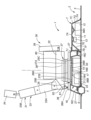
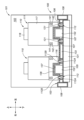
- a cross-sectional view of a vehicle seat mounting structure according to an embodiment.
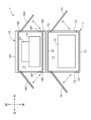
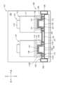
- Horizontal sectional view of vehicle seat mounting structure Explanatory diagram showing the positional relationship of the seat and battery case
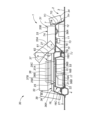
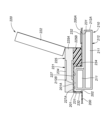
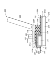
- a sectional view showing a modified example of the sheet form A sectional view showing a modified example of the sheet form
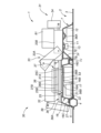
- a sectional view showing a modified example of the sheet form A sectional view of a mounting structure for a vehicle seat according to another embodiment viewed from the front.
- a sectional view of a mounting structure for a vehicle seat according to another embodiment viewed from the front.
- a sectional view of a mounting structure for a vehicle seat according to another embodiment viewed from the front.
- a sectional view of a mounting structure for a vehicle seat according to another embodiment viewed from the front A sectional view of a mounting structure for a vehicle seat according to another embodiment viewed from the front.
- a sectional view of a mounting structure for a vehicle seat according to another embodiment viewed from the front.
- the vehicle is preferably an automobile such as a one-box car.
- a vehicle seat mounting structure 1 has a floor 2.
- the floor 2 includes a plate-shaped floor panel 3 and a plurality of cross members 4 coupled to the floor panel 3.
- a pair of left and right side sills extending longitudinally are connected to the left and right edges of the floor panel 3.
- the plurality of cross members 4 extend left and right at intervals in the front and back.
- the left and right end portions of each of the plurality of cross members 4 are coupled to corresponding side sills on the left and right sides.
- the plurality of cross members 4 are preferably coupled to the lower surface or upper surface of the floor panel 3. Further, the plurality of cross members 4 are preferably formed in a groove shape and cooperate with the floor panel 3 to form a closed cross-sectional structure. In this embodiment, the cross member 4 is coupled to the lower surface of the floor panel 3.
- the floor panel 3 has a convex portion 5 projecting upward in a portion corresponding to the cross member 4. The convex portion 5 extends left and right along the cross member 4. The convex portion 5 improves the rigidity of the floor panel 3.
- a floor box 7 is provided on the upper surface of the floor panel 3.
- the floor box 7 is arranged at a distance rearward from the convex portion 5.
- the floor box 7 includes an upper wall portion 7A whose surface faces upward and downward, a front wall portion 7B which extends downward from the front edge of the upper wall portion 7A and whose surface faces forward and backward, and a front wall portion 7B which extends downward from the rear edge of the upper wall portion 7A.
- a rear wall portion 7C whose surface faces front and back
- left and right side wall portions 7D which extend downward from the left and right side edges of the upper wall portion 7A and whose surfaces face left and right.
- the front edges of the left and right side wall portions 7D are joined to the left and right side edges of the front wall portion 7B.
- the rear edges of the left and right side walls 7D are joined to the left and right side edges of the rear wall 7C.
- the floor box 7 is formed into a box shape that opens downward.
- the lower edge of the front wall 7B, the lower edge of the rear wall 7C, and the lower edges of the left and right side walls 7D are coupled to the upper surface of the floor panel 3.
- the floor panel 3 and the floor box 7 are preferably formed of steel plates.
- the floor box 7 is preferably formed of a steel plate or a resin material.
- the floor box 7 cooperates with the floor panel 3 and forms part of the floor 2.
- a floor storage chamber 11 for storing articles is formed between the floor box 7 and the floor panel 3.
- a first battery 12 is housed in the floor housing chamber 11 .
- other items such as tires and tools may be stored in the floor storage chamber 11 instead of the first battery 12.
- the floor storage chamber 11 be provided with a fan 13 for cooling the first battery 12 .
- the floor box 7 is preferably provided with a plurality of ventilation holes, which are through holes.
- the floor box 7 has a plurality of reinforcing members 7E.
- the plurality of reinforcing members 7E may include, for example, groove-shaped members extending left and right and coupled to the lower surface of the upper wall portion 7A. Further, the plurality of reinforcing members 7E may include a brace 7F that extends upward and backward from the lower end of the front wall portion 7B and is coupled to the lower surface of the upper wall portion 7A.
- a fan 13 is preferably coupled to the reinforcing member 7E.
- an opening 7G is formed in at least one of the top wall 7A, the rear wall 7C, and the left and right side walls 7D.
- the opening 7G is provided with a lid 7H that opens and closes the opening 7G.
- the lid 7H may be coupled to the rear wall 7C, the upper wall 7A, or the left and right side walls 7D, for example, by a hinge.
- the opening 7G may be formed in the floor panel 3. In this case, the lid 7H may be coupled to the floor panel 3 via a hinge.
- the first battery 12 is taken in and out of the floor storage chamber 11 through the opening 7G.
- a shoulder surface 7J facing in the vertical direction is formed at the middle portion of the front wall portion 7B in the vertical direction.
- the lower part of the front wall part 7B projects forward with respect to the upper part of the front wall part 7B.
- a battery case 16 that accommodates the second battery 15 is provided on the floor 2.
- the first battery 12 and the second battery 15 may be a battery that supplies power to a drive source of a vehicle, or a battery that supplies power to an electrical device such as an electronic control device or a navigation system.
- the battery case 16 is formed into a box shape by combining a case lower part 16A and a case upper part 16B.
- a front fastening portion 16C that protrudes forward is provided at the front end of the battery case 16.
- a rear fastening portion 16D that projects rearward is provided at the rear end of the battery case 16.
- the front fastening portion 16C is formed by a flange provided at the front edge of the lower case portion 16A and a flange provided at the front edge of the upper case portion 16B.
- the rear fastening portion 16D is formed by a flange provided at the rear edge of the lower case 16A and a flange provided at the rear edge of the upper case 16B.
- Left and right end walls 16E are preferably provided on the left and right sides of the case lower part 16A and the case upper part 16B.
- a case housing chamber 17 for housing the second battery 15 is formed between the case lower part 16A and the case upper part 16B.
- the battery case 16 is preferably formed of a steel plate or a resin material.
- the battery case 16 is preferably coupled to the floor 2. That is, the battery case 16 is preferably coupled to at least one of the floor panel 3 , the cross member 4 , and the floor box 7 .
- the battery case 16 may be fastened to the floor 2 with fastening members such as bolts and nuts, or may be welded to the floor 2.
- the battery case 16 is placed on the upper surface of the floor panel 3.
- the lower surface of the battery case 16 may be coupled to the upper surface of the floor panel 3.
- the front fastening portion 16C is coupled to the upper surface of the convex portion 5, and the rear fastening portion 16D is coupled to the shoulder surface 7J of the floor box 7.
- the battery case 16 is arranged between the cross member 4 and the floor box 7 in the front-rear direction.
- At least one reinforcing member extending left and right may be provided on the upper surface of the floor panel 3, and the lower surface of the battery case 16 may be coupled to the reinforcing member.
- the battery case 16 has an opening 16F formed therein.
- the opening 16F is provided with a lid 16G that opens and closes the opening 16F.
- the lid 16G may be coupled to the battery case 16 by, for example, a hinge.
- the opening 16F is formed in the left and right end walls 16E of the battery case 16.
- the second battery 15 is taken in and out of the battery housing section through the opening 16F.
- the second battery 15 may be placed at any position in the case storage chamber 17.
- a plurality of ventilation holes which are through holes, are formed in the battery case 16.
- a fan 21 may be arranged inside the battery case 16. Fan 21 draws air into battery case 16 through a plurality of ventilation holes to cool second battery 15 .
- a support member 22 for supporting the fan 21 may be provided in the case storage chamber 17 .
- the support member 22 is preferably flexible and has a function of absorbing shocks applied to the fan 21.
- the support member 22 may be provided below the second battery 15.
- the second battery 15 is arranged at the rear of the case storage chamber 17, the support member 22 is arranged at the front of the second battery 15, and the fan 21 is supported on the upper surface of the support member 22.
- a reinforcing structure 25 is provided on the upper surface of the battery case 16.
- the reinforcing structure 25 extends along the upper surface of the battery case 16 and includes a plurality of reinforcing members 25A to 25C coupled to each other.
- Each reinforcing structure 25 is preferably formed of a channel-shaped steel material, for example.
- the plurality of reinforcing members 25A to 25C are preferably formed into a frame shape when viewed from above.
- the plurality of reinforcing members 25A to 25C include a pair of left and right first members 25A extending in the front and back, a second member 25B extending in the left and right and coupled to the front ends of the left and right first members 25A, and a pair of left and right first members 25A extending in the left and right. It is preferable to include a third member 25C coupled to the rear end of the member 25A. That is, the reinforcing structure 25 is preferably formed into a rectangular shape when viewed from above. Thereby, the reinforcing structure 25 can efficiently reinforce the upper surface of the battery case 16.
- the reinforcing structure 25 may include a reinforcing member 25D extending from the second member 25B to the front fastening portion 16C along the upper surface of the battery case 16. Further, the reinforcing structure 25 may include a reinforcing member 25E extending from the third member 25C to the rear fastening portion 16D along the upper surface of the battery case 16. A plurality of reinforcing beads may be formed on the surface of the battery case 16.
- a seat 30 is placed above the battery case 16 via a plurality of support legs 27.
- the seat 30 has a seat body 31 on which an occupant sits.
- the seat body 31 includes a seat cushion 32 that supports the buttocks of the occupant from below, a seat back 33 that is rotatably supported by the seat cushion 32 and supports the back of the occupant, and is provided at the upper end of the seat back 33 to support the occupant's buttocks.
- the headrest 34 supports the head of the driver.
- the seat 30 also includes a slide device 36 provided at the bottom of the seat body 31 and a rotation device 37 interposed between the seat body 31 and the slide device 36.
- a height adjustment device 38 for changing the height of the seat cushion 32 may be provided between the rotation device 37 and the seat cushion 32.
- the height adjustment device 38 may be formed, for example, by a link mechanism.
- An ottoman 39 may be rotatably provided at the front end of the seat cushion 32.
- the slide device 36, the rotation device 37, the height adjustment device 38, and the ottoman 39 are not essential components and may be omitted in other embodiments.
- the seat back 33 may include a lower seat back 33A rotatably supported by the seat cushion 32 and an upper seat back 33B rotatably supported by the lower seat back 33A.
- the headrest 34 is rotatably supported by the seat back 33.
- the slide device 36 has a pair of left and right lower rails 36A that extend front and rear, and left and right upper rails 36B that are slidably supported by the left and right lower rails 36A.
- the plurality of support legs 27 are coupled to the slide device 36.
- Four plurality of support legs 27 are provided corresponding to the front and rear ends of the left and right lower rails 36A.
- Each support leg 27 extends vertically, is coupled to the floor 2 at its lower end, and is coupled to the front or rear end of the lower rail 36A at its upper end.
- the pair of front support legs 27 coupled to the front ends of the left and right lower rails 36A are coupled to the convex portion 5 at their lower ends.
- the pair of rear support legs 27 connected to the rear ends of the left and right lower rails 36A are connected to the upper wall portion 7A of the floor box 7 at their lower ends.
- the lower end of each support leg 27 may be fastened to the upper surface of the floor panel 3.
- the reinforcing structure 25 is coupled to the left and right lower rails 36A of the seat 30.
- the front and rear ends of the first member 25A may be coupled to the front and rear ends of the left and right lower rails 36A of the seat 30, respectively.
- the reinforcing structure 25 is preferably coupled to each support leg 27 .
- the upper end of each support leg 27 may be disposed between the first member 25A and the lower rail 36A in the vertical direction.
- the upper end of each support leg 27 is preferably fastened together to the first member 25A and the lower rail 36A.
- the reinforcing structure 25 can improve the rigidity of the support leg 27.
- the reinforcing structure 25 can support the seat 30 with good stability.
- the left and right upper rails 36B are connected to the seat cushion 32 via a rotation device 37.
- the rotating device 37 includes a base plate 37A coupled to left and right upper rails 36B, and a rotating plate 37B supported rotatably about a vertical axis on the upper surface of the base plate 37A.
- the rotating plate 37B is connected to the seat cushion 32 via a height adjustment device 38.
- the base plate 37A and the rotating plate 37B are each formed into a plate shape, and are vertically overlapped.
- a thrust bearing is preferably provided between the base plate 37A and the rotating plate 37B. As shown in FIG. 3, at least a portion of the rotating device 37 preferably overlaps the reinforcing structure 25 when viewed from above.
- an electronic control device 53 is arranged inside the reinforcing structure 25 when viewed from above.
- Electronic control device 53 is arranged on the top surface of battery case 16. According to this aspect, the electronic control device 53 can be arranged with good space efficiency by utilizing the space inside the reinforcing structure 25. Moreover, the electronic control device 53 can be arranged with good space efficiency by utilizing the space between the battery case 16 and the seat 30.
- the electronic control device 53 includes a processor such as a CPU, a nonvolatile memory (ROM), a volatile memory (RAM), and the like.
- the electronic control device 53 controls a plurality of electrical devices provided on the seat 30 by executing arithmetic processing in accordance with a program stored in a nonvolatile memory in a processor.
- the electrical equipment includes, for example, an electric motor of the slide device 36, an electric motor of the rotation device 37, an electric motor of the height adjustment device 38, a seat heater provided in the seat cushion 32 and the seat back 33, a blower, and various sensors.
- the sensor may include a first sensor 56A that detects the temperature of the floor storage chamber 11 and the temperature of the first battery 12 disposed in the floor storage chamber 11.
- the first sensor 56A may also detect the humidity within the first battery 12 or the floor housing chamber.
- the first sensor 56A may be provided on either the inner surface of the floor box 7, the reinforcing member 7E of the floor box 7, or the lid 7H. Further, the first sensor 56A may be provided directly on the first battery 12.
- the senor preferably includes a second sensor 56B that detects the temperature of the second battery 15 or the case storage chamber 17.
- the second sensor 56B may also detect the humidity of the second battery 15 or the case housing chamber 17.
- the second sensor 56B may be provided on the inner surface of the battery case 16 or on the outer surface of the battery case 16. Further, the second sensor 56B may be provided directly on the second battery 15 within the battery case 16.
- the second battery 15 preferably overlaps with the reinforcing structure 25 when viewed from above. Further, it is preferable that at least a portion of the second battery 15 overlaps with the electronic control device 53 when viewed from above. According to this aspect, the electronic control device 53 can be arranged between the seat 30 and the second battery 15 with good space efficiency.
- a cover 61 may be provided at the bottom of the seat cushion 32 to hide the rotation device 37 and the height adjustment device 38.
- the cover 61 preferably projects downward from the rear end of the seat cushion 32 and extends left and right.
- a wire harness 62 that connects the electrical equipment of the seat 30 and the electronic control device 53 is preferably supported on the back surface of the cover 61 .
- the ottoman 39 can take an upright position extending upward from the seat cushion 32.
- the ottoman 39 and the seat back 33 can support the luggage 80 placed on the upper surface of the seat cushion 32 from the front and back.
- the seat body 31 faces rearward due to the rotating device 37 rotating 180 degrees.
- the lower seat back 33A extends rearward and downward from the rear end of the seat cushion 32, and the upper seat back 33B extends rearward from the lower seat back 33A along the upper wall 7A of the floor box 7. Can be done.
- the headrest 34 can extend rearward and downward from the upper seat back 33B along the rear wall portion 7C of the floor box 7. In this way, the seat back 33 and the headrest 34 can extend along the floor box 7.
- the headrest 34 can extend upward from the upper seat back 33B. Thereby, the headrest 34 and the lower seat back 33A can support the luggage 81 placed on the upper seat back 33B from the front and rear directions.
- the seat 30 is supported by the battery case 16 via the reinforcing structure 25, so the seat 30 can be supported above the battery case 16 with good stability. Since the rigidity of the battery case 16 is improved by the reinforcing structure 25, the battery case 16 can support the seat 30 with good stability. Further, the battery and the reinforcing structure 25 can be efficiently arranged below the seat 30.
- the floor 103 that constitutes the bottom of the cabin 102 of the vehicle 101 may be constituted by a first floor panel 105 and a second floor panel 106. .
- the surfaces of the first floor panel 105 and the second floor panel 106 face upward and downward.
- the second floor panel 106 is arranged above the first floor panel 105 with a gap in between.
- a spacer 107 may be disposed between the first floor panel 105 and the second floor panel 106.
- the first floor panel 105 is preferably formed of a steel plate.
- the second floor panel 106 is preferably formed of a steel plate or a resin material.
- the left and right side parts of the first floor panel 105 are connected to the left and right side sills 108.
- a plurality of cross members may be coupled to the lower surface of the first floor panel 105. Each cross member preferably extends left and right and is coupled to the left and right side sills 108.
- Each sheet 110 is provided on the top surface of the first floor panel 105.
- Each seat 110 has a seat body 111, a slide device 112, a rotation device 113, and a height adjustment device 114.
- the seat body 111 includes a seat cushion 116, a seat back 117, and a headrest 118.
- Each seat 110 may be a front seat, a mid seat, or a rear seat.
- Each slide device 112 has a pair of left and right lower rails 112A provided on the upper surface of the first floor panel 105, and a pair of left and right upper rails 112B slidably supported by each lower rail 112A.
- Each lower rail 112A extends back and forth.
- a plurality of slits 121 are formed in the second floor panel 106 and extend back and forth along the lower rail 112A.
- Each slit 121 vertically passes through the second floor panel 106.
- Each upper rail 112B may pass through a corresponding slit 121 and protrude above the second floor panel 106.
- the edge of each slit 121 may be supported on the upper surface of each lower rail 112A. That is, each lower rail 112A may support the second floor panel 106 from below. In other embodiments, each lower rail 112A may pass through the slit 121 and protrude above the second floor panel 106.
- the lower rails 112A of the left front seat, mid seat, and rear seat may be connected to each other in the front and rear.
- the lower rails 112A of the right front seat, mid seat, and rear seat may be connected to each other in the front and rear. Thereby, the movement range of each upper rail 112B can be increased.
- each slide device 112 is preferably coupled to the lower part of the rotation device 113.
- An upper portion of a rotating device 113 is supported at the lower portion so as to be rotatable about an axis extending in the vertical direction.
- a thrust bearing may be provided between the lower and upper parts of the rotating device 113.
- a seat cushion 116 is provided above the rotating device 113 via a height adjusting device 114 .
- a first battery 131 is provided below the first floor panel 105.
- the first battery 131 may be supported by the lower surface of the first floor panel 105, a cross member coupled to the first floor panel 105, or the side sill 108.
- a second battery 132 is provided between the first floor panel 105 and the second floor panel 106 and between the left and right lower rails 112A of each seat 110. Further, between the first floor panel 105 and the second floor panel 106, a third battery 133 is provided between the right lower rail 112A of the left seat 110 and the left lower rail 112A of the right seat 110. It is being The right lower rail 112A of the left seat 110 is arranged offset to the left, and the left lower rail 112A of the right seat 110 is arranged offset to the right, thereby creating a space in which the third battery 133 is arranged. can be made larger.
- the second battery 132 and the third battery 133 can be placed between the first floor panel 105 and the second floor panel 106. Since the second floor panel 106 is arranged above the second battery 132 and the third battery 133, the second battery 132 and the third battery 133 are not exposed inside the vehicle interior 102. Furthermore, the second floor panel 106 allows the bottom of the vehicle interior 102 to be simplified.
- a first tunnel portion 135 that bulges upward may be provided at the center of the second floor panel 106 in the left-right direction.
- the first tunnel portion 135 is arranged between the left and right seats 110 and extends back and forth.
- the first tunnel portion 135 allows the space between the first floor panel 105 and the second floor panel 106 to be expanded upward. This makes it possible to arrange the third battery 133 inside the first tunnel portion 135, thereby making it possible to increase the size of the third battery 133.
- a pair of left and right second tunnel portions 136 may be provided between the left and right lower rails 112A of each seat 110.
- a recessed portion 137 that is recessed upward may be formed at the center of the lower portion of the seat cushion 116 in the left-right direction.
- the rotation device 113 and the height adjustment device 114 may be omitted, and the left and right upper rails 112B may be coupled to the bottom of the seat cushion 116.
- the second tunnel portion 136 protrudes into the recess 137 and faces the seat cushion 116 with a gap therebetween.
- a second battery 132 is arranged inside the left and right second tunnel portions 136. The left and right tunnel portions allow the second battery 132 to be made larger.
- the left and right second tunnel portions 136 may extend back and forth. In this case, it is preferable that the recess 137 extends back and forth and reaches the front and rear ends of the seat cushion 116.
- the second tunnel portion 136 and the second battery 132 may extend from below the front seat to below the rear seat.
- the rotation device 113 and the height adjustment device 114 may be arranged inside the seat cushion 116.
- the rotating device 113 is preferably disposed above the recess 137.
- the seat cushion 116 is provided with a vibrating body 141 as a notification device and a speaker 142.
- the vibrating body 141 and the speaker 142 are preferably placed at positions avoiding the recess 137.
- the blower provided on the seat 110 is preferably placed at a position avoiding the recess 137.
- the floor box 7 may be omitted.
- the rear support leg 27 may be directly connected to the floor panel 3.
- the rear fastening portion 16D of the battery case 16 may be directly coupled to the floor panel 3.
- each support leg 27 may be omitted and the slide device 36 may be supported only by the battery case 16.
- a convex portion projecting upward is provided on the floor panel, and a battery unit is disposed inside the convex portion and below the floor panel.
- Vehicles are known. There is a desire to appropriately arrange a seat cushion containing a foamed urethane pad and a foamed polypropylene pad described in JP-A-2018-158096 on such a floor panel.
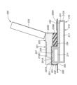
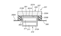
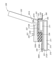
- a convex portion 201 that protrudes upward from the upper surface 200A of the floor panel 200 is provided.
- a battery receiving portion 202 that opens downward is formed below the convex portion 201 .
- the convex portion 201 is preferably formed into a substantially rectangular shape and extends in the front-rear direction and the left-right direction.
- the upper surface 201A of the convex portion 201 preferably extends in the horizontal direction.
- a battery unit 210 is arranged below the floor panel 200.
- Battery unit 210 includes a plurality of batteries 211 and a battery case 212 that receives batteries 211.
- the battery case 212 has a case lower part 212A extending horizontally along the lower surface of the floor panel 200, and a case upper part 212B protruding upward from the upper surface of the case lower part 212A.
- the case lower part 212A is preferably formed into a flat rectangular parallelepiped and extends in the front and rear and left and right directions.
- the case upper part 212B extends upward from the front end of the case lower part 212A and extends in the left-right direction.
- the case upper part 212B protrudes into the battery receiving part 202 below the convex part 201.
- the battery case 212 is preferably coupled to left and right side sills and a plurality of cross members that support the floor panel 200. When viewed from the left and right, the case lower portion 212A extends rearward from below the battery receiving portion 202.
- a sheet 220 is placed and fixed on the floor panel 200.
- the seat 220 has a seat cushion 221 and a seat back 222.
- the seat cushion 221 is placed on at least the upper surface 201A of the convex portion 201.
- the seat cushion 221 includes a pad 225 and a skin material covering the pad 225.
- the frame of the seat cushion 221 may be omitted. Further, the frame of the seat cushion 221 may be provided around the pad 225 or inside the pad 225.
- the pad 225 has a first pad 225A provided at the top and a second pad 225B provided at the bottom of the first pad 225A.
- the second pad 225B is made of a harder material than the first pad 225A.
- the second pad 225B is more difficult to deform than the first pad 225A.
- the second pad 225B supports the first pad 225A from below.
- the second pad 225B may function as a frame.
- the first pad 225A and the second pad 225B are preferably bonded to each other.
- the first pad 225A may be made of urethane foam
- the second pad 225B may be made of polypropylene foam.
- the seat cushion 221 has a recess 227 that receives the protrusion 201.
- the recessed portion 227 is recessed upward from the lower surface of the seat cushion 221.
- the recessed portion 227 is preferably provided at the center of the front portion of the seat cushion 221 in the left-right direction.
- the recess 227 preferably reaches the front end of the seat cushion 221.
- the recess 227 is formed into a substantially rectangular parallelepiped.
- the upper end of the recess 227 is formed by a planar bottom surface 227A.
- the bottom surface 227A extends in the horizontal direction.
- the recess 227 is formed at least in the second pad 225B.
- the recess 227 may be formed in the second pad 225B and the first pad 225A.
- the recess 227 may extend from the second pad 225B to the inside of the first pad 225A. Since the convex portion 201 fits into the concave portion 227, the seat cushion 221 can be placed with good stability on the floor panel 200 on which the convex portion 201 is formed.
- the seat cushion 221 is placed on the floor panel 200, and the convex portion 201 projects into the concave portion 227.
- the upper surface 201A of the convex portion 201 contacts the bottom surface 227A of the recessed portion 227.
- the lower surface of the seat cushion 221 contacts the upper surface 200A of the floor panel 200 at the left and right ends of the rear and front portions.
- the lower part of the seat cushion 221 is preferably formed by a second pad 225B. In the vertical direction, the second pad 225B may be in contact with the upper surface 200A of the floor panel 200, and the first pad 225A may be in contact with the upper surface 201A of the convex portion 201.
- the second pad 225B is used in the thicker portion of the seat cushion 221, so deformation of the seat cushion 221 is suppressed.
- the upper end of the second pad 225B and the lower end of the first pad 225A are preferably arranged at the same height as the upper surface 201A of the convex portion 201.
- the upper surface 201A of the convex portion 201 may be in contact with the lower end of the first pad 225A.
- the upper end of the second pad 225B and the lower end of the first pad 225A may be arranged below or above the upper surface 201A of the convex portion 201.
- the upper surface 201A of the protrusion 201 may be in contact with the second pad 225B.
- the front part of the second pad 225B is placed above the convex part 201, and the rear part of the second pad 225B is placed on the floor panel 200 behind the convex part 201. As shown in FIGS.
- the front and rear portions of the second pad 225B may be integrally formed or may be separated.
- the thickness of the rear part of the second pad 225B is preferably formed to be thicker than the thickness of the front part of the second pad 225B.
- the rear part of the seat cushion 221, which corresponds to the buttocks of the occupant, is more susceptible to the load of the occupant than the front part of the seat cushion 221. Since the thickness of the rear part of the second pad 225B is thicker than the thickness of the front part of the second pad 225B, the seat cushion 221 can efficiently resist the load of the occupant. Further, the seat cushion 221 can provide a comfortable sitting feeling to the occupant. Further, the upper surface of the second pad 225B may be offset downward from the upper surface of the front portion of the second pad 225B.
- the second pads 225B are preferably arranged on the rear, left, and right sides of the convex portion 201.
- the second pad 225B at the front of the seat cushion 221 is arranged at a position that does not overlap with the case lower part 212A when viewed from the top and bottom. has been done.
- the second pad 225B at the front part of the seat cushion 221 is located at a position overlapping the case lower part 212A when viewed from the vertical direction. may be placed.
- a plurality of maintenance holes 231 may be formed in the floor panel 200.
- Each maintenance hole 231 passes through the floor panel 200.
- a removable plug 232 is preferably attached to each maintenance hole 231.
- the maintenance hole 231 is preferably provided at a position behind the seat cushion 221 and facing the battery case 212. Further, the maintenance hole 231 is preferably formed in the front wall of the convex portion 201. In this way, each maintenance hole 231 is preferably placed at a position avoiding the seat cushion 221. This prevents each maintenance hole 231 from being blocked by the seat cushion 221. An operator can access the battery unit 210 from the vehicle interior through the maintenance hole 231.
- a plurality of switches 234 are provided on the seat cushion 221.
- Each switch 234 is preferably a membrane switch or a sheet-like pressure sensor.
- the switch 234 is turned on and off in response to the load of the occupant seated on the seat 220.
- the signal from switch 234 may be used, for example, as a seat belt reminder.
- Each switch 234 is preferably provided on the upper and lower surfaces of the first pad 225A. Some of the switches 234 may be disposed between the lower surface of the first pad 225A and the convex portion 201. That is, when viewed from above, some of the switches 234 may be arranged at positions overlapping with the convex portion 201 and the case upper part 212B. Further, some of the switches 234 may be arranged at positions that do not overlap the second pads 225B when viewed from above. Further, some of the switches 234 may be arranged between the lower surface of the first pad 225A and the upper surface of the second pad 225B. That is, some of the switches 234 may be arranged at positions overlapping with the second pads 225B when viewed from above.
- the concave portion 227 and the convex portion 201 may be arranged corresponding to the rear portion of the seat cushion 221.
- the case upper part 212B is preferably arranged behind the case lower part 212A.
- the maintenance hole 231 is preferably formed in the front of the seat cushion 221 and the rear wall of the convex portion 201.
- Japanese Patent Application Laid-open No. 2015-229440 discloses a hot-air heater that blows warm air into the vehicle interior using heat from engine cooling water, and an electric heater that operates with power supplied from a battery, depending on the remaining battery power.
- This disclosure discloses a heater control device that switches the heater. In such a heater control device, it is desired to reduce the power consumption of the battery while maintaining the thermal comfort of the occupant.
- the vehicle 301 includes a battery 302, a first temperature adjustment device 303, a second temperature adjustment device 304, and a control device 305.
- the battery 302 supplies power to various electrical devices of the vehicle 301.
- the electrical equipment may include a driving motor for driving the vehicle 301.
- the first temperature adjustment device 303 is an air conditioning device provided in the vehicle body.
- the first temperature adjustment device 303 receives power from the battery 302, heats or cools air to adjust its temperature, and discharges the temperature-adjusted air from the air outlet.
- the first temperature control device 303 may include, for example, a compressor, an evaporator, a condenser, and a blower.
- the air outlet is preferably provided in the instrument panel or the roof. That is, the air outlet is arranged at a position away from the occupant seated on the seat.
- the second temperature adjustment device 304 is provided on a seat on which a passenger is seated.
- the second temperature adjustment device 304 includes, for example, at least one of a sheet heater and a sheet blower.
- the sheet-like heater includes a heating wire that receives power from the battery 302 to raise the temperature, and is provided on the seat.
- the blower device includes a blower passage provided in the seat, and a blower and a temperature control section provided in the blower passage. One end of the ventilation passage is connected to a ventilation opening provided on the seating surface of the seat. A blower blows air toward an air outlet.
- the temperature adjustment unit preferably includes at least one of a heater core that receives power from the battery 302 to raise the temperature, and a Peltier element that receives power from the battery 302 and lowers the temperature.
- the second temperature adjustment device 304 is set to consume less power than the first temperature adjustment device 303.
- the first temperature adjustment device 303 adjusts the temperature of the entire vehicle interior, while the second temperature adjustment device 304 locally adjusts the temperature around the passenger seated on the seat.
- the control device 305 includes a processor such as a CPU, a nonvolatile memory (ROM), a volatile memory (RAM), and the like.
- the control device 305 controls the first temperature adjustment device 303 and the second temperature adjustment device 304 by executing arithmetic processing in accordance with a program stored in a nonvolatile memory in a processor.
- the control device 305 is connected to an input section 307 operated by a passenger.
- the input unit 307 is preferably configured with a switch, a touch panel, a touch panel display, or the like.
- the input unit 307 outputs a signal corresponding to the target output of the first temperature adjustment device 303 and the target output of the second temperature adjustment device 304 to the control device 305, for example, in response to an operation by the occupant.
- the input unit 307 corresponds to a total target output of the first temperature adjustment device 303 and the second temperature adjustment device 304 and a target usage ratio of the first temperature adjustment device 303 and the second temperature adjustment device 304.
- a signal may be output to the control device 305.
- the input unit 307 may output a signal corresponding to the target temperature to the control device 305.
- the input unit 307 outputs, for example, the target output of the first temperature adjustment device 303 and the target output of the second temperature adjustment device 304 to the control device 305.
- the target output is preferably set to a value between 0% and 100%.
- the control device 305 is connected to the battery 302 and obtains the SOC (State of Charge) of the battery 302.
- the temperature adjustment control executed by the control device 305 will be described below.
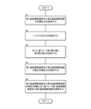
- the control device 305 executes the temperature adjustment control shown in FIG. 19 at predetermined intervals.
- the control device 305 first obtains the target output of the first temperature adjustment device 303 and the target output of the second temperature adjustment device 304 based on the signal from the input unit 307 (S1).
- the control device 305 obtains the SOC of the battery 302 (S2).
- the control device 305 sets a first correction value that is a correction value for the first temperature adjustment device 303 and a second correction value that is a correction value for the second temperature adjustment device 304 based on the SOC ( S3).
- the first correction value is an output to be added to the target output of the first temperature adjustment device 303, and is preferably set to a value of -100% or more and 100% or less.
- the second correction value is an output to be added to the target output of the second temperature adjustment device 304, and is preferably set to a value of -100% or more and 100% or less.
- the first correction value is set to decrease as the SOC decreases.
- the second correction value is set to increase as the SOC decreases.
- the control device 305 preferably sets the first correction value based on the SOC using a map that defines the relationship between the SOC and the first correction value.
- the control device 305 may set the second correction value based on the SOC using a map that defines the relationship between the SOC and the second correction value.
- the control device 305 adds the target output of the first temperature adjustment device 303 and the first correction value to set the corrected target output of the first temperature adjustment device 303, and sets the target output of the second temperature adjustment device 304.
- the output and the second correction value are added to set the corrected target output of the second temperature adjustment device 304 (S4).
- the control device 305 sets the corrected target output of the first temperature adjusting device 303 to 0% when the added value of the target output of the first temperature adjusting device 303 and the first correction value is 0% or less.
- the added value of the target output of the first temperature adjustment device 303 and the first correction value is 100% or more, it is preferable to set the corrected target output of the first temperature adjustment device 303 to 100%.
- control device 305 sets the corrected target output of the second temperature adjusting device 304 to 0% when the added value of the target output of the second temperature adjusting device 304 and the second correction value is 0% or less.
- the added value of the target output of the second temperature adjustment device 304 and the second correction value is 100% or more, it is preferable to set the corrected target output of the second temperature adjustment device 304 to 100%.
- control device 305 controls the first temperature control device 303 based on the corrected target output of the first temperature control device 303, and controls the second temperature control device 303 based on the corrected target output of the second temperature control device 304. 304 (S5).
- the output of the first temperature adjustment device 303 is reduced and the output of the second temperature adjustment device 304 is increased in accordance with the decrease in SCO.
- the total power consumption of the first temperature adjustment device 303 and the second temperature adjustment device 304 can be reduced.
- the second temperature adjustment device 304 locally adjusts the temperature in the vicinity of the occupant seated on the seat, it is possible to maintain temperature-related comfort for the occupant.
- the first correction value and the second correction value may be set to 0.
- the first judgment value is preferably 50%, for example.
- the SOC is greater than or equal to the second determination value and less than the first determination value
- a negative value is set to the first correction value
- a positive value is set to the second correction value.
- the second judgment value is set to a value lower than the first judgment value, and is preferably 30%, for example.
- the first correction value is set to a negative value and the second correction value is set to a positive value. Thereby, the actual output of the first temperature adjustment device 303 is further reduced, and the actual output of the second temperature adjustment device 304 is further increased. At this time, the first correction value may be set to -100% and the first temperature adjustment device 303 may be stopped.
- the control device 305 may stop the temperature adjustment control according to the occupant's selection. Further, the control device 305 may inquire of the occupant whether or not to perform temperature adjustment control when the SOC value reaches a certain determination value. For example, the control device 305 may use a speaker to make an inquiry to the occupant by voice, or may use a display to make an inquiry to the occupant through a screen display. When a decrease in SOC is expected, the control device 305 may inquire of the occupant about starting the temperature adjustment control, or may start the temperature adjustment control without inquiring the occupant. The control device 305 may predict a decrease in SOC based on the outside temperature, for example. Further, the control device 305 may predict a decrease in the SOC based on the gradient on the travel route. Further, the control device 305 may stop the temperature adjustment control when there is a charging station around the vehicle 301.
Landscapes
- Engineering & Computer Science (AREA)
- Transportation (AREA)
- Mechanical Engineering (AREA)
- Aviation & Aerospace Engineering (AREA)
- Chemical & Material Sciences (AREA)
- Combustion & Propulsion (AREA)
- Battery Mounting, Suspending (AREA)
- Arrangement Or Mounting Of Propulsion Units For Vehicles (AREA)
Abstract
Description
2 :フロア
7 :フロアボックス
11 :フロア収容室
12 :第1バッテリ
15 :第2バッテリ
16 :バッテリケース
17 :ケース収容室
25 :補強構造
25A :第1部材
25B :第2部材
25C :第3部材
27 :支持脚
30 :シート
36 :スライド装置
36A :ロアレール
36B :アッパレール
37 :回転装置
37A :ベースプレート
37B :回転プレート
38 :高さ調節装置
53 :電子制御装置
Claims (10)
- 車両用シートの取付構造であって、
フロアと、
前記フロア上に設けられ、バッテリを収容するバッテリケースと、
複数の支持脚を介して前記フロアに結合され、前記バッテリケースの上方に配置されたシートと、
前記バッテリケースの上面に設けられると共に前記シートに結合された補強構造とを有する車両用シートの取付構造。 - 前記補強構造は、前記バッテリケースの上面に沿って延び、互いに結合された複数の補強部材を含み、
複数の前記補強部材は、上方から見て枠形に形成されている請求項1に記載の車両用シートの取付構造。 - 複数の前記補強部材は、前後に延びる左右一対の第1部材と、左右に延び、左右の前記第1部材の前端に結合した第2部材と、左右に延び、左右の前記第1部材の後端に結合した第3部材とを有し、
前記第1部材のそれぞれの前端及び後端が前記シートに結合されている請求項2に記載の車両用シートの取付構造。 - 上方から見て、前記バッテリの少なくとも一部が前記補強構造と重なっている請求項2に記載の車両用シートの取付構造。
- 前記支持脚は、前記シート及び前記補強構造に結合されている請求項2に記載の車両用シートの取付構造。
- 前記シートは、シート本体と、前記シート本体の下部に設けられたスライド装置とを有し、
前記補強構造及び複数の前記支持脚が前記スライド装置に結合している請求項2に記載の車両用シートの取付構造。 - 前記シートは、前記シート本体と前記スライド装置との間に介装された回転装置とを有し、
上方から見て、前記回転装置の少なくとも一部が前記補強構造と重なっている請求項6に記載の車両用シートの取付構造。 - 上方から見て、前記補強構造の内側に電子制御装置が配置されている請求項2に記載の車両用シートの取付構造。
- 前記電子制御装置が、前記バッテリケースの上面に配置されている請求項8に記載の車両用シートの取付構造。
- 上方から見て、前記バッテリの少なくとも一部が前記電子制御装置と重なっている請求項9に記載の車両用シートの取付構造。
Priority Applications (1)
| Application Number | Priority Date | Filing Date | Title |
|---|---|---|---|
| US18/848,449 US20250100423A1 (en) | 2022-04-29 | 2023-04-21 | Vehicle seat mounting structure |
Applications Claiming Priority (6)
| Application Number | Priority Date | Filing Date | Title |
|---|---|---|---|
| US202263363838P | 2022-04-29 | 2022-04-29 | |
| US63/363,838 | 2022-04-29 | ||
| US202263345925P | 2022-05-26 | 2022-05-26 | |
| US63/345,925 | 2022-05-26 | ||
| JP2023066961A JP2023164324A (ja) | 2022-04-29 | 2023-04-17 | 車両用シートの取付構造 |
| JP2023-066961 | 2023-04-17 |
Publications (1)
| Publication Number | Publication Date |
|---|---|
| WO2023210523A1 true WO2023210523A1 (ja) | 2023-11-02 |
Family
ID=88518826
Family Applications (1)
| Application Number | Title | Priority Date | Filing Date |
|---|---|---|---|
| PCT/JP2023/015882 Ceased WO2023210523A1 (ja) | 2022-04-29 | 2023-04-21 | 車両用シートの取付構造 |
Country Status (2)
| Country | Link |
|---|---|
| US (1) | US20250100423A1 (ja) |
| WO (1) | WO2023210523A1 (ja) |
Citations (6)
| Publication number | Priority date | Publication date | Assignee | Title |
|---|---|---|---|---|
| JPH1199832A (ja) * | 1997-09-29 | 1999-04-13 | Daihatsu Motor Co Ltd | 電気自動車のバッテリ搭載構造 |
| WO2014068609A1 (ja) * | 2012-10-30 | 2014-05-08 | 川崎重工業株式会社 | 電動車両および電動車両用バッテリの搬出方法 |
| JP2017024480A (ja) * | 2015-07-17 | 2017-02-02 | 本田技研工業株式会社 | 車両 |
| JP2018075878A (ja) * | 2016-11-07 | 2018-05-17 | トヨタ自動車株式会社 | 車両下部構造 |
| JP2020111168A (ja) * | 2019-01-11 | 2020-07-27 | トヨタ自動車株式会社 | 車両下部構造 |
| JP2021004025A (ja) * | 2019-06-26 | 2021-01-14 | 現代自動車株式会社Hyundai Motor Company | 車体構造物及びこれを含む車両 |
-
2023
- 2023-04-21 WO PCT/JP2023/015882 patent/WO2023210523A1/ja not_active Ceased
- 2023-04-21 US US18/848,449 patent/US20250100423A1/en active Pending
Patent Citations (6)
| Publication number | Priority date | Publication date | Assignee | Title |
|---|---|---|---|---|
| JPH1199832A (ja) * | 1997-09-29 | 1999-04-13 | Daihatsu Motor Co Ltd | 電気自動車のバッテリ搭載構造 |
| WO2014068609A1 (ja) * | 2012-10-30 | 2014-05-08 | 川崎重工業株式会社 | 電動車両および電動車両用バッテリの搬出方法 |
| JP2017024480A (ja) * | 2015-07-17 | 2017-02-02 | 本田技研工業株式会社 | 車両 |
| JP2018075878A (ja) * | 2016-11-07 | 2018-05-17 | トヨタ自動車株式会社 | 車両下部構造 |
| JP2020111168A (ja) * | 2019-01-11 | 2020-07-27 | トヨタ自動車株式会社 | 車両下部構造 |
| JP2021004025A (ja) * | 2019-06-26 | 2021-01-14 | 現代自動車株式会社Hyundai Motor Company | 車体構造物及びこれを含む車両 |
Also Published As
| Publication number | Publication date |
|---|---|
| US20250100423A1 (en) | 2025-03-27 |
Similar Documents
| Publication | Publication Date | Title |
|---|---|---|
| US11420686B2 (en) | Lower vehicle-body structure of electric vehicle | |
| JP4469390B2 (ja) | 車両用シート | |
| JP7501429B2 (ja) | 車体構造 | |
| US7281971B2 (en) | Air conditioner for vehicle | |
| US20200180478A1 (en) | Blower device for rear seat | |
| JP2023099652A (ja) | シートシステム | |
| JP2009006895A (ja) | 車体の側突荷重支持構造および側突荷重支持方法 | |
| WO2022181523A1 (ja) | 自動車の室内温度調節装置及び電気自動車 | |
| JP2018043727A (ja) | 車両用空調装置 | |
| JP3980504B2 (ja) | 車両用空調ダクト構造 | |
| JP7694346B2 (ja) | 車体構造 | |
| WO2004020231A1 (ja) | 乗り物用シート | |
| US20250346094A1 (en) | Conveyance assembly | |
| JP2023087068A5 (ja) | ||
| US20250100423A1 (en) | Vehicle seat mounting structure | |
| JP7589651B2 (ja) | 車両前部構造 | |
| JP2023164324A (ja) | 車両用シートの取付構造 | |
| JP2024077002A (ja) | 車両用シート | |
| JP7804213B2 (ja) | 車両用シート | |
| KR100778593B1 (ko) | 자동차용 냉난방 통풍시트의 열전소자 장착구조 | |
| JP2006232154A (ja) | 車両用換気装置 | |
| JP2025007723A (ja) | 車室構造 | |
| JP7457253B2 (ja) | 車両用シート及び車両 | |
| JP5119042B2 (ja) | 車両用シート | |
| JP4215561B2 (ja) | トラックのキャブの空調装置 |
Legal Events
| Date | Code | Title | Description |
|---|---|---|---|
| 121 | Ep: the epo has been informed by wipo that ep was designated in this application |
Ref document number: 23796265 Country of ref document: EP Kind code of ref document: A1 |
|
| WWE | Wipo information: entry into national phase |
Ref document number: 18848449 Country of ref document: US |
|
| NENP | Non-entry into the national phase |
Ref country code: DE |
|
| WWP | Wipo information: published in national office |
Ref document number: 18848449 Country of ref document: US |
|
| 122 | Ep: pct application non-entry in european phase |
Ref document number: 23796265 Country of ref document: EP Kind code of ref document: A1 |