WO2023210321A1 - 電動工具 - Google Patents
電動工具 Download PDFInfo
- Publication number
- WO2023210321A1 WO2023210321A1 PCT/JP2023/014521 JP2023014521W WO2023210321A1 WO 2023210321 A1 WO2023210321 A1 WO 2023210321A1 JP 2023014521 W JP2023014521 W JP 2023014521W WO 2023210321 A1 WO2023210321 A1 WO 2023210321A1
- Authority
- WO
- WIPO (PCT)
- Prior art keywords
- motor
- section
- housing
- interlocking
- switch
- Prior art date
- Legal status (The legal status is an assumption and is not a legal conclusion. Google has not performed a legal analysis and makes no representation as to the accuracy of the status listed.)
- Ceased
Links
Images

Classifications
-
- B—PERFORMING OPERATIONS; TRANSPORTING
- B25—HAND TOOLS; PORTABLE POWER-DRIVEN TOOLS; MANIPULATORS
- B25B—TOOLS OR BENCH DEVICES NOT OTHERWISE PROVIDED FOR, FOR FASTENING, CONNECTING, DISENGAGING, OR HOLDING
- B25B21/00—Portable power-driven screw or nut setting or loosening tools; Attachments for drilling apparatus serving the same purpose
-
- B—PERFORMING OPERATIONS; TRANSPORTING
- B25—HAND TOOLS; PORTABLE POWER-DRIVEN TOOLS; MANIPULATORS
- B25F—COMBINATION OR MULTI-PURPOSE TOOLS NOT OTHERWISE PROVIDED FOR; DETAILS OR COMPONENTS OF PORTABLE POWER-DRIVEN TOOLS NOT PARTICULARLY RELATED TO THE OPERATIONS PERFORMED AND NOT OTHERWISE PROVIDED FOR
- B25F5/00—Details or components of portable power-driven tools not particularly related to the operations performed and not otherwise provided for
- B25F5/02—Construction of casings, bodies or handles
Definitions
- the present disclosure relates generally to power tools, and more particularly to power tools that include a motor.
- Patent Document 1 discloses a lever-operated electric rotary tool.
- the electric rotary tool described in Patent Document 1 includes a switch lever provided in a part of a grip part casing and a magnetic sensor.
- the magnetic sensor is arranged to face a magnet provided at the displacement portion of the switch lever. Further, the magnetic sensor is connected to the energizing circuit of the electric motor.
- the electric rotary tool described in Patent Document 1 is configured to turn on an energizing circuit and start driving the electric motor by a magnetic sensing operation of a magnetic sensor.
- the present disclosure has been made in view of the above reasons, and an object of the present disclosure is to provide a power tool that can reduce the possibility that the components of the switch section will fail.
- a power tool includes a motor, a switch section, a housing, an operating section, and an interlocking section.
- the motor rotates the tip tool.
- the switch section turns on and off power supply to the motor.
- the housing accommodates the motor.
- the operating section is provided outside the housing, and is displaced between a first position and a second position in response to an operation.
- the interlocking section is displaced between a third position and a fourth position according to displacement of the operating section.
- the housing accommodates the switch section.
- the switch section turns off the power supply to the motor when the interlocking section is located at the third position, and turns off the power supply to the motor when the interlocking section is located at the fourth position. Turn on.
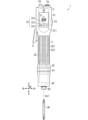
- FIG. 1 is a front view of a power tool according to a first embodiment.
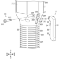
- FIG. 2 is an exploded perspective view of the main parts of the power tool same as above.
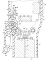
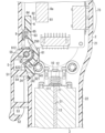
- FIG. 3 is a sectional view showing one state of the power tool same as above.
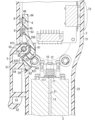
- FIG. 4 is a sectional view showing another state of the power tool same as above.
- FIG. 5 is a sectional view showing one state of the power tool according to the second embodiment.
- FIG. 6 is a sectional view showing another state of the power tool same as above.
- orthogonal (perpendicular) in the present disclosure includes not only a state where the angle between the two is strictly 90 degrees, but also a state where the two are orthogonal within a certain error range. That is, the angle between the two orthogonal angles falls within a certain amount of difference (for example, 10 degrees or less) from 90 degrees. That is, “orthogonal” as used in the present disclosure includes cases where the angle between the two is 80 degrees or more and 100 degrees or less. Similarly, “parallel” in the present disclosure includes not only a state in which the two do not strictly intersect, but also a state in which the two are parallel within a certain degree of difference.
- parallel as used in the present disclosure includes an inclination of one to the other of 10 degrees or less. That is, “parallel” as used in the present disclosure includes cases where the angle between one side and the other is -10 degrees or more and 10 degrees or less.
- a power tool 1 according to the first embodiment is a power tool that can be held by an operator (user) with one hand, for example.
- a tip tool B1 such as a driver bit can be attached to the power tool 1 of the first embodiment.
- the power tool 1 of Embodiment 1 includes a housing 2, a motor 3, an operating section 5, an interlocking section 6 (see FIG. 3), and a first switch section 8 (see FIG. 3).
- the motor 3 rotates the tip tool B1.
- the housing 2 accommodates the motor 3 and the first switch section 8.
- the operating section 5 is provided outside the housing 2.
- the operation unit 5 is displaced between a first position (see FIG. 3) and a second position (see FIG. 4) according to a user's operation.
- the "first position” in the present disclosure includes a position of the operating unit 5 in a state where no push operation is performed by the user, and a position of the operating unit 5 in a state where power supply to the motor 3 is in an OFF state.
- the "second position” as used in the present disclosure includes the position of the operating unit 5 in a state where a push operation is being performed by the user, and the position of the operating unit 5 in a state where power supply to the motor 3 is in an on state.
- the interlocking part 6 is housed in the housing 2.
- the interlocking part 6 is displaced between a third position (see FIG. 3) and a fourth position (see FIG. 4) according to the displacement of the operating part 5.
- the “third position” in the present disclosure includes the position of the interlocking unit 6 when the operating unit 5 is located at the first position, and the position of the interlocking unit 6 where the power supply to the motor 3 is turned off.
- the “fourth position” in the present disclosure refers to the position of the interlocking unit 6 when the operating unit 5 is located at the second position, and the position of the interlocking unit 6 where the power supply to the motor 3 is turned on. include.
- the first switch section 8 turns on and off the power supply to the motor 3 from the external power source.
- the first switch section 8 turns off the power supply to the motor 3 when the interlocking section 6 is located at the third position.
- the first switch section 8 turns on the power supply to the motor 3 when the interlocking section 6 is located at the fourth position.
- the first switch section 8 is provided inside the housing 2
- the first switch section 8 is provided inside the housing 2. It is possible to reduce impact applied to the switch section 8. Therefore, according to the power tool 1 of the first embodiment, it is possible to reduce the possibility that components such as the magnetic sensor of the first switch section 8 will fail.
- the power tool 1 includes a housing 2, a motor 3, a transmission mechanism 41, an output shaft 42, a holding part 43, an operating part 5, and an interlocking part 6. (see FIG. 3), display section 71, operation section 72, forward/reverse selector switch 73, signal connector 74, power connector 75, first switch section 8 (see FIG. 3), elastic member 9 ( (see FIG. 3), a connecting shaft 91 (see FIG. 2), and a second switch section 10 (see FIG. 3).
- the tip tool B1 is not included in the configuration of the power tool 1, but the power tool 1 may include the tip tool B1 in the configuration.
- a direction parallel to the axis Ax1 of the output shaft 42 is defined as an up-down direction.
- the direction from the output shaft 42 to the motor 3 is defined as upward, and the direction from the motor 3 to approach the output shaft 42 is defined as downward.
- housing 2 is formed into a cylindrical shape extending in the vertical direction.
- cylindrical shape as used in the present disclosure includes cylindrical shape, elliptical cylindrical shape, and rectangular cylindrical shape.
- the housing 2 of the first embodiment includes the motor 3, the transmission mechanism 41, at least a part of the output shaft 42, at least a part of the interlocking part 6 (see FIG. 3), and the first switch part 8 (see FIG. 3). , an elastic member 9 (see FIG. 3), and a second switch section 10 (see FIG. 3).
- the housing 2 of Embodiment 1 has a first body part 21, a second body part 22, a third body part 23, a through hole 24 (see FIG. 2), and a recess 25 (see FIG. 2). .
- the first main body portion 21 is formed into a rectangular tube shape with an upper surface.
- the lower surface of the first main body portion 21 is a circular opening.
- the first main body section 21 of the first embodiment accommodates at least a portion of the interlocking section 6, the first switch section 8, the elastic member 9, and the second switch section 10. There is.
- the first main body portion 21 has a first surface 211 and a second surface 212.
- the first surface 211 and the second surface 212 are parallel surfaces.
- the direction in which the first surface 211 and the second surface 212 are lined up is defined as the front-back direction.
- the direction from the second surface 212 to the first surface 211 is defined as the front, and the direction from the first surface 211 to the second surface 212 is defined as the backward direction.
- the front-back direction is perpendicular to the up-down direction.
- a direction perpendicular to the up-down direction and the front-back direction is defined as the left-right direction.
- the front-rear direction and the left-right direction are the radial directions of a virtual circle centered on the axis Ax1 of the output shaft 42.
- a through hole 24 and a recess 25 are formed in the first main body portion 21 of the first embodiment (see FIG. 2).
- the through hole 24 of the first embodiment is formed at the end of the first main body portion 21 in the left-right direction.
- the through hole 24 is formed at a position facing the operating portion 5 in the left-right direction.
- the through hole 24 passes through the first body portion 21 along the thickness direction of the first body portion 21 .
- the shape of the through hole 24 is rectangular when viewed from the left and right.
- the recess 25 in the first embodiment is formed at the end of the first main body 21 in the left-right direction and above the through hole 24.
- the recessed portion 25 is recessed toward the inside of the first main body portion 21 .
- the shape of the recess 25 is rectangular in side view.
- the recess 25 of Embodiment 1 has a bottom wall 250, a front wall 251, and a rear wall 253.
- the bottom wall 250 has a cross-sectional shape of a U-shaped curved plate that is convex toward the inside of the housing 2 .
- the front wall 251 and the rear wall 253 face each other in the front-rear direction.
- the front wall 251 is located in front of the rear wall 253 with a gap.
- a hole 252 is formed in the front wall 251.
- the hole 252 is recessed toward the front.
- the shape of the hole 252 is circular when viewed from the front.
- the hole 252 has a thread formed on its inner peripheral surface. That is, hole 252 is a screw hole.
- the hole 252 fits into the front end of a shaft portion 912 of the connection shaft 91, which will be described later.
- a through hole 254 is formed in the rear wall 253.
- the through hole 254 penetrates the rear wall 253 along the front-rear direction.
- the shape of the through hole 254 is circular when viewed from the front.
- the through hole 254 and the hole 252 overlap in front view.
- the shaft portion 912 of the connecting shaft 91 is passed through the through hole 254 .
- the second main body part 22 protrudes downward from the lower end of the first main body part 21.
- the second main body portion 22 is formed in a cylindrical shape.
- the second main body portion 22 accommodates the motor 3 and at least a portion of the transmission mechanism 41.
- a plurality of convex portions 221 are formed on the side peripheral surface of the second main body portion 22.
- the plurality of convex portions 221 protrude outward from the side peripheral surface of the second main body portion 22 .
- the second main body portion 22 functions as a grip portion that is gripped by the user. Further, the plurality of convex portions 221 function as anti-slip when the second main body portion 22 is gripped by the user.
- the third main body part 23 protrudes downward from the lower end of the second main body part 22.
- the third main body portion 23 is formed in a cylindrical shape.
- the third main body portion 23 accommodates at least a portion of the transmission mechanism 41 and at least a portion of the output shaft 42.
- connection shaft 91 is a fastening member such as a screw.
- the connecting shaft 91 has a head 911 and a shaft portion 912.
- the shape of the head 911 in Embodiment 1 is circular when viewed from the front. Note that the shape of the head 911 may be polygonal when viewed from the front.
- the shaft portion 912 of the first embodiment projects forward from the center of the head 911.
- the shaft portion 912 of the first embodiment is formed in a cylindrical shape extending in the front-rear direction.
- a thread is formed on the outer peripheral surface of the tip (front end) portion of the shaft portion 912 of the first embodiment.
- the shaft portion 912 fits into the hole 252 of the housing 2 while passing through the through hole 254 of the housing 2 and the later-described through hole 551 of the operating portion 5 .
- the connecting shaft 91 is a member that connects the housing 2 and the operating section 5. By removing the connecting shaft 91 from the housing 2, the operating section 5 is removed from the housing 2.
- the signal connector 74 is provided on the upper surface of the housing 2 (first main body portion 21).
- a signal line is connected to the signal connector 74.
- the signal line is a line that connects the power tool 1 and an external device.
- the power tool 1 of the first embodiment exchanges information, for example, regarding determination of quality of tightening work, with an external device via a signal line.
- the power tool 1 may include a communication unit capable of wirelessly communicating with an external device instead of the signal connector 74.
- the power connector 75 is provided on the upper surface of the housing 2.
- the power connector 75 is arranged to be aligned with the signal connector 74 in the left-right direction.
- a power line is connected to the power connector 75.
- the power line is a line that connects the power tool 1 and an external power source.
- the power tool 1 of the first embodiment is supplied with power from an external power source via a power line.
- the power tool 1 may include a mounting portion to which a battery pack can be mounted.
- the motor 3 of the first embodiment converts electric power supplied from an external power source into rotational driving force.
- the motor 3 is, for example, an inner rotor type brushless motor.
- the rotor of the motor 3 rotates around a rotation axis parallel to the vertical direction.
- a through hole 31 is formed in the motor 3 of the first embodiment.
- the through hole 31 of the first embodiment passes through the center of the motor 3 in the vertical direction. More specifically, the through hole 31 passes through the motor shaft of the motor 3 in the vertical direction.
- the transmission mechanism 41 is disposed below the motor 3 in the internal space of the housing 2 (second main body portion 22).
- the transmission mechanism 41 is a mechanism that transmits the rotational driving force generated by the motor 3 to the output shaft 42.
- the transmission mechanism 41 of the first embodiment includes a speed reduction mechanism and a clutch mechanism.
- the speed reduction mechanism is, for example, a planetary gear mechanism.
- the speed reduction mechanism converts the rotational speed and torque of the motor 3 into the rotational speed and torque necessary for tightening work.
- the clutch mechanism interrupts transmission of rotational driving force from the motor 3 to the output shaft 42 when the tightening torque exceeds a predetermined value.
- the clutch mechanism may be implemented, for example, by an electronic clutch.
- the transmission mechanism 41 may include an impact mechanism that applies a rotational impact to the output shaft 42.
- the tip (lower end) of the output shaft 42 is configured such that a tip tool B1 such as a driver bit can be attached and detached.
- a tip tool B1 such as a driver bit
- a driver bit is attached to the output shaft 42, by rotating the driver bit while it is in contact with a fastening member (such as a screw), it is possible to tighten or loosen the fastening member. .
- the holding section 43 is provided at the tip (lower end) of the output shaft 42.
- the holding part 43 is a mechanism for holding the tip tool B1 with respect to the output shaft 42 when the tip tool B1 is attached to the output shaft 42.
- the display section 71 is provided on the first surface 211 of the first main body section 21 (housing 2).
- the display unit 71 of the first embodiment is realized by a two-digit, seven-segment LED (Light Emitting Diode).
- the display section 71 displays the number of fastening parts tightened by the power tool 1.
- the operation section 72 is provided on the first surface 211 of the first main body section 21 (housing 2).
- the operation unit 72 of the first embodiment is realized by three buttons 721.
- the power tool 1 of the first embodiment switches the operation mode according to the user's operations on the three buttons 721.
- the power tool 1 of Embodiment 1 operates in any one of the first mode, second mode, or third mode, for example.
- the first mode is an operation mode in which the output shaft 42 rotates when the operation unit 5 is operated by the user.
- the second mode is an operation mode in which the output shaft 42 rotates when the tip tool B1 is pressed toward the motor 3 (upward).
- the third mode is an operation mode in which the output shaft 42 rotates when the operation unit 5 is operated by the user or when the tip tool B1 is pressed in a direction toward the motor 3.
- the first mode is an operation mode in which the output shaft 42 does not rotate even if the tip tool B1 is pressed in a direction closer to the motor 3.
- the second mode is an operation mode in which the output shaft 42 does not rotate even if the operation unit 5 is operated by the user.
- the forward/reverse switch 73 is provided at the end (right end) of the first main body portion 21 (housing 2) in the left-right direction.
- the forward/reverse selector switch 73 is a switch that switches the rotation direction of the output shaft 42 between forward rotation and reverse rotation.
- the operation unit 5 is provided at the end (left end) of the housing 2 in the left-right direction.
- the operating section 5 of the first embodiment is attached to the housing 2 by the connecting shaft 91 (see FIG. 3).
- the connecting shaft 91 By removing the connecting shaft 91 from the housing 2, the operating section 5 can be removed from the housing 2. That is, the operation unit 5 of the first embodiment is configured to be detachable from the housing 2. For example, when the user uses the power tool 1 in the second mode, the user can use the power tool 1 with the operating section 5 removed from the housing 2, thereby improving convenience.
- the operating section 5 of the first embodiment is an operating lever.
- the operating unit 5 is configured to be rotatable between a first position and a second position around a shaft portion 912 of the connecting shaft 91 in response to a user's operation.
- the operation unit 5 of the first embodiment is located at the first position as shown in FIG. 3 when not pressed by the user. When pressed by the user, the operating section 5 of the first embodiment rotates counterclockwise around the shaft section 912 when viewed from the front, and is displaced from the first position to the second position.
- the operating section 5 includes a base 51 , an edge 52 , a first protrusion 53 , a second protrusion 54 , and a mounting section 55 .
- the base portion 51 is formed into a flat plate shape.
- the base 51 of the first embodiment faces the side peripheral surface of the housing 2 with a gap in the left-right direction. As shown in FIG. 4, the thickness direction of the base portion 51 is along the left-right direction when the operating portion 5 is located at the second position.
- the direction from the base 51 to the housing 2 along the left-right direction is defined as rightward, and the direction from the housing 2 to the base 51 along the left-right direction is defined as leftward.
- the edge 52 is formed along the edge of the base 51.
- the edge 52 protrudes from the base 51 in a direction approaching the housing 2.
- the edge portion 52 protrudes rightward from the base portion 51 when the operating portion 5 is located at the second position.
- the mounting portion 55 protrudes from the upper end of the base portion 51 in a predetermined direction. More specifically, the attachment portion 55 protrudes from the upper end of the base portion 51 toward the recess portion 25 of the housing 2 (first main body portion 21). The attachment portion 55 protrudes rightward from the upper end of the base portion 51 when the operation portion 5 is located at the second position. As shown in FIG. 3, when the operating portion 5 is located at the first position, the upper surface of the mounting portion 55 and the upper wall of the recessed portion 25 are in contact with each other. In other words, the position where the upper surface of the attachment part 55 contacts the upper wall of the recess 25 is the first position of the operating part 5.
- a through hole 551 is formed in the mounting portion 55.
- the through hole 551 is a hole that penetrates the attachment portion 55 along the front-rear direction.
- the shaft portion 912 of the connecting shaft 91 is passed through the through hole 551 .
- the second protruding portion 54 is arranged below the mounting portion 55. More specifically, the second protrusion 54 is arranged below the attachment part 55 and above the first protrusion 53.
- the second protrusion 54 protrudes from the base 51 in a predetermined direction. More specifically, the second protrusion 54 is formed in a cylindrical shape that protrudes from the base 51 toward the through hole 24 of the housing 2 . More specifically, the second protrusion 54 is formed in a cylindrical shape, with the amount of protrusion increasing as it approaches the lower end.
- the second protruding portion 54 protrudes rightward from the base portion 51 when the operating portion 5 is located at the second position.
- the distal end surface (right surface) 541 of the second protrusion 54 has a circular shape in a side view seen from the left and right directions.
- the distal end surface 541 of Embodiment 1 faces upward and to the right.
- the distal end surface 541 contacts and faces a main surface 621 of a cover section 62 of the interlocking section 6, which will be described later, at the first and second positions.
- the second protruding portion 54 (operating portion 5) displaces the cover portion 62 along the penetrating direction of the through hole 24 by being displaced from the first position to the second position.
- the second protruding portion 54 displaces the cover portion 62 toward the inside of the housing 2 (toward the right) by being displaced from the first position to the second position.
- the configurations of the operating portion 5 and the interlocking portion 6 can be simplified.
- the first protrusion 53 is arranged below the second protrusion 54. More specifically, the first protrusion 53 is arranged below the second protrusion 54 and above the lower end of the edge 52 .
- the first protrusion 53 protrudes from the base 51 in a predetermined direction. More specifically, the first protrusion 53 is formed in a cylindrical shape that protrudes from the base 51 toward the second main body 22 of the housing 2 .
- the second protruding portion 54 protrudes rightward from the base portion 51 when the operating portion 5 is located at the second position.
- the second protruding portion 54 of the first embodiment comes into contact with at least one of the side peripheral surface of the second main body portion 22 of the housing 2 and the convex portion 221 when the operating portion 5 is located at the second position. In other words, the position where the second protruding portion 54 contacts at least one of the side peripheral portion of the second main body portion 22 and the convex portion 221 is the second position of the operating portion 5.
- the interlocking section 6 of the first embodiment is a lever member that operates in conjunction with the operating section 5. As shown in FIGS. 3 and 4, at least a portion of the interlocking section 6 is housed in the housing 2 (first main body section 21). As described above, the interlocking part 6 is displaced between the third position (see FIG. 3) and the fourth position (see FIG. 4) in accordance with the displacement of the operating part 5. Specifically, the interlocking unit 6 is located at the third position when the operating unit 5 is at the first position, and is located at the fourth position when the operating unit 5 is at the second position.
- the interlocking part 6 of the first embodiment is arranged at the end (left end) in the left-right direction inside the housing 2.
- the interlocking portion 6 is formed into a curved plate shape.
- the interlocking part 6 includes a bent part 61 , a cover part 62 , an extension part 63 , a tip part 64 , a protrusion part 65 , and a magnet 66 .
- the bent portion 61 is formed into a plate shape bent in a U-shape.
- the bent portion 61 of the first embodiment is bent so as to be convex in the direction away from the operating portion 5 (toward the right).
- the bent portion 61 is bent along the bottom wall 250 of the recess 25 of the housing 2 .
- the cover portion 62 protrudes downward and to the right from the lower end of the bent portion 61.
- the cover portion 62 is arranged to close the through hole 24 of the housing 2. More specifically, the cover part 62 is arranged so as to close the through hole 24 of the housing 2 when located in the third position. Since the cover portion 62 is formed to close the through hole 24 of the housing 2, it is possible to reduce the entry of sand, dust, etc. into the interior of the housing 2.
- the cover portion 62 is displaced toward the inside of the housing 2 when the operating portion 5 (second protruding portion 54) is displaced from the first position to the second position.
- the interlocking part 6 is displaced from the third position to the fourth position when the cover part 62 is pushed by the second protruding part 54 of the operating part 5.
- the cover portion 62 has a main surface 621 and a through hole 622.
- the through hole 622 passes through the cover portion 62 along the front-rear direction.
- the connecting shaft 92 is passed through the through hole 622 .
- the connecting shaft 92 is a cylindrical shaft extending along the front-rear direction.
- the connecting shaft 92 is fixed to the housing 2 while passing through the through hole 622.
- the interlocking part 6 is attached to the housing 2 by the connecting shaft 92.
- the interlocking portion 6 is configured to be rotatable between a third position and a fourth position around a connecting shaft 92 (rotation shaft). More specifically, when the operation unit 5 is pressed by the user, it is displaced from the third position to the fourth position counterclockwise around the rotation axis when viewed from the front.
- the configuration can be simpler than, for example, a configuration in which the interlocking section 6 is displaced in parallel.
- the main surface 621 of the cover portion 62 is a surface facing the outside of the housing 2.
- the main surface 621 is surrounded by an inner peripheral surface that forms the through hole 24 of the housing 2 .
- the main surface 621 of the cover part 62 is arranged to be flush with the surface (side peripheral surface) of the housing 2 when the cover part 62 (interlocking part 6) is located at the third position. Since the main surface 621 of the cover part 62 and the surface of the housing 2 are flush with each other, for example, when the operation part 5 is removed from the housing 2, the user may accidentally touch the main surface 621 of the cover part 62. , the possibility that the power tool 1 will malfunction can be reduced.
- flush as used in the present disclosure includes not only the case of being strictly on the same surface, but also the case of being on substantially the same surface, that is, the case of being substantially flush.
- a and B do not have to be completely flush.
- A is approximately on the same plane as B, and A is slightly protruding (protruding) from B, or A is slightly concave than B.
- the main surface 621 of the cover portion 62 may be slightly recessed from the surface of the housing 2.
- the extension part 63 projects upward from the upper end of the bent part 61.
- the extension portion 63 is formed into a flat plate shape.
- the thickness direction of the extension part 63 is parallel to the left-right direction.
- the tip portion 64 projects upward from the upper end of the extension portion 63.
- the tip portion 64 is formed into a flat plate shape.
- the thickness direction of the tip part 64 is parallel to the left-right direction.
- the tip portion 64 is thicker than the extension portion 63.
- the tip 64 holds a magnet 66.
- the magnet 66 is a permanent magnet such as a neodymium magnet, a ferrite magnet, or a plastic magnet.
- the magnet 66 is arranged to face the first switch section 8 in the left-right direction when the interlocking section 6 is located at the fourth position. More specifically, the magnet 66 is arranged so as to face the first switch section 8 with a slight gap in between when the interlocking section 6 is located at the fourth position. Since the magnet 66 is held (arranged) so as not to come into contact with the first switch section 8, there is a possibility that the magnet 66 or the tip end 64 may come into contact with the first switch section 8 and the components of the first switch section 8 may malfunction. It is possible to reduce the
- the protrusion 65 protrudes leftward from the extension 63.
- the protrusion 65 is formed into a columnar shape.
- the side circumferential portion of the protruding portion 65 in the first embodiment is wound around an elastic member 9 that is a coil spring.
- the elastic member 9 of Embodiment 1 is a helical spring. As described above, the elastic member 9 is wrapped around the protrusion 65 of the interlocking part 6. The right end of the elastic member 9 is in contact with the extension part 63 of the interlocking part 6, and the left end of the elastic member is in contact with the housing 2 (first main body part 21).
- the elastic member 9 allows the interlocking part 6 to move when the operating part 5 is not pressed by the user, that is, when the operating part 5 is located at the first position or when the operating part 5 is removed from the housing 2.
- Force is applied to the interlocking part 6 so that it is located at the third position.
- the elastic member 9 moves the interlocking part 6 so that the main surface 621 of the cover part 62 is flush with the surface (side peripheral surface) of the housing 2 when the operating part 5 is not pressed by the user. Apply force to the extension 63 of.
- the main surface 621 of the cover part 62 and the surface of the housing 2 are flush with each other due to the elastic force of the elastic member 9, the main surface 621 of the cover part 62 and the surface of the housing 2 are flush with each other. condition can be maintained.
- the first switch section 8 of the first embodiment includes a magnetic sensor that detects the magnetism of the magnet 66.
- the first switch section 8 turns on and off the power supply from the external power source to the motor 3 according to the magnetism detected by the magnetic sensor. Since the power supply to the motor 3 can be turned on and off without bringing the interlocking part 6 into contact with the first switch part 8, the possibility that the magnetic sensor of the first switch part 8 breaks down can be reduced. Note that the first switch section 8 turns on and off the power supply from the external power source to the motor 3 by opening and closing the electrical connection between the power supply connector 75 and the motor 3.
- the first switch section 8 turns off the power supply from the external power source to the motor 3 when the distance between the first switch section 8 and the magnet 66 is equal to or greater than a first threshold value. When the distance is less than the first threshold, power supply from the external power source to the motor 3 is turned on. In the first embodiment, when the interlocking section 6 is located at the third position, the distance between the first switch section 8 and the magnet 66 is greater than or equal to the first threshold value. Further, in the first embodiment, when the interlocking section 6 is located at the fourth position, the distance between the first switch section 8 and the magnet 66 is less than the first threshold value.
- the first switch section 8 turns off the power supply to the motor 3 when the interlocking section 6 is located at the third position, and turns off the power supply to the motor 3 when the interlocking section 6 is located at the fourth position. Turn on the power supply to 3.
- the second switch section 10 is arranged above the motor 3.
- the second switch unit 10 turns on the power supply to the motor 3 when the tip tool B1 is displaced toward the side approaching the motor 3 (upward). Note that the second switch unit 10 turns on and off the power supply from the external power source to the motor 3 by opening and closing the electrical connection between the power connector 75 and the motor 3.
- the power tool 1 of Embodiment 1 further includes a holding part 11, a magnet 12, and a drive shaft 13.
- the holding part 11 is arranged above the motor 3.
- the holding part 11 holds a magnet 12. More specifically, the holding part 11 holds the magnet 12 so that the magnet 12 faces the second switch part 10 in the vertical direction.
- the holding part 11 has a recess 111.
- the recess 111 is formed on the lower surface of the holding part 11. The recessed portion 111 is depressed upward.
- the drive shaft 13 is a shaft that passes through the through hole 31 of the motor 3.
- the drive shaft 13 is located below the holding part 11 and above the output shaft 42 (see FIG. 1).
- the drive shaft 13 When the drive shaft 13 receives a force (upward) toward the side where the tip tool B1 (output shaft 42) approaches the motor 3, the drive shaft 13 is displaced toward the holding portion 11 (upward). When the drive shaft 13 is displaced upward, the upper end of the drive shaft 13 is inserted into the recess 111 of the holding part 11. Further, by displacing the drive shaft 13 upward, the drive shaft 13 displaces the holding portion 11 upward. That is, when the user pushes the tip tool B1 toward the motor 3, the magnet 12 held by the holding section 11 approaches the second switch section 10.
- the second switch section 10 has a magnetic sensor that detects the magnetism of the magnet 12.
- the second switch section 10 turns on and off the power supply to the motor 3 according to the magnetism detected by the magnetic sensor.
- the second switch unit 10 turns off power supply to the motor 3 when the distance between the second switch unit 10 and the magnet 12 is equal to or greater than a second threshold value, and turns off the power supply to the motor 3 when the distance between the second switch unit 10 and the magnet 12 is equal to or greater than a second threshold value. If it is less than 2 thresholds, the power supply to the motor 3 is turned on.
- the second switch unit 10 turns on power supply to the motor 3 when the user pushes the tip tool B1 toward the motor 3 and the distance between the second switch unit 10 and the magnet 12 becomes less than a second threshold. state.
- the tip tool B1 can be rotated using two different operating methods, so convenience can be improved. Furthermore, even when the operating section 5 is removed from the housing 2, the power tool 1 can be used.
- the operating unit 5 may be configured to rotate clockwise around the shaft portion 912 when viewed from the front and to be displaced from the first position to the second position when pressed by the user. Further, the operating unit 5 may be configured to move in parallel along the left-right direction, for example, and to be displaced from the first position to the second position when pressed by the user. Further, the interlocking unit 6 is configured to rotate clockwise around the connecting shaft 92 (rotation shaft) when viewed from the front and to be displaced from the third position to the fourth position when the operating unit 5 is pressed by the user. It may be. Further, the interlocking unit 6 may be configured to move in parallel along the left-right direction, for example, and to be displaced from the third position to the fourth position when the operating unit 5 is pressed by the user.
- the distance between the magnet 66 and the first switch section 8 when the interlocking section 6 is located at the third position is the distance between the magnet 66 and the first switch section 8 when the interlocking section 6 is located at the fourth position.
- a case where the distance is longer than the distance between the first switch section 8 and the first switch section 8 is illustrated.
- the distance between the magnet 66 (tip part 64) and the first switch part 8 when the interlocking part 6 is located at the third position is the same as that when the interlocking part 6 is located at the fourth position. It may be shorter than the distance between the magnet 66 and the first switch section 8.
- the first switch section 8 turns off the power supply to the motor 3 when the distance between the first switch section 8 and the magnet 66 is less than the first threshold value, and the first switch section 8 and the magnet 66 When the distance between the motor 3 and the motor 3 is equal to or greater than the first threshold, the power supply to the motor 3 is turned on.
- the power tool 1 according to the second embodiment differs from the power tool 1 according to the first embodiment in that a first switch section 8a is provided instead of the first switch section 8.
- the first switch portion 8a of the second embodiment is arranged to the right of the tip portion 64 of the interlocking portion 6.
- the first switch section 8a is a switch that turns on and off power supply from an external power source to the motor 3 by mechanical operation, such as a microswitch or a limit switch.
- the first switch section 8a includes a main body section 81 and a displacement section 82.
- the main body portion 81 is formed, for example, in the shape of a rectangular parallelepiped.
- the main body part 81 is mounted, for example, on a board housed in the first main body part 21 of the housing 2.
- the displacement part 82 in the second embodiment is, for example, a push button.
- the displacement portion 82 projects leftward from the left surface of the main body portion 81 .
- the displacement portion 82 is formed, for example, in a cylindrical shape.
- the displacement portion 82 is displaced between a fifth position (see FIG. 5) and a sixth position (see FIG. 6).
- the displacement portion 82 of the second embodiment is displaced between the fifth position and the sixth position by moving in parallel along the left-right direction.
- the "fifth position” in the present disclosure includes the position of the displacement part 82 when the interlocking part 6 is located at the third position, and the position of the displacement part 82 where the power supply to the motor 3 is turned off. Furthermore, the “sixth position” in the present disclosure refers to the position of the displacement unit 82 when the interlocking unit 6 is located at the fourth position, and the position of the displacement unit 82 where the power supply to the motor 3 is in the on state. include.
- the first switch section 8a of the second embodiment turns off the power supply from the external power source to the motor 3 when the displacement section 82 is located at the fifth position, and turns off the power supply from the external power source to the motor 3 when the displacement section 82 is located at the sixth position. Turn on the power supply to the motor 3 from the power supply.
- the first switch section 8a of the second embodiment turns off the power supply from the external power source to the motor 3 when the displacement section 82 is pushed toward the main body section 81, and when the displacement section 82 When the motor 3 is not pushed to the side, power supply from an external power source to the motor 3 is turned on.
- the distal end part 64 of the interlocking part 6 pushes the displacement part 82 of the first switch part 8a toward the main body part 81, and the displacing part 82 Position it in the fifth position.
- the distal end portion 64 of the interlocking portion 6 is separated from the displacement portion 82 of the first switch portion 8a when the interlocking portion 6 is located at the fourth position.
- the displacement portion 82 is located at the sixth position. In other words, the distal end portion 64 of the interlocking portion 6 positions the displacement portion 82 at the sixth position when the interlocking portion 6 is located at the fourth position.
- a relatively inexpensive switch such as a microswitch is used as the first switch portion 8a, so there is an advantage that manufacturing costs can be reduced.
- the first switch section 8a turns on the power supply to the motor 3 when the displacement section 82 is pushed into the main body section 81 side, and turns on the power supply to the motor 3 when the displacement section 82 is not pushed into the main body section 81 side.
- the power supply may be turned off.
- the tip portion 64 of the interlocking portion 6 is separated from the displacement portion 82 of the first switch portion 8a when the interlocking portion 6 is located at the third position, and is separated from the displacement portion 82 when the interlocking portion 6 is located at the fourth position. 82 into the main body 81 side.
- the displacement portion 82 of the first switch portion 8a is configured to be displaced between the fifth position and the sixth position by parallel movement or rotational movement along the vertical direction or the front-back direction. It's okay.
- the electric tool (1) includes a motor (3), a switch section (first switch section 8; first switch section 8a), and a housing (2 ), an operating section (5), and an interlocking section (6).
- the motor (3) rotates the tip tool (B1).
- the switch section turns on and off power supply to the motor (3).
- the housing (2) houses the motor (3).
- the operating portion (5) is provided outside the housing (2) and is displaced between a first position and a second position in response to an operation.
- the interlocking part (6) is displaced between the third position and the fourth position according to the displacement of the operating part (5).
- the housing (2) accommodates the switch section.
- the switch section turns off the power supply to the motor (3) when the interlocking section (6) is located at the third position, and turns off the power supply to the motor (3) when the interlocking section (6) is located at the fourth position. Turn on the power supply.
- the switch part (first switch part 8; first switch part 8a) is provided inside the housing (2), when the switch part is exposed to the outside of the housing (2), Compared to this, it is possible to reduce impact applied to the switch section. Therefore, it is possible to reduce the possibility that the components of the switch section will fail.
- the housing (2) has the through hole (24) in the first aspect.
- the through hole (24) is formed at a position facing the operating portion (5).
- the interlocking part (6) has a cover part (62).
- the cover portion (62) is formed to close the through hole (24).
- the operation part (5) displaces the cover part (62) along the penetrating direction of the through hole (24) by being displaced from the first position to the second position.
- the interlocking part (6) is displaced from the third position to the fourth position when the cover part (62) is displaced by the operating part (5).
- the cover part (62) is formed to close the through hole (24) of the housing (2), it is possible to reduce sand, dust, etc. from entering the inside of the housing (2). I can do it.
- the operation part (5) moves the cover part toward the inside of the housing (2) by being displaced from the first position to the second position. (62) is displaced.
- the configuration of the operating section (5) and the interlocking section (6) can be simplified compared to a configuration in which the cover section (62) is displaced toward the outside of the housing (2).
- the main surface (621) of the cover part (62) is configured such that when the interlocking part (6) is located at the third position, It is flush with the surface of the housing (2).
- the main surface (621) of the cover part (62) and the surface of the housing (2) are flush with each other, for example, when the operating part (5) is removed from the housing (2), , it is possible to reduce the possibility that the power tool (1) will malfunction due to the user accidentally touching the main surface (621).
- the power tool (1) according to the fifth aspect further includes an elastic member (9) in any one of the second to fourth aspects.
- the elastic member (9) is connected to the interlocking part (6) so that the main surface (621) of the cover part (62) is flush with the surface of the housing (2) when the operating part (5) is not operated. add force to
- the main surface (621) of the cover part (62) and the surface of the housing (2) become flush with each other due to the force of the elastic member (9), so that the main surface (621) of the cover part (62) ) and the surface of the housing (2) can be maintained flush with each other.
- the operating portion (5) is configured to be detachable from the housing (2).
- the user when the power tool (1) is operated by pushing in the tip tool (B1), for example, the user removes the operation part (5) from the housing (2) and removes the power tool (1) from the power tool (1). can be used to improve convenience.
- the interlocking part (6) has a magnet (66).
- the switch section (first switch section 8) has a magnetic sensor that detects the magnetism of the magnet (66).
- the switch section turns on and off power supply to the motor (3) according to magnetism detected by the magnetic sensor.
- the power supply to the motor (3) can be turned on and off without bringing the interlocking part (6) into contact with the switch part (first switch part 8), which prevents the components of the switch part from malfunctioning.
- the possibility can be reduced.
- the switch portion (first switch portion 8a) is configured to be displaced between the fifth position and the sixth position. (82).
- the switch section turns off the power supply to the motor (3) when the displacement section (82) is located at the fifth position, and turns off the power supply to the motor (3) when the displacement section (82) is located at the sixth position. Turn on the power supply.
- the interlocking part (6) When the interlocking part (6) is located at the third position, the interlocking part (6) positions the displacement part (82) of the switch part at the fifth position.
- the interlocking part (6) positions the displacement part (82) of the switch part at the sixth position.
- the interlocking part (6) is arranged in a third position and a fourth position around the rotation axis (connection shaft 92). It is configured to be rotatable between.
- the interlocking section (6) is configured to be displaced in the rotational direction around the rotation axis (connection shaft 92), so that, for example, the interlocking section (6) is displaced in parallel.
- the configuration can be made simpler.
- a power tool (1) in any one of the first to ninth aspects, includes a second switch section (10) that is different from the first switch section (8; 8a) as a switch section. Prepare more.
- the second switch section (10) turns on power supply to the motor (3) when the tip tool (B1) is displaced toward the motor (3).
- the tip tool (B1) can be rotated using two different operating methods, convenience can be improved. Furthermore, the power tool (1) can be used even when the operating section (5) is removed from the housing (2).
- the configurations other than the first aspect are not essential to the power tool (1) and can be omitted as appropriate.
Landscapes
- Engineering & Computer Science (AREA)
- Mechanical Engineering (AREA)
- Portable Power Tools In General (AREA)
Priority Applications (3)
| Application Number | Priority Date | Filing Date | Title |
|---|---|---|---|
| CN202380033244.7A CN119031996A (zh) | 2022-04-27 | 2023-04-10 | 电动工具 |
| US18/858,661 US20250276428A1 (en) | 2022-04-27 | 2023-04-10 | Electric tool |
| EP23796067.9A EP4516457A4 (de) | 2022-04-27 | 2023-04-10 | Elektrowerkzeug |
Applications Claiming Priority (2)
| Application Number | Priority Date | Filing Date | Title |
|---|---|---|---|
| JP2022-073603 | 2022-04-27 | ||
| JP2022073603A JP7821032B2 (ja) | 2022-04-27 | 2022-04-27 | 電動工具 |
Publications (1)
| Publication Number | Publication Date |
|---|---|
| WO2023210321A1 true WO2023210321A1 (ja) | 2023-11-02 |
Family
ID=88518764
Family Applications (1)
| Application Number | Title | Priority Date | Filing Date |
|---|---|---|---|
| PCT/JP2023/014521 Ceased WO2023210321A1 (ja) | 2022-04-27 | 2023-04-10 | 電動工具 |
Country Status (5)
| Country | Link |
|---|---|
| US (1) | US20250276428A1 (de) |
| EP (1) | EP4516457A4 (de) |
| JP (1) | JP7821032B2 (de) |
| CN (1) | CN119031996A (de) |
| WO (1) | WO2023210321A1 (de) |
Families Citing this family (1)
| Publication number | Priority date | Publication date | Assignee | Title |
|---|---|---|---|---|
| US12667952B1 (en) * | 2025-01-02 | 2026-06-30 | Snap-On Incorporated | Low profile display for power tools |
Citations (4)
| Publication number | Priority date | Publication date | Assignee | Title |
|---|---|---|---|---|
| JP2002254346A (ja) | 2001-02-28 | 2002-09-10 | Katsuyuki Totsu | 電動回転工具の駆動スイッチ方式 |
| JP2012101326A (ja) * | 2010-11-11 | 2012-05-31 | Makita Corp | 変速スイッチ |
| JP2012130989A (ja) * | 2010-12-21 | 2012-07-12 | Hitachi Koki Co Ltd | 回転工具 |
| JP2021107101A (ja) * | 2019-12-27 | 2021-07-29 | 工機ホールディングス株式会社 | 作業機及びフィルタ |
Family Cites Families (3)
| Publication number | Priority date | Publication date | Assignee | Title |
|---|---|---|---|---|
| US10029354B2 (en) * | 2012-10-08 | 2018-07-24 | Robert Bosch Gmbh | Hend-held machine tool |
| DE102013221915B4 (de) * | 2013-10-29 | 2024-12-19 | Robert Bosch Gmbh | Netzbetriebene Handwerkzeugmaschine |
| CN114867583B (zh) * | 2019-12-27 | 2024-11-22 | 工机控股株式会社 | 作业机 |
-
2022
- 2022-04-27 JP JP2022073603A patent/JP7821032B2/ja active Active
-
2023
- 2023-04-10 CN CN202380033244.7A patent/CN119031996A/zh active Pending
- 2023-04-10 WO PCT/JP2023/014521 patent/WO2023210321A1/ja not_active Ceased
- 2023-04-10 EP EP23796067.9A patent/EP4516457A4/de active Pending
- 2023-04-10 US US18/858,661 patent/US20250276428A1/en active Pending
Patent Citations (4)
| Publication number | Priority date | Publication date | Assignee | Title |
|---|---|---|---|---|
| JP2002254346A (ja) | 2001-02-28 | 2002-09-10 | Katsuyuki Totsu | 電動回転工具の駆動スイッチ方式 |
| JP2012101326A (ja) * | 2010-11-11 | 2012-05-31 | Makita Corp | 変速スイッチ |
| JP2012130989A (ja) * | 2010-12-21 | 2012-07-12 | Hitachi Koki Co Ltd | 回転工具 |
| JP2021107101A (ja) * | 2019-12-27 | 2021-07-29 | 工機ホールディングス株式会社 | 作業機及びフィルタ |
Non-Patent Citations (1)
| Title |
|---|
| See also references of EP4516457A4 |
Also Published As
| Publication number | Publication date |
|---|---|
| JP7821032B2 (ja) | 2026-02-26 |
| JP2023162895A (ja) | 2023-11-09 |
| EP4516457A1 (de) | 2025-03-05 |
| EP4516457A4 (de) | 2025-08-20 |
| CN119031996A (zh) | 2024-11-26 |
| US20250276428A1 (en) | 2025-09-04 |
Similar Documents
| Publication | Publication Date | Title |
|---|---|---|
| JP7350523B2 (ja) | 動力工具 | |
| JP5541497B2 (ja) | 電動工具 | |
| JP5510887B2 (ja) | 電動工具 | |
| JP7412263B2 (ja) | 電動工具 | |
| CN112238411A (zh) | 电动工具及旋转工具 | |
| CN111421511A (zh) | 电动工具 | |
| US20130055574A1 (en) | Power tool with replaceable blade | |
| JP5420342B2 (ja) | 電動工具 | |
| WO2012081283A1 (ja) | 車両用電動ロック装置 | |
| JP7412187B2 (ja) | グラインダ | |
| JP7821032B2 (ja) | 電動工具 | |
| WO2004023629A1 (ja) | モータ | |
| JP5003223B2 (ja) | 電動工具 | |
| WO2017110229A1 (ja) | 回転工具 | |
| JP2024085860A (ja) | スロットルグリップ装置 | |
| JP5394361B2 (ja) | 車両用電動ロック装置 | |
| JP2016165767A (ja) | 回転打撃工具 | |
| JP5709087B2 (ja) | 電動工具 | |
| JP7426831B2 (ja) | インパクト工具 | |
| JP6417250B2 (ja) | 電動工具 | |
| JP7837146B2 (ja) | 電動工具 | |
| JP7712574B2 (ja) | 作業機 | |
| JP2019000982A (ja) | 動力工具 | |
| JP7832489B2 (ja) | 作業機 | |
| US20250091191A1 (en) | Power tool with multiple actuator configurations |
Legal Events
| Date | Code | Title | Description |
|---|---|---|---|
| 121 | Ep: the epo has been informed by wipo that ep was designated in this application |
Ref document number: 23796067 Country of ref document: EP Kind code of ref document: A1 |
|
| WWE | Wipo information: entry into national phase |
Ref document number: 202380033244.7 Country of ref document: CN |
|
| WWE | Wipo information: entry into national phase |
Ref document number: 18858661 Country of ref document: US |
|
| WWE | Wipo information: entry into national phase |
Ref document number: 2023796067 Country of ref document: EP |
|
| NENP | Non-entry into the national phase |
Ref country code: DE |
|
| ENP | Entry into the national phase |
Ref document number: 2023796067 Country of ref document: EP Effective date: 20241127 |
|
| WWP | Wipo information: published in national office |
Ref document number: 18858661 Country of ref document: US |