WO2023210316A1 - 駆動装置及び駆動装置ユニット - Google Patents
駆動装置及び駆動装置ユニット Download PDFInfo
- Publication number
- WO2023210316A1 WO2023210316A1 PCT/JP2023/014485 JP2023014485W WO2023210316A1 WO 2023210316 A1 WO2023210316 A1 WO 2023210316A1 JP 2023014485 W JP2023014485 W JP 2023014485W WO 2023210316 A1 WO2023210316 A1 WO 2023210316A1
- Authority
- WO
- WIPO (PCT)
- Prior art keywords
- flow path
- motor
- inverter
- fin
- cover
- Prior art date
- Legal status (The legal status is an assumption and is not a legal conclusion. Google has not performed a legal analysis and makes no representation as to the accuracy of the status listed.)
- Ceased
Links
Images


Classifications
-
- H—ELECTRICITY
- H02—GENERATION; CONVERSION OR DISTRIBUTION OF ELECTRIC POWER
- H02K—DYNAMO-ELECTRIC MACHINES
- H02K9/00—Arrangements for cooling or ventilating
- H02K9/02—Arrangements for cooling or ventilating by ambient air flowing through the machine
- H02K9/04—Arrangements for cooling or ventilating by ambient air flowing through the machine having means for generating a flow of cooling medium
- H02K9/06—Arrangements for cooling or ventilating by ambient air flowing through the machine having means for generating a flow of cooling medium with fans or impellers driven by the machine shaft
-
- B—PERFORMING OPERATIONS; TRANSPORTING
- B64—AIRCRAFT; AVIATION; COSMONAUTICS
- B64D—EQUIPMENT FOR FITTING IN OR TO AIRCRAFT; FLIGHT SUITS; PARACHUTES; ARRANGEMENT OR MOUNTING OF POWER PLANTS OR PROPULSION TRANSMISSIONS IN AIRCRAFT
- B64D27/00—Arrangement or mounting of power plants in aircraft; Aircraft characterised by the type or position of power plants
- B64D27/02—Aircraft characterised by the type or position of power plants
- B64D27/30—Aircraft characterised by electric power plants
- B64D27/34—All-electric aircraft
-
- B—PERFORMING OPERATIONS; TRANSPORTING
- B64—AIRCRAFT; AVIATION; COSMONAUTICS
- B64D—EQUIPMENT FOR FITTING IN OR TO AIRCRAFT; FLIGHT SUITS; PARACHUTES; ARRANGEMENT OR MOUNTING OF POWER PLANTS OR PROPULSION TRANSMISSIONS IN AIRCRAFT
- B64D33/00—Arrangement in aircraft of power plant parts or auxiliaries not otherwise provided for
- B64D33/08—Arrangement in aircraft of power plant parts or auxiliaries not otherwise provided for of power plant cooling systems
- B64D33/10—Radiator arrangement
-
- B—PERFORMING OPERATIONS; TRANSPORTING
- B64—AIRCRAFT; AVIATION; COSMONAUTICS
- B64U—UNMANNED AERIAL VEHICLES [UAV]; EQUIPMENT THEREFOR
- B64U20/00—Constructional aspects of UAVs
- B64U20/90—Cooling
- B64U20/94—Cooling of rotors or rotor motors
-
- B—PERFORMING OPERATIONS; TRANSPORTING
- B64—AIRCRAFT; AVIATION; COSMONAUTICS
- B64U—UNMANNED AERIAL VEHICLES [UAV]; EQUIPMENT THEREFOR
- B64U50/00—Propulsion; Power supply
- B64U50/10—Propulsion
- B64U50/19—Propulsion using electrically powered motors
-
- H—ELECTRICITY
- H02—GENERATION; CONVERSION OR DISTRIBUTION OF ELECTRIC POWER
- H02K—DYNAMO-ELECTRIC MACHINES
- H02K5/00—Casings; Enclosures; Supports
- H02K5/04—Casings or enclosures characterised by the shape, form or construction thereof
- H02K5/18—Casings or enclosures characterised by the shape, form or construction thereof with ribs or fins for improving heat transfer
-
- H—ELECTRICITY
- H02—GENERATION; CONVERSION OR DISTRIBUTION OF ELECTRIC POWER
- H02K—DYNAMO-ELECTRIC MACHINES
- H02K5/00—Casings; Enclosures; Supports
- H02K5/04—Casings or enclosures characterised by the shape, form or construction thereof
- H02K5/20—Casings or enclosures characterised by the shape, form or construction thereof with channels or ducts for flow of cooling medium
- H02K5/207—Casings or enclosures characterised by the shape, form or construction thereof with channels or ducts for flow of cooling medium with openings in the casing specially adapted for ambient air
-
- H—ELECTRICITY
- H02—GENERATION; CONVERSION OR DISTRIBUTION OF ELECTRIC POWER
- H02K—DYNAMO-ELECTRIC MACHINES
- H02K9/00—Arrangements for cooling or ventilating
- H02K9/02—Arrangements for cooling or ventilating by ambient air flowing through the machine
-
- H—ELECTRICITY
- H02—GENERATION; CONVERSION OR DISTRIBUTION OF ELECTRIC POWER
- H02K—DYNAMO-ELECTRIC MACHINES
- H02K9/00—Arrangements for cooling or ventilating
- H02K9/22—Arrangements for cooling or ventilating by solid heat conducting material embedded in, or arranged in contact with, the stator or rotor, e.g. heat bridges
- H02K9/227—Heat sinks
Definitions
- the disclosure in this specification relates to a drive device and a drive device unit.
- Patent Document 1 discloses an electronic module mounted on an aircraft.
- This electronic module is a drive device that drives a propulsion device mounted on an aircraft.
- the electronic module has an inverter and a case.
- the case has a cylindrical portion and heat radiation fins.
- the cylindrical portion extends in the axial direction and houses the inverter.
- the radiation fins are provided on the outer surface of the cylindrical part.
- a plurality of heat radiation fins are arranged in the axial direction.
- Patent Document 1 in an electronic module, when gas such as air flows in the axial direction as a cooling airflow, the heat radiation effect of the radiation fins tends to be higher due to the cooling airflow.
- a plurality of radiation fins are arranged in the axial direction. Therefore, the heat radiation fins on the downstream side exchange heat with the heat radiation fins on the upstream side and the cooling air flow whose temperature has increased. Therefore, the heat dissipation effect of the cooling air tends to be lower in the downstream side radiation fins than in the upstream side fins.
- the main objective of the present disclosure is to provide a drive device and a drive device unit that can enhance the heat dissipation effect.
- the disclosed aspects include: A drive device for rotating a rotor of a flying object, A heat generating part that generates heat due to the drive to rotate the rotor; A housing having an outer peripheral surface extending along the rotational axis of a fan that flows gas and housing a heat generating part; an upstream fin that is provided on the outer peripheral surface and releases heat from the heat generating part to gas; A downstream fin that is provided on the outer circumferential surface on the downstream side of the upstream fin with respect to the gas flow in the axial direction of the rotation axis, and that releases heat from the heat generating part to the gas; A first channel in which an upstream fin is provided and a second channel in which a downstream fin is provided are formed between the outer peripheral surface, and the outer periphery is arranged so that the gas flows through the first channel and the second channel.
- a housing cover covering the surface; a first inlet that is included in the first flow path and allows gas to flow into the first flow path from outside the housing cover without passing through the second flow path; a second inlet that is included in the second flow path and allows gas to flow into the second flow path from outside the housing cover without passing through the first flow path;
- the second inlet port allows the gas outside the housing cover to flow into the second flow path without passing through the first flow path.
- gas that has not absorbed heat from the upstream fins flows into the second flow path from the second inlet.
- the ability of the gas flowing into the second flow path to absorb the heat of the downstream fins in the second flow path is reduced because the heat of the upstream fins has already been absorbed in the first flow path. This can be avoided. Therefore, the heat dissipation effect of the downstream fins in the second flow path can be enhanced by the gas that has not passed through the first flow path. Thereby, the heat dissipation effect of the drive device can be enhanced.
- the disclosed aspects include: A drive unit mounted on a flying object, a drive device that drives a rotor of the aircraft to rotate; A fan that rotates around a rotation axis to send gas and is arranged in a drive device along the rotation axis; Equipped with The drive device is A heat generating part that generates heat due to the drive to rotate the rotor; a housing having an outer circumferential surface extending along the rotational axis and housing a heat generating part; an upstream fin that is provided on the outer peripheral surface and releases heat from the heat generating part to gas; A downstream fin that is provided on the outer circumferential surface on the downstream side of the upstream fin with respect to the gas flow in the axial direction of the rotation axis, and that releases heat from the heat generating part to the gas; A first channel in which an upstream fin is provided and a second channel in which a downstream fin is provided are formed between the outer peripheral surface, and the outer periphery is arranged so that the gas flows through the first channel and the second channel.
- a housing cover covering the surface; a first inlet that is included in the first flow path and allows gas to flow into the first flow path from outside the housing cover without passing through the second flow path; a second inlet that is included in the second flow path and allows gas to flow into the second flow path from outside the housing cover without passing through the first flow path;
- This is a drive device unit having a.
- the same effects as the above drive device can be achieved. Therefore, the heat dissipation effect of the drive device unit can be enhanced.
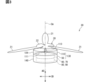
- FIG. 3 is a diagram showing the configuration of an eVTOL in the first embodiment.
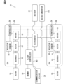
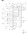
- FIG. 2 is a block diagram showing the electrical configuration of EDS in eVTOL.
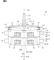
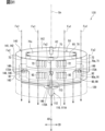
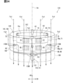
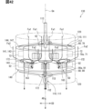
- FIG. 3 is a perspective view of a rotor and an EDS unit. A perspective view of EDS.
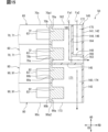
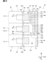
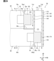
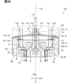
- FIG. 3 is a vertical cross-sectional view of the EDS and the fin cover.
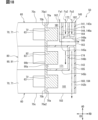
- FIG. 3 is a vertical cross-sectional view of the EDS and fin cover around the first outlet.
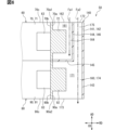
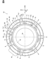
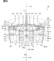
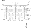
- FIG. 8 is a cross-sectional view taken along line VIII-VIII in FIG. 7, and is a cross-sectional view of the motor and the fin cover.
- FIG. 8 is a sectional view taken along the line IX-IX in FIG.
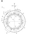
- FIG. 7 is a cross-sectional view of the inverter and the fin cover.
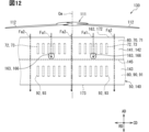
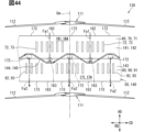
- FIG. 3 is a partially expanded view of the outer peripheral surface of the EDS and the fin cover.
- FIG. 7 is a cross-sectional view of a motor and a fin cover in a second embodiment.
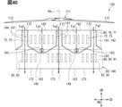
- FIG. 3 is a partially expanded view of the outer peripheral surface of the EDS and the fin cover.
- FIG. 7 is a perspective view of an EDS and a fin cover in a third embodiment.
- FIG. 3 is a vertical cross-sectional view of the EDS and the fin cover.
- FIG. 3 is a vertical cross-sectional view of the EDS and fin cover around the first outlet.
- FIG. 7 is a perspective view of an EDS and a fin cover in a fourth embodiment.
- FIG. 3 is a vertical cross-sectional view of the EDS and the fin cover.
- FIG. 3 is a vertical cross-sectional view of the EDS and fin cover around the first outlet.
- FIG. 6 is a vertical cross-sectional view of the EDS and fin cover around the second outlet.
- FIG. 7 is a perspective view of an EDS and a fin cover in a fifth embodiment.
- FIG. 3 is a vertical cross-sectional view of the EDS and the fin cover.
- FIG. 3 is a vertical cross-sectional view of the EDS and fin cover around the first outlet.
- FIG. 7 is a perspective view of an EDS and a fin cover in a sixth embodiment.
- FIG. 3 is a vertical cross-sectional view of the EDS and the fin cover.
- FIG. 3 is a vertical cross-sectional view of the EDS and fin cover around the first outlet.
- FIG. 7 is a perspective view of an EDS and a fin cover in a seventh embodiment.
- FIG. 3 is a vertical cross-sectional view of the EDS and the fin cover.
- FIG. 3 is a vertical cross-sectional view of the EDS and fin cover around the first outlet.
- FIG. 7 is a vertical cross-sectional view of an EDS and a fin cover in an eighth embodiment.
- FIG. 3 is a vertical cross-sectional view of the EDS and fin cover around the first outlet.
- FIG. 7 is a perspective view of an EDS and a fin cover in a ninth embodiment.
- FIG. 3 is a vertical cross-sectional view of the EDS and the fin cover.
- FIG. 6 is a vertical cross-sectional view of the EDS and fin cover around the second inlet.
- FIG. 7 is a perspective view of an EDS and a fin cover in a tenth embodiment.
- FIG. 6 is a vertical cross-sectional view of the EDS and fin cover around the second inlet.
- FIG. 7 is a perspective view of an EDS and a fin cover in an eleventh embodiment.
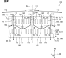
- FIG. 3 is a partially expanded view of the outer peripheral surface of the EDS and the fin cover. A partially expanded view of the outer peripheral surface of the EDS.
- FIG. 7 is a perspective view of an EDS and a fin cover in a twelfth embodiment.
- FIG. 3 is a partially expanded view of the outer peripheral surface of the EDS and the fin cover.
- FIG. 7 is a perspective view of an EDS and a fin cover in a thirteenth embodiment.
- FIG. 3 is a partially expanded view of the outer peripheral surface of the EDS and the fin cover.
- the drive system 30 shown in FIG. 1 is installed in the eVTOL 10.
- the eVTOL 10 is an electric vertical takeoff and landing aircraft, and is capable of vertical takeoff and landing.
- eVTOL is an abbreviation for electric Vertical Take-Off and Landing aircraft.
- the eVTOL 10 is an aircraft that flies in the atmosphere and corresponds to a flying object.
- the eVTOL 10 is also an electric aircraft and is sometimes referred to as an electric aircraft.
- the eVTOL 10 is a manned aircraft on which a crew member rides.
- the drive system 30 is a system that drives the eVTOL 10 to fly.
- the eVTOL 10 has a body 11 and a rotor 20.
- the fuselage 11 has a fuselage main body 12 and wings 13.
- the fuselage main body 12 is the fuselage of the fuselage 11, and has a shape that extends from front to back, for example.
- the fuselage main body 12 has a crew compartment for a crew member to ride.
- the wings 13 extend from the fuselage main body 12, and a plurality of wings 13 are provided in the fuselage main body 12.
- Wing 13 is a fixed wing.
- the plurality of wings 13 include a main wing, a tail wing, and the like.
- a plurality of rotors 20 shown in FIGS. 1 and 3 are provided in the fuselage 11.
- the rotor 20 is provided on each of the fuselage main body 12 and the wings 13.
- the rotor 20 rotates around the rotor axis.
- the rotor axis coincides with a rotation axis Cm, which will be described later.
- the rotor 20 rotates around a rotation axis Cm.
- the rotor 20 has blades 21, a rotor head 22, and a rotor shaft 23.
- a plurality of blades 21 are arranged in the circumferential direction of the rotor axis.
- the rotor head 22 connects a plurality of blades 21.
- the blades 21 extend from the rotor head 22 in the radial direction of the rotor axis.
- the blade 21 is a vane that rotates together with the rotor shaft 23.
- the rotor shaft 23 is a rotation axis of the rotor 20 and extends from the rotor head 22 along the rotor axis.
- the rotor axis is, for example, the center line of the rotor shaft 23.
- the eVTOL 10 is a tilt rotor machine.
- the rotor 20 can be tilted. That is, the tilt angle of the rotor 20 is adjustable.
- the rotor 20 when the eVTOL 10 moves up, the orientation of the rotor 20 is set so that the rotor axis extends in the vertical direction.
- the rotor 20 functions as a lift rotor for generating lift on the eVTOL 10. That is, the rotor 20 can function as a rotary blade.
- the orientation of the rotor 20 is set so that the rotor axis extends in the front-rear direction. In this case, the rotor 20 functions as a cruise rotor for generating thrust in the eVTOL 10.
- the wings 13 can be tilted relative to the fuselage main body 12. That is, it is possible to tilt the rotor 20 together with the blades 13.
- the tilt angle of the rotor 20 is adjusted by adjusting the inclination angle of the wings 13 with respect to the fuselage main body 12.
- the rotor 20 may be able to tilt relative to the aircraft body 11.
- the tilt angle of the rotor 20 may be adjusted by adjusting the relative inclination angle of the rotor 20 with respect to the blades 13.
- the drive system 30 includes a battery 31, a distributor 32, a converter 33, a communication device 34, a storage device 35, a flight control device 40, and an EDS 50.
- the rotor 20 is shown as Rotor
- the battery 31 as Battery
- the distributor 32 as Distributor
- the converter 33 as DC-DC converter.
- the communication device 34 is shown as a Communication Device
- the storage device 35 is shown as a Memory
- the flight control device 40 is shown as a Flight Controller.
- the battery 31 is electrically connected to the plurality of EDSs 50.
- the battery 31 is a power supply section that supplies power to the EDS 50, and corresponds to a power supply section.
- the battery 31 is a DC voltage source that applies DC voltage to the EDS 50.
- the battery 31 has a secondary battery that can be charged and discharged. Examples of this secondary battery include a lithium ion battery and a nickel hydride battery. Note that, in addition to or in place of the battery 31, a fuel cell, a generator, or the like may be used as the power supply section.
- the distributor 32 is electrically connected to the battery 31 and the plurality of EDSs 50.
- Distributor 32 distributes power from battery 31 to a plurality of EDSs 50.
- a drive unit 81 which will be described later, is electrically connected to the distributor 32. Power from the battery 31 is supplied to the drive section 81 via the distributor 32.
- the high voltage is applied to the drive unit 81.
- the distributor 32 may not be provided.
- An example of a configuration that does not require the distributor 32 is a configuration in which each of the plurality of EDSs 50 is individually provided with a power supply section.
- the flight control device 40 is, for example, an ECU, and controls the driving of the EDS 50.
- ECU is an abbreviation for Electronic Control Unit.
- the flight control device 40 is mainly composed of a microcomputer including, for example, a processor, memory, I/O, and a bus connecting these.
- a microcomputer is sometimes called a microcomputer.
- Memory is a non-transitory, tangible storage medium that non-temporarily stores computer-readable programs and data. Further, the non-transitory tangible storage medium is a non-transitory tangible storage medium, and is realized by a semiconductor memory, a magnetic disk, or the like.
- the flight control device 40 is electrically connected to the storage device 35 and the EDS 50.
- the flight control device 40 executes various processes related to driving the EDS 50 by executing a control program stored in at least one of the memory and the storage device 35.
- Flight control device 40 performs flight control for causing eVTOL 10 to fly.
- This flight control includes control of the EDS 50, tilt angle control for changing the tilt angle of the rotor 20, and the like.
- a drive control section 54 which will be described later, is electrically connected to the flight control device 40.
- the flight control device 40 controls the EDS 50 by outputting a control signal to the drive control section 54.
- the converter 33 is electrically connected to the battery 31, flight control device 40, and EDS 50.
- a drive control section 54 is electrically connected to the converter 33.
- Converter 33 steps down or steps up the power from battery 31 and supplies it to flight control device 40 and drive control section 54 .
- the voltage of the power stepped down by the converter 33 is referred to as a low voltage
- the low voltage is applied to the flight control device 40 and the drive control unit 54.
- This low voltage is a voltage lower than the voltage of the battery 31.
- the voltage of the power boosted by the converter 33 is referred to as a high voltage
- the high voltage is applied to the flight control device 40 and the drive control unit 54. This high voltage is higher than the voltage of the battery 31.
- the EDS 50 is a device that drives the rotor 20 to rotate, and corresponds to a drive device.
- the EDS 50 rotates with respect to the rotor 20.
- EDS50 is an abbreviation for Electric Drive System.
- EDS 50 is sometimes referred to as an electric drive unit and EPU.
- EPU is an abbreviation for Electric Propulsion Unit.
- the EDS 50 is provided individually for each of the plurality of rotors 20.
- the EDSs 50 are arranged on the rotor 20 along the rotor axis. All of the plurality of EDSs 50 are fixed to the aircraft body 11.
- the EDS 50 rotatably supports the rotor 20.
- EDS 50 is mechanically connected to rotor shaft 23.
- the plurality of EDSs 50 include at least one of an EDS 50 fixed to the aircraft body 11 in a state of protruding from the outside of the aircraft body 11, and an EDS 50 fixed to the aircraft body 11 in a state of being embedded inside the aircraft body 11. .
- the rotor 20 is fixed to the fuselage 11 via the EDS 50.
- the EDS 50 is designed to prevent tilting relative to the rotor 20.
- the EDS 50 can be tilted together with the rotor 20 relative to the fuselage 11. When the tilt angle of the rotor 20 is adjusted, the orientation of the EDS 50 is set together with the rotor 20.
- the EDS 50 includes a gearbox 53, a drive control section 54, a rotation sensor 55, a motor 61, and a drive section 81.
- the gearbox 53 is shown as a Gearbox
- the drive section 81 as a Driver
- the drive control section 54 as a Controller
- the rotation sensor 55 as a Rotation sensor
- the motor 61 as a Motor.
- the motor 61 is a multi-phase AC motor, for example, a three-phase AC rotating electric machine.
- the motor 61 functions as an electric motor that is a flight drive source for the eVTOL 10.
- the motor 61 has a rotor and a stator 63 (see FIG. 6).
- Stator 63 is a stator.
- the rotor is a rotor and rotates relative to the stator 63.
- Motor 61 is electrically connected to drive section 81 . Electric power is supplied to the motor 61 from the battery 31 via the drive unit 81 .
- the motor 61 is driven according to the voltage and current supplied from the drive section 81.
- As the motor 61 for example, a brushless motor is used. Note that as the motor 61, an induction motor or a reactance motor may be used.
- the gearbox 53 mechanically connects the motor 61 and the rotor 20.
- the rotor shaft 23 is mechanically connected to the rotating shaft of the motor 61 via a gear box 53.
- Gearbox 53 reduces the rotation speed of motor 61 and transmits the speed to rotor 20 .
- the gearbox 53 is configured to include a plurality of gears, and is sometimes referred to as a speed change gear or a speed reducer.
- the gearbox 53 has a structure that matches the motor characteristics of the motor 61.
- the drive unit 81 drives the motor 61 by converting the electric power supplied to the motor 61.
- the drive section 81 has an inverter.
- the inverter converts the power supplied to the motor 61 from direct current to alternating current.
- An inverter is a power converter that converts power.
- the inverter is a multi-phase inverter, and performs power conversion for each of the plural phases.
- the inverter is, for example, a three-phase inverter.
- An inverter is an inverter circuit configured to include a plurality of switching elements. This switching element includes power elements such as IGBT and MOSFET.
- IGBT is an abbreviation for Insulated Gate Bipolar Transistor.
- MOSFET is an abbreviation for Metal-Oxide-Semiconductor Field-Effect Transistor.
- a switching element is sometimes referred to as a driving element.
- switching elements are connected in parallel in each of multiple phases.
- a plurality of switching elements are connected in parallel to the motor 61 in each of the U phase, V phase, and W phase.
- the plurality of switching elements may not be connected in parallel in each of the plurality of phases.
- a plurality of switching elements may not be connected in parallel to the motor 61 in each of the U phase, V phase, and W phase.
- the rotation sensor 55 is provided for the motor 61.
- the rotation sensor 55 is a rotation detection section that detects the rotation speed and rotation angle of the motor 61.
- the rotation sensor 55 outputs a detection signal according to the rotation speed of the motor 61 to the drive control section 54.
- the rotation sensor 55 includes, for example, an encoder and a resolver.
- the drive control unit 54 is, for example, an ECU, and controls the drive unit 81. Like the flight control device 40, the drive control unit 54 is mainly configured with a microcomputer including, for example, a processor, memory, I/O, and a bus connecting these.
- the drive control unit 54 is electrically connected to the flight control device 40 and the drive unit 81.
- the drive control section 54 is electrically connected to various sensors including a rotation sensor 55.
- the drive control section 54 controls the drive section 81 by outputting a command signal to the drive section 81 .
- the drive control unit 54 generates command signals in response to control signals input from the flight control device 40, detection signals input from various sensors such as the rotation sensor 55, and the like.
- the inverter is driven according to the command signal input from the drive control unit 54, and power conversion is performed by the inverter.
- the various sensors include a current sensor, a voltage sensor, and the like.
- the current sensor detects, for example, a current flowing through the motor 61 for each of a plurality of phases.
- the voltage sensor detects the voltage output from the battery 31, for example.
- the rotor 20 and the EDS 50 are arranged along the rotation axis Cm.
- the rotor 20 causes the eVTOL 10 to generate thrust and lift by rotating.
- the rotor 20 sends air toward the EDS 50 by rotating.
- air flows along the rotor axis.
- the EDS 50 includes a motor device 60, an inverter device 80, and a fin cover 140.
- the EDS 50 includes, for example, one motor device 60 and one inverter device 80.
- the motor device 60 includes a motor 61 and a motor housing 70.
- Motor housing 70 accommodates motor 61.
- Motor 61 has a motor shaft 62.
- the motor shaft 62 is a rotating shaft of the motor 61, and rotates together with the rotor.
- rotation of the rotor is referred to as rotation of the motor 61
- the motor 61 rotates around the rotation axis Cm.
- the rotation axis Cm is an imaginary line extending linearly and coincides with the center line of the motor 61.
- the rotation axis Cm is sometimes referred to as a motor axis.
- the motor shaft 62 extends along the rotation axis Cm.
- the axial direction AD When the direction in which the rotational axis Cm extends is referred to as the axial direction AD, the axial direction AD, the radial direction RD, and the circumferential direction CD are orthogonal to each other regarding the rotational axis Cm.
- the radial direction RD Regarding the radial direction RD, the outside of the radial direction RD is sometimes referred to as the radially outer side, and the inside of the radial direction RD is sometimes referred to as the radially inner side.
- the inverter device 80 includes a drive section 81 and an inverter housing 90.
- Inverter housing 90 accommodates drive section 81 .
- the motor device 60 and the inverter device 80 are arranged along the rotation axis Cm.
- the motor housing 70 and the inverter housing 90 are arranged along the rotation axis Cm.
- the motor housing 70 and the inverter housing 90 are formed into a cylindrical shape as a whole, and extend along the rotation axis Cm.
- the motor housing 70 and the inverter housing 90 are stacked on top of each other in the axial direction AD.
- the motor housing 70 and the inverter housing 90 are fixed to each other with a fixture such as a bolt.
- the motor housing 70 and the inverter housing 90 are made of a metal material or the like and have thermal conductivity.
- the motor housing 70 and the inverter housing 90 constitute the housing of the EDS 50.
- the motor 61 and the drive unit 81 are driven to rotate the rotor 20, and the drive tends to generate heat.
- the motor 61 and the drive unit 81 correspond to a heating element, and the motor housing 70 and the inverter housing 90 correspond to a housing.
- the fin cover 140 accommodates the motor housing 70 and the inverter housing 90.
- the fin cover 140 is formed into a cylindrical shape as a whole and extends along the rotation axis Cm.
- the fin cover 140 extends over the motor housing 70 and the inverter housing 90 in the axial direction AD.
- the fin cover 140 covers the motor housing 70 and the inverter housing 90 from the outer circumferential side. Fin cover 140 is provided outside motor housing 70 and inverter housing 90 in radial direction RD.
- the fin cover 140 is made of a resin material or the like, and is elastically deformable. Fin cover 140 is attached to motor housing 70 and inverter housing 90 in an elastically deformed state. The fin cover 140 extends at least radially outward due to elastic deformation, and is held in position relative to the motor housing 70 and the inverter housing 90 by a restoring force directed radially inward. In this way, the fin cover 140 is attached to the motor housing 70 and the inverter housing 90 using restoring force due to elastic deformation. Fin cover 140 corresponds to a housing cover. The thermal conductivity of the fin cover 140 is lower than that of the motor housing 70 and the inverter housing 90.
- a blower device 110 is attached to the EDS 50.
- the blower device 110 is attached to the EDS 50, and together with the EDS 50 constitutes an EDS unit 130.
- the EDS unit 130 is installed in the eVTOL 10.
- the blower device 110 is arranged along the rotation axis Cm with respect to the rotor 20 and the EDS 50.
- the blower device 110 is provided between the rotor 20 and the EDS 50 in the axial direction AD.
- the EDS unit 130 corresponds to a drive unit.
- the blower device 110 sends air by being driven.
- the blower 110 includes a blower fan 111 and a shroud 120.
- the blower fan 111 rotates around the rotation axis Cm.
- the center line of the blower fan 111 coincides with the rotation axis Cm.
- the blowing fan 111 sends air in the axial direction AD toward the EDS 50 by rotating.
- the blower fan 111 sends cooling air toward the EDS 50 to cool the EDS 50 .
- the blower fan 111 side is on the upstream side of the EDS 50.
- the blowing fan 111 has fan blades 112 and a fan shaft 113.
- a plurality of fan blades 112 are arranged in the circumferential direction CD.
- Fan blades 112 are connected by a fan head.
- the fan blades 112 extend in the radial direction RD from the fan head.
- the fan blades 112 are blades that rotate together with the fan shaft 113.
- the fan shaft 113 is a rotation axis of the blower fan 111, and extends from the fan head along the rotation axis Cm.
- the shroud 120 houses the blower fan 111.
- the shroud 120 is formed into a cylindrical shape and extends along the rotation axis Cm.
- the shroud 120 is provided outside the blower fan 111 in the radial direction RD.
- Shroud 120 is attached to EDS50.
- Shroud 120 is fixed to motor housing 70, for example.
- the shroud 120 is made of a resin material or the like.
- the thermal conductivity of shroud 120 is lower than that of motor housing 70 and inverter housing 90.
- the motor shaft 62 is connected to the rotor 20 and the blower fan 111.
- the motor shaft 62 is connected to the rotor shaft 23 and the fan shaft 113.
- the motor 61 is driven, the rotor 20 and the blower fan 111 rotate together with the motor shaft 62.
- the motor shaft 62 is connected to the rotor 20 via the gear box 53, but the gear box 53 is not shown in FIGS. 3 and 4.
- the motor shaft 62 may be connected to the rotor 20 without going through the gear box 53. Further, the motor shaft 62 may be integrated with the fan shaft 113.
- the motor housing 70 has a motor outer peripheral surface 70a, a motor inner peripheral surface 70b, and a motor end surface 70c.
- the motor outer peripheral surface 70a and the motor inner peripheral surface 70b extend in the axial direction AD along the rotation axis Cm.
- the motor outer peripheral surface 70a and the motor inner peripheral surface 70b extend annularly in the circumferential direction CD.
- the motor outer peripheral surface 70a is the outer peripheral surface of the motor housing 70.
- the motor inner peripheral surface 70b is the inner peripheral surface of the motor housing 70.
- the motor end faces 70c are end faces of the motor housing 70, and a pair of motor end faces 70c are provided side by side in the axial direction AD.
- the motor end face 70c extends in a direction perpendicular to the axial direction AD.
- the motor outer peripheral surface 70a includes an outer peripheral upstream end 70a1 and an outer peripheral downstream end 70a2.
- the outer peripheral upstream end 70a1 is the upstream end of the motor outer peripheral surface 70a, and extends along the outer peripheral edge of the motor end surface 70c.
- the outer peripheral downstream end 70a2 is the downstream end of the motor outer peripheral surface 70a.
- the motor housing 70 includes a motor outer peripheral wall 71, motor fins 72, and a flange 75.
- the motor outer peripheral wall 71 is formed into a cylindrical shape as a whole and extends along the rotation axis Cm.
- the motor outer peripheral wall 71 extends annularly in the circumferential direction CD.
- the motor outer peripheral wall 71 is formed into a cylindrical shape as a whole.
- the motor outer peripheral wall 71 is the outer peripheral wall of the motor housing 70.
- the motor outer peripheral wall 71 is sometimes referred to as a housing body.
- the inner space of the motor outer peripheral wall 71 forms the inner space of the motor housing 70.
- the motor outer peripheral wall 71 forms a motor outer peripheral surface 70a and a motor inner peripheral surface 70b.
- the motor fins 72 are fins provided on the motor outer peripheral surface 70a.
- the motor fins 72 are heat radiation fins that can radiate heat from the motor device 60 to the outside.
- the motor fins 72 increase the heat radiation effect from the motor housing 70 by increasing the surface area of the motor housing 70.
- the motor fins 72 protrude from the motor outer peripheral surface 70a.
- the motor fins 72 are integrally provided on the motor outer peripheral wall 71.
- the motor fin 72 is formed into a plate shape.
- the motor fins 72 extend in a direction perpendicular to the circumferential direction CD.
- the motor fin 72 has a pair of plate surfaces aligned in the circumferential direction CD.
- a plurality of motor fins 72 are arranged in the circumferential direction CD along the motor outer peripheral surface 70a.
- the plurality of motor fins 72 extend parallel to each other.
- the motor fin 72 is provided near the center of the motor outer peripheral surface 70a in the axial direction AD.
- the motor fin 72 is located at a position spaced apart from both the outer circumferential upstream end 70a1 and the outer circumferential downstream end 70a2 on the motor outer circumferential surface 70a.
- the motor device 60 has a motor fin group 73.
- the motor fin group 73 includes a plurality of motor fins 72.
- a plurality of motor fins 72 are arranged in the circumferential direction CD so as to be densely arranged.
- a plurality of motor fin groups 73 are arranged in the circumferential direction CD along the motor outer peripheral surface 70a.
- Motor fin group 73 is included in motor housing 70 .
- the flange 75 is a protrusion provided on the motor outer peripheral surface 70a.
- the flange 75 is a part for fixing the blower device 110.
- a plurality of flanges 75 are arranged in the circumferential direction CD.
- the flange 75 is provided, for example, between two adjacent motor fin groups 73 in the circumferential direction CD.
- the shroud 120 and the like are fixed to the flange 75 using fixing tools such as bolts.
- the blower device 110 is a fixed object that is fixed to the motor device 60. In addition to the blower device 110, there are other objects to be fixed, such as the gear box 53.
- the stator 63 is housed in a motor housing 70.
- the stator 63 includes a coil, a core, and the like.
- the stator 63 tends to generate heat as the motor 61 is driven.
- the coil generates heat as the coil is energized, for example.
- the stator 63 generates heat when driven to rotate the rotor 20.
- the stator 63 corresponds to a heat generating section.
- the stator 63 is provided on the motor inner peripheral surface 70b.
- the stator 63 is fixed to the motor inner circumferential surface 70b with molded resin, bolts, and the like.
- the stator 63 extends annularly in the circumferential direction CD along the motor inner peripheral surface 70b.
- a plurality of coils are arranged in the circumferential direction CD along the motor inner peripheral surface 70b.
- the stator 63 and the motor fins 72 are arranged in the radial direction RD.
- the stator 63 is provided at a position where heat is easily transferred to the motor fins 72 via the motor outer peripheral wall 71.
- the stator 63 is provided between an outer circumferential upstream end 70a1 and an outer circumferential downstream end 70a2.
- the stator 63 like the motor fins 72, is located at a position spaced apart from both the outer circumferential upstream end 70a1 and the outer circumferential downstream end 70a2. Note that at least a portion of the stator 63 may be provided on the motor fin 72 at a position aligned in the radial direction RD.
- the inverter housing 90 has an inverter outer peripheral surface 90a, an inverter inner peripheral surface 90b, and an inverter end surface 90c.
- the inverter outer peripheral surface 90a and the inverter inner peripheral surface 90b extend in the axial direction AD along the rotation axis Cm.
- the inverter outer peripheral surface 90a and the inverter inner peripheral surface 90b extend annularly in the circumferential direction CD.
- Inverter outer peripheral surface 90a is the outer peripheral surface of inverter housing 90.
- Inverter inner peripheral surface 90b is the inner peripheral surface of inverter housing 90.
- the inverter end faces 90c are end faces of the inverter housing 90, and a pair of inverter end faces 90c are provided side by side in the axial direction AD. Inverter end face 90c extends in a direction perpendicular to axial direction AD.
- the inverter outer peripheral surface 90a includes an outer peripheral upstream end 90a1 and an outer peripheral downstream end 90a2.
- the outer peripheral upstream end 90a1 is the upstream end of the inverter outer peripheral surface 90a.
- the outer peripheral downstream end 90a2 is the downstream end of the inverter outer peripheral surface 90a, and extends along the outer peripheral edge of the inverter end surface 90c.
- the inverter housing 90 has an inverter outer peripheral wall 91 and inverter fins 92.
- the inverter outer peripheral wall 91 is formed into a cylindrical shape as a whole and extends along the rotation axis Cm.
- the inverter outer peripheral wall 91 extends annularly in the circumferential direction CD.
- the inverter outer peripheral wall 91 is formed into a cylindrical shape as a whole.
- Inverter outer peripheral wall 91 is an outer peripheral wall of inverter housing 90 .
- the inverter outer peripheral wall 91 is sometimes referred to as a housing body.
- the inner space of the inverter outer peripheral wall 91 forms the inner space of the inverter housing 90.
- the inverter outer peripheral wall 91 forms an inverter outer peripheral surface 90a and an inverter inner peripheral surface 90b.
- the inverter fins 92 are fins provided on the inverter outer peripheral surface 90a.
- the inverter fins 92 are heat radiation fins that can radiate heat from the inverter device 80 to the outside.
- the inverter fins 92 increase the heat dissipation effect from the inverter housing 90 by increasing the surface area of the inverter housing 90.
- the inverter fins 92 protrude from the inverter outer peripheral surface 90a.
- the inverter fins 92 are integrally provided on the inverter outer peripheral wall 91.
- Inverter fin 92 is formed into a plate shape.
- the inverter fins 92 extend in a direction perpendicular to the circumferential direction CD.
- the inverter fin 92 has a pair of plate surfaces arranged in the circumferential direction CD.
- a plurality of inverter fins 92 are arranged in the circumferential direction CD along the inverter outer peripheral surface 90a.
- the plurality of inverter fins 92 extend parallel to each other.
- the inverter fins 92 are provided near the center of the inverter outer peripheral surface 90a in the axial direction AD.
- the inverter fins 92 are located on the inverter outer peripheral surface 90a at a position spaced apart from both the outer peripheral upstream end 90a1 and the outer peripheral downstream end 90a2.
- the inverter device 80 has an inverter fin group 93.
- the inverter fin group 93 includes a plurality of inverter fins 92.
- a plurality of inverter fins 92 are arranged closely in the circumferential direction CD.
- a plurality of inverter fin groups 93 are arranged in the circumferential direction CD along the inverter outer peripheral surface 90a.
- Inverter fin group 93 is included in inverter housing 90.
- the inverter device 80 has an inverter connector 96.
- the inverter connector 96 protrudes radially outward from the inverter outer peripheral surface 90a. This is a connector section for connecting the inverter device 80 to external equipment.
- the external device includes a battery 31 and the like.
- a power cable can be connected to the inverter connector 96, and the inverter connector 96 is connected to an external device via the power cable.
- Inverter connector 96 projects radially outward from inverter housing 90 .
- the inverter device 80 includes a switch module 83.
- Switch module 83 is housed in inverter housing 90.
- the switch module 83 is included in the drive unit 81 and is one of the components that make up the drive unit 81.
- the switch module 83 tends to generate heat as the drive section 81 is driven.
- the switch module 83 includes a switching element and an element protection section.
- the switching element is a semiconductor element that constitutes an inverter or the like.
- the element protection part is formed of a resin material and covers and protects the switching element.
- the switch module 83 generates heat when it is energized.
- the switch module 83 generates heat when driven to rotate the rotor 20.
- the switch module 83 corresponds to a heat generating section.
- the switch module 83 is provided on the inverter inner peripheral surface 90b.
- the switch module 83 is fixed to the inverter inner circumferential surface 90b with adhesive, bolts, or the like.
- a plurality of switch modules 83 are arranged in the circumferential direction CD along the inverter inner peripheral surface 90b.
- a plurality of switch modules 83 are provided for a plurality of phases. For example, a plurality of switch modules 83 are provided for each of the U phase, V phase, and W phase. In each of the U phase, V phase, and W phase, switching elements included in each of the plurality of switch modules 83 are connected in parallel.
- the switch module 83 and the inverter fins 92 are arranged in the radial direction RD.
- the switch module 83 is provided at a position where heat is easily transferred to the inverter fins 92 via the inverter outer peripheral wall 91.
- the switch module 83 is provided between an outer circumferential upstream end 90a1 and an outer circumferential downstream end 90a2 in the axial direction AD.
- the switch module 83 is located at a position spaced apart from both the outer circumferential upstream end 90a1 and the outer circumferential downstream end 90a2. Note that at least a portion of the switch module 83 only needs to be located at a position aligned with the inverter fin 92 in the radial direction RD.
- a plurality of large switch modules 83 are arranged in the circumferential direction CD along the inverter inner peripheral surface 90b.
- a plurality of switch module groups may be arranged in the circumferential direction CD along the inverter inner peripheral surface 90b.
- the switch module group is arranged in the circumferential direction CD so that a plurality of switch modules 83 are clustered together.
- the switch module group and the inverter fins 92 are arranged in the radial direction RD.
- the motor outer circumferential surface 70a and the inverter outer circumferential surface 90a are lined up in the air blowing direction of the blower fan 111.
- the blowing direction of the blower fan 111 is the axial direction AD.
- the motor outer circumferential surface 70a is on the upstream side of the inverter outer circumferential surface 90a. Therefore, the motor fins 72 are located upstream of the inverter fins 92.
- the motor fins 72 correspond to upstream fins
- the inverter fins 92 correspond to downstream fins.
- the motor fins 72 and the inverter fins 92 are arranged in the axial direction AD.
- the motor fins 72 and the inverter fins 92 are arranged in the axial direction AD.
- the motor fins 72 and the inverter fins 92 are arranged in the axial direction AD.
- the tip of the motor fin 72 and the tip of the inverter fin 92 are aligned in the axial direction AD. In the radial direction RD, the length of the motor fin 72 and the length of the inverter fin 92 are substantially the same.
- the protrusion dimension of the motor fins 72 from the motor outer peripheral surface 70a and the protrusion dimension of the inverter fins 92 from the inverter outer peripheral surface 90a are approximately the same.
- the fin cover 140 covers the motor outer peripheral surface 70a and the inverter outer peripheral surface 90a via the motor fins 72 and the inverter fins 92. Fin cover 140 covers motor housing 70 and inverter housing 90 from the outside in the radial direction. The fin cover 140 covers the motor outer peripheral wall 71 and the inverter outer peripheral wall 91 from the outer peripheral side. Fin cover 140 corresponds to a housing cover.
- the fin cover 140 is sometimes referred to as a duct and a case.
- the EDS 50 has a cover channel 160.
- the cover flow path 160 is formed between the fin cover 140, the motor outer circumferential surface 70a, and the inverter outer circumferential surface 90a.
- the cover flow path 160 extends in the circumferential direction CD along the motor outer circumferential surface 70a and the inverter outer circumferential surface 90a.
- the cover channel 160 is formed in an annular shape as a whole.
- a motor fin 72 and an inverter fin 92 are provided in the cover flow path 160.
- the motor fins 72 and the inverter fins 92 are housed in the cover channel 160.
- air sent by the rotor 20 and the blower fan 111 flows in the cover flow path 160 in the axial direction AD as an airflow.
- the motor fins 72 and the inverter fins 92 can easily radiate heat. That is, the heat generated in the stator 63 and the switch module 83 is easily radiated from the motor housing 70 and the inverter housing 90.
- any gas flowing through the cover channel 160 may be any gas that can exchange heat with the motor housing 70 and the inverter housing 90.
- the blower fan 111 corresponds to a fan.
- the blowing direction of the blower fan 111 and rotor 20 is the axial direction AD.
- the blower fan 111 is located upstream of the EDS 50.
- the fin cover 140 forms a cover flow path 160 and partitions the cover flow path 160.
- the fin cover 140 has an outer periphery cover part 141 and a channel partition part 144.
- the outer circumferential cover portion 141 forms the outer circumferential surface of the fin cover 140.
- the outer circumferential cover portion 141 is formed into a cylindrical shape as a whole.
- the outer circumferential cover portion 141 extends annularly in the circumferential direction CD.
- the outer circumferential cover portion 141 extends in the axial direction AD, and is in a state where it spans, for example, an outer circumferential upstream end 70a1 and an outer circumferential downstream end 90a2.
- the outer circumferential cover portion 141 extends parallel to the motor outer circumferential surface 70a and the inverter outer circumferential surface 90a.
- the outer circumferential cover portion 141 covers the motor fins 72 and the inverter fins 92 from the outside in the radial direction.
- the outer circumferential cover portion 141 covers the motor outer circumferential surface 70a and the inverter outer circumferential surface 90a from the outside in the radial direction via the motor fins 72 and the inverter fins 92.
- the outer circumferential cover portion 141 is provided at a position radially outwardly away from the motor fins 72 and the inverter fins 92.
- the outer cover section 141 includes a motor cover section 142 and an inverter cover section 143.
- the motor cover part 142 and the inverter cover part 143 are arranged in the axial direction AD.
- the motor cover portion 142 is a portion of the outer circumferential cover portion 141 that covers the motor fin 72 from the outside in the radial direction.
- the inverter cover portion 143 is a portion of the outer circumferential cover portion 141 that covers the inverter fins 92 from the outside in the radial direction.
- the boundary between the motor cover section 142 and the inverter cover section 143 extends annularly in the circumferential direction CD together with the boundary between the motor outer circumferential wall 71 and the inverter outer circumferential wall 91.
- the flow path partitioning portion 144 partitions the cover flow path 160 so that air reaches each of the motor fins 72 and the inverter fins 92.
- the flow path partition part 144 is provided between the motor outer peripheral wall 71 and the inverter outer peripheral wall 91 and the outer peripheral cover part 141.
- the flow path partitioning section 144 has an axial partitioning section 145 and a radial partitioning section 146.
- the shaft partition portion 145 partitions the cover flow path 160 in the axial direction AD.
- the shaft partition 145 is provided between the motor fin 72 and the inverter fin 92.
- the shaft partition portion 145 partitions the cover channel 160 into a motor fin 72 side and an inverter fin 92 side.
- the shaft partition portion 145 is formed into a plate shape and extends in a direction perpendicular to the axial direction AD.
- the shaft partition portion 145 is provided, for example, at the boundary between the motor outer circumferential wall 71 and the inverter outer circumferential wall 91.
- the shaft partition portion 145 extends in the circumferential direction CD along the motor outer peripheral surface 70a and the inverter outer peripheral surface 90a.
- the shaft partition portion 145 is formed in an annular shape.
- the radial partition portion 146 partitions the cover flow path 160 in the radial direction RD.
- the diameter partition portion 146 is provided between the motor fin 72 and the outer circumferential cover portion 141.
- the diametric partition portion 146 partitions the cover flow path 160 into a motor fin 72 side and an outer circumferential cover portion 141 side.
- the radial partition portion 146 is formed into a plate shape and extends in a direction perpendicular to the radial direction RD.
- the radial partition portion 146 extends in the circumferential direction CD along the motor outer peripheral surface 70a.
- the diameter partition portion 146 is formed in an annular shape.
- the diameter partition portion 146 is in a state where it spans over the plurality of motor fins 72 .
- the radial partition portion 146 extends in the axial direction AD from the shaft partition portion 145 toward the motor fin 72 side.
- the radial partition portion 146 covers the motor fin 72 and the motor outer peripheral surface 70a from the outside in the radial direction.
- the radial partition part 146 is in a state that spans, for example, the shaft partition part 145 and the outer peripheral upstream end 70a1.
- the diameter partition portion 146 is pressed against the motor fin 72 by the restoring force of the fin cover 140.
- the fin cover 140 is held in position with respect to the motor housing 70 and the inverter housing 90 because the diameter partition portion 146 is pressed against the motor fin 72 .
- the motor fin 72 and the radial partition 146 are separated from each other in the radial direction RD, but in reality, the tip of the motor fin 72 and the inner peripheral surface of the radial partition 146 are in contact with each other.
- the fin cover 140 may be fixed to the motor housing 70 and the inverter housing 90 with fasteners such as bolts. In this configuration, the motor fin 72 and the radial partition portion 146 may be separated in the radial direction RD.
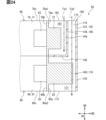
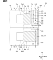
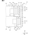
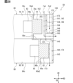
- the cover flow path 160 has a first flow path 161 and a second flow path 171.
- the first flow path 161 and the second flow path 171 are separated by a flow path partitioning portion 144 in the cover flow path 160 .
- a region on the motor fin 72 side with respect to the flow path partition portion 144 is a first flow path 161.
- the region on the inverter fin 92 side with respect to the flow path partition portion 144 is the second flow path 171 .
- a portion of the second flow path 171 is provided outside the first flow path 161 in the radial direction.
- a motor fin 72 is provided in the first flow path 161.
- the first flow path 161 accommodates the motor fin 72.
- the first flow path 161 is a space defined by the motor outer peripheral surface 70a and the flow path partition portion 144.
- the first flow path 161 as a whole extends annularly in the circumferential direction CD.
- the first flow paths 161 are provided at positions aligned in the radial direction RD on the motor outer circumferential surface 70a, but are not provided at positions aligned in the radial direction RD on the inverter outer circumferential surface 90a.
- the first flow path 161 has a first inlet 162, a first outlet 163, a first heat radiation path 164, and a first outlet 166.
- the first inlet 162 is an inlet of the first flow path 161 and is provided at the upstream end of the first flow path 161 .
- the first inlet 162 is open in the axial direction AD.
- the first inlet 162 opens the first flow path 161 toward the blower fan 111 in the axial direction AD.
- the first inlet 162 is provided upstream of the motor fin 72.
- the first inlet 162 extends in the circumferential direction CD along the outer periphery upstream end 70a1.
- the first inlet 162 is formed in an annular shape.
- the first inlet 162 corresponds to a first annular port and a first axial port.
- the first inflow ports 162 are arranged in the motor fin 72 in the axial direction AD.
- the first inlet 162 is located away from the motor fin 72 on the upstream side in the axial direction AD.
- the first outlet 163 is an outlet of the first flow path 161 and is provided at the downstream end of the first flow path 161.
- the first outlet 163 opens the first flow path 161 radially outward.
- the first outflow port 163 is located on the opposite side of the first inflow port 162 via the motor fin 72 in the air flow direction in the first flow path 161 .
- the first outlet 163 is provided on the outer peripheral surface of the outer peripheral cover part 141.
- the first outlet 163 is provided, for example, in the motor cover portion 142.
- a plurality of first outflow ports 163 are arranged in the circumferential direction CD.
- the first outlet 163 is provided between the motor fin 72 and the inverter fin 92 in the axial direction AD.
- at least a portion of the first outlet 163 is provided between the motor fin 72 and the inverter fin 92 in the axial direction AD.
- the first outlet 163 corresponds to an intermediate outlet.
- the first heat radiation path 164 is a space for radiating heat from the motor fins 72 in the first flow path 161.
- the first heat radiation path 164 is a space between the motor outer circumferential surface 70a and the diameter partition portion 146.
- a motor fin 72 is provided in the first heat radiation path 164 .
- the thickness dimension of the first heat radiation path 164 and the protrusion dimension of the motor fin 72 are approximately the same. This is because the motor fin 72 and the diameter partition portion 146 are in contact with each other.
- the first heat radiation path 164 extends in the axial direction AD from the first inlet 162 toward the shaft partition 145.
- the first heat radiation path 164 forms a first inlet 162 .
- the upstream end of the first heat radiation path 164 is the first inlet 162 .
- the first heat radiation path 164 is a space between the motor outer peripheral surface 70a and the flow path partition part 144.
- the first outflow path 166 extends radially outward from the first heat radiation path 164.
- the first outflow path 166 forms the first outflow port 163 .
- the downstream end of the first outflow path 166 is the first outflow port 163 .
- the first outflow passage 166 passes through both the radial partition part 146 and the outer circumferential cover part 141 and is open to the outside in the radial direction.
- the first outflow path 166 extends in the radial direction RD from the first heat radiation path 164 along the shaft partition 145.
- a plurality of first outflow passages 166 are arranged in the circumferential direction CD.
- the fin cover 140 has an outflow forming part 148.
- the outflow forming portion 148 forms a first outflow path 166 .
- the outflow forming portion 148 is formed in a cylindrical shape and extends in the axial direction AD.
- the outflow forming portion 148 connects the flow path partitioning portion 144 and the outer peripheral cover portion 141.
- the inner space of the outflow forming portion 148 serves as a first outflow path 166.
- Outflow formation portion 148 extends along shaft partition portion 145 .
- a plurality of outflow forming portions 148 are arranged in the circumferential direction CD.
- the outflow forming part 148 is formed including a part of the shaft partition part 145. Note that the outflow forming portion 148 may be formed without including the shaft partition portion 145.
- the first outlet 163 is provided at a position offset from the motor fin 72 in the circumferential direction CD.
- the first outlet 163 is located between two motor fin groups 73 adjacent to each other in the circumferential direction CD.
- the first outlet 163 is located away from both of the two motor fin groups 73 adjacent in the circumferential direction CD in the circumferential direction CD.
- the first outlet 163 is located between the shaft partition 145 and the motor fin 72 in the axial direction AD.
- the first outlet 163 is located away from the motor fin 72 in the axial direction AD.
- the first outflow path 166 and the first outflow port 163 are provided at a position offset from the motor fin 72 in the circumferential direction CD. Note that the first outlet 163 may be located at a position overlapping a part of the motor fin 72 in the axial direction AD.
- inverter fins 92 are provided in the second flow path 171. Of the motor fins 72 and the inverter fins 92, only the inverter fins 92 are provided in the second flow path 171.
- the second flow path 171 accommodates the inverter fins 92.
- the second flow path 171 is a space defined by the inverter outer peripheral surface 90a, the flow path partition part 144, and the outer peripheral cover part 141.
- the second flow path 171 extends annularly in the circumferential direction CD as a whole.
- the second flow path 171 extends in the axial direction AD, and spans the diametrical partition portion 146 and the inverter outer peripheral surface 90a.
- a portion of the second flow path 171 is provided outside the first flow path 161 in the radial direction.
- the first flow path 161 is inserted between the second flow path 171 and the motor outer peripheral surface 70a.
- the first flow path 161 and the second flow path 171 are double flow paths arranged in the radial direction RD.
- the second flow path 171 has a second inlet 172, a second outlet 173, a second heat radiation path 174, and a second inflow path 175.
- the second inlet 172 is an inlet of the second flow path 171 and is provided at the upstream end of the second flow path 171 .
- the second inlet 172 is open in the axial direction AD.
- the second inlet 172 opens the second flow path 171 toward the blower fan 111 in the axial direction AD.
- the second inlet 172 is provided upstream of the inverter fins 92.
- the second inlet 172 extends in the circumferential direction CD along the outer periphery upstream end 70a1.
- the second inlet 172 is formed in an annular shape.
- the second inflow port 172 corresponds to a second annular port and a second axial port.
- the second inlet 172 is provided radially outward than the first inlet 162.
- the first inlet 162 is provided between the motor outer peripheral surface 70a and the second inlet 172.
- the first inlet 162 and the second inlet 172 are arranged in the radial direction RD.
- the second inlet 172 is provided at a position away from the inverter fin 92 in each of the axial direction AD and the radial direction RD.
- the second inlet 172 is located radially outwardly away from the inverter fin 92 via the first inlet 162 .
- the second inlet 172 is located away from the inverter fin 92 upstream via the first flow path 161 in the axial direction AD.
- the diametrical partition 146 is provided between the first inlet 162 and the second inlet 172.
- the radial partition portion 146 partitions the second inlet 172 from the second inlet 172 in the radial direction RD.
- the second outlet 173 is an outlet of the second flow path 171 and is provided at the downstream end of the second flow path 171.
- the second outlet 173 opens the second flow path 171 in the axial direction AD toward the side opposite to the blower fan 111 .
- the second outlet 173 is provided downstream of the inverter fins 92.
- the second outlet 173 extends in the circumferential direction CD along the outer peripheral downstream end 90a2.
- the second outlet 173 is formed in an annular shape.
- the second outlet 173 spans the inverter outer peripheral surface 90a and the outer peripheral cover portion 141 in the radial direction RD.
- the second outflow ports 173 are arranged in both the first inflow port 162 and the second inflow port 172 in the axial direction AD. In the radial direction RD, the width dimension of the second outflow port 173 is larger than both the width dimension of the first inflow port 162 and the width dimension of the second inflow port 172.
- the second heat radiation path 174 is a space for radiating heat from the inverter fins 92 in the second flow path 171.
- the second heat radiation path 174 is a space between the inverter outer peripheral surface 90a and the outer peripheral cover part 141.
- Inverter fins 92 are provided in the second heat radiation path 174.
- the thickness dimension of the second heat radiation path 174 is larger than the protrusion dimension of the inverter fin 92. This is because the outer circumferential cover portion 141 is provided at a position radially outwardly away from the radial partition portion 146 by the distance of the second inflow path 175 .
- the second heat radiation path 174 extends in the axial direction AD from the second outlet 173 toward the shaft partition 145.
- the second heat radiation path 174 forms a second outlet 173.
- the downstream end of the second heat radiation path 174 is the second outlet 173 .
- the second heat radiation path 174 is a space between the inverter outer peripheral surface 90a and the inverter cover portion 143.
- the second inflow path 175 extends in the axial direction AD from the second heat radiation path 174 toward the ventilation fan 111.
- the second inflow path 175 forms the second inflow port 172 .
- the upstream end of the second inflow path 175 is the second inflow port 172 .
- the second inflow path 175 is a space between the flow path partition section 144 and the motor cover section 142.
- the second inflow path 175 is provided radially outward from the first heat radiation path 164.
- the second inflow paths 175 are arranged in the first heat radiation path 164 in the radial direction RD.
- the second inflow path 175 is between the first heat radiation path 164 and the motor cover portion 142.
- the second inflow path 175 extends annularly in the circumferential direction CD.
- the first outflow path 166 and the outflow forming portion 148 penetrate the second inflow path 175 in the radial direction RD.
- the fin cover 140 forms a first flow path 161 and a second flow path 171 between the outer peripheral surfaces 70a and 90a.
- the flow path partition portion 144 covers the motor outer peripheral surface 70a so as to form a first flow path 161 between the flow path partition portion 144 and the motor outer peripheral surface 70a.
- the flow path partition part 144 corresponds to a first cover part.
- the outer circumferential cover portion 141 covers the flow path partition portion 144 and the inverter outer peripheral surface 90a so as to form a second flow path 171 between the flow path partition portion 144 and the inverter outer peripheral surface 90a.
- the outer circumferential cover portion 141 corresponds to a second cover portion.
- the first inlet 162 allows air to flow into the first flow path 161 from outside the fin cover 140 without passing through the second flow path 171 .
- the first outlet 163 allows the air in the first flow path 161 to flow out of the fin cover 140 without passing through the second flow path 171 .
- the second inlet 172 allows air to flow into the second flow path 171 from outside the fin cover 140 without passing through the first flow path 161 .
- the second outlet 173 allows the air in the second flow path 171 to flow out of the fin cover 140 without passing through the first flow path 161 .
- the airflow flowing through the cover flow path 160 includes a first airflow Fa1 and a second airflow Fa2.
- the first airflow Fa1 is an airflow flowing through the first flow path 161.
- the first airflow Fa1 flows into the first heat radiation path 164 from the first inlet 162.
- the first airflow Fa1 exchanges heat with the motor fin 72 in the first heat radiation path 164.
- the first airflow Fa1 is heated by the motor fins 72, and then passes through the first outflow path 166 and is emitted to the outside of the fin cover 140 from the first outflow port 163.
- the first airflow Fa1 cools the motor fins 72 by flowing along the motor fins 72 in the first flow path 161.
- the first airflow Fa1 may be referred to as cooling air.
- the first airflow Fa1 tends to flow along the plate surface of the motor fin 72 due to the contact between the radial partition portion 146 and the tip end of the motor fin 72.
- the first airflow Fa1 tends to flow between two motor fins 72 adjacent to each other in the circumferential direction CD. In this way, since the first airflow Fa1 has a large area along which it flows along the motor fins 72, the first airflow Fa1 can easily absorb the heat of the motor fins 72.
- the first airflow Fa1 flows out from each of the plurality of first outlet ports 163 toward the outside in the radial direction.
- the first airflow Fa1 flows out from the first outlet 163 at a position downstream from both the first inlet 162 and the second inlet 172. Therefore, the first airflow Fa1 flowing out from the first outflow port 163 does not flow into the first inflow port 162 and the second inflow port 172 again.
- the second airflow Fa2 is an airflow that flows through the second flow path 171.
- the second airflow Fa2 flows from the second inlet 172 into the second heat radiation path 174 via the second inflow path 175.
- the second airflow Fa2 exchanges heat with the inverter fins 92 in the second heat radiation path 174.
- the second airflow Fa2 is given heat by the inverter fins 92 and is then discharged to the outside of the fin cover 140 from the second outlet 173.
- the second airflow Fa2 cools the inverter fins 92 by flowing along the inverter fins 92 in the second flow path 171.
- the second airflow Fa2 is sometimes referred to as cooling air.
- the first airflow Fa1 flows easily along the plate surface of the motor fin 72 by simply proceeding in the axial direction AD after flowing into the first inflow port 162. Therefore, in the first flow path 161, the heat of the motor fin 72 is easily applied to the first air flow Fa1. Similarly, it is easier for the second airflow Fa2 to flow along the plate surface of the inverter fin 92 by simply proceeding in the axial direction AD after flowing into the second inflow port 172. Therefore, in the second flow path 171, the heat of the inverter fins 92 is easily applied to the second airflow Fa2.
- the second inlet 172 allows the air outside the fin cover 140 to flow into the second flow path 171 as the second air flow Fa2 without passing through the first flow path 161. .
- the second airflow Fa2 that has not absorbed the heat of the motor fins 72 flows into the second flow path 171 from the second inlet 172. Therefore, regarding the second airflow Fa2 flowing into the second flow path 171, the ability to absorb the heat of the inverter fins 92 in the second flow path 171 is lower than that of the second flow path 171, which has already absorbed the heat of the motor fins 72 in the first flow path 161. You can avoid thinking that something is causing the decline.
- the temperature of the second airflow Fa2 is already high due to the heat of the motor fins 72 when the second airflow Fa2 reaches the inverter fins 92. Therefore, the heat dissipation effect of the inverter fins 92 in the second flow path 171 can be enhanced by the second air flow Fa2 that does not pass through the first flow path 161. Thereby, the heat dissipation effect of the EDS 50 and the EDS unit 130 can be enhanced.
- the radial partition part 146 forms the first flow path 161 between the motor outer peripheral surface 70a
- the outer periphery cover part 141 forms the first flow path 161 between the radial partition part 146 and the radial partition part 146.
- a second flow path 171 is formed.
- the first flow path 161 and the second flow path 171 are partitioned in the radial direction RD by the radial partition portion 146. Therefore, the second airflow Fa2 can reach the inverter fins 92 without passing through the first flow path 161 by flowing through the second flow path 171 on the radially outer side of the first flow path 161. Therefore, it is possible to avoid absorbing the heat of the motor outer peripheral wall 71 before the second airflow Fa2 reaches the inverter fins 92.
- the second flow path 171 does not accommodate the motor fin 72 but is formed by the motor outer peripheral surface 70a.
- the second airflow Fa2 does not absorb the heat of the motor fins 72 in the second flow path 171, it may absorb the heat of the motor outer peripheral wall 71 from the motor outer peripheral surface 70a. Therefore, there is a concern that the second airflow Fa2 may absorb heat from the motor outer peripheral wall 71 before reaching the inverter fins 92.
- the first inlet 162 extends annularly in the circumferential direction CD along the motor outer peripheral surface 70a.
- the opening area of the first inlet 162 can be made as large as possible by utilizing the fact that the first inlet 162 has an annular shape. Therefore, the amount of the first airflow Fa1 flowing into the first inlet 162 can be increased as much as possible. In this way, as much of the first airflow Fa1 as possible can flow through the first flow path 161, so that the cooling effect of the motor fins 72 by the first airflow Fa1 can be enhanced.
- the second inlet 172 extends annularly in the circumferential direction CD along the inverter outer peripheral surface 90a.
- the opening area of the second inlet 172 can be made as large as possible by utilizing the fact that the second inlet 172 has an annular shape. Therefore, the amount of second airflow Fa2 flowing into the second inlet 172 can be increased as much as possible. In this way, as much of the second airflow Fa2 as possible can flow through the second flow path 171, so that the cooling effect of the second airflow Fa2 on the inverter fins 92 can be enhanced.
- the second inlet 172 is provided on the radially outer side of the first inlet 162.
- the opening area of the second inflow port 172 is larger than the opening area of the first inflow port 162. big.
- the opening area of the second inlet 172 can be easily increased. Therefore, in addition to the fact that the second airflow Fa2 does not pass through the first flow path 161, the flow rate of the second airflow Fa2 flowing through the second flow path 171 tends to increase, thereby increasing the cooling effect of the inverter fin group 93. I can do it.
- the first inlet 162 and the second inlet 172 are open in the axial direction AD. Therefore, it is possible to realize a configuration in which the first airflow Fa1 flowing in the axial direction AD easily flows into the first inflow port 162, and the second airflow Fa2 easily flows into the second inflow port 172. Moreover, in the configuration in which the second flow path 171 is provided on the radially outer side of the first flow path 161, by opening both the first inlet 162 and the second inlet 172 in the axial direction AD, the first flow The configuration for arranging the inlet 162 and the second inlet 172 in the radial direction RD can be simplified.
- the first outlet 163 is provided between the motor fin 72 and the inverter fin 92 in the axial direction AD.
- the first flow path 161 it is not necessary for the first flow path 161 to extend in the axial direction AD to the position of the inverter fin 92. Therefore, at the position where the inverter fin 92 is provided, the second flow path 171 can be arranged so as to extend throughout the circumferential direction CD. Therefore, the second airflow Fa2 flowing through the second flow path 171 can cool the entire inverter outer peripheral wall 91 and inverter fins 92 in the circumferential direction CD.
- the motor fin group 73 and the inverter fin group 93 are arranged in the axial direction AD, and the first outlet 163 is located at a position offset from the motor fin group 73 in the circumferential direction CD.
- the first outlet 163 is located at a position offset from the motor fin group 73 in the circumferential direction CD.
- the rotor 20 rotates around the rotation axis Cm. With this configuration, it becomes easy to form the cover flow path 160 so that the air flowing due to the rotation of the rotor 20 flows into the cover flow path 160.
- the rotor 20 rotates so that air flows through the first flow path 161 and the second flow path 171.
- both the air flowing due to the rotation of the blower fan 111 and the air flowing due to the rotation of the rotor 20 flow through the first flow path 161 and the second flow path 171. Therefore, the amount of air flowing through the cover flow path 160 tends to increase. Therefore, the heat radiation effect of the motor fins 72 and the inverter fins 92 can be enhanced by the rotor 20.
- the first outlet 163 is provided at a position offset from the motor fin group 73 in the circumferential direction CD.
- the first outlet 163 is not displaced from the motor fin group 73 in the circumferential direction CD. Configurations, operations, and effects that are not particularly described in the second embodiment are the same as those in the first embodiment. The second embodiment will be explained mainly on points different from the first embodiment.
- the first outlet 163 is not separated from the motor fin group 73 in the circumferential direction CD.
- the first outlet 163 is provided in the motor fin group 73 at a position aligned in the axial direction AD. That is, the first outlet 163 is located in line with the motor fin 72 in the axial direction AD. Therefore, the first outlet 163 is not separated from the motor fin 72 in the circumferential direction CD, nor is it displaced from the motor fin 72 in the circumferential direction CD.
- the first outlet 163 is arranged near the center of the motor fin group 73 in the circumferential direction CD.
- the motor fin 72 is located between the first inlet 162 and the first outlet 163. That is, the motor fin group 73 is located between the first inlet 162 and the first outlet 163.
- the first airflow Fa1 flowing in from the first inlet 162 reaches the first outlet 163 after flowing along the motor fins 72. Therefore, the first airflow Fa1 easily absorbs the heat of the motor fins 72 before flowing out from the first outlet 163. In other words, it is possible to suppress the first airflow Fa1 flowing in from the first inlet 162 from flowing out from the first outlet 163 without absorbing the heat of the motor fins 72 . Therefore, the cooling effect of the motor fins 72 by the first airflow Fa1 can be enhanced.
- the EDS 50 had one motor device 60 and one inverter device 80.
- the EDS 50 includes a plurality of motor devices 60 and a plurality of inverter devices 80. Configurations, operations, and effects that are not particularly described in the third embodiment are the same as those in the first embodiment. The third embodiment will be mainly described with respect to the points that are different from the first embodiment.
- the EDS 50 has two motor devices 60 and two inverter devices 80. That is, the EDS 50 has two motor housings 70 and two inverter housings 90.
- the two motor devices 60 and the two inverter devices 80 are stacked in the axial direction AD. In the axial direction AD, two motor devices 60 are arranged next to each other, and two inverter devices 80 are arranged next to each other. This is one boundary between the motor device 60 and the inverter device 80.
- the fin cover 140 covers all of the two motor devices 60 and the two inverter devices 80 from the outer peripheral side.
- the motor fin groups 73 of the two motor devices 60 are arranged in the axial direction AD.
- the inverter fins 92 of the two inverter devices 80 are arranged in the axial direction AD.
- the motor fin group 73 of the motor device 60 and the inverter fin group 93 of the inverter device 80 are arranged in the axial direction AD.
- the diameter partition portion 146 covers the two motor devices 60 from the outer peripheral side.
- a shaft partition 145 and a first outlet 163 are provided at the boundary between the motor device 60 and the inverter device 80 that are adjacent to each other in the axial direction AD. Similar to the first embodiment, at least a portion of the first outlet 163 is provided between the motor fin 72 and the inverter fin 92 in the axial direction AD.
- the first airflow Fa1 flows along each of the two motor fins 72 arranged in the axial direction AD in the first flow path 161, and then flows out from the first outlet 163.
- the second airflow Fa2 flows along each of the two inverter fins 92 arranged in the axial direction AD in the second flow path 171, and then flows out from the second outlet 173.
- the EDS 50 has three housings such as a motor housing 70.
- the three housings are arranged in the axial direction AD.
- the EDS 50 includes two motor devices 60 and one inverter device 80.
- the two motor devices 60 are arranged in the axial direction AD via one inverter device 80.
- the two motor fins 72 are arranged in the axial direction AD via one inverter fin 92. That is, the two motor fin groups 73 are arranged in the axial direction AD via one inverter fin group 93.
- the outer circumferential cover portion 141 covers the two motor devices 60 and one inverter device 80 from the outside in the radial direction.
- the outer circumferential cover portion 141 extends in the axial direction AD so as to span the two motor devices 60 via one inverter device 80.
- the outer circumferential cover portion 141 extends across two inverter fins 92 via one inverter fin 92 in the axial direction AD.
- the outer circumferential cover part 141 includes an upstream motor fin 72 provided on the side of the blower fan 111, an inverter fin 92, and a downstream motor fin 72 provided on the opposite side of the blower fan 111 via the inverter fin 92. and is covered from the outside in the radial direction.
- the outer circumference cover part 141 has a first motor cover part 142a and a second motor cover part 142b as the motor cover part 142.
- the first motor cover part 142a and the second motor cover part 142b are arranged in the axial direction AD with the inverter cover part 143 in between.
- the first motor cover portion 142a covers the upstream motor fin 72 from the outer peripheral side.
- the second motor cover portion 142b covers the motor fin 72 on the downstream side from the outer peripheral side.
- the flow path partition section 144 has a first shaft partition section 145a and a second shaft partition section 145b as the shaft partition section 145.
- the first shaft partition part 145a and the second shaft partition part 145b are arranged in the axial direction AD.
- the first shaft partition 145a is provided between the motor fin 72 and the inverter fin 92 on the upstream side.
- the second shaft partition portion 145b is provided between the inverter fin 92 and the motor fin 72 on the downstream side.
- the flow path partitioning section 144 has a first radial partitioning section 146a and a second radial partitioning section 146b as the radial partitioning section 146.
- the first radial partition portion 146a and the second radial partition portion 146b are arranged in the radial direction RD.
- the first radial partition portion 146a covers the upstream motor fin 72 from the outside in the radial direction.
- the second radial partition portion 146b extends between the first radial partition portion 146a and the inverter fin 92 in the axial direction AD.
- the second radial partition 146b covers the first radial partition 146a and the inverter fin 92 from the outside in the radial direction.
- the second radial partition 146b covers the upstream motor fin 72 from the outside in the radial direction via the first radial partition 146a.
- the outer circumferential cover portion 141 spans the second radial partition portion 146b and the motor fin 72 on the downstream side in the axial direction AD.
- the outer circumferential cover portion 141 covers the second radial partition portion 146b and the downstream motor fin 72 from the outside in the radial direction.
- the outer circumferential cover portion 141 covers the inverter fin 92 from the outside in the radial direction via the second radial partition portion 146b.
- the outer circumferential cover portion 141 covers the motor fin 72 from the outside in the radial direction via the first radial partition portion 146a and the second radial partition portion 146b.
- the cover flow path 160 has a third flow path 181 in addition to the first flow path 161 and the second flow path 171.
- the first flow path 161 is provided with an upstream motor fin 72 .
- Inverter fins 92 are provided in the second flow path 171 .
- the third flow path 181 is provided with a motor fin 72 on the downstream side.
- the first flow path 161, the second flow path 171, and the third flow path 181 as a whole extend annularly in the circumferential direction CD.
- a part of the second flow path 171 is provided on the radially outer side of the first flow path 161.
- a portion of the third flow path 181 is provided outside the first flow path 161 and the second flow path 171 in the radial direction.
- the first flow path 161 is provided between the upstream motor fin 72 and the second flow path 171.
- the second flow path 171 is provided between the first flow path 161 and the third flow path 181.
- the first flow path 161 and the second flow path 171 are partitioned by a first axial partition 145a and a first radial partition 146a.
- the second flow path 171 and the third flow path 181 are partitioned by a second shaft partition 145b and a second radial partition 146b.
- the first flow path 161 includes a first inlet 162, a first outlet 163, a first heat radiation path 164, and a first outflow path 166, as in the first embodiment. have.
- the second flow path 171 has a second outlet 173A as the second outlet 173.
- the second flow path 171 includes a second inflow port 172, a second outflow port 173A, a second heat radiation path 174, a second inflow path 175, and a second outflow path 176.
- the third flow path 181 has a third inlet 182, a third outlet 183, and a third heat radiation path 184.
- the fin cover 140 has a first outflow forming part 148a and a second outflow forming part 148b as the outflow forming part 148.
- the upstream motor fin 72 is provided in the first heat radiation path 164.
- the inverter fins 92 are provided in the second heat radiation path 174.
- the motor fin 72 on the downstream side is provided in the third heat radiation path 184.
- the first heat radiation path 164, the second heat radiation path 174, and the third heat radiation path 184 are arranged in the axial direction AD. These heat radiation paths 164, 174, and 184 extend annularly in the circumferential direction CD.
- the first heat radiation path 164 is formed between the upstream motor outer peripheral surface 70a and the first radial partition portion 146a.
- the second heat radiation path 174 is formed between the inverter outer peripheral surface 90a and the second radial partition portion 146b.
- the third heat radiation path 184 is formed between the motor outer peripheral surface 70a and the outer peripheral cover part 141 on the downstream side.
- the first outflow path 166 penetrates the first radial partition portion 146a and the second radial partition portion 146b and is open to the outside in the radial direction.
- the first flow path 161 is formed by the first outflow forming portion 148a.
- the first outflow forming portion 148a is in a state spanning the first radial partition portion 146a, the first radial partition portion 146a, and the outer circumferential cover portion 141 in the radial direction RD.
- the first flow path 161 and the first outflow forming portion 148a penetrate the second inflow path 175 and the third inflow path 185 in the radial direction RD.
- a plurality of first outflow ports 163, first outflow paths 166, and first outflow forming portions 148a are arranged in the circumferential direction CD.
- the second outlet 173A is provided in the outer cover portion 141, unlike the second outlet 173 of the first embodiment.
- the second outlet 173A opens the second flow path 171 radially outward.
- the second outlet 173A is provided in the inverter cover section 143 of the outer circumferential cover section 141.
- a plurality of second outlet ports 173A are arranged in the circumferential direction CD.
- the second outlet 173A is provided between the motor fin 72 and the inverter fin 92 on the upstream side in the axial direction AD.
- at least a portion of the second outlet 173A is provided between the motor fin 72 and the inverter fin 92 on the upstream side in the axial direction AD.
- the second outlet 173A corresponds to an intermediate outlet.
- the second outflow path 176 extends radially outward from the second heat radiation path 174.
- the second outflow path 176 forms a second outflow port 173A.
- the second outflow path 176 penetrates both the flow path partition part 144 and the outer peripheral cover part 141 and is open to the outside in the radial direction.
- the second outflow path 176 is formed by the second outflow forming portion 148b.
- the second outflow forming portion 148b is in a state spanning the second radial partition portion 146b and the outer circumferential cover portion 141 in the radial direction RD.
- the second flow path 171 and the second outflow forming portion 148b penetrate the third inflow path 185 in the radial direction RD.
- a plurality of second outflow ports 173A, second outflow paths 176, and second outflow forming portions 148b are arranged in the circumferential direction CD.
- the third flow path 181 has the same configuration as the second flow path 171 in that it covers the other flow paths from the outside in the radial direction.
- the second flow path 171 covers the first flow path 161 from the outside in the radial direction
- the third flow path 181 covers the second flow path 171 from the outside in the radial direction.
- the third inlet 182, like the first inlet 162 and the second inlet 172, is open in the axial direction AD and extends annularly in the circumferential direction CD.
- the third inflow path 185 extends from the third heat radiation path 184 in the axial direction AD, and forms the third inflow port 182.
- the third outlet 183 is open in the axial direction AD and extends annularly in the circumferential direction CD, similarly to the second outlet 173 of the first embodiment.
- the airflow flowing through the cover channel 160 includes a third airflow Fa3 in addition to the first airflow Fa1 and the second airflow Fa2.
- the third airflow Fa3 is an airflow flowing through the third flow path 181.
- the third airflow Fa3 flows into the third heat radiation path 184 from the third inlet 182.
- the third airflow Fa3 exchanges heat with the motor fin 72 on the downstream side in the third heat radiation path 184.
- the third airflow Fa3 is given heat from the motor fins 72 on the downstream side, and then is discharged to the outside of the fin cover 140 from the third outlet 183.
- the third airflow Fa3 cools the motor fins 72 on the downstream side by flowing along the motor fins 72 on the downstream side in the third flow path 181.
- the third airflow Fa3 is sometimes referred to as cooling air.
- the outer circumferential cover portion 141 extends in the axial direction AD parallel to the motor outer circumferential surface 70a and the inverter outer circumferential surface 90a.
- the outer circumferential cover portion 141 is inclined with respect to the motor outer circumferential surface 70a and the inverter outer circumferential surface 90a. Configurations, operations, and effects that are not particularly described in the fifth embodiment are the same as those in the first embodiment. The fifth embodiment will be described with a focus on points that are different from the first embodiment.
- the outer circumferential cover portion 141 is inclined so that the outer circumferential surface of the outer circumferential cover portion 141 faces the side opposite to the blower fan 111.
- the distance between the outer circumferential cover portion 141 and the motor outer circumferential surface 70a in the radial direction RD gradually becomes smaller toward the side opposite to the blower fan 111 in the axial direction AD.
- the distance between the outer circumferential cover portion 141 and the inverter outer circumferential surface 90a in the radial direction RD gradually becomes smaller toward the side opposite to the blower fan 111 in the axial direction AD.
- the radial partition portion 146 extends in the axial direction AD parallel to the motor outer circumferential surface 70a.
- the overall thickness of the second flow path 171 in the radial direction RD gradually decreases toward the downstream side.
- the cross-sectional area of the cross section perpendicular to the axial direction AD in the second flow path 171 gradually decreases toward the downstream side.
- the thickness of the second inlet passage 175 in the radial direction RD gradually becomes smaller toward the second outlet port 173 in the axial direction AD.
- the thickness of the second heat radiation path 174 in the radial direction RD gradually becomes smaller toward the second outlet 173 in the axial direction AD.
- the second airflow Fa2 flows toward the second outflow port 173 along the inner circumferential surface of the outer circumferential cover portion 141 after flowing into the second inflow port 172.
- the second airflow Fa2 is guided radially inward by the outer cover portion 141 so as to approach the inverter fins 92 in the second heat radiation path 174. Therefore, the second airflow Fa2 easily passes between the two inverter fins 92 adjacent to each other in the circumferential direction CD. That is, the second airflow Fa2 easily flows along the plate surface of the inverter fin 92.
- the motor fins 72 and the inverter fins 92 have the same length in the radial direction RD.
- the length of the inverter fin 92 is larger than the length of the motor fin 72 in the radial direction RD. Configurations, operations, and effects that are not particularly described in the sixth embodiment are the same as those in the first embodiment. The sixth embodiment will be described with a focus on points that are different from the first embodiment.
- the protrusion dimension of the inverter fins 92 from the inverter outer peripheral surface 90a is larger than the protrusion dimension of the motor fins 72 from the motor outer peripheral surface 70a.
- the inverter fins 92 protrude more radially outward than the radial partition portion 146 in the radial direction RD.
- the tip portion of the inverter fin 92 is located between the radial partition portion 146 and the outer circumferential cover portion 141 in the radial direction RD.
- the tip portion of the inverter fin 92 is located in line with the second inlet 172 in the axial direction AD.
- the tip of the inverter fin 92 is in contact with the outer cover portion 141.
- the outer circumferential cover portion 141 is pressed against the inverter fins 92 by the restoring force of the fin cover 140.
- the fin cover 140 is held in position with respect to the motor housing 70 and the inverter housing 90 because the outer circumferential cover portion 141 is pressed against the inverter fins 92 .
- the positional relationship between the inverter fins 92 and the outer circumferential cover part 141 is the same as the positional relationship between the motor fins 72 and the radial partition part 146.
- the inverter fins 92 and the outer circumferential cover part 141 may be apart in the radial direction RD.
- the distance between the inverter fins 92 and the outer circumferential cover portion 141 in the radial direction RD may be approximately the same as the distance between the motor fins 72 and the radial partition portion 146.
- the second airflow Fa2 flows into the second inlet 172 and then simply flows in the axial direction AD along the outer circumferential cover portion 141 to reach the tip of the inverter fin 92. It's getting easier. This is because the inverter fins 92 are lined up at the second inlet 172 and the second inflow path 175 in the axial direction AD. Therefore, after the second airflow Fa2 flows into the second heat radiation path 174 from the second inflow path 175, it easily reaches the inverter fins 92 even if it does not flow radially inward. In this way, even if the second airflow Fa2 simply flows in the axial direction AD along the outer circumferential cover portion 141, it easily flows along the plate surface of the inverter fin 92.
- the motor outer peripheral surface 70a and the inverter outer peripheral surface 90a are arranged in the axial direction AD.
- the inverter outer circumferential surface 90a is provided radially outward than the motor outer circumferential surface 70a. Configurations, operations, and effects that are not particularly described in the seventh embodiment are the same as those in the first embodiment. The seventh embodiment will be described with a focus on points that are different from the first embodiment.
- the inverter housing 90 protrudes further radially outward than the motor housing 70.
- the inverter outer circumferential wall 91 protrudes more radially outward than the motor outer circumferential wall 71.
- the inverter outer circumferential surface 90a is provided at a position radially outwardly away from the motor outer circumferential surface 70a.
- the inverter fins 92 are provided at a position apart from the motor outer circumferential surface 70a in the radial direction along with the inverter outer circumferential surface 90a.
- the inverter fins 92 protrude further radially outward than the motor fins 72 by the amount that the inverter outer circumferential surface 90a protrudes radially outward from the motor outer circumferential surface 70a.
- the tip portion of the inverter fin 92 is located between the radial partition portion 146 and the outer circumferential cover portion 141 in the radial direction RD, similarly to the sixth embodiment.
- the inverter outer circumferential surface 90a is spaced radially outward from the motor outer circumferential surface 70a to such an extent that the tips of the inverter fins 92 contact the outer circumferential cover part 141.
- the second airflow Fa2 easily flows along the plate surface of the inverter fin 92 even if it simply flows in the axial direction AD along the outer circumferential cover portion 141.
- the second heat radiation path 174 is thinner in the radial direction RD by the amount that the inverter outer peripheral surface 90a protrudes radially outward from the motor outer peripheral surface 70a.
- the inverter outer peripheral surface 90a is disposed at a position close to the outer peripheral cover portion 141 toward the outside in the radial direction. Therefore, the second airflow Fa2 flows easily along the inverter outer peripheral surface 90a after flowing into the second heat radiation path 174 from the second inflow path 175. Therefore, the second airflow Fa2 easily absorbs the heat of the inverter outer peripheral wall 91 from the inverter outer peripheral surface 90a.
- the first heat radiation path 164 and the second heat radiation path 174 are arranged in the axial direction AD.
- the second heat radiation path 174 is provided at a position radially outwardly away from the first heat radiation path 164. Configurations, operations, and effects not particularly described in the eighth embodiment are the same as those in the first embodiment. The eighth embodiment will be described with a focus on points that are different from the first embodiment.
- the inverter outer peripheral wall 91 is provided at a position aligned with the radial partition portion 146 in the axial direction AD.
- the inverter outer circumferential surface 90a is arranged on the outer circumferential surface of the radial partition portion 146 in the axial direction AD.
- the inverter outer circumferential surface 90a is provided radially outward than the motor outer circumferential surface 70a.
- Inverter housing 90 protrudes radially outward from first heat radiation path 164 .
- the upstream inverter end face 90c defines a first heat radiation path 164.
- the thickness of the second inflow path 175 and the thickness of the second heat radiation path 174 are approximately the same in the radial direction RD. Further, the second inflow path 175 and the second heat radiation path 174 are arranged in the axial direction AD. In the second flow path 171, the thickness dimension in the radial direction RD is uniform in the axial direction AD. Therefore, the second airflow Fa2 that has entered the second inlet 172 simply flows through the second inflow path 175 and the second heat radiation path 174, thereby making it easier to flow along the plate surface of the inverter fin 92.
- the second flow path 171 has a second inlet 172A as a second inlet 172.
- the second inlet 172A is different from the second inlet 172 of the first embodiment, and is provided in the outer cover portion 141.
- the second inlet 172A opens the second flow path 171 radially outward.
- the second inlet 172A is provided in the inverter cover section 143 of the outer circumferential cover section 141.
- a plurality of second inflow ports 172A are arranged in the circumferential direction CD.
- the second inlet 172A is provided between the motor fin 72 and the inverter fin 92 in the axial direction AD.
- at least a portion of the second inlet 172A is provided between the motor fin 72 and the inverter fin 92 in the axial direction AD.
- the second inflow port 172A corresponds to a second cover port.
- the shaft partition 145 is provided between the first heat radiation path 164 and the second heat radiation path 174, as in the first embodiment. and the second heat radiation path 174 in the axial direction AD.
- the diameter partition portion 146 is provided between the inverter fin 92 and the outer circumferential cover portion 141, unlike the first embodiment.
- the radial partition portion 146 covers the inverter fin 92 from the outside in the radial direction.
- the diameter partition portion 146 may or may not be in contact with the tip of the inverter fin 92.
- the first outflow path 166 extends in the axial direction AD from the first heat radiation path 164 toward the downstream side.
- the first outflow path 166 has a first outflow port 163A as the first outflow port 163.
- the first outflow port 163A opens the first outflow path 166 in the axial direction AD toward the downstream side.
- the first outlet 163A is provided on the radially outer side of the second outlet 173.
- the first outlet 163A extends in the radial direction RD along the second outlet 173.
- the first outlet 163A is formed in an annular shape.
- the second inlet 172A is the inlet of the second inflow path 175.
- the second inflow path 175 extends radially outward from the second heat radiation path 174.
- the second inflow path 175 penetrates both the radial partition portion 146 and the outer circumferential cover portion 141 and is open to the outside in the radial direction.
- the second inflow path 175 extends in the radial direction RD from the second heat radiation path 174 along the shaft partition 145.
- a plurality of second inflow passages 175 are arranged in the circumferential direction CD.
- the fin cover 140 has an inflow forming portion 149.
- the inflow forming portion 149 forms a second inflow path 175 and a second inflow port 172A.
- the inflow forming portion 149 is formed in a cylindrical shape and extends in the axial direction AD.
- the inflow forming portion 149 connects the flow path partitioning portion 144 and the outer peripheral cover portion 141.
- the internal space of the inflow forming portion 149 serves as a second inflow path 175 .
- the inflow formation portion 149 extends along the shaft partition portion 145 .
- the inflow formation part 149 is formed including a part of the shaft partition part 145.
- a plurality of inflow forming portions 149 are arranged in the circumferential direction CD. Note that the inflow forming portion 149 may be formed without including the shaft partition portion 145.
- the EDS unit 130 includes a blower fan 111A as the blower fan 111.
- the blower fan 111A is provided downstream of the EDS 50.
- a blower device 110 having a blower fan 111A is provided downstream of the EDS 50.
- the blower fan 111A sends air in the axial direction AD toward the side opposite to the EDS 50.
- the blower fan 111A causes external air to flow into the first inlet 162 by causing air to flow out from the first outlet 163A so as to suck out the air in the first flow path 161.
- the blower fan 111A causes external air to flow into the second outlet 173 by causing air to flow out from the second outlet 173 so as to suck out the air in the second flow path 171.
- the blower fan 111A corresponds to a downstream fan.
- the first airflow Fa1 and the second airflow Fa2 flow as the blower fan 111A is driven.
- the first airflow Fa1 flows into the first inflow port 162 as it flows out from the first outflow port 163A.
- the second airflow Fa2 flows in from the second inflow port 172A as it flows out from the second outflow port 173.
- the second inlet 172A is provided between the motor fin 72 and the inverter fin 92 in the axial direction AD.
- the blower fan 111A is provided downstream of the second outlet 173.
- the second airflow Fa2 flows so as to be sucked out from the second outflow port 173 by the air blowing from the ventilation fan 111A, so that the second airflow Fa2 can be caused to flow in from the second inflow port 172A. Therefore, even if the second inlet 172A is opened radially outward, it is possible to realize a configuration in which the second airflow Fa2 flows into the second inlet 172A.
- the fin cover 140 had the flow path partition part 144.
- the fin cover 140 does not have the channel partition part 144.
- the configuration, operation, and effects not particularly described in the tenth embodiment are the same as those in the ninth embodiment.
- the tenth embodiment will be described with a focus on the points that are different from the ninth embodiment.
- the fin cover 140 does not partition the first flow path 161 and the second flow path 171.
- the cover flow path 160 is not provided with the flow path partition portion 144 .
- the first flow path 161 and the second flow path 171 are arranged in the axial direction AD and form a continuous space.
- the space that accommodates the motor fins 72 is the first channel 161
- the space that accommodates the inverter fins 92 is the second channel 171.
- the boundary between the first flow path 161 and the second flow path 171 is aligned in the radial direction RD at the boundary between the motor outer circumferential surface 70a and the inverter outer circumferential surface 90a.
- the first outlet 163 is included in the boundary between the first flow path 161 and the second flow path 171.
- the second flow path 171 has a second inlet 172B as the second inlet 172.
- the second inlet 172B is provided in the outer circumferential cover portion 141 similarly to the second inlet 172A of the ninth embodiment.
- a plurality of second inflow ports 172B are arranged in the circumferential direction CD.
- the second inlet 172B is provided between the motor fin 72 and the inverter fin 92 in the axial direction AD.
- at least a portion of the second inlet 172B is provided between the motor fin 72 and the inverter fin 92 in the axial direction AD.
- the second inflow port 172B corresponds to a second cover port and a second common port.
- the outer circumferential cover portion 141 is provided with a through hole that forms a second inlet 172B.
- This through hole penetrates the outer circumferential cover portion 141 in the radial direction RD.
- This through hole forms a second inflow path 175 in addition to the second inflow port 172B.
- the inner space of this through hole is the second inflow path 175.
- the portion where this through hole is formed is also the inflow forming portion 149 that forms the second inflow path 175.
- a blower fan 111A is provided downstream of the EDS 50, as in the ninth embodiment.
- the blower fan 111A causes external air to flow into the second inlet 172B by causing air to flow out from the second outlet 173 so as to suck out the air in the second flow path 171. Further, the blower fan 111A causes external air to flow into the first inlet 162 by causing air to flow out from the second outlet 173 so as to suck out the air in the second flow path 171.
- the first airflow Fa1 and the second airflow Fa2 flow as the blower fan 111A is driven.
- the second airflow Fa2 flows into the second inflow port 172B as it flows out from the second outflow port 173.
- the first airflow Fa1 flows into the first inflow port 162 as the second airflow Fa2 flows out from the second outflow port 173.
- the first airflow Fa1 that has flowed into the first inlet 162 flows out from the first flow path 161 via the second flow path 171 and from the second outlet 173 to the outside.
- the second airflow Fa2 flows into the second flow path 171 from the second inflow port 172B, and then flows into the inverter fin 92 while merging with the first flow path 161 that has flowed into the second flow path 171 from the first flow path 161. flows along.
- the second inlet 172B is provided between the motor fin 72 and the inverter fin 92 in the axial direction AD.
- a configuration in which the second inlet 172B is provided downstream of the motor fin 72 can be realized. Therefore, it is possible to reliably prevent the second airflow Fa2 flowing into the second inlet 172B from absorbing the heat of the motor fins 72.
- the blower fan 111A is provided downstream of the second outlet 173, as in the ninth embodiment.
- the second airflow Fa2 flows so as to be sucked out from the second outflow port 173 by the air blowing from the blower fan 111A, so that the second airflow Fa2 can be caused to flow in from the second inflow port 172B. Therefore, even if the second inlet 172B is opened radially outward, it is possible to realize a configuration in which the second airflow Fa2 flows into the second inlet 172B.
- the second inlet 172B is arranged in the axial direction AD in the outer circumferential cover portion 141 so that the second airflow Fa2 flows along the inverter fins 92 while joining the first airflow Fa1. between the motor fins 72 and the inverter fins 92.
- the second air flow Fa2 that does not pass through the first flow path 161 increases the heat dissipation effect of the inverter fins 92 in the second flow path 171 by simply providing the second inlet 172B in the outer peripheral cover portion 141. This can be achieved with a simple configuration.
- the first flow path 161 and the second flow path 171 are partitioned in the radial direction RD.
- the first flow path 161 and the second flow path 171 are partitioned in the circumferential direction CD. Configurations, operations, and effects that are not particularly described in the eleventh embodiment are the same as those in the first embodiment. The eleventh embodiment will be described with a focus on points that are different from the first embodiment.
- the motor fins 72 and the inverter fins 92 are provided at positions shifted in the circumferential direction CD. That is, the motor fin group 73 and the inverter fin group 93 are at positions shifted in the circumferential direction CD. For example, a region between two motor fin groups 73 adjacent in the circumferential direction CD is located in a position aligned with the inverter fin group 93 in the axial direction AD. Similarly, a region between two inverter fin groups 93 adjacent in the circumferential direction CD is located in line with the motor fin group 73 in the axial direction AD.
- the first flow path 161 and the second flow path 171 are arranged in the circumferential direction CD.
- a plurality of the first flow passages 161 and the second flow passages 171 are arranged in plurality in the circumferential direction CD.
- the first flow passages 161 and the second flow passages 171 are alternately arranged one by one in the circumferential direction CD.
- the first inlet 162 and the second inlet 172 are arranged in the circumferential direction CD.
- the first outlet 163 and the second outlet 173 are arranged in the circumferential direction CD.
- the first heat radiation path 164 and the second inflow path 175 are lined up in the circumferential direction CD.
- the second inflow path 175 is provided between two adjacent motor fin groups 73 in the circumferential direction CD.
- the second heat radiation path 174 and the first outflow path 166 are lined up in the circumferential direction CD.
- the first outflow path 166 is provided between two inverter fin groups 93 adjacent to each other in the circumferential direction CD.
- the first heat radiation path 164 and the second heat radiation path 174 are adjacent to each other in at least one of the axial direction AD and the circumferential direction CD.
- the width dimension of the first heat radiation path 164 is larger than the width dimension of the first outflow path 166.
- the width of the second heat radiation path 174 is larger than the width of the second inflow path 175.
- a portion of the first heat radiation path 164 is located in line with the second heat radiation path 174 in the axial direction AD.
- a portion of the second heat radiation path 174 is located in line with the first heat radiation path 164 in the axial direction AD.
- the flow path partition section 144 has a peripheral partition section 147.
- the circumferential partition portion 147 is provided between the first flow path 161 and the second flow path 171 in the cover flow path 160.
- the circumferential partition portion 147 partitions the first flow path 161 and the second flow path 171 in the circumferential direction CD between the motor outer circumferential surface 70a, the inverter outer circumferential surface 90a, and the outer circumferential cover portion 141.
- the outer circumferential cover portion 141 covers the motor outer circumferential surface 70a and the inverter outer circumferential surface 90a so as to form both the first flow path 161 and the second flow path 171.
- the outer circumferential cover portion 141 corresponds to a circumferential extension portion.
- the first airflow Fa1 and the second airflow Fa2 basically flow in the axial direction AD.
- the first airflow Fa1 that has flowed into the first inflow port 162 absorbs the heat of the motor fin 72 in the first heat radiation path 164, and then flows out from the first outflow port 163 through the first outflow path 166.
- the second airflow Fa2 that has flowed into the second inflow port 172 passes through the second inflow path 175, reaches the second heat radiation path 174, absorbs the heat of the inverter fins 92 in the second heat radiation path 174, and then enters the second airflow It flows out from the outlet 173.
- the outer circumferential cover portion 141 is in contact with both the motor fins 72 and the inverter fins 92.
- the outer circumferential cover portion 141 is pressed against both the motor fins 72 and the inverter fins 92 due to the restoring force of the fin cover 140.
- the first airflow Fa1 easily flows along the plate surface of the motor fin 72
- the second airflow Fa2 easily flows along the plate surface of the inverter fin 92.
- the circumferential partition portion 147 partitions the first flow path 161 and the second flow path 171 such that the first flow path 161 and the second flow path 171 are lined up in the circumferential direction CD. .
- the first flow path 161 and the second flow path 171 overlap in the radial direction RD. Therefore, as in the first embodiment, the second air flow Fa2 that does not pass through the first flow path 161 enhances the heat dissipation effect of the inverter fins 92 in the second flow path 171, and the fin cover 140 has a diameter Enlargement in the direction RD can be suppressed.
- the first outlet 163 is open in the axial direction AD. In contrast, in the twelfth embodiment, the first outlet 163 is open radially outward. Configurations, operations, and effects that are not particularly described in the twelfth embodiment are the same as those in the eleventh embodiment. The twelfth embodiment will be described with a focus on points that are different from the eleventh embodiment.
- the first outlet 163 is provided in the outer cover portion 141 similarly to the first embodiment.
- the first outlet 163 opens the first heat radiation path 164 to the outside in the radial direction.
- the first outlet 163 is provided between the motor fin 72 and the inverter fin 92 in the axial direction AD.
- the first outlet 163 is provided at a position straddling the boundary between the motor outer circumferential surface 70a and the inverter outer circumferential surface 90a in the axial direction AD.
- the first outlet 163 may be located closer to the motor fin 72 than the boundary between the motor outer peripheral surface 70a and the inverter outer peripheral surface 90a, or may be located closer to the inverter fin 92.
- a through hole forming a first outlet 163 is provided in the outer circumferential cover portion 141 .
- This through hole penetrates the outer circumferential cover portion 141 in the radial direction RD, and forms a first outflow passage 166 in addition to the first outflow port 163 .
- the space inside this through hole is the first outflow path 166.
- the part where this through hole is formed is also the outflow forming part 148 which forms the first outflow path 166.
- the first outflow path 166 is not provided in a position aligned with the second heat radiation path 174 in the circumferential direction CD. That is, the first outflow path 166 does not extend in the axial direction AD from the first heat radiation path 164 toward the downstream side along the inverter outer peripheral surface 90a. In the axial direction AD, the entire region downstream of the first heat radiation path 164 is the second heat radiation path 174 .
- the second heat radiation path 174 may be divided into a plurality of parts in the circumferential direction CD. For example, a dividing portion that divides the second heat radiation path 174 in the circumferential direction CD may be provided between two inverter fin groups 93 adjacent in the circumferential direction CD.
- the flow path partitioning section 144 has a shaft partitioning section 145 in addition to a circumferential partitioning section 147.
- the shaft partition 145 connects two adjacent circumferential partitions 147 via the motor fin group 73 in the circumferential direction CD.
- the shaft partition portion 145 partitions the first heat radiation path 164 and the second heat radiation path 174 between the motor fin 72 and the inverter fin 92 in the axial direction AD.
- the first outflow path 166 does not traverse the inverter outer peripheral surface 90a in the axial direction AD.
- the range in which the second airflow Fa2 flows along the inverter outer circumferential surface 90a can be made as wide as possible. Therefore, a wide range of the inverter outer circumferential surface 90a can be cooled by the second airflow Fa2 that does not absorb the heat of the motor fins 72.
- the first flow path 161 and the second flow path 171 are partitioned in the circumferential direction CD.
- the first flow path 161 and the second flow path 171 are partitioned in the axial direction AD. Configurations, operations, and effects that are not particularly described in the thirteenth embodiment are the same as those in the twelfth embodiment. The thirteenth embodiment will be described with a focus on points different from the twelfth embodiment.
- the first flow path 161 and the second flow path 171 are arranged in the axial direction AD.
- the first flow path 161 and the second flow path 171 extend annularly in the circumferential direction CD.
- the first flow path 161 is provided upstream of the second flow path 171 in the axial direction AD.
- the first inlet 162 is open in the axial direction AD, while the first outlet 163 is open radially outward.
- the first outflow port 163 is provided in the outer circumferential cover portion 141 similarly to the twelfth embodiment.
- the outer circumferential cover portion 141 corresponds to an axially extending portion.
- the second outlet 173 is open in the axial direction AD, while the second inlet 172 is open radially outward.
- the second inlet 172 is provided in the outer cover portion 141 similarly to the first outlet 163 .
- the second inlet 172 opens the second heat radiation path 174 to the outside in the radial direction.
- the second inlet 172 is provided between the motor fin 72 and the inverter fin 92 in the axial direction AD.
- the second inlet 172 is provided at a position that straddles the boundary between the motor outer circumferential surface 70a and the inverter outer circumferential surface 90a in the axial direction AD.
- the second inlet 172 may be located closer to the motor fin 72 than the boundary between the motor outer peripheral surface 70a and the inverter outer peripheral surface 90a, or may be located closer to the inverter fin 92.
- a through hole forming a second inlet 172 is provided in the outer circumferential cover portion 141 .
- This through hole penetrates the outer circumferential cover portion 141 in the radial direction RD, and forms a second inflow path 175 in addition to the second inflow port 172 .
- the inner space of this through hole is the second inflow path 175.
- the portion where this through hole is formed is also the inflow forming portion 149 that forms the second inflow path 175.
- the flow path partition part 144 has a shaft partition part 145 but does not have a circumferential partition part 147.
- the shaft partition portion 145 is provided between the first heat radiation path 164 and the second heat radiation path 174 in the axial direction AD.
- the shaft partition portion 145 extends in the circumferential direction CD and partitions the first heat radiation path 164 and the second heat radiation path 174 in the axial direction AD.
- the first outflow ports 163 and the second inflow ports 172 are arranged alternately in the circumferential direction CD. At least a portion of the second inlet 172 is provided upstream of the first outlet 163 in the axial direction AD.
- the first outlet 163 is provided closer to the motor fin 72 than the flow path partition 144 .
- the second inlet 172 is provided closer to the inverter fin 92 than the flow path partition 144 .
- the first heat radiation path 164 may be divided into a plurality of parts in the circumferential direction CD.
- a dividing portion that divides the first heat radiation path 164 in the circumferential direction CD may be provided between two motor fin groups 73 adjacent in the circumferential direction CD.
- a blowing fan 111 is provided on each of the upstream and downstream sides of the EDS 50.
- a blower fan 111 as an upstream fan is provided on the upstream side of the EDS 50
- a blower fan 111A as a downstream fan is provided on the downstream side of the EDS50.
- the blower fan 111 as an upstream fan forces the first airflow Fa1 into the first inflow port 162, and causes the first airflow Fa1 to flow out from the first outflow port 163.
- the blower fan 111A as a downstream fan causes the second airflow Fa2 to flow into the first inflow port 162 by sucking out the second airflow Fa2 from the second outflow port 173.
- the cover flow path 160 At least a part of the first outlet 163 through which the first airflow Fa1 flows out is provided upstream of the second inlet 172 into which the second airflow Fa2 flows. Moreover, the first outflow port 163 and the second inflow port 172 are provided at positions separated from each other in the circumferential direction CD. Therefore, it is difficult for the first airflow Fa1 flowing out from the first outflow port 163 to flow into the second inflow port 172. Therefore, it is possible to suppress the fact that the first airflow Fa1 is mixed with the second airflow Fa2 flowing into the second inlet 172 and the temperature of the second airflow Fa2 increases.
- the axial partition part 145 partitions the first flow path 161 and the second flow path 171 so that the first flow path 161 and the second flow path 171 are lined up in the axial direction AD. .
- the first flow path 161 and the second flow path 171 there is no need for the first flow path 161 and the second flow path 171 to overlap in the radial direction RD. Therefore, as in the eleventh embodiment, the second air flow Fa2 that does not pass through the first flow path 161 enhances the heat dissipation effect of the inverter fins 92 in the second flow path 171, and the fin cover 140 has a diameter Enlargement in the direction RD can be suppressed.
- the motor fins 72 may be provided in any manner on the motor outer peripheral surface 70a as long as they can release heat from the motor outer peripheral wall 71, such as the heat of the stator 63, to the outside.
- the inverter fins 92 may be provided in any manner on the inverter outer peripheral surface 90a as long as the heat from the inverter outer peripheral wall 91, such as the heat of the switch module 83, can be released to the outside.
- the motor fins 72 and the inverter fins 92 may extend in a direction inclined in the circumferential direction CD with respect to the rotation axis Cm.
- the motor housing 70 may be provided downstream of the inverter housing 90.
- the motor housing 70 may be provided between the inverter housing 90 and the blower fan 111 in the axial direction AD.
- the motor device 60 may be provided between the blower fan 111 and the inverter device 80 in the axial direction AD, and the inverter device 80 may be provided between the blower fan 111 and the motor device 60.
- the motor device 60 and the inverter device 80 may have a common housing.
- the motor 61 and the drive unit 81 may be housed in one housing. Further, both the motor 61 and the drive section 81 may not be housed in the housing of the EDS 50. This housing only needs to house heat generating elements such as the motor 61 and the drive unit 81.
- the heating element may be embedded in the housing as long as it is accommodated in the housing.
- the switch module 83 may be embedded in the inverter outer peripheral wall 91.
- the switch module 83 is provided in the inverter housing 90 between the inverter outer peripheral surface 90a and the inverter inner peripheral surface 90b.
- the rotor axis does not need to coincide with the rotation axis Cm. That is, the rotation center of the rotor 20 may not be the rotation axis Cm.
- the rotor axis may be located away from the rotation axis Cm in the radial direction RD, or may be inclined with respect to the rotation axis Cm.
- the airflow flowing through the cover flow path 160 may be an airflow generated by rotation of at least the rotor 20 and the blower fan 111.
- the air flowing due to the rotation of the rotor 20 does not need to flow through the cover flow path 160.
- the drive device unit such as the EDS unit 130 may be a unit that includes a drive device such as the EDS 50 and a fan such as the ventilation fan 111.
- the drive unit may include only the blower fan 111 out of the blower fan 111 and the shroud 120.
- the drive device unit may include a rotor 20 in addition to the drive device and the fan.
- the fin cover 140 may be fixed to a housing such as the motor housing 70 using a fixing device such as a bolt. Fin cover 140 does not need to be elastically deformable.
- the fin cover 140 may be located at a position spaced radially outward from the heat radiation fins such as the motor fins 72.
- the shroud 120 may be fixed to the fin cover 140.
- the fin cover 140 and the shroud 120 may be integrally formed.
- the eVTOL 10 does not need to be a tilt rotor machine. That is, in the eVTOL 10, the rotor 20 does not need to be tiltable.
- the plurality of rotors 20 may include a lift rotor 20 and a cruise rotor 20, respectively. In this eVTOL 10, for example, the lift rotor 20 is driven when moving up, and the cruise rotor 20 is driven when moving forward.
- the aircraft on which the EDS 50 and the EDS unit 130 are mounted does not have to be a vertical takeoff and landing aircraft.
- the aircraft may be a rotary wing aircraft or a fixed wing aircraft.
- the rotor corresponds to the rotor.
- the propeller is equivalent to the rotor.
- the flying object may be an unmanned aircraft without a person on board.
- AD axial direction
- a first flow path (161) in which the upstream fins are provided and a second flow path (171) in which the downstream fins are provided are formed between the outer peripheral surface, and gas flows through the first flow path. and a housing cover (140) that covers the outer peripheral surface so as to flow through the second flow path; a first inlet (162) that is included in the first flow path and allows gas to flow into the first flow path from outside the housing cover without passing through the second flow path; a second inlet (172, 172A, 172B) that is included in the second flow path and allows gas to flow into the second flow path from outside the housing cover without passing through the first flow path; A drive device equipped with.
- the housing cover is a first cover part (145) that covers the outer peripheral surface so as to form the first flow path between the first cover part (145) and the outer peripheral surface; a second cover part (141) that covers the first cover part so as to form the second flow path between the second cover part and the first cover part;
- the drive device according to Technical Idea 1 which has the following.
- Technical thought 4 a first axial port (162) that is open in the axial direction as the first inlet; a second axial port (172), which is provided as the second inflow port on the outer peripheral side of the first inflow port via the first cover part and is open in the axial direction;
- the drive device according to Technical Idea 2 or 3 comprising:
- At least a portion of the second cover part is provided between the upstream fin and the downstream fin in the axial direction, is included in the first flow path, and is configured to conduct gas from the first flow path to the second flow path.
- the drive device according to any one of technical ideas 2 to 4, further comprising an intermediate outlet (163) for allowing the flow to flow out of the housing cover without passing through a channel.
- the second inlet includes a second cover port (172A, 172B) at least partially provided between the upstream fin and the downstream fin in the axial direction in the second cover part.
- the drive device according to any one of technical ideas 2 to 5.
- the housing cover is a circumferentially extending portion (141) that covers the outer circumferential surface so as to form the first flow path and the second flow path between the outer circumferential surface;
- the first flow path and the second flow path are provided between the outer circumferential surface and the circumferential extension part, and the first flow path and the second flow path are arranged in a circumferential direction (CD) of the rotation axis.
- a peripheral partition part (147) that partitions the flow path;
- the housing cover is an axially extending portion (141) that covers the outer peripheral surface so as to form the first flow path and the second flow path between the outer peripheral surface; provided between the outer peripheral surface and the axially extending portion, partitioning the first flow path and the second flow path so that the first flow path and the second flow path are aligned in the axial direction; a shaft partition (145),
- the drive device according to any one of Technical Ideas 1 to 7, which has the following.
- the second inlet is configured such that the gas that has flown in from the first inlet and flows along the downstream fins while merging with the gas that has passed through the first flow path.
- the drive according to any one of technical ideas 1 to 8, further comprising a second common port (172B) at least partially provided between the upstream fin and the downstream fin in the axial direction. Device.
- the fan is provided on the downstream side of the second outflow port, and is configured to direct gas so that the gas flows from the outside of the housing cover into the second common port as the gas flows out from the second outflow port.
- a downstream fan (111A) that flows comprising:
- the upstream fin is provided at a position aligned with the first inlet in the axial direction
- the drive device according to any one of technical ideas 1 to 10, wherein the downstream fin is provided at a position aligned with the second inlet in the axial direction.
- AD axial direction
- a first flow path (161) in which the upstream fins are provided and a second flow path (171) in which the downstream fins are provided are formed between the outer peripheral surface, and gas flows through the first flow path. and a housing cover (140) that covers the outer peripheral surface so as to flow through the second flow path; a first inlet (162) that is included in the first flow path and allows gas to flow into the first flow path from outside the housing cover without passing through the second flow path; a second inlet (172, 172A, 172B) that is included in the second flow path and allows gas to flow into the second flow path from outside the housing cover without passing through the first flow path;
- a drive unit having:
Landscapes
- Engineering & Computer Science (AREA)
- Power Engineering (AREA)
- Mechanical Engineering (AREA)
- Aviation & Aerospace Engineering (AREA)
- Chemical & Material Sciences (AREA)
- Combustion & Propulsion (AREA)
- Physics & Mathematics (AREA)
- Thermal Sciences (AREA)
- Remote Sensing (AREA)
- Motor Or Generator Cooling System (AREA)
- Motor Or Generator Frames (AREA)
Priority Applications (3)
| Application Number | Priority Date | Filing Date | Title |
|---|---|---|---|
| EP23796062.0A EP4518112A4 (de) | 2022-04-28 | 2023-04-10 | Antriebsvorrichtung und antriebsvorrichtungseinheit |
| CN202380035771.1A CN119137841A (zh) | 2022-04-28 | 2023-04-10 | 驱动装置和驱动装置单元 |
| US18/799,535 US20240405633A1 (en) | 2022-04-28 | 2024-08-09 | Driving device and driving device unit |
Applications Claiming Priority (2)
| Application Number | Priority Date | Filing Date | Title |
|---|---|---|---|
| JP2022075079A JP7729249B2 (ja) | 2022-04-28 | 2022-04-28 | 駆動装置 |
| JP2022-075079 | 2022-04-28 |
Related Child Applications (1)
| Application Number | Title | Priority Date | Filing Date |
|---|---|---|---|
| US18/799,535 Continuation US20240405633A1 (en) | 2022-04-28 | 2024-08-09 | Driving device and driving device unit |
Publications (1)
| Publication Number | Publication Date |
|---|---|
| WO2023210316A1 true WO2023210316A1 (ja) | 2023-11-02 |
Family
ID=88518383
Family Applications (1)
| Application Number | Title | Priority Date | Filing Date |
|---|---|---|---|
| PCT/JP2023/014485 Ceased WO2023210316A1 (ja) | 2022-04-28 | 2023-04-10 | 駆動装置及び駆動装置ユニット |
Country Status (5)
| Country | Link |
|---|---|
| US (1) | US20240405633A1 (de) |
| EP (1) | EP4518112A4 (de) |
| JP (1) | JP7729249B2 (de) |
| CN (1) | CN119137841A (de) |
| WO (1) | WO2023210316A1 (de) |
Families Citing this family (2)
| Publication number | Priority date | Publication date | Assignee | Title |
|---|---|---|---|---|
| CN119483063B (zh) * | 2024-11-04 | 2025-10-24 | 珠海格力电器股份有限公司 | 电机端盖、工业用电机 |
| JP7780161B1 (ja) | 2025-03-24 | 2025-12-04 | 国立研究開発法人宇宙航空研究開発機構 | 熱交換器および航空機 |
Citations (4)
| Publication number | Priority date | Publication date | Assignee | Title |
|---|---|---|---|---|
| JPH0993865A (ja) * | 1995-09-29 | 1997-04-04 | Hitachi Ltd | 誘導電動機 |
| US7367385B1 (en) * | 1999-09-28 | 2008-05-06 | Materna Peter A | Optimized fins for convective heat transfer |
| US20150180311A1 (en) * | 2013-12-20 | 2015-06-25 | Industrial Technology Research Institute | Motor controller with cooling function and cooling method for cooling a motor controller |
| KR20180051270A (ko) * | 2016-11-08 | 2018-05-16 | 한국항공우주연구원 | 모터 냉각 장치 |
Family Cites Families (4)
| Publication number | Priority date | Publication date | Assignee | Title |
|---|---|---|---|---|
| JP6361336B2 (ja) | 2014-07-10 | 2018-07-25 | 富士電機株式会社 | 電力変換装置一体型電動機 |
| JP6794441B2 (ja) * | 2016-06-01 | 2020-12-02 | 株式会社日立製作所 | モータ装置 |
| CN207759049U (zh) * | 2017-12-22 | 2018-08-24 | 江苏优埃唯智能科技有限公司 | 一种无人机的散热装置 |
| CN214241252U (zh) * | 2020-12-23 | 2021-09-21 | 卧龙电气驱动集团股份有限公司 | 一种飞行器电力推进器散热系统 |
-
2022
- 2022-04-28 JP JP2022075079A patent/JP7729249B2/ja active Active
-
2023
- 2023-04-10 CN CN202380035771.1A patent/CN119137841A/zh not_active Withdrawn
- 2023-04-10 WO PCT/JP2023/014485 patent/WO2023210316A1/ja not_active Ceased
- 2023-04-10 EP EP23796062.0A patent/EP4518112A4/de active Pending
-
2024
- 2024-08-09 US US18/799,535 patent/US20240405633A1/en active Pending
Patent Citations (4)
| Publication number | Priority date | Publication date | Assignee | Title |
|---|---|---|---|---|
| JPH0993865A (ja) * | 1995-09-29 | 1997-04-04 | Hitachi Ltd | 誘導電動機 |
| US7367385B1 (en) * | 1999-09-28 | 2008-05-06 | Materna Peter A | Optimized fins for convective heat transfer |
| US20150180311A1 (en) * | 2013-12-20 | 2015-06-25 | Industrial Technology Research Institute | Motor controller with cooling function and cooling method for cooling a motor controller |
| KR20180051270A (ko) * | 2016-11-08 | 2018-05-16 | 한국항공우주연구원 | 모터 냉각 장치 |
Non-Patent Citations (1)
| Title |
|---|
| See also references of EP4518112A4 * |
Also Published As
| Publication number | Publication date |
|---|---|
| EP4518112A4 (de) | 2025-08-06 |
| US20240405633A1 (en) | 2024-12-05 |
| JP7729249B2 (ja) | 2025-08-26 |
| CN119137841A (zh) | 2024-12-13 |
| EP4518112A1 (de) | 2025-03-05 |
| JP2023163874A (ja) | 2023-11-10 |
Similar Documents
| Publication | Publication Date | Title |
|---|---|---|
| US20240213855A1 (en) | Drive device and drive device unit | |
| CA3028159C (en) | Heat dissipation system for electric aircraft engine | |
| US20240405633A1 (en) | Driving device and driving device unit | |
| US10608505B1 (en) | Cooling motor controller with a motor with duct | |
| US20250096646A1 (en) | Drive device | |
| WO2024004402A1 (ja) | 推進装置 | |
| JP2024004442A (ja) | 推進装置 | |
| US20240208662A1 (en) | Drive device and drive device unit | |
| US20250105703A1 (en) | Drive device | |
| JP7521558B2 (ja) | 駆動装置及び駆動装置ユニット | |
| EP3291419B1 (de) | Elektrische rotationsmaschine | |
| JP7484975B2 (ja) | 駆動装置及び駆動装置ユニット | |
| EP4653327A1 (de) | Antriebsvorrichtung | |
| US20250373119A1 (en) | Rotary electric machine | |
| WO2024048342A1 (ja) | 駆動装置 | |
| CN118103294A (zh) | 驱动装置和驱动装置单元 | |
| US20200389074A1 (en) | Air pulser for motor vehicle | |
| WO2025047559A1 (ja) | 駆動装置 | |
| US20250202306A1 (en) | Rotary electric machine | |
| JP2024101529A (ja) | 推進装置 | |
| WO2025258348A1 (ja) | モータ制御装置および電動推進ユニット | |
| WO2025187487A1 (ja) | インバータ装置 | |
| WO2025169716A1 (ja) | 電動推進ユニット | |
| WO2026079259A1 (ja) | ロータおよびモータ | |
| CN121012233A (zh) | 一种轴向磁通电机的散热结构、轴向磁通电机和飞行器 |
Legal Events
| Date | Code | Title | Description |
|---|---|---|---|
| 121 | Ep: the epo has been informed by wipo that ep was designated in this application |
Ref document number: 23796062 Country of ref document: EP Kind code of ref document: A1 |
|
| WWE | Wipo information: entry into national phase |
Ref document number: 202380035771.1 Country of ref document: CN |
|
| WWE | Wipo information: entry into national phase |
Ref document number: 2023796062 Country of ref document: EP |
|
| NENP | Non-entry into the national phase |
Ref country code: DE |
|
| ENP | Entry into the national phase |
Ref document number: 2023796062 Country of ref document: EP Effective date: 20241128 |