WO2023210316A1 - Drive device and drive device unit - Google Patents
Drive device and drive device unit Download PDFInfo
- Publication number
- WO2023210316A1 WO2023210316A1 PCT/JP2023/014485 JP2023014485W WO2023210316A1 WO 2023210316 A1 WO2023210316 A1 WO 2023210316A1 JP 2023014485 W JP2023014485 W JP 2023014485W WO 2023210316 A1 WO2023210316 A1 WO 2023210316A1
- Authority
- WO
- WIPO (PCT)
- Prior art keywords
- flow path
- motor
- inverter
- fin
- cover
- Prior art date
Links
- 230000002093 peripheral effect Effects 0.000 claims description 206
- 238000005192 partition Methods 0.000 claims description 148
- 238000011144 upstream manufacturing Methods 0.000 claims description 79
- 238000000638 solvent extraction Methods 0.000 claims description 17
- 230000005855 radiation Effects 0.000 description 108
- 230000000694 effects Effects 0.000 description 29
- RZVHIXYEVGDQDX-UHFFFAOYSA-N 9,10-anthraquinone Chemical compound C1=CC=C2C(=O)C3=CC=CC=C3C(=O)C2=C1 RZVHIXYEVGDQDX-UHFFFAOYSA-N 0.000 description 18
- 238000001816 cooling Methods 0.000 description 12
- 230000017525 heat dissipation Effects 0.000 description 12
- 238000007664 blowing Methods 0.000 description 9
- 238000002149 energy-dispersive X-ray emission spectroscopy Methods 0.000 description 8
- 230000001419 dependent effect Effects 0.000 description 4
- 230000006870 function Effects 0.000 description 4
- 239000011347 resin Substances 0.000 description 4
- 229920005989 resin Polymers 0.000 description 4
- 238000009423 ventilation Methods 0.000 description 4
- 230000015572 biosynthetic process Effects 0.000 description 3
- 238000004891 communication Methods 0.000 description 3
- 230000007423 decrease Effects 0.000 description 3
- 238000001514 detection method Methods 0.000 description 3
- 239000000463 material Substances 0.000 description 3
- 230000000191 radiation effect Effects 0.000 description 3
- 239000004065 semiconductor Substances 0.000 description 3
- 238000006243 chemical reaction Methods 0.000 description 2
- 238000010586 diagram Methods 0.000 description 2
- 230000005489 elastic deformation Effects 0.000 description 2
- 238000010438 heat treatment Methods 0.000 description 2
- HBBGRARXTFLTSG-UHFFFAOYSA-N Lithium ion Chemical compound [Li+] HBBGRARXTFLTSG-UHFFFAOYSA-N 0.000 description 1
- PXHVJJICTQNCMI-UHFFFAOYSA-N Nickel Chemical compound [Ni] PXHVJJICTQNCMI-UHFFFAOYSA-N 0.000 description 1
- 239000000853 adhesive Substances 0.000 description 1
- 230000001070 adhesive effect Effects 0.000 description 1
- 230000008859 change Effects 0.000 description 1
- 239000003638 chemical reducing agent Substances 0.000 description 1
- 230000005669 field effect Effects 0.000 description 1
- 239000000446 fuel Substances 0.000 description 1
- 230000006698 induction Effects 0.000 description 1
- 229910001416 lithium ion Inorganic materials 0.000 description 1
- 239000007769 metal material Substances 0.000 description 1
- 238000000034 method Methods 0.000 description 1
- 238000012986 modification Methods 0.000 description 1
- 230000004048 modification Effects 0.000 description 1
- 229910000652 nickel hydride Inorganic materials 0.000 description 1
- 230000008569 process Effects 0.000 description 1
- 230000004044 response Effects 0.000 description 1
- 238000006467 substitution reaction Methods 0.000 description 1
Images


Classifications
-
- H—ELECTRICITY
- H02—GENERATION; CONVERSION OR DISTRIBUTION OF ELECTRIC POWER
- H02K—DYNAMO-ELECTRIC MACHINES
- H02K9/00—Arrangements for cooling or ventilating
- H02K9/02—Arrangements for cooling or ventilating by ambient air flowing through the machine
-
- H—ELECTRICITY
- H02—GENERATION; CONVERSION OR DISTRIBUTION OF ELECTRIC POWER
- H02K—DYNAMO-ELECTRIC MACHINES
- H02K9/00—Arrangements for cooling or ventilating
- H02K9/02—Arrangements for cooling or ventilating by ambient air flowing through the machine
- H02K9/04—Arrangements for cooling or ventilating by ambient air flowing through the machine having means for generating a flow of cooling medium
- H02K9/06—Arrangements for cooling or ventilating by ambient air flowing through the machine having means for generating a flow of cooling medium with fans or impellers driven by the machine shaft
Landscapes
- Engineering & Computer Science (AREA)
- Power Engineering (AREA)
- Motor Or Generator Cooling System (AREA)
- Motor Or Generator Frames (AREA)
Abstract
A motor housing (70) is provided with motor fins (72) on a motor outer circumferential surface (70a). An inverter housing (90) is provided with inverter fins (92) on an inverter outer circumferential surface (90a). A fin cover (140) covers the motor fins (72) and the inverter fins (92) from the outside in the radial direction. A cover flow path (160) is formed between the fin cover (140) and the motor outer circumferential surface (70a) and between the fin cover (140) and the inverter outer circumferential surface (90a). The cover flow path (160) has a first flow path (161) provided with the motor fins (72) and a second flow path (171) provided with the inverter fins (92). In the second flow path (171), a second airflow (Fa2) that flows in a second flow inlet port (172) reaches the inverter fins (92) not via the first flow path (161).
Description
この出願は、2022年4月28日に日本に出願された特許出願第2022-075079号を基礎としており、基礎の出願の内容を、全体的に、参照により援用している。
This application is based on Patent Application No. 2022-075079 filed in Japan on April 28, 2022, and the content of the underlying application is incorporated by reference in its entirety.
この明細書における開示は、駆動装置及び駆動装置ユニットに関する。
The disclosure in this specification relates to a drive device and a drive device unit.
特許文献1には、航空機に搭載される電子モジュールが開示されている。この電子モジュールは、航空機に搭載された推進装置を駆動する駆動装置である。電子モジュールは、インバータ及びケースを有している。ケースは、筒状部及び放熱フィンを有している。筒状部は、軸方向に延びており、インバータを収容している。放熱フィンは、筒状部の外面に設けられている。放熱フィンは、軸方向に複数並べられている。
Patent Document 1 discloses an electronic module mounted on an aircraft. This electronic module is a drive device that drives a propulsion device mounted on an aircraft. The electronic module has an inverter and a case. The case has a cylindrical portion and heat radiation fins. The cylindrical portion extends in the axial direction and houses the inverter. The radiation fins are provided on the outer surface of the cylindrical part. A plurality of heat radiation fins are arranged in the axial direction.
上記特許文献1では、電子モジュールにおいて、空気等の気体が冷却気流として軸方向に流れると、放熱フィンの放熱効果が冷却気流により高くなりやすい。しかしながら、上記特許文献1では、複数の放熱フィンが軸方向に並んでいる。このため、下流側の放熱フィンは、上流側の放熱フィンとの熱交換を行い温度上昇した冷却気流と熱交換を行うことになる。したがって、冷却空気による放熱効果は、下流側の放熱フィンの方が上流側のフィンに比べて低くなりやすい。
In Patent Document 1, in an electronic module, when gas such as air flows in the axial direction as a cooling airflow, the heat radiation effect of the radiation fins tends to be higher due to the cooling airflow. However, in Patent Document 1, a plurality of radiation fins are arranged in the axial direction. Therefore, the heat radiation fins on the downstream side exchange heat with the heat radiation fins on the upstream side and the cooling air flow whose temperature has increased. Therefore, the heat dissipation effect of the cooling air tends to be lower in the downstream side radiation fins than in the upstream side fins.
本開示の主な目的は、放熱効果を高めることができる駆動装置及び駆動装置ユニットを提供することである。
The main objective of the present disclosure is to provide a drive device and a drive device unit that can enhance the heat dissipation effect.
この明細書に開示された複数の態様は、それぞれの目的を達成するために、互いに異なる技術的手段を採用する。また、請求の範囲及びこの項に記載した括弧内の符号は、一つの態様として後述する実施形態に記載の具体的手段との対応関係を示す一例であって、技術的範囲を限定するものではない。
The multiple embodiments disclosed in this specification employ different technical means to achieve their respective objectives. Furthermore, the symbols in parentheses described in the claims and this section are examples showing correspondence with specific means described in the embodiments described later as one aspect, and do not limit the technical scope. do not have.
上記目的を達成するため、開示された態様は、
飛行体のロータを回転させるために駆動する駆動装置であって、
ロータを回転させるための駆動により発熱する発熱部と、
気体を流すファンの回転軸線に沿って延びた外周面を有し、発熱部を収容したハウジングと、
外周面に設けられ、発熱部からの熱を気体に放出する上流フィンと、
外周面において、回転軸線の軸方向での気体の流れに対して上流フィンよりも下流側に設けられ、発熱部からの熱を気体に放出する下流フィンと、
上流フィンが設けられた第1流路と、下流フィンが設けられた第2流路と、を外周面との間に形成し、気体が第1流路及び第2流路を流れるように外周面を覆っているハウジングカバーと、
第1流路に含まれ、気体をハウジングカバーの外部から第2流路を経由させずに第1流路に流入させる第1流入口と、
第2流路に含まれ、気体をハウジングカバーの外部から第1流路を経由させずに第2流路に流入させる第2流入口と、
を備えている駆動装置である。 To achieve the above objectives, the disclosed aspects include:
A drive device for rotating a rotor of a flying object,
A heat generating part that generates heat due to the drive to rotate the rotor;
A housing having an outer peripheral surface extending along the rotational axis of a fan that flows gas and housing a heat generating part;
an upstream fin that is provided on the outer peripheral surface and releases heat from the heat generating part to gas;
A downstream fin that is provided on the outer circumferential surface on the downstream side of the upstream fin with respect to the gas flow in the axial direction of the rotation axis, and that releases heat from the heat generating part to the gas;
A first channel in which an upstream fin is provided and a second channel in which a downstream fin is provided are formed between the outer peripheral surface, and the outer periphery is arranged so that the gas flows through the first channel and the second channel. a housing cover covering the surface;
a first inlet that is included in the first flow path and allows gas to flow into the first flow path from outside the housing cover without passing through the second flow path;
a second inlet that is included in the second flow path and allows gas to flow into the second flow path from outside the housing cover without passing through the first flow path;
This is a drive device equipped with.
上記態様によれば、第2流入口は、ハウジングカバーの外部の気体を第1流路を経由しないように第2流路に流入させる。この構成では、上流フィンの熱を吸収していない気体が、第2流入口から第2流路に流入する。このため、第2流路に流入した気体について、第2流路で下流フィンの熱を吸収する能力が、すでに第1流路で上流フィンの熱を吸収済みであることで低下している、ということを回避できる。したがって、第1流路を経由していない気体により第2流路での下流フィンの放熱効果を高めることができる。これにより、駆動装置の放熱効果を高めることができる。
According to the above aspect, the second inlet port allows the gas outside the housing cover to flow into the second flow path without passing through the first flow path. In this configuration, gas that has not absorbed heat from the upstream fins flows into the second flow path from the second inlet. For this reason, the ability of the gas flowing into the second flow path to absorb the heat of the downstream fins in the second flow path is reduced because the heat of the upstream fins has already been absorbed in the first flow path. This can be avoided. Therefore, the heat dissipation effect of the downstream fins in the second flow path can be enhanced by the gas that has not passed through the first flow path. Thereby, the heat dissipation effect of the drive device can be enhanced.
開示された態様は、
飛行体に搭載される駆動装置ユニットであって、
飛行体のロータを回転させるために駆動する駆動装置と、
回転軸線を中心に回転して気体を送り、回転軸線に沿って駆動装置に並べられたファンと、
を備え、
駆動装置は、
ロータを回転させるための駆動により発熱する発熱部と、
回転軸線に沿って延びた外周面を有し、発熱部を収容したハウジングと、
外周面に設けられ、発熱部からの熱を気体に放出する上流フィンと、
外周面において、回転軸線の軸方向での気体の流れに対して上流フィンよりも下流側に設けられ、発熱部からの熱を気体に放出する下流フィンと、
上流フィンが設けられた第1流路と、下流フィンが設けられた第2流路と、を外周面との間に形成し、気体が第1流路及び第2流路を流れるように外周面を覆っているハウジングカバーと、
第1流路に含まれ、気体をハウジングカバーの外部から第2流路を経由させずに第1流路に流入させる第1流入口と、
第2流路に含まれ、気体をハウジングカバーの外部から第1流路を経由させずに第2流路に流入させる第2流入口と、
を有している駆動装置ユニットである。 The disclosed aspects include:
A drive unit mounted on a flying object,
a drive device that drives a rotor of the aircraft to rotate;
A fan that rotates around a rotation axis to send gas and is arranged in a drive device along the rotation axis;
Equipped with
The drive device is
A heat generating part that generates heat due to the drive to rotate the rotor;
a housing having an outer circumferential surface extending along the rotational axis and housing a heat generating part;
an upstream fin that is provided on the outer peripheral surface and releases heat from the heat generating part to gas;
A downstream fin that is provided on the outer circumferential surface on the downstream side of the upstream fin with respect to the gas flow in the axial direction of the rotation axis, and that releases heat from the heat generating part to the gas;
A first channel in which an upstream fin is provided and a second channel in which a downstream fin is provided are formed between the outer peripheral surface, and the outer periphery is arranged so that the gas flows through the first channel and the second channel. a housing cover covering the surface;
a first inlet that is included in the first flow path and allows gas to flow into the first flow path from outside the housing cover without passing through the second flow path;
a second inlet that is included in the second flow path and allows gas to flow into the second flow path from outside the housing cover without passing through the first flow path;
This is a drive device unit having a.
上記駆動装置ユニットによれば、上記駆動装置と同様の効果を奏することができる。したがって、駆動装置ユニットの放熱効果を高めることができる。
According to the above drive device unit, the same effects as the above drive device can be achieved. Therefore, the heat dissipation effect of the drive device unit can be enhanced.
以下に、図面を参照しながら本開示を実施するための複数の形態を説明する。各形態において先行する形態で説明した事項に対応する部分には同一の参照符号を付して重複する説明を省略する場合がある。各形態において構成の一部のみを説明している場合は、構成の他の部分については先行して説明した他の形態を適用することができる。各実施形態で具体的に組み合わせが可能であることを明示している部分同士の組み合わせばかりではなく、特に組み合わせに支障が生じなければ、明示していなくても実施形態同士を部分的に組み合せることも可能である。
Hereinafter, multiple embodiments for carrying out the present disclosure will be described with reference to the drawings. In each form, parts corresponding to matters explained in the preceding form may be given the same reference numerals and redundant explanation may be omitted. When only a part of the configuration is described in each form, the other forms previously described can be applied to other parts of the structure. Not only combinations of parts that specifically indicate that combinations are possible in each embodiment, but also partial combinations of embodiments even if it is not explicitly stated, as long as there is no particular problem with the combination. It is also possible.
<第1実施形態>
図1に示す駆動システム30は、eVTOL10に搭載されている。eVTOL10は、電動垂直離着陸機であり、垂直方向に離着陸することが可能である。eVTOLは、electric Vertical Take-Off and Landing aircraftの略称である。eVTOL10は、大気中を飛行する航空機であり、飛行体に相当する。eVTOL10は、電動式の航空機でもあり、電動航空機と称されることがある。eVTOL10は、乗員が乗る有人航空機である。駆動システム30は、eVTOL10を飛行させるために駆動するシステムである。 <First embodiment>
Thedrive system 30 shown in FIG. 1 is installed in the eVTOL 10. The eVTOL 10 is an electric vertical takeoff and landing aircraft, and is capable of vertical takeoff and landing. eVTOL is an abbreviation for electric Vertical Take-Off and Landing aircraft. The eVTOL 10 is an aircraft that flies in the atmosphere and corresponds to a flying object. The eVTOL 10 is also an electric aircraft and is sometimes referred to as an electric aircraft. The eVTOL 10 is a manned aircraft on which a crew member rides. The drive system 30 is a system that drives the eVTOL 10 to fly.
図1に示す駆動システム30は、eVTOL10に搭載されている。eVTOL10は、電動垂直離着陸機であり、垂直方向に離着陸することが可能である。eVTOLは、electric Vertical Take-Off and Landing aircraftの略称である。eVTOL10は、大気中を飛行する航空機であり、飛行体に相当する。eVTOL10は、電動式の航空機でもあり、電動航空機と称されることがある。eVTOL10は、乗員が乗る有人航空機である。駆動システム30は、eVTOL10を飛行させるために駆動するシステムである。 <First embodiment>
The
eVTOL10は、機体11及びロータ20を有している。機体11は、機体本体12及び翼13を有している。機体本体12は、機体11の胴体であり、例えば前後に延びた形状になっている。機体本体12は、乗員が乗るための乗員室を有している。翼13は、機体本体12から延びており、機体本体12に複数設けられている。翼13は固定翼である。複数の翼13には、主翼、尾翼などが含まれている。
The eVTOL 10 has a body 11 and a rotor 20. The fuselage 11 has a fuselage main body 12 and wings 13. The fuselage main body 12 is the fuselage of the fuselage 11, and has a shape that extends from front to back, for example. The fuselage main body 12 has a crew compartment for a crew member to ride. The wings 13 extend from the fuselage main body 12, and a plurality of wings 13 are provided in the fuselage main body 12. Wing 13 is a fixed wing. The plurality of wings 13 include a main wing, a tail wing, and the like.
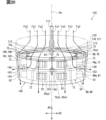
図1、図3に示すロータ20は、機体11に複数設けられている。ロータ20は、機体本体12及び翼13のそれぞれに設けられている。ロータ20は、ロータ軸線を中心に回転する。ロータ軸線は、後述する回転軸線Cmに一致している。ロータ20は、回転軸線Cmを中心に回転する。
A plurality of rotors 20 shown in FIGS. 1 and 3 are provided in the fuselage 11. The rotor 20 is provided on each of the fuselage main body 12 and the wings 13. The rotor 20 rotates around the rotor axis. The rotor axis coincides with a rotation axis Cm, which will be described later. The rotor 20 rotates around a rotation axis Cm.
ロータ20は、ブレード21、ロータヘッド22及びロータシャフト23を有している。ブレード21は、ロータ軸線の周方向に複数並べられている。ロータヘッド22は、複数のブレード21を連結している。ブレード21は、ロータヘッド22からロータ軸線の径方向に延びている。ブレード21は、ロータシャフト23と共に回転する羽根である。ロータシャフト23は、ロータ20の回転軸であり、ロータヘッド22からロータ軸線に沿って延びている。ロータ軸線は、例えばロータシャフト23の中心線である。
The rotor 20 has blades 21, a rotor head 22, and a rotor shaft 23. A plurality of blades 21 are arranged in the circumferential direction of the rotor axis. The rotor head 22 connects a plurality of blades 21. The blades 21 extend from the rotor head 22 in the radial direction of the rotor axis. The blade 21 is a vane that rotates together with the rotor shaft 23. The rotor shaft 23 is a rotation axis of the rotor 20 and extends from the rotor head 22 along the rotor axis. The rotor axis is, for example, the center line of the rotor shaft 23.
eVTOL10は、チルトロータ機である。eVTOL10においては、ロータ20を傾けることが可能になっている。すなわち、ロータ20のチルト角が調整可能になっている。例えば、eVTOL10が上昇する場合には、ロータ軸線が上下方向に延びるようにロータ20の向きが設定される。この場合、ロータ20は、eVTOL10に揚力を生じさせるためのリフト用ロータとして機能する。すなわち、ロータ20は、回転翼としての役割を果たすことが可能である。eVTOL10が前方に進む場合には、ロータ軸線が前後方向に延びるようにロータ20の向きが設定される。この場合、ロータ20は、eVTOL10に推力を生じさせるためのクルーズ用ロータとして機能する。
The eVTOL 10 is a tilt rotor machine. In the eVTOL 10, the rotor 20 can be tilted. That is, the tilt angle of the rotor 20 is adjustable. For example, when the eVTOL 10 moves up, the orientation of the rotor 20 is set so that the rotor axis extends in the vertical direction. In this case, the rotor 20 functions as a lift rotor for generating lift on the eVTOL 10. That is, the rotor 20 can function as a rotary blade. When the eVTOL 10 moves forward, the orientation of the rotor 20 is set so that the rotor axis extends in the front-rear direction. In this case, the rotor 20 functions as a cruise rotor for generating thrust in the eVTOL 10.
eVTOL10においては、翼13を機体本体12に対して相対的に傾けることが可能になっている。すなわち、翼13ごとロータ20を傾けることが可能になっている。eVTOL10においては、機体本体12に対する翼13の傾斜角度が調整されることで、ロータ20のチルト角が調整される。なお、eVTOL10においては、ロータ20が機体11に対して相対的に傾くことが可能になっていてもよい。例えば、翼13に対するロータ20の相対的な傾斜角度が調整されることで、ロータ20のチルト角が調整されてもよい。
In the eVTOL 10, the wings 13 can be tilted relative to the fuselage main body 12. That is, it is possible to tilt the rotor 20 together with the blades 13. In the eVTOL 10, the tilt angle of the rotor 20 is adjusted by adjusting the inclination angle of the wings 13 with respect to the fuselage main body 12. Note that in the eVTOL 10, the rotor 20 may be able to tilt relative to the aircraft body 11. For example, the tilt angle of the rotor 20 may be adjusted by adjusting the relative inclination angle of the rotor 20 with respect to the blades 13.
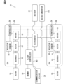
図1、図2に示すように、駆動システム30は、バッテリ31、分配器32、コンバータ33、通信装置34、記憶装置35、飛行制御装置40、EDS50を有している。図2では、ロータ20をRotor、バッテリ31をBattery、分配器32をDistributer、コンバータ33をDC-DC converter、と図示している。また、通信装置34をCommunication Device、記憶装置35をMemory、飛行制御装置40をFlight Controller、と図示している。
As shown in FIGS. 1 and 2, the drive system 30 includes a battery 31, a distributor 32, a converter 33, a communication device 34, a storage device 35, a flight control device 40, and an EDS 50. In FIG. 2, the rotor 20 is shown as Rotor, the battery 31 as Battery, the distributor 32 as Distributor, and the converter 33 as DC-DC converter. Further, the communication device 34 is shown as a Communication Device, the storage device 35 is shown as a Memory, and the flight control device 40 is shown as a Flight Controller.
バッテリ31は、複数のEDS50に電気的に接続されている。バッテリ31は、EDS50に電力を供給する電力供給部であり、電源部に相当する。バッテリ31は、EDS50に直流電圧を印加する直流電圧源である。バッテリ31は、充放電可能な2次電池を有している。この2次電池としては、リチウムイオン電池、ニッケル水素電池などがある。なお、電源部としては、バッテリ31に加えて又は代えて、燃料電池や発電機などが用いられてもよい。
The battery 31 is electrically connected to the plurality of EDSs 50. The battery 31 is a power supply section that supplies power to the EDS 50, and corresponds to a power supply section. The battery 31 is a DC voltage source that applies DC voltage to the EDS 50. The battery 31 has a secondary battery that can be charged and discharged. Examples of this secondary battery include a lithium ion battery and a nickel hydride battery. Note that, in addition to or in place of the battery 31, a fuel cell, a generator, or the like may be used as the power supply section.
分配器32は、バッテリ31及び複数のEDS50に電気的に接続されている。分配器32は、バッテリ31からの電力を複数のEDS50に分配する。EDS50においては、後述する駆動部81が分配器32に電気的に接続されている。バッテリ31の電力は、分配器32を介して駆動部81に供給される。バッテリ31の電圧を高電圧と称すると、駆動部81には高電圧が印加される。なお、バッテリ31の電力が複数のEDS50に供給される構成であれば、分配器32がなくてもよい。分配器32がなくてもよい構成としては、例えば、複数のEDS50のそれぞれに個別に電源部が設けられた構成がある。
The distributor 32 is electrically connected to the battery 31 and the plurality of EDSs 50. Distributor 32 distributes power from battery 31 to a plurality of EDSs 50. In the EDS 50, a drive unit 81, which will be described later, is electrically connected to the distributor 32. Power from the battery 31 is supplied to the drive section 81 via the distributor 32. When the voltage of the battery 31 is referred to as a high voltage, the high voltage is applied to the drive unit 81. Note that if the configuration is such that the power of the battery 31 is supplied to a plurality of EDSs 50, the distributor 32 may not be provided. An example of a configuration that does not require the distributor 32 is a configuration in which each of the plurality of EDSs 50 is individually provided with a power supply section.
飛行制御装置40は、例えばECUであり、EDS50の駆動を制御する。ECUは、Electronic Control Unitの略称である。飛行制御装置40は、例えばプロセッサ、メモリ、I/O、これらを接続するバスを備えるマイクロコンピュータを主体として構成される。マイクロコンピュータはマイコンと称されることがある。メモリは、コンピュータによって読み取り可能なプログラム及びデータを非一時的に格納する非遷移的実体的記憶媒体である。また、非遷移的実体的記憶媒体は、non-transitory tangible storage mediumであり、半導体メモリ又は磁気ディスクなどによって実現される。
The flight control device 40 is, for example, an ECU, and controls the driving of the EDS 50. ECU is an abbreviation for Electronic Control Unit. The flight control device 40 is mainly composed of a microcomputer including, for example, a processor, memory, I/O, and a bus connecting these. A microcomputer is sometimes called a microcomputer. Memory is a non-transitory, tangible storage medium that non-temporarily stores computer-readable programs and data. Further, the non-transitory tangible storage medium is a non-transitory tangible storage medium, and is realized by a semiconductor memory, a magnetic disk, or the like.
飛行制御装置40は、記憶装置35及びEDS50に電気的に接続されている。飛行制御装置40は、メモリ及び記憶装置35の少なくとも一方に記憶された制御プログラムを実行することで、EDS50の駆動に関する各種の処理を実行する。飛行制御装置40は、eVTOL10を飛行させるための飛行制御を行う。この飛行制御には、EDS50の制御、ロータ20のチルト角を変更するチルト角制御、などが含まれている。EDS50においては、後述する駆動制御部54が飛行制御装置40に電気的に接続されている。飛行制御装置40は、駆動制御部54に対して制御信号を出力することでEDS50の制御を行う。
The flight control device 40 is electrically connected to the storage device 35 and the EDS 50. The flight control device 40 executes various processes related to driving the EDS 50 by executing a control program stored in at least one of the memory and the storage device 35. Flight control device 40 performs flight control for causing eVTOL 10 to fly. This flight control includes control of the EDS 50, tilt angle control for changing the tilt angle of the rotor 20, and the like. In the EDS 50, a drive control section 54, which will be described later, is electrically connected to the flight control device 40. The flight control device 40 controls the EDS 50 by outputting a control signal to the drive control section 54.
コンバータ33は、バッテリ31、飛行制御装置40及びEDS50に電気的に接続されている。EDS50においては、駆動制御部54がコンバータ33に電気的に接続されている。コンバータ33は、バッテリ31からの電力を降圧もしくは昇圧して、飛行制御装置40及び駆動制御部54に供給する。コンバータ33が降圧した電力の電圧を低電圧と称すると、飛行制御装置40及び駆動制御部54には低電圧が印加される。この低電圧は、バッテリ31の電圧より低い電圧である。反対にコンバータ33が昇圧した電力の電圧を高電圧と称すると、飛行制御装置40及び駆動制御部54には高電圧が印加される。この高電圧は、バッテリ31の電圧より高い電圧である。
The converter 33 is electrically connected to the battery 31, flight control device 40, and EDS 50. In the EDS 50, a drive control section 54 is electrically connected to the converter 33. Converter 33 steps down or steps up the power from battery 31 and supplies it to flight control device 40 and drive control section 54 . When the voltage of the power stepped down by the converter 33 is referred to as a low voltage, the low voltage is applied to the flight control device 40 and the drive control unit 54. This low voltage is a voltage lower than the voltage of the battery 31. On the other hand, if the voltage of the power boosted by the converter 33 is referred to as a high voltage, the high voltage is applied to the flight control device 40 and the drive control unit 54. This high voltage is higher than the voltage of the battery 31.
EDS50は、ロータ20を回転させるために駆動する装置であり、駆動装置に相当する。EDS50は、ロータ20に対して回転駆動する。EDS50は、Electric Drive Systemの略称である。EDS50は、電駆動装置及びEPUと称されることがある。EPUは、Electric Propulsion Unitの略称である。EDS50は、複数のロータ20のそれぞれに対して個別に設けられている。EDS50は、ロータ軸線に沿ってロータ20に並べられている。複数のEDS50はいずれも、機体11に固定されている。EDS50は、ロータ20を回転可能に支持している。EDS50は、ロータシャフト23に機械的に接続されている。複数のEDS50には、機体11の外側にはみ出した状態で機体11に固定されたEDS50、及び機体11の内側に埋め込まれた状態で機体11に固定されたEDS50、の少なくとも一方が含まれている。
The EDS 50 is a device that drives the rotor 20 to rotate, and corresponds to a drive device. The EDS 50 rotates with respect to the rotor 20. EDS50 is an abbreviation for Electric Drive System. EDS 50 is sometimes referred to as an electric drive unit and EPU. EPU is an abbreviation for Electric Propulsion Unit. The EDS 50 is provided individually for each of the plurality of rotors 20. The EDSs 50 are arranged on the rotor 20 along the rotor axis. All of the plurality of EDSs 50 are fixed to the aircraft body 11. The EDS 50 rotatably supports the rotor 20. EDS 50 is mechanically connected to rotor shaft 23. The plurality of EDSs 50 include at least one of an EDS 50 fixed to the aircraft body 11 in a state of protruding from the outside of the aircraft body 11, and an EDS 50 fixed to the aircraft body 11 in a state of being embedded inside the aircraft body 11. .
ロータ20は、EDS50を介して機体11に固定されている。EDS50は、ロータ20に対して相対的に傾くということが生じないようになっている。EDS50は、ロータ20と共に機体11に対して相対的に傾くことが可能になっている。ロータ20のチルト角が調整される場合、ロータ20と共にEDS50の向きが設定されることになる。
The rotor 20 is fixed to the fuselage 11 via the EDS 50. The EDS 50 is designed to prevent tilting relative to the rotor 20. The EDS 50 can be tilted together with the rotor 20 relative to the fuselage 11. When the tilt angle of the rotor 20 is adjusted, the orientation of the EDS 50 is set together with the rotor 20.
図2に示すように、EDS50は、ギアボックス53、駆動制御部54、回転センサ55、モータ61、駆動部81を有している。図2では、ギアボックス53をGearbox、駆動部81をDriver、駆動制御部54をController、回転センサ55をRotation sensor、モータ61をMotor、と図示している。
As shown in FIG. 2, the EDS 50 includes a gearbox 53, a drive control section 54, a rotation sensor 55, a motor 61, and a drive section 81. In FIG. 2, the gearbox 53 is shown as a Gearbox, the drive section 81 as a Driver, the drive control section 54 as a Controller, the rotation sensor 55 as a Rotation sensor, and the motor 61 as a Motor.
モータ61は、複数相の交流モータであり、例えば3相交流方式の回転電機である。モータ61は、eVTOL10の飛行駆動源である電動機として機能する。モータ61は、回転子及び固定子63(図6参照)を有している。固定子63は、ステータである。回転子は、ロータであり、固定子63に対して相対的に回転する。モータ61は、駆動部81に電気的に接続されている。モータ61には、バッテリ31から駆動部81を介して電力が供給される。モータ61は、駆動部81から供給される電圧及び電流に応じて駆動する。モータ61としては、例えばブラシレスモータが用いられている。なお、モータ61としては、誘導モータやリアクタンスモータが用いられてもよい。
The motor 61 is a multi-phase AC motor, for example, a three-phase AC rotating electric machine. The motor 61 functions as an electric motor that is a flight drive source for the eVTOL 10. The motor 61 has a rotor and a stator 63 (see FIG. 6). Stator 63 is a stator. The rotor is a rotor and rotates relative to the stator 63. Motor 61 is electrically connected to drive section 81 . Electric power is supplied to the motor 61 from the battery 31 via the drive unit 81 . The motor 61 is driven according to the voltage and current supplied from the drive section 81. As the motor 61, for example, a brushless motor is used. Note that as the motor 61, an induction motor or a reactance motor may be used.
ギアボックス53は、モータ61とロータ20とを機械的に接続している。例えば、ロータシャフト23がギアボックス53を介してモータ61の回転軸に機械的に接続されている。ギアボックス53は、モータ61の回転を減速してロータ20に伝達する。ギアボックス53は、複数のギアを含んで構成されており、変速ギア及び減速機と称されることがある。ギアボックス53は、モータ61が有するモータ特性に合わせた構造になっている。
The gearbox 53 mechanically connects the motor 61 and the rotor 20. For example, the rotor shaft 23 is mechanically connected to the rotating shaft of the motor 61 via a gear box 53. Gearbox 53 reduces the rotation speed of motor 61 and transmits the speed to rotor 20 . The gearbox 53 is configured to include a plurality of gears, and is sometimes referred to as a speed change gear or a speed reducer. The gearbox 53 has a structure that matches the motor characteristics of the motor 61.
駆動部81は、モータ61に供給する電力を変換することでモータ61を駆動する。駆動部81はインバータを有している。インバータは、モータ61に供給される電力を直流から交流に変換する。インバータは、電力を変換する電力変換部である。インバータは、複数相のインバータであり、複数相のそれぞれについて電力変換を行う。インバータは、例えば3相インバータである。インバータは、複数のスイッチング素子を含んで構成されたインバータ回路である。このスイッチング素子としては、IGBT及びMOSFET等のパワー素子がある。IGBTは、Insulated Gate Bipolar Transistorの略称である。MOSFETは、Metal-Oxide-Semiconductor Field-Effect Transistorの略称である。スイッチング素子は駆動素子と称されることがある。
The drive unit 81 drives the motor 61 by converting the electric power supplied to the motor 61. The drive section 81 has an inverter. The inverter converts the power supplied to the motor 61 from direct current to alternating current. An inverter is a power converter that converts power. The inverter is a multi-phase inverter, and performs power conversion for each of the plural phases. The inverter is, for example, a three-phase inverter. An inverter is an inverter circuit configured to include a plurality of switching elements. This switching element includes power elements such as IGBT and MOSFET. IGBT is an abbreviation for Insulated Gate Bipolar Transistor. MOSFET is an abbreviation for Metal-Oxide-Semiconductor Field-Effect Transistor. A switching element is sometimes referred to as a driving element.
インバータでは、複数相のそれぞれにおいてスイッチング素子が並列に接続されている。例えばモータ61が3相の交流モータである構成では、U相、V相、W相のそれぞれにおいて、モータ61に対して複数のスイッチング素子が並列に接続されている。なお、複数相のそれぞれにおいては、複数のスイッチング素子が並列に接続されていなくてもよい。例えば、U相、V相、W相のそれぞれにおいて、モータ61に対して複数のスイッチング素子が並列に接続されていなくてもよい。
In an inverter, switching elements are connected in parallel in each of multiple phases. For example, in a configuration where the motor 61 is a three-phase AC motor, a plurality of switching elements are connected in parallel to the motor 61 in each of the U phase, V phase, and W phase. Note that the plurality of switching elements may not be connected in parallel in each of the plurality of phases. For example, a plurality of switching elements may not be connected in parallel to the motor 61 in each of the U phase, V phase, and W phase.
回転センサ55は、モータ61に対して設けられている。回転センサ55は、モータ61の回転数及び回転角度を検出する回転検出部である。回転センサ55は、モータ61の回転数に応じた検出信号を駆動制御部54に対して出力する。回転センサ55は、例えばエンコーダやレゾルバなどを含んで構成されている。
The rotation sensor 55 is provided for the motor 61. The rotation sensor 55 is a rotation detection section that detects the rotation speed and rotation angle of the motor 61. The rotation sensor 55 outputs a detection signal according to the rotation speed of the motor 61 to the drive control section 54. The rotation sensor 55 includes, for example, an encoder and a resolver.
駆動制御部54は、例えばECUであり、駆動部81を制御する。駆動制御部54は、飛行制御装置40と同様に、例えばプロセッサ、メモリ、I/O、これらを接続するバスを備えるマイクロコンピュータを主体として構成される。
The drive control unit 54 is, for example, an ECU, and controls the drive unit 81. Like the flight control device 40, the drive control unit 54 is mainly configured with a microcomputer including, for example, a processor, memory, I/O, and a bus connecting these.
駆動制御部54は、飛行制御装置40及び駆動部81に電気的に接続されている。駆動制御部54は、回転センサ55を含む各種センサに電気的に接続されている。駆動制御部54は、駆動部81に対して指令信号を出力することで駆動部81の制御を行う。駆動制御部54は、飛行制御装置40から入力される制御信号、及び回転センサ55などの各種センサから入力される検出信号、などに応じて指令信号を生成する。駆動部81においては、駆動制御部54から入力された指令信号に応じてインバータが駆動し、インバータによる電力変換が行われる。
The drive control unit 54 is electrically connected to the flight control device 40 and the drive unit 81. The drive control section 54 is electrically connected to various sensors including a rotation sensor 55. The drive control section 54 controls the drive section 81 by outputting a command signal to the drive section 81 . The drive control unit 54 generates command signals in response to control signals input from the flight control device 40, detection signals input from various sensors such as the rotation sensor 55, and the like. In the drive unit 81, the inverter is driven according to the command signal input from the drive control unit 54, and power conversion is performed by the inverter.
各種センサとしては、回転センサ55に加えて、電流センサや電圧センサなどがある。電流センサは、例えば複数相のそれぞれについてモータ61に流れる電流を検出する。電圧センサは、例えばバッテリ31から出力される電圧を検出する。
In addition to the rotation sensor 55, the various sensors include a current sensor, a voltage sensor, and the like. The current sensor detects, for example, a current flowing through the motor 61 for each of a plurality of phases. The voltage sensor detects the voltage output from the battery 31, for example.
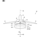
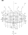
図3に示すように、ロータ20とEDS50とは回転軸線Cmに沿って並べられている。ロータ20は、回転することでeVTOL10に推力及び揚力を生じさせる。ロータ20は、回転することでEDS50側に向けて空気を送る。ロータ20が回転した場合、ロータ軸線に沿って空気が流れる。
As shown in FIG. 3, the rotor 20 and the EDS 50 are arranged along the rotation axis Cm. The rotor 20 causes the eVTOL 10 to generate thrust and lift by rotating. The rotor 20 sends air toward the EDS 50 by rotating. When the rotor 20 rotates, air flows along the rotor axis.
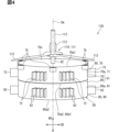
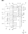
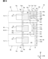
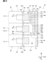
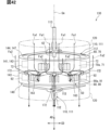
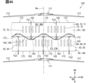
図3、図4に示すように、EDS50は、モータ装置60、インバータ装置80及びフィンカバー140を有している。EDS50は、例えばモータ装置60及びインバータ装置80を1つずつ有している。モータ装置60は、モータ61及びモータハウジング70を有している。モータハウジング70はモータ61を収容している。モータ61は、モータシャフト62を有している。モータシャフト62は、モータ61の回転軸であり、回転子と共に回転する。回転子が回転することをモータ61の回転と称すると、モータ61は、回転軸線Cmを中心に回転する。回転軸線Cmは、直線状に延びる仮想線であり、モータ61の中心線に一致している。回転軸線Cmは、モータ軸線と称されることがある。モータシャフト62は、回転軸線Cmに沿って延びている。
As shown in FIGS. 3 and 4, the EDS 50 includes a motor device 60, an inverter device 80, and a fin cover 140. The EDS 50 includes, for example, one motor device 60 and one inverter device 80. The motor device 60 includes a motor 61 and a motor housing 70. Motor housing 70 accommodates motor 61. Motor 61 has a motor shaft 62. The motor shaft 62 is a rotating shaft of the motor 61, and rotates together with the rotor. When the rotation of the rotor is referred to as rotation of the motor 61, the motor 61 rotates around the rotation axis Cm. The rotation axis Cm is an imaginary line extending linearly and coincides with the center line of the motor 61. The rotation axis Cm is sometimes referred to as a motor axis. The motor shaft 62 extends along the rotation axis Cm.
回転軸線Cmが延びる方向を軸方向ADと称すると、回転軸線Cmについては、軸方向ADと径方向RDと周方向CDとが互いに直交している。径方向RDについては、径方向RDの外側が径方向外側と称され、径方向RDの内側が径方向内側と称されることがある。
When the direction in which the rotational axis Cm extends is referred to as the axial direction AD, the axial direction AD, the radial direction RD, and the circumferential direction CD are orthogonal to each other regarding the rotational axis Cm. Regarding the radial direction RD, the outside of the radial direction RD is sometimes referred to as the radially outer side, and the inside of the radial direction RD is sometimes referred to as the radially inner side.
インバータ装置80は、駆動部81及びインバータハウジング90を有している。インバータハウジング90は、駆動部81を収容している。モータ装置60とインバータ装置80とは、回転軸線Cmに沿って並べられている。
The inverter device 80 includes a drive section 81 and an inverter housing 90. Inverter housing 90 accommodates drive section 81 . The motor device 60 and the inverter device 80 are arranged along the rotation axis Cm.
モータハウジング70とインバータハウジング90とは、回転軸線Cmに沿って並べられている。モータハウジング70及びインバータハウジング90は、全体として筒状に形成されており、回転軸線Cmに沿って延びている。モータハウジング70とインバータハウジング90とは、軸方向ADにおいて互いに重ねられた状態になっている。モータハウジング70とインバータハウジング90とは、ボルト等の固定具により互いに固定されている。モータハウジング70及びインバータハウジング90は、金属材料等により形成されており、熱伝導性を有している。
The motor housing 70 and the inverter housing 90 are arranged along the rotation axis Cm. The motor housing 70 and the inverter housing 90 are formed into a cylindrical shape as a whole, and extend along the rotation axis Cm. The motor housing 70 and the inverter housing 90 are stacked on top of each other in the axial direction AD. The motor housing 70 and the inverter housing 90 are fixed to each other with a fixture such as a bolt. The motor housing 70 and the inverter housing 90 are made of a metal material or the like and have thermal conductivity.
モータハウジング70及びインバータハウジング90は、EDS50のハウジングを構成している。モータ61及び駆動部81は、ロータ20を回転させるために駆動し、その駆動により発熱しやすい。モータ61及び駆動部81が発熱体に相当し、モータハウジング70及びインバータハウジング90がハウジングに相当する。
The motor housing 70 and the inverter housing 90 constitute the housing of the EDS 50. The motor 61 and the drive unit 81 are driven to rotate the rotor 20, and the drive tends to generate heat. The motor 61 and the drive unit 81 correspond to a heating element, and the motor housing 70 and the inverter housing 90 correspond to a housing.
フィンカバー140は、モータハウジング70及びインバータハウジング90を収容している。フィンカバー140は、全体として筒状に形成されており、回転軸線Cmに沿って延びている。フィンカバー140は、軸方向ADにおいてモータハウジング70とインバータハウジング90とにかけ渡された状態になっている。フィンカバー140は、モータハウジング70及びインバータハウジング90を外周側から覆った状態になっている。フィンカバー140は、径方向RDにおいてモータハウジング70及びインバータハウジング90の外側に設けられている。
The fin cover 140 accommodates the motor housing 70 and the inverter housing 90. The fin cover 140 is formed into a cylindrical shape as a whole and extends along the rotation axis Cm. The fin cover 140 extends over the motor housing 70 and the inverter housing 90 in the axial direction AD. The fin cover 140 covers the motor housing 70 and the inverter housing 90 from the outer circumferential side. Fin cover 140 is provided outside motor housing 70 and inverter housing 90 in radial direction RD.
フィンカバー140は、樹脂材料等により形成されており、弾性変形可能になっている。フィンカバー140は、弾性変形した状態でモータハウジング70及びインバータハウジング90に取り付けられている。フィンカバー140は、弾性変形により少なくとも径方向外側に伸びており、径方向内側に向けた復元力によりモータハウジング70及びインバータハウジング90に対する位置が保持された状態になっている。このように、フィンカバー140は、弾性変形による復元力を利用してモータハウジング70及びインバータハウジング90に装着されている。フィンカバー140は、ハウジングカバーに相当する。フィンカバー140の熱伝導性は、モータハウジング70及びインバータハウジング90の熱伝導性よりも低くなっている。
The fin cover 140 is made of a resin material or the like, and is elastically deformable. Fin cover 140 is attached to motor housing 70 and inverter housing 90 in an elastically deformed state. The fin cover 140 extends at least radially outward due to elastic deformation, and is held in position relative to the motor housing 70 and the inverter housing 90 by a restoring force directed radially inward. In this way, the fin cover 140 is attached to the motor housing 70 and the inverter housing 90 using restoring force due to elastic deformation. Fin cover 140 corresponds to a housing cover. The thermal conductivity of the fin cover 140 is lower than that of the motor housing 70 and the inverter housing 90.
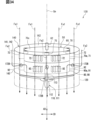
EDS50は、送風装置110が取り付けられている。送風装置110は、EDS50に取り付けられており、EDS50と共にEDSユニット130を構成している。EDSユニット130は、eVTOL10に搭載されている。送風装置110は、ロータ20及びEDS50に対して回転軸線Cmに沿って並べられている。送風装置110は、軸方向ADにおいてロータ20とEDS50との間に設けられている。EDSユニット130が駆動装置ユニットに相当する。
A blower device 110 is attached to the EDS 50. The blower device 110 is attached to the EDS 50, and together with the EDS 50 constitutes an EDS unit 130. The EDS unit 130 is installed in the eVTOL 10. The blower device 110 is arranged along the rotation axis Cm with respect to the rotor 20 and the EDS 50. The blower device 110 is provided between the rotor 20 and the EDS 50 in the axial direction AD. The EDS unit 130 corresponds to a drive unit.
送風装置110は、駆動することで空気を送る。送風装置110は、送風ファン111及びシュラウド120を有している。送風ファン111は、回転軸線Cmを中心に回転する。送風ファン111の中心線は、回転軸線Cmに一致している。送風ファン111は、回転することでEDS50に向けて軸方向ADに空気を送る。送風ファン111は、EDS50を冷却するための冷却風をEDS50に向けて送る。本実施形態では、EDS50にとって送風ファン111側が上流側になる。
The blower device 110 sends air by being driven. The blower 110 includes a blower fan 111 and a shroud 120. The blower fan 111 rotates around the rotation axis Cm. The center line of the blower fan 111 coincides with the rotation axis Cm. The blowing fan 111 sends air in the axial direction AD toward the EDS 50 by rotating. The blower fan 111 sends cooling air toward the EDS 50 to cool the EDS 50 . In this embodiment, the blower fan 111 side is on the upstream side of the EDS 50.
送風ファン111は、ファン羽根112及びファンシャフト113を有している。ファン羽根112は、周方向CDに複数並べられている。ファン羽根112は、ファンヘッドにより連結されている。ファン羽根112は、ファンヘッドから径方向RDに延びている。ファン羽根112は、ファンシャフト113と共に回転する羽根である。ファンシャフト113は、送風ファン111の回転軸であり、ファンヘッドから回転軸線Cmに沿って延びている。
The blowing fan 111 has fan blades 112 and a fan shaft 113. A plurality of fan blades 112 are arranged in the circumferential direction CD. Fan blades 112 are connected by a fan head. The fan blades 112 extend in the radial direction RD from the fan head. The fan blades 112 are blades that rotate together with the fan shaft 113. The fan shaft 113 is a rotation axis of the blower fan 111, and extends from the fan head along the rotation axis Cm.
シュラウド120は、送風ファン111を収容している。シュラウド120は、筒状に形成されており、回転軸線Cmに沿って延びている。シュラウド120は、径方向RDにおいて送風ファン111の外側に設けられている。シュラウド120は、EDS50に取り付けられている。シュラウド120は、例えばモータハウジング70に固定されている。シュラウド120は、樹脂材料等により形成されている。シュラウド120の熱伝導性は、モータハウジング70及びインバータハウジング90の熱伝導性よりも低くなっている。
The shroud 120 houses the blower fan 111. The shroud 120 is formed into a cylindrical shape and extends along the rotation axis Cm. The shroud 120 is provided outside the blower fan 111 in the radial direction RD. Shroud 120 is attached to EDS50. Shroud 120 is fixed to motor housing 70, for example. The shroud 120 is made of a resin material or the like. The thermal conductivity of shroud 120 is lower than that of motor housing 70 and inverter housing 90.
モータシャフト62は、ロータ20及び送風ファン111に接続されている。例えば、モータシャフト62に、ロータシャフト23及びファンシャフト113が接続されている。モータ61が駆動した場合、モータシャフト62と共にロータ20及び送風ファン111が回転する。上述したように、モータシャフト62はギアボックス53を介してロータ20に接続されているが、図3、図4においては、ギアボックス53の図示を省略している。なお、モータシャフト62は、ギアボックス53を介さずにロータ20に接続されていてもよい。また、モータシャフト62はファンシャフト113と一体としてもよい。
The motor shaft 62 is connected to the rotor 20 and the blower fan 111. For example, the motor shaft 62 is connected to the rotor shaft 23 and the fan shaft 113. When the motor 61 is driven, the rotor 20 and the blower fan 111 rotate together with the motor shaft 62. As described above, the motor shaft 62 is connected to the rotor 20 via the gear box 53, but the gear box 53 is not shown in FIGS. 3 and 4. Note that the motor shaft 62 may be connected to the rotor 20 without going through the gear box 53. Further, the motor shaft 62 may be integrated with the fan shaft 113.
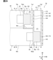
図4、図6に示すように、モータハウジング70は、モータ外周面70a、モータ内周面70b及びモータ端面70cを有している。モータ外周面70a及びモータ内周面70bは、回転軸線Cmに沿って軸方向ADに延びている。モータ外周面70a及びモータ内周面70bは、周方向CDに環状に延びている。モータ外周面70aは、モータハウジング70の外周面である。モータ内周面70bは、モータハウジング70の内周面である。モータ端面70cは、モータハウジング70の端面であり、軸方向ADに並べて一対設けられている。モータ端面70cは、軸方向ADに直交する方向に延びている。モータ外周面70aには、外周上流端70a1及び外周下流端70a2が含まれている。外周上流端70a1は、モータ外周面70aの上流側端部であり、モータ端面70cの外周縁に沿って延びている。外周下流端70a2は、モータ外周面70aの下流側端部である。
As shown in FIGS. 4 and 6, the motor housing 70 has a motor outer peripheral surface 70a, a motor inner peripheral surface 70b, and a motor end surface 70c. The motor outer peripheral surface 70a and the motor inner peripheral surface 70b extend in the axial direction AD along the rotation axis Cm. The motor outer peripheral surface 70a and the motor inner peripheral surface 70b extend annularly in the circumferential direction CD. The motor outer peripheral surface 70a is the outer peripheral surface of the motor housing 70. The motor inner peripheral surface 70b is the inner peripheral surface of the motor housing 70. The motor end faces 70c are end faces of the motor housing 70, and a pair of motor end faces 70c are provided side by side in the axial direction AD. The motor end face 70c extends in a direction perpendicular to the axial direction AD. The motor outer peripheral surface 70a includes an outer peripheral upstream end 70a1 and an outer peripheral downstream end 70a2. The outer peripheral upstream end 70a1 is the upstream end of the motor outer peripheral surface 70a, and extends along the outer peripheral edge of the motor end surface 70c. The outer peripheral downstream end 70a2 is the downstream end of the motor outer peripheral surface 70a.
図4、図5に示すように、モータハウジング70は、モータ外周壁71、モータフィン72及びフランジ75を有している。モータ外周壁71は、全体として筒状に形成されており、回転軸線Cmに沿って延びている。モータ外周壁71は、周方向CDに環状に延びている。モータ外周壁71は、全体として円筒状に形成されている。モータ外周壁71は、モータハウジング70の外周壁である。モータ外周壁71は、ハウジング本体と称されることがある。モータ外周壁71の内側空間がモータハウジング70の内部空間を形成している。モータ外周壁71は、モータ外周面70a及びモータ内周面70bを形成している。
As shown in FIGS. 4 and 5, the motor housing 70 includes a motor outer peripheral wall 71, motor fins 72, and a flange 75. The motor outer peripheral wall 71 is formed into a cylindrical shape as a whole and extends along the rotation axis Cm. The motor outer peripheral wall 71 extends annularly in the circumferential direction CD. The motor outer peripheral wall 71 is formed into a cylindrical shape as a whole. The motor outer peripheral wall 71 is the outer peripheral wall of the motor housing 70. The motor outer peripheral wall 71 is sometimes referred to as a housing body. The inner space of the motor outer peripheral wall 71 forms the inner space of the motor housing 70. The motor outer peripheral wall 71 forms a motor outer peripheral surface 70a and a motor inner peripheral surface 70b.
モータフィン72は、モータ外周面70aに設けられたフィンである。モータフィン72は、モータ装置60の熱を外部に放出することが可能であり、放熱フィンである。モータフィン72は、モータハウジング70の表面積を大きくすることで、モータハウジング70からの放熱効果を高めている。
The motor fins 72 are fins provided on the motor outer peripheral surface 70a. The motor fins 72 are heat radiation fins that can radiate heat from the motor device 60 to the outside. The motor fins 72 increase the heat radiation effect from the motor housing 70 by increasing the surface area of the motor housing 70.
モータフィン72は、モータ外周面70aから突出している。モータフィン72は、モータ外周壁71に一体的に設けられている。モータフィン72は板状に形成されている。モータフィン72は、周方向CDに直交する方向に延びている。モータフィン72は、周方向CDに並んだ一対の板面を有している。モータフィン72は、モータ外周面70aに沿って周方向CDに複数並べられている。複数のモータフィン72は、互いに平行に延びている。モータフィン72は、軸方向ADにおいてモータ外周面70aの中央付近に設けられている。モータフィン72は、モータ外周面70aにおいて外周上流端70a1及び外周下流端70a2の両方から離間した位置にある。
The motor fins 72 protrude from the motor outer peripheral surface 70a. The motor fins 72 are integrally provided on the motor outer peripheral wall 71. The motor fin 72 is formed into a plate shape. The motor fins 72 extend in a direction perpendicular to the circumferential direction CD. The motor fin 72 has a pair of plate surfaces aligned in the circumferential direction CD. A plurality of motor fins 72 are arranged in the circumferential direction CD along the motor outer peripheral surface 70a. The plurality of motor fins 72 extend parallel to each other. The motor fin 72 is provided near the center of the motor outer peripheral surface 70a in the axial direction AD. The motor fin 72 is located at a position spaced apart from both the outer circumferential upstream end 70a1 and the outer circumferential downstream end 70a2 on the motor outer circumferential surface 70a.
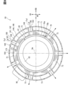
図8に示すように、モータ装置60は、モータフィン群73を有している。モータフィン群73は、複数のモータフィン72を有している。モータフィン群73においては、複数のモータフィン72が密集するように周方向CDに並べられている。モータフィン群73は、モータ外周面70aに沿って周方向CDに複数並べられている。モータフィン群73は、モータハウジング70に含まれている。
As shown in FIG. 8, the motor device 60 has a motor fin group 73. The motor fin group 73 includes a plurality of motor fins 72. In the motor fin group 73, a plurality of motor fins 72 are arranged in the circumferential direction CD so as to be densely arranged. A plurality of motor fin groups 73 are arranged in the circumferential direction CD along the motor outer peripheral surface 70a. Motor fin group 73 is included in motor housing 70 .
図4、図5に示すように、フランジ75は、モータ外周面70aに設けられた突出部である。フランジ75は、送風装置110を固定するための部位である。フランジ75は、周方向CDに複数並べられている。フランジ75は、例えば周方向CDにおいて隣り合う2つのモータフィン群73の間に設けられている。フランジ75には、ボルト等の固定具を用いてシュラウド120等が固定される。なお、送風装置110は、モータ装置60に固定される固定対象である。固定対象としては、送風装置110の他に、ギアボックス53などがある。
As shown in FIGS. 4 and 5, the flange 75 is a protrusion provided on the motor outer peripheral surface 70a. The flange 75 is a part for fixing the blower device 110. A plurality of flanges 75 are arranged in the circumferential direction CD. The flange 75 is provided, for example, between two adjacent motor fin groups 73 in the circumferential direction CD. The shroud 120 and the like are fixed to the flange 75 using fixing tools such as bolts. Note that the blower device 110 is a fixed object that is fixed to the motor device 60. In addition to the blower device 110, there are other objects to be fixed, such as the gear box 53.
図6、図8に示すように、固定子63は、モータハウジング70に収容されている。固定子63は、コイル及びコアなどを有している。固定子63は、モータ61の駆動に伴って発熱しやすい。固定子63においては、例えばコイルへの通電に伴ってコイルが発熱する。固定子63は、ロータ20を回転させるための駆動により発熱することになる。固定子63は、発熱部に相当する。固定子63は、モータ内周面70bに設けられている。固定子63は、モールド樹脂及びボルト等によりモータ内周面70bに固定されている。固定子63は、モータ内周面70bに沿って周方向CDに環状に延びている。例えば、固定子63においては、複数のコイルがモータ内周面70bに沿って周方向CDに並べられている。
As shown in FIGS. 6 and 8, the stator 63 is housed in a motor housing 70. The stator 63 includes a coil, a core, and the like. The stator 63 tends to generate heat as the motor 61 is driven. In the stator 63, the coil generates heat as the coil is energized, for example. The stator 63 generates heat when driven to rotate the rotor 20. The stator 63 corresponds to a heat generating section. The stator 63 is provided on the motor inner peripheral surface 70b. The stator 63 is fixed to the motor inner circumferential surface 70b with molded resin, bolts, and the like. The stator 63 extends annularly in the circumferential direction CD along the motor inner peripheral surface 70b. For example, in the stator 63, a plurality of coils are arranged in the circumferential direction CD along the motor inner peripheral surface 70b.
固定子63とモータフィン72とは、径方向RDに並べられている。固定子63は、モータ外周壁71を介してモータフィン72に熱が伝わりやすい位置に設けられている。固定子63は、外周上流端70a1と外周下流端70a2との間に設けられている。固定子63は、モータフィン72と同様に、外周上流端70a1及び外周下流端70a2の両方から離間した位置にある。なお、固定子63の少なくとも一部が、モータフィン72に径方向RDに並ぶ位置に設けられていればよい。
The stator 63 and the motor fins 72 are arranged in the radial direction RD. The stator 63 is provided at a position where heat is easily transferred to the motor fins 72 via the motor outer peripheral wall 71. The stator 63 is provided between an outer circumferential upstream end 70a1 and an outer circumferential downstream end 70a2. The stator 63, like the motor fins 72, is located at a position spaced apart from both the outer circumferential upstream end 70a1 and the outer circumferential downstream end 70a2. Note that at least a portion of the stator 63 may be provided on the motor fin 72 at a position aligned in the radial direction RD.
図4、図6に示すように、インバータハウジング90は、インバータ外周面90a、インバータ内周面90b及びインバータ端面90cを有している。インバータ外周面90a及びインバータ内周面90bは、回転軸線Cmに沿って軸方向ADに延びている。インバータ外周面90a及びインバータ内周面90bは、周方向CDに環状に延びている。インバータ外周面90aは、インバータハウジング90の外周面である。インバータ内周面90bは、インバータハウジング90の内周面である。インバータ端面90cは、インバータハウジング90の端面であり、軸方向ADに並べて一対設けられている。インバータ端面90cは、軸方向ADに直交する方向に延びている。インバータ外周面90aには、外周上流端90a1及び外周下流端90a2が含まれている。外周上流端90a1は、インバータ外周面90aの上流側端部である。外周下流端90a2は、インバータ外周面90aの下流側端部であり、インバータ端面90cの外周縁に沿って延びている。
As shown in FIGS. 4 and 6, the inverter housing 90 has an inverter outer peripheral surface 90a, an inverter inner peripheral surface 90b, and an inverter end surface 90c. The inverter outer peripheral surface 90a and the inverter inner peripheral surface 90b extend in the axial direction AD along the rotation axis Cm. The inverter outer peripheral surface 90a and the inverter inner peripheral surface 90b extend annularly in the circumferential direction CD. Inverter outer peripheral surface 90a is the outer peripheral surface of inverter housing 90. Inverter inner peripheral surface 90b is the inner peripheral surface of inverter housing 90. The inverter end faces 90c are end faces of the inverter housing 90, and a pair of inverter end faces 90c are provided side by side in the axial direction AD. Inverter end face 90c extends in a direction perpendicular to axial direction AD. The inverter outer peripheral surface 90a includes an outer peripheral upstream end 90a1 and an outer peripheral downstream end 90a2. The outer peripheral upstream end 90a1 is the upstream end of the inverter outer peripheral surface 90a. The outer peripheral downstream end 90a2 is the downstream end of the inverter outer peripheral surface 90a, and extends along the outer peripheral edge of the inverter end surface 90c.
図4、図5に示すように、インバータハウジング90は、インバータ外周壁91及びインバータフィン92を有している。インバータ外周壁91は、全体として筒状に形成されており、回転軸線Cmに沿って延びている。インバータ外周壁91は、周方向CDに環状に延びている。インバータ外周壁91は、全体として円筒状に形成されている。インバータ外周壁91は、インバータハウジング90の外周壁である。インバータ外周壁91は、ハウジング本体と称されることがある。インバータ外周壁91の内側空間がインバータハウジング90の内部空間を形成している。インバータ外周壁91は、インバータ外周面90a及びインバータ内周面90bを形成している。
As shown in FIGS. 4 and 5, the inverter housing 90 has an inverter outer peripheral wall 91 and inverter fins 92. The inverter outer peripheral wall 91 is formed into a cylindrical shape as a whole and extends along the rotation axis Cm. The inverter outer peripheral wall 91 extends annularly in the circumferential direction CD. The inverter outer peripheral wall 91 is formed into a cylindrical shape as a whole. Inverter outer peripheral wall 91 is an outer peripheral wall of inverter housing 90 . The inverter outer peripheral wall 91 is sometimes referred to as a housing body. The inner space of the inverter outer peripheral wall 91 forms the inner space of the inverter housing 90. The inverter outer peripheral wall 91 forms an inverter outer peripheral surface 90a and an inverter inner peripheral surface 90b.
インバータフィン92は、インバータ外周面90aに設けられたフィンである。インバータフィン92は、インバータ装置80の熱を外部に放出することが可能であり、放熱フィンである。インバータフィン92は、インバータハウジング90の表面積を大きくすることで、インバータハウジング90からの放熱効果を高めている。
The inverter fins 92 are fins provided on the inverter outer peripheral surface 90a. The inverter fins 92 are heat radiation fins that can radiate heat from the inverter device 80 to the outside. The inverter fins 92 increase the heat dissipation effect from the inverter housing 90 by increasing the surface area of the inverter housing 90.
インバータフィン92は、インバータ外周面90aから突出している。インバータフィン92は、インバータ外周壁91に一体的に設けられている。インバータフィン92は板状に形成されている。インバータフィン92は、周方向CDに直交する方向に延びている。インバータフィン92は、周方向CDに並んだ一対の板面を有している。インバータフィン92は、インバータ外周面90aに沿って周方向CDに複数並べられている。複数のインバータフィン92は、互いに平行に延びている。インバータフィン92は、軸方向ADにおいてインバータ外周面90aの中央付近に設けられている。インバータフィン92は、インバータ外周面90aにおいて外周上流端90a1及び外周下流端90a2の両方から離間した位置にある。
The inverter fins 92 protrude from the inverter outer peripheral surface 90a. The inverter fins 92 are integrally provided on the inverter outer peripheral wall 91. Inverter fin 92 is formed into a plate shape. The inverter fins 92 extend in a direction perpendicular to the circumferential direction CD. The inverter fin 92 has a pair of plate surfaces arranged in the circumferential direction CD. A plurality of inverter fins 92 are arranged in the circumferential direction CD along the inverter outer peripheral surface 90a. The plurality of inverter fins 92 extend parallel to each other. The inverter fins 92 are provided near the center of the inverter outer peripheral surface 90a in the axial direction AD. The inverter fins 92 are located on the inverter outer peripheral surface 90a at a position spaced apart from both the outer peripheral upstream end 90a1 and the outer peripheral downstream end 90a2.
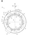
図9に示すように、インバータ装置80は、インバータフィン群93を有している。インバータフィン群93は、複数のインバータフィン92を有している。インバータフィン群93においては、複数のインバータフィン92が密集するように周方向CDに並べられている。インバータフィン群93は、インバータ外周面90aに沿って周方向CDに複数並べられている。インバータフィン群93は、インバータハウジング90に含まれている。
As shown in FIG. 9, the inverter device 80 has an inverter fin group 93. The inverter fin group 93 includes a plurality of inverter fins 92. In the inverter fin group 93, a plurality of inverter fins 92 are arranged closely in the circumferential direction CD. A plurality of inverter fin groups 93 are arranged in the circumferential direction CD along the inverter outer peripheral surface 90a. Inverter fin group 93 is included in inverter housing 90.
インバータ装置80は、インバータコネクタ96を有している。インバータコネクタ96は、インバータ外周面90aから径方向外側に向けて突出している。インバータ装置80を外部機器に接続するためのコネクタ部である。外部機器としては、バッテリ31などがある。インバータコネクタ96は、電力ケーブルが接続可能になっており、電力ケーブルを介して外部機器に接続される。インバータコネクタ96は、インバータハウジング90から径方向外側に向けて突出している。
The inverter device 80 has an inverter connector 96. The inverter connector 96 protrudes radially outward from the inverter outer peripheral surface 90a. This is a connector section for connecting the inverter device 80 to external equipment. The external device includes a battery 31 and the like. A power cable can be connected to the inverter connector 96, and the inverter connector 96 is connected to an external device via the power cable. Inverter connector 96 projects radially outward from inverter housing 90 .
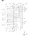
図6、図9に示すように、インバータ装置80は、スイッチモジュール83を有している。スイッチモジュール83は、インバータハウジング90に収容されている。スイッチモジュール83は、駆動部81に含まれており、駆動部81を構成する部品の1つである。スイッチモジュール83は、駆動部81の駆動に伴って発熱しやすい。スイッチモジュール83は、スイッチング素子及び素子保護部を有している。スイッチング素子は、インバータ等を構成する半導体素子である。素子保護部は、樹脂材料により形成されており、スイッチング素子を覆った状態で保護している。スイッチモジュール83は、自身への通電に伴って発熱する。スイッチモジュール83は、ロータ20を回転させるための駆動により発熱することになる。スイッチモジュール83は、発熱部に相当する。
As shown in FIGS. 6 and 9, the inverter device 80 includes a switch module 83. Switch module 83 is housed in inverter housing 90. The switch module 83 is included in the drive unit 81 and is one of the components that make up the drive unit 81. The switch module 83 tends to generate heat as the drive section 81 is driven. The switch module 83 includes a switching element and an element protection section. The switching element is a semiconductor element that constitutes an inverter or the like. The element protection part is formed of a resin material and covers and protects the switching element. The switch module 83 generates heat when it is energized. The switch module 83 generates heat when driven to rotate the rotor 20. The switch module 83 corresponds to a heat generating section.
スイッチモジュール83は、インバータ内周面90bに設けられている。スイッチモジュール83は、接着剤及びボルト等によりインバータ内周面90bに固定されている。スイッチモジュール83は、インバータ内周面90bに沿って周方向CDに複数並べられている。スイッチモジュール83は、複数相に対して複数ずつ設けられている。例えば、スイッチモジュール83は、U相、V相、W相に対して複数ずつ設けられている。U相、V相、W相のそれぞれにおいては、複数のスイッチモジュール83のそれぞれが有するスイッチング素子が並列に接続されている。
The switch module 83 is provided on the inverter inner peripheral surface 90b. The switch module 83 is fixed to the inverter inner circumferential surface 90b with adhesive, bolts, or the like. A plurality of switch modules 83 are arranged in the circumferential direction CD along the inverter inner peripheral surface 90b. A plurality of switch modules 83 are provided for a plurality of phases. For example, a plurality of switch modules 83 are provided for each of the U phase, V phase, and W phase. In each of the U phase, V phase, and W phase, switching elements included in each of the plurality of switch modules 83 are connected in parallel.
スイッチモジュール83とインバータフィン92とは、径方向RDに並べられている。スイッチモジュール83は、インバータ外周壁91を介してインバータフィン92に熱が伝わりやすい位置に設けられている。スイッチモジュール83は、軸方向ADにおいて外周上流端90a1と外周下流端90a2との間に設けられている。スイッチモジュール83は、外周上流端90a1及び外周下流端90a2の両方から離間した位置にある。なお、スイッチモジュール83の少なくとも一部が、インバータフィン92に径方向RDに並ぶ位置にあればよい。
The switch module 83 and the inverter fins 92 are arranged in the radial direction RD. The switch module 83 is provided at a position where heat is easily transferred to the inverter fins 92 via the inverter outer peripheral wall 91. The switch module 83 is provided between an outer circumferential upstream end 90a1 and an outer circumferential downstream end 90a2 in the axial direction AD. The switch module 83 is located at a position spaced apart from both the outer circumferential upstream end 90a1 and the outer circumferential downstream end 90a2. Note that at least a portion of the switch module 83 only needs to be located at a position aligned with the inverter fin 92 in the radial direction RD.
なお、インバータハウジング90においては、図9に示すように、大型のスイッチモジュール83がインバータ内周面90bに沿って周方向CDに複数並べられている。なお、インバータハウジング90においては、スイッチモジュール群がインバータ内周面90bに沿って周方向CDに複数並べられていてもよい。スイッチモジュール群は、複数のスイッチモジュール83が密集するように周方向CDに並べられている。この構成では、スイッチモジュール群とインバータフィン92とが径方向RDに並べられる。
In the inverter housing 90, as shown in FIG. 9, a plurality of large switch modules 83 are arranged in the circumferential direction CD along the inverter inner peripheral surface 90b. In the inverter housing 90, a plurality of switch module groups may be arranged in the circumferential direction CD along the inverter inner peripheral surface 90b. The switch module group is arranged in the circumferential direction CD so that a plurality of switch modules 83 are clustered together. In this configuration, the switch module group and the inverter fins 92 are arranged in the radial direction RD.
図4、図5に示すように、モータ外周面70aとインバータ外周面90aとは、送風ファン111の送風方向に並んでいる。送風ファン111の送風方向は、軸方向ADである。送風方向においては、モータ外周面70aがインバータ外周面90aの上流側にある。このため、モータフィン72は、インバータフィン92の上流側にある。モータフィン72が上流フィンに相当し、インバータフィン92が下流フィンに相当する。モータフィン72とインバータフィン92とは、軸方向ADに並べられている。例えば、モータフィン群73とインバータフィン群93とが軸方向ADに並べられていることで、モータフィン72とインバータフィン92とが軸方向ADに並んでいる。
As shown in FIGS. 4 and 5, the motor outer circumferential surface 70a and the inverter outer circumferential surface 90a are lined up in the air blowing direction of the blower fan 111. The blowing direction of the blower fan 111 is the axial direction AD. In the air blowing direction, the motor outer circumferential surface 70a is on the upstream side of the inverter outer circumferential surface 90a. Therefore, the motor fins 72 are located upstream of the inverter fins 92. The motor fins 72 correspond to upstream fins, and the inverter fins 92 correspond to downstream fins. The motor fins 72 and the inverter fins 92 are arranged in the axial direction AD. For example, since the motor fin group 73 and the inverter fin group 93 are arranged in the axial direction AD, the motor fins 72 and the inverter fins 92 are arranged in the axial direction AD.
モータフィン72の先端部とインバータフィン92の先端部とは、軸方向ADに並んでいる。径方向RDにおいて、モータフィン72の長さ寸法とインバータフィン92の長さ寸法とは、ほぼ同じになっている。モータ外周面70aからのモータフィン72の突出寸法とインバータ外周面90aからのインバータフィン92の突出寸法とは、ほぼ同じになっている。
The tip of the motor fin 72 and the tip of the inverter fin 92 are aligned in the axial direction AD. In the radial direction RD, the length of the motor fin 72 and the length of the inverter fin 92 are substantially the same. The protrusion dimension of the motor fins 72 from the motor outer peripheral surface 70a and the protrusion dimension of the inverter fins 92 from the inverter outer peripheral surface 90a are approximately the same.
フィンカバー140は、モータフィン72及びインバータフィン92を介してモータ外周面70a及びインバータ外周面90aを覆っている。フィンカバー140は、モータハウジング70及びインバータハウジング90を径方向外側から覆っている。フィンカバー140は、モータ外周壁71及びインバータ外周壁91を外周側から覆っている。フィンカバー140は、ハウジングカバーに相当する。フィンカバー140は、ダクト及びケースと称されることがある。
The fin cover 140 covers the motor outer peripheral surface 70a and the inverter outer peripheral surface 90a via the motor fins 72 and the inverter fins 92. Fin cover 140 covers motor housing 70 and inverter housing 90 from the outside in the radial direction. The fin cover 140 covers the motor outer peripheral wall 71 and the inverter outer peripheral wall 91 from the outer peripheral side. Fin cover 140 corresponds to a housing cover. The fin cover 140 is sometimes referred to as a duct and a case.
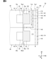
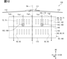
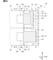
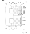
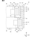
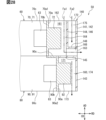
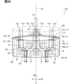
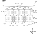
図6、図7に示すように、EDS50は、カバー流路160を有している。カバー流路160は、フィンカバー140とモータ外周面70a及びインバータ外周面90aとの間に形成されている。カバー流路160は、モータ外周面70a及びインバータ外周面90aに沿って周方向CDに延びている。カバー流路160は、全体として環状に形成されている。カバー流路160には、モータフィン72及びインバータフィン92が設けられている。モータフィン72及びインバータフィン92は、カバー流路160に収容された状態になっている。
As shown in FIGS. 6 and 7, the EDS 50 has a cover channel 160. The cover flow path 160 is formed between the fin cover 140, the motor outer circumferential surface 70a, and the inverter outer circumferential surface 90a. The cover flow path 160 extends in the circumferential direction CD along the motor outer circumferential surface 70a and the inverter outer circumferential surface 90a. The cover channel 160 is formed in an annular shape as a whole. A motor fin 72 and an inverter fin 92 are provided in the cover flow path 160. The motor fins 72 and the inverter fins 92 are housed in the cover channel 160.
EDS50においては、ロータ20及び送風ファン111により送られた空気が気流として、カバー流路160を軸方向ADに流れる。このように、ロータ20及び送風ファン111によりカバー流路160に強制的に空気を流すことで、モータフィン72及びインバータフィン92が放熱しやすくなっている。すなわち、固定子63及びスイッチモジュール83にて発生した熱が、モータハウジング70及びインバータハウジング90から放熱しやすくなっている。なお、カバー流路160を流れるのは、モータハウジング70及びインバータハウジング90との熱交換が可能な気体であればよい。
In the EDS 50, air sent by the rotor 20 and the blower fan 111 flows in the cover flow path 160 in the axial direction AD as an airflow. In this way, by forcing air to flow through the cover channel 160 by the rotor 20 and the blower fan 111, the motor fins 72 and the inverter fins 92 can easily radiate heat. That is, the heat generated in the stator 63 and the switch module 83 is easily radiated from the motor housing 70 and the inverter housing 90. Note that any gas flowing through the cover channel 160 may be any gas that can exchange heat with the motor housing 70 and the inverter housing 90.
本実施形態では、カバー流路160を流れる空気が送風ファン111により送られた空気であるとするが、実際には、ロータ20により送られた空気もカバー流路160を流れる。送風ファン111がファンに相当する。EDS50にとっては、送風ファン111及びロータ20の送風方向が軸方向ADである。送風ファン111は、EDS50の上流側にある。
In this embodiment, it is assumed that the air flowing through the cover flow path 160 is the air sent by the ventilation fan 111, but in reality, the air sent by the rotor 20 also flows through the cover flow path 160. The blower fan 111 corresponds to a fan. For the EDS 50, the blowing direction of the blower fan 111 and rotor 20 is the axial direction AD. The blower fan 111 is located upstream of the EDS 50.
図6~図9に示すように、フィンカバー140は、カバー流路160を形成し、且つカバー流路160を仕切っている。フィンカバー140は、外周カバー部141及び流路仕切部144を有している。外周カバー部141は、フィンカバー140の外周面を形成している。外周カバー部141は、全体として筒状に形成されている。外周カバー部141は、周方向CDに環状に延びている。外周カバー部141は、軸方向ADに延びており、例えば外周上流端70a1と外周下流端90a2とにかけ渡された状態になっている。外周カバー部141は、モータ外周面70a及びインバータ外周面90aに平行に延びている。外周カバー部141は、モータフィン72及びインバータフィン92を径方向外側から覆っている。外周カバー部141は、モータフィン72及びインバータフィン92を介して、モータ外周面70a及びインバータ外周面90aを径方向外側から覆っている。外周カバー部141は、モータフィン72及びインバータフィン92から径方向外側に離れた位置に設けられている。
As shown in FIGS. 6 to 9, the fin cover 140 forms a cover flow path 160 and partitions the cover flow path 160. The fin cover 140 has an outer periphery cover part 141 and a channel partition part 144. The outer circumferential cover portion 141 forms the outer circumferential surface of the fin cover 140. The outer circumferential cover portion 141 is formed into a cylindrical shape as a whole. The outer circumferential cover portion 141 extends annularly in the circumferential direction CD. The outer circumferential cover portion 141 extends in the axial direction AD, and is in a state where it spans, for example, an outer circumferential upstream end 70a1 and an outer circumferential downstream end 90a2. The outer circumferential cover portion 141 extends parallel to the motor outer circumferential surface 70a and the inverter outer circumferential surface 90a. The outer circumferential cover portion 141 covers the motor fins 72 and the inverter fins 92 from the outside in the radial direction. The outer circumferential cover portion 141 covers the motor outer circumferential surface 70a and the inverter outer circumferential surface 90a from the outside in the radial direction via the motor fins 72 and the inverter fins 92. The outer circumferential cover portion 141 is provided at a position radially outwardly away from the motor fins 72 and the inverter fins 92.
図6、図7に示すように、外周カバー部141は、モータカバー部142及びインバータカバー部143を有している。モータカバー部142とインバータカバー部143とは、軸方向ADに並べられている。モータカバー部142は、外周カバー部141においてモータフィン72を径方向外側から覆った部位である。インバータカバー部143は、外周カバー部141においてインバータフィン92を径方向外側から覆った部位である。モータカバー部142とインバータカバー部143との境界部は、モータ外周壁71とインバータ外周壁91との境界部と共に、周方向CDに環状に延びている。
As shown in FIGS. 6 and 7, the outer cover section 141 includes a motor cover section 142 and an inverter cover section 143. The motor cover part 142 and the inverter cover part 143 are arranged in the axial direction AD. The motor cover portion 142 is a portion of the outer circumferential cover portion 141 that covers the motor fin 72 from the outside in the radial direction. The inverter cover portion 143 is a portion of the outer circumferential cover portion 141 that covers the inverter fins 92 from the outside in the radial direction. The boundary between the motor cover section 142 and the inverter cover section 143 extends annularly in the circumferential direction CD together with the boundary between the motor outer circumferential wall 71 and the inverter outer circumferential wall 91.
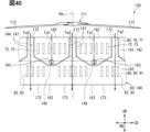
流路仕切部144は、空気がモータフィン72及びインバータフィン92のそれぞれに到達するように、カバー流路160を仕切っている。流路仕切部144は、モータ外周壁71及びインバータ外周壁91と外周カバー部141との間に設けられている。流路仕切部144は、軸仕切部145及び径仕切部146を有している。
The flow path partitioning portion 144 partitions the cover flow path 160 so that air reaches each of the motor fins 72 and the inverter fins 92. The flow path partition part 144 is provided between the motor outer peripheral wall 71 and the inverter outer peripheral wall 91 and the outer peripheral cover part 141. The flow path partitioning section 144 has an axial partitioning section 145 and a radial partitioning section 146.
軸仕切部145は、カバー流路160を軸方向ADに仕切っている。軸仕切部145は、モータフィン72とインバータフィン92との間に設けられている。軸仕切部145は、カバー流路160をモータフィン72側とインバータフィン92側とに仕切っている。軸仕切部145は、板状に形成されており、軸方向ADに直交する方向に延びている。軸仕切部145は、例えばモータ外周壁71とインバータ外周壁91との境界部に設けられている。軸仕切部145は、モータ外周面70a及びインバータ外周面90aに沿って周方向CDに延びている。軸仕切部145は、環状に形成されている。
The shaft partition portion 145 partitions the cover flow path 160 in the axial direction AD. The shaft partition 145 is provided between the motor fin 72 and the inverter fin 92. The shaft partition portion 145 partitions the cover channel 160 into a motor fin 72 side and an inverter fin 92 side. The shaft partition portion 145 is formed into a plate shape and extends in a direction perpendicular to the axial direction AD. The shaft partition portion 145 is provided, for example, at the boundary between the motor outer circumferential wall 71 and the inverter outer circumferential wall 91. The shaft partition portion 145 extends in the circumferential direction CD along the motor outer peripheral surface 70a and the inverter outer peripheral surface 90a. The shaft partition portion 145 is formed in an annular shape.
径仕切部146は、カバー流路160を径方向RDに仕切っている。径仕切部146は、モータフィン72と外周カバー部141との間に設けられている。径仕切部146は、カバー流路160をモータフィン72側と外周カバー部141側とに仕切っている。径仕切部146は、板状に形成されており、径方向RDに直交する方向に延びている。径仕切部146は、モータ外周面70aに沿って周方向CDに延びている。径仕切部146は、環状に形成されている。径仕切部146は、複数のモータフィン72にかけ渡された状態になっている。径仕切部146は、軸仕切部145からモータフィン72側に向けて軸方向ADに延びている。径仕切部146は、モータフィン72及びモータ外周面70aを径方向外側から覆っている。径仕切部146は、例えば軸仕切部145と外周上流端70a1とにかけ渡された状態になっている。
The radial partition portion 146 partitions the cover flow path 160 in the radial direction RD. The diameter partition portion 146 is provided between the motor fin 72 and the outer circumferential cover portion 141. The diametric partition portion 146 partitions the cover flow path 160 into a motor fin 72 side and an outer circumferential cover portion 141 side. The radial partition portion 146 is formed into a plate shape and extends in a direction perpendicular to the radial direction RD. The radial partition portion 146 extends in the circumferential direction CD along the motor outer peripheral surface 70a. The diameter partition portion 146 is formed in an annular shape. The diameter partition portion 146 is in a state where it spans over the plurality of motor fins 72 . The radial partition portion 146 extends in the axial direction AD from the shaft partition portion 145 toward the motor fin 72 side. The radial partition portion 146 covers the motor fin 72 and the motor outer peripheral surface 70a from the outside in the radial direction. The radial partition part 146 is in a state that spans, for example, the shaft partition part 145 and the outer peripheral upstream end 70a1.
径仕切部146は、フィンカバー140の復元力によりモータフィン72に押し付けられた状態になっている。フィンカバー140は、径仕切部146がモータフィン72に押し付けられていることで、モータハウジング70及びインバータハウジング90に対して位置保持されている。なお、図6においては、モータフィン72と径仕切部146とが径方向RDに離れているが、実際には、モータフィン72の先端部と径仕切部146の内周面とは接触している。ただし、フィンカバー140は、ボルト等の固定具によりモータハウジング70及びインバータハウジング90に固定されていてもよい。この構成では、モータフィン72と径仕切部146とが径方向RDに離れていてもよい。
The diameter partition portion 146 is pressed against the motor fin 72 by the restoring force of the fin cover 140. The fin cover 140 is held in position with respect to the motor housing 70 and the inverter housing 90 because the diameter partition portion 146 is pressed against the motor fin 72 . In FIG. 6, the motor fin 72 and the radial partition 146 are separated from each other in the radial direction RD, but in reality, the tip of the motor fin 72 and the inner peripheral surface of the radial partition 146 are in contact with each other. There is. However, the fin cover 140 may be fixed to the motor housing 70 and the inverter housing 90 with fasteners such as bolts. In this configuration, the motor fin 72 and the radial partition portion 146 may be separated in the radial direction RD.
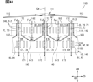
図6~図9に示すように、カバー流路160は、第1流路161及び第2流路171を有している。第1流路161と第2流路171とは、カバー流路160において流路仕切部144により仕切られている。カバー流路160においては、流路仕切部144に対してモータフィン72側の領域が第1流路161である。また、流路仕切部144に対してインバータフィン92側の領域が第2流路171である。第2流路171の一部は、第1流路161の径方向外側に設けられている。
As shown in FIGS. 6 to 9, the cover flow path 160 has a first flow path 161 and a second flow path 171. The first flow path 161 and the second flow path 171 are separated by a flow path partitioning portion 144 in the cover flow path 160 . In the cover flow path 160, a region on the motor fin 72 side with respect to the flow path partition portion 144 is a first flow path 161. Further, the region on the inverter fin 92 side with respect to the flow path partition portion 144 is the second flow path 171 . A portion of the second flow path 171 is provided outside the first flow path 161 in the radial direction.
図6~図8に示すように、第1流路161には、モータフィン72が設けられている。第1流路161には、モータフィン72及びインバータフィン92のうちモータフィン72だけが設けられている。第1流路161は、モータフィン72を収容している。第1流路161は、モータ外周面70a及び流路仕切部144により区画された空間である。第1流路161は、全体として周方向CDに環状に延びている。第1流路161は、モータ外周面70aに径方向RDに並ぶ位置に設けられている一方で、インバータ外周面90aに径方向RDに並ぶ位置には設けられていない。
As shown in FIGS. 6 to 8, a motor fin 72 is provided in the first flow path 161. Of the motor fins 72 and the inverter fins 92, only the motor fins 72 are provided in the first flow path 161. The first flow path 161 accommodates the motor fin 72. The first flow path 161 is a space defined by the motor outer peripheral surface 70a and the flow path partition portion 144. The first flow path 161 as a whole extends annularly in the circumferential direction CD. The first flow paths 161 are provided at positions aligned in the radial direction RD on the motor outer circumferential surface 70a, but are not provided at positions aligned in the radial direction RD on the inverter outer circumferential surface 90a.
第1流路161は、第1流入口162、第1流出口163、第1放熱路164及び第1流出路166を有している。第1流入口162は、第1流路161の流入口であり、第1流路161の上流端に設けられている。第1流入口162は、軸方向ADに開放されている。第1流入口162は、第1流路161を送風ファン111に向けて軸方向ADに開放している。第1流入口162は、モータフィン72よりも上流側に設けられている。第1流入口162は、外周上流端70a1に沿って周方向CDに延びている。第1流入口162は、環状に形成されている。第1流入口162は、第1環状口及び第1軸口に相当する。第1流入口162は、モータフィン72に軸方向ADに並べられている。第1流入口162は、軸方向ADにおいてモータフィン72から上流側に離れた位置にある。
The first flow path 161 has a first inlet 162, a first outlet 163, a first heat radiation path 164, and a first outlet 166. The first inlet 162 is an inlet of the first flow path 161 and is provided at the upstream end of the first flow path 161 . The first inlet 162 is open in the axial direction AD. The first inlet 162 opens the first flow path 161 toward the blower fan 111 in the axial direction AD. The first inlet 162 is provided upstream of the motor fin 72. The first inlet 162 extends in the circumferential direction CD along the outer periphery upstream end 70a1. The first inlet 162 is formed in an annular shape. The first inlet 162 corresponds to a first annular port and a first axial port. The first inflow ports 162 are arranged in the motor fin 72 in the axial direction AD. The first inlet 162 is located away from the motor fin 72 on the upstream side in the axial direction AD.
第1流出口163は、第1流路161の流出口であり、第1流路161の下流端に設けられている。第1流出口163は、第1流路161を径方向外側に向けて開放している。第1流出口163は、第1流路161での空気の流れ方向において、モータフィン72を介して第1流入口162とは反対側にある。第1流出口163は、外周カバー部141の外周面に設けられている。第1流出口163は、例えばモータカバー部142に設けられている。第1流出口163は、周方向CDに複数並べられている。第1流出口163は、軸方向ADにおいてモータフィン72とインバータフィン92との間に設けられている。例えば、第1流出口163の少なくとも一部が、軸方向ADにおいてモータフィン72とインバータフィン92との間に設けられている。第1流出口163は、中間流出口に相当する。
The first outlet 163 is an outlet of the first flow path 161 and is provided at the downstream end of the first flow path 161. The first outlet 163 opens the first flow path 161 radially outward. The first outflow port 163 is located on the opposite side of the first inflow port 162 via the motor fin 72 in the air flow direction in the first flow path 161 . The first outlet 163 is provided on the outer peripheral surface of the outer peripheral cover part 141. The first outlet 163 is provided, for example, in the motor cover portion 142. A plurality of first outflow ports 163 are arranged in the circumferential direction CD. The first outlet 163 is provided between the motor fin 72 and the inverter fin 92 in the axial direction AD. For example, at least a portion of the first outlet 163 is provided between the motor fin 72 and the inverter fin 92 in the axial direction AD. The first outlet 163 corresponds to an intermediate outlet.
第1放熱路164は、第1流路161においてモータフィン72を放熱させるための空間である。第1放熱路164は、モータ外周面70aと径仕切部146との間の空間である。第1放熱路164には、モータフィン72が設けられている。径方向RDにおいては、第1放熱路164の厚さ寸法とモータフィン72の突出寸法とがほぼ同じになっている。これは、モータフィン72と径仕切部146とが接触しているためである。第1放熱路164は、第1流入口162から軸仕切部145に向けて軸方向ADに延びている。第1放熱路164は、第1流入口162を形成している。第1放熱路164の上流端部が第1流入口162である。第1放熱路164は、モータ外周面70aと流路仕切部144との間の空間である。
The first heat radiation path 164 is a space for radiating heat from the motor fins 72 in the first flow path 161. The first heat radiation path 164 is a space between the motor outer circumferential surface 70a and the diameter partition portion 146. A motor fin 72 is provided in the first heat radiation path 164 . In the radial direction RD, the thickness dimension of the first heat radiation path 164 and the protrusion dimension of the motor fin 72 are approximately the same. This is because the motor fin 72 and the diameter partition portion 146 are in contact with each other. The first heat radiation path 164 extends in the axial direction AD from the first inlet 162 toward the shaft partition 145. The first heat radiation path 164 forms a first inlet 162 . The upstream end of the first heat radiation path 164 is the first inlet 162 . The first heat radiation path 164 is a space between the motor outer peripheral surface 70a and the flow path partition part 144.
第1流出路166は、第1放熱路164から径方向外側に向けて延びている。第1流出路166は、第1流出口163を形成している。第1流出路166の下流端部が第1流出口163である。第1流出路166は、径仕切部146及び外周カバー部141の両方を貫通して径方向外側に開放されている。第1流出路166は、第1放熱路164から軸仕切部145に沿って径方向RDに延びている。第1流出路166は、周方向CDに複数並べられている。
The first outflow path 166 extends radially outward from the first heat radiation path 164. The first outflow path 166 forms the first outflow port 163 . The downstream end of the first outflow path 166 is the first outflow port 163 . The first outflow passage 166 passes through both the radial partition part 146 and the outer circumferential cover part 141 and is open to the outside in the radial direction. The first outflow path 166 extends in the radial direction RD from the first heat radiation path 164 along the shaft partition 145. A plurality of first outflow passages 166 are arranged in the circumferential direction CD.
フィンカバー140は、流出形成部148を有している。流出形成部148は、第1流出路166を形成している。流出形成部148は、筒状に形成されており、軸方向ADに延びている。流出形成部148は、流路仕切部144と外周カバー部141とを接続している。流出形成部148の内部空間が第1流出路166になっている。流出形成部148は、軸仕切部145に沿って延びている。流出形成部148は、周方向CDに複数並べられている。流出形成部148は、軸仕切部145の一部を含んで形成されている。なお、流出形成部148は、軸仕切部145を含まずに形成されていてもよい。
The fin cover 140 has an outflow forming part 148. The outflow forming portion 148 forms a first outflow path 166 . The outflow forming portion 148 is formed in a cylindrical shape and extends in the axial direction AD. The outflow forming portion 148 connects the flow path partitioning portion 144 and the outer peripheral cover portion 141. The inner space of the outflow forming portion 148 serves as a first outflow path 166. Outflow formation portion 148 extends along shaft partition portion 145 . A plurality of outflow forming portions 148 are arranged in the circumferential direction CD. The outflow forming part 148 is formed including a part of the shaft partition part 145. Note that the outflow forming portion 148 may be formed without including the shaft partition portion 145.
図8、図10に示すように、第1流出口163は、モータフィン72から周方向CDにずれた位置に設けられている。例えば、第1流出口163は、周方向CDに隣り合う2つのモータフィン群73の間にある。第1流出口163は、周方向CDに隣り合う2つのモータフィン群73のいずれからも周方向CDに離れた位置にある。第1流出口163は、軸方向ADにおいて軸仕切部145とモータフィン72との間にある。第1流出口163は、モータフィン72から軸方向ADに離れた位置にある。第1流出路166は、第1流出口163と共に、モータフィン72から周方向CDにずれた位置に設けられている。なお、第1流出口163は、モータフィン72の一部に軸方向ADに重複する位置にあってもよい。
As shown in FIGS. 8 and 10, the first outlet 163 is provided at a position offset from the motor fin 72 in the circumferential direction CD. For example, the first outlet 163 is located between two motor fin groups 73 adjacent to each other in the circumferential direction CD. The first outlet 163 is located away from both of the two motor fin groups 73 adjacent in the circumferential direction CD in the circumferential direction CD. The first outlet 163 is located between the shaft partition 145 and the motor fin 72 in the axial direction AD. The first outlet 163 is located away from the motor fin 72 in the axial direction AD. The first outflow path 166 and the first outflow port 163 are provided at a position offset from the motor fin 72 in the circumferential direction CD. Note that the first outlet 163 may be located at a position overlapping a part of the motor fin 72 in the axial direction AD.
図6、図7、図9に示すように、第2流路171には、インバータフィン92が設けられている。第2流路171には、モータフィン72及びインバータフィン92のうちインバータフィン92だけが設けられている。第2流路171は、インバータフィン92を収容している。第2流路171は、インバータ外周面90a、流路仕切部144及び外周カバー部141により区画された空間である。第2流路171は、全体として周方向CDに環状に延びている。第2流路171は、軸方向ADに延びており、径仕切部146とインバータ外周面90aとにかけ渡されている。第2流路171の一部は、第1流路161の径方向外側に設けられている。換言すれば、第1流路161は、第2流路171とモータ外周面70aとの間に入り込んだ状態になっている。第1流路161と第2流路171とは、径方向RDに並べられた2重の流路である。
As shown in FIGS. 6, 7, and 9, inverter fins 92 are provided in the second flow path 171. Of the motor fins 72 and the inverter fins 92, only the inverter fins 92 are provided in the second flow path 171. The second flow path 171 accommodates the inverter fins 92. The second flow path 171 is a space defined by the inverter outer peripheral surface 90a, the flow path partition part 144, and the outer peripheral cover part 141. The second flow path 171 extends annularly in the circumferential direction CD as a whole. The second flow path 171 extends in the axial direction AD, and spans the diametrical partition portion 146 and the inverter outer peripheral surface 90a. A portion of the second flow path 171 is provided outside the first flow path 161 in the radial direction. In other words, the first flow path 161 is inserted between the second flow path 171 and the motor outer peripheral surface 70a. The first flow path 161 and the second flow path 171 are double flow paths arranged in the radial direction RD.
第2流路171は、第2流入口172、第2流出口173、第2放熱路174及び第2流入路175を有している。第2流入口172は、第2流路171の流入口であり、第2流路171の上流端に設けられている。第2流入口172は、軸方向ADに開放されている。第2流入口172は、第2流路171を送風ファン111に向けて軸方向ADに開放している。第2流入口172は、インバータフィン92よりも上流側に設けられている。第2流入口172は、外周上流端70a1に沿って周方向CDに延びている。第2流入口172は、環状に形成されている。第2流入口172は、第2環状口及び第2軸口に相当する。
The second flow path 171 has a second inlet 172, a second outlet 173, a second heat radiation path 174, and a second inflow path 175. The second inlet 172 is an inlet of the second flow path 171 and is provided at the upstream end of the second flow path 171 . The second inlet 172 is open in the axial direction AD. The second inlet 172 opens the second flow path 171 toward the blower fan 111 in the axial direction AD. The second inlet 172 is provided upstream of the inverter fins 92. The second inlet 172 extends in the circumferential direction CD along the outer periphery upstream end 70a1. The second inlet 172 is formed in an annular shape. The second inflow port 172 corresponds to a second annular port and a second axial port.
第2流入口172は、第1流入口162よりも径方向外側に設けられている。径方向RDにおいては、第1流入口162がモータ外周面70aと第2流入口172との間に設けられている。第1流入口162と第2流入口172とは、径方向RDに並べられている。第2流入口172は、軸方向AD及び径方向RDのそれぞれにおいてインバータフィン92から離れた位置に設けられている。第2流入口172は、第1流入口162を介してインバータフィン92から径方向外側に離れた位置にある。第2流入口172は、軸方向ADにおいてインバータフィン92から第1流路161を介して上流側に離れた位置にある。径仕切部146は、第1流入口162と第2流入口172との間に設けられている。径仕切部146は、第2流入口172と第2流入口172とを径方向RDに仕切っている。
The second inlet 172 is provided radially outward than the first inlet 162. In the radial direction RD, the first inlet 162 is provided between the motor outer peripheral surface 70a and the second inlet 172. The first inlet 162 and the second inlet 172 are arranged in the radial direction RD. The second inlet 172 is provided at a position away from the inverter fin 92 in each of the axial direction AD and the radial direction RD. The second inlet 172 is located radially outwardly away from the inverter fin 92 via the first inlet 162 . The second inlet 172 is located away from the inverter fin 92 upstream via the first flow path 161 in the axial direction AD. The diametrical partition 146 is provided between the first inlet 162 and the second inlet 172. The radial partition portion 146 partitions the second inlet 172 from the second inlet 172 in the radial direction RD.
第2流出口173は、第2流路171の流出口であり、第2流路171の下流端に設けられている。第2流出口173は、第2流路171を送風ファン111とは反対側に向けて軸方向ADに開放している。第2流出口173は、インバータフィン92よりも下流側に設けられている。第2流出口173は、外周下流端90a2に沿って周方向CDに延びている。第2流出口173は、環状に形成されている。
The second outlet 173 is an outlet of the second flow path 171 and is provided at the downstream end of the second flow path 171. The second outlet 173 opens the second flow path 171 in the axial direction AD toward the side opposite to the blower fan 111 . The second outlet 173 is provided downstream of the inverter fins 92. The second outlet 173 extends in the circumferential direction CD along the outer peripheral downstream end 90a2. The second outlet 173 is formed in an annular shape.
第2流出口173は、径方向RDにおいてインバータ外周面90aと外周カバー部141とにかけ渡された状態になっている。第2流出口173は、第1流入口162及び第2流入口172の両方に軸方向ADに並べられている。径方向RDにおいては、第2流出口173の幅寸法が、第1流入口162の幅寸法及び第2流入口172の幅寸法のいずれよりも大きくなっている。
The second outlet 173 spans the inverter outer peripheral surface 90a and the outer peripheral cover portion 141 in the radial direction RD. The second outflow ports 173 are arranged in both the first inflow port 162 and the second inflow port 172 in the axial direction AD. In the radial direction RD, the width dimension of the second outflow port 173 is larger than both the width dimension of the first inflow port 162 and the width dimension of the second inflow port 172.
第2放熱路174は、第2流路171においてインバータフィン92を放熱させるための空間である。第2放熱路174は、インバータ外周面90aと外周カバー部141との間の空間である。第2放熱路174には、インバータフィン92が設けられている。径方向RDにおいては、第2放熱路174の厚さ寸法がインバータフィン92の突出寸法よりも大きくなっている。これは、外周カバー部141が径仕切部146から第2流入路175の分だけ径方向外側に離れた位置に設けられているためである。第2放熱路174は、第2流出口173から軸仕切部145に向けて軸方向ADに延びている。第2放熱路174は、第2流出口173を形成している。第2放熱路174の下流端部が第2流出口173である。第2放熱路174は、インバータ外周面90aとインバータカバー部143との間の空間である。
The second heat radiation path 174 is a space for radiating heat from the inverter fins 92 in the second flow path 171. The second heat radiation path 174 is a space between the inverter outer peripheral surface 90a and the outer peripheral cover part 141. Inverter fins 92 are provided in the second heat radiation path 174. In the radial direction RD, the thickness dimension of the second heat radiation path 174 is larger than the protrusion dimension of the inverter fin 92. This is because the outer circumferential cover portion 141 is provided at a position radially outwardly away from the radial partition portion 146 by the distance of the second inflow path 175 . The second heat radiation path 174 extends in the axial direction AD from the second outlet 173 toward the shaft partition 145. The second heat radiation path 174 forms a second outlet 173. The downstream end of the second heat radiation path 174 is the second outlet 173 . The second heat radiation path 174 is a space between the inverter outer peripheral surface 90a and the inverter cover portion 143.
第2流入路175は、第2放熱路174から送風ファン111に向けて軸方向ADに延びている。第2流入路175は、第2流入口172を形成している。第2流入路175の上流端部が第2流入口172である。第2流入路175は、流路仕切部144とモータカバー部142との間の空間である。
The second inflow path 175 extends in the axial direction AD from the second heat radiation path 174 toward the ventilation fan 111. The second inflow path 175 forms the second inflow port 172 . The upstream end of the second inflow path 175 is the second inflow port 172 . The second inflow path 175 is a space between the flow path partition section 144 and the motor cover section 142.
第2流入路175は、第1放熱路164よりも径方向外側に設けられている。第2流入路175は、第1放熱路164に径方向RDに並べられている。径方向RDにおいては、第2流入路175が第1放熱路164とモータカバー部142との間にある。第2流入路175は、周方向CDに環状に延びている。第1流出路166及び流出形成部148は、第2流入路175を径方向RDに貫通した状態になっている。
The second inflow path 175 is provided radially outward from the first heat radiation path 164. The second inflow paths 175 are arranged in the first heat radiation path 164 in the radial direction RD. In the radial direction RD, the second inflow path 175 is between the first heat radiation path 164 and the motor cover portion 142. The second inflow path 175 extends annularly in the circumferential direction CD. The first outflow path 166 and the outflow forming portion 148 penetrate the second inflow path 175 in the radial direction RD.
フィンカバー140は、第1流路161及び第2流路171を外周面70a,90aとの間に形成している。流路仕切部144は、モータ外周面70aとの間に第1流路161を形成するように、モータ外周面70aを覆っている。流路仕切部144は、第1カバー部に相当する。外周カバー部141は、流路仕切部144及びインバータ外周面90aとの間に第2流路171を形成するように、流路仕切部144及びインバータ外周面90aを覆っている。外周カバー部141は、第2カバー部に相当する。
The fin cover 140 forms a first flow path 161 and a second flow path 171 between the outer peripheral surfaces 70a and 90a. The flow path partition portion 144 covers the motor outer peripheral surface 70a so as to form a first flow path 161 between the flow path partition portion 144 and the motor outer peripheral surface 70a. The flow path partition part 144 corresponds to a first cover part. The outer circumferential cover portion 141 covers the flow path partition portion 144 and the inverter outer peripheral surface 90a so as to form a second flow path 171 between the flow path partition portion 144 and the inverter outer peripheral surface 90a. The outer circumferential cover portion 141 corresponds to a second cover portion.
第1流路161において、第1流入口162は、空気をフィンカバー140の外部から第2流路171を経由させずに第1流路161に流入させる。第1流出口163は、第1流路161の空気を第2流路171を経由させずにフィンカバー140の外部に流出させる。また、第2流路171において、第2流入口172は、空気をフィンカバー140の外部から第1流路161を経由させずに第2流路171に流入させる。第2流出口173は、第2流路171の空気を第1流路161を経由させずにフィンカバー140の外部に流出させる。
In the first flow path 161 , the first inlet 162 allows air to flow into the first flow path 161 from outside the fin cover 140 without passing through the second flow path 171 . The first outlet 163 allows the air in the first flow path 161 to flow out of the fin cover 140 without passing through the second flow path 171 . Further, in the second flow path 171 , the second inlet 172 allows air to flow into the second flow path 171 from outside the fin cover 140 without passing through the first flow path 161 . The second outlet 173 allows the air in the second flow path 171 to flow out of the fin cover 140 without passing through the first flow path 161 .
図5~図7に示すように、カバー流路160を流れる気流には、第1気流Fa1及び第2気流Fa2が含まれている。第1気流Fa1は、第1流路161を流れる気流である。第1気流Fa1は、第1流入口162から第1放熱路164に流入する。第1気流Fa1は、第1放熱路164においてモータフィン72と熱交換を行う。第1気流Fa1は、モータフィン72から熱が付与された後に、第1流出路166を通って第1流出口163からフィンカバー140の外部に放出される。第1気流Fa1は、第1流路161においてモータフィン72に沿って流れるなどしてモータフィン72を冷却する。第1気流Fa1は、冷却空気と称されることがある。
As shown in FIGS. 5 to 7, the airflow flowing through the cover flow path 160 includes a first airflow Fa1 and a second airflow Fa2. The first airflow Fa1 is an airflow flowing through the first flow path 161. The first airflow Fa1 flows into the first heat radiation path 164 from the first inlet 162. The first airflow Fa1 exchanges heat with the motor fin 72 in the first heat radiation path 164. The first airflow Fa1 is heated by the motor fins 72, and then passes through the first outflow path 166 and is emitted to the outside of the fin cover 140 from the first outflow port 163. The first airflow Fa1 cools the motor fins 72 by flowing along the motor fins 72 in the first flow path 161. The first airflow Fa1 may be referred to as cooling air.
第1放熱路164においては、径仕切部146とモータフィン72の先端部とが接触していることに起因して、第1気流Fa1がモータフィン72の板面に沿って流れやすい。第1気流Fa1は、周方向CDに隣り合う2つのモータフィン72の間を流れやすい。このように、第1気流Fa1がモータフィン72に沿って流れる面積が大きいことで、第1気流Fa1がモータフィン72の熱を吸収しやすくなっている。
In the first heat radiation path 164, the first airflow Fa1 tends to flow along the plate surface of the motor fin 72 due to the contact between the radial partition portion 146 and the tip end of the motor fin 72. The first airflow Fa1 tends to flow between two motor fins 72 adjacent to each other in the circumferential direction CD. In this way, since the first airflow Fa1 has a large area along which it flows along the motor fins 72, the first airflow Fa1 can easily absorb the heat of the motor fins 72.
図8に示すように、第1気流Fa1は、複数の第1流出口163のそれぞれから径方向外側に向けて流出する。この場合、第1気流Fa1は、第1流入口162及び第2流入口172のいずれからも下流側に離れた位置において第1流出口163から流出する。したがって、第1流出口163から流出した第1気流Fa1が、第1流入口162及び第2流入口172に再び流入する、ということが生じないようになっている。
As shown in FIG. 8, the first airflow Fa1 flows out from each of the plurality of first outlet ports 163 toward the outside in the radial direction. In this case, the first airflow Fa1 flows out from the first outlet 163 at a position downstream from both the first inlet 162 and the second inlet 172. Therefore, the first airflow Fa1 flowing out from the first outflow port 163 does not flow into the first inflow port 162 and the second inflow port 172 again.
図5~図7に示すように、第2気流Fa2は、第2流路171を流れる気流である。第2気流Fa2は、第2流入口172から第2流入路175を介して第2放熱路174に流入する。第2気流Fa2は、第2放熱路174においてインバータフィン92と熱交換を行う。第2気流Fa2は、インバータフィン92から熱が付与された後に、第2流出口173からフィンカバー140の外部に放出される。第2気流Fa2は、第2流路171においてインバータフィン92に沿って流れるなどしてインバータフィン92を冷却する。第2気流Fa2は、冷却空気と称されることがある。
As shown in FIGS. 5 to 7, the second airflow Fa2 is an airflow that flows through the second flow path 171. The second airflow Fa2 flows from the second inlet 172 into the second heat radiation path 174 via the second inflow path 175. The second airflow Fa2 exchanges heat with the inverter fins 92 in the second heat radiation path 174. The second airflow Fa2 is given heat by the inverter fins 92 and is then discharged to the outside of the fin cover 140 from the second outlet 173. The second airflow Fa2 cools the inverter fins 92 by flowing along the inverter fins 92 in the second flow path 171. The second airflow Fa2 is sometimes referred to as cooling air.
図10に示すように、第1気流Fa1は、第1流入口162に流入した後、単に軸方向ADに進むことでモータフィン72の板面に沿って流れやすい。このため、第1流路161においては、モータフィン72の熱が第1気流Fa1に付与されやすくなっている。同様に、第2気流Fa2は、第2流入口172に流入した後、単に軸方向ADに進むことがインバータフィン92の板面に沿って流れやすい。このため、第2流路171においては、インバータフィン92の熱が第2気流Fa2に付与されやすくなっている。
As shown in FIG. 10, the first airflow Fa1 flows easily along the plate surface of the motor fin 72 by simply proceeding in the axial direction AD after flowing into the first inflow port 162. Therefore, in the first flow path 161, the heat of the motor fin 72 is easily applied to the first air flow Fa1. Similarly, it is easier for the second airflow Fa2 to flow along the plate surface of the inverter fin 92 by simply proceeding in the axial direction AD after flowing into the second inflow port 172. Therefore, in the second flow path 171, the heat of the inverter fins 92 is easily applied to the second airflow Fa2.
ここまで説明した本実施形態によれば、第2流入口172は、フィンカバー140の外部の空気を第2気流Fa2として、第1流路161を経由させずに第2流路171に流入させる。この構成では、モータフィン72の熱を吸収していない第2気流Fa2が、第2流入口172から第2流路171に流入する。このため、第2流路171に流入した第2気流Fa2について、第2流路171でインバータフィン92の熱を吸収する能力が、すでに第1流路161でモータフィン72の熱を吸収済みであることで低下している、ということを回避できる。例えば、第2気流Fa2がインバータフィン92に到達した時点で、モータフィン72の熱により第2気流Fa2の温度がすでに高くなっている、ということを回避できる。したがって、第1流路161を経由していない第2気流Fa2により、第2流路171でのインバータフィン92の放熱効果を高めることができる。これにより、EDS50及びEDSユニット130の放熱効果を高めることができる。
According to the embodiment described so far, the second inlet 172 allows the air outside the fin cover 140 to flow into the second flow path 171 as the second air flow Fa2 without passing through the first flow path 161. . In this configuration, the second airflow Fa2 that has not absorbed the heat of the motor fins 72 flows into the second flow path 171 from the second inlet 172. Therefore, regarding the second airflow Fa2 flowing into the second flow path 171, the ability to absorb the heat of the inverter fins 92 in the second flow path 171 is lower than that of the second flow path 171, which has already absorbed the heat of the motor fins 72 in the first flow path 161. You can avoid thinking that something is causing the decline. For example, it can be avoided that the temperature of the second airflow Fa2 is already high due to the heat of the motor fins 72 when the second airflow Fa2 reaches the inverter fins 92. Therefore, the heat dissipation effect of the inverter fins 92 in the second flow path 171 can be enhanced by the second air flow Fa2 that does not pass through the first flow path 161. Thereby, the heat dissipation effect of the EDS 50 and the EDS unit 130 can be enhanced.
本実施形態によれば、フィンカバー140においては、径仕切部146がモータ外周面70aとの間に第1流路161を形成しており、外周カバー部141が径仕切部146との間に第2流路171を形成している。この構成では、第1流路161と第2流路171とが径仕切部146により径方向RDに仕切られている。このため、第2気流Fa2は、第1流路161の径方向外側で第2流路171を流れることで、第1流路161を経由せずにインバータフィン92に到達することができる。したがって、第2気流Fa2がインバータフィン92に到達するよりも前に、モータ外周壁71の熱を吸収してしまうということを回避できる。
According to the present embodiment, in the fin cover 140, the radial partition part 146 forms the first flow path 161 between the motor outer peripheral surface 70a, and the outer periphery cover part 141 forms the first flow path 161 between the radial partition part 146 and the radial partition part 146. A second flow path 171 is formed. In this configuration, the first flow path 161 and the second flow path 171 are partitioned in the radial direction RD by the radial partition portion 146. Therefore, the second airflow Fa2 can reach the inverter fins 92 without passing through the first flow path 161 by flowing through the second flow path 171 on the radially outer side of the first flow path 161. Therefore, it is possible to avoid absorbing the heat of the motor outer peripheral wall 71 before the second airflow Fa2 reaches the inverter fins 92.
例えば本実施形態とは異なり、第2流路171がモータフィン72を収容していない一方で、モータ外周面70aにより形成された構成を想定する。この構成では、第2気流Fa2は、第2流路171においてモータフィン72の熱を吸収しない一方で、モータ外周壁71の熱をモータ外周面70aから吸収することがある。このため、第2気流Fa2がインバータフィン92に到達するよりも前に、モータ外周壁71の熱を吸収することが懸念される。
For example, unlike this embodiment, a configuration is assumed in which the second flow path 171 does not accommodate the motor fin 72 but is formed by the motor outer peripheral surface 70a. In this configuration, while the second airflow Fa2 does not absorb the heat of the motor fins 72 in the second flow path 171, it may absorb the heat of the motor outer peripheral wall 71 from the motor outer peripheral surface 70a. Therefore, there is a concern that the second airflow Fa2 may absorb heat from the motor outer peripheral wall 71 before reaching the inverter fins 92.
本実施形態によれば、第1流入口162は、モータ外周面70aに沿って周方向CDに環状に延びている。この構成では、第1流入口162の形状が環状であることを利用して、第1流入口162の開口面積を極力大きくできる。このため、第1流入口162への第1気流Fa1の流入量を極力大きくできる。このように第1流路161に極力多くの第1気流Fa1を流すことができるため、第1気流Fa1によるモータフィン72の冷却効果を高めることができる。
According to the present embodiment, the first inlet 162 extends annularly in the circumferential direction CD along the motor outer peripheral surface 70a. In this configuration, the opening area of the first inlet 162 can be made as large as possible by utilizing the fact that the first inlet 162 has an annular shape. Therefore, the amount of the first airflow Fa1 flowing into the first inlet 162 can be increased as much as possible. In this way, as much of the first airflow Fa1 as possible can flow through the first flow path 161, so that the cooling effect of the motor fins 72 by the first airflow Fa1 can be enhanced.
また、第2流入口172は、インバータ外周面90aに沿って周方向CDに環状に延びている。この構成では、第2流入口172の形状が環状であることを利用して、第2流入口172の開口面積を極力大きくできる。このため、第2流入口172への第2気流Fa2の流入量を極力大きくできる。このように第2流路171に極力多くの第2気流Fa2を流すことができるため、第2気流Fa2によるインバータフィン92の冷却効果を高めることができる。
Further, the second inlet 172 extends annularly in the circumferential direction CD along the inverter outer peripheral surface 90a. In this configuration, the opening area of the second inlet 172 can be made as large as possible by utilizing the fact that the second inlet 172 has an annular shape. Therefore, the amount of second airflow Fa2 flowing into the second inlet 172 can be increased as much as possible. In this way, as much of the second airflow Fa2 as possible can flow through the second flow path 171, so that the cooling effect of the second airflow Fa2 on the inverter fins 92 can be enhanced.
しかも、第2流入口172が第1流入口162の径方向外側に設けられている。この構成では、例えば第1流入口162と第2流入口172とで径方向RDの幅寸法が同じであっても、第2流入口172の開口面積が第1流入口162の開口面積よりも大きい。このように、第2流入口172の開口面積を大きくしやすい構成を実現できる。したがって、第2気流Fa2が第1流路161を経由しないことに加えて、第2流路171を流れる第2気流Fa2の流量が多くなりやすいことにより、インバータフィン群93の冷却効果を高めることができる。
Furthermore, the second inlet 172 is provided on the radially outer side of the first inlet 162. In this configuration, for example, even if the first inflow port 162 and the second inflow port 172 have the same width dimension in the radial direction RD, the opening area of the second inflow port 172 is larger than the opening area of the first inflow port 162. big. In this way, it is possible to realize a configuration in which the opening area of the second inlet 172 can be easily increased. Therefore, in addition to the fact that the second airflow Fa2 does not pass through the first flow path 161, the flow rate of the second airflow Fa2 flowing through the second flow path 171 tends to increase, thereby increasing the cooling effect of the inverter fin group 93. I can do it.
本実施形態によれば、第1流入口162及び第2流入口172が軸方向ADに開放されている。このため、軸方向ADに流れる第1気流Fa1が第1流入口162に流入しやすく、且つ第2気流Fa2が第2流入口172に流入しやすい構成を実現できる。しかも、第1流路161の径方向外側に第2流路171が設けられた構成では、第1流入口162及び第2流入口172の両方を軸方向ADに開放させることで、第1流入口162と第2流入口172とを径方向RDに並べるための構成を簡易化できる。
According to this embodiment, the first inlet 162 and the second inlet 172 are open in the axial direction AD. Therefore, it is possible to realize a configuration in which the first airflow Fa1 flowing in the axial direction AD easily flows into the first inflow port 162, and the second airflow Fa2 easily flows into the second inflow port 172. Moreover, in the configuration in which the second flow path 171 is provided on the radially outer side of the first flow path 161, by opening both the first inlet 162 and the second inlet 172 in the axial direction AD, the first flow The configuration for arranging the inlet 162 and the second inlet 172 in the radial direction RD can be simplified.
本実施形態によれば、第1流出口163の少なくとも一部が、軸方向ADにおいてモータフィン72とインバータフィン92との間に設けられている。この構成では、第1流路161がインバータフィン92の位置まで軸方向ADに延びている必要がない。このため、インバータフィン92が設けられた位置において、第2流路171を周方向CDの全体に延ばすように配置することができる。したがって、第2流路171を流れる第2気流Fa2により、周方向CDにおいてインバータ外周壁91及びインバータフィン92の全体を冷却することができる。
According to this embodiment, at least a portion of the first outlet 163 is provided between the motor fin 72 and the inverter fin 92 in the axial direction AD. With this configuration, it is not necessary for the first flow path 161 to extend in the axial direction AD to the position of the inverter fin 92. Therefore, at the position where the inverter fin 92 is provided, the second flow path 171 can be arranged so as to extend throughout the circumferential direction CD. Therefore, the second airflow Fa2 flowing through the second flow path 171 can cool the entire inverter outer peripheral wall 91 and inverter fins 92 in the circumferential direction CD.
本実施形態では、モータフィン群73とインバータフィン群93とが軸方向ADに並べられ、且つ第1流出口163がモータフィン群73から周方向CDにずれた位置にある。この構成では、軸方向ADにおいて第2流入口172とインバータフィン92との間に第1流出口163を配置する必要がない。このため、第2流入口172に流れ込んだ第2気流Fa2は、インバータフィン92に到達するまでに、第1流出口163を形成する流出形成部148を周方向CDに迂回する必要がない。このように第2気流Fa2がインバータフィン92に到達しやすくなっているため、第2気流Fa2によるインバータフィン92の放熱効果を高めることができる。
In this embodiment, the motor fin group 73 and the inverter fin group 93 are arranged in the axial direction AD, and the first outlet 163 is located at a position offset from the motor fin group 73 in the circumferential direction CD. With this configuration, it is not necessary to arrange the first outlet 163 between the second inlet 172 and the inverter fin 92 in the axial direction AD. Therefore, the second airflow Fa2 flowing into the second inflow port 172 does not need to bypass the outflow forming portion 148 forming the first outflow port 163 in the circumferential direction CD before reaching the inverter fin 92. Since the second airflow Fa2 can thus easily reach the inverter fins 92, the heat dissipation effect of the inverter fins 92 by the second airflow Fa2 can be enhanced.
本実施形態によれば、ロータ20は、回転軸線Cmを中心に回転する。この構成では、ロータ20の回転により流れる空気がカバー流路160に流入するようにカバー流路160を形成することが容易になる。
According to this embodiment, the rotor 20 rotates around the rotation axis Cm. With this configuration, it becomes easy to form the cover flow path 160 so that the air flowing due to the rotation of the rotor 20 flows into the cover flow path 160.
本実施形態によれば、ロータ20は、空気が第1流路161及び第2流路171を流れるように回転する。この構成では、送風ファン111の回転により流れる空気、及びロータ20の回転により流れる空気、の両方が第1流路161及び第2流路171を流れる。このため、カバー流路160を流れる空気量が増加しやすくなる。したがって、モータフィン72及びインバータフィン92の放熱効果をロータ20により高めることができる。
According to this embodiment, the rotor 20 rotates so that air flows through the first flow path 161 and the second flow path 171. In this configuration, both the air flowing due to the rotation of the blower fan 111 and the air flowing due to the rotation of the rotor 20 flow through the first flow path 161 and the second flow path 171. Therefore, the amount of air flowing through the cover flow path 160 tends to increase. Therefore, the heat radiation effect of the motor fins 72 and the inverter fins 92 can be enhanced by the rotor 20.
<第2実施形態>
上記第1実施形態では、第1流出口163がモータフィン群73から周方向CDにずれた位置に設けられていた。これに対して、第2実施形態では、第1流出口163がモータフィン群73から周方向CDにずれていない。第2実施形態で特に説明しない構成、作用、効果については上記第1実施形態と同様である。第2本実施形態では、上記第1実施形態と異なる点を中心に説明する。 <Second embodiment>
In the first embodiment, thefirst outlet 163 is provided at a position offset from the motor fin group 73 in the circumferential direction CD. In contrast, in the second embodiment, the first outlet 163 is not displaced from the motor fin group 73 in the circumferential direction CD. Configurations, operations, and effects that are not particularly described in the second embodiment are the same as those in the first embodiment. The second embodiment will be explained mainly on points different from the first embodiment.
上記第1実施形態では、第1流出口163がモータフィン群73から周方向CDにずれた位置に設けられていた。これに対して、第2実施形態では、第1流出口163がモータフィン群73から周方向CDにずれていない。第2実施形態で特に説明しない構成、作用、効果については上記第1実施形態と同様である。第2本実施形態では、上記第1実施形態と異なる点を中心に説明する。 <Second embodiment>
In the first embodiment, the
図11、図12に示すように、第1流出口163は、モータフィン群73から周方向CDに離れていない。第1流出口163は、モータフィン群73に軸方向ADに並んだ位置に設けられている。すなわち、第1流出口163は、モータフィン72に軸方向ADに並んだ位置にある。このため、すなわち、第1流出口163は、モータフィン72から周方向CDに離れておらず、モータフィン72から周方向CDにずれてもいない。例えば、第1流出口163は、周方向CDにおいてモータフィン群73の中央付近に配置されている。軸方向ADにおいては、第1流入口162と第1流出口163との間にモータフィン72がある。すなわち、第1流入口162と第1流出口163との間にモータフィン群73がある。
As shown in FIGS. 11 and 12, the first outlet 163 is not separated from the motor fin group 73 in the circumferential direction CD. The first outlet 163 is provided in the motor fin group 73 at a position aligned in the axial direction AD. That is, the first outlet 163 is located in line with the motor fin 72 in the axial direction AD. Therefore, the first outlet 163 is not separated from the motor fin 72 in the circumferential direction CD, nor is it displaced from the motor fin 72 in the circumferential direction CD. For example, the first outlet 163 is arranged near the center of the motor fin group 73 in the circumferential direction CD. In the axial direction AD, the motor fin 72 is located between the first inlet 162 and the first outlet 163. That is, the motor fin group 73 is located between the first inlet 162 and the first outlet 163.
本実施形態では、図12に示すように、第1流入口162から流入した第1気流Fa1は、モータフィン72に沿って流れた後に第1流出口163に到達する。このため、第1気流Fa1は、第1流出口163から流出される前に、モータフィン72の熱を吸収しやすくなっている。換言すれば、第1流入口162から流入した第1気流Fa1がモータフィン72の熱を吸収することなく第1流出口163から流出する、ということを抑制できる。したがって、第1気流Fa1によるモータフィン72の冷却効果を高めることができる。
In this embodiment, as shown in FIG. 12, the first airflow Fa1 flowing in from the first inlet 162 reaches the first outlet 163 after flowing along the motor fins 72. Therefore, the first airflow Fa1 easily absorbs the heat of the motor fins 72 before flowing out from the first outlet 163. In other words, it is possible to suppress the first airflow Fa1 flowing in from the first inlet 162 from flowing out from the first outlet 163 without absorbing the heat of the motor fins 72 . Therefore, the cooling effect of the motor fins 72 by the first airflow Fa1 can be enhanced.
<第3実施形態>
上記第1実施形態では、EDS50がモータ装置60及びインバータ装置80を1つずつ有していた。これに対して、第3実施形態では、EDS50がモータ装置60及びインバータ装置80を複数ずつ有している。第3実施形態で特に説明しない構成、作用、効果については上記第1実施形態と同様である。第3本実施形態では、上記第1実施形態と異なる点を中心に説明する。 <Third embodiment>
In the first embodiment described above, theEDS 50 had one motor device 60 and one inverter device 80. On the other hand, in the third embodiment, the EDS 50 includes a plurality of motor devices 60 and a plurality of inverter devices 80. Configurations, operations, and effects that are not particularly described in the third embodiment are the same as those in the first embodiment. The third embodiment will be mainly described with respect to the points that are different from the first embodiment.
上記第1実施形態では、EDS50がモータ装置60及びインバータ装置80を1つずつ有していた。これに対して、第3実施形態では、EDS50がモータ装置60及びインバータ装置80を複数ずつ有している。第3実施形態で特に説明しない構成、作用、効果については上記第1実施形態と同様である。第3本実施形態では、上記第1実施形態と異なる点を中心に説明する。 <Third embodiment>
In the first embodiment described above, the
図13に示すように、EDS50は、モータ装置60及びインバータ装置80を2つずつ有している。すなわち、EDS50は、モータハウジング70及びインバータハウジング90を2つずつ有している。2つのモータ装置60と2つのインバータ装置80とは、軸方向ADに重ねられている。軸方向ADにおいては、2つのモータ装置60が隣り合わせで並べられ、且つ2つのインバータ装置80が隣り合わせで並べられている。モータ装置60とインバータ装置80との境界部1つである。フィンカバー140は、2つのモータ装置60及び2つのインバータ装置80の全てを外周側から覆っている。
As shown in FIG. 13, the EDS 50 has two motor devices 60 and two inverter devices 80. That is, the EDS 50 has two motor housings 70 and two inverter housings 90. The two motor devices 60 and the two inverter devices 80 are stacked in the axial direction AD. In the axial direction AD, two motor devices 60 are arranged next to each other, and two inverter devices 80 are arranged next to each other. This is one boundary between the motor device 60 and the inverter device 80. The fin cover 140 covers all of the two motor devices 60 and the two inverter devices 80 from the outer peripheral side.
図14、図15に示すように、2つのモータ装置60のそれぞれのモータフィン群73は、軸方向ADに並べられている。2つのインバータ装置80のそれぞれのインバータフィン92は、軸方向ADに並べられている。そして、モータ装置60が有するモータフィン群73とインバータ装置80が有するインバータフィン群93とは、軸方向ADに並べられている。
As shown in FIGS. 14 and 15, the motor fin groups 73 of the two motor devices 60 are arranged in the axial direction AD. The inverter fins 92 of the two inverter devices 80 are arranged in the axial direction AD. The motor fin group 73 of the motor device 60 and the inverter fin group 93 of the inverter device 80 are arranged in the axial direction AD.
フィンカバー140においては、径仕切部146が2つのモータ装置60を外周側から覆っている。軸方向ADに隣り合うモータ装置60とインバータ装置80との境界部に対して、軸仕切部145及び第1流出口163が設けられている。上記第1実施形態と同様に、第1流出口163の少なくとも一部が、軸方向ADにおいてモータフィン72とインバータフィン92との間に設けられている。第1気流Fa1は、第1流路161において軸方向ADに並べられた2つのモータフィン72のそれぞれに沿って流れた後に、第1流出口163から流出する。第2気流Fa2は、第2流路171において軸方向ADに並べられた2つのインバータフィン92のそれぞれに沿って流れた後に、第2流出口173から流出する。
In the fin cover 140, the diameter partition portion 146 covers the two motor devices 60 from the outer peripheral side. A shaft partition 145 and a first outlet 163 are provided at the boundary between the motor device 60 and the inverter device 80 that are adjacent to each other in the axial direction AD. Similar to the first embodiment, at least a portion of the first outlet 163 is provided between the motor fin 72 and the inverter fin 92 in the axial direction AD. The first airflow Fa1 flows along each of the two motor fins 72 arranged in the axial direction AD in the first flow path 161, and then flows out from the first outlet 163. The second airflow Fa2 flows along each of the two inverter fins 92 arranged in the axial direction AD in the second flow path 171, and then flows out from the second outlet 173.
<第4実施形態>
上記第1実施形態では、空気が流れる流路が径方向RDに2重に形成されていた。これに対して、第4実施形態では、空気が流れる流路が径方向RDに3重に形成されている。第4実施形態で特に説明しない構成、作用、効果については上記第1実施形態と同様である。第4本実施形態では、上記第1実施形態と異なる点を中心に説明する。 <Fourth embodiment>
In the first embodiment described above, the flow path through which air flows is formed twice in the radial direction RD. In contrast, in the fourth embodiment, the flow paths through which air flows are formed in three layers in the radial direction RD. Configurations, operations, and effects that are not particularly described in the fourth embodiment are the same as those in the first embodiment. The fourth embodiment will be explained mainly on points different from the first embodiment.
図16に示すように、EDS50においては、モータフィン72等の放熱フィンが軸方向ADに3つ並べられている。EDS50は、モータハウジング70等のハウジングを3つ有している。そして、3つのハウジングが軸方向ADに並べられている。例えば、EDS50は、2つのモータ装置60と1つのインバータ装置80とを有している。2つのモータ装置60は、1つのインバータ装置80を介して軸方向ADに並べられている。2つのモータフィン72は、1つのインバータフィン92を介して軸方向ADに並べられている。すなわち、2つのモータフィン群73は、1つのインバータフィン群93を介して軸方向ADに並べられている。
As shown in FIG. 16, in the EDS 50, three heat radiation fins such as the motor fins 72 are arranged in the axial direction AD. The EDS 50 has three housings such as a motor housing 70. The three housings are arranged in the axial direction AD. For example, the EDS 50 includes two motor devices 60 and one inverter device 80. The two motor devices 60 are arranged in the axial direction AD via one inverter device 80. The two motor fins 72 are arranged in the axial direction AD via one inverter fin 92. That is, the two motor fin groups 73 are arranged in the axial direction AD via one inverter fin group 93.
図17、図18、図19に示すように、外周カバー部141は、2つのモータ装置60及び1つのインバータ装置80を径方向外側から覆っている。外周カバー部141は、1つのインバータ装置80を介して2つのモータ装置60にかけ渡されるように、軸方向ADに延びている。外周カバー部141は、軸方向ADにおいて、1つのインバータフィン92を介して2つのインバータフィン92にかけ渡されている。外周カバー部141は、送風ファン111側に設けられた上流側のモータフィン72と、インバータフィン92と、インバータフィン92を介して送風ファン111とは反対側に設けられた下流側のモータフィン72とを、径方向外側から覆っている。
As shown in FIGS. 17, 18, and 19, the outer circumferential cover portion 141 covers the two motor devices 60 and one inverter device 80 from the outside in the radial direction. The outer circumferential cover portion 141 extends in the axial direction AD so as to span the two motor devices 60 via one inverter device 80. The outer circumferential cover portion 141 extends across two inverter fins 92 via one inverter fin 92 in the axial direction AD. The outer circumferential cover part 141 includes an upstream motor fin 72 provided on the side of the blower fan 111, an inverter fin 92, and a downstream motor fin 72 provided on the opposite side of the blower fan 111 via the inverter fin 92. and is covered from the outside in the radial direction.
外周カバー部141は、モータカバー部142として、第1モータカバー部142a及び第2モータカバー部142bを有している。第1モータカバー部142aと第2モータカバー部142bとは、インバータカバー部143を介して軸方向ADに並べられている。第1モータカバー部142aは、上流側のモータフィン72を外周側から覆っている。第2モータカバー部142bは、下流側のモータフィン72を外周側から覆っている。
The outer circumference cover part 141 has a first motor cover part 142a and a second motor cover part 142b as the motor cover part 142. The first motor cover part 142a and the second motor cover part 142b are arranged in the axial direction AD with the inverter cover part 143 in between. The first motor cover portion 142a covers the upstream motor fin 72 from the outer peripheral side. The second motor cover portion 142b covers the motor fin 72 on the downstream side from the outer peripheral side.
流路仕切部144は、軸仕切部145として、第1軸仕切部145a及び第2軸仕切部145bを有している。第1軸仕切部145aと第2軸仕切部145bとは、軸方向ADに並べられている。第1軸仕切部145aは、上流側のモータフィン72とインバータフィン92との間に設けられている。第2軸仕切部145bは、インバータフィン92と下流側のモータフィン72との間に設けられている。
The flow path partition section 144 has a first shaft partition section 145a and a second shaft partition section 145b as the shaft partition section 145. The first shaft partition part 145a and the second shaft partition part 145b are arranged in the axial direction AD. The first shaft partition 145a is provided between the motor fin 72 and the inverter fin 92 on the upstream side. The second shaft partition portion 145b is provided between the inverter fin 92 and the motor fin 72 on the downstream side.
流路仕切部144は、径仕切部146として、第1径仕切部146a及び第2径仕切部146bを有している。第1径仕切部146aと第2径仕切部146bとは、径方向RDに並べられている。第1径仕切部146aは、上流側のモータフィン72を径方向外側から覆っている。第2径仕切部146bは、軸方向ADにおいて、第1径仕切部146aとインバータフィン92とにかけ渡されている。第2径仕切部146bは、第1径仕切部146a及びインバータフィン92を径方向外側から覆っている。第2径仕切部146bは、第1径仕切部146aを介して上流側のモータフィン72を径方向外側から覆っている。
The flow path partitioning section 144 has a first radial partitioning section 146a and a second radial partitioning section 146b as the radial partitioning section 146. The first radial partition portion 146a and the second radial partition portion 146b are arranged in the radial direction RD. The first radial partition portion 146a covers the upstream motor fin 72 from the outside in the radial direction. The second radial partition portion 146b extends between the first radial partition portion 146a and the inverter fin 92 in the axial direction AD. The second radial partition 146b covers the first radial partition 146a and the inverter fin 92 from the outside in the radial direction. The second radial partition 146b covers the upstream motor fin 72 from the outside in the radial direction via the first radial partition 146a.
外周カバー部141は、軸方向ADにおいて、第2径仕切部146bと下流側のモータフィン72とにかけ渡されている。外周カバー部141は、第2径仕切部146b及び下流側のモータフィン72を径方向外側から覆っている。外周カバー部141は、第2径仕切部146bを介してインバータフィン92を径方向外側から覆っている。外周カバー部141は、第1径仕切部146a及び第2径仕切部146bを介してモータフィン72を径方向外側から覆っている。
The outer circumferential cover portion 141 spans the second radial partition portion 146b and the motor fin 72 on the downstream side in the axial direction AD. The outer circumferential cover portion 141 covers the second radial partition portion 146b and the downstream motor fin 72 from the outside in the radial direction. The outer circumferential cover portion 141 covers the inverter fin 92 from the outside in the radial direction via the second radial partition portion 146b. The outer circumferential cover portion 141 covers the motor fin 72 from the outside in the radial direction via the first radial partition portion 146a and the second radial partition portion 146b.
カバー流路160は、第1流路161及び第2流路171に加えて、第3流路181を有している。第1流路161には、上流側のモータフィン72が設けられている。第2流路171には、インバータフィン92が設けられている。第3流路181には、下流側のモータフィン72が設けられている。第1流路161、第2流路171及び第3流路181は、全体として周方向CDに環状に延びている。
The cover flow path 160 has a third flow path 181 in addition to the first flow path 161 and the second flow path 171. The first flow path 161 is provided with an upstream motor fin 72 . Inverter fins 92 are provided in the second flow path 171 . The third flow path 181 is provided with a motor fin 72 on the downstream side. The first flow path 161, the second flow path 171, and the third flow path 181 as a whole extend annularly in the circumferential direction CD.
第2流路171の一部は、第1流路161の径方向外側に設けられている。第3流路181の一部は、第1流路161及び第2流路171の径方向外側に設けられている。第1流路161は、上流側のモータフィン72と第2流路171との間に設けられている。第2流路171は、第1流路161と第3流路181との間に設けられている。第1流路161と第2流路171とは、第1軸仕切部145a及び第1径仕切部146aにより仕切られている。第2流路171と第3流路181とは、第2軸仕切部145b及び第2径仕切部146bにより仕切られている。
A part of the second flow path 171 is provided on the radially outer side of the first flow path 161. A portion of the third flow path 181 is provided outside the first flow path 161 and the second flow path 171 in the radial direction. The first flow path 161 is provided between the upstream motor fin 72 and the second flow path 171. The second flow path 171 is provided between the first flow path 161 and the third flow path 181. The first flow path 161 and the second flow path 171 are partitioned by a first axial partition 145a and a first radial partition 146a. The second flow path 171 and the third flow path 181 are partitioned by a second shaft partition 145b and a second radial partition 146b.
図16、図18に示すように、第1流路161は、上記第1実施形態と同様に、第1流入口162、第1流出口163、第1放熱路164及び第1流出路166を有している。第2流路171は、第2流出口173として、第2流出口173Aを有している。第2流路171は、第2流入口172、第2流出口173A、第2放熱路174及び第2流入路175に加えて、第2流出路176を有している。第3流路181は、第3流入口182、第3流出口183、第3放熱路184を有している。フィンカバー140は、流出形成部148として、第1流出形成部148a及び第2流出形成部148bを有している。
As shown in FIGS. 16 and 18, the first flow path 161 includes a first inlet 162, a first outlet 163, a first heat radiation path 164, and a first outflow path 166, as in the first embodiment. have. The second flow path 171 has a second outlet 173A as the second outlet 173. The second flow path 171 includes a second inflow port 172, a second outflow port 173A, a second heat radiation path 174, a second inflow path 175, and a second outflow path 176. The third flow path 181 has a third inlet 182, a third outlet 183, and a third heat radiation path 184. The fin cover 140 has a first outflow forming part 148a and a second outflow forming part 148b as the outflow forming part 148.
上流側のモータフィン72は、第1放熱路164に設けられている。インバータフィン92は、第2放熱路174に設けられている。下流側のモータフィン72は、第3放熱路184に設けられている。第1放熱路164と第2放熱路174と第3放熱路184とは、軸方向ADに並べられている。これら放熱路164,174,184は、周方向CDに環状に延びている。第1放熱路164は、上流側のモータ外周面70aと第1径仕切部146aとの間に形成されている。第2放熱路174は、インバータ外周面90aと第2径仕切部146bとの間に形成されている。第3放熱路184は、下流側のモータ外周面70aと外周カバー部141との間に形成されている。
The upstream motor fin 72 is provided in the first heat radiation path 164. The inverter fins 92 are provided in the second heat radiation path 174. The motor fin 72 on the downstream side is provided in the third heat radiation path 184. The first heat radiation path 164, the second heat radiation path 174, and the third heat radiation path 184 are arranged in the axial direction AD. These heat radiation paths 164, 174, and 184 extend annularly in the circumferential direction CD. The first heat radiation path 164 is formed between the upstream motor outer peripheral surface 70a and the first radial partition portion 146a. The second heat radiation path 174 is formed between the inverter outer peripheral surface 90a and the second radial partition portion 146b. The third heat radiation path 184 is formed between the motor outer peripheral surface 70a and the outer peripheral cover part 141 on the downstream side.
第1流路161においては、第1流出路166が、第1径仕切部146a及び第2径仕切部146bを貫通して径方向外側に開放されている。第1流路161は、第1流出形成部148aにより形成されている。第1流出形成部148aは、径方向RDにおいて第1径仕切部146aと第1径仕切部146aと外周カバー部141とにかけ渡された状態になっている。第1流路161及び第1流出形成部148aは、第2流入路175及び第3流入路185を径方向RDに貫通している。第1流出口163、第1流出路166及び第1流出形成部148aは、周方向CDに複数並べられている。
In the first flow path 161, the first outflow path 166 penetrates the first radial partition portion 146a and the second radial partition portion 146b and is open to the outside in the radial direction. The first flow path 161 is formed by the first outflow forming portion 148a. The first outflow forming portion 148a is in a state spanning the first radial partition portion 146a, the first radial partition portion 146a, and the outer circumferential cover portion 141 in the radial direction RD. The first flow path 161 and the first outflow forming portion 148a penetrate the second inflow path 175 and the third inflow path 185 in the radial direction RD. A plurality of first outflow ports 163, first outflow paths 166, and first outflow forming portions 148a are arranged in the circumferential direction CD.
図16、図19に示すように、第2流出口173Aは、上記第1実施形態の第2流出口173とは異なり、外周カバー部141に設けられている。第2流出口173Aは、第2流路171を径方向外側に向けて開放している。第2流出口173Aは、外周カバー部141のうちインバータカバー部143に設けられている。第2流出口173Aは、周方向CDに複数並べられている。第2流出口173Aは、軸方向ADにおいて上流側のモータフィン72とインバータフィン92との間に設けられている。例えば、第2流出口173Aの少なくとも一部が、軸方向ADにおいて上流側のモータフィン72とインバータフィン92との間に設けられている。第2流出口173Aは、中間流出口に相当する。
As shown in FIGS. 16 and 19, the second outlet 173A is provided in the outer cover portion 141, unlike the second outlet 173 of the first embodiment. The second outlet 173A opens the second flow path 171 radially outward. The second outlet 173A is provided in the inverter cover section 143 of the outer circumferential cover section 141. A plurality of second outlet ports 173A are arranged in the circumferential direction CD. The second outlet 173A is provided between the motor fin 72 and the inverter fin 92 on the upstream side in the axial direction AD. For example, at least a portion of the second outlet 173A is provided between the motor fin 72 and the inverter fin 92 on the upstream side in the axial direction AD. The second outlet 173A corresponds to an intermediate outlet.
第2流出路176は、第2放熱路174から径方向外側に向けて延びている。第2流出路176は、第2流出口173Aを形成している。第2流出路176は、流路仕切部144及び外周カバー部141の両方を貫通して径方向外側に開放されている。第2流出路176は、第2流出形成部148bにより形成されている。第2流出形成部148bは、径方向RDにおいて第2径仕切部146bと外周カバー部141とにかけ渡された状態になっている。第2流路171及び第2流出形成部148bは、第3流入路185を径方向RDに貫通している。第2流出口173A、第2流出路176及び第2流出形成部148bは、周方向CDに複数並べられている。
The second outflow path 176 extends radially outward from the second heat radiation path 174. The second outflow path 176 forms a second outflow port 173A. The second outflow path 176 penetrates both the flow path partition part 144 and the outer peripheral cover part 141 and is open to the outside in the radial direction. The second outflow path 176 is formed by the second outflow forming portion 148b. The second outflow forming portion 148b is in a state spanning the second radial partition portion 146b and the outer circumferential cover portion 141 in the radial direction RD. The second flow path 171 and the second outflow forming portion 148b penetrate the third inflow path 185 in the radial direction RD. A plurality of second outflow ports 173A, second outflow paths 176, and second outflow forming portions 148b are arranged in the circumferential direction CD.
第3流路181は、他の流路を径方向外側から覆っているという点で、第2流路171と同じ構成になっている。第2流路171は、第1流路161を径方向外側から覆っているのに対して、第3流路181は、第2流路171を径方向外側から覆っている。第3流入口182は、第1流入口162及び第2流入口172と同様に、軸方向ADに開放され、周方向CDに環状に延びている。第3流入路185は、第3放熱路184から軸方向ADに延びており、第3流入口182を形成している。第3流出口183は、上記第1実施形態の第2流出口173と同様に、軸方向ADに開放され、周方向CDに環状に延びている。
The third flow path 181 has the same configuration as the second flow path 171 in that it covers the other flow paths from the outside in the radial direction. The second flow path 171 covers the first flow path 161 from the outside in the radial direction, whereas the third flow path 181 covers the second flow path 171 from the outside in the radial direction. The third inlet 182, like the first inlet 162 and the second inlet 172, is open in the axial direction AD and extends annularly in the circumferential direction CD. The third inflow path 185 extends from the third heat radiation path 184 in the axial direction AD, and forms the third inflow port 182. The third outlet 183 is open in the axial direction AD and extends annularly in the circumferential direction CD, similarly to the second outlet 173 of the first embodiment.
図16~図19に示すように、カバー流路160を流れる気流には、第1気流Fa1及び第2気流Fa2に加えて、第3気流Fa3が含まれている。第3気流Fa3は、第3流路181を流れる気流である。第3気流Fa3は、第3流入口182から第3放熱路184に流入する。第3気流Fa3は、第3放熱路184において下流側のモータフィン72と熱交換を行う。第3気流Fa3は、下流側のモータフィン72の熱が付与された後に、第3流出口183からフィンカバー140の外部に放出される。第3気流Fa3は、第3流路181において下流側のモータフィン72に沿って流れるなどして下流側のモータフィン72を冷却する。第3気流Fa3は、冷却空気と称されることがある。
As shown in FIGS. 16 to 19, the airflow flowing through the cover channel 160 includes a third airflow Fa3 in addition to the first airflow Fa1 and the second airflow Fa2. The third airflow Fa3 is an airflow flowing through the third flow path 181. The third airflow Fa3 flows into the third heat radiation path 184 from the third inlet 182. The third airflow Fa3 exchanges heat with the motor fin 72 on the downstream side in the third heat radiation path 184. The third airflow Fa3 is given heat from the motor fins 72 on the downstream side, and then is discharged to the outside of the fin cover 140 from the third outlet 183. The third airflow Fa3 cools the motor fins 72 on the downstream side by flowing along the motor fins 72 on the downstream side in the third flow path 181. The third airflow Fa3 is sometimes referred to as cooling air.
<第5実施形態>
上記第1実施形態では、外周カバー部141がモータ外周面70a及びインバータ外周面90aに平行に軸方向ADに延びていた。これに対して、第5実施形態では、外周カバー部141がモータ外周面70a及びインバータ外周面90aに対して傾斜している。第5実施形態で特に説明しない構成、作用、効果については上記第1実施形態と同様である。第5本実施形態では、上記第1実施形態と異なる点を中心に説明する。 <Fifth embodiment>
In the first embodiment, the outercircumferential cover portion 141 extends in the axial direction AD parallel to the motor outer circumferential surface 70a and the inverter outer circumferential surface 90a. In contrast, in the fifth embodiment, the outer circumferential cover portion 141 is inclined with respect to the motor outer circumferential surface 70a and the inverter outer circumferential surface 90a. Configurations, operations, and effects that are not particularly described in the fifth embodiment are the same as those in the first embodiment. The fifth embodiment will be described with a focus on points that are different from the first embodiment.
上記第1実施形態では、外周カバー部141がモータ外周面70a及びインバータ外周面90aに平行に軸方向ADに延びていた。これに対して、第5実施形態では、外周カバー部141がモータ外周面70a及びインバータ外周面90aに対して傾斜している。第5実施形態で特に説明しない構成、作用、効果については上記第1実施形態と同様である。第5本実施形態では、上記第1実施形態と異なる点を中心に説明する。 <Fifth embodiment>
In the first embodiment, the outer
図20、図21、図22に示すように、外周カバー部141は、外周カバー部141の外周面が送風ファン111とは反対側を向くように傾斜している。径方向RDでの外周カバー部141とモータ外周面70aとの離間距離は、軸方向ADにおいて送風ファン111とは反対側に向けて徐々に小さくなっている。同様に、径方向RDでの外周カバー部141とインバータ外周面90aとの離間距離は、軸方向ADにおいて送風ファン111とは反対側に向けて徐々に小さくなっている。一方で、径仕切部146は、モータ外周面70aに平行に軸方向ADに延びている。
As shown in FIGS. 20, 21, and 22, the outer circumferential cover portion 141 is inclined so that the outer circumferential surface of the outer circumferential cover portion 141 faces the side opposite to the blower fan 111. The distance between the outer circumferential cover portion 141 and the motor outer circumferential surface 70a in the radial direction RD gradually becomes smaller toward the side opposite to the blower fan 111 in the axial direction AD. Similarly, the distance between the outer circumferential cover portion 141 and the inverter outer circumferential surface 90a in the radial direction RD gradually becomes smaller toward the side opposite to the blower fan 111 in the axial direction AD. On the other hand, the radial partition portion 146 extends in the axial direction AD parallel to the motor outer circumferential surface 70a.
第2流路171は、全体として径方向RDでの厚さ寸法が下流側に向けて徐々に小さくなっている。第2流路171において軸方向ADに直交する断面の断面積は、下流側に向けて徐々に小さくなっている。例えば、径方向RDでの第2流入路175の厚さ寸法は、軸方向ADにおいて第2流出口173に向けて徐々に小さくなっている。また、径方向RDでの第2放熱路174の厚さ寸法は、軸方向ADにおいて第2流出口173に向けて徐々に小さくなっている。
The overall thickness of the second flow path 171 in the radial direction RD gradually decreases toward the downstream side. The cross-sectional area of the cross section perpendicular to the axial direction AD in the second flow path 171 gradually decreases toward the downstream side. For example, the thickness of the second inlet passage 175 in the radial direction RD gradually becomes smaller toward the second outlet port 173 in the axial direction AD. Further, the thickness of the second heat radiation path 174 in the radial direction RD gradually becomes smaller toward the second outlet 173 in the axial direction AD.
図21、図22に示すように、第2気流Fa2は、第2流入口172に流入した後に、外周カバー部141の内周面に沿って第2流出口173に向けて流れる。第2気流Fa2は、第2放熱路174においてインバータフィン92に近づくように、外周カバー部141により径方向内側に向けて案内される。このため、第2気流Fa2は、周方向CDに隣り合う2つのインバータフィン92の間を通りやすくなっている。すなわち、第2気流Fa2は、インバータフィン92の板面に沿って流れやすくなっている。
As shown in FIGS. 21 and 22, the second airflow Fa2 flows toward the second outflow port 173 along the inner circumferential surface of the outer circumferential cover portion 141 after flowing into the second inflow port 172. The second airflow Fa2 is guided radially inward by the outer cover portion 141 so as to approach the inverter fins 92 in the second heat radiation path 174. Therefore, the second airflow Fa2 easily passes between the two inverter fins 92 adjacent to each other in the circumferential direction CD. That is, the second airflow Fa2 easily flows along the plate surface of the inverter fin 92.
<第6実施形態>
上記第1実施形態では、モータフィン72とインバータフィン92とで径方向RDの長さ寸法が同じになっていた。これに対して、第6実施形態では、径方向RDにおいてインバータフィン92の長さ寸法がモータフィン72の長さ寸法よりも大きくなっている。第6実施形態で特に説明しない構成、作用、効果については上記第1実施形態と同様である。第6本実施形態では、上記第1実施形態と異なる点を中心に説明する。 <Sixth embodiment>
In the first embodiment, themotor fins 72 and the inverter fins 92 have the same length in the radial direction RD. On the other hand, in the sixth embodiment, the length of the inverter fin 92 is larger than the length of the motor fin 72 in the radial direction RD. Configurations, operations, and effects that are not particularly described in the sixth embodiment are the same as those in the first embodiment. The sixth embodiment will be described with a focus on points that are different from the first embodiment.
上記第1実施形態では、モータフィン72とインバータフィン92とで径方向RDの長さ寸法が同じになっていた。これに対して、第6実施形態では、径方向RDにおいてインバータフィン92の長さ寸法がモータフィン72の長さ寸法よりも大きくなっている。第6実施形態で特に説明しない構成、作用、効果については上記第1実施形態と同様である。第6本実施形態では、上記第1実施形態と異なる点を中心に説明する。 <Sixth embodiment>
In the first embodiment, the
図23、図24、図25に示すように、径方向RDにおいて、インバータ外周面90aからのインバータフィン92の突出寸法が、モータ外周面70aからのモータフィン72の突出寸法よりも大きくなっている。例えば、インバータフィン92は、径方向RDにおいて径仕切部146よりも径方向外側に突出している。インバータフィン92の先端部は、径方向RDにおいて径仕切部146と外周カバー部141との間にある。インバータフィン92の先端部は、第2流入口172に軸方向ADに並ぶ位置にある。
As shown in FIGS. 23, 24, and 25, in the radial direction RD, the protrusion dimension of the inverter fins 92 from the inverter outer peripheral surface 90a is larger than the protrusion dimension of the motor fins 72 from the motor outer peripheral surface 70a. . For example, the inverter fins 92 protrude more radially outward than the radial partition portion 146 in the radial direction RD. The tip portion of the inverter fin 92 is located between the radial partition portion 146 and the outer circumferential cover portion 141 in the radial direction RD. The tip portion of the inverter fin 92 is located in line with the second inlet 172 in the axial direction AD.
インバータフィン92の先端部は、外周カバー部141に接触している。例えば、外周カバー部141は、フィンカバー140の復元力によりインバータフィン92に押し付けられた状態になっている。フィンカバー140は、外周カバー部141がインバータフィン92に押し付けられていることで、モータハウジング70及びインバータハウジング90に対して位置保持されている。
The tip of the inverter fin 92 is in contact with the outer cover portion 141. For example, the outer circumferential cover portion 141 is pressed against the inverter fins 92 by the restoring force of the fin cover 140. The fin cover 140 is held in position with respect to the motor housing 70 and the inverter housing 90 because the outer circumferential cover portion 141 is pressed against the inverter fins 92 .
なお、径方向RDにおいては、インバータフィン92と外周カバー部141との位置関係が、モータフィン72と径仕切部146との位置関係に同じになっていることが好ましい。例えば、モータフィン72と径仕切部146とが径方向RDに離れていれば、インバータフィン92と外周カバー部141とが径方向RDに離れていてもよい。この構成では、径方向RDにおいてインバータフィン92と外周カバー部141との離間距離が、モータフィン72と径仕切部146との離間距離にほぼ同じになっていてもよい。
Note that in the radial direction RD, it is preferable that the positional relationship between the inverter fins 92 and the outer circumferential cover part 141 is the same as the positional relationship between the motor fins 72 and the radial partition part 146. For example, if the motor fins 72 and the radial partition part 146 are apart in the radial direction RD, the inverter fins 92 and the outer circumferential cover part 141 may be apart in the radial direction RD. In this configuration, the distance between the inverter fins 92 and the outer circumferential cover portion 141 in the radial direction RD may be approximately the same as the distance between the motor fins 72 and the radial partition portion 146.
図24、図25に示すように、第2気流Fa2は、第2流入口172に流入した後に、単に外周カバー部141に沿って軸方向ADに流れることでインバータフィン92の先端部に到達しやすくなっている。これは、インバータフィン92が第2流入口172及び第2流入路175に軸方向ADに並んでいるためである。このため、第2気流Fa2は、第2流入路175から第2放熱路174に流れ込んだ後、径方向内側に向けて流れなくても、インバータフィン92に到達しやすくなっている。このように、第2気流Fa2は、単に外周カバー部141に沿って軸方向ADに流れていても、インバータフィン92の板面に沿って流れやすくなっている。
As shown in FIGS. 24 and 25, the second airflow Fa2 flows into the second inlet 172 and then simply flows in the axial direction AD along the outer circumferential cover portion 141 to reach the tip of the inverter fin 92. It's getting easier. This is because the inverter fins 92 are lined up at the second inlet 172 and the second inflow path 175 in the axial direction AD. Therefore, after the second airflow Fa2 flows into the second heat radiation path 174 from the second inflow path 175, it easily reaches the inverter fins 92 even if it does not flow radially inward. In this way, even if the second airflow Fa2 simply flows in the axial direction AD along the outer circumferential cover portion 141, it easily flows along the plate surface of the inverter fin 92.
<第7実施形態>
上記第1実施形態では、モータ外周面70aとインバータ外周面90aとが軸方向ADに並べられていた。これに対して、第7実施形態では、インバータ外周面90aがモータ外周面70aよりも径方向外側に設けられている。第7実施形態で特に説明しない構成、作用、効果については上記第1実施形態と同様である。第7本実施形態では、上記第1実施形態と異なる点を中心に説明する。 <Seventh embodiment>
In the first embodiment, the motor outerperipheral surface 70a and the inverter outer peripheral surface 90a are arranged in the axial direction AD. In contrast, in the seventh embodiment, the inverter outer circumferential surface 90a is provided radially outward than the motor outer circumferential surface 70a. Configurations, operations, and effects that are not particularly described in the seventh embodiment are the same as those in the first embodiment. The seventh embodiment will be described with a focus on points that are different from the first embodiment.
上記第1実施形態では、モータ外周面70aとインバータ外周面90aとが軸方向ADに並べられていた。これに対して、第7実施形態では、インバータ外周面90aがモータ外周面70aよりも径方向外側に設けられている。第7実施形態で特に説明しない構成、作用、効果については上記第1実施形態と同様である。第7本実施形態では、上記第1実施形態と異なる点を中心に説明する。 <Seventh embodiment>
In the first embodiment, the motor outer
図26、図27、図28に示すように、インバータハウジング90は、モータハウジング70よりも径方向外側に突出している。例えば、インバータ外周壁91がモータ外周壁71よりも径方向外側に突出している。インバータ外周面90aは、モータ外周面70aから径方向外側に離れた位置に設けられている。インバータフィン92は、インバータ外周面90aと共に、モータ外周面70aから径方向外側に離れた位置に設けられている。インバータ外周面90aがモータ外周面70aから径方向外側に突出した分だけ、インバータフィン92は、モータフィン72よりも径方向外側に突出している。
As shown in FIGS. 26, 27, and 28, the inverter housing 90 protrudes further radially outward than the motor housing 70. For example, the inverter outer circumferential wall 91 protrudes more radially outward than the motor outer circumferential wall 71. The inverter outer circumferential surface 90a is provided at a position radially outwardly away from the motor outer circumferential surface 70a. The inverter fins 92 are provided at a position apart from the motor outer circumferential surface 70a in the radial direction along with the inverter outer circumferential surface 90a. The inverter fins 92 protrude further radially outward than the motor fins 72 by the amount that the inverter outer circumferential surface 90a protrudes radially outward from the motor outer circumferential surface 70a.
図27、図28に示すように、インバータフィン92の先端部は、上記第6実施形態と同様に、径方向RDにおいて径仕切部146と外周カバー部141との間にある。例えば、インバータフィン92の先端部が外周カバー部141に接触する程度に、インバータ外周面90aがモータ外周面70aから径方向外側に離間した位置にある。第2気流Fa2は、上記第6実施形態と同様に、単に外周カバー部141に沿って軸方向ADに流れていても、インバータフィン92の板面に沿って流れやすくなっている。
As shown in FIGS. 27 and 28, the tip portion of the inverter fin 92 is located between the radial partition portion 146 and the outer circumferential cover portion 141 in the radial direction RD, similarly to the sixth embodiment. For example, the inverter outer circumferential surface 90a is spaced radially outward from the motor outer circumferential surface 70a to such an extent that the tips of the inverter fins 92 contact the outer circumferential cover part 141. Similarly to the sixth embodiment, the second airflow Fa2 easily flows along the plate surface of the inverter fin 92 even if it simply flows in the axial direction AD along the outer circumferential cover portion 141.
第2放熱路174は、インバータ外周面90aがモータ外周面70aから径方向外側に突出した分だけ、径方向RDに薄くなっている。インバータ外周面90aは、径方向外側に向けて外周カバー部141に近い位置に配置されている。このため、第2気流Fa2は、第2流入路175から第2放熱路174に流れ込んだ後、インバータ外周面90aに沿って流れやすくなっている。したがって、第2気流Fa2は、インバータ外周壁91の熱をインバータ外周面90aから吸収しやすくなっている。
The second heat radiation path 174 is thinner in the radial direction RD by the amount that the inverter outer peripheral surface 90a protrudes radially outward from the motor outer peripheral surface 70a. The inverter outer peripheral surface 90a is disposed at a position close to the outer peripheral cover portion 141 toward the outside in the radial direction. Therefore, the second airflow Fa2 flows easily along the inverter outer peripheral surface 90a after flowing into the second heat radiation path 174 from the second inflow path 175. Therefore, the second airflow Fa2 easily absorbs the heat of the inverter outer peripheral wall 91 from the inverter outer peripheral surface 90a.
<第8実施形態>
上記第1実施形態では、第1放熱路164と第2放熱路174とが軸方向ADに並べられていた。これに対して、第8実施形態では、第2放熱路174が第1放熱路164から径方向外側に離れた位置に設けられている。第8実施形態で特に説明しない構成、作用、効果については上記第1実施形態と同様である。第8本実施形態では、上記第1実施形態と異なる点を中心に説明する。 <Eighth embodiment>
In the first embodiment, the firstheat radiation path 164 and the second heat radiation path 174 are arranged in the axial direction AD. In contrast, in the eighth embodiment, the second heat radiation path 174 is provided at a position radially outwardly away from the first heat radiation path 164. Configurations, operations, and effects not particularly described in the eighth embodiment are the same as those in the first embodiment. The eighth embodiment will be described with a focus on points that are different from the first embodiment.
上記第1実施形態では、第1放熱路164と第2放熱路174とが軸方向ADに並べられていた。これに対して、第8実施形態では、第2放熱路174が第1放熱路164から径方向外側に離れた位置に設けられている。第8実施形態で特に説明しない構成、作用、効果については上記第1実施形態と同様である。第8本実施形態では、上記第1実施形態と異なる点を中心に説明する。 <Eighth embodiment>
In the first embodiment, the first
図29、図30に示すように、インバータ外周壁91は、径仕切部146に軸方向ADに並ぶ位置に設けられている。インバータ外周面90aは、径仕切部146の外周面に軸方向ADに並べられている。本実施形態では、上記第7実施形態と同様に、インバータ外周面90aがモータ外周面70aよりも径方向外側に設けられている。インバータハウジング90は、第1放熱路164よりも径方向外側に突出している。インバータハウジング90においては、上流側のインバータ端面90cが第1放熱路164を区画した状態になっている。
As shown in FIGS. 29 and 30, the inverter outer peripheral wall 91 is provided at a position aligned with the radial partition portion 146 in the axial direction AD. The inverter outer circumferential surface 90a is arranged on the outer circumferential surface of the radial partition portion 146 in the axial direction AD. In this embodiment, similarly to the seventh embodiment, the inverter outer circumferential surface 90a is provided radially outward than the motor outer circumferential surface 70a. Inverter housing 90 protrudes radially outward from first heat radiation path 164 . In the inverter housing 90, the upstream inverter end face 90c defines a first heat radiation path 164.
第2流路171では、径方向RDにおいて第2流入路175の厚さ寸法と第2放熱路174の厚さ寸法とがほぼ同じになっている。また、第2流入路175と第2放熱路174とは、軸方向ADに並べられている。第2流路171においては、径方向RDでの厚さ寸法が軸方向ADで均一になっている。このため、第2流入口172に流入した第2気流Fa2は、単に第2流入路175及び第2放熱路174を流れることで、インバータフィン92の板面に沿って流れやすくなっている。
In the second flow path 171, the thickness of the second inflow path 175 and the thickness of the second heat radiation path 174 are approximately the same in the radial direction RD. Further, the second inflow path 175 and the second heat radiation path 174 are arranged in the axial direction AD. In the second flow path 171, the thickness dimension in the radial direction RD is uniform in the axial direction AD. Therefore, the second airflow Fa2 that has entered the second inlet 172 simply flows through the second inflow path 175 and the second heat radiation path 174, thereby making it easier to flow along the plate surface of the inverter fin 92.
<第9実施形態>
上記第1実施形態では、第2流入口172がモータフィン72よりも上流側に設けられていた。これに対して、第9実施形態では、第2流入口172がモータフィン72よりも下流側に設けられている。第9実施形態で特に説明しない構成、作用、効果については上記第1実施形態と同様である。第9本実施形態では、上記第1実施形態と異なる点を中心に説明する。 <Ninth embodiment>
In the first embodiment described above, thesecond inlet 172 was provided upstream of the motor fin 72. In contrast, in the ninth embodiment, the second inlet 172 is provided downstream of the motor fin 72. Configurations, operations, and effects that are not particularly described in the ninth embodiment are the same as those in the first embodiment. The ninth embodiment will be described with a focus on the points that are different from the first embodiment.
上記第1実施形態では、第2流入口172がモータフィン72よりも上流側に設けられていた。これに対して、第9実施形態では、第2流入口172がモータフィン72よりも下流側に設けられている。第9実施形態で特に説明しない構成、作用、効果については上記第1実施形態と同様である。第9本実施形態では、上記第1実施形態と異なる点を中心に説明する。 <Ninth embodiment>
In the first embodiment described above, the
図31、図33に示すように、第2流路171は、第2流入口172として第2流入口172Aを有している。第2流入口172Aは、上記第1実施形態の第2流入口172とは異なり、外周カバー部141に設けられている。第2流入口172Aは、第2流路171を径方向外側に向けて開放している。第2流入口172Aは、外周カバー部141のうちインバータカバー部143に設けられている。第2流入口172Aは、周方向CDに複数並べられている。第2流入口172Aは、軸方向ADにおいてモータフィン72とインバータフィン92との間に設けられている。例えば、第2流入口172Aの少なくとも一部が、軸方向ADにおいてモータフィン72とインバータフィン92との間に設けられている。第2流入口172Aは、第2カバー口に相当する。
As shown in FIGS. 31 and 33, the second flow path 171 has a second inlet 172A as a second inlet 172. As shown in FIGS. The second inlet 172A is different from the second inlet 172 of the first embodiment, and is provided in the outer cover portion 141. The second inlet 172A opens the second flow path 171 radially outward. The second inlet 172A is provided in the inverter cover section 143 of the outer circumferential cover section 141. A plurality of second inflow ports 172A are arranged in the circumferential direction CD. The second inlet 172A is provided between the motor fin 72 and the inverter fin 92 in the axial direction AD. For example, at least a portion of the second inlet 172A is provided between the motor fin 72 and the inverter fin 92 in the axial direction AD. The second inflow port 172A corresponds to a second cover port.
図32、図33に示すように、軸仕切部145は、上記第1実施形態と同様に、第1放熱路164と第2放熱路174との間に設けられており、第1放熱路164と第2放熱路174とを軸方向ADに仕切っている。径仕切部146は、上記第1実施形態とは異なり、インバータフィン92と外周カバー部141との間に設けられている。径仕切部146は、インバータフィン92を径方向外側から覆っている。径仕切部146は、インバータフィン92の先端部に接触していてもよく、接触していなくてもよい。
As shown in FIGS. 32 and 33, the shaft partition 145 is provided between the first heat radiation path 164 and the second heat radiation path 174, as in the first embodiment. and the second heat radiation path 174 in the axial direction AD. The diameter partition portion 146 is provided between the inverter fin 92 and the outer circumferential cover portion 141, unlike the first embodiment. The radial partition portion 146 covers the inverter fin 92 from the outside in the radial direction. The diameter partition portion 146 may or may not be in contact with the tip of the inverter fin 92.
第1流出路166は、上記第1実施形態とは異なり、第1放熱路164から下流側に向けて軸方向ADに延びている。第1流出路166は、第1流出口163として、第1流出口163Aを有している。第1流出口163Aは、第1流出路166を下流側に向けて軸方向ADに開放している。第1流出口163Aは、第2流出口173の径方向外側に設けられている。第1流出口163Aは、第2流出口173に沿って径方向RDに延びている。第1流出口163Aは、環状に形成されている。
Unlike the first embodiment described above, the first outflow path 166 extends in the axial direction AD from the first heat radiation path 164 toward the downstream side. The first outflow path 166 has a first outflow port 163A as the first outflow port 163. The first outflow port 163A opens the first outflow path 166 in the axial direction AD toward the downstream side. The first outlet 163A is provided on the radially outer side of the second outlet 173. The first outlet 163A extends in the radial direction RD along the second outlet 173. The first outlet 163A is formed in an annular shape.
図31、図33に示すように、第2流入口172Aは、第2流入路175の流入口である。第2流入路175は、第2放熱路174から径方向外側に向けて延びている。第2流入路175は、径仕切部146及び外周カバー部141の両方を貫通して径方向外側に開放されている。第2流入路175は、第2放熱路174から軸仕切部145に沿って径方向RDに延びている。第2流入路175は、周方向CDに複数並べられている。
As shown in FIGS. 31 and 33, the second inlet 172A is the inlet of the second inflow path 175. The second inflow path 175 extends radially outward from the second heat radiation path 174. The second inflow path 175 penetrates both the radial partition portion 146 and the outer circumferential cover portion 141 and is open to the outside in the radial direction. The second inflow path 175 extends in the radial direction RD from the second heat radiation path 174 along the shaft partition 145. A plurality of second inflow passages 175 are arranged in the circumferential direction CD.
フィンカバー140は、流入形成部149を有している。流入形成部149は、第2流入路175及び第2流入口172Aを形成している。流入形成部149は、筒状に形成されており、軸方向ADに延びている。流入形成部149は、流路仕切部144と外周カバー部141とを接続している。流入形成部149の内部空間が第2流入路175になっている。流入形成部149は、軸仕切部145に沿って延びている。流入形成部149は、軸仕切部145の一部を含んで形成されている。流入形成部149は、周方向CDに複数並べられている。なお、流入形成部149は、軸仕切部145を含まずに形成されていてもよい。
The fin cover 140 has an inflow forming portion 149. The inflow forming portion 149 forms a second inflow path 175 and a second inflow port 172A. The inflow forming portion 149 is formed in a cylindrical shape and extends in the axial direction AD. The inflow forming portion 149 connects the flow path partitioning portion 144 and the outer peripheral cover portion 141. The internal space of the inflow forming portion 149 serves as a second inflow path 175 . The inflow formation portion 149 extends along the shaft partition portion 145 . The inflow formation part 149 is formed including a part of the shaft partition part 145. A plurality of inflow forming portions 149 are arranged in the circumferential direction CD. Note that the inflow forming portion 149 may be formed without including the shaft partition portion 145.
図31に示すように、EDSユニット130は、送風ファン111として、送風ファン111Aを有している。送風ファン111Aは、EDS50の下流側に設けられている。EDS50の下流側には、送風ファン111Aを有する送風装置110が設けられている。送風ファン111Aは、EDS50とは反対側に向けて軸方向ADに空気を送る。送風ファン111Aは、第1流路161の空気を吸い出すように第1流出口163Aから空気を流出させることで、外部の空気を第1流入口162に流入させる。また、送風ファン111Aは、第2流路171の空気を吸い出すように第2流出口173から空気を流出させることで、外部の空気を第2流出口173に流入させる。送風ファン111Aは、下流ファンに相当する。
As shown in FIG. 31, the EDS unit 130 includes a blower fan 111A as the blower fan 111. The blower fan 111A is provided downstream of the EDS 50. A blower device 110 having a blower fan 111A is provided downstream of the EDS 50. The blower fan 111A sends air in the axial direction AD toward the side opposite to the EDS 50. The blower fan 111A causes external air to flow into the first inlet 162 by causing air to flow out from the first outlet 163A so as to suck out the air in the first flow path 161. Further, the blower fan 111A causes external air to flow into the second outlet 173 by causing air to flow out from the second outlet 173 so as to suck out the air in the second flow path 171. The blower fan 111A corresponds to a downstream fan.
カバー流路160においては、送風ファン111Aの駆動に伴って第1気流Fa1及び第2気流Fa2が流れる。第1気流Fa1は、第1流出口163Aからの流出に伴って第1流入口162に流入する。第2気流Fa2は、第2流出口173からの流出に伴って第2流入口172Aから流入する。
In the cover flow path 160, the first airflow Fa1 and the second airflow Fa2 flow as the blower fan 111A is driven. The first airflow Fa1 flows into the first inflow port 162 as it flows out from the first outflow port 163A. The second airflow Fa2 flows in from the second inflow port 172A as it flows out from the second outflow port 173.
本実施形態によれば、第2流入口172Aの少なくとも一部が、軸方向ADにおいてモータフィン72とインバータフィン92との間に設けられている。この構成では、第2流入口172Aがモータフィン72よりも下流側に設けられた構成を実現しやすい。すなわち、第2流路171にモータフィン72を設けずに済む構成を容易に実現できる。このため、第2流入口172Aに流入した第2気流Fa2がモータフィン72の熱を吸収するということを確実に抑制できる。
According to this embodiment, at least a portion of the second inlet 172A is provided between the motor fin 72 and the inverter fin 92 in the axial direction AD. With this configuration, it is easy to realize a configuration in which the second inlet 172A is provided downstream of the motor fin 72. That is, a configuration in which the motor fin 72 is not provided in the second flow path 171 can be easily realized. Therefore, it is possible to reliably prevent the second airflow Fa2 flowing into the second inlet 172A from absorbing the heat of the motor fins 72.
本実施形態によれば、送風ファン111Aが第2流出口173の下流に設けられている。この構成では、送風ファン111Aの送風により第2流出口173から吸い出されるように第2気流Fa2が流れることで、第2気流Fa2を第2流入口172Aから流入させることができる。このため、第2流入口172Aが径方向外側に開放されていても、第2流入口172Aに第2気流Fa2が流入する構成を実現できる。
According to this embodiment, the blower fan 111A is provided downstream of the second outlet 173. In this configuration, the second airflow Fa2 flows so as to be sucked out from the second outflow port 173 by the air blowing from the ventilation fan 111A, so that the second airflow Fa2 can be caused to flow in from the second inflow port 172A. Therefore, even if the second inlet 172A is opened radially outward, it is possible to realize a configuration in which the second airflow Fa2 flows into the second inlet 172A.
<第10実施形態>
上記第9実施形態では、フィンカバー140が流路仕切部144を有していた。これに対して、第10実施形態では、フィンカバー140が流路仕切部144を有していない。第10実施形態で特に説明しない構成、作用、効果については上記第9実施形態と同様である。第10本実施形態では、上記第9実施形態と異なる点を中心に説明する。 <Tenth embodiment>
In the ninth embodiment described above, thefin cover 140 had the flow path partition part 144. On the other hand, in the tenth embodiment, the fin cover 140 does not have the channel partition part 144. The configuration, operation, and effects not particularly described in the tenth embodiment are the same as those in the ninth embodiment. The tenth embodiment will be described with a focus on the points that are different from the ninth embodiment.
上記第9実施形態では、フィンカバー140が流路仕切部144を有していた。これに対して、第10実施形態では、フィンカバー140が流路仕切部144を有していない。第10実施形態で特に説明しない構成、作用、効果については上記第9実施形態と同様である。第10本実施形態では、上記第9実施形態と異なる点を中心に説明する。 <Tenth embodiment>
In the ninth embodiment described above, the
図34、図35に示すように、フィンカバー140は、第1流路161と第2流路171とを仕切っていない。カバー流路160には、流路仕切部144が設けられていない。第1流路161と第2流路171とは、軸方向ADに並べられており、連続した空間になっている。カバー流路160においては、モータフィン72を収容した空間が第1流路161であり、インバータフィン92を収容した空間が第2流路171である。第1流路161と第2流路171との境界部は、モータ外周面70aとインバータ外周面90aとの境界部に径方向RDに並んでいる。第1流出口163は、第1流路161と第2流路171との境界部に含まれている。
As shown in FIGS. 34 and 35, the fin cover 140 does not partition the first flow path 161 and the second flow path 171. The cover flow path 160 is not provided with the flow path partition portion 144 . The first flow path 161 and the second flow path 171 are arranged in the axial direction AD and form a continuous space. In the cover channel 160, the space that accommodates the motor fins 72 is the first channel 161, and the space that accommodates the inverter fins 92 is the second channel 171. The boundary between the first flow path 161 and the second flow path 171 is aligned in the radial direction RD at the boundary between the motor outer circumferential surface 70a and the inverter outer circumferential surface 90a. The first outlet 163 is included in the boundary between the first flow path 161 and the second flow path 171.
第2流路171は、第2流入口172として第2流入口172Bを有している。第2流入口172Bは、上記第9実施形態の第2流入口172Aと同様に、外周カバー部141に設けられている。第2流入口172Bは、周方向CDに複数並べられている。第2流入口172Bは、軸方向ADにおいてモータフィン72とインバータフィン92との間に設けられている。例えば、第2流入口172Bの少なくとも一部が、軸方向ADにおいてモータフィン72とインバータフィン92との間に設けられている。第2流入口172Bは、第2カバー口及び第2共通口に相当する。
The second flow path 171 has a second inlet 172B as the second inlet 172. The second inlet 172B is provided in the outer circumferential cover portion 141 similarly to the second inlet 172A of the ninth embodiment. A plurality of second inflow ports 172B are arranged in the circumferential direction CD. The second inlet 172B is provided between the motor fin 72 and the inverter fin 92 in the axial direction AD. For example, at least a portion of the second inlet 172B is provided between the motor fin 72 and the inverter fin 92 in the axial direction AD. The second inflow port 172B corresponds to a second cover port and a second common port.
外周カバー部141には、第2流入口172Bを形成する貫通孔が設けられている。この貫通孔は、外周カバー部141を径方向RDに貫通している。この貫通孔は、第2流入口172Bに加えて第2流入路175を形成している。この貫通孔の内側空間が第2流入路175である。外周カバー部141において、この貫通孔を形成する部位は、第2流入路175を形成する流入形成部149でもある。
The outer circumferential cover portion 141 is provided with a through hole that forms a second inlet 172B. This through hole penetrates the outer circumferential cover portion 141 in the radial direction RD. This through hole forms a second inflow path 175 in addition to the second inflow port 172B. The inner space of this through hole is the second inflow path 175. In the outer circumferential cover portion 141, the portion where this through hole is formed is also the inflow forming portion 149 that forms the second inflow path 175.
本実施形態では、上記第9実施形態と同様に、送風ファン111AがEDS50の下流側に設けられている。送風ファン111Aは、第2流路171の空気を吸い出すように第2流出口173から空気を流出させることで、外部の空気を第2流入口172Bに流入させる。また、送風ファン111Aは、第2流路171の空気を吸い出すように第2流出口173から空気を流出させることで、外部の空気を第1流入口162に流入させる。
In this embodiment, a blower fan 111A is provided downstream of the EDS 50, as in the ninth embodiment. The blower fan 111A causes external air to flow into the second inlet 172B by causing air to flow out from the second outlet 173 so as to suck out the air in the second flow path 171. Further, the blower fan 111A causes external air to flow into the first inlet 162 by causing air to flow out from the second outlet 173 so as to suck out the air in the second flow path 171.
カバー流路160においては、上記第9実施形態と同様に、送風ファン111Aの駆動に伴って第1気流Fa1及び第2気流Fa2が流れる。第2気流Fa2は、第2流出口173からの流出に伴って第2流入口172Bに流入する。第1気流Fa1は、第2流出口173からの第2気流Fa2の流出に伴って、第1流入口162に流入する。そして、第1流入口162に流入した第1気流Fa1は、第1流路161から第2流路171を経由して第2流出口173から外部に流出する。第2気流Fa2は、第2流入口172Bから第2流路171に流入した後、第1流路161から第2流路171に流入してきた第1流路161と合流しながらインバータフィン92に沿って流れる。
In the cover flow path 160, as in the ninth embodiment, the first airflow Fa1 and the second airflow Fa2 flow as the blower fan 111A is driven. The second airflow Fa2 flows into the second inflow port 172B as it flows out from the second outflow port 173. The first airflow Fa1 flows into the first inflow port 162 as the second airflow Fa2 flows out from the second outflow port 173. Then, the first airflow Fa1 that has flowed into the first inlet 162 flows out from the first flow path 161 via the second flow path 171 and from the second outlet 173 to the outside. The second airflow Fa2 flows into the second flow path 171 from the second inflow port 172B, and then flows into the inverter fin 92 while merging with the first flow path 161 that has flowed into the second flow path 171 from the first flow path 161. flows along.
本実施形態によれば、第2流入口172Bの少なくとも一部が、軸方向ADにおいてモータフィン72とインバータフィン92との間に設けられている。この構成では、第2流入口172Bがモータフィン72よりも下流側に設けられた構成を実現できる。このため、第2流入口172Bに流入した第2気流Fa2がモータフィン72の熱を吸収するということを確実に抑制できる。
According to this embodiment, at least a portion of the second inlet 172B is provided between the motor fin 72 and the inverter fin 92 in the axial direction AD. With this configuration, a configuration in which the second inlet 172B is provided downstream of the motor fin 72 can be realized. Therefore, it is possible to reliably prevent the second airflow Fa2 flowing into the second inlet 172B from absorbing the heat of the motor fins 72.
本実施形態によれば、上記第9実施形態と同様に、送風ファン111Aが第2流出口173の下流に設けられている。この構成では、送風ファン111Aの送風により第2流出口173から吸い出されるように第2気流Fa2が流れることで、第2気流Fa2を第2流入口172Bから流入させることができる。このため、第2流入口172Bが径方向外側に開放されていても、第2流入口172Bに第2気流Fa2が流入する構成を実現できる。
According to this embodiment, the blower fan 111A is provided downstream of the second outlet 173, as in the ninth embodiment. In this configuration, the second airflow Fa2 flows so as to be sucked out from the second outflow port 173 by the air blowing from the blower fan 111A, so that the second airflow Fa2 can be caused to flow in from the second inflow port 172B. Therefore, even if the second inlet 172B is opened radially outward, it is possible to realize a configuration in which the second airflow Fa2 flows into the second inlet 172B.
本実施形態によれば、第2流入口172Bの少なくとも一部は、第2気流Fa2が第1気流Fa1に合流しながらインバータフィン92に沿って流れるように、外周カバー部141において軸方向ADでのモータフィン72とインバータフィン92との間にある。この構成では、第1流路161と第2流路171とを仕切らなくても、第2流入口172から流入した第2気流Fa2がモータフィン72の熱を吸収するということを抑制できる。したがって、第1流路161を経由していない第2気流Fa2により、第2流路171でのインバータフィン92の放熱効果を高めるということを、単に外周カバー部141に第2流入口172Bを設けるという簡易な構成により実現できる。
According to the present embodiment, at least a portion of the second inlet 172B is arranged in the axial direction AD in the outer circumferential cover portion 141 so that the second airflow Fa2 flows along the inverter fins 92 while joining the first airflow Fa1. between the motor fins 72 and the inverter fins 92. With this configuration, it is possible to suppress the second airflow Fa2 flowing in from the second inflow port 172 from absorbing the heat of the motor fins 72 without partitioning the first flow path 161 and the second flow path 171. Therefore, the second air flow Fa2 that does not pass through the first flow path 161 increases the heat dissipation effect of the inverter fins 92 in the second flow path 171 by simply providing the second inlet 172B in the outer peripheral cover portion 141. This can be achieved with a simple configuration.
<第11実施形態>
上記第1実施形態では、第1流路161と第2流路171とが径方向RDに仕切られていた。これに対して、第11実施形態では、第1流路161と第2流路171とが周方向CDに仕切られている。第11実施形態で特に説明しない構成、作用、効果については上記第1実施形態と同様である。第11本実施形態では、上記第1実施形態と異なる点を中心に説明する。 <Eleventh embodiment>
In the first embodiment, thefirst flow path 161 and the second flow path 171 are partitioned in the radial direction RD. On the other hand, in the eleventh embodiment, the first flow path 161 and the second flow path 171 are partitioned in the circumferential direction CD. Configurations, operations, and effects that are not particularly described in the eleventh embodiment are the same as those in the first embodiment. The eleventh embodiment will be described with a focus on points that are different from the first embodiment.
上記第1実施形態では、第1流路161と第2流路171とが径方向RDに仕切られていた。これに対して、第11実施形態では、第1流路161と第2流路171とが周方向CDに仕切られている。第11実施形態で特に説明しない構成、作用、効果については上記第1実施形態と同様である。第11本実施形態では、上記第1実施形態と異なる点を中心に説明する。 <Eleventh embodiment>
In the first embodiment, the
図36、図37、図38に示すように、モータフィン72とインバータフィン92とが周方向CDにずれた位置に設けられている。すなわち、モータフィン群73とインバータフィン群93とが周方向CDにずれた位置にある。例えば、周方向CDに隣り合う2つのモータフィン群73の間の領域が、インバータフィン群93に軸方向ADに並ぶ位置にある。同様に、周方向CDに隣り合う2つのインバータフィン群93の間の領域が、モータフィン群73に軸方向ADに並ぶ位置にある。
As shown in FIGS. 36, 37, and 38, the motor fins 72 and the inverter fins 92 are provided at positions shifted in the circumferential direction CD. That is, the motor fin group 73 and the inverter fin group 93 are at positions shifted in the circumferential direction CD. For example, a region between two motor fin groups 73 adjacent in the circumferential direction CD is located in a position aligned with the inverter fin group 93 in the axial direction AD. Similarly, a region between two inverter fin groups 93 adjacent in the circumferential direction CD is located in line with the motor fin group 73 in the axial direction AD.
本実施形態では、第1流路161と第2流路171とが周方向CDに並べられている。第1流路161と第2流路171とは、周方向CDに複数ずつ並べられている。例えば、第1流路161と第2流路171とは、1つずつ交互に周方向CDに並べられている。第1流路161及び第2流路171においては、第1流入口162と第2流入口172とが周方向CDに並べられている。また、第1流出口163と第2流出口173とが周方向CDに並べられている。
In this embodiment, the first flow path 161 and the second flow path 171 are arranged in the circumferential direction CD. A plurality of the first flow passages 161 and the second flow passages 171 are arranged in plurality in the circumferential direction CD. For example, the first flow passages 161 and the second flow passages 171 are alternately arranged one by one in the circumferential direction CD. In the first flow path 161 and the second flow path 171, the first inlet 162 and the second inlet 172 are arranged in the circumferential direction CD. Further, the first outlet 163 and the second outlet 173 are arranged in the circumferential direction CD.
モータ外周面70aに径方向RDに並ぶ位置においては、第1放熱路164と第2流入路175とが周方向CDに並べられている。第2流入路175は、周方向CDに隣り合う2つのモータフィン群73の間に設けられている。インバータ外周面90aに径方向RDに並ぶ位置においては、第2放熱路174と第1流出路166とが周方向CDに並べられている。第1流出路166は、周方向CDに隣り合う2つのインバータフィン群93の間に設けられている。
At positions on the motor outer peripheral surface 70a that are lined up in the radial direction RD, the first heat radiation path 164 and the second inflow path 175 are lined up in the circumferential direction CD. The second inflow path 175 is provided between two adjacent motor fin groups 73 in the circumferential direction CD. At positions on the inverter outer peripheral surface 90a that are lined up in the radial direction RD, the second heat radiation path 174 and the first outflow path 166 are lined up in the circumferential direction CD. The first outflow path 166 is provided between two inverter fin groups 93 adjacent to each other in the circumferential direction CD.
第1放熱路164と第2放熱路174とは、軸方向AD及び周方向CDの少なくとも一方において隣り合っている。例えば、周方向CDにおいては、第1放熱路164の幅寸法が第1流出路166の幅寸法よりも大きくなっている。また、第2放熱路174の幅寸法が第2流入路175の幅寸法よりも大きくなっている。第1放熱路164の一部は、第2放熱路174に軸方向ADに並ぶ位置にある。第2放熱路174の一部は、第1放熱路164に軸方向ADに並ぶ位置にある。
The first heat radiation path 164 and the second heat radiation path 174 are adjacent to each other in at least one of the axial direction AD and the circumferential direction CD. For example, in the circumferential direction CD, the width dimension of the first heat radiation path 164 is larger than the width dimension of the first outflow path 166. Further, the width of the second heat radiation path 174 is larger than the width of the second inflow path 175. A portion of the first heat radiation path 164 is located in line with the second heat radiation path 174 in the axial direction AD. A portion of the second heat radiation path 174 is located in line with the first heat radiation path 164 in the axial direction AD.
流路仕切部144は、周仕切部147を有している。周仕切部147は、カバー流路160において第1流路161と第2流路171との間に設けられている。周仕切部147は、モータ外周面70a及びインバータ外周面90aと外周カバー部141との間において、第1流路161と第2流路171とを周方向CDに仕切っている。外周カバー部141は、第1流路161及び第2流路171の両方を形成するように、モータ外周面70a及びインバータ外周面90aを覆っている。外周カバー部141は、周延び部に相当する。
The flow path partition section 144 has a peripheral partition section 147. The circumferential partition portion 147 is provided between the first flow path 161 and the second flow path 171 in the cover flow path 160. The circumferential partition portion 147 partitions the first flow path 161 and the second flow path 171 in the circumferential direction CD between the motor outer circumferential surface 70a, the inverter outer circumferential surface 90a, and the outer circumferential cover portion 141. The outer circumferential cover portion 141 covers the motor outer circumferential surface 70a and the inverter outer circumferential surface 90a so as to form both the first flow path 161 and the second flow path 171. The outer circumferential cover portion 141 corresponds to a circumferential extension portion.
第1気流Fa1及び第2気流Fa2は、基本的に軸方向ADに流れる。第1流入口162に流入した第1気流Fa1は、第1放熱路164においてモータフィン72の熱を吸収した後、第1流出路166を通って第1流出口163から流出する。第2流入口172に流入した第2気流Fa2は、第2流入路175を通って第2放熱路174に到達し、第2放熱路174においてインバータフィン92の熱を吸収した後、第2流出口173から流出する。
The first airflow Fa1 and the second airflow Fa2 basically flow in the axial direction AD. The first airflow Fa1 that has flowed into the first inflow port 162 absorbs the heat of the motor fin 72 in the first heat radiation path 164, and then flows out from the first outflow port 163 through the first outflow path 166. The second airflow Fa2 that has flowed into the second inflow port 172 passes through the second inflow path 175, reaches the second heat radiation path 174, absorbs the heat of the inverter fins 92 in the second heat radiation path 174, and then enters the second airflow It flows out from the outlet 173.
外周カバー部141は、モータフィン72及びインバータフィン92の両方に接触している。例えば、外周カバー部141は、フィンカバー140の復元力によりモータフィン72及びインバータフィン92の両方に押し付けられた状態になっている。この構成では、第1気流Fa1がモータフィン72の板面に沿って流れやすく、第2気流Fa2がインバータフィン92の板面に沿って流れやすい。
The outer circumferential cover portion 141 is in contact with both the motor fins 72 and the inverter fins 92. For example, the outer circumferential cover portion 141 is pressed against both the motor fins 72 and the inverter fins 92 due to the restoring force of the fin cover 140. In this configuration, the first airflow Fa1 easily flows along the plate surface of the motor fin 72, and the second airflow Fa2 easily flows along the plate surface of the inverter fin 92.
本実施形態によれば、周仕切部147は、第1流路161と第2流路171とが周方向CDに並ぶように、第1流路161と第2流路171とを仕切っている。この構成では、第1流路161と第2流路171とを径方向RDに重ねる必要がない。このため、上記第1実施形態と同様に、第1流路161を経由していない第2気流Fa2により、第2流路171でのインバータフィン92の放熱効果を高めつつ、フィンカバー140が径方向RDに大型化することを抑制できる。
According to this embodiment, the circumferential partition portion 147 partitions the first flow path 161 and the second flow path 171 such that the first flow path 161 and the second flow path 171 are lined up in the circumferential direction CD. . With this configuration, there is no need for the first flow path 161 and the second flow path 171 to overlap in the radial direction RD. Therefore, as in the first embodiment, the second air flow Fa2 that does not pass through the first flow path 161 enhances the heat dissipation effect of the inverter fins 92 in the second flow path 171, and the fin cover 140 has a diameter Enlargement in the direction RD can be suppressed.
<第12実施形態>
上記第11実施形態では、第1流出口163が軸方向ADに開放されていた。これに対して、第12実施形態では、第1流出口163が径方向外側に開放されている。第12実施形態で特に説明しない構成、作用、効果については上記第11実施形態と同様である。第12本実施形態では、上記第11実施形態と異なる点を中心に説明する。 <Twelfth embodiment>
In the eleventh embodiment, thefirst outlet 163 is open in the axial direction AD. In contrast, in the twelfth embodiment, the first outlet 163 is open radially outward. Configurations, operations, and effects that are not particularly described in the twelfth embodiment are the same as those in the eleventh embodiment. The twelfth embodiment will be described with a focus on points that are different from the eleventh embodiment.
上記第11実施形態では、第1流出口163が軸方向ADに開放されていた。これに対して、第12実施形態では、第1流出口163が径方向外側に開放されている。第12実施形態で特に説明しない構成、作用、効果については上記第11実施形態と同様である。第12本実施形態では、上記第11実施形態と異なる点を中心に説明する。 <Twelfth embodiment>
In the eleventh embodiment, the
図39、図40、図41に示すように、第1流出口163は、上記第1実施形態と同様に、外周カバー部141に設けられている。第1流出口163は、第1放熱路164を径方向外側に開放している。第1流出口163は、軸方向ADにおいてモータフィン72とインバータフィン92との間に設けられている。例えば、第1流出口163は、モータ外周面70aとインバータ外周面90aとの境界部を軸方向ADに跨ぐ位置に設けられている。なお、第1流出口163は、モータ外周面70aとインバータ外周面90aとの境界部よりモータフィン72側にあってもよく、インバータフィン92側にあってもよい。
As shown in FIGS. 39, 40, and 41, the first outlet 163 is provided in the outer cover portion 141 similarly to the first embodiment. The first outlet 163 opens the first heat radiation path 164 to the outside in the radial direction. The first outlet 163 is provided between the motor fin 72 and the inverter fin 92 in the axial direction AD. For example, the first outlet 163 is provided at a position straddling the boundary between the motor outer circumferential surface 70a and the inverter outer circumferential surface 90a in the axial direction AD. Note that the first outlet 163 may be located closer to the motor fin 72 than the boundary between the motor outer peripheral surface 70a and the inverter outer peripheral surface 90a, or may be located closer to the inverter fin 92.
外周カバー部141には、第1流出口163を形成する貫通孔が設けられている。この貫通孔は、外周カバー部141を径方向RDに貫通しており、第1流出口163に加えて第1流出路166を形成している。この貫通孔の内側空間が第1流出路166である。外周カバー部141において、この貫通孔を形成する部位は、第1流出路166を形成する流出形成部148でもある。
A through hole forming a first outlet 163 is provided in the outer circumferential cover portion 141 . This through hole penetrates the outer circumferential cover portion 141 in the radial direction RD, and forms a first outflow passage 166 in addition to the first outflow port 163 . The space inside this through hole is the first outflow path 166. In the outer circumferential cover part 141, the part where this through hole is formed is also the outflow forming part 148 which forms the first outflow path 166.
第1流出路166は、第2放熱路174に周方向CDに並ぶ位置には設けられていない。すなわち、第1流出路166は、第1放熱路164からインバータ外周面90aに沿って下流側に向けて軸方向ADに延びた状態にはなっていない。軸方向ADにおいては、第1放熱路164よりも下流側の領域が全て第2放熱路174になっている。なお、第2放熱路174は、周方向CDに複数に分割されていてもよい。例えば、周方向CDに隣り合う2つのインバータフィン群93の間に、第2放熱路174を周方向CDに分割する分割部が設けられていてもよい。
The first outflow path 166 is not provided in a position aligned with the second heat radiation path 174 in the circumferential direction CD. That is, the first outflow path 166 does not extend in the axial direction AD from the first heat radiation path 164 toward the downstream side along the inverter outer peripheral surface 90a. In the axial direction AD, the entire region downstream of the first heat radiation path 164 is the second heat radiation path 174 . Note that the second heat radiation path 174 may be divided into a plurality of parts in the circumferential direction CD. For example, a dividing portion that divides the second heat radiation path 174 in the circumferential direction CD may be provided between two inverter fin groups 93 adjacent in the circumferential direction CD.
流路仕切部144は、周仕切部147に加えて軸仕切部145を有している。軸仕切部145は、周方向CDにおいてモータフィン群73を介して隣り合う2つの周仕切部147を接続している。軸仕切部145は、軸方向ADにおいてモータフィン72とインバータフィン92との間において、第1放熱路164と第2放熱路174とを軸方向ADに仕切っている。
The flow path partitioning section 144 has a shaft partitioning section 145 in addition to a circumferential partitioning section 147. The shaft partition 145 connects two adjacent circumferential partitions 147 via the motor fin group 73 in the circumferential direction CD. The shaft partition portion 145 partitions the first heat radiation path 164 and the second heat radiation path 174 between the motor fin 72 and the inverter fin 92 in the axial direction AD.
本実施形態によれば、第1流出路166がインバータ外周面90aを軸方向ADに縦断していない。この構成では、第2気流Fa2がインバータ外周面90aに沿って流れる範囲を極力広くできる。このため、モータフィン72の熱を吸収していない第2気流Fa2によりインバータ外周面90aの広範囲を冷却できる。
According to this embodiment, the first outflow path 166 does not traverse the inverter outer peripheral surface 90a in the axial direction AD. With this configuration, the range in which the second airflow Fa2 flows along the inverter outer circumferential surface 90a can be made as wide as possible. Therefore, a wide range of the inverter outer circumferential surface 90a can be cooled by the second airflow Fa2 that does not absorb the heat of the motor fins 72.
<第13実施形態>
上記第11実施形態では、第1流路161と第2流路171とが周方向CDに仕切られていた。これに対して、第13実施形態では、第1流路161と第2流路171とが軸方向ADに仕切られている。第13実施形態で特に説明しない構成、作用、効果については上記第12実施形態と同様である。第13本実施形態では、上記第12実施形態と異なる点を中心に説明する。 <13th embodiment>
In the eleventh embodiment, thefirst flow path 161 and the second flow path 171 are partitioned in the circumferential direction CD. On the other hand, in the thirteenth embodiment, the first flow path 161 and the second flow path 171 are partitioned in the axial direction AD. Configurations, operations, and effects that are not particularly described in the thirteenth embodiment are the same as those in the twelfth embodiment. The thirteenth embodiment will be described with a focus on points different from the twelfth embodiment.
上記第11実施形態では、第1流路161と第2流路171とが周方向CDに仕切られていた。これに対して、第13実施形態では、第1流路161と第2流路171とが軸方向ADに仕切られている。第13実施形態で特に説明しない構成、作用、効果については上記第12実施形態と同様である。第13本実施形態では、上記第12実施形態と異なる点を中心に説明する。 <13th embodiment>
In the eleventh embodiment, the
図42、図43、図44に示すように、第1流路161と第2流路171とが軸方向ADに並べられている。第1流路161及び第2流路171は、周方向CDに環状に延びている。第1流路161は、軸方向ADにおいて第2流路171の上流側に設けられている。第1流路161においては、第1流入口162が軸方向ADに開放されている一方で、第1流出口163が径方向外側に開放されている。第1流出口163は、上記第12実施形態と同様に、外周カバー部141に設けられている。外周カバー部141は、軸延び部に相当する。
As shown in FIGS. 42, 43, and 44, the first flow path 161 and the second flow path 171 are arranged in the axial direction AD. The first flow path 161 and the second flow path 171 extend annularly in the circumferential direction CD. The first flow path 161 is provided upstream of the second flow path 171 in the axial direction AD. In the first flow path 161, the first inlet 162 is open in the axial direction AD, while the first outlet 163 is open radially outward. The first outflow port 163 is provided in the outer circumferential cover portion 141 similarly to the twelfth embodiment. The outer circumferential cover portion 141 corresponds to an axially extending portion.
第2流路171においては、第2流出口173が軸方向ADに開放されている一方で、第2流入口172が径方向外側に開放されている。第2流入口172は、第1流出口163と同様に、外周カバー部141に設けられている。第2流入口172は、第2放熱路174を径方向外側に開放している。第2流入口172は、軸方向ADにおいてモータフィン72とインバータフィン92との間に設けられている。例えば、第2流入口172は、モータ外周面70aとインバータ外周面90aとの境界部を軸方向ADに跨ぐ位置に設けられている。なお、第2流入口172は、モータ外周面70aとインバータ外周面90aとの境界部よりモータフィン72側にあってもよく、インバータフィン92側にあってもよい。
In the second flow path 171, the second outlet 173 is open in the axial direction AD, while the second inlet 172 is open radially outward. The second inlet 172 is provided in the outer cover portion 141 similarly to the first outlet 163 . The second inlet 172 opens the second heat radiation path 174 to the outside in the radial direction. The second inlet 172 is provided between the motor fin 72 and the inverter fin 92 in the axial direction AD. For example, the second inlet 172 is provided at a position that straddles the boundary between the motor outer circumferential surface 70a and the inverter outer circumferential surface 90a in the axial direction AD. Note that the second inlet 172 may be located closer to the motor fin 72 than the boundary between the motor outer peripheral surface 70a and the inverter outer peripheral surface 90a, or may be located closer to the inverter fin 92.
外周カバー部141には、第2流入口172を形成する貫通孔が設けられている。この貫通孔は、外周カバー部141を径方向RDに貫通しており、第2流入口172に加えて第2流入路175を形成している。この貫通孔の内側空間が第2流入路175である。外周カバー部141において、この貫通孔を形成する部位は、第2流入路175を形成する流入形成部149でもある。
A through hole forming a second inlet 172 is provided in the outer circumferential cover portion 141 . This through hole penetrates the outer circumferential cover portion 141 in the radial direction RD, and forms a second inflow path 175 in addition to the second inflow port 172 . The inner space of this through hole is the second inflow path 175. In the outer circumferential cover portion 141, the portion where this through hole is formed is also the inflow forming portion 149 that forms the second inflow path 175.
流路仕切部144は、軸仕切部145を有している一方で、周仕切部147を有していない。軸仕切部145は、軸方向ADにおいて第1放熱路164と第2放熱路174との間に設けられている。軸仕切部145は、周方向CDに延びており、第1放熱路164と第2放熱路174とを軸方向ADに仕切っている。
The flow path partition part 144 has a shaft partition part 145 but does not have a circumferential partition part 147. The shaft partition portion 145 is provided between the first heat radiation path 164 and the second heat radiation path 174 in the axial direction AD. The shaft partition portion 145 extends in the circumferential direction CD and partitions the first heat radiation path 164 and the second heat radiation path 174 in the axial direction AD.
第1流出口163と第2流入口172とは、周方向CDに交互に並べられている。第2流入口172の少なくとも一部は、軸方向ADにおいて第1流出口163よりも上流側に設けられている。第1流出口163は、流路仕切部144よりもモータフィン72側に設けられている。第2流入口172は、流路仕切部144よりもインバータフィン92側に設けられている。
The first outflow ports 163 and the second inflow ports 172 are arranged alternately in the circumferential direction CD. At least a portion of the second inlet 172 is provided upstream of the first outlet 163 in the axial direction AD. The first outlet 163 is provided closer to the motor fin 72 than the flow path partition 144 . The second inlet 172 is provided closer to the inverter fin 92 than the flow path partition 144 .
なお、上記第12実施形態の第2放熱路174と同様に、第1放熱路164は、周方向CDに複数に分割されていてもよい。例えば、周方向CDに隣り合う2つのモータフィン群73の間に、第1放熱路164を周方向CDに分割する分割部が設けられていてもよい。
Note that, similar to the second heat radiation path 174 of the twelfth embodiment, the first heat radiation path 164 may be divided into a plurality of parts in the circumferential direction CD. For example, a dividing portion that divides the first heat radiation path 164 in the circumferential direction CD may be provided between two motor fin groups 73 adjacent in the circumferential direction CD.
図42に示すように、EDSユニット130においては、EDS50の上流側及び下流側のそれぞれに送風ファン111が設けられている。例えば、EDS50の上流側には、上流ファンとしての送風ファン111が設けられ、EDS50の下流側には下流ファンとしての送風ファン111Aが設けられている。送風ファン111,111Aの両方が駆動することで、カバー流路160に第1気流Fa1及び第2気流Fa2が流れる。上流ファンとしての送風ファン111は、第1気流Fa1を第1流入口162に押し込むように流入させることで、第1気流Fa1を第1流出口163から流出させる。下流ファンとしての送風ファン111Aは、第2気流Fa2を第2流出口173から吸い出すように流出させることで、第2気流Fa2を第1流入口162に流入させる。
As shown in FIG. 42, in the EDS unit 130, a blowing fan 111 is provided on each of the upstream and downstream sides of the EDS 50. For example, a blower fan 111 as an upstream fan is provided on the upstream side of the EDS 50, and a blower fan 111A as a downstream fan is provided on the downstream side of the EDS50. When both the blower fans 111 and 111A are driven, the first airflow Fa1 and the second airflow Fa2 flow through the cover flow path 160. The blower fan 111 as an upstream fan forces the first airflow Fa1 into the first inflow port 162, and causes the first airflow Fa1 to flow out from the first outflow port 163. The blower fan 111A as a downstream fan causes the second airflow Fa2 to flow into the first inflow port 162 by sucking out the second airflow Fa2 from the second outflow port 173.
カバー流路160においては、第1気流Fa1が流出する第1流出口163の少なくとも一部が、第2気流Fa2が流入する第2流入口172よりも上流側に設けられている。しかも、第1流出口163と第2流入口172とは、周方向CDに離れた位置に設けられている。このため、第1流出口163から流出した第1気流Fa1が第2流入口172に流入する、ということが生じにくい。したがって、第2流入口172に流入する第2気流Fa2に第1気流Fa1が混じって第2気流Fa2の温度が上昇する、ということを抑制できる。
In the cover flow path 160, at least a part of the first outlet 163 through which the first airflow Fa1 flows out is provided upstream of the second inlet 172 into which the second airflow Fa2 flows. Moreover, the first outflow port 163 and the second inflow port 172 are provided at positions separated from each other in the circumferential direction CD. Therefore, it is difficult for the first airflow Fa1 flowing out from the first outflow port 163 to flow into the second inflow port 172. Therefore, it is possible to suppress the fact that the first airflow Fa1 is mixed with the second airflow Fa2 flowing into the second inlet 172 and the temperature of the second airflow Fa2 increases.
本実施形態によれば、軸仕切部145は、第1流路161と第2流路171とが軸方向ADに並ぶように、第1流路161と第2流路171とを仕切っている。この構成では、上記第11実施形態と同様に、第1流路161と第2流路171とを径方向RDに重ねる必要がない。このため、上記第11実施形態と同様に、第1流路161を経由していない第2気流Fa2により、第2流路171でのインバータフィン92の放熱効果を高めつつ、フィンカバー140が径方向RDに大型化することを抑制できる。
According to this embodiment, the axial partition part 145 partitions the first flow path 161 and the second flow path 171 so that the first flow path 161 and the second flow path 171 are lined up in the axial direction AD. . In this configuration, similarly to the eleventh embodiment, there is no need for the first flow path 161 and the second flow path 171 to overlap in the radial direction RD. Therefore, as in the eleventh embodiment, the second air flow Fa2 that does not pass through the first flow path 161 enhances the heat dissipation effect of the inverter fins 92 in the second flow path 171, and the fin cover 140 has a diameter Enlargement in the direction RD can be suppressed.
<他の実施形態>
この明細書の開示は、例示された実施形態に制限されない。開示は、例示された実施形態と、それらに基づく当業者による変形態様を包含する。例えば、開示は、実施形態において示された部品、要素の組み合わせに限定されず、種々変形して実施することが可能である。開示は、多様な組み合わせによって実施可能である。開示は、実施形態に追加可能な追加的な部分をもつことができる。開示は、実施形態の部品、要素が省略されたものを包含する。開示は、一つの実施形態と他の実施形態との間における部品、要素の置き換え、又は組み合わせを包含する。開示される技術的範囲は、実施形態の記載に限定されない。開示される技術的範囲は、請求の範囲の記載によって示され、さらに請求の範囲の記載と均等の意味及び範囲内での全ての変更を含むものと解されるべきである。 <Other embodiments>
The disclosure in this specification is not limited to the illustrated embodiments. The disclosure includes the illustrated embodiments and variations thereon by those skilled in the art. For example, the disclosure is not limited to the combinations of parts and elements shown in the embodiments, and can be implemented with various modifications. The disclosure can be implemented in various combinations. The disclosure may have additional parts that can be added to the embodiments. The disclosure includes embodiments in which parts and elements of the embodiments are omitted. The disclosure encompasses any substitutions, or combinations of parts, elements between one embodiment and another. The disclosed technical scope is not limited to the description of the embodiments. The disclosed technical scope is indicated by the description of the claims, and should be understood to include all changes within the meaning and scope equivalent to the description of the claims.
上記各実施形態において、モータフィン72は、固定子63の熱などモータ外周壁71からの熱を外部に放出可能であれば、モータ外周面70aにどのように設けられていてもよい。同様に、インバータフィン92は、スイッチモジュール83の熱などインバータ外周壁91からの熱を外部に放出可能であれば、インバータ外周面90aにどのように設けられていてもよい。例えば、モータフィン72及びインバータフィン92は、回転軸線Cmに対して周方向CDに傾斜する方向に延びていてもよい。
In each of the above embodiments, the motor fins 72 may be provided in any manner on the motor outer peripheral surface 70a as long as they can release heat from the motor outer peripheral wall 71, such as the heat of the stator 63, to the outside. Similarly, the inverter fins 92 may be provided in any manner on the inverter outer peripheral surface 90a as long as the heat from the inverter outer peripheral wall 91, such as the heat of the switch module 83, can be released to the outside. For example, the motor fins 72 and the inverter fins 92 may extend in a direction inclined in the circumferential direction CD with respect to the rotation axis Cm.
上記各実施形態において、モータハウジング70は、インバータハウジング90の下流側に設けられていてもよい。例えば、モータハウジング70は、軸方向ADにおいてインバータハウジング90と送風ファン111との間に設けられていてもよい。EDSユニット130では、軸方向ADにおいて送風ファン111とインバータ装置80との間にモータ装置60があってもよく、送風ファン111とモータ装置60との間にインバータ装置80があってもよい。
In each of the above embodiments, the motor housing 70 may be provided downstream of the inverter housing 90. For example, the motor housing 70 may be provided between the inverter housing 90 and the blower fan 111 in the axial direction AD. In the EDS unit 130, the motor device 60 may be provided between the blower fan 111 and the inverter device 80 in the axial direction AD, and the inverter device 80 may be provided between the blower fan 111 and the motor device 60.
上記各実施形態において、モータ装置60とインバータ装置80とでハウジングが共通化されていてもよい。例えば、モータ61及び駆動部81が1つのハウジングに収容されていてもよい。また、EDS50のハウジングには、モータ61及び駆動部81の両方が収容されていなくてもよい。このハウジングにおいては、モータ61及び駆動部81などの発熱体が収容されていればよい。
In each of the above embodiments, the motor device 60 and the inverter device 80 may have a common housing. For example, the motor 61 and the drive unit 81 may be housed in one housing. Further, both the motor 61 and the drive section 81 may not be housed in the housing of the EDS 50. This housing only needs to house heat generating elements such as the motor 61 and the drive unit 81.
上記各実施形態において、発熱体は、ハウジングに収容された状態になっていれば、ハウジングに埋め込まれていればよい。例えば、インバータ装置80において、スイッチモジュール83がインバータ外周壁91に埋め込まれた状態になっていてもよい。この構成では、スイッチモジュール83が、インバータハウジング90においてインバータ外周面90aとインバータ内周面90bとの間に設けられている。
In each of the above embodiments, the heating element may be embedded in the housing as long as it is accommodated in the housing. For example, in the inverter device 80, the switch module 83 may be embedded in the inverter outer peripheral wall 91. In this configuration, the switch module 83 is provided in the inverter housing 90 between the inverter outer peripheral surface 90a and the inverter inner peripheral surface 90b.
上記各実施形態において、ロータ軸線は、回転軸線Cmに一致していなくてもよい。すなわち、ロータ20の回転中心は、回転軸線Cmでなくてもよい。例えば、ロータ軸線は、回転軸線Cmから径方向RDに離れた位置にあってもよく、回転軸線Cmに対して傾斜していてもよい。
In each of the above embodiments, the rotor axis does not need to coincide with the rotation axis Cm. That is, the rotation center of the rotor 20 may not be the rotation axis Cm. For example, the rotor axis may be located away from the rotation axis Cm in the radial direction RD, or may be inclined with respect to the rotation axis Cm.
上記各実施形態において、カバー流路160を流れる気流は、ロータ20及び送風ファン111の少なくとも送風ファン111の回転により生じた空気の流れであればよい。例えば、ロータ20の回転により流れる空気は、カバー流路160を流れなくてもよい。
In each of the above embodiments, the airflow flowing through the cover flow path 160 may be an airflow generated by rotation of at least the rotor 20 and the blower fan 111. For example, the air flowing due to the rotation of the rotor 20 does not need to flow through the cover flow path 160.
上記各実施形態において、EDSユニット130等の駆動装置ユニットは、EDS50等の駆動装置と送風ファン111等のファンを備えるユニットであってもよい。例えば、駆動装置ユニットには、送風ファン111及びシュラウド120のうち送風ファン111だけが含まれていてもよい。また、駆動装置ユニットは、駆動装置及びファンに加えてロータ20を備えるユニットであってもよい。
In each of the above embodiments, the drive device unit such as the EDS unit 130 may be a unit that includes a drive device such as the EDS 50 and a fan such as the ventilation fan 111. For example, the drive unit may include only the blower fan 111 out of the blower fan 111 and the shroud 120. Further, the drive device unit may include a rotor 20 in addition to the drive device and the fan.
上記各実施形態において、フィンカバー140は、ボルト等の固定具によりモータハウジング70等のハウジングに固定されていてもよい。フィンカバー140は、弾性変形可能でなくてもよい。フィンカバー140は、モータフィン72等の放熱フィンから径方向外側に離間した位置にあってもよい。また、シュラウド120は、フィンカバー140に固定されていてもよい。さらに、フィンカバー140とシュラウド120とが一体的に形成されていてもよい。
In each of the above embodiments, the fin cover 140 may be fixed to a housing such as the motor housing 70 using a fixing device such as a bolt. Fin cover 140 does not need to be elastically deformable. The fin cover 140 may be located at a position spaced radially outward from the heat radiation fins such as the motor fins 72. Further, the shroud 120 may be fixed to the fin cover 140. Furthermore, the fin cover 140 and the shroud 120 may be integrally formed.
上記各実施形態において、eVTOL10は、チルトロータ機でなくてもよい。すなわち、eVTOL10においては、ロータ20を傾けることができなくてもよい。例えば、eVTOL10において、複数のロータ20に、リフト用のロータ20とクルーズ用のロータ20とがそれぞれ含まれていてもよい。このeVTOL10では、例えば、上昇する場合にはリフト用のロータ20が駆動し、前方に進む場合にはクルーズ用のロータ20が駆動する。
In each of the above embodiments, the eVTOL 10 does not need to be a tilt rotor machine. That is, in the eVTOL 10, the rotor 20 does not need to be tiltable. For example, in the eVTOL 10, the plurality of rotors 20 may include a lift rotor 20 and a cruise rotor 20, respectively. In this eVTOL 10, for example, the lift rotor 20 is driven when moving up, and the cruise rotor 20 is driven when moving forward.
上記各実施形態において、EDS50及びEDSユニット130が搭載される飛行体は、垂直離着陸機でなくてもよい。例えば、飛行体は回転翼機又は固定翼機でもよい。回転翼機では回転翼がロータに相当する。固定翼機ではプロペラがロータに相当する。また、飛行体は、人が乗らない無人航空機でもよい。
In each of the above embodiments, the aircraft on which the EDS 50 and the EDS unit 130 are mounted does not have to be a vertical takeoff and landing aircraft. For example, the aircraft may be a rotary wing aircraft or a fixed wing aircraft. In a rotary-wing aircraft, the rotor corresponds to the rotor. In a fixed-wing aircraft, the propeller is equivalent to the rotor. Further, the flying object may be an unmanned aircraft without a person on board.
技術的思想の開示
この明細書は、以下に列挙する複数の項に記載された複数の技術的思想を開示している。いくつかの項は、後続の項において先行する項を択一的に引用する多項従属形式(a multiple dependent form)により記載されている場合がある。さらに、いくつかの項は、他の多項従属形式の項を引用する多項従属形式(a multiple dependent form referring to another multiple dependent form)により記載されている場合がある。これらの多項従属形式で記載された項は、複数の技術的思想を定義している。 Disclosure of Technical Ideas This specification discloses technical ideas described in the sections listed below. Some sections may be written in a multiple dependent form, in which subsequent sections alternatively cite preceding sections. Additionally, some terms may be written in a multiple dependent form referring to another multiple dependent form. The terms written in these multiple dependent forms define multiple technical ideas.
この明細書は、以下に列挙する複数の項に記載された複数の技術的思想を開示している。いくつかの項は、後続の項において先行する項を択一的に引用する多項従属形式(a multiple dependent form)により記載されている場合がある。さらに、いくつかの項は、他の多項従属形式の項を引用する多項従属形式(a multiple dependent form referring to another multiple dependent form)により記載されている場合がある。これらの多項従属形式で記載された項は、複数の技術的思想を定義している。 Disclosure of Technical Ideas This specification discloses technical ideas described in the sections listed below. Some sections may be written in a multiple dependent form, in which subsequent sections alternatively cite preceding sections. Additionally, some terms may be written in a multiple dependent form referring to another multiple dependent form. The terms written in these multiple dependent forms define multiple technical ideas.
技術的思想1
飛行体(10)のロータ(20)を回転させるために駆動する駆動装置(50)であって、
前記ロータを回転させるための駆動により発熱する発熱部(63,83)と、
気体を流すファン(111,111A)の回転軸線(Cm)に沿って延びた外周面(70a,90a)を有し、前記発熱部を収容したハウジング(70,90)と、
前記外周面に設けられ、前記発熱部からの熱を気体に放出する上流フィン(72)と、
前記外周面において、前記回転軸線の軸方向(AD)での気体の流れに対して前記上流フィンよりも下流側に設けられ、前記発熱部からの熱を気体に放出する下流フィン(92)と、
前記上流フィンが設けられた第1流路(161)と、前記下流フィンが設けられた第2流路(171)と、を前記外周面との間に形成し、気体が前記第1流路及び前記第2流路を流れるように前記外周面を覆っているハウジングカバー(140)と、
前記第1流路に含まれ、気体を前記ハウジングカバーの外部から前記第2流路を経由させずに前記第1流路に流入させる第1流入口(162)と、
前記第2流路に含まれ、気体を前記ハウジングカバーの外部から前記第1流路を経由させずに前記第2流路に流入させる第2流入口(172,172A,172B)と、
を備えている駆動装置。Technical thought 1
A drive device (50) for rotating a rotor (20) of a flying object (10),
a heat generating part (63, 83) that generates heat due to driving for rotating the rotor;
a housing (70, 90) having an outer circumferential surface (70a, 90a) extending along the rotation axis (Cm) of the fan (111, 111A) that flows gas, and accommodating the heat generating part;
an upstream fin (72) provided on the outer circumferential surface and releasing heat from the heat generating part into gas;
A downstream fin (92) is provided on the outer circumferential surface on the downstream side of the upstream fin with respect to the gas flow in the axial direction (AD) of the rotation axis, and releases heat from the heat generating part to the gas. ,
A first flow path (161) in which the upstream fins are provided and a second flow path (171) in which the downstream fins are provided are formed between the outer peripheral surface, and gas flows through the first flow path. and a housing cover (140) that covers the outer peripheral surface so as to flow through the second flow path;
a first inlet (162) that is included in the first flow path and allows gas to flow into the first flow path from outside the housing cover without passing through the second flow path;
a second inlet (172, 172A, 172B) that is included in the second flow path and allows gas to flow into the second flow path from outside the housing cover without passing through the first flow path;
A drive device equipped with.
飛行体(10)のロータ(20)を回転させるために駆動する駆動装置(50)であって、
前記ロータを回転させるための駆動により発熱する発熱部(63,83)と、
気体を流すファン(111,111A)の回転軸線(Cm)に沿って延びた外周面(70a,90a)を有し、前記発熱部を収容したハウジング(70,90)と、
前記外周面に設けられ、前記発熱部からの熱を気体に放出する上流フィン(72)と、
前記外周面において、前記回転軸線の軸方向(AD)での気体の流れに対して前記上流フィンよりも下流側に設けられ、前記発熱部からの熱を気体に放出する下流フィン(92)と、
前記上流フィンが設けられた第1流路(161)と、前記下流フィンが設けられた第2流路(171)と、を前記外周面との間に形成し、気体が前記第1流路及び前記第2流路を流れるように前記外周面を覆っているハウジングカバー(140)と、
前記第1流路に含まれ、気体を前記ハウジングカバーの外部から前記第2流路を経由させずに前記第1流路に流入させる第1流入口(162)と、
前記第2流路に含まれ、気体を前記ハウジングカバーの外部から前記第1流路を経由させずに前記第2流路に流入させる第2流入口(172,172A,172B)と、
を備えている駆動装置。
A drive device (50) for rotating a rotor (20) of a flying object (10),
a heat generating part (63, 83) that generates heat due to driving for rotating the rotor;
a housing (70, 90) having an outer circumferential surface (70a, 90a) extending along the rotation axis (Cm) of the fan (111, 111A) that flows gas, and accommodating the heat generating part;
an upstream fin (72) provided on the outer circumferential surface and releasing heat from the heat generating part into gas;
A downstream fin (92) is provided on the outer circumferential surface on the downstream side of the upstream fin with respect to the gas flow in the axial direction (AD) of the rotation axis, and releases heat from the heat generating part to the gas. ,
A first flow path (161) in which the upstream fins are provided and a second flow path (171) in which the downstream fins are provided are formed between the outer peripheral surface, and gas flows through the first flow path. and a housing cover (140) that covers the outer peripheral surface so as to flow through the second flow path;
a first inlet (162) that is included in the first flow path and allows gas to flow into the first flow path from outside the housing cover without passing through the second flow path;
a second inlet (172, 172A, 172B) that is included in the second flow path and allows gas to flow into the second flow path from outside the housing cover without passing through the first flow path;
A drive device equipped with.
技術的思想2
前記ハウジングカバーは、
前記外周面との間に前記第1流路を形成するように前記外周面を覆っている第1カバー部(145)と、
前記第1カバー部との間に前記第2流路を形成するように前記第1カバー部を覆っている第2カバー部(141)と、
を有している技術的思想1に記載の駆動装置。 Technical thought 2
The housing cover is
a first cover part (145) that covers the outer peripheral surface so as to form the first flow path between the first cover part (145) and the outer peripheral surface;
a second cover part (141) that covers the first cover part so as to form the second flow path between the second cover part and the first cover part;
The drive device according toTechnical Idea 1, which has the following.
前記ハウジングカバーは、
前記外周面との間に前記第1流路を形成するように前記外周面を覆っている第1カバー部(145)と、
前記第1カバー部との間に前記第2流路を形成するように前記第1カバー部を覆っている第2カバー部(141)と、
を有している技術的思想1に記載の駆動装置。 Technical thought 2
The housing cover is
a first cover part (145) that covers the outer peripheral surface so as to form the first flow path between the first cover part (145) and the outer peripheral surface;
a second cover part (141) that covers the first cover part so as to form the second flow path between the second cover part and the first cover part;
The drive device according to
技術的思想3
前記第1流入口として、前記外周面に沿って前記回転軸線の周方向(CD)に環状に延びた第1環状口(162)と、
前記第2流入口として、前記第1カバー部に沿って前記周方向に環状に延びた第2環状口(172)と、
を備えている技術的思想2に記載の駆動装置。 Technical thought 3
a first annular port (162) that serves as the first inlet and extends annularly in the circumferential direction (CD) of the rotational axis along the outer peripheral surface;
a second annular port (172) that serves as the second inlet and extends annularly in the circumferential direction along the first cover portion;
The drive device according to technical idea 2, comprising:
技術的思想4
前記第1流入口として、前記軸方向に開放された第1軸口(162)と、
前記第2流入口として、前記第1カバー部を介して前記第1流入口の外周側に設けられ、前記軸方向に開放された第2軸口(172)と、
を備えている技術的思想2又は3に記載の駆動装置。 Technical thought 4
a first axial port (162) that is open in the axial direction as the first inlet;
a second axial port (172), which is provided as the second inflow port on the outer peripheral side of the first inflow port via the first cover part and is open in the axial direction;
The drive device according to Technical Idea 2 or 3, comprising:
技術的思想5
前記第2カバー部において前記軸方向での前記上流フィンと前記下流フィンとの間に少なくとも一部が設けられ、前記第1流路に含まれ、気体を前記第1流路から前記第2流路を経由しないように前記ハウジングカバーの外部に流出させる中間流出口(163)、を備えている技術的思想2~4のいずれか1つに記載の駆動装置。 Technical thought 5
At least a portion of the second cover part is provided between the upstream fin and the downstream fin in the axial direction, is included in the first flow path, and is configured to conduct gas from the first flow path to the second flow path. The drive device according to any one of technical ideas 2 to 4, further comprising an intermediate outlet (163) for allowing the flow to flow out of the housing cover without passing through a channel.
技術的思想6
前記第2流入口として、前記第2カバー部において前記軸方向での前記上流フィンと前記下流フィンとの間に少なくとも一部が設けられた第2カバー口(172A,172B)、を備えている技術的思想2~5のいずれか1つに記載の駆動装置。 Technical thought 6
The second inlet includes a second cover port (172A, 172B) at least partially provided between the upstream fin and the downstream fin in the axial direction in the second cover part. The drive device according to any one of technical ideas 2 to 5.
技術的思想7
前記ハウジングカバーは、
前記外周面との間に前記第1流路及び前記第2流路を形成するように前記外周面を覆っている周延び部(141)と、
前記外周面と前記周延び部との間に設けられ、前記第1流路と前記第2流路とが前記回転軸線の周方向(CD)に並ぶように前記第1流路と前記第2流路とを仕切っている周仕切部(147)と、
を有している技術的思想1~6のいずれか1つに記載の駆動装置。 Technical thought 7
The housing cover is
a circumferentially extending portion (141) that covers the outer circumferential surface so as to form the first flow path and the second flow path between the outer circumferential surface;
The first flow path and the second flow path are provided between the outer circumferential surface and the circumferential extension part, and the first flow path and the second flow path are arranged in a circumferential direction (CD) of the rotation axis. a peripheral partition part (147) that partitions the flow path;
The drive device according to any one ofTechnical Ideas 1 to 6, which has the following.
前記ハウジングカバーは、
前記外周面との間に前記第1流路及び前記第2流路を形成するように前記外周面を覆っている周延び部(141)と、
前記外周面と前記周延び部との間に設けられ、前記第1流路と前記第2流路とが前記回転軸線の周方向(CD)に並ぶように前記第1流路と前記第2流路とを仕切っている周仕切部(147)と、
を有している技術的思想1~6のいずれか1つに記載の駆動装置。 Technical thought 7
The housing cover is
a circumferentially extending portion (141) that covers the outer circumferential surface so as to form the first flow path and the second flow path between the outer circumferential surface;
The first flow path and the second flow path are provided between the outer circumferential surface and the circumferential extension part, and the first flow path and the second flow path are arranged in a circumferential direction (CD) of the rotation axis. a peripheral partition part (147) that partitions the flow path;
The drive device according to any one of
技術的思想8
前記ハウジングカバーは、
前記外周面との間に前記第1流路及び前記第2流路を形成するように前記外周面を覆っている軸延び部(141)と、
前記外周面と前記軸延び部との間に設けられ、前記第1流路と前記第2流路とが前記軸方向に並ぶように前記第1流路と前記第2流路とを仕切っている軸仕切部(145)と、
を有している技術的思想1~7のいずれか1つに記載の駆動装置。 Technical thought 8
The housing cover is
an axially extending portion (141) that covers the outer peripheral surface so as to form the first flow path and the second flow path between the outer peripheral surface;
provided between the outer peripheral surface and the axially extending portion, partitioning the first flow path and the second flow path so that the first flow path and the second flow path are aligned in the axial direction; a shaft partition (145),
The drive device according to any one ofTechnical Ideas 1 to 7, which has the following.
前記ハウジングカバーは、
前記外周面との間に前記第1流路及び前記第2流路を形成するように前記外周面を覆っている軸延び部(141)と、
前記外周面と前記軸延び部との間に設けられ、前記第1流路と前記第2流路とが前記軸方向に並ぶように前記第1流路と前記第2流路とを仕切っている軸仕切部(145)と、
を有している技術的思想1~7のいずれか1つに記載の駆動装置。 Technical thought 8
The housing cover is
an axially extending portion (141) that covers the outer peripheral surface so as to form the first flow path and the second flow path between the outer peripheral surface;
provided between the outer peripheral surface and the axially extending portion, partitioning the first flow path and the second flow path so that the first flow path and the second flow path are aligned in the axial direction; a shaft partition (145),
The drive device according to any one of
技術的思想9
前記第2流入口として、流入させた気体が、前記第1流入口から流入して前記第1流路を通過してきた気体に合流しながら前記下流フィンに沿って流れるように、前記ハウジングカバーにおいて前記軸方向での前記上流フィンと前記下流フィンとの間に少なくとも一部が設けられた第2共通口(172B)、を備えている技術的思想1~8のいずれか1つに記載の駆動装置。 Technical thought 9
In the housing cover, the second inlet is configured such that the gas that has flown in from the first inlet and flows along the downstream fins while merging with the gas that has passed through the first flow path. The drive according to any one oftechnical ideas 1 to 8, further comprising a second common port (172B) at least partially provided between the upstream fin and the downstream fin in the axial direction. Device.
前記第2流入口として、流入させた気体が、前記第1流入口から流入して前記第1流路を通過してきた気体に合流しながら前記下流フィンに沿って流れるように、前記ハウジングカバーにおいて前記軸方向での前記上流フィンと前記下流フィンとの間に少なくとも一部が設けられた第2共通口(172B)、を備えている技術的思想1~8のいずれか1つに記載の駆動装置。 Technical thought 9
In the housing cover, the second inlet is configured such that the gas that has flown in from the first inlet and flows along the downstream fins while merging with the gas that has passed through the first flow path. The drive according to any one of
技術的思想10
前記第2流路に含まれ、気体を前記第2流路から流出させる第2流出口(173)と、
前記ファンとして、前記第2流出口の下流側に設けられ、前記第2流出口からの気体の流出に伴って前記ハウジングカバーの外部から前記第2共通口に気体が流入するように、気体を流す下流ファン(111A)と、
を備えている技術的思想9に記載の駆動装置。Technical thought 10
a second outlet (173) included in the second flow path and configured to cause gas to flow out from the second flow path;
The fan is provided on the downstream side of the second outflow port, and is configured to direct gas so that the gas flows from the outside of the housing cover into the second common port as the gas flows out from the second outflow port. A downstream fan (111A) that flows
The drive device according to Technical Idea 9, comprising:
前記第2流路に含まれ、気体を前記第2流路から流出させる第2流出口(173)と、
前記ファンとして、前記第2流出口の下流側に設けられ、前記第2流出口からの気体の流出に伴って前記ハウジングカバーの外部から前記第2共通口に気体が流入するように、気体を流す下流ファン(111A)と、
を備えている技術的思想9に記載の駆動装置。
a second outlet (173) included in the second flow path and configured to cause gas to flow out from the second flow path;
The fan is provided on the downstream side of the second outflow port, and is configured to direct gas so that the gas flows from the outside of the housing cover into the second common port as the gas flows out from the second outflow port. A downstream fan (111A) that flows
The drive device according to Technical Idea 9, comprising:
技術的思想11
前記上流フィンは、前記第1流入口に前記軸方向に並ぶ位置に設けられており、
前記下流フィンは、前記第2流入口に前記軸方向に並ぶ位置に設けられている、技術的思想1~10のいずれか1つに記載の駆動装置。Technical thought 11
The upstream fin is provided at a position aligned with the first inlet in the axial direction,
The drive device according to any one oftechnical ideas 1 to 10, wherein the downstream fin is provided at a position aligned with the second inlet in the axial direction.
前記上流フィンは、前記第1流入口に前記軸方向に並ぶ位置に設けられており、
前記下流フィンは、前記第2流入口に前記軸方向に並ぶ位置に設けられている、技術的思想1~10のいずれか1つに記載の駆動装置。
The upstream fin is provided at a position aligned with the first inlet in the axial direction,
The drive device according to any one of
技術的思想12
飛行体(10)に搭載される駆動装置ユニット(130)であって、
前記飛行体のロータ(20)を回転させるために駆動する駆動装置(50)と、
回転軸線(Cm)を中心に回転して気体を送り、前記回転軸線に沿って前記駆動装置に並べられたファン(111,111A)と、
を備え、
前記駆動装置は、
前記ロータを回転させるための駆動により発熱する発熱部(63,83)と、
前記回転軸線に沿って延びた外周面(70a,90a)を有し、前記発熱部を収容したハウジング(70,90)と、
前記外周面に設けられ、前記発熱部からの熱を気体に放出する上流フィン(72)と、
前記外周面において、前記回転軸線の軸方向(AD)での気体の流れに対して前記上流フィンよりも下流側に設けられ、前記発熱部からの熱を気体に放出する下流フィン(92)と、
前記上流フィンが設けられた第1流路(161)と、前記下流フィンが設けられた第2流路(171)と、を前記外周面との間に形成し、気体が前記第1流路及び前記第2流路を流れるように前記外周面を覆っているハウジングカバー(140)と、
前記第1流路に含まれ、気体を前記ハウジングカバーの外部から前記第2流路を経由させずに前記第1流路に流入させる第1流入口(162)と、
前記第2流路に含まれ、気体を前記ハウジングカバーの外部から前記第1流路を経由させずに前記第2流路に流入させる第2流入口(172,172A,172B)と、
を有している駆動装置ユニット。Technical thought 12
A drive unit (130) mounted on a flying object (10),
a drive device (50) that drives the rotor (20) of the aircraft;
Fans (111, 111A) that rotate around a rotation axis (Cm) to send gas and are arranged in the drive device along the rotation axis;
Equipped with
The drive device is
a heat generating part (63, 83) that generates heat due to driving for rotating the rotor;
a housing (70, 90) having an outer circumferential surface (70a, 90a) extending along the rotational axis and housing the heat generating part;
an upstream fin (72) provided on the outer circumferential surface and releasing heat from the heat generating part into gas;
A downstream fin (92) is provided on the outer circumferential surface on the downstream side of the upstream fin with respect to the gas flow in the axial direction (AD) of the rotation axis, and releases heat from the heat generating part to the gas. ,
A first flow path (161) in which the upstream fins are provided and a second flow path (171) in which the downstream fins are provided are formed between the outer peripheral surface, and gas flows through the first flow path. and a housing cover (140) that covers the outer peripheral surface so as to flow through the second flow path;
a first inlet (162) that is included in the first flow path and allows gas to flow into the first flow path from outside the housing cover without passing through the second flow path;
a second inlet (172, 172A, 172B) that is included in the second flow path and allows gas to flow into the second flow path from outside the housing cover without passing through the first flow path;
A drive unit having:
飛行体(10)に搭載される駆動装置ユニット(130)であって、
前記飛行体のロータ(20)を回転させるために駆動する駆動装置(50)と、
回転軸線(Cm)を中心に回転して気体を送り、前記回転軸線に沿って前記駆動装置に並べられたファン(111,111A)と、
を備え、
前記駆動装置は、
前記ロータを回転させるための駆動により発熱する発熱部(63,83)と、
前記回転軸線に沿って延びた外周面(70a,90a)を有し、前記発熱部を収容したハウジング(70,90)と、
前記外周面に設けられ、前記発熱部からの熱を気体に放出する上流フィン(72)と、
前記外周面において、前記回転軸線の軸方向(AD)での気体の流れに対して前記上流フィンよりも下流側に設けられ、前記発熱部からの熱を気体に放出する下流フィン(92)と、
前記上流フィンが設けられた第1流路(161)と、前記下流フィンが設けられた第2流路(171)と、を前記外周面との間に形成し、気体が前記第1流路及び前記第2流路を流れるように前記外周面を覆っているハウジングカバー(140)と、
前記第1流路に含まれ、気体を前記ハウジングカバーの外部から前記第2流路を経由させずに前記第1流路に流入させる第1流入口(162)と、
前記第2流路に含まれ、気体を前記ハウジングカバーの外部から前記第1流路を経由させずに前記第2流路に流入させる第2流入口(172,172A,172B)と、
を有している駆動装置ユニット。
A drive unit (130) mounted on a flying object (10),
a drive device (50) that drives the rotor (20) of the aircraft;
Fans (111, 111A) that rotate around a rotation axis (Cm) to send gas and are arranged in the drive device along the rotation axis;
Equipped with
The drive device is
a heat generating part (63, 83) that generates heat due to driving for rotating the rotor;
a housing (70, 90) having an outer circumferential surface (70a, 90a) extending along the rotational axis and housing the heat generating part;
an upstream fin (72) provided on the outer circumferential surface and releasing heat from the heat generating part into gas;
A downstream fin (92) is provided on the outer circumferential surface on the downstream side of the upstream fin with respect to the gas flow in the axial direction (AD) of the rotation axis, and releases heat from the heat generating part to the gas. ,
A first flow path (161) in which the upstream fins are provided and a second flow path (171) in which the downstream fins are provided are formed between the outer peripheral surface, and gas flows through the first flow path. and a housing cover (140) that covers the outer peripheral surface so as to flow through the second flow path;
a first inlet (162) that is included in the first flow path and allows gas to flow into the first flow path from outside the housing cover without passing through the second flow path;
a second inlet (172, 172A, 172B) that is included in the second flow path and allows gas to flow into the second flow path from outside the housing cover without passing through the first flow path;
A drive unit having:
技術的思想13
前記ロータは、前記回転軸線を中心に回転する、技術的思想12に記載の駆動装置ユニット。Technical thought 13
The drive device unit according totechnical idea 12, wherein the rotor rotates around the rotation axis.
前記ロータは、前記回転軸線を中心に回転する、技術的思想12に記載の駆動装置ユニット。
The drive device unit according to
技術的思想14
前記ロータは、気体が前記第1流路及び前記第2流路を流れるように回転する、技術的思想12又は13に記載の駆動装置ユニット。 Technical thought 14
The drive device unit according to Technical Idea 12 or 13, wherein the rotor rotates so that gas flows through the first flow path and the second flow path.
前記ロータは、気体が前記第1流路及び前記第2流路を流れるように回転する、技術的思想12又は13に記載の駆動装置ユニット。 Technical thought 14
The drive device unit according to
Claims (14)
- 飛行体(10)のロータ(20)を回転させるために駆動する駆動装置(50)であって、
前記ロータを回転させるための駆動により発熱する発熱部(63,83)と、
気体を流すファン(111,111A)の回転軸線(Cm)に沿って延びた外周面(70a,90a)を有し、前記発熱部を収容したハウジング(70,90)と、
前記外周面に設けられ、前記発熱部からの熱を気体に放出する上流フィン(72)と、
前記外周面において、前記回転軸線の軸方向(AD)での気体の流れに対して前記上流フィンよりも下流側に設けられ、前記発熱部からの熱を気体に放出する下流フィン(92)と、
前記上流フィンが設けられた第1流路(161)と、前記下流フィンが設けられた第2流路(171)と、を前記外周面との間に形成し、気体が前記第1流路及び前記第2流路を流れるように前記外周面を覆っているハウジングカバー(140)と、
前記第1流路に含まれ、気体を前記ハウジングカバーの外部から前記第2流路を経由させずに前記第1流路に流入させる第1流入口(162)と、
前記第2流路に含まれ、気体を前記ハウジングカバーの外部から前記第1流路を経由させずに前記第2流路に流入させる第2流入口(172,172A,172B)と、
を備えている駆動装置。 A drive device (50) for rotating a rotor (20) of a flying object (10),
a heat generating part (63, 83) that generates heat due to driving for rotating the rotor;
A housing (70, 90) having an outer circumferential surface (70a, 90a) extending along the rotation axis (Cm) of the fan (111, 111A) that flows gas, and accommodating the heat generating part;
an upstream fin (72) provided on the outer circumferential surface and releasing heat from the heat generating part into gas;
A downstream fin (92) is provided on the outer circumferential surface on the downstream side of the upstream fin with respect to the gas flow in the axial direction (AD) of the rotation axis, and releases heat from the heat generating part to the gas. ,
A first flow path (161) in which the upstream fins are provided and a second flow path (171) in which the downstream fins are provided are formed between the outer peripheral surface, and gas flows through the first flow path. and a housing cover (140) that covers the outer peripheral surface so as to flow through the second flow path;
a first inlet (162) that is included in the first flow path and allows gas to flow into the first flow path from outside the housing cover without passing through the second flow path;
a second inlet (172, 172A, 172B) that is included in the second flow path and allows gas to flow into the second flow path from outside the housing cover without passing through the first flow path;
A drive device equipped with. - 前記ハウジングカバーは、
前記外周面との間に前記第1流路を形成するように前記外周面を覆っている第1カバー部(145)と、
前記第1カバー部との間に前記第2流路を形成するように前記第1カバー部を覆っている第2カバー部(141)と、
を有している請求項1に記載の駆動装置。 The housing cover is
a first cover part (145) that covers the outer peripheral surface so as to form the first flow path between the first cover part (145) and the outer peripheral surface;
a second cover part (141) that covers the first cover part so as to form the second flow path between the second cover part and the first cover part;
The drive device according to claim 1, comprising: - 前記第1流入口として、前記外周面に沿って前記回転軸線の周方向(CD)に環状に延びた第1環状口(162)と、
前記第2流入口として、前記第1カバー部に沿って前記周方向に環状に延びた第2環状口(172)と、
を備えている請求項2に記載の駆動装置。 a first annular port (162) that serves as the first inlet and extends annularly in the circumferential direction (CD) of the rotational axis along the outer peripheral surface;
a second annular port (172) that serves as the second inlet and extends annularly in the circumferential direction along the first cover portion;
The drive device according to claim 2, comprising: - 前記第1流入口として、前記軸方向に開放された第1軸口(162)と、
前記第2流入口として、前記第1カバー部を介して前記第1流入口の外周側に設けられ、前記軸方向に開放された第2軸口(172)と、
を備えている請求項2又は3に記載の駆動装置。 a first axial port (162) that is open in the axial direction as the first inlet;
a second axial port (172), which is provided as the second inflow port on the outer peripheral side of the first inflow port via the first cover part and is open in the axial direction;
The drive device according to claim 2 or 3, comprising: - 前記第2カバー部において前記軸方向での前記上流フィンと前記下流フィンとの間に少なくとも一部が設けられ、前記第1流路に含まれ、気体を前記第1流路から前記第2流路を経由しないように前記ハウジングカバーの外部に流出させる中間流出口(163)、を備えている請求項2に記載の駆動装置。 At least a portion of the second cover part is provided between the upstream fin and the downstream fin in the axial direction, is included in the first flow path, and is configured to conduct gas from the first flow path to the second flow path. The drive device according to claim 2, further comprising an intermediate outlet (163) for allowing the flow to flow out of the housing cover without passing through a channel.
- 前記第2流入口として、前記第2カバー部において前記軸方向での前記上流フィンと前記下流フィンとの間に少なくとも一部が設けられた第2カバー口(172A,172B)、を備えている請求項2に記載の駆動装置。 The second inlet includes a second cover port (172A, 172B) at least partially provided between the upstream fin and the downstream fin in the axial direction in the second cover part. The drive device according to claim 2.
- 前記ハウジングカバーは、
前記外周面との間に前記第1流路及び前記第2流路を形成するように前記外周面を覆っている周延び部(141)と、
前記外周面と前記周延び部との間に設けられ、前記第1流路と前記第2流路とが前記回転軸線の周方向(CD)に並ぶように前記第1流路と前記第2流路とを仕切っている周仕切部(147)と、
を有している請求項1に記載の駆動装置。 The housing cover is
a circumferentially extending portion (141) that covers the outer circumferential surface so as to form the first flow path and the second flow path between the outer circumferential surface;
The first flow path and the second flow path are provided between the outer circumferential surface and the circumferential extension part, and the first flow path and the second flow path are arranged in a circumferential direction (CD) of the rotation axis. a peripheral partition part (147) that partitions the flow path;
The drive device according to claim 1, comprising: - 前記ハウジングカバーは、
前記外周面との間に前記第1流路及び前記第2流路を形成するように前記外周面を覆っている軸延び部(141)と、
前記外周面と前記軸延び部との間に設けられ、前記第1流路と前記第2流路とが前記軸方向に並ぶように前記第1流路と前記第2流路とを仕切っている軸仕切部(145)と、
を有している請求項1に記載の駆動装置。 The housing cover is
an axially extending portion (141) that covers the outer peripheral surface so as to form the first flow path and the second flow path between the outer peripheral surface;
provided between the outer peripheral surface and the axially extending portion, partitioning the first flow path and the second flow path so that the first flow path and the second flow path are aligned in the axial direction; a shaft partition (145),
The drive device according to claim 1, comprising: - 前記第2流入口として、流入させた気体が、前記第1流入口から流入して前記第1流路を通過してきた気体に合流しながら前記下流フィンに沿って流れるように、前記ハウジングカバーにおいて前記軸方向での前記上流フィンと前記下流フィンとの間に少なくとも一部が設けられた第2共通口(172B)、を備えている請求項1に記載の駆動装置。 In the housing cover, the second inlet is configured such that the gas that has flown in from the first inlet and flows along the downstream fins while merging with the gas that has passed through the first flow path. The drive device according to claim 1, further comprising a second common port (172B) at least partially provided between the upstream fin and the downstream fin in the axial direction.
- 前記第2流路に含まれ、気体を前記第2流路から流出させる第2流出口(173)と、
前記ファンとして、前記第2流出口の下流側に設けられ、前記第2流出口からの気体の流出に伴って前記ハウジングカバーの外部から前記第2共通口に気体が流入するように、気体を流す下流ファン(111A)と、
を備えている請求項9に記載の駆動装置。 a second outlet (173) included in the second flow path and configured to cause gas to flow out from the second flow path;
The fan is provided on the downstream side of the second outflow port, and is configured to direct gas so that the gas flows from the outside of the housing cover into the second common port as the gas flows out from the second outflow port. A downstream fan (111A) that flows
The drive device according to claim 9, comprising:. - 前記上流フィンは、前記第1流入口に前記軸方向に並ぶ位置に設けられており、
前記下流フィンは、前記第2流入口に前記軸方向に並ぶ位置に設けられている、請求項1に記載の駆動装置。 The upstream fin is provided at a position aligned with the first inlet in the axial direction,
The drive device according to claim 1, wherein the downstream fin is provided at a position aligned with the second inlet in the axial direction. - 飛行体(10)に搭載される駆動装置ユニット(130)であって、
前記飛行体のロータ(20)を回転させるために駆動する駆動装置(50)と、
回転軸線(Cm)を中心に回転して気体を送り、前記回転軸線に沿って前記駆動装置に並べられたファン(111,111A)と、
を備え、
前記駆動装置は、
前記ロータを回転させるための駆動により発熱する発熱部(63,83)と、
前記回転軸線に沿って延びた外周面(70a,90a)を有し、前記発熱部を収容したハウジング(70,90)と、
前記外周面に設けられ、前記発熱部からの熱を気体に放出する上流フィン(72)と、
前記外周面において、前記回転軸線の軸方向(AD)での気体の流れに対して前記上流フィンよりも下流側に設けられ、前記発熱部からの熱を気体に放出する下流フィン(92)と、
前記上流フィンが設けられた第1流路(161)と、前記下流フィンが設けられた第2流路(171)と、を前記外周面との間に形成し、気体が前記第1流路及び前記第2流路を流れるように前記外周面を覆っているハウジングカバー(140)と、
前記第1流路に含まれ、気体を前記ハウジングカバーの外部から前記第2流路を経由させずに前記第1流路に流入させる第1流入口(162)と、
前記第2流路に含まれ、気体を前記ハウジングカバーの外部から前記第1流路を経由させずに前記第2流路に流入させる第2流入口(172,172A,172B)と、
を有している駆動装置ユニット。 A drive unit (130) mounted on a flying object (10),
a drive device (50) that drives the rotor (20) of the aircraft;
Fans (111, 111A) that rotate around a rotation axis (Cm) to send gas and are arranged in the drive device along the rotation axis;
Equipped with
The drive device is
a heat generating part (63, 83) that generates heat due to driving for rotating the rotor;
a housing (70, 90) having an outer circumferential surface (70a, 90a) extending along the rotational axis and housing the heat generating part;
an upstream fin (72) provided on the outer circumferential surface and releasing heat from the heat generating part into gas;
A downstream fin (92) is provided on the outer circumferential surface on the downstream side of the upstream fin with respect to the gas flow in the axial direction (AD) of the rotation axis, and releases heat from the heat generating part to the gas. ,
A first flow path (161) in which the upstream fins are provided and a second flow path (171) in which the downstream fins are provided are formed between the outer peripheral surface, and gas flows through the first flow path. and a housing cover (140) that covers the outer peripheral surface so as to flow through the second flow path;
a first inlet (162) that is included in the first flow path and allows gas to flow into the first flow path from outside the housing cover without passing through the second flow path;
a second inlet (172, 172A, 172B) that is included in the second flow path and allows gas to flow into the second flow path from outside the housing cover without passing through the first flow path;
A drive unit having: - 前記ロータは、前記回転軸線を中心に回転する、請求項12に記載の駆動装置ユニット。 The drive unit according to claim 12, wherein the rotor rotates around the rotation axis.
- 前記ロータは、気体が前記第1流路及び前記第2流路を流れるように回転する、請求項12又は13に記載の駆動装置ユニット。 The drive device unit according to claim 12 or 13, wherein the rotor rotates so that gas flows through the first flow path and the second flow path.
Applications Claiming Priority (2)
| Application Number | Priority Date | Filing Date | Title |
|---|---|---|---|
| JP2022075079A JP2023163874A (en) | 2022-04-28 | 2022-04-28 | Driving device and driving device unit |
| JP2022-075079 | 2022-04-28 |
Publications (1)
| Publication Number | Publication Date |
|---|---|
| WO2023210316A1 true WO2023210316A1 (en) | 2023-11-02 |
Family
ID=88518383
Family Applications (1)
| Application Number | Title | Priority Date | Filing Date |
|---|---|---|---|
| PCT/JP2023/014485 WO2023210316A1 (en) | 2022-04-28 | 2023-04-10 | Drive device and drive device unit |
Country Status (2)
| Country | Link |
|---|---|
| JP (1) | JP2023163874A (en) |
| WO (1) | WO2023210316A1 (en) |
Citations (4)
| Publication number | Priority date | Publication date | Assignee | Title |
|---|---|---|---|---|
| JPH0993865A (en) * | 1995-09-29 | 1997-04-04 | Hitachi Ltd | Induction motor |
| US7367385B1 (en) * | 1999-09-28 | 2008-05-06 | Materna Peter A | Optimized fins for convective heat transfer |
| US20150180311A1 (en) * | 2013-12-20 | 2015-06-25 | Industrial Technology Research Institute | Motor controller with cooling function and cooling method for cooling a motor controller |
| KR20180051270A (en) * | 2016-11-08 | 2018-05-16 | 한국항공우주연구원 | Motor cooling apparatus |
-
2022
- 2022-04-28 JP JP2022075079A patent/JP2023163874A/en active Pending
-
2023
- 2023-04-10 WO PCT/JP2023/014485 patent/WO2023210316A1/en unknown
Patent Citations (4)
| Publication number | Priority date | Publication date | Assignee | Title |
|---|---|---|---|---|
| JPH0993865A (en) * | 1995-09-29 | 1997-04-04 | Hitachi Ltd | Induction motor |
| US7367385B1 (en) * | 1999-09-28 | 2008-05-06 | Materna Peter A | Optimized fins for convective heat transfer |
| US20150180311A1 (en) * | 2013-12-20 | 2015-06-25 | Industrial Technology Research Institute | Motor controller with cooling function and cooling method for cooling a motor controller |
| KR20180051270A (en) * | 2016-11-08 | 2018-05-16 | 한국항공우주연구원 | Motor cooling apparatus |
Also Published As
| Publication number | Publication date |
|---|---|
| JP2023163874A (en) | 2023-11-10 |
Similar Documents
| Publication | Publication Date | Title |
|---|---|---|
| US11271455B2 (en) | Electric motor having a cooling device | |
| CA3028159C (en) | Heat dissipation system for electric aircraft engine | |
| JP7233170B2 (en) | propulsion systems for aircraft | |
| US20180304753A1 (en) | Propulsion System for an Aircraft | |
| US10608505B1 (en) | Cooling motor controller with a motor with duct | |
| KR20230142777A (en) | aircraft propulsion unit | |
| US20080080975A1 (en) | Centrifugal pump | |
| JP5661167B1 (en) | Electric power supply unit integrated rotating electric machine | |
| WO2020122056A1 (en) | Motor-integrated fan, and vertical takeoff and landing craft | |
| CN104471213A (en) | Device for ventilating and supplying electrical power to an aircraft engine computer | |
| WO2019012994A1 (en) | Rotating electric machine | |
| CN107222054A (en) | Electric rotating machine | |
| WO2023210316A1 (en) | Drive device and drive device unit | |
| CA3201454A1 (en) | Electrically powered engine | |
| EP3291419B1 (en) | Rotating electric machine | |
| JP2021045988A (en) | Electric device in wheel | |
| CN216134322U (en) | Air cooling structure, disc type motor and aircraft | |
| US11725882B2 (en) | Cooling system for rotor hub mounted component | |
| WO2024048342A1 (en) | Drive device | |
| JP7484975B2 (en) | Drive and drive unit | |
| WO2024048341A1 (en) | Drive device | |
| WO2023063140A1 (en) | Driving device and driving device unit | |
| WO2023063141A1 (en) | Drive device and drive device unit | |
| WO2024034549A1 (en) | Drive device | |
| CN208767876U (en) | It is a kind of it is high heat dissipation without shell winding outer-rotor structure |
Legal Events
| Date | Code | Title | Description |
|---|---|---|---|
| 121 | Ep: the epo has been informed by wipo that ep was designated in this application |
Ref document number: 23796062 Country of ref document: EP Kind code of ref document: A1 |