WO2023063140A1 - Driving device and driving device unit - Google Patents
Driving device and driving device unit Download PDFInfo
- Publication number
- WO2023063140A1 WO2023063140A1 PCT/JP2022/036949 JP2022036949W WO2023063140A1 WO 2023063140 A1 WO2023063140 A1 WO 2023063140A1 JP 2022036949 W JP2022036949 W JP 2022036949W WO 2023063140 A1 WO2023063140 A1 WO 2023063140A1
- Authority
- WO
- WIPO (PCT)
- Prior art keywords
- fins
- motor
- peripheral surface
- fin
- outer peripheral
- Prior art date
Links
- 238000011144 upstream manufacturing Methods 0.000 claims abstract description 289
- 230000002093 peripheral effect Effects 0.000 claims description 331
- 230000005855 radiation Effects 0.000 claims description 36
- 238000010438 heat treatment Methods 0.000 claims description 29
- 238000000926 separation method Methods 0.000 claims description 11
- 230000006698 induction Effects 0.000 description 95
- 230000000694 effects Effects 0.000 description 72
- 238000001816 cooling Methods 0.000 description 63
- 230000004048 modification Effects 0.000 description 38
- 238000012986 modification Methods 0.000 description 38
- 230000006870 function Effects 0.000 description 26
- RZVHIXYEVGDQDX-UHFFFAOYSA-N 9,10-anthraquinone Chemical compound C1=CC=C2C(=O)C3=CC=CC=C3C(=O)C2=C1 RZVHIXYEVGDQDX-UHFFFAOYSA-N 0.000 description 19
- 230000007423 decrease Effects 0.000 description 16
- 230000017525 heat dissipation Effects 0.000 description 10
- 238000004519 manufacturing process Methods 0.000 description 9
- 230000036961 partial effect Effects 0.000 description 9
- 238000003860 storage Methods 0.000 description 9
- 230000005489 elastic deformation Effects 0.000 description 8
- 230000002441 reversible effect Effects 0.000 description 8
- 238000002149 energy-dispersive X-ray emission spectroscopy Methods 0.000 description 7
- 230000006872 improvement Effects 0.000 description 6
- 230000000191 radiation effect Effects 0.000 description 6
- 230000002829 reductive effect Effects 0.000 description 6
- 230000001965 increasing effect Effects 0.000 description 5
- 230000005764 inhibitory process Effects 0.000 description 5
- 230000008859 change Effects 0.000 description 4
- 230000003247 decreasing effect Effects 0.000 description 4
- 239000000463 material Substances 0.000 description 4
- 239000011347 resin Substances 0.000 description 4
- 229920005989 resin Polymers 0.000 description 4
- 239000013585 weight reducing agent Substances 0.000 description 4
- 238000004891 communication Methods 0.000 description 3
- 230000002401 inhibitory effect Effects 0.000 description 3
- 239000004065 semiconductor Substances 0.000 description 3
- 238000005452 bending Methods 0.000 description 2
- 238000006243 chemical reaction Methods 0.000 description 2
- 239000000470 constituent Substances 0.000 description 2
- 238000010276 construction Methods 0.000 description 2
- 238000001514 detection method Methods 0.000 description 2
- 230000002542 deteriorative effect Effects 0.000 description 2
- 230000020169 heat generation Effects 0.000 description 2
- 230000009467 reduction Effects 0.000 description 2
- WTFUTSCZYYCBAY-SXBRIOAWSA-N 6-[(E)-C-[[4-[2-(2,3-dihydro-1H-inden-2-ylamino)pyrimidin-5-yl]piperazin-1-yl]methyl]-N-hydroxycarbonimidoyl]-3H-1,3-benzoxazol-2-one Chemical class C1C(CC2=CC=CC=C12)NC1=NC=C(C=N1)N1CCN(CC1)C/C(=N/O)/C1=CC2=C(NC(O2)=O)C=C1 WTFUTSCZYYCBAY-SXBRIOAWSA-N 0.000 description 1
- LLQHSBBZNDXTIV-UHFFFAOYSA-N 6-[5-[[4-[2-(2,3-dihydro-1H-inden-2-ylamino)pyrimidin-5-yl]piperazin-1-yl]methyl]-4,5-dihydro-1,2-oxazol-3-yl]-3H-1,3-benzoxazol-2-one Chemical class C1C(CC2=CC=CC=C12)NC1=NC=C(C=N1)N1CCN(CC1)CC1CC(=NO1)C1=CC2=C(NC(O2)=O)C=C1 LLQHSBBZNDXTIV-UHFFFAOYSA-N 0.000 description 1
- HBBGRARXTFLTSG-UHFFFAOYSA-N Lithium ion Chemical compound [Li+] HBBGRARXTFLTSG-UHFFFAOYSA-N 0.000 description 1
- MKYBYDHXWVHEJW-UHFFFAOYSA-N N-[1-oxo-1-(2,4,6,7-tetrahydrotriazolo[4,5-c]pyridin-5-yl)propan-2-yl]-2-[[3-(trifluoromethoxy)phenyl]methylamino]pyrimidine-5-carboxamide Chemical class O=C(C(C)NC(=O)C=1C=NC(=NC=1)NCC1=CC(=CC=C1)OC(F)(F)F)N1CC2=C(CC1)NN=N2 MKYBYDHXWVHEJW-UHFFFAOYSA-N 0.000 description 1
- NIPNSKYNPDTRPC-UHFFFAOYSA-N N-[2-oxo-2-(2,4,6,7-tetrahydrotriazolo[4,5-c]pyridin-5-yl)ethyl]-2-[[3-(trifluoromethoxy)phenyl]methylamino]pyrimidine-5-carboxamide Chemical class O=C(CNC(=O)C=1C=NC(=NC=1)NCC1=CC(=CC=C1)OC(F)(F)F)N1CC2=C(CC1)NN=N2 NIPNSKYNPDTRPC-UHFFFAOYSA-N 0.000 description 1
- AFCARXCZXQIEQB-UHFFFAOYSA-N N-[3-oxo-3-(2,4,6,7-tetrahydrotriazolo[4,5-c]pyridin-5-yl)propyl]-2-[[3-(trifluoromethoxy)phenyl]methylamino]pyrimidine-5-carboxamide Chemical class O=C(CCNC(=O)C=1C=NC(=NC=1)NCC1=CC(=CC=C1)OC(F)(F)F)N1CC2=C(CC1)NN=N2 AFCARXCZXQIEQB-UHFFFAOYSA-N 0.000 description 1
- 230000001174 ascending effect Effects 0.000 description 1
- 230000008901 benefit Effects 0.000 description 1
- 230000005540 biological transmission Effects 0.000 description 1
- 239000003638 chemical reducing agent Substances 0.000 description 1
- 238000010586 diagram Methods 0.000 description 1
- 238000009826 distribution Methods 0.000 description 1
- 230000002708 enhancing effect Effects 0.000 description 1
- 230000005669 field effect Effects 0.000 description 1
- 239000000446 fuel Substances 0.000 description 1
- 230000001939 inductive effect Effects 0.000 description 1
- 229910001416 lithium ion Inorganic materials 0.000 description 1
- 229910052987 metal hydride Inorganic materials 0.000 description 1
- 239000007769 metal material Substances 0.000 description 1
- 238000000034 method Methods 0.000 description 1
- 238000000465 moulding Methods 0.000 description 1
- 238000005192 partition Methods 0.000 description 1
- 230000008569 process Effects 0.000 description 1
- 230000000630 rising effect Effects 0.000 description 1
- 238000004804 winding Methods 0.000 description 1
Images


Classifications
-
- B—PERFORMING OPERATIONS; TRANSPORTING
- B64—AIRCRAFT; AVIATION; COSMONAUTICS
- B64C—AEROPLANES; HELICOPTERS
- B64C27/00—Rotorcraft; Rotors peculiar thereto
- B64C27/22—Compound rotorcraft, i.e. aircraft using in flight the features of both aeroplane and rotorcraft
- B64C27/28—Compound rotorcraft, i.e. aircraft using in flight the features of both aeroplane and rotorcraft with forward-propulsion propellers pivotable to act as lifting rotors
-
- B—PERFORMING OPERATIONS; TRANSPORTING
- B64—AIRCRAFT; AVIATION; COSMONAUTICS
- B64C—AEROPLANES; HELICOPTERS
- B64C27/00—Rotorcraft; Rotors peculiar thereto
- B64C27/32—Rotors
-
- B—PERFORMING OPERATIONS; TRANSPORTING
- B64—AIRCRAFT; AVIATION; COSMONAUTICS
- B64D—EQUIPMENT FOR FITTING IN OR TO AIRCRAFT; FLIGHT SUITS; PARACHUTES; ARRANGEMENTS OR MOUNTING OF POWER PLANTS OR PROPULSION TRANSMISSIONS IN AIRCRAFT
- B64D27/00—Arrangement or mounting of power plant in aircraft; Aircraft characterised thereby
- B64D27/02—Aircraft characterised by the type or position of power plant
- B64D27/24—Aircraft characterised by the type or position of power plant using steam, electricity, or spring force
-
- B—PERFORMING OPERATIONS; TRANSPORTING
- B64—AIRCRAFT; AVIATION; COSMONAUTICS
- B64D—EQUIPMENT FOR FITTING IN OR TO AIRCRAFT; FLIGHT SUITS; PARACHUTES; ARRANGEMENTS OR MOUNTING OF POWER PLANTS OR PROPULSION TRANSMISSIONS IN AIRCRAFT
- B64D33/00—Arrangements in aircraft of power plant parts or auxiliaries not otherwise provided for
- B64D33/08—Arrangements in aircraft of power plant parts or auxiliaries not otherwise provided for of power plant cooling systems
- B64D33/10—Radiator arrangement
-
- H—ELECTRICITY
- H02—GENERATION; CONVERSION OR DISTRIBUTION OF ELECTRIC POWER
- H02K—DYNAMO-ELECTRIC MACHINES
- H02K5/00—Casings; Enclosures; Supports
- H02K5/04—Casings or enclosures characterised by the shape, form or construction thereof
- H02K5/18—Casings or enclosures characterised by the shape, form or construction thereof with ribs or fins for improving heat transfer
-
- H—ELECTRICITY
- H02—GENERATION; CONVERSION OR DISTRIBUTION OF ELECTRIC POWER
- H02K—DYNAMO-ELECTRIC MACHINES
- H02K5/00—Casings; Enclosures; Supports
- H02K5/04—Casings or enclosures characterised by the shape, form or construction thereof
- H02K5/22—Auxiliary parts of casings not covered by groups H02K5/06-H02K5/20, e.g. shaped to form connection boxes or terminal boxes
Definitions
- the disclosure in this specification relates to a driving device and a driving device unit.
- Patent Document 1 discloses a drive device mounted on an electric vertical take-off and landing aircraft. This drive is an EDS that drives the rotor to rotate.
- the drive device has a motor and a drive section.
- the drive section has an inverter circuit and the like, and drives the motor to rotate.
- the driving device rotates the rotor by rotating the motor.
- the drive device it is conceivable that heat is generated due to the rotation of the motor and the drive of the drive unit. Therefore, in order to enhance the heat radiation effect, the drive device is often provided with a large number of heat radiation fins in the housing containing the motor and the drive section.
- the driving device if the number of heat radiating fins is large, the heat radiating effect is likely to be improved, but there is a concern that the driving device will become too heavy when mounted on an aircraft such as an electric vertical take-off and landing aircraft.
- a main object of the present disclosure is to provide a drive device and a drive device unit suitable for mounting on an aircraft.
- the disclosed aspects include: A driving device that drives to rotate a rotor of an aircraft, a heating element that generates heat when driven to rotate the rotor; a housing having an outer peripheral surface extending along the axis of rotation of the gas-conveying fan and containing a heating element; radiation fins extending along the outer peripheral surface in the axial direction in which the rotation axis extends and releasing heat from the heating element to the gas flowing along the outer peripheral surface due to the rotation of the fan; with In the driving device, as the radiation fins, inclined fins, at least a part of which is inclined in the circumferential direction of the rotation axis, are provided on the outer peripheral surface.
- the outer peripheral surface of the housing is provided with inclined fins, at least a portion of which is inclined in the circumferential direction with respect to the rotation axis.
- the inclined fins can guide the gas flowing along the outer peripheral surface of the housing so as to increase the cooling effect for the drive device. Therefore, even if the number and size of the fins including the inclined fins are limited so that the driving device does not become too heavy for the aircraft, the inclined fins can prevent the cooling effect of the driving device from being lowered. Therefore, it is possible to improve the cooling effect and reduce the weight of the drive device at the same time by using the inclined fins. In this way, a driving device suitable for mounting on an aircraft can be realized.
- the drive is a heating element that generates heat when driven to rotate the rotor; a housing having an outer peripheral surface extending along the axis of rotation of the gas-conveying fan and containing a heating element; radiation fins extending along the outer peripheral surface in the axial direction in which the rotation axis extends and releasing heat from the heating element to the gas flowing along the outer peripheral surface due to the rotation of the fan; has In the drive unit, an inclined fin, at least part of which is inclined with respect to the rotation axis in the circumferential direction of the rotation axis, is provided on the outer peripheral surface as the radiation fin.
- the same effects as those of the drive device can be obtained. This makes it possible to realize a drive unit suitable for mounting on an aircraft.
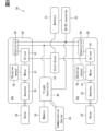
- FIG. 2 is a block diagram showing the electrical configuration of EDS in eVTOL; A perspective view of a rotor and an EDS unit. A perspective view of an EDS.
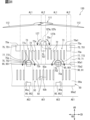
- FIG. 10 is a partially developed view of the outer peripheral surfaces of the motor and the inverter in Modification 1-1;
- FIG. 11 is a partially expanded view of the outer peripheral surfaces of the motor and the inverter in modification 1-2;
- FIG. 10 is a partially developed view of the outer peripheral surfaces of the motor and the inverter in Modification 1-1;
- FIG. 11 is a partially expanded view of the outer peripheral surfaces of the motor and the inverter in modification 1-2;
- FIG. 11 is a partially expanded view of the outer peripheral surfaces of the motor and the inverter in modification 1-3;
- FIG. 10 is a partially expanded view of the outer peripheral surfaces of the motor and the inverter in modification 1-4;
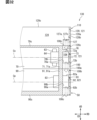
- FIG. 11 is a partial vertical cross-sectional view of a motor and an inverter in modification 1-5; The figure which expanded
- FIG. 11 is a partially developed view of the outer peripheral surfaces of the motor and the inverter in modification 2-1; The figure which expanded
- FIG. 20 is an enlarged view of the periphery of the exposed guide plate in FIG. 20; Partial longitudinal sectional view of a motor and an inverter.
- FIG. 20 is an enlarged view of the periphery of the high heat induction plate in FIG.
- FIG. 12 is an enlarged view of the periphery of the exposed guide plate in modification 5-1;
- FIG. 20 is an enlarged view of the periphery of the exposed guide plate in modification 5-1;
- FIG. 12 is an enlarged view of the periphery of the high heat induction plate in modification 5-2;
- FIG. 12 is a partially expanded view of the outer peripheral surfaces of the motor and the inverter in modification 5-3;
- FIG. 12 is an enlarged view of the periphery of the exposed guide plate in modification 5-4;
- FIG. 28 is an enlarged view of the periphery of the exposed guide plate in FIG. 28 ; Partial longitudinal sectional view of a motor and an inverter.
- FIG. 11 is a partially developed view of the outer peripheral surfaces of the motor and the inverter in modification 5-5;
- FIG. 12 is a partially developed view of the outer peripheral surfaces of the motor and the inverter in modification 5-6;
- a drive system 30 shown in FIG. 1 is mounted on the eVTOL 10 .
- the eVTOL 10 is an electric vertical takeoff and landing aircraft, and can take off and land vertically.
- eVTOL is an abbreviation for electric Vertical Take-Off and Landing aircraft.
- the eVTOL 10 is an aircraft that flies in the atmosphere and corresponds to an aircraft.
- the eVTOL 10 is a manned aircraft with a crew on board.
- the drive system 30 is a system that drives the eVTOL 10 to fly.
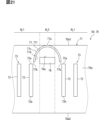
- the eVTOL 10 has a fuselage 11 and a rotor 20.
- the fuselage 11 has a fuselage body 12 and wings 13 .
- the fuselage body 12 is the body of the fuselage 11, and has a shape extending forward and backward, for example.
- the fuselage body 12 has a passenger compartment in which a passenger rides.
- the wings 13 extend from the fuselage body 12 and are provided in plurality on the fuselage body 12 .
- Wing 13 is a fixed wing.
- the multiple wings 13 include main wings, tail wings, and the like.
- a plurality of rotors 20 shown in FIGS. 1 and 3 are provided on the airframe 11 .
- the rotors 20 are provided on each of the fuselage body 12 and the wings 13 .
- the rotor 20 rotates around a motor axis Cm, which will be described later.
- the rotation axis of the rotor 20 is the motor axis Cm.
- Motor axis Cm coincides with the centerline of rotor 20 . If the direction in which the motor axis Cm extends is called the axial direction AD, the axial direction AD, the radial direction RD, and the circumferential direction CD of the motor axis Cm are orthogonal to each other.
- the rotor 20 rotates in the circumferential direction CD.
- the outer side in the radial direction RD may be referred to as the radial outer side
- the inner side in the radial direction RD may be referred to as the radial inner side.
- the rotor 20 has blades 21 , a rotor head 22 and a rotor shaft 23 .
- a plurality of blades 21 are arranged in the circumferential direction CD.
- the rotor head 22 connects multiple blades 21 .
- the blades 21 extend from the rotor head 22 in the radial direction RD.
- the blades 21 are vanes that rotate together with the rotor shaft 23 .
- the rotor shaft 23 is the rotating shaft of the rotor 20 and extends from the rotor head 22 along the motor axis Cm.
- the eVTOL10 is a tilt rotor machine.
- the eVTOL 10 allows the rotor 20 to be tilted. That is, the tilt angle of the rotor 20 is adjustable.
- the orientation of the rotor 20 is set such that the motor axis Cm extends vertically.
- rotor 20 functions as a lift rotor for generating lift in eVTOL 10 . That is, the rotor 20 can serve as a rotating blade.
- the orientation of the rotor 20 is set so that the motor axis Cm extends in the front-rear direction. In this case, rotor 20 functions as a cruising rotor for generating thrust in eVTOL 10 .
- the wing 13 can be tilted relative to the fuselage body 12. That is, it is possible to tilt the rotor 20 together with the blades 13 .
- the tilt angle of the rotor 20 is adjusted by adjusting the inclination angle of the wing 13 with respect to the airframe body 12 .
- the eVTOL 10 may allow the rotor 20 to tilt relative to the fuselage 11 .
- the tilt angle of the rotor 20 may be adjusted by adjusting the tilt angle of the rotor 20 relative to the blades 13 .
- the drive system 30 has a battery 31, a distributor 32, a converter 33, a communication device 34, a storage device 35, a flight control device 40, and an EDS 50.
- FIG. 2 shows the rotor 20 as Rotor, the battery 31 as Battery, the distributor 32 as Distributor, and the converter 33 as DC-DC converter.
- the communication device 34 is illustrated as Communication Device, the storage device 35 as Memory, and the flight control device 40 as Flight Controller.
- the battery 31 is electrically connected to multiple EDSs 50 .
- the battery 31 is a power supply unit that supplies power to the EDS 50 and corresponds to a power supply unit.
- a battery 31 is a DC voltage source that applies a DC voltage to the EDS 50 .
- the battery 31 has a rechargeable secondary battery.
- Such secondary batteries include lithium-ion batteries, nickel-metal hydride batteries, and the like.
- As the power supply unit in addition to or instead of the battery 31, a fuel cell, a generator, or the like may be used.
- the distributor 32 is electrically connected to the battery 31 and multiple EDSs 50 .
- the distributor 32 distributes power from the battery 31 to the multiple EDSs 50 .
- a driving section 81 (to be described later) is electrically connected to the distributor 32 . Electric power from the battery 31 is supplied to the drive unit 81 via the distributor 32 . If the voltage of the battery 31 is referred to as a high voltage, a high voltage is applied to the drive section 81 .
- the distributor 32 may be omitted as long as the power of the battery 31 is supplied to a plurality of EDSs 50 . As a configuration that does not require the distributor 32, for example, there is a configuration in which each of the plurality of EDSs 50 is individually provided with a power supply unit.
- the flight control device 40 is an ECU, for example, and controls the driving of the EDS 50.
- ECU is an abbreviation for Electronic Control Unit.
- the flight control device 40 is mainly composed of a microcomputer having, for example, a processor, memory, I/O, and a bus connecting them.
- a microcomputer is sometimes called a microcomputer.
- a memory is a non-transitory physical storage medium that non-temporarily stores computer-readable programs and data.
- a non-transitory tangible storage medium is a non-transitory tangible storage medium, which is realized by a semiconductor memory, a magnetic disk, or the like.
- the flight control device 40 is electrically connected to the storage device 35 and the EDS 50.
- the flight control device 40 executes a control program stored in at least one of the memory and the storage device 35 to execute various processes related to driving the EDS 50 .
- the flight control device 40 performs flight control for causing the eVTOL 10 to fly.
- This flight control includes control of the EDS 50, tilt angle control for changing the tilt angle of the rotor 20, and the like.
- a later-described drive control section 54 is electrically connected to the flight control device 40 .
- the flight control device 40 controls the EDS 50 by outputting a control signal to the drive control section 54 .
- the converter 33 is electrically connected to the battery 31, the flight control device 40 and the EDS 50.
- drive control section 54 is electrically connected to converter 33 .
- the converter 33 steps down or steps up the electric power from the battery 31 and supplies it to the flight control device 40 and the drive control section 54 . If the voltage of the power stepped down by the converter 33 is referred to as a low voltage, the low voltage is applied to the flight control device 40 and the drive control section 54 . This low voltage is a voltage lower than the voltage of the battery 31 . Conversely, if the voltage of the electric power boosted by the converter 33 is called a high voltage, the high voltage is applied to the flight control device 40 and the drive control section 54 . This high voltage is a voltage higher than the voltage of the battery 31 .
- the EDS 50 is a device that drives to rotate the rotor 20 and corresponds to a drive device.
- the EDS 50 is rotationally driven with respect to the rotor 20 .
- EDS50 is an abbreviation for Electric Drive System.
- the EDS 50 is sometimes referred to as an electric drive and an EPU.
- EPU is an abbreviation for Electric Propulsion Unit.
- the EDS 50 is individually provided for each of the multiple rotors 20 .
- the EDS 50 is aligned with the rotor 20 along the motor axis Cm. All of the multiple EDSs 50 are fixed to the fuselage 11 .
- EDS 50 rotatably supports rotor 20 .
- EDS 50 is mechanically connected to rotor shaft 23 .
- the plurality of EDSs 50 include at least one of the EDS 50 fixed to the body 11 in a state protruding outside the body 11 and the EDS 50 fixed to the body 11 in a state embedded inside the body 11. .
- the rotor 20 is fixed to the airframe 11 via the EDS 50.
- the EDS 50 is designed not to tilt relative to the rotor 20 .
- the EDS 50 can tilt relative to the airframe 11 together with the rotor 20 .
- the orientation of EDS 50 is set along with rotor 20 .
- the EDS 50 has a gearbox 53, a drive control section 54, a rotation sensor 55, a motor 61, and a drive section 81.
- the gearbox 53 is shown as Gearbox
- the drive unit 81 as Driver
- the drive control unit 54 as Controller
- the rotation sensor 55 as Rotation sensor
- the motor 61 as Motor.
- the motor 61 is a multi-phase AC motor, such as a three-phase AC rotary electric machine.
- the motor 61 functions as an electric motor that is the flight drive source of the eVTOL 10 .
- the motor 61 has a rotor and a stator.
- the motor 61 is electrically connected to the driving section 81 . Electric power is supplied to the motor 61 from the battery 31 through the drive unit 81 .
- the motor 61 is driven according to voltage and current supplied from the driving section 81 .
- a brushless motor for example, is used as the motor 61 .
- As the motor 61 an induction motor or a reactance motor may be used.
- the gearbox 53 mechanically connects the motor 61 and the rotor 20 .
- the rotor shaft 23 is mechanically connected to the rotating shaft of the motor 61 via the gearbox 53 .
- the gearbox 53 reduces the speed of rotation of the motor 61 and transmits it to the rotor 20 .
- the gearbox 53 is configured including a plurality of gears, and is sometimes called a transmission gear and a speed reducer.
- the gearbox 53 has a structure adapted to the motor characteristics of the motor 61 .
- the drive unit 81 drives the motor 61 by converting electric power supplied to the motor 61 .
- the drive unit 81 has an inverter.
- the inverter converts the power supplied to the motor 61 from direct current to alternating current.
- An inverter is a power converter that converts power.
- the inverter is a multiple-phase inverter, and performs power conversion for each of the multiple phases.
- the inverter is, for example, a three-phase inverter.
- the inverter is an inverter circuit including a plurality of switching elements.
- the switching elements include power elements such as IGBTs and MOSFETs.
- IGBT is an abbreviation for Insulated Gate Bipolar Transistor.
- MOSFET is an abbreviation for Metal-Oxide-Semiconductor Field-Effect Transistor.
- a switching element is sometimes referred to as a driving element.
- switching elements are connected in parallel in each of the multiple phases.
- the motor 61 is a three-phase AC motor
- a plurality of switching elements are connected in parallel to the motor 61 in each of the U-phase, V-phase, and W-phase.
- the plurality of switching elements may not be connected in parallel in each of the plurality of phases.
- a plurality of switching elements may not be connected in parallel to the motor 61 in each of the U-phase, V-phase, and W-phase.
- the rotation sensor 55 is provided for the motor 61.
- the rotation sensor 55 is a rotation detector that detects the rotation speed and rotation angle of the motor 61 .
- the rotation sensor 55 outputs a detection signal corresponding to the rotation speed of the motor 61 to the drive control section 54 .
- the rotation sensor 55 includes, for example, an encoder and a resolver.
- the drive control unit 54 is an ECU, for example, and controls the drive unit 81 .
- the drive control unit 54 is mainly composed of a microcomputer having, for example, a processor, memory, I/O, and a bus connecting them.
- the drive control section 54 is electrically connected to the flight control device 40 and the drive section 81 .
- the drive control unit 54 is electrically connected to various sensors including the rotation sensor 55 .
- the drive control unit 54 controls the drive unit 81 by outputting command signals to the drive unit 81 .
- the drive control unit 54 generates command signals according to control signals input from the flight control device 40, detection signals input from various sensors such as the rotation sensor 55, and the like.
- the inverter drives according to the command signal input from the drive control unit 54, and power conversion is performed by the inverter.
- Various sensors include, in addition to the rotation sensor 55, a current sensor and a voltage sensor.
- the current sensor detects, for example, the current flowing through the motor 61 for each of multiple phases.
- the voltage sensor detects voltage output from the battery 31, for example.
- the rotor 20 and the EDS 50 are arranged along the motor axis Cm.
- the rotor 20 rotates to send air to one side in the axial direction AD, thereby generating thrust and lift in the eVTOL 10 .
- the rotor 20 sends air toward the EDS 50 side in the axial direction AD.
- a swirling flow is generated along the motor axis Cm. In this swirling flow, the air flows in the axial direction AD while swirling in the circumferential direction CD.
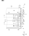
- the EDS 50 has a motor device 60, an inverter device 80 and a fin cover 100.
- the motor device 60 has a motor 61 and a motor housing 70 .
- Motor housing 70 accommodates motor 61 .
- the motor 61 has a motor shaft 62 .
- the motor shaft 62 is the rotating shaft of the motor 61 and rotates together with the rotor. If the rotation of the rotor is referred to as the rotation of the motor 61, the motor 61 rotates around the motor axis Cm.
- a motor axis Cm is a virtual line extending linearly and coincides with the center line of the motor 61 .
- the motor shaft 62 extends along the motor axis Cm.
- the inverter device 80 has a drive section 81 and an inverter housing 90 .
- Inverter housing 90 accommodates drive unit 81 .
- Motor device 60 and inverter device 80 are arranged along motor axis Cm.
- the motor housing 70 and the inverter housing 90 are arranged along the motor axis Cm.
- the motor housing 70 and the inverter housing 90 are formed in a tubular shape as a whole and extend along the motor axis Cm.
- the motor housing 70 and the inverter housing 90 are stacked on each other in the axial direction AD.
- the motor housing 70 and the inverter housing 90 are fixed to each other by fasteners such as bolts.
- the motor housing 70 and the inverter housing 90 are made of metal material or the like, and have thermal conductivity.
- the motor housing 70 and the inverter housing 90 constitute the housing of the EDS 50.
- the motor 61 and the driving section 81 are driven to rotate the rotor 20, and the driving tends to generate heat.
- the motor 61 and the driving section 81 correspond to the heating element, and the motor housing 70 and the inverter housing 90 correspond to the housing.
- the outer peripheral surface 70a of the motor housing 70 and the outer peripheral surface 90a of the inverter housing 90 correspond to the outer peripheral surface of the housing.
- These outer peripheral surfaces 70a and 90a are arranged in the axial direction AD.
- the outer peripheral surfaces 70a and 90a form a continuous surface extending continuously in the axial direction AD.
- the fin cover 100 accommodates the motor housing 70 and the inverter housing 90.
- the fin cover 100 has a tubular shape as a whole and extends along the motor axis Cm.
- the fin cover 100 spans over the motor housing 70 and the inverter housing 90 in the axial direction AD.
- the fin cover 100 covers the motor housing 70 and the inverter housing 90 from the outer peripheral side.
- the fin cover 100 is provided outside the motor housing 70 and the inverter housing 90 in the radial direction RD and extends along the outer peripheral surfaces 70a, 90a.
- the fin cover 100 is sometimes called a duct.
- the fin cover 100 is made of a resin material or the like and is elastically deformable.
- the fin cover 100 is attached to the motor housing 70 and the inverter housing 90 in an elastically deformed state.
- the fin cover 100 extends at least radially outward due to elastic deformation, and is held in position relative to the motor housing 70 and the inverter housing 90 by a restoring force directed radially inward.
- the fin cover 100 is attached to the motor housing 70 and the inverter housing 90 using the restoring force due to elastic deformation.
- the fin cover 100 corresponds to a housing cover.
- the thermal conductivity of the fin cover 100 is lower than that of the motor housing 70 and inverter housing 90 .
- a blower device 110 is attached to the EDS 50 .
- the blower device 110 is attached to the EDS 50 and constitutes an EDS unit 130 together with the EDS 50 .
- EDS unit 130 is mounted on eVTOL 10 .
- the blower device 110 is arranged along the motor axis Cm with respect to the rotor 20 and the EDS 50 .
- the blower device 110 is provided between the rotor 20 and the EDS 50 in the axial direction AD.
- the EDS unit 130 corresponds to the drive unit.
- the air blower 110 sends air by driving.
- the blower device 110 has a blower fan 111 and a shroud 120 .
- the blower fan 111 rotates around the motor axis Cm.
- the rotation axis of the blower fan 111 is the motor axis Cm.
- the centerline of the blower fan 111 coincides with the motor axis Cm.
- the blower fan 111 sends air toward the EDS 50 in the axial direction AD by rotating.
- Blower fan 111 sends cooling air toward EDS 50 for cooling EDS 50 .
- the side of the blower fan 111 is the upstream side of the EDS 50 .
- both the swirling flow caused by the blower fan 111 and the swirling flow caused by the rotor 20 are clockwise swirling flows that advance while swirling clockwise.
- the blower fan 111 has fan blades 112 and a fan shaft 113 .
- a plurality of fan blades 112 are arranged in the circumferential direction CD. Fan blades 112 are connected by a fan head. Fan blades 112 extend radially RD from the fan head. Fan blades 112 are blades that rotate together with fan shaft 113 .
- the fan shaft 113 is the rotating shaft of the blower fan 111 and extends from the fan head along the motor axis Cm.
- the shroud 120 houses the blower fan 111.
- Shroud 120 is formed in a tubular shape and extends along motor axis Cm.
- the shroud 120 is provided outside the blower fan 111 in the radial direction RD.
- Shroud 120 is attached to EDS 50 .
- the shroud 120 is fixed to the motor housing 70, for example.
- the shroud 120 is made of a resin material or the like.
- Shroud 120 has a lower thermal conductivity than motor housing 70 and inverter housing 90 .
- the motor shaft 62 is connected to the rotor 20 and the blower fan 111.
- the rotor shaft 23 and the fan shaft 113 are connected to the motor shaft 62 .
- the motor shaft 62 is connected to the rotor 20 via the gearbox 53, but the illustration of the gearbox 53 is omitted in FIGS. Note that the motor shaft 62 may be connected to the rotor 20 without the gearbox 53 interposed therebetween. Also, the motor shaft 62 may be integrated with the fan shaft 113 .
- air sent by the rotor 20 and the blower fan 111 flows along the outer peripheral surfaces 70a and 90a.
- the amount of heat released from the motor housing 70 and the inverter housing 90 to the air tends to increase.
- the heat generated from the motor 61, the drive unit 81, etc. is easily released to the outside through the motor housing 70 and the inverter housing 90.
- the gas that flows along the outer peripheral surfaces 70a and 90a does not have to be air as long as it can exchange heat with the motor housing 70 and the inverter housing 90 .
- both the blower fan 111 and the rotor 20 correspond to fans.
- the axial direction AD is the upstream/downstream direction in which air flows.
- the blower fan 111 is upstream of the EDS 50 .
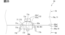
- the motor housing 70 has an outer peripheral surface 70a, an inner peripheral surface 70b (see FIG. 7) and an upstream end surface 70c.
- the outer peripheral surface 70a and the inner peripheral surface 70b extend in the axial direction AD along the motor axis Cm and annularly extend in the circumferential direction CD.
- the upstream end face 70c is the end face of the motor housing 70 and faces the blower fan 111 side.
- the upstream end face 70c extends in a direction perpendicular to the axial direction AD.
- the outer peripheral surface 70a includes an outer peripheral upstream end 70a1 and an outer peripheral downstream end 70a2.
- the outer peripheral upstream end 70a1 is the upstream end of the outer peripheral surface 70a and extends along the outer peripheral edge of the upstream end surface 70c.
- the outer peripheral downstream end 70a2 is the downstream end of the outer peripheral surface 70a.
- the motor housing 70 has a housing body 71, motor fins 72 and flanges 75.
- the housing main body 71 is formed in a cylindrical shape as a whole and extends along the motor axis Cm.
- the housing body 71 forms an outer peripheral surface 70a, an inner peripheral surface 70b and an upstream end surface 70c.
- the motor fins 72 are fins provided on the outer peripheral surface 70a.
- the motor fins 72 can radiate the heat of the motor device 60 to the outside, and correspond to radiation fins. By increasing the surface area of the motor housing 70 , the motor fins 72 enhance the heat radiation effect from the motor housing 70 .
- the motor fins 72 protrude from the outer peripheral surface 70a.
- the motor fins 72 are provided integrally with the housing body 71 .
- the motor fin 72 is formed in a plate shape.
- the motor fins 72 extend radially outward from the housing body 71 and extend in the axial direction AD.
- a radial line For example, if an imaginary straight line passing through the motor axis Cm and extending in the radial direction RD is called a radial line, the motor fins 72 extend in the radial direction RD so as to overlap the radial line.
- a plurality of motor fins 72 are arranged in the circumferential direction CD along the outer peripheral surface 70a.
- the plate surfaces of the two motor fins 72 adjacent in the circumferential direction CD face each other.
- the motor fin 72 is provided near the center of the outer peripheral surface 70a in the axial direction AD.
- the motor fin 72 is located on the outer peripheral surface 70a apart from both the outer peripheral upstream end 70a1 and the outer peripheral downstream end 70a2.
- the projection dimension of the motor fins 72 from the outer peripheral surface 70a is larger than the projection dimension of the flange 75 from the outer peripheral surface 70a.
- the motor fin 72 has a fin upstream end 72a and a fin downstream end 72b.
- the upstream end is the fin upstream end 72a
- the downstream end is the fin downstream end 72b.
- the flange 75 is provided on the outer peripheral surface 70a and protrudes from the outer peripheral surface 70a.
- the flange 75 extends radially outward from the housing body 71 .
- the width dimension of the flange 75 is larger than the plate thickness dimension of the motor fin 72 in the circumferential direction CD.
- Flange 75 has an upstream surface 75a.
- the upstream surface 75a is a surface of the outer surface of the flange 75 facing the upstream side.
- the upstream surface 75a extends in a direction perpendicular to the axial direction AD.
- the flange 75 tends to become an obstacle to the air flowing in the axial direction AD due to its large width and the fact that the upstream surface 75a is orthogonal to the axial direction AD.
- the flange 75 is likely to block the flow of air in the axial direction AD and corresponds to an obstruction.
- the flange 75 is, for example, a case fixing portion.
- the flange 75 is a part for fixing the motor housing 70 to fixed objects such as the inverter housing 90 and the shroud 120 .
- a fastener such as a bolt is screwed to the flange 75 .
- an upstream flange 751 and a downstream flange 752 are provided on the outer peripheral surface 70a.
- the upstream flange 751 is positioned closer to the outer peripheral upstream end 70a1 on the outer peripheral surface 70a.
- the upstream flange 751 extends, for example, in the axial direction AD from the outer peripheral upstream end 70a1 toward the outer peripheral downstream end 70a2.
- the downstream flange 752 is positioned closer to the outer peripheral downstream end 70a2 on the outer peripheral surface 70a.
- the downstream flange 752 extends, for example, from the outer peripheral downstream end 70a2 toward the outer peripheral upstream end 70a1.
- a plurality of upstream flanges 751 and downstream flanges 752 are arranged in the circumferential direction CD along the outer peripheral surface 70a.
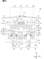
- the outer peripheral surface 70a has an exposed area AL1 and a hidden area AL2.
- Hidden area AL2 is an area hidden behind flange 75 for blower fan 111 .
- the area hidden from the blower fan 111 on the downstream side of the upstream flange 751 is the hidden area AL2.
- This hidden area AL2 extends downstream from the upstream flange 751 in the axial direction AD.
- the hidden area AL2 is on the opposite side of the blower fan 111 via the flange 75 in the axial direction AD.
- a plurality of hidden areas AL2 are arranged in the circumferential direction CD together with the upstream flange 751 .
- the exposed area AL1 is an area exposed to the blower fan 111 without being hidden behind the flange 75 .
- an exposed area that is not hidden downstream of the upstream flange 751 is the exposed area AL1.
- the exposed area AL1 is an area aligned with the hidden area AL2 in the circumferential direction CD.
- the exposed area AL1 spans two hidden areas AL2 adjacent to each other in the circumferential direction CD.
- a plurality of exposed areas AL1 are arranged in the circumferential direction CD together with hidden areas AL2.
- the exposed area AL1 corresponds to the axial alignment area
- the hidden area AL2 corresponds to the peripheral alignment area
- the upstream flange 751 corresponds to the obstruction.
- the motor fin 72 is provided in the exposed area AL1, but is not provided in the hidden area AL2.
- a plurality of motor fins 72 are provided in each of the plurality of exposed areas AL1.
- a plurality of motor fins 72 provided in one exposed area AL1 are called a motor fin group 73
- one motor fin group 73 is provided in one exposed area AL1.
- a plurality of motor fin groups 73 are arranged in the circumferential direction CD together with the exposed area AL1.
- a hidden area AL2 exists between two adjacent motor fin groups 73 in the circumferential direction CD.
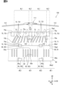
- forwardly inclined fins 721 are provided on the outer peripheral surface 70a.
- the forward inclined fins 721 are inclined in the circumferential direction CD with respect to the motor axis Cm.
- the forward inclined fin 721 extends straight in a direction inclined in the circumferential direction CD with respect to the motor axis Cm. All portions of the forwardly inclined fin 721, including the upstream portion extending downstream from the fin upstream end 72a, are inclined in the circumferential direction CD with respect to the motor axis Cm.
- the forwardly inclined fin 721 as a whole is the inclined portion in this embodiment.
- the inclination angle of the forwardly inclined fins 721 is such that the forwardly inclined fins 721 extend along the swirling flow from the blower fan 111 .
- one of the pair of plate surfaces faces the upstream side, and the other faces the downstream side.
- Both of the pair of plate surfaces of the forwardly inclined fin 721 are flat surfaces. That is, the plate surface of the forwardly inclined fin 721 has a flat shape.
- the fin upstream end 72a and the fin downstream end 72b are at positions shifted in the circumferential direction CD.
- the forward inclined fin 721 is inclined so as to extend along the swirl flow by the blower fan 111 .
- the plate surface of the forward-slanted fin 721 extends along the swirling flow.
- the plate surface of the forwardly inclined fin 721 is non-parallel to the motor axis Cm. That is, in the forward inclined fin 721, the plate surface is inclined with respect to the motor axis Cm.
- the fin downstream end 72b is located downstream of the fin upstream end 72a in the circumferential direction CD.
- the forward oblique fins 721 correspond to heat radiation fins and oblique fins.
- a plurality of forwardly inclined fins 721 are arranged in the circumferential direction CD in each of the plurality of exposed areas AL1.
- the plurality of forward oblique fins 721 have the same size and shape.
- the length dimension in the axial direction AD, the plate thickness dimension, and the projection dimension from the outer peripheral surface 70a are the same for the plurality of forward-slanted fins 721 .
- the inclination angles with respect to the motor axis Cm are the same for the plurality of forwardly inclined fins 721 .
- the inclination angle of the forward inclined fins 721 is, for example, 5 degrees to 45 degrees.
- the plurality of forward-slanted fins 721 extend parallel to each other.
- the plurality of forwardly inclined fins 721 are arranged at regular intervals in the circumferential direction CD.
- each forward oblique fin 721 has the same size and shape.
- the inclination angles of the forwardly inclined fins 721 with respect to the motor axis Cm are also the same in the plurality of exposed areas AL1.
- the intervals between the plurality of forward-slanted fins 721 are also the same in the plurality of exposed regions AL1.
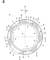
- the motor housing 70 accommodates the coil 63 and the coil support portion 64 .
- the coil 63 and the coil support portion 64 are included in the motor 61 and are one of the components that make up the motor 61 .
- the coil 63 and the coil support portion 64 are likely to generate heat as the motor 61 is driven.
- the coil 63 and the coil support portion 64 correspond to heat generating members.
- a coil 63 is a winding that constitutes the motor 61 .
- the coil 63 is formed in an annular shape as a whole and extends inside the motor housing 70 along the inner peripheral surface 70b.
- the coil support portion 64 is fixed to the motor housing 70 and supports the coil 63 .
- a plurality of coil support portions 64 are arranged in the circumferential direction CD along the inner peripheral surface 70b.
- the coil support portion 64 is attached to the inner peripheral surface 70b.
- the coil support portion 64 is made of a resin material or the like.
- the motor fin 72 is provided at a position aligned with the coil 63 in the radial direction RD. At least a portion of the motor fin 72 is positioned to overlap the coil 63 in the axial direction AD in the radial direction RD. The motor fin 72 is located at a position through which the coil centerline Cc passes.
- the coil centerline Cc is an imaginary straight line passing through the center of the coil 63 and extending in the radial direction RD.
- the motor fin 72 is arranged such that the coil centerline Cc passes through the center of the motor fin 72 .
- an overlapping region overlapping the coil 63 in the radial direction RD of the outer peripheral surface 70a extends annularly in the circumferential direction CD.
- This overlapping area is an area where heat from the coil 63, which is a heat generating member, is easily transmitted. That is, this overlapping area is an area corresponding to a high heat area AE1, which will be described later.
- one high heat area AE1 is configured to encircle the outer peripheral surface 70a in the circumferential direction CD.
- the inverter housing 90 has an outer peripheral surface 90a, an inner peripheral surface 90b (see FIGS. 6 and 7), and a downstream end surface 90c.
- the outer peripheral surface 90a and the inner peripheral surface 90b extend in the axial direction AD along the motor axis Cm and annularly extend in the circumferential direction CD.
- the downstream end face 90 c is the end face of the inverter housing 90 and faces the side opposite to the blower fan 111 .
- the downstream end face 90c extends in a direction perpendicular to the axial direction AD.
- the outer peripheral surface 90a includes an outer peripheral upstream end 90a1 and an outer peripheral downstream end 90a2.
- the outer peripheral upstream end 90a1 is the upstream end of the outer peripheral surface 90a.
- the outer peripheral downstream end 90a2 is the downstream end of the outer peripheral surface 90a and extends along the outer peripheral edge of the downstream end surface 90c.
- the inverter housing 90 has a housing body 91, inverter fins 92, flanges 95 and housing protrusions 96.
- the housing body 91 is formed in a tubular shape as a whole and extends along the motor axis Cm.
- the housing body 91 forms an outer peripheral surface 90a, an inner peripheral surface 90b and a downstream end surface 90c.
- the inverter fins 92 are fins provided on the outer peripheral surface 90a.
- the inverter fins 92 can release the heat of the inverter device 80 to the outside, and correspond to heat radiation fins.
- the inverter fins 92 enhance the heat radiation effect from the inverter housing 90 .
- the inverter fins 92 protrude from the outer peripheral surface 90a.
- the inverter fins 92 are provided integrally with the housing body 91 .
- the inverter fins 92 are formed in a plate shape.
- the inverter fins 92 extend radially outward from the housing body 91 and extend in the axial direction AD.
- the inverter fins 92 extend in the radial direction RD so as to overlap the radial line.
- a plurality of inverter fins 92 are arranged in the circumferential direction CD along the outer peripheral surface 90a. In two inverter fins 92 adjacent in the circumferential direction CD, their plate surfaces face each other.
- the inverter fins 92 are provided near the center of the outer peripheral surface 90a in the axial direction AD.
- the inverter fins 92 are positioned apart from both the outer peripheral upstream end 90a1 and the outer peripheral downstream end 90a2 on the outer peripheral surface 90a.
- the projection dimension of the inverter fins 92 from the outer peripheral surface 90a is larger than the projection dimension of the flange 95 from the outer peripheral surface 90a.
- the inverter fin 92 has a fin upstream end 92a and a fin downstream end 92b.
- the end on the blower fan 111 side is the fin upstream end 92a, and the opposite end is the fin downstream end 92b.
- the flange 95 is provided on the outer peripheral surface 90a and protrudes from the outer peripheral surface 90a.
- the flange 95 extends radially outward from the housing body 91 .
- the width dimension of the flange 95 is larger than the plate thickness dimension of the inverter fin 92 in the circumferential direction CD.
- Flange 95 has an upstream surface 95a.
- the upstream surface 95a is a surface of the outer surface of the flange 95 facing the blower fan 111 side.
- the upstream surface 95a extends in a direction perpendicular to the axial direction AD.
- the flange 95 tends to be an obstacle to the air flowing in the axial direction AD due to its large width and the fact that the upstream surface 95a is orthogonal to the axial direction AD.
- the flange 95 is likely to block the flow of air in the axial direction AD and corresponds to an obstruction.
- the flange 95 is, for example, a case fixing portion.
- the flange 95 is a part for fixing the inverter housing 90 to a fixed object such as the motor housing 70 .
- a fastener such as a bolt is screwed to the flange 95 .
- an upstream flange 951 and a downstream flange 952 are provided on the outer peripheral surface 90a.
- the upstream flange 951 is positioned closer to the outer peripheral upstream end 90a1 on the outer peripheral surface 90a.
- the upstream flange 951 extends, for example, in the axial direction AD from the outer peripheral upstream end 90a1 toward the outer peripheral downstream end 90a2.
- the downstream flange 952 is positioned closer to the outer peripheral downstream end 90a2 on the outer peripheral surface 90a.
- the downstream flange 952 extends, for example, from the outer peripheral downstream end 90a2 toward the outer peripheral upstream end 90a1.
- a plurality of upstream flanges 951 and downstream flanges 952 are arranged in the circumferential direction CD along the outer peripheral surface 90a.
- the housing protrusion 96 is a protrusion provided on the outer peripheral surface 90a.
- the housing protrusion 96 protrudes from the outer peripheral surface 90a.
- the housing projection 96 extends radially outward from the housing body 91 .
- the housing projecting portion 96 includes a portion projecting radially outward in accordance with the internal structure of the inverter housing 90, a connector portion for electrically connecting the inverter device 80 to an external device, and the like.
- the housing protrusion 96 shown in FIG. 6 is a large protrusion.
- a switch module 83 is accommodated in the inverter housing 90 .
- the switch module 83 is included in the drive section 81 and is one of the components that make up the drive section 81 .
- the switch module 83 tends to generate heat as the drive unit 81 is driven.
- the switch module 83 corresponds to a heat generating member.
- the switch module 83 has a switching element and an element protection section.
- a switching element is a semiconductor element that constitutes an inverter or the like.
- the element protection part is made of a resin material, and protects the switching element while covering it.
- the switch modules 83 are arranged inside the inverter housing 90 in the circumferential direction CD along the inner peripheral surface 90b. Each switch module 83 is attached to the inner peripheral surface 90b.
- a plurality of switch modules 83 are provided for a plurality of phases.
- a plurality of switch modules 83 are provided for each of the U-phase, V-phase, and W-phase.
- the switching elements of each of the plurality of switch modules 83 are connected in parallel.
- the outer peripheral surface 90a has a high heat area AE1 and a low heat area AE2.
- the high heat area AE1 is an area to which heat from the drive unit 81 is relatively easily imparted.
- the high heat area AE1 is an area that overlaps the switch module 83 in the radial direction RD.
- heat from switch module 83 is easily transferred to high heat area AE1 via housing body 71 .
- a plurality of high heat areas AE1 are arranged in the circumferential direction CD so as to match the positions of the switch modules 83 .
- the high heat area AE1 is an area bridging between the outer peripheral upstream end 90a1 and the outer peripheral downstream end 90a2 in the axial direction AD.
- the low heat area AE2 is an area to which heat from the drive unit 81 is less likely to be applied than the high heat area AE1.
- the low heat area AE2 is an area that does not overlap the switch module 83 in the radial direction RD.
- the low heat area AE2 is located farther from the switch module 83 than the high heat area AE1.
- the distance between the low heat area AE2 and the switch module 83 is smaller than the distance between the high heat area AE1 and the switch module 83 .
- the low heat area AE2 overlaps in the radial direction RD with the spaced area between two switch modules 83 adjacent in the circumferential direction CD. Heat from the switch module 83 is less likely to be transferred to the low heat area AE2 than to the high heat area AE1.
- the low heat area AE2 is located between two high heat areas AE1 adjacent to each other in the circumferential direction CD and is an area spanning these high heat areas AE1.
- a plurality of low heat areas AE2 are arranged in the circumferential direction CD.
- the low heat area AE2 is an area bridging between the outer peripheral upstream end 90a1 and the outer peripheral downstream end 90a2 in the axial direction AD.
- the low heat area AE2 is between two hidden areas AL2 adjacent in the circumferential direction CD.
- the low heat area AE2 is located at a distance in the circumferential direction CD from any of these hidden areas AL2.
- the low heat area AE2 is aligned with the exposed area AL1 in the axial direction AD and extends from the exposed area AL1 in the axial direction AD.
- the high heat area AE1 spans two adjacent exposed areas AL1 in the circumferential direction CD via the hidden area AL2.
- High heat area AE1 extends in axial direction AD from both exposed area AL1 and hidden area AL2.
- the high heat area AE1 corresponds to the first heat area
- the low heat area AE2 corresponds to the second heat area.
- a plurality of large switch modules 83 are arranged in the circumferential direction CD along the inner peripheral surface 90b.
- a plurality of switch module groups may be arranged in the circumferential direction CD along the inner peripheral surface 90b.
- the switch module group a plurality of small switch modules 83 are arranged.
- the high heat area AE1 is an area that overlaps one switch module group in the radial direction RD.
- a flange 95 is provided in the low heat area AE2.
- the flange 95 is located apart in the circumferential direction CD from both of the two high heat areas AE1 adjacent to each other in the circumferential direction CD.
- the high heat area AE1 is an area that dissipates heat more easily than the low heat area AE2.
- the inverter fins 92 are provided in the high heat area AE1, while the inverter fins 92 are not provided in the low heat area AE2.
- heat from the switch module 83 is easily radiated by the inverter fins 92 .
- the high heat area AE1 corresponds to the fin area
- the low heat area AE2 corresponds to the finless area.
- a plurality of inverter fins 92 are provided in each of the plurality of high heat areas AE1. If a plurality of inverter fins 92 provided in one high heat area AE1 are called an inverter fin group 93, one inverter fin group 93 is provided in one high heat area AE1. A plurality of inverter fin groups 93 are arranged in the circumferential direction CD together with the high heat area AE1. A low heat area AE2 exists between two adjacent inverter fin groups 93 in the circumferential direction CD. The inverter fins 92 overlap the switch module 83 in the radial direction RD with respect to the circumferential direction CD.
- parallel fins 923 are provided on the outer peripheral surface 90a.
- the parallel fins 923 extend parallel to the motor axis Cm.
- the parallel fins 923 are not inclined in the circumferential direction CD with respect to the motor axis Cm, but extend straight in the axial direction AD. Both of the pair of plate surfaces of the parallel fins 923 are flat surfaces.
- the parallel fins 923 correspond to heat radiation fins.
- a plurality of parallel fins 923 are arranged in the circumferential direction CD in each of the plurality of high heat areas AE1.
- the parallel fins 923 have the same size and shape.
- the length dimension in the axial direction AD, the plate thickness dimension, and the projection dimension from the outer peripheral surface 90a are the same for the plurality of parallel fins 923 .
- a plurality of parallel fins 923 extend parallel to each other. The plurality of parallel fins 923 are arranged at regular intervals in the circumferential direction CD.
- the parallel fins 923 have the same size and shape in the plurality of high heat areas AE1.
- the intervals between the parallel fins 923 are also the same in the high heat areas AE1.
- the inverter fins 92 are positioned to line up with the switch module 83 in the radial direction RD. At least a portion of the inverter fins 92 are positioned to overlap the switch module 83 in the axial direction AD in the radial direction RD.
- the inverter fin 92 is located at a position through which the module centerline Cp passes.
- the module centerline Cp is an imaginary straight line passing through the center of the switch module 83 and extending in the radial direction RD.
- the inverter fins 92 are arranged such that the module centerline Cp passes through the center of the inverter fins 92 .
- the inverter housing 90 also has an exposed area AL1 and a hidden area AL2 on the outer peripheral surface 90a.
- the hidden area AL ⁇ b>2 is an area hidden behind the upstream flange 951 for the blower fan 111 , for example.
- the exposed area AL1 is, for example, an area exposed to the blower fan 111 without being hidden behind the flange of the upstream flange 951 .
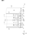
- the fin cover 100 has an outer peripheral surface 100a, an inner peripheral surface 100b and a cover opening 100c.
- the outer peripheral surface 100a and the inner peripheral surface 100b extend in the axial direction AD along the motor axis Cm and annularly extend in the circumferential direction CD.
- the cover openings 100c are provided at both ends of the fin cover 100 aligned in the axial direction AD.
- the inner peripheral surface 100b corresponds to the inner peripheral surface of the cover.
- the inner peripheral surface 100b of the fin cover 100 extends along the outer peripheral surfaces 70a, 90a while facing the outer peripheral surfaces 70a, 90a. Part or all of the motor fins 72 and the inverter fins 92 are in contact with the inner peripheral surface 100b. For example, the tip surfaces of the motor fins 72 and the inverter fins 92 overlap with the inner peripheral surface 100b.
- the inner peripheral surface 100b is pressed against the motor fins 72 and the inverter fins 92 by a restoring force due to elastic deformation.
- the restoring force of the fin cover 100 maintains the relative position of the fin cover 100 with respect to the motor housing 70 and the inverter housing 90 .
- FIG. 7 for convenience of illustration, gaps are shown between the inner peripheral surface 100b and the fins 72, 92, but in practice these gaps are less likely to occur.
- the shroud 120 has an outer peripheral surface 120a, an inner peripheral surface 120b and a shroud opening 120c.
- the outer peripheral surface 120a and the inner peripheral surface 120b extend in the axial direction AD along the motor axis Cm and annularly extend in the circumferential direction CD.
- the shroud openings 120c are provided at both ends of the shroud 120 aligned in the axial direction AD.
- An internal space 124 of the shroud 120 is opened in the axial direction AD by a shroud opening 120c.
- blower fan 111 is housed in internal space 124 .
- the shroud 120 and the fin cover 100 are arranged in the axial direction AD.
- the outer peripheral surfaces 100a, 120a are aligned in the axial direction AD
- the inner peripheral surfaces 100b, 120b are aligned in the axial direction AD.
- the inner peripheral surfaces 100b and 120b form a continuous surface extending continuously in the axial direction AD.
- the EDS 50 has a cover passage 104.
- a cover passage 104 is formed between the fin cover 100 and the motor housing 70 and the inverter housing 90 .
- the inner peripheral surface 100 b and the outer peripheral surfaces 70 a and 90 a are separated from each other via the motor fins 72 and the inverter fins 92 .
- This spaced portion serves as the cover passage 104 .
- the cover passage 104 is opened in the axial direction AD by a cover opening 100c.
- interior space 124 communicates with cover passage 104 .
- the hidden area AL2 closer to the fin downstream end 72b than to the fin upstream end 72a in the circumferential direction CD is referred to as the "forward hidden area.” AL2”.
- the swirling flow that has flowed along the forward inclined fins 721 easily flows into the “forward hidden area AL2”.
- the forwardly inclined fin 721 closest to the "forward hidden area AL2" in the exposed area AL1 guides the swirling flow to flow into the "forward hidden area AL2".
- the forward inclined fins 721 in the right exposed area AL1 guide the swirling flow into the "forward hidden area AL2".
- the high heat area AE1 closer to the fin downstream end 72b than the fin upstream end 72a in the circumferential direction CD is referred to as a "forward high heat area AE1".
- the swirling flow that has flowed along the forward inclined fins 721 easily flows into the "forward high heat area AE1".
- the forward inclined fin 721 in the exposed area AL1 is inclined in the circumferential direction CD with respect to the motor axis Cm so as to extend toward the "forward high heat area AE1", and the swirling flow is generated in the "forward high heat area AE1". It will guide you to flow into.
- the central high heat area AE1 is defined as a "forward high heat area AE1”
- the forward inclined fins 721 in the right exposed area AL1 guide the swirling flow into the "forward high heat area AE1".
- the swirling flow sent from the blower fan 111 circulates in the circumferential direction even after passing the forwardly slanted fins 721 due to the fact that the forwardly slanted fins 721 are slanted in the circumferential direction CD with respect to the motor axis Cm. It has become easier to continue On the other hand, since the parallel fins 923 extend parallel to the motor axis Cm, the swirling flow tends to become a parallel flow that travels parallel to the motor axis Cm by passing through the parallel fins 923 .
- the parallel fins 923 have a rectifying function of rectifying air flowing as a swirling flow so that it travels along the motor axis Cm. The swirl flow tends to become a parallel flow due to the straightening function of the parallel fins 923 .
- the parallel flow rectified by the parallel fins 923 is discharged to the outside from the cover passage 104 toward the downstream side as a parallel flow.
- forwardly inclined fins 721 inclined in the circumferential direction CD with respect to the motor axis Cm are provided on the outer peripheral surface 70a.
- the forwardly inclined fins 721 can guide the air flowing along the outer peripheral surface 70 a so as to enhance the cooling effect for the EDS 50 . Therefore, even if the number and size of the motor fins 72 and the inverter fins 92 are limited so that the EDS 50 does not become too heavy for the eVTOL 10, the downwardly inclined fins 721 can prevent the cooling effect of the EDS 50 from being lowered. . Therefore, both the improvement of the cooling effect and the weight reduction of the EDS 50 can be achieved by the forwardly inclined fins 721 . In this way, the EDS 50 and the EDS unit 130 suitable for mounting on the eVTOL 10 can be realized by the forward inclined fins 721 .
- the motor fins 72 in a configuration in which the motor fins 72 do not include the forwardly inclined fins 721, the motor fins 72 inclined so as to extend along the swirl flow by the blower fan 111 do not exist.
- the swirling flow that reaches the motor fins 72 is disturbed, and the pressure loss of the swirling flow flowing between the plurality of motor fins 72 increases. If the pressure loss increases in this way, there is concern that the amount of swirling air flowing between the motor fins 72 will be insufficient, and the heat dissipation effect of the motor fins 72 will be reduced.
- the amount of air flowing between the inverter fins 92 arranged downstream of the motor fins 72 is also reduced, and there is concern that the heat dissipation effect of the inverter fins 92 is also reduced.
- the forwardly inclined fins 721 are inclined so as to extend along the swirling flow generated by the blower fan 111 .
- the forwardly inclined fins 721 can guide the swirling flow so that the swirling flow is not disturbed. Therefore, the swirling flow reaching the forwardly inclined fins 721 is less likely to be disturbed.
- the pressure loss of the swirling flow flowing between the plurality of forwardly inclined fins 721 is less likely to increase, and the shortage of air volume of the swirling flow flowing between the plurality of forwardly inclined fins 721 is less likely to occur. Therefore, the air volume of the swirl flow flowing between the plurality of forwardly inclined fins 721 can be sufficiently secured for cooling the motor device 60 . In this manner, the heat dissipation effect of the forwardly inclined fins 721 can be enhanced.
- the fin cover 100 is attached to the motor housing 70 and the inverter housing 90 so as to cover the motor fins 72 and the inverter fins 92 from the outer peripheral side.
- the swirling flow generated by the blower fan 111 flows through the cover passage 104 formed between the motor housing 70 and the inverter housing 90 and the fin cover 100 . Therefore, the fin cover 100 can prevent the swirling flow from flowing radially outside the motor fins 72 and the inverter fins 92 . Therefore, the fin cover 100 can prevent the amount of air passing through the motor fins 72 and the inverter fins 92 from decreasing and the cooling effect from decreasing.
- the forwardly inclined fins 721 suppress an increase in the pressure loss of the swirling flow. Therefore, even if the pressure loss in the cover passage 104 increases, the forwardly inclined fins 721 suppress the increase in the pressure loss, so that the pressure loss does not excessively increase.
- the swirling flow generated by the blower fan 111 is not guided in the circumferential direction CD and is less likely to flow into the hidden area AL2.
- the swirling flow tends to flow into the exposed area AL1 but less likely to flow into the hidden area AL2.
- the air volume in the hidden area AL2 tends to be smaller than the air volume in the exposed area AL1.
- the heat generation mode tends to be uniform in the circumferential direction CD due to the fact that the coil 63 as the heat generating member extends annularly in the circumferential direction CD.
- the heat dissipation effect tends to be lower in the hidden area AL2 than in the exposed area AL1. tend to be uniform.
- the forwardly inclined fins 721 are inclined so as to guide the swirling flow from the exposed area AL1 to the hidden area AL2.
- the swirling flow that has flowed into the exposed area AL1 flows along the forwardly inclined fins 721, thereby making it easier to flow into the hidden area AL2. Therefore, it is difficult for the air volume in the hidden area AL2 to be less than the air volume in the exposed area AL1. Therefore, it is possible to prevent uneven heat distribution in the circumferential direction CD in the motor housing 70 .
- a cooling effect can be applied to the entire circumferential direction CD in the motor housing 70 .
- the forwardly inclined fins 721 are inclined so as to guide the swirling flow to the high heat area AE1.
- the swirling flow flows along the forward-slanted fins 721, making it easier to flow into the high heat area AE1, so that the high heat area AE1 tends to increase. Therefore, in the high heat area AE1, which is the area near the switch module 83 out of the high heat area AE1 and the low heat area AE2, the downwardly inclined fins 721 can prevent the cooling effect from deteriorating due to insufficient air volume. Therefore, in the inverter housing 90, the forwardly inclined fins 721 can prevent the temperature of a part such as the high heat area AE1 from excessively rising.
- the forward-slanted fin 721 is provided at a position separated from the high heat area AE1 on the upstream side of the swirling flow, and is slanted so as to extend into the high heat area AE1. Therefore, both a configuration in which the swirling flow easily flows along the forwardly inclined fins 721 and a configuration in which the swirling flow flowing along the forwardly inclined fins 721 easily reaches the high heat area AE1 can be realized.
- the high heat area AE1 is an area that overlaps the switch module 83 in the circumferential direction CD
- the low heat area AE2 is an area that does not overlap the switch module 83 in the circumferential direction CD.
- the heat applied to the low heat area AE2 tends to be less than the heat applied to the high heat area AE1. Therefore, by guiding the swirling flow to the high heat area AE1 with the forwardly inclined fins 721, even if the air volume in the low heat area AE2 decreases, the temperature in the low heat area AE2 is unlikely to rise excessively. there is Therefore, even if the air volume in the low heat area AE2 is less than the air volume in the high heat area AE1, the inverter housing 90 can enhance the cooling effect in the entire circumferential direction CD.
- the inverter fins 92 are provided in the high heat area AE1, while the inverter fins 92 are not provided in the low heat area AE2.
- the upstream portion extending downstream from the fin upstream end 72a is inclined with respect to the motor axis Cm.
- the swirling flow that reaches the forwardly inclined fins 721 easily flows along the upstream portion of the forwardly inclined fins 721 . Therefore, the upstream portion of the forwardly inclined fin 721 can suppress the disturbance of the swirling flow that has reached the forwardly inclined fin 721 . Therefore, an increase in the pressure loss of the swirling flow flowing between the forwardly slanted fins 721 can be suppressed by the upstream portion of the forwardly slanted fins 721 .
- the parallel fins 923 are provided downstream of the forwardly inclined fins 721 .
- the swirling flow is easily rectified by the parallel fins 923 to become a parallel flow.
- the parallel flow of the air discharged downstream from the EDS 50 makes it difficult for the thrust and lift generated by the eVTOL 10 to decrease.
- the component flowing in the circumferential direction CD tends to be smaller than when it is a swirl flow.
- the EDS 50 suitable for mounting on the eVTOL 10 can be realized from the viewpoint of properly managing the flight state of the eVTOL 10 as well.
- the tip surfaces of the motor fins 72 and the inverter fins 92 overlap the inner peripheral surface 100b. Therefore, the air from the blower fan 111 easily flows along the plate surfaces of the motor fins 72 and the inverter fins 92 . Therefore, the cooling effect exhibited by the motor fins 72 and the inverter fins 92 can be further enhanced.
- Radiation fins such as the motor fins 72 may be provided in the hidden area AL2.
- Radiation fins such as the motor fins 72 may be provided in the hidden area AL2.
- the forward oblique fin 721 is provided in the hidden area AL2.
- a forward inclined fin 721 is provided in each of the exposed area AL1 and the hidden area AL2.
- One of the forwardly inclined fins 721 out of the plurality of forwardly inclined fins 721 is in a state of bridging between the exposed area AL1 and the hidden area AL2.
- the forwardly inclined fin 721 is arranged at a position straddling the boundary between the exposed area AL1 and the hidden area AL2 in the circumferential direction CD.
- the fin upstream end 72a is located in the exposed area AL1
- the fin downstream end 72b is located in the hidden area AL2.
- the fin downstream end 72b is located on the opposite side of the blower fan 111 via the upstream flange 751 in the axial direction AD.
- the fin upstream end 72a is located in the exposed area AL1
- the fin downstream end 72b is located in the hidden area AL2.
- the swirling flow traveling along the forwardly inclined fins 721 in the exposed area AL1 reaches the fin downstream end 72b and flows into the hidden area AL2. Therefore, by arranging one forward-inclined fin 721 at a position straddling the boundary between the exposed area AL1 and the hidden area AL2, the cooling effect of the hidden area AL2 can be enhanced.
- the inclination angles of the inclined fins such as the forward inclined fins 721 with respect to the motor axis Cm may not be uniform among the plurality of inclined fins.
- the plurality of motor fins 72 in the first embodiment includes reversely inclined fins 722 .
- the plurality of motor fins 72 includes both forward-slanted fins 721 and reverse-slanted fins 722 .
- the reversely inclined fin 722 is a fin that is inclined in the circumferential direction CD with respect to the motor axis Cm in a direction opposite to that of the forwardly inclined fin 721 .
- one of the pair of plate surfaces faces the blower fan 111 side and the other faces the inverter device 80 side.
- the surface of the reversely inclined fin 722 facing the fan 111 and the surface of the forwardly inclined fin 721 facing the fan 111 are opposite to each other in the circumferential direction CD.
- the reverse inclined fins 722 correspond to heat radiation fins and inclined fins.
- the reverse inclined fins 722 extend straight in a direction inclined in the circumferential direction CD with respect to the motor axis Cm.
- the whole is an inclined portion.
- the plate surface of the reverse inclined fin 722 has a flat shape.
- the plate surface is non-parallel to the motor axis Cm. That is, the plate surface of the reverse inclined fin 722 is inclined with respect to the motor axis Cm.
- the direction in which the reversely inclined fins 722 guide the swirling flow in the circumferential direction CD is opposite to that of the forwardly inclined fins 721 . Therefore, in one exposed area AL1 of two exposed areas AL1 adjacent to each other with the hidden area AL2 interposed therebetween in the circumferential direction CD, the motor fin 72 closest to the hidden area AL2 is the forward inclined fin 721 . In the other exposed area AL ⁇ b>1 , the motor fin 72 closest to the hidden area AL ⁇ b>2 is the reverse inclined fin 722 . In this configuration, a swirling flow is guided from one exposed area AL1 to the hidden area AL2 by the forwardly inclined fins 721, and a swirling flow is guided to the hidden area AL2 by the reversely inclined fins 722 from the other exposed area AL1. By guiding the swirling flow from both of the two exposed areas AL1 to one hidden area AL2 in this way, the air volume in the hidden area AL2 increases, and the cooling effect of the hidden area AL2 can be enhanced.
- the inclination angles with respect to the motor axis Cm are different for the plurality of forwardly inclined fins 721 provided in one exposed area AL1.
- the inclination angle gradually increases from one side toward the other side in the circumferential direction CD.
- the heat radiation fins such as the motor fins 72 may be curved so as to expand in the plate thickness direction of the heat radiation fins.
- the forward inclined fin 721 is curved so as to bulge in the axial direction AD.
- each of the plurality of forwardly inclined fins 721 is curved so as to swell toward the upstream side in the axial direction AD.
- These forwardly inclined fins 721 are curved so as to be inclined in a direction extending along the swirling flow as a whole.
- the inclination angle with respect to the motor axis Cm gradually decreases from the fin upstream end 72a toward the fin downstream end 72b.
- the forwardly inclined fins 721 are curved so as to swell toward the upstream side in the axial direction AD, the direction of the swirling flow flowing along the forwardly inclined fins 721 changes from the fin upstream end 72a to the fin downstream end 72b. gradually change towards When the airflow passing through the forwardly inclined fins 721 changes from a swirling flow to a parallel flow, the forwardly inclined fins 721 have a straightening function.
- the forwardly inclined fin 721 as a whole is inclined with respect to the motor axis Cm, and the forwardly inclined fin 721 as a whole forms an inclined portion.
- the motor fin groups 73 may not be arranged in plural in the circumferential direction CD. In this modification, one motor fin group 73 extends annularly around the outer peripheral surface 70a. For example, as shown in FIGS. 10 and 11, a plurality of forwardly inclined fins 721 are provided in both the exposed area AL1 and the hidden area AL2.
- the lengths in the axial direction AD of the plurality of radiation fins may not be uniform.
- the lengths in the axial direction AD are different between the plurality of forward-inclined fins 721 in the first embodiment.
- the length dimension in the axial direction AD gradually decreases from one side to the other side in the circumferential direction CD.
- the forwardly inclined fins 721 in the hidden area AL2 may be shorter in the axial direction AD than the forwardly inclined fins 721 in the exposed area AL1. .
- the heat radiation fins such as the motor fins 72 and the heat generating members such as the coils 63 may be provided at positions shifted in the axial direction AD.
- the motor fin 72 is shifted in the axial direction AD with respect to the coil 63 .
- the motor fin 72 is positioned closer to the inverter device 80 with respect to the coil centerline Cc.
- the inverter fins 92 may be displaced in the axial direction AD with respect to the switch module 83 .
- the fin cover 100 has a cover guide portion. Configurations, actions, and effects not specifically described in the second embodiment are the same as those in the first embodiment. In the second embodiment, the points different from the first embodiment will be mainly described.
- the fin cover 100 has a cover main body 101 and cover fins 102.
- the cover main body 101 is formed in a tubular shape as a whole and extends along the motor axis Cm.
- the cover main body 101 forms an outer peripheral surface 100a, an inner peripheral surface 100b and a cover opening 100c.
- the cover fins 102 are fins provided on the inner peripheral surface 100b.
- the cover fins 102 protrude from the inner peripheral surface 100b.
- the cover fins 102 are provided integrally with the cover main body 101 .
- the cover fins 102 are formed in a plate shape.
- the cover fins 102 extend radially inward from the cover body 101 and extend in the axial direction AD.
- the cover fins 102 extend in the radial direction RD so as to overlap the radial line.
- a plurality of cover fins 102 are arranged in the circumferential direction CD along the inner peripheral surface 100b.
- the plate surfaces of two cover fins 102 adjacent in the circumferential direction CD face each other.
- the cover fin 102 has a fin upstream end 102a and a fin downstream end 102b.
- the end on the blower fan 111 side is the fin upstream end 102a, and the opposite end is the fin downstream end 102b.
- the cover fins 102 are provided upstream of the motor fins 72 in the axial direction AD.
- the cover fin 102 is between the outer peripheral upstream end 70a1 and the motor fin 72 in the axial direction AD.
- the plurality of cover fins 102 include cover fins 102 in contact with the motor fins 72 and cover fins 102 spaced apart from the motor fins 72 in the axial direction AD.
- the plurality of cover fins 102 include cover fins 102 extending downstream from the outer peripheral upstream end 70a1 and cover fins 102 located downstream from the outer peripheral upstream end 70a1.
- the cover fins 102 are inclined in the circumferential direction CD with respect to the motor axis Cm.
- the cover fins 102 are curved so as to expand in the axial direction AD. All of the plurality of cover fins 102 are curved so as to swell toward the upstream side in the axial direction AD. These cover fins 102 as a whole are curved so as to be inclined in a direction extending along the swirling flow.
- the inclination angle with respect to the motor axis Cm gradually decreases from the fin upstream end 102a toward the fin downstream end 102b.
- the direction of the swirling flow flowing along the cover fins 102 gradually changes from the fin upstream end 102a toward the fin downstream end 92b.
- the cover fins 102 are inclined with respect to the motor axis Cm so as to extend toward the motor fins 72 .
- the cover fins 102 extend downstream toward the motor fins 72 .
- the cover fins 102 guide the swirling flow flowing along the cover fins 102 toward the motor fins 72 .
- the cover fins 102 correspond to cover guides.
- the cover fin 102 is provided at a position overlapping the exposed area AL1 in the radial direction RD.
- a plurality of cover fins 102 are provided for each of the plurality of exposed areas AL1. If a plurality of cover fins 102 provided for one exposed area AL1 are called a cover fin group 103, one cover fin group 103 is provided for one exposed area AL1.
- a plurality of cover fin groups 103 are arranged in the circumferential direction CD together with the exposed area AL1.
- the cover fins 102 are in contact with the outer peripheral surface 70a.
- the tip surface of the cover fin 102 overlaps the outer peripheral surface 70a.
- the tip surfaces of the cover fins 102 are pressed against the outer peripheral surface 70a by a restoring force due to elastic deformation.
- a gap is shown between the outer peripheral surface 70a and the cover fins 102, but in practice this gap is less likely to occur.
- At least one cover fin 102 is in contact with the motor fin 72 in this embodiment.
- the motor fin 72 and the cover fin 102 that are in contact with each other are in contact with each other such that the fin upstream end 72a and the fin downstream end 102b overlap in the axial direction AD.
- These motor fins 72 and cover fins 102 are in a state in which the cover fins 102 extend upstream from the motor fins 72 .
- the plate surface of the cover fin 102 and the plate surface of the motor fin 72 are surfaces that extend continuously in the axial direction AD.
- the step of attaching the fin cover 100 to the motor housing 70 and the inverter housing 90 is performed.
- the operator accommodates the motor housing 70 and the inverter housing 90 inside the fin cover 100 by inserting the upstream end face 70c into the inside of the cover opening 100c.
- the fin cover 100 is moved relative to the motor housing 70 in the axial direction AD until the fin upstream end 72a contacts the fin downstream end 102b.
- the manufacturing process is included in the manufacturing method for manufacturing the EDS 50 .
- parallel fins 723 are included in the plurality of motor fins 72 .
- the parallel fins 723 extend parallel to the motor axis Cm.
- the parallel fins 723 are not inclined in the circumferential direction CD with respect to the motor axis Cm, but extend linearly in the axial direction AD. Both of the pair of plate surfaces of the parallel fins 723 are flat surfaces.
- the parallel fins 723 correspond to heat radiation fins.
- each of the plurality of motor fins 72 has an inclination angle with respect to the motor axis Cm, a length dimension in the circumferential direction CD, and a length dimension in the circumferential direction CD so that the cooling effect of the motor device 60 is enhanced.
- the degree of curvature is set.
- the inclination angle of the motor fin 72 with respect to the motor axis Cm increases and decreases in one motor fin 72 from the fin upstream end 72a toward the fin downstream end 72b.
- the inclination angles of the motor fins 72 with respect to the motor axis Cm are different among the plurality of motor fins 72 .
- the motor fins 72 have different length dimensions in the axial direction AD among the plurality of motor fins 72 .
- the motor fins 72 have different degrees of bending in the circumferential direction CD.
- the interval between two motor fins 72 adjacent to each other in the circumferential direction CD does not have to be uniform between the plurality of motor fins 72 . If the cooling effect of the motor device 60 is improved, it is preferable that the intervals between the motor fins 72 are not made uniform.
- each of the plurality of motor fins 72 and the plurality of cover fins 102 are set so that the swirling flow passes through the motor fins 72 and becomes a parallel flow.
- the motor fins 72 and the cover fins 102 as a whole exert a rectifying function, so that the air flowing downstream from the motor fins 72 toward the parallel fins 923 tends to flow in parallel.
- the parallel flow easily flows along the parallel fins 923, the air flow passing through the inverter fins 92 is less likely to be disturbed. Therefore, the amount of air passing through the inverter fins 92 tends to increase, and the heat dissipation effect of the inverter fins 92 tends to improve.
- the air from the blower fan 111 is guided to the forwardly inclined fins 721 by the cover fins 102 .
- the cover fins 102 can increase the amount of air passing through the forward-slanted fins 721 . Therefore, the cooling effect exhibited by the forwardly inclined fins 721 can be further enhanced by the cover fins 102 . Further, by replacing a portion of the sloped portion shape of the forward-slanted fin 721 with the cover fin 102, the weight of the EDS 50 can be reduced.
- the cover fins 102 may not be curved in the circumferential direction CD.
- the cover fins 102 extend straight in the second embodiment.
- the cover fins 102 extend straight in a direction inclined in the circumferential direction CD with respect to the motor axis Cm. All portions of the cover fin 102, including the upstream portion extending downstream from the fin upstream end 102a, are inclined in the circumferential direction CD with respect to the motor axis Cm.
- the inclination angle of the cover fins 102 with respect to the motor axis Cm is larger than the inclination angle of the forwardly inclined fins 721 with respect to the motor axis Cm.
- the cover fins 102 may extend parallel to the motor axis Cm.
- the plurality of cover fins 102 may have the same size and shape, or may have different sizes.
- the plurality of cover fins 102 may or may not be uniformly spaced in the axial direction AD. Further, the cover fins 102 may be curved so as to swell toward the upstream side in the axial direction AD.
- shroud 120 has a shroud guide. Configurations, actions, and effects that are not specifically described in the third embodiment are the same as those in the first embodiment. In the third embodiment, the points different from the first embodiment will be mainly described.
- the shroud 120 has a shroud body 121 and shroud fins 122. As shown in FIGS. The shroud body 121 is generally cylindrical and extends along the motor axis Cm. The shroud body 121 forms an outer peripheral surface 120a, an inner peripheral surface 120b and a shroud opening 120c.
- the shroud fins 122 are fins provided on the inner peripheral surface 120b.
- the shroud fins 122 protrude from the inner peripheral surface 120b.
- the shroud fins 122 are provided integrally with the shroud body 121 .
- Shroud fin 122 is formed in a plate shape.
- the shroud fins 122 extend radially inward from the shroud body 121 and extend in the axial direction AD.
- the shroud fins 122 extend in the radial direction RD so as to overlap the radial line.
- the projection dimension of the shroud fins 122 from the inner peripheral surface 120b is substantially the same as the projection dimension of the motor fins 72 from the outer peripheral surface 70a.
- a plurality of shroud fins 122 are arranged in the circumferential direction CD along the inner peripheral surface 120b.
- the plate surfaces of two shroud fins 122 adjacent in the circumferential direction CD face each other.
- the shroud fin 122 has a fin upstream end 122a and a fin downstream end 122b.
- the end on the blower fan 111 side is the fin upstream end 122a, and the opposite end is the fin downstream end 122b.
- the shroud fins 122 are provided upstream of the motor fins 72 in the axial direction AD.
- the shroud fins 122 extend upstream from the downstream shroud opening 120c.
- the shroud fins 122 are inclined in the circumferential direction CD with respect to the motor axis Cm.
- the shroud fins 122 are bent to expand in the axial direction AD. All of the plurality of shroud fins 122 are curved so as to swell toward the upstream side in the axial direction AD. These shroud fins 122 are curved so as to be inclined in a direction extending along the swirling flow as a whole.
- the inclination angle with respect to the motor axis Cm gradually decreases from the fin upstream end 122a toward the fin downstream end 122b.
- the shroud fins 122 are curved so as to swell toward the upstream side in the axial direction AD, and thus easily change the direction of the swirling flow.
- the shroud fins 122 are inclined with respect to the motor axis Cm so as to extend toward the motor fins 72 .
- Shroud fins 122 extend downstream toward motor fins 72 .
- the shroud fins 122 guide the swirling flow flowing along the shroud fins 122 toward the motor fins 72 .
- the shroud fins 122 correspond to shroud guides.
- the shroud fins 122 are arranged in the exposed area AL1 in the axial direction AD.
- a plurality of shroud fins 122 are provided for each of the plurality of exposed areas AL1.
- a plurality of shroud fins 122 provided for one exposed area AL1 is called a shroud fin group 123
- one shroud fin group 123 is provided for one exposed area AL1.
- a plurality of shroud fin groups 123 are arranged in the circumferential direction CD together with the exposed area AL1.
- the air from the blower fan 111 is guided to the forward inclined fins 721 by the shroud fins 122 .
- the shroud fins 122 can increase the amount of air passing through the forward sloping fins 721 . Therefore, the shroud fins 122 can further enhance the cooling effect exhibited by the forwardly inclined fins 721 .
- the blower fan 111 is provided upstream of the EDS 50 .
- the blower fan 111 is provided downstream of the EDS 50 .
- Configurations, functions, and effects that are not specifically described in the fourth embodiment are the same as those in the first embodiment.
- the points different from the first embodiment will be mainly described.
- the blower fan 111 is provided on the downstream end surface 90c side.
- the blower fan 111 blows air in the axial direction AD toward the side opposite to the EDS 50 .
- a swirling flow is generated not only on the downstream side of the blower fan 111 but also on the upstream side of the blower fan 111 .
- the swirling flow generated on the upstream side of the blower fan 111 advances toward the blower fan 111 in the axial direction AD. This swirling flow is generated by the air sucked into the blower fan 111 .
- the blower fan 111 sucks in the cooling air for cooling the EDS 50 under negative pressure.
- the side of the blower fan 111 is the downstream side of the EDS 50 .
- forwardly inclined fins 921 are provided on the outer peripheral surface 90a.
- the forward inclined fins 921 are inclined in the circumferential direction CD with respect to the motor axis Cm.
- the forward inclined fin 921 extends straight in a direction inclined in the circumferential direction CD with respect to the motor axis Cm. All portions of the forwardly inclined fin 921, including the upstream portion extending downstream from the fin upstream end 92a, are inclined in the circumferential direction CD with respect to the motor axis Cm.
- the plurality of inverter fins 92 may include reversely inclined fins.
- the reverse-tilt fin is a fin whose tilt direction with respect to the motor axis Cm is opposite to that of the forward-tilt fin 921 .
- the inclination angle of the forwardly slanted fins 921 is such that the forwardly slanted fins 921 extend along the swirling flow proceeding toward the blower fan 111 .
- the forward inclined fin 921 one of the pair of plate surfaces faces the upstream side and the other faces the downstream side. Both of the pair of plate surfaces of the forwardly inclined fin 921 are flat surfaces.
- the fin upstream end 92a and the fin downstream end 92b are offset in the circumferential direction CD.
- the forward inclined fins 921 are inclined so as to extend along the swirl flow by the blower fan 111 .
- the plate surface of the forwardly inclined fin 921 extends along the swirling flow.
- the forward oblique fins 921 correspond to heat radiation fins and oblique fins.
- an exposed area AL1 and a hidden area AL2 are set on the outer peripheral surface 90a.
- the hidden area AL2 is an area hidden behind the flange 95 for the blower fan 111 .
- the area hidden from the blower fan 111 on the upstream side of the downstream flange 952 is the hidden area AL2.
- This hidden area AL2 extends upstream from the downstream flange 952 in the axial direction AD.
- a plurality of hidden areas AL2 are arranged in the circumferential direction CD together with the downstream flange 952 .
- the exposed area AL1 is an area exposed to the blower fan 111 without being hidden behind the flange 95 .
- the exposed area AL1 is an exposed area that is not hidden on the upstream side of the downstream flange 952 for the blower fan.
- the exposed area AL1 corresponds to the axial alignment area
- the hidden area AL2 corresponds to the peripheral alignment area
- the downstream flange 952 corresponds to the obstruction.
- a plurality of forwardly inclined fins 921 are arranged in the circumferential direction CD in each of the plurality of exposed areas AL1.
- the plurality of forward oblique fins 921 have the same size and shape.
- the length dimension in the axial direction AD, the plate thickness dimension, and the projection dimension from the outer peripheral surface 90a are the same for the plurality of forward-slanted fins 921 .
- the inclination angles with respect to the motor axis Cm are the same for the plurality of forwardly inclined fins 921 .
- the inclination angle of the forward inclined fins 921 is, for example, 5 degrees to 20 degrees.
- the plurality of forward-slanted fins 921 extend parallel to each other.
- the plurality of forwardly inclined fins 921 are arranged at regular intervals in the circumferential direction CD.
- each forward oblique fin 921 has the same size and shape.
- the inclination angles of the forwardly inclined fins 921 with respect to the motor axis Cm are also the same in the plurality of exposed areas AL1.
- the intervals between the plurality of forward-slanted fins 921 are also the same in the plurality of exposed areas AL1.
- the hidden area AL2 closer to the fin upstream end 92a than to the fin downstream end 92b in the circumferential direction CD is referred to as the "forward hidden area”.
- AL2 Since the air flows along the forwardly inclined fins 921, the air sucked by the blower fan 111 easily passes through the "forwardly hidden area AL2.”
- the forwardly inclined fin 721 closest to the "forward hidden area AL2" in the exposed area AL1 guides the air from the "forward hidden area AL2" to the blower fan 111.
- FIG. In FIG. 18, if the hidden area AL2 on the right side is referred to as the "forward hidden area AL2", the forward inclined fins 921 in the central exposed area AL1 guide the air from the "forward hidden area AL2" to the blower fan 111.
- forwardly inclined fins 921 inclined in the circumferential direction CD with respect to the motor axis Cm are provided on the outer peripheral surface 90a.
- the forwardly inclined fins 921 can guide the air flowing along the outer peripheral surface 90 a so as to enhance the cooling effect for the EDS 50 . Therefore, even if the number and size of the motor fins 72 and the inverter fins 92 are limited so that the EDS 50 does not become too heavy for the eVTOL 10, the downwardly inclined fins 921 can prevent the cooling effect of the EDS 50 from being lowered. . Therefore, both the improvement of the cooling effect and the weight reduction of the EDS 50 can be achieved by the forwardly inclined fins 921 . In this way, the EDS 50 and the EDS unit 130 suitable for mounting on the eVTOL 10 can be realized by the forward inclined fins 921 .
- the motor housing 70 has a guide. Configurations, functions, and effects that are not specifically described in the fifth embodiment are the same as those in the first embodiment. In the fifth embodiment, differences from the first embodiment will be mainly described.
- the motor housing 70 has housing protrusions 76 and motor guide plates 77 .
- the housing protrusion 76 is a protrusion provided on the outer peripheral surface 70a.
- the housing protrusion 76 protrudes from the outer peripheral surface 70a.
- the housing projection 76 extends radially outward from the housing main body 71 .
- the housing projecting portion 76 includes a portion projecting radially outward in accordance with the internal structure of the motor housing 70, a connector portion for electrically connecting the motor device 60 to an external device, and the like.
- the housing projections 76 shown in FIG. 20 are small projections.
- the width dimension of the housing protrusion 76 in the circumferential direction CD is larger than the plate thickness dimension of the motor fin 72 .
- the housing projection 76 has an upstream surface 76a.
- the upstream surface 76a is a surface of the outer surface of the housing protrusion 76 facing the upstream side.
- the upstream surface 76a extends in a direction orthogonal to the axial direction AD.
- the housing protrusion 76 tends to become an obstacle to the air flowing in the axial direction AD due to its large width and the fact that the upstream surface 76a is perpendicular to the axial direction AD.
- the housing projecting portion 76 tends to obstruct the flow of air in the axial direction AD, and corresponds to an obstruction.
- the housing protrusions 76 are aligned with the flange 75 in the circumferential direction CD.
- the housing projection 76 is between two upstream flanges 751 adjacent in the circumferential direction CD.
- the housing protrusion 76 is positioned closer to the outer peripheral upstream end 70a1 than to the outer peripheral downstream end 70a2 in the axial direction AD.
- the housing projecting portion 76 is positioned away from the outer peripheral upstream end 70a1 toward the outer peripheral downstream end 70a2.
- the plurality of hidden areas AL2 include hidden areas AL2 hidden behind the housing protrusion 76 from the blower fan 111 .
- the hidden area AL2 extends downstream from the housing protrusion 76 in the axial direction AD.
- the motor guide plate 77 is provided on the outer peripheral surface 70a.
- the motor guide plate 77 protrudes from the outer peripheral surface 70a.
- the motor guide plate 77 is provided integrally with the housing body 71 .
- the motor guide plate 77 is formed in a plate shape as a whole.
- the motor guide plate 77 is curved so as to swell toward the upstream side in the axial direction AD.
- the motor guide plate 77 is curved such that the central portion swells toward the upstream side.
- a plurality of motor guide plates 77 are arranged in the circumferential direction CD.
- the motor guide plate 77 guides the air from the blower fan 111 in the circumferential direction CD so as to flow toward the motor fins 72 .
- the motor guide plate 77 corresponds to the guide portion and the housing guide portion.
- the projection dimension of the motor guide plate 77 from the outer peripheral surface 70a is larger than the projection dimension of the flange 75 from the outer peripheral surface 70a.
- the motor guide plate 77 and the motor fin 72 have substantially the same projection dimension from the outer peripheral surface 70a.
- the motor guide plate 77 is in contact with the inner peripheral surface 100b.
- the tip surface of the motor guide plate 77 overlaps the inner peripheral surface 100b.
- the inner peripheral surface 100b is pressed against the motor guide plate 77 by a restoring force due to elastic deformation.
- a gap is shown between the inner peripheral surface 100b and the motor guide plate 77 for convenience of illustration, but in practice this gap is less likely to occur.
- the motor guide plate 77 has a guide top portion 77a, a guide end portion 77b, a guide outer surface 77c and a guide inner surface 77d.
- the motor guide plate 77 has a pair of plate surfaces, and both of these plate surfaces are convexly curved so as to swell toward the upstream side in the axial direction AD.
- the outer plate surface of the pair of plate surfaces is the guide outer surface 77c
- the inner plate surface is the guide inner surface 77d.
- the guiding outer surface 77c faces upstream in the axial direction AD.
- the guiding outer surface 77c is inclined in the circumferential direction CD with respect to the motor axis Cm.
- the guide inner surface 77d faces the downstream side in the axial direction AD.
- the guide outer surface 77c corresponds to the guide surface.
- the guiding top portion 77a is the most upstream part of the guiding outer surface 77c.
- the guide end portion 77b is the downstream end portion of the guide outer surface 77c, and is included in the guide outer surface 77c.
- the pair of guide ends 77b are arranged in the circumferential direction CD via the guide top 77a.
- the guiding end portion 77b is located downstream from the guiding top portion 77a in the axial direction AD.
- a guide end 77 b is included at the downstream end of the motor guide plate 77 .
- the inclination angle of the guide outer surface 77c with respect to the motor axis Cm gradually decreases from the guide top portion 77a toward the guide end portion 77b.
- an exposed guide plate 771 and a high heat guide plate 772 are provided on the outer peripheral surface 70a.
- the exposed guide plate 771 shown in FIGS. 20 and 21 guides the air flowing toward the hidden area AL2 in the axial direction AD in the circumferential direction CD so as to flow toward the exposed area AL1.
- the exposed guide plate 771 is provided on the upstream side of the hidden area AL2 and extends along the outer peripheral surface 70a toward the exposed area AL1.
- the exposed guide plate 771 protrudes from the hidden area AL2 in the circumferential direction CD.
- the exposure guide plate 771 spans two adjacent exposed areas AL1 via the hidden area AL2 in the circumferential direction CD.
- the exposure guide plate 771 is positioned to overlap the hidden area AL2 in the axial direction AD.
- the exposure guide plate 771 is arranged in the hidden area AL2 in the axial direction AD by being provided in the hidden area AL2.
- the guide apex 77a overlaps the hidden area AL2 in the axial direction AD.
- the guide end portion 77b is not positioned to overlap the hidden area AL2 in the axial direction AD, but is spaced apart from the hidden area AL2 in the circumferential direction CD.
- the exposed guide plate 771 is in a state of being spanned over the motor fins 72 of the two exposed areas AL1.
- the two motor fins 72 over which the exposed guide plate 771 spans are adjacent in the circumferential direction CD via the hidden area AL2.
- the guide outer surface 77 c is in a state where it spans over the two motor fins 72 .
- a pair of ends of the exposed guide plate 771 are positioned close to each of the two motor fins 72 and are not connected to the motor fins 72 .
- the exposed guide plate 771 is separated in both the axial direction AD and the circumferential direction CD from the two motor fins 72 adjacent to each other via the hidden area AL2 in the circumferential direction CD.
- the guiding end portion 77b is located upstream from the fin upstream end 72a.
- the guide end portion 77b is positioned away from the fin upstream end 72a toward the housing projection portion 76 side.
- the exposed guide plate 771 is provided on the upstream side of the housing protrusion 76 .
- the exposed guide plate 771 is positioned to line up with the housing protrusion 76 in the axial direction AD.
- the exposed guide plate 771 covers the housing protrusion 76 from the upstream side.
- the guide inner surface 77d faces the housing protrusion 76 side.
- the guide inner surface 77d is spaced upstream from the housing protrusion 76.
- At least a portion of the housing protrusion 76 is inserted inside the exposed guide plate 771 .
- the width dimension of the exposed guide plate 771 is larger than the width dimension of the housing protrusion 76 in the circumferential direction CD.
- the exposed guide plate 771 extends downstream from the outer peripheral upstream end 70a1.
- the exposed guide plate 771 may be provided at a position spaced downstream from the outer peripheral upstream end 70a1. Also, the exposed guide plate 771 may be provided at a position protruding upstream from the outer peripheral upstream end 70a1. Also, the exposed area AL1 corresponds to the first area, and the hidden area AL2 corresponds to the second area.
- the high heat induction plate 772 shown in FIGS. 20 and 23 guides the air flowing toward the low heat area AE2 in the axial direction AD in the circumferential direction CD so as to flow toward the high heat area AE1.
- the high heat induction plate 772 is provided upstream of the low heat area AE2 and extends along the outer peripheral surface 70a toward the exposed area AL1.
- the high heat induction plate 772 is located at a position spaced apart from the two adjacent high heat areas AE1 via the low heat area AE2 in the circumferential direction CD toward the low heat area AE2 side.
- the high heat induction plate 772 is positioned to overlap the high heat area AE1 in the axial direction AD.
- the high heat induction plate 772 is positioned upstream of the high heat area AE1 and aligned with the high heat area AE1 in the axial direction AD.
- both the induction top portion 77a and the induction end portion 77b are positioned side by side with the high heat area AE1 in the axial direction AD.
- the high heat induction plate 772 may extend so as to protrude from the low heat area AE2 toward the high heat area AE1 in the circumferential direction CD.
- the high heat induction plate 772 is provided upstream of the downstream flange 752 .
- the high heat induction plate 772 is positioned side by side with the downstream flange 752 in the axial direction AD.
- the high heat induction plate 772 covers the downstream flange 752 from the upstream side.
- the induction inner surface 77d faces the downstream flange 752 side.
- the guide inner surface 77d is spaced upstream from the downstream flange 752 .
- At least a portion of the downstream flange 752 is inserted inside the high heat induction plate 772 .
- the width dimension of the high heat induction plate 772 is larger than the width dimension of the downstream flange 752 in the circumferential direction CD.
- the high heat induction plate 772 extends upstream from the outer peripheral downstream end 70a2.
- the high heat induction plate 772 may be provided at a position spaced upstream from the outer peripheral downstream end 70a2. Also, the high heat induction plate 772 may be provided at a position protruding downstream from the outer peripheral downstream end 70a2. Also, the high heat area AE1 corresponds to the first area, and the low heat area AE2 corresponds to the second area.
- the motor housing 70 and the inverter housing 90 are fixed by connecting the downstream flange 752 and the upstream flange 951 together.
- the downstream flange 752 and the upstream flange 951 are aligned in the axial direction AD and overlap each other.
- the downstream flange 752 and the upstream flange 951 are connected by bolts 52 as connecting tools.
- the motor housing 70 corresponds to the first housing
- the inverter housing 90 corresponds to the second housing.
- the downstream flange 752 corresponds to the first connecting portion
- the upstream flange 951 corresponds to the second connecting portion.
- the downstream flange 752 and the upstream flange 951 correspond to obstructions.
- a connecting hole 75b is provided in the downstream flange 752, and a connecting hole 95b is provided in the upstream flange 951.
- the bolt 52 is inserted through the connecting holes 75b and 95b from the downstream side.
- the head 52a is located downstream of the upstream flange 951, and the shaft 52b is inserted through the connecting holes 75b, 95b.
- the positional relationship between the high heat induction plate 772 and the downstream flange 752 can be set regardless of the size and shape of the head 52a.
- the air that reaches the exposed guide plate 771 flows along the guide outer surface 77c in the exposed guide plate 771.
- the air flowing in the axial direction AD toward the housing protrusion 76 is guided in the circumferential direction CD so as to advance toward the exposed area AL1 by flowing along the guiding outer surface 77c.
- the air guided by the exposed guide plate 771 in this manner easily passes through the plurality of motor fins 72 in the axial direction AD in the exposed area AL1.
- the exposed guide plate 771 when the air flowing in the axial direction AD reaches the housing protrusion 76, the air hits the upstream surface 76a, thereby Around 76, the air flow tends to be disturbed. If the flow turbulence generated around the housing protrusion 76 spreads toward the exposed area AL1, the pressure loss of the air passing through the plurality of motor fins 72 tends to increase in the exposed area AL1. As a result, there is concern that the amount of air passing through the motor fins 72 will decrease and the heat radiation effect of the motor fins 72 will decrease.
- the air passing through the motor fins 72 and reaching the high heat induction plate 772 flows along the induction outer surface 77c on the high heat induction plate 772.
- the air that has flowed in the axial direction AD toward the downstream flange 752 is guided in the circumferential direction CD so as to proceed toward the high heat area AE1 by flowing along the guide outer surface 77c.
- the air guided by the high heat induction plate 772 easily passes through the plurality of inverter fins 92 in the axial direction AD in the high heat area AE1.
- the air is guided in the circumferential direction CD by the motor guide plate 77 provided on the motor housing 70 so as to flow toward the motor fins 72 and the inverter fins 92 .
- the amount of air passing through the motor fins 72 and the inverter fins 92 can be easily increased by the motor induction plate 77, so that the cooling effect of the motor fins 72 and the inverter fins 92 can be enhanced. Therefore, even if the number and size of the motor fins 72 and the inverter fins 92 are limited so that the EDS 50 does not become too heavy for the eVTOL 10, the motor guide plate 77 can prevent the cooling effect of the EDS 50 from being lowered. .
- the guide outer surface 77c of the motor guide plate 77 is curved so as to bulge upstream in the axial direction AD and extends in the circumferential direction CD toward the motor fins 72 and the inverter fins 92. Therefore, it is possible to realize a configuration in which the air sent from the blower fan 111 and reaching the motor guide plate 77 is guided to the motor fins 72 and the inverter fins 92 by the guide outer surface 77c.
- the exposed guide plate 771 is in a state of being stretched over two motor fins 72 adjacent in the circumferential direction CD.
- the air that has flowed toward the separated portion of the two motor fins 72 is guided toward one of the two motor fins 72 by the exposed guide plate 771 . Therefore, it is possible to both reduce the amount of air reaching the spaced portion where the motor fins 72 do not exist and increase the amount of air passing through the motor fins 72 .
- the motor guide plate 77 is provided so as to cover obstacles such as the flange 75 from the upstream side.
- the motor guide plate 77 prevents the air sent from the blower fan 111 from hitting obstacles. Therefore, it is less likely that the air flow will be disturbed around the obstruction.
- the exposed guide plate 771 is provided so as to cover the housing protrusion 76 from the upstream side.
- the exposed guide plate 771 can prevent the air sent from the blower fan 111 from hitting the housing protrusion 76 and disturbing the flow of air around the housing protrusion 76 .
- the pressure loss of the air passing through the plurality of motor fins 72 is less likely to increase, so the cooling effect of the motor fins 72 can be enhanced.
- the high heat induction plate 772 is provided so as to cover the downstream flange 752 from the upstream side.
- the high heat induction plate 772 can prevent the air sent from the blower fan 111 from hitting the downstream flange 752 and disturbing the air flow around the downstream flange 752 .
- the pressure loss of the air passing through the plurality of inverter fins 92 is less likely to increase, so the cooling effect of the inverter fins 92 can be enhanced.
- the high heat induction plate 772 is provided so as to cover the downstream flange 752 and the upstream flange 951, which are the connecting portions between the motor housing 70 and the inverter housing 90, from the upstream side.
- the high heat induction plate 772 can prevent the flow of air from being disturbed around the connecting portion between the motor housing 70 and the inverter housing 90 .
- the motor guide plate 77 is provided at a position overlapping the second areas such as the low heat area AE2 in the axial direction AD, and is circumferentially arranged so that the air flows toward the first areas such as the high heat area AE1. Guide in direction CD.
- the motor guide plate 77 makes it easier to increase the air volume in the first region, so that the cooling effect of the heat radiation fins such as the motor fins 72 can be enhanced in the first region.
- the exposed guide plate 771 is provided at a position overlapping the hidden area AL2 in the axial direction AD, and guides the air in the circumferential direction CD so as to flow from the hidden area AL2 toward the exposed area AL1.
- the air flowing toward the hidden area AL2 is guided to the exposed area AL1 by the exposure guide plate 771, the air volume in the exposed area AL1 tends to increase. Therefore, the cooling effect of the motor fins 72 can be enhanced in the exposed area AL1.
- the high heat induction plate 772 is provided at a position overlapping the low heat area AE2 in the axial direction AD, and guides the air in the circumferential direction CD so as to flow from the low heat area AE2 toward the high heat area AE1.
- the air flowing toward the low heat area AE2 is guided to the high heat area AE1 by the high heat guide plate 772, so the air volume in the high heat area AE1 tends to increase. Therefore, the high heat induction plate 772 can prevent the cooling effect from deteriorating due to insufficient air volume in the high heat area AE1, which is the area near the switch module 83, out of the high heat area AE1 and the low heat area AE2. Therefore, in the inverter housing 90, the high heat induction plate 772 can suppress an excessive temperature rise in a part such as the high heat area AE1.
- the inverter fins 92 are provided in the high heat area AE1 as the first area, while the inverter fins 92 are not provided in the low heat area AE2 as the second area.
- the high heat induction plate 772 guides the air flowing toward the low heat area AE2 without the inverter fins 92 to the high heat area AE1 with the inverter fins 92 . Therefore, the air sent from the blower fan 111 can be concentrated on the high heat area AE1 where the cooling effect is relatively high due to the existence of the inverter fins 92 . Therefore, by not providing the inverter fins 92 in the low heat area AE2, the weight of the EDS 50 can be reduced, and the high heat induction plate 772 can prevent the cooling effect of the inverter housing 90 from being lowered.
- the motor guide plate 77 is included in the motor housing 70 and provided on the outer peripheral surface 70a.
- the motor guide plate 77 can exhibit a heat dissipation effect, similar to the motor fins 72 .
- the motor guide plate 77 exerts a heat radiation effect in addition to the function of guiding air, so that the cooling effect of the EDS 50 can be further enhanced.
- the EDS 50 has the fin cover 100. Therefore, similarly to the first embodiment, the fin cover 100 can prevent the amount of air passing through the motor fins 72 and the inverter fins 92 from decreasing and the cooling effect from decreasing. Further, even if the pressure loss in the cover passage 104 increases, the motor guide plate 77 suppresses the pressure loss increase, so that the pressure loss does not excessively increase.
- the induction plate may be connected to heat radiating fins.
- the motor guide plate 77 is connected to the motor fin 72 in the fifth embodiment.
- an exposed guide plate 771 is connected to the motor fin 72 .
- the exposed guide plate 771 is connected to each of the two adjacent motor fins 72 via the hidden area AL2 in the circumferential direction CD.
- the exposed guide plate 771 connects the two motor fins 72 spanned by the guide outer surface 77c.
- the guide end 77b is connected to the fin upstream end 72a.
- an outer guide surface 77c and an inner guide surface 77d extend upstream from the fin upstream end 72a.
- At least one of the guide outer surface 77 c and the guide inner surface 77 d is continuously connected to the plate surface of the motor fin 72 .
- the air flowing along the guide outer surface 77c flows continuously along the plate surface of the motor fin 72. .
- the exposed guide plate 771 connects the two motor fins 72 .
- the exposed guide plate 771 is supported by the two motor fins 72 . Therefore, the strength of the exposed guide plate 771 can be supplemented by the motor fins 72 . Therefore, even if the exposure guide plate 771 is thinned to reduce the weight of the EDS 50, the motor fin 72 can prevent the strength of the exposure guide plate 771 from becoming insufficient due to the thinning.
- the guide end portion 77b may be connected to a portion of the motor fin 72 spaced downstream from the fin upstream end 72a. Further, in the exposed guide plate 771 , the motor fin 72 may be connected to a portion spaced apart from the guide end portion 77 b toward the guide top portion 77 a side. Furthermore, the exposed guide plate 771 may be connected to only one of the two motor fins 72 .
- the guide plate may have a function as a connecting portion.
- the high heat induction plate 772 is connected to the upstream flange 951 in the fifth embodiment.
- the high heat induction plate 772 has a connecting hole 77e and a thick portion 77f.
- the thick portion 77f is a portion of the high heat induction plate 772 in which the central portion of the induction inner surface 77d protrudes toward the downstream side, and is thicker than the other portions.
- the connecting hole 77e penetrates the thick portion 77f in the axial direction AD.
- the high heat induction plate 772 and the upstream flange 951 are connected by bolts 52 inserted through the connecting holes 77e and 95b.
- the bolt 52 is inserted through the connecting holes 77e and 95b from the upstream side.
- the head 52 a of the bolt 52 is upstream of the high heat induction plate 772 .
- the guiding outer surface 77c extends further downstream from the downstream side of the head portion 52a.
- the width dimension of the guide outer surface 77c is larger than the width dimension of the head portion 52a. Therefore, even if the head 52a is on the upstream side of the guide outer surface 77c, the air sent from the blower fan 111 can easily reach the guide outer surface 77c. Therefore, the function of guiding the air by the guiding outer surface 77c can be exhibited.
- the head portion 52 a may be located downstream of the flange 95 .
- Inverter housing 90 may have an inductive portion.
- the inverter housing 90 has an inverter induction plate 97 in the fifth embodiment.
- the inverter induction plate 97 is provided on the outer peripheral surface 90a.
- the inverter induction plate 97 protrudes from the outer peripheral surface 90a.
- the inverter induction plate 97 is provided integrally with the housing body 91 .
- the inverter induction plate 97 is formed in a plate shape as a whole.
- the inverter induction plate 97 is curved so as to swell toward the upstream side in the axial direction AD.
- the inverter induction plate 97 is curved such that the central portion swells toward the upstream side.
- the inverter induction plate 97 corresponds to the induction portion and the housing induction portion.
- the protruding dimension of the inverter induction plate 97 from the outer peripheral surface 90a is larger than the protruding dimension of the flange 95 from the outer peripheral surface 90a.
- the inverter induction plate 97 and the inverter fins 92 have substantially the same projection dimension from the outer peripheral surface 90a.
- the inverter induction plate 97 is in contact with the inner peripheral surface 100b.
- the tip surface of the inverter induction plate 97 overlaps the inner peripheral surface 100b.
- the inner peripheral surface 100b is pressed against the inverter induction plate 97 by a restoring force due to elastic deformation.
- the inverter induction plate 97 has an induction top portion 97a, an induction end portion 97b, an induction outer surface 97c, and an induction inner surface 97d.
- the inverter induction plate 97 has a pair of plate surfaces, and both of these plate surfaces are curved so as to swell toward the upstream side in the axial direction AD.
- the outer plate surface of the pair of plate surfaces is the guide outer surface 97c
- the inner plate surface is the guide inner surface 97d.
- the guiding outer surface 97c faces upstream in the axial direction AD.
- the guiding outer surface 97c is inclined in the circumferential direction CD with respect to the motor axis Cm.
- the guide inner surface 97d faces downstream in the axial direction AD.
- the guide outer surface 97c corresponds to the guide surface.
- the guiding top portion 97a is the most upstream part of the guiding outer surface 97c.
- the guide end portion 97b is the downstream end portion of the guide outer surface 97c, and is included in the guide outer surface 97c.
- the pair of guide ends 97b are arranged in the circumferential direction CD via the guide top 97a.
- the guiding end portion 97b is located downstream from the guiding top portion 97a in the axial direction AD.
- the induction end 97 b is included at the downstream end of the inverter induction plate 97 . This is the downstream end located downstream of the guide top 97a.
- the inclination angle of the guide outer surface 97c with respect to the motor axis Cm gradually decreases from the guide top portion 97a toward the guide end portion 97b.
- the inverter induction plate 97 guides the air flowing toward the low heat area AE2 in the axial direction AD in the circumferential direction CD so as to flow toward the high heat area AE1.
- the inverter induction plate 97 is provided in the low heat area AE2 and extends along the outer peripheral surface 70a toward the high heat area AE1.
- the inverter induction plate 97 is located downstream from the upstream flange 951 in the axial direction AD.
- the width dimension of the guide outer surface 97c is larger than that of the upstream flange 951 in the circumferential direction CD.
- the inverter induction plate 97 is spaced in the circumferential direction CD from any of the two inverter fins 92 adjacent in the circumferential direction CD.
- the inverter induction plate 97 is positioned closer to the fin upstream end 92a in the axial direction AD.
- the inverter induction plate 97 is positioned across the fin upstream end 92 a of the inverter fin 92 in the axial direction AD.
- the inverter induction plate 97 may be connected to the two inverter fins 92 in the same manner as the motor induction plate 77 is connected to the two motor fins 72 in Modification 5-1.
- the air that has flowed along the guide outer surface 97c is guided in the circumferential direction CD from the low heat area AE2 toward the high heat area AE1.
- the air guided by the inverter induction plate 97 flows into the high heat area AE1 and easily passes through the inverter fins 92 in the axial direction AD. Therefore, the air volume in the high heat area AE1 increases, and the cooling effect of the inverter fins 92 can be enhanced.
- the air that has flowed into the low heat area AE2 is not guided to the high heat area AE1 and flows downstream of the inverter housing 90. be released. Therefore, there is concern that the air volume in the high heat area AE1 will be less likely to increase, and the cooling effect of the inverter fins 92 will be less likely to be exhibited.
- auxiliary guiding portion that assists the guiding portion may be provided on the fin cover 100 .
- the auxiliary guiding portion is in a state where it spans over the guiding portion and the heat radiating fins.
- the fin cover 100 has a cover body 101 and an auxiliary guide plate 108.
- the cover main body 101 of this modified example has the same configuration as that of the second embodiment.
- the auxiliary guide plate 108 is provided on the inner peripheral surface 100b of the fin cover 100.
- the auxiliary guide plate 108 protrudes from the inner peripheral surface 100b.
- the auxiliary guide plate 108 is provided integrally with the housing body 71 .
- the auxiliary guide plate 108 is formed in a plate shape as a whole.
- the auxiliary guide plate 108 extends in the axial direction AD as a whole.
- a plurality of auxiliary guide plates 108 are arranged in the circumferential direction CD.
- the projection dimension of the auxiliary guide plate 108 from the inner peripheral surface 100b is substantially the same as the projection dimension of the motor fins 72 from the outer peripheral surface 70a.
- the auxiliary guide plate 108 is in contact with the outer peripheral surface 70a.
- the tip surface of the auxiliary guide plate 108 overlaps the outer peripheral surface 70a.
- the tip surface of the auxiliary guide plate 108 is pressed against the outer peripheral surface 70a by a restoring force due to elastic deformation.
- the auxiliary guide plate 108 has an auxiliary upstream end 108a and an auxiliary downstream end 108b.
- the upstream end is the auxiliary upstream end 108a
- the downstream end is the auxiliary downstream end 108b.
- the auxiliary guide plate 108 is in a state of being bridged between the exposed guide plate 771 and the motor fin 72.
- the auxiliary guide plate 108 is provided for each of the pair of guide ends 77b of the exposed guide plate 771. As shown in FIG.
- the auxiliary guide plate 108 closes the gap between the exposed guide plate 771 and the motor fin 72 from the upstream side in the axial direction AD.
- the portion on the side of the auxiliary upstream end 108 a is in contact with the exposed guide plate 771
- the portion on the side of the auxiliary downstream end 108 b is in contact with the motor fin 72 .
- the part on the side of the cover guide plate 107 overlaps the guide outer surface 77c
- the auxiliary downstream end 108b overlaps the fin upstream end 72a.
- the auxiliary guide plate 108 extends in at least one of the axial direction AD and the circumferential direction CD. With respect to the exposed guide plate 771 and the motor fin 72, the auxiliary guide plate 108 extends at least in the axial direction AD when the guide end portion 77b and the fin upstream end 72a are spaced apart in the axial direction AD. In the configuration in which the guiding end portion 77b and the fin upstream end 72a are spaced apart in the circumferential direction CD, the auxiliary guiding plate 108 extends at least in the circumferential direction CD.
- the worker when attaching the fin cover 100 to the motor housing 70, the worker brings the fin upstream end 72a into contact with the auxiliary downstream end 108b. In this case, the operator moves the fin cover 100 in the axial direction AD with respect to the motor housing 70 until the fin upstream end 72a contacts the auxiliary downstream end 108b. By bringing the fin upstream end 72a into contact with the auxiliary downstream end 108b in this way, the relative position of the fin cover 100 with respect to the motor housing 70 in the axial direction AD can be determined.
- the air that reaches the exposed guide plate 771 by the blower fan 111 flows along the guide outer surface 107c, and reaches the auxiliary guide plate 108 is guided in the axial direction AD toward the motor fin 72 by the auxiliary guide plate 108. be done. Therefore, even if a gap is formed between the exposed guide plate 771 and the two motor fins 72, the auxiliary guide plate 108 restricts air from passing through this gap in the axial direction AD.
- the guide plate may span the heat radiation fins and the obstacle.
- a bridging guide plate 773 spans over the inverter fins 92 and the housing protrusions 96 in the fifth embodiment.
- the bridging guide plate 773 is provided as the motor guide plate 77 on the outer peripheral surface 70a.
- the bridging guide plate 773 is provided on the downstream side of the motor fin 72 in the axial direction AD together with the housing protrusion 96 .
- the housing protrusion 96 tends to be an obstacle to the air flowing in the axial direction AD.
- the bridging guide plate 773 spans the inverter fin 92 adjacent to the housing protrusion 96 among the plurality of inverter fins 92 and the housing protrusion 96 .
- the bridging guide plate 773 may or may not be in contact with the inverter fins 92 and the housing projections 96 as long as it is bridged between the inverter fins 92 and the housing projections 96 .
- the first guide end 77b1 should be positioned close to the fin upstream end 92a, and the second guide end 77b2 should be positioned close to the protrusion upstream end 96a.
- the distance between the first guide end portion 77b1 and the fin upstream end 92a is substantially the same as the distance between the second guide end portion 77b2 and the projection upstream end 96a.
- one guide end portion 77b of the pair of guide end portions 77b is a first guide end portion 77b1
- the other guide end portion 77b is a second guide end portion 77b2.
- Projection upstream end 96 a is the upstream end of housing projection 96 .
- the projection upstream end 96a extends radially outward from the outer peripheral surface 90a and faces the motor housing 70 side in the axial direction AD.
- the first guide end portion 77b1 and the second guide end portion 77b2 are at positions shifted in the axial direction AD.
- the first guide end portion 77b1 is located downstream of the second guide end portion 77b2 in the axial direction AD.
- the first guide end portion 77b1 and the second guide end portion 77b2 are axially misaligned due to the fact that the fin upstream end 92a and the projection upstream end 96a are located at offset positions in the axial direction AD. It is in a position shifted to AD.
- the bridge guide plate 773 Due to the fact that the first guide end portion 77b1 and the second guide end portion 77b2 are shifted in the axial direction AD, the bridge guide plate 773 has a line-symmetrical shape with the top line Ca as the axis of symmetry. not The apex line Ca is a straight virtual line extending in the axial direction AD through the guide apex 77 a of the bridge guide plate 773 . In the bridging guide plate 773, the portion connecting the top line Ca and the first guide end portion 77b1 is longer than the portion connecting the top line Ca and the second guide end portion 77b2.
- the bridging guide plate 773 has a shape corresponding to the positional relationship between the inverter fins 92 and the housing protrusions 96 . Therefore, depending on the positional relationship between the inverter fins 92 and the housing protrusions 96, the bridging guide plate 773 may have a line-symmetrical shape with the top line Ca as the axis of symmetry.
- a bridging guide plate 773 is provided so as to cover obstacles such as the downstream flange 75 from the upstream side.
- the bridge guide plate 773 does not have to cover the obstruction from the upstream side.
- the bridging guide plate 773 may be provided at a position away from the downstream flange 752 and the upstream flange 951 in the circumferential direction CD.
- the bridging guide plate 773 may be provided downstream of the downstream flange 752 and the upstream flange 951 in the axial direction AD.
- the guide plate may be provided with respect to the downstream inhibition portion so as not to be in a state of being bridged between the heat radiating fins and the downstream inhibition portion.
- the spacing guide plate 774 is provided to the housing protrusion 96 so as not to be in a state of being bridged between the inverter fins 92 and the housing protrusion 96.
- the spacing guide plate 774 is provided as the motor guide plate 77 on the outer peripheral surface 70a.
- the spacing guide plate 774 is provided on the downstream side of the motor fin 72 in the axial direction AD together with the housing protrusion 96 .
- the housing protrusion 96 is located downstream of the inverter fins 92 in the axial direction AD.
- the housing protrusion 96 tends to block the flow of air in the axial direction AD.
- the housing protrusion 96 corresponds to the downstream obstruction.
- the spacing guide plate 774 corresponds to the spacing guide section.
- the spacing guide plate 774 is provided at a position so as to straddle the area between the inverter fins 92 and the housing protrusions 96 in the circumferential direction CD.
- the region over which the spacing guide plate 774 straddles is the region between the inverter fin 92 adjacent to the housing protrusion 96 among the plurality of inverter fins 92 and the housing protrusion 96 .
- the first guide end portion 77b1 is on the inverter fin 92 side and the second guide end portion 77b2 is on the housing protrusion 96 side in the circumferential direction CD.
- the separation guide plate 774 is generally provided at a position away from the housing protrusion 96 toward the motor fin 72 side. At least part of the spacing guide plate 774 is provided upstream of the housing protrusion 96 in the axial direction AD. In the separation guide plate 774, at least the guide top portion 77a and the second guide end portion 77b2 are positioned away from the housing projection portion 96 toward the motor fin 72 side. In the separation guide plate 774, the first guide end portion 77b1 is located downstream of the projection upstream end 96a.
- the separation guide plate 774 as a whole extends from the inverter fins 92 toward the upstream side.
- the spacing guide plate 774 may or may not be in contact with the inverter fins 92 .
- the first guide end portion 77b1 is positioned close to the fin upstream end 92a.
- the spacing guide plate 774 is located closer to the inverter fins 92 than the housing protrusions 96 are.
- the distance between the first guide end portion 77b1 and the fin upstream end 92a is smaller than the distance between the second guide end portion 77b2 and the protrusion upstream end 96a.
- the spacing guide plate 774 may be located at a certain distance from the inverter fins 92 as long as the air can be guided to the inverter fins 92 .
- air can easily flow between the spacing guide plate 774 and the housing protrusion 96.
- the air that has passed through the motor fins 72 in the axial direction AD passes between the spacing guide plate 774 and the housing protrusion 96 and flows downstream of the protrusion upstream end 96a.
- the distance between the spacing guide plate 774 and the housing protrusion 96 is large enough to facilitate the flow of air coming from upstream.
- the distance between the second guide end portion 77b2 and the projection upstream end 96a is greater than the distance between the guide top portion 77a and the second guide end portion 77b2 in the spacing guide plate 774.
- the distance between the second guide end portion 77b2 and the projection upstream end 96a is larger than the distance between the upstream flange 951 covered by the separation guide plate 774 and the housing projection portion 96.
- the first guide end portion 77b1 and the second guide end portion 77b2 are at positions shifted in the axial direction AD, like the bridge guide plate 773 of Modified Example 5-5.
- the distance between the first guide end portion 77b1 and the second guide end portion 77b2 in the axial direction AD is greater for the spacing guide plate 774 than for the bridging guide plate 773 .
- the spacing guide plate 774 does not have a line-symmetrical shape with the top line Ca as the axis of symmetry, similarly to the bridge guide plate 773 .
- the spacing guide plate 774 may have a line-symmetrical shape with the top line Ca as the axis of symmetry.
- the separation guide plate 774 is provided so as to straddle the region between the inverter fins 92 and the housing protrusions 96 in the circumferential direction CD. Therefore, the spacing guide plate 774 guides the air away from the housing protrusion 96 in the circumferential direction CD on the downstream side of the motor fin 72 . Therefore, the separation guide plate 774 can realize a configuration in which the air that has passed through the motor fins 72 easily flows along the inverter fins 92 .
- the separation guide plate 774 is provided at a position away from the housing protrusion 96 toward the motor fin 72 side.
- air as cooling air can easily flow between the housing protrusion 96 and the spacing guide plate 774 on the upstream side of the housing protrusion 96 . Therefore, even if the cooling air that has passed through the motor fins 72 flows toward the housing projection 96 in the axial direction AD, the cooling air tends to flow in the circumferential direction CD so as to avoid the upstream end 96a of the projection. Therefore, it is difficult for air or heat to accumulate on the upstream side of the housing protrusion 96 . That is, the positional relationship between the spacing guide plate 774 and the housing projection 96 can prevent air and heat from accumulating on the upstream side of the housing projection 96 .
- the bridging guide plate 773 spans the inverter fins 92 and the housing protrusions 96 . Therefore, the cooling air that has passed through the motor fins 72 and reached the housing protrusion 96 is likely to hit the bridging guide plate 773 even if it tries to go around in the circumferential direction CD so as to avoid the protrusion upstream end 96a.
- the cooling air that hits the bridging guide plate 773 cannot avoid the projection upstream end 96a in the circumferential direction CD, and accumulates on the upstream side of the housing projection 96 together with heat.
- the cooling air flows easily between the spacing guide plate 774 and the housing projection 96 , so that the air around the motor fins 72 is located upstream of the housing projection 96 . It is difficult for heat to accumulate. Therefore, a decrease in the cooling effect of the motor fins 72 can be suppressed by the positional relationship between the spacing guide plate 774 and the housing protrusion 96 .
- the fin cover 100 has a guide portion. Configurations, functions, and effects not specifically described in the sixth embodiment are the same as those in the fifth embodiment. In the sixth embodiment, the points different from the fifth embodiment will be mainly described.
- the fin cover 100 has a cover main body 101 and a cover guide plate 107. As shown in FIGS. The cover body 101 of this embodiment has the same configuration as that of the second embodiment.
- the cover guide plate 107 is provided on the inner peripheral surface 100b of the fin cover 100.
- the cover guide plate 107 protrudes from the inner peripheral surface 100b.
- the cover guide plate 107 is provided integrally with the cover main body 101 .
- the cover guide plate 107 is formed in a plate shape as a whole.
- the cover guiding plate 107 is curved so as to swell toward the upstream side in the axial direction AD.
- the cover guide plate 107 is curved such that the central portion swells toward the upstream side.
- a plurality of cover guide plates 107 are arranged in the circumferential direction CD.
- the cover guiding plate 107 corresponds to the guiding portion and the cover guiding portion.
- the protrusion dimension of the cover guide plate 107 from the inner peripheral surface 100b is substantially the same as the protrusion dimension of the motor fins 72 from the outer peripheral surface 70a.
- the cover guide plate 107 is in contact with the outer peripheral surface 70a.
- the tip surface of the cover guide plate 107 overlaps the outer peripheral surface 70a.
- the tip surface of the cover guide plate 107 is pressed against the outer peripheral surface 70a by a restoring force due to elastic deformation.
- a gap is shown between the outer peripheral surface 70a and the cover guide plate 107 for convenience of illustration, but in reality this gap is less likely to occur.
- the cover guide plate 107 has a guide top portion 107a, a guide end portion 107b, a guide outer surface 107c, and a guide inner surface 107d.
- the cover guiding plate 107 has a pair of plate surfaces, and both of these plate surfaces are curved so as to swell toward the upstream side in the axial direction AD.
- the outer plate surface of the pair of plate surfaces is the guide outer surface 107c
- the inner plate surface is the guide inner surface 107d.
- the guiding outer surface 107c faces upstream in the axial direction AD.
- the guiding outer surface 107c is inclined in the circumferential direction CD with respect to the motor axis Cm.
- the guide inner surface 107d faces downstream in the axial direction AD.
- the cover guide plate 107 guides the air from the blower fan 111 in the circumferential direction CD so as to flow toward the guide portions such as the motor fins 72 .
- the guide outer surface 107c corresponds to the guide surface.
- the guide apex 107a is the most upstream part of the guide outer surface 107c.
- the guide end portion 107b is the downstream end portion of the guide outer surface 107c and is included in the guide outer surface 107c.
- the pair of guide ends 107b are arranged in the circumferential direction CD via the guide top 107a.
- Guide end 107b is included at the downstream end of cover guide plate 107 .
- the inclination angle of the guide outer surface 107c with respect to the motor axis Cm gradually decreases from the guide top portion 107a toward the guide end portion 107b.
- the cover guide plate 107 guides the air flowing toward the hidden area AL2 in the axial direction AD in the circumferential direction CD so as to flow toward the exposed area AL1.
- the cover guiding plate 107 is provided on the upstream side of the hidden area AL2 and extends along the inner peripheral surface 100b toward the exposed area AL1.
- the cover guiding plate 107 protrudes from the hidden area AL2 in the circumferential direction CD.
- the cover guide plate 107 spans two adjacent exposed areas AL1 via the hidden area AL2 in the circumferential direction CD.
- the cover guide plate 107 is in a state of being spanned over the motor fins 72 of the two exposed areas AL1.
- the two motor fins 72 spanned by the cover guide plate 107 are adjacent to each other in the circumferential direction CD via the hidden area AL2.
- the guide outer surface 107 c is in a state of being stretched over the two motor fins 72 .
- the cover guide plate 107 is in contact with the two motor fins 72.
- the cover guide plate 107 and the motor fin 72 contact each other such that the downstream end of the cover guide plate 107 and the fin upstream end 72a overlap in the axial direction AD.
- the cover guide plate 107 and the motor fin 72 extends from the motor fin 72 toward the upstream side.
- at least one of the guide outer surface 107 c and the guide inner surface 107 d extends continuously from the plate surface of the motor fin 72 .
- the air flowing along the guide outer surface 107 c flows continuously along the plate surface of the motor fin 72 .
- the operator when attaching the fin cover 100 to the motor housing 70, the operator brings the fin upstream end 72a into contact with the downstream end of the cover guide plate 107. In this case, the operator moves the fin cover 100 in the axial direction AD with respect to the motor housing 70 until the fin upstream end 72 a contacts the downstream end of the cover guide plate 107 .
- the relative position of the fin cover 100 with respect to the motor housing 70 in the axial direction AD can be determined.
- the air reaching the cover guide plate 107 by the blower fan 111 flows along the guide outer surface 107c in the cover guide plate 107.
- the air flowing in the axial direction AD toward the housing protrusion 76 is guided in the circumferential direction CD so as to advance toward the exposed area AL1 by flowing along the guiding outer surface 107c.
- the air guided by the cover guide plate 107 in this manner easily passes through the plurality of motor fins 72 in the axial direction AD in the exposed area AL1.
- the cover guide plate 107 provided on the fin cover 100 guides the air in the circumferential direction CD so as to flow toward the motor fins 72 and the inverter fins 92 .
- the amount of air passing through the motor fins 72 and the inverter fins 92 can be easily increased by the cover guide plate 107, so that the cooling effect of the motor fins 72 and the inverter fins 92 can be enhanced. Therefore, even if the number and size of the motor fins 72 and the inverter fins 92 are limited so that the EDS 50 does not become too heavy for the eVTOL 10, the cover guide plate 107 can prevent the cooling effect of the EDS 50 from being lowered. .
- the motor guide plate 77 as the guide portion is provided on the motor housing 70 together with the housing protrusion 76 as in the fifth embodiment, it is considered that it is highly difficult to mold the motor housing 70 . be done. This is because the space between the upstream surface 76a and the guide inner surface 77d is surrounded from all sides by the housing protrusion 76 and the motor guide plate 77 in the direction orthogonal to the radial direction RD. .
- the cover guide plate 107 is included in the fin cover 100 and provided on the inner peripheral surface 100b. In this configuration, since it is not necessary to provide the guide portion in the motor housing 70, it is possible to prevent the shape of the motor housing 70 from becoming excessively complicated. Therefore, the molding of the motor housing 70 can be facilitated.
- the shroud 120 has guides. Configurations, functions, and effects that are not specifically described in the seventh embodiment are the same as those in the fifth embodiment. In the seventh embodiment, the points different from the fifth embodiment will be mainly described.
- the shroud 120 has a shroud main body 121 and a shroud guide plate 127. As shown in FIGS.
- the shroud body 121 of this embodiment has the same configuration as that of the third embodiment.
- the shroud guide plate 127 is provided on the inner peripheral surface 120b of the shroud 120.
- the shroud guide plate 127 protrudes from the inner peripheral surface 120b.
- the shroud guide plate 127 is provided integrally with the shroud body 121 .
- the shroud guide plate 127 is formed in a plate shape as a whole.
- the shroud guide plate 127 is curved so as to swell toward the upstream side in the axial direction AD.
- the shroud guide plate 127 is curved such that the central portion swells toward the upstream side.
- the projecting dimension of the shroud guide plate 127 from the inner peripheral surface 120b is substantially the same as the projecting dimension of the motor fins 72 from the outer peripheral surface 70a.
- a plurality of shroud guide plates 127 are arranged in the circumferential direction CD.
- the shroud guide plate 127 corresponds to the guide portion and the shroud guide portion.
- the shroud guide plate 127 is provided upstream of the upstream flange 751 in the axial direction AD.
- the shroud guide plate 127 has a guide top portion 127a, a guide end portion 127b, a guide outer surface 127c, and a guide inner surface 127d.
- the shroud guide plate 127 has a pair of plate surfaces, and both of these plate surfaces are curved so as to swell toward the upstream side in the axial direction AD.
- the outer plate surface of the pair of plate surfaces is the guide outer surface 127c
- the inner plate surface is the guide inner surface 127d.
- the guiding outer surface 127c faces upstream in the axial direction AD.
- the guide outer surface 127c is inclined in the circumferential direction CD with respect to the motor axis Cm.
- the guide inner surface 127d faces downstream in the axial direction AD.
- the shroud guide plate 127 guides the air from the blower fan 111 in the circumferential direction CD so as to flow toward the guide portions such as the motor fins 72 .
- the guide outer surface 127c corresponds to the guide surface.
- the guide apex 127a is the most upstream part of the guide outer surface 127c.
- the guide end portion 127b is the downstream end portion of the guide outer surface 127c, and is included in the guide outer surface 127c.
- the pair of guide ends 127b are arranged in the circumferential direction CD via the guide top 127a.
- Guide end 127 b is included at the downstream end of shroud guide plate 127 .
- the inclination angle of the guide outer surface 127c with respect to the motor axis Cm gradually decreases from the guide top portion 127a toward the guide end portion 127b.
- the shroud guide plate 127 guides the air flowing toward the hidden area AL2 in the axial direction AD in the circumferential direction CD so as to flow toward the exposed area AL1.
- the shroud guide plate 127 is provided on the upstream side of the hidden area AL2 and extends along the inner peripheral surface 120b toward the exposed area AL1.
- the shroud guide plate 127 protrudes from the hidden area AL2 in the circumferential direction CD.
- the shroud guide plate 127 spans two adjacent exposed areas AL1 via the hidden area AL2 in the circumferential direction CD.
- the air reaching the shroud guide plate 127 by the blower fan 111 flows along the guide outer surface 127c in the shroud guide plate 127.
- the air that has flowed in the axial direction AD toward the upstream flange 751 is guided in the circumferential direction CD so as to advance toward the exposed area AL1 by flowing along the guiding outer surface 127c.
- the air guided by the shroud guide plate 127 in this manner easily passes through the plurality of motor fins 72 in the axial direction AD in the exposed area AL1.
- the shroud guide plate 127 provided on the shroud 120 guides the air in the circumferential direction CD so as to flow toward the motor fins 72 and the inverter fins 92 .
- the amount of air passing through the motor fins 72 and the inverter fins 92 is easily increased by the shroud guide plate 127, so the cooling effect of the motor fins 72 and the inverter fins 92 can be enhanced. Therefore, even if the number and size of the motor fins 72 and the inverter fins 92 are limited so that the EDS 50 does not become too heavy for the eVTOL 10, the shroud guide plate 127 can prevent the cooling effect of the EDS 50 from being lowered. .
- the shroud guide plate 127 can improve the cooling effect of the EDS 50 and reduce the weight of the EDS 50 at the same time.
- the EDS 50 and EDS unit 130 suitable for mounting on the eVTOL 10 can be realized by the shroud guide plate 127.
- the housing has both slanted fins and guides. Configurations, actions, and effects not specifically described in the eighth embodiment are the same as those in the first and fifth embodiments. In the eighth embodiment, differences from the first and fifth embodiments will be mainly described.
- the motor housing 70 has a forwardly inclined fin 721, an exposed induction plate 771 and a high heat induction plate 772.
- the forward inclined fin 721 has the same configuration as in the first embodiment, and the exposed guide plate 771 and the high heat induction plate 772 have the same configuration as in the fifth embodiment.
- the exposed guide plate 771 is on the upstream side of the forwardly inclined fins 721 and the high heat guide plate 772 is on the downstream side of the forwardly inclined fins 721 .
- the air that reaches the exposed guide plate 771 flows toward the forward inclined fins 721 along the guide outer surface 77c. In this case, it is unlikely that the swirling flow hits the housing protrusion 76 to disturb the air flow and increase the pressure loss of the air passing through the plurality of forwardly inclined fins 721 .
- the air guided in the circumferential direction CD toward the forwardly inclined fins 721 by the exposed guide plate 771 is guided in the circumferential direction CD by the forwardly inclined fins 721 toward the downstream side of the housing projecting portion 76 .
- the swirling flow directed toward the housing protrusion 76 easily reaches the hidden area AL2 from the upstream position of the housing protrusion 76 through the exposed area AL1 so as to wrap around the housing protrusion 76 in the circumferential direction CD. Become. In this manner, even with the configuration in which the exposed guide plate 771 is provided on the upstream side of the housing protrusion 76, the downwardly inclined fins 721 increase the air volume in the hidden area AL2, thereby enhancing the cooling effect in the hidden area AL2. can.
- the housing cover has a cover straightening section. Configurations, functions, and effects not specifically described in the ninth embodiment are the same as those in the second and fifth embodiments. In the ninth embodiment, the points different from those in the second and fifth embodiments will be mainly described.
- the motor housing 70 has an exposed induction plate 771 and a high heat induction plate 772
- the fin cover 100 has the cover fins 102.
- the exposed guide plate 771 and the high heat guide plate 772 have the same configuration as in the fifth embodiment
- the cover fins 102 have the same configuration as in the second embodiment.
- the cover fins 102 of this embodiment rectify the swirl flow by the blower fan 111 so that it flows parallel to the motor axis Cm.
- the cover fins 102 have a rectifying function and correspond to a cover rectifying section.
- the cover fins 102 are inclined in the circumferential direction CD with respect to the motor axis Cm and curved to swell toward the upstream side in the axial direction AD.
- the cover fins 102 are curved as a whole.
- the cover fins 102 are curved so that the swirling flow passes through the cover fins 102 to become parallel flows.
- the fin downstream end 102b is located downstream of the swirling flow in the circumferential direction CD from the fin upstream end 102a.
- an upstream portion extending downstream from the fin upstream end 102a is inclined with respect to the motor axis Cm.
- the downstream portion extending upstream from the fin downstream end 102b extends parallel to the motor axis Cm.
- the cover fins 102 are in contact with the outer peripheral surface 70a of the motor housing 70, as in the second embodiment.
- the cover fins 102 span the cover body 101 and the housing body 71 in the radial direction RD. In other words, the cover fins 102 are in a state of extending over the inner peripheral surface 100b and the outer peripheral surface 70a in the radial direction RD.
- the cover fins 102 partition the cover passage 104 in the circumferential direction CD.
- a plurality of cover fins 102 are arranged in the circumferential direction CD as in the second embodiment.
- the plurality of cover fins 102 have the same size and shape.
- the length dimension in the axial direction AD, the length dimension in the circumferential direction CD, the degree of bending, the plate thickness dimension, and the projection dimension from the inner peripheral surface 100b are the same for the plurality of cover fins 102 .
- the plurality of cover fins 102 are arranged at regular intervals in the circumferential direction CD.
- the plurality of cover fins 102 are arranged such that air flows passing through each of these cover fins 102 are parallel to each other.
- the plurality of cover fins 102 are provided at positions aligned with the exposed area AL1 in the axial direction AD.
- a plurality of cover fins 102 extend in the circumferential direction CD along the exposed area AL1.
- the cover fin group 103 and the motor fin group 73 are arranged in the axial direction AD.
- the air reaching the cover fins 102 flows along the plate surface of the cover fins 102 toward the motor fins 72, thereby flowing parallel to the motor axis Cm. It is rectified into flowing parallel streams.
- the parallel flow rectified by the cover fins 102 in this manner flows along the motor fins 72 in the axial direction AD.
- the parallel flow straightened by the cover fins 102 tends to flow along the parallel fins 723 . Therefore, the swirling flow is rectified into a parallel flow by the cover fins 102, and the parallel flow reaching the motor fins 72 is less likely to be disturbed. Since the parallel flow rectified by the cover fins 102 passes through the motor fins 72 in this way, it is difficult for the pressure loss of the air passing through the motor fins 72 to increase.
- the cover fins 102 provided on the inner peripheral surface 100b have a rectifying function.
- the air flowing through the motor fins 72 can be rectified by the cover fins 102 so that the heat dissipation effect of the motor fins 72 is enhanced. Therefore, even if the number and size of the motor fins 72 and the inverter fins 92 are limited so that the EDS 50 does not become too heavy for the eVTOL 10, the cover fins 102 can prevent the cooling effect of the EDS 50 from being lowered. Therefore, the cover fins 102 can improve the cooling effect and reduce the weight of the EDS 50 at the same time.
- the EDS 50 and the EDS unit 130 suitable for mounting on the eVTOL 10 can be realized by the cover fins 102 .
- the cover fins 102 are inclined in the circumferential direction CD with respect to the motor axis Cm, and curved to swell toward the upstream side in the axial direction AD.
- the upstream portion of the cover fin 102 extending from the fin upstream end 102a does not extend in the direction intersecting the swirl flow, but rather extends along the swirl flow. Therefore, the swirling flow that reaches the fin upstream end 102a does not flow so as to hit the plate surface of the cover fin 102, but easily flows along the plate surface of the cover fin 102. As shown in FIG.
- the swirling flow flows along the plate surface of the cover fin 102 toward the fin downstream end 102b, the direction in which it advances along the bend of the cover fin 102 tends to change gradually. Therefore, the rectifying function of the cover fins 102 can be enhanced.
- the cover fins 102 span the inner peripheral surface 100b and the outer peripheral surface 70a in the radial direction RD.
- the inner peripheral surface 100 b restricts the swirling flow from flowing outside the cover fins 102 in the radial direction. Therefore, it is possible to realize a configuration in which the rectifying function of the cover fins 102 is easily exhibited.
- the plurality of cover fins 102 rectify the swirling flows passing through each so that they are parallel to each other.
- the swirling flow can be rectified into a parallel flow over the entire region in which the plurality of cover fins 102 are provided in the circumferential direction CD.
- the parallel flow rectified by the cover fin group 103 can easily reach the motor fin group 73 . Since the parallel flow passes through the motor fin group 73 in this manner, the flow of air around the motor fin group 73 is less likely to be disturbed, so that the cooling effect of the motor fin group 73 can be enhanced by the cover fins 102 .
- the shroud has a shroud straightening section.
- Configurations, functions, and effects not specifically described in the tenth embodiment are the same as those in the third and fifth embodiments.
- differences from the third and fifth embodiments will be mainly described.
- the motor housing 70 has an exposed induction plate 771 and a high heat induction plate 772, and the shroud 120 has shroud fins 122.
- the exposed guide plate 771 and the high heat guide plate 772 have the same configurations as in the fifth embodiment, and the shroud fins 122 have the same configuration as in the third embodiment.
- the shroud fins 122 of this embodiment rectify the swirl flow by the blower fan 111 so that it flows parallel to the motor axis Cm.
- the shroud fins 122 have a rectifying function and correspond to a shroud rectifying section.
- the shroud fins 122 are inclined in the circumferential direction CD with respect to the motor axis Cm and curved to swell toward the upstream side in the axial direction AD.
- the shroud fins 122 are curved as a whole.
- the shroud fins 122 are bent so that the swirling flow passes through the shroud fins 122 to form parallel flows.
- the fin downstream end 122b is located downstream of the swirling flow in the circumferential direction CD from the fin upstream end 122a.
- an upstream portion extending downstream from the fin upstream end 122a is inclined with respect to the motor axis Cm.
- the downstream portion extending upstream from the fin downstream end 122b extends parallel to the motor axis Cm.
- a plurality of shroud fins 122 are arranged in the circumferential direction CD as in the third embodiment.
- the multiple shroud fins 122 have the same size and shape.
- the length dimension in the axial direction AD, the length dimension in the circumferential direction CD, the degree of curvature, the plate thickness dimension, and the projection dimension from the inner peripheral surface 100b are the same for the plurality of shroud fins 122 .
- the multiple shroud fins 122 are arranged at regular intervals in the circumferential direction CD.
- the plurality of shroud fins 122 are arranged such that air flows passing through each of these shroud fins 122 are parallel to each other.
- the plurality of shroud fins 122 are provided at positions aligned with the exposed area AL1 in the axial direction AD.
- the multiple shroud fins 122 extend in the circumferential direction CD along the exposed area AL1.
- the shroud fin group 123 and the motor fin group 73 are arranged in the axial direction AD.
- the air that reaches the shroud fins 122 flows along the plate surface of the shroud fins 122 toward the motor fins 72, thereby flowing parallel to the motor axis Cm. It is rectified into flowing parallel streams.
- the parallel flow rectified by the shroud fins 122 in this way flows along the motor fins 72 in the axial direction AD.
- the parallel flow straightened by the shroud fins 122 tends to flow along the parallel fins 723 .
- the shroud fins 122 rectify the swirling flow into a parallel flow, and the parallel flow reaching the motor fins 72 is less likely to be disturbed. Since the parallel flow rectified by the shroud fins 122 passes through the motor fins 72 in this way, it is difficult for the pressure loss of the air passing through the motor fins 72 to increase.
- the shroud fins 122 provided on the inner peripheral surface 100b have a rectifying function.
- the air flowing through the motor fins 72 can be rectified by the shroud fins 122 so that the heat dissipation effect of the motor fins 72 is enhanced. Therefore, even if the number and size of the motor fins 72 and the inverter fins 92 are limited so that the EDS 50 does not become too heavy for the eVTOL 10, the shroud fins 122 can prevent the cooling effect of the EDS 50 from being lowered. Therefore, the shroud fins 122 can achieve both an improvement in the cooling effect and a reduction in the weight of the EDS 50 .
- the EDS 50 and EDS unit 130 suitable for mounting on the eVTOL 10 can be realized by the shroud fins 122 .
- the shroud fins 122 are inclined in the circumferential direction CD with respect to the motor axis Cm, and curved to swell toward the upstream side in the axial direction AD.
- the upstream portion of the shroud fin 122 extending from the fin upstream end 122a does not extend in the direction intersecting the swirl flow, but rather extends along the swirl flow. Therefore, the swirling flow that reaches the fin upstream end 122 a does not flow against the plate surface of the shroud fin 122 but easily flows along the plate surface of the shroud fin 122 .
- the swirling flow flows along the plate surface of the shroud fin 122 toward the fin downstream end 122b, the direction of the flow is likely to change gradually along the bend of the shroud fin 122 . Therefore, the rectifying function of the shroud fins 122 can be enhanced.
- the shroud fins 122 span the inner peripheral surface 120b and the outer peripheral surface 70a in the radial direction RD.
- the inner peripheral surface 120 b restricts the swirling flow from flowing radially outward of the shroud fins 122 . Therefore, it is possible to realize a configuration in which the shroud fins 122 can easily exhibit the rectifying function.
- the plurality of shroud fins 122 straighten the swirling flows passing through each so that they are parallel to each other.
- the swirling flow can be rectified into a parallel flow over the entire region in which the plurality of shroud fins 122 are provided in the circumferential direction CD.
- the parallel flow rectified by the shroud fin group 123 can easily reach the motor fin group 73 . Since the parallel flow passes through the motor fin group 73 in this way, the flow of air around the motor fin group 73 is less likely to be disturbed, so the cooling effect of the motor fin group 73 can be enhanced by the shroud fins 122 .
- the inclined fins such as the forwardly inclined fins 721 may be inclined in the circumferential direction CD with respect to the radial line.
- the forwardly inclined fins 721 are circumferentially arranged in the motor housing 70 such that one plate surface faces radially inward and the other plate surface faces radially outward. It may be slanted in the direction CD. In this configuration, a swirl flow easily flows between the radially inwardly facing plate surface of the forwardly inclined fin 721 and the outer peripheral surface 70a.
- the pair of plate surfaces of the heat radiating fins such as the motor fins 72 may not extend parallel to each other.
- at least one of the pair of plate surfaces of the forwardly inclined fin 721 may be bent outward.
- the inclined fins may be curved so as to swell toward the downstream side in the axial direction AD.
- the forwardly inclined fin 721 may be curved so as to swell toward the downstream side in the axial direction AD.
- a portion of the inclined fins may be circumferentially inclined with respect to the rotation axis. That is, the inclined fins do not have to be entirely inclined.
- the forwardly inclined fins 721 may be bent so as to swell in the circumferential direction CD.
- an upstream portion extending downstream from the fin upstream end 72a extends straight in a direction inclined with respect to the motor axis Cm, forming an inclined portion.
- the downstream portion extending upstream from the fin downstream end 72b is a parallel portion extending straight parallel to the motor axis Cm.
- a plurality of inclined fins may be arranged in the axial direction AD.
- the plurality of motor fins 72 may include forwardly inclined fins 721 and the plurality of inverter fins 92 may include forwardly inclined fins 921 .
- These forwardly inclined fins 721 and 921 may be arranged in the circumferential direction CD.
- the guide portion such as the motor guide plate 77 may be inclined in the circumferential direction CD with respect to the radial line.
- the motor guide plate 77 is inclined in the circumferential direction CD with respect to the radial line, so that the surface portion of the guide outer surface 77c extending from one of the guide ends 77b moves radially inward.
- the surface portion extending from the other guide end portion 77b may face radially outward.
- the motor guide portion does not have to be plate-shaped.
- a columnar portion extending radially outward from the outer peripheral surface 70a may serve as the guide portion.
- the surface portion facing the upstream side on the outer peripheral surface of the cylindrical portion corresponds to the guide surface as the guide outer surface 77c.
- the guiding portion may have any shape as long as the guiding surface is inclined in the circumferential direction CD with respect to the motor axis Cm.
- one of the pair of guide ends 77b may be arranged upstream of the other.
- the guiding outer surface 77c may extend from the guiding top portion 77a toward one side in the circumferential direction CD. In this configuration, the guide outer surface 77c would include only one guide end 77b.
- the entire exposure guide plate 771 may be contained within the hidden area AL2.
- the width dimension of the exposed guide plate 771 is equal to or less than the width dimension of the hidden area AL2 in the circumferential direction CD.
- the exposure guide plate 771 may be provided upstream of the hidden area AL2 in the axial direction AD. In this configuration, the exposed guide plate 771 covers the entire hidden area AL2 from the upstream side.
- the high heat induction plate 772 may be provided in the low heat area AE2 so as not to protrude into the exposed area AL1. That is, the entire high heat induction plate 772 may be contained in the low heat area AE2. Further, the high heat induction plate 772 may protrude from the low heat area AE2 in the circumferential direction CD. In this configuration, the width dimension of the high heat induction plate 772 is larger than the width dimension of the low heat area AE2 in the circumferential direction CD.
- the first connecting portion such as the downstream flange 752 and the second connecting portion such as the upstream flange 951 may be aligned in the circumferential direction CD instead of being aligned in the axial direction AD.
- the high heat induction plate 772 may span the downstream flange 752 and the upstream flange 951 in the circumferential direction CD.
- the guide section may cover at least a portion of the obstruction from the upstream side.
- the driving device unit such as the EDS unit 130 may be provided with both the cover guiding portion such as the cover guiding plate 107 and the shroud guiding portion such as the shroud guiding plate 127 .
- the shroud guide plate 127 may be provided at a position spaced apart from the cover guide plate 107 in the circumferential direction CD.
- the drive unit may be provided with both the cover straightening section such as the cover fins 102 and the shroud straightening section such as the shroud fins 122 .
- the cover fins 102 and the shroud fins 122 may be arranged in the axial direction AD. In this configuration, both the cover fins 102 and the shroud fins 122 provide a straightening effect.
- the cover straightening section and the shroud straightening section may have any shape as long as they have a straightening function.
- at least a portion of the cover fins 102 may be inclined in the circumferential direction CD with respect to the motor axis Cm as long as the swirl flow can be rectified into a parallel flow.
- the cover fins 102 may not be inclined with respect to the motor axis Cm as long as the swirl flow can be rectified into a parallel flow.
- the cover fins 102 do not need to be bent in a manner to expand in the circumferential direction CD as long as the swirl flow can be rectified into a parallel flow.
- the shroud fins 122 may be inclined in the circumferential direction CD with respect to the motor axis Cm as long as the swirling flow can be rectified into a parallel flow.
- the shroud fins 122 may not be inclined with respect to the motor axis Cm as long as the swirling flow can be rectified into a parallel flow.
- the shroud fins 122 do not need to be bent in a manner that expands in the circumferential direction CD as long as the swirling flow can be rectified into a parallel flow.
- the motor housing 70 may be provided downstream of the inverter housing 90 .
- the motor housing 70 may be provided between the inverter housing 90 and the blower fan 111 in the axial direction AD.
- the motor device 60 may be provided between the blower fan 111 and the inverter device 80 in the axial direction AD, and the inverter device 80 may be provided between the blower fan 111 and the motor device 60.
- the motor device 60 and the inverter device 80 may share a housing.
- the motor 61 and drive section 81 may be housed in one housing.
- the housing of the EDS 50 does not have to contain both the motor 61 and the driving section 81 .
- the heat generators such as the motor 61 and the driving section 81 should be accommodated.
- the heating element may be embedded in the housing as long as it is accommodated in the housing.
- the switch module 83 may be embedded in the housing body 91 .
- the switch module 83 is provided in the inverter housing 90 between the outer peripheral surface 90a and the inner peripheral surface 90b.
- the power source for rotating the blower fan 111 may not be the EDS 50.
- a power source such as an electric motor different from the EDS 50 may rotate the blower fan 111 .
- a power source different from the EDS 50 may be provided on the opposite side of the EDS 50 via the blower fan 111 in the axial direction AD. Even in this case, it is preferable that the rotation axis of the blower fan 111 coincides with the motor axis Cm.
- the airflow such as the swirling flow that flows along the outer peripheral surface of the EDS 50 may be airflow generated by at least one of the rotor 20 and the blower fan 111 .
- the blower fan 111 may not be provided for the EDS 50, and in this configuration the rotor 20 corresponds to the fan.
- the driving device unit such as the EDS unit 130 may be a unit that includes a driving device such as the EDS 50 and a fan such as the blower fan 111 .
- the drive unit may include only fan 111 of fan 111 and shroud 120 .
- the drive unit may also be a unit comprising the rotor 20 in addition to the drive and the fan.
- the fin cover 100 may be fixed to a housing such as the motor housing 70 with fasteners such as bolts.
- the fin cover 100 need not be elastically deformable.
- the fin cover 100 may be positioned radially outwardly away from the heat radiation fins such as the motor fins 72 .
- the shroud 120 may be fixed to the fin cover 100 .
- the fin cover 100 and the shroud 120 may be integrally formed.
- the cover fins 102 may be provided on the downstream side of the radiation fins.
- the cover fins 102 may be provided on at least one of the downstream side of the motor fins 72 and the downstream side of the inverter fins 92 .
- the EDS 50 may not have the fin cover 100. That is, the fin cover 100 does not have to be attached to the housing such as the motor housing 70 . Also, the EDS unit 130 may not have the shroud 120 . That is, shroud 120 may not be attached to blower fan 111 .
- the eVTOL 10 does not have to be a tilt rotor machine. That is, in the eVTOL 10, the rotor 20 does not have to be tilted.
- the plurality of rotors 20 may include a lift rotor 20 and a cruise rotor 20, respectively.
- the rotor 20 for lift drives when ascending
- the rotor 20 for cruise drives when traveling forward.
- the flying object on which the EDS 50 and EDS unit 130 are mounted does not have to be a vertical take-off and landing aircraft.
- the air vehicle may be a rotary wing or fixed wing aircraft.
- the rotor blades correspond to the rotor.
- the propeller corresponds to the rotor.
- the flying object may be an unmanned aerial vehicle that does not carry people.
- the flight controller 40 and the drive controller 54 are provided by a control system including at least one computer.
- the control system includes at least one processor, which is hardware.
- this processor is referred to as a hardware processor
- the hardware processor can be provided by (i), (ii), or (iii) below.
- a hardware processor may be a hardware logic circuit.
- the computer is provided by digital circuits containing a large number of programmed logic units (gate circuits).
- a digital circuit may include a memory that stores programs and/or data.
- Computers may be provided by analog circuits. Computers may be provided by a combination of digital and analog circuits.
- the hardware processor may be at least one processor core executing a program stored in at least one memory;
- the computer is provided by at least one memory and at least one processor core.
- a processor core is called a CPU, for example.
- Memory is also referred to as storage medium.
- a memory is a non-transitional and substantial storage medium that non-temporarily stores "at least one of a program and data" readable by a processor.
- the hardware processor may be a combination of (i) above and (ii) above. (i) and (ii) are located on different chips or on a common chip.
- At least one of the means and functions provided by the flight control device 40 can be provided by hardware only, software only, or a combination thereof.
- a heating element 61, 81
- a housing having an outer peripheral surface (70a, 90a) extending along the rotation axis (Cm) of the fan (20, 111) for sending gas and housing a heating element
- the fan can generate a swirl flow in which the gas flows in a direction inclined in the circumferential direction with respect to the rotation axis,
- the driving device according to feature A1 wherein as the inclined fins, forwardly inclined fins (721) inclined such that at least a part thereof extends along the swirling flow are provided on the outer peripheral surface.
- A3 An obstacle (75, 751, 752, 95, 951, 952) provided on the outer peripheral surface and inhibiting gas flow in the axial direction, On the outer peripheral surface, there are an axially aligned area (AL2) axially aligned with the obstruction and on the opposite side of the fan via the obstruction in the axial direction, and a circumferentially aligned area (AL1 ) and there is A drive device according to features A1 or A2, wherein the slanted fins are at least partially slanted to guide gas from the circumferential alignment region to the axial alignment region.
- AL2 axially aligned area
- AL1 circumferentially aligned area
- a first heat area (AE1) to which heat is applied from the heat generating element there are a first heat area (AE1) to which heat is applied from the heat generating element, and a first heat area (AE1) arranged in the circumferential direction in the first heat area and having a separation distance from the heat generating element that is the distance between the heat generating element and the first heat area.
- Feature A5 According to Feature A4, wherein the slanted fin is axially spaced upstream from the second thermal zone and the first thermal zone and is at least partially slanted to extend toward the first thermal zone. drive.
- a heat generating member (83) constituting a heat generating element is attached to the inner peripheral surface (80b) of the housing,
- the first heat area is an area that overlaps the heat generating member in the radial direction (RD) of the rotation axis,
- the first thermal region is a fin region provided with heat dissipation fins
- the driving device according to any one of features A4-A6, wherein the second thermal zone is a finless zone without heat dissipating fins.
- any one of features A1 to A9 comprising a housing cover (100) having a cover inner peripheral surface (100a) facing the outer peripheral surface and attached to the housing so as to cover the heat radiating fins from the outer peripheral side The described drive.
- the driving device further comprising a cover guide portion (102) provided on the inner peripheral surface of the cover, protruding from the inner peripheral surface of the cover toward the outer peripheral surface (70a, 90a), and guiding gas to the inclined fins. .
- Radiation fins (72) are provided so as to extend along the outer peripheral surfaces (70a, 90a) in the axial direction (AD) in which the rotation axis extends, and release heat from the heating element to the gas flowing along the outer peripheral surface due to the rotation of the fan.
- a driving device unit having inclined fins (721, 722, 921) at least partially inclined with respect to the rotation axis in the circumferential direction (CD) of the rotation axis as radiation fins on the outer peripheral surface.
- the drive unit of feature A12 comprising:
- the induction part is The driving device according to feature B1, comprising a guiding surface (77c) that is curved in the axial direction to bulge upstream and extends circumferentially towards the heat radiating fins.
- a plurality of radiation fins are arranged in the circumferential direction, The driving device according to feature B2, wherein the guide surface is in a state of being bridged between two circumferentially adjacent heat dissipating fins.
- the housing is a first housing (70) having a first connection (752); A second housing having a second connecting portion (951), axially aligned with the first housing, and fixed to the first housing by connecting the first connecting portion and the second connecting portion. 90) and The driving device according to Characteristic B5, wherein the guiding portion is provided so as to cover the first connecting portion and the second connecting portion from the upstream side with the first connecting portion and the second connecting portion as obstacles.
- a drive device according to any one of features B1-B6, comprising:
- a first region (AL1, AE1) provided with a plurality of radiating fins and radiating heat from the heating element through the plurality of radiating fins; a second region (AL2, AE2) arranged in the first region in the circumferential direction; is provided,
- the first area is a high heat area (AE1) to which heat is applied from the heating element
- the second area is a low heat area (AE2) arranged in the high heat area in the circumferential direction and arranged such that the distance from the heat generating element is greater than the distance between the heat generating element and the high heat area;
- the high heat area is a fin area provided with heat dissipating fins, The drive device of feature B9, wherein the low heat area is a finless area without heat sink fins.
- the driving device according to any one of the characteristics B1 to B10, comprising as a guide a housing guide (77, 771, 772, 97) contained in the housing and provided on the outer peripheral surface.
- feature B12 According to any one of features B1 to B11, comprising a housing cover (100) having an inner peripheral surface (100b) facing the outer peripheral surface and attached to the housing so as to cover the heat radiating fins from the outer peripheral side. drive.
- the driving device comprises a heating element (61, 81) that generates heat when driven to rotate the rotor; a housing (70, 90) having an outer peripheral surface (70a, 90a) extending along the rotation axis (Cm) of a fan (20, 111) for sending air and housing a heating element; radiating fins (72, 721, 722, 92, 921, 923) and Guiding portions (77, 771, 772, 723, 97, 127) arranged along the outer peripheral surface of the heat radiating fins and guiding the gas in the circumferential direction (CD) of the rotation axis so as to flow toward the heat radiating fins;
- a drive unit having a
- the drive unit of feature B14 comprising:
- the cover rectifying portion is provided on the inner peripheral surface of the housing cover.
- the air flowing toward the heat radiating fins can be rectified by the cover rectifying section so that the heat radiating effect of the heat radiating fins is enhanced. Therefore, even if the number of radiating fins is limited so that the driving device does not become too heavy for the aircraft, the cooling effect of the driving device can be enhanced by the cover straightening section. Therefore, the cover straightening section can achieve both improvement in the heat dissipation effect and reduction in weight of the driving device.
- a plurality of cover rectifying units are arranged in the circumferential direction, The driving device according to any one of features C1 to C3, wherein the plurality of cover straightening units straightens the air flows passing through each of the plurality of cover straightening units so as to be parallel to each other.
- the driving device comprises a heating element (61, 81) that generates heat when driven to rotate the rotor; a housing (70, 90) having an outer peripheral surface (70a, 90a) extending along the rotation axis (Cm) of a fan (20, 111) for sending air and housing a heating element; radiating fins (72, 721, 722, 92, 921, 923) and a shroud (120) aligned with the housing along the axis of rotation and covering the fan from radially outside the axis of rotation; a shroud straightening section (122) provided on the inner peripheral surface (120b) of the shroud for straightening the gas directed toward the heat radiating fins so as to flow along the
- a plurality of shroud rectifiers are arranged in the circumferential direction, The drive device according to feature C5 or C6, wherein the plurality of shroud straightening sections straightens the airflows passing through each of the plurality of shroud straightening sections so as to be parallel to each other.
Abstract
An EDS (50) has a motor housing (70) and an inverter housing (90). The inverter housing (90) has inverter fins (92). The motor housing (70) has forward inclined fins (721) as motor fins (72). The forward inclined fins (721) are provided on the outer circumferential surface (70a). The forward inclined fins (721) are inclined in the circumferential direction (CD) relative to the motor axis line (Cm). The forward inclined fins (721) extend straightforward in a direction inclined relative to the motor axis line (Cm). The entirety of each of the forward inclined fins (721) is an inclined part. In each of the forward inclined fins (721), the fin downstream end (72b) is positioned in a manner as to be separated from the corresponding fin upstream end (72a) to the downstream side in the circumferential direction (CD).
Description
この出願は、2021年10月11日に日本に出願された特許出願第2021-166880号、および、2022年7月28日に日本に出願された特許出願第2022-120696号を基礎としており、基礎の出願の内容を、全体的に、参照により援用している。
This application is based on Patent Application No. 2021-166880 filed in Japan on October 11, 2021 and Patent Application No. 2022-120696 filed in Japan on July 28, 2022, The contents of the underlying application are incorporated by reference in their entirety.
この明細書における開示は、駆動装置及び駆動装置ユニットに関する。
The disclosure in this specification relates to a driving device and a driving device unit.
特許文献1には、電動垂直離着陸機に搭載された駆動装置が開示されている。この駆動装置は、回転翼を回転させるために駆動するEDSである。駆動装置は、モータ及び駆動部を有している。駆動部は、インバータ回路等を有しており、モータを回転させるために駆動する。駆動装置は、モータの回転により回転翼を回転させる。
Patent Document 1 discloses a drive device mounted on an electric vertical take-off and landing aircraft. This drive is an EDS that drives the rotor to rotate. The drive device has a motor and a drive section. The drive section has an inverter circuit and the like, and drives the motor to rotate. The driving device rotates the rotor by rotating the motor.
駆動装置においては、モータの回転及び駆動部の駆動などにより熱が発生することが考えられる。そこで、駆動装置においては、放熱効果を高めるために、モータ及び駆動部を収容したハウジングに放熱フィンが多数設けられることがある。ところが、駆動装置については、放熱フィンの数が多いと、放熱効果が向上しやすい一方で、電動垂直離着陸機等の飛行体に搭載する上で重くなりすぎることが懸念される。
In the drive device, it is conceivable that heat is generated due to the rotation of the motor and the drive of the drive unit. Therefore, in order to enhance the heat radiation effect, the drive device is often provided with a large number of heat radiation fins in the housing containing the motor and the drive section. However, with regard to the driving device, if the number of heat radiating fins is large, the heat radiating effect is likely to be improved, but there is a concern that the driving device will become too heavy when mounted on an aircraft such as an electric vertical take-off and landing aircraft.
本開示の主な目的は、飛行体への搭載に適した駆動装置及び駆動装置ユニットを提供することである。
A main object of the present disclosure is to provide a drive device and a drive device unit suitable for mounting on an aircraft.
この明細書に開示された複数の態様は、それぞれの目的を達成するために、互いに異なる技術的手段を採用する。また、請求の範囲及びこの項に記載した括弧内の符号は、一つの態様として後述する実施形態に記載の具体的手段との対応関係を示す一例であって、技術的範囲を限定するものではない。
The multiple aspects disclosed in this specification employ different technical means to achieve their respective objectives. In addition, the symbols in parentheses described in the claims and this section are examples showing the corresponding relationship with the specific means described in the embodiment described later as one aspect, and are not intended to limit the technical scope. do not have.
上記目的を達成するため、開示された態様は、
飛行体のロータを回転させるために駆動する駆動装置であって、
ロータを回転させるための駆動により発熱する発熱体と、
気体を送るファンの回転軸線に沿って延びた外周面を有し、発熱体を収容したハウジングと、
回転軸線が延びる軸方向において外周面に沿って延びるように設けられ、ファンの回転により外周面に沿って流れる気体に発熱体からの熱を放出する放熱フィンと、
を備え、
放熱フィンとして、少なくとも一部が回転軸線に対して回転軸線の周方向に傾斜した傾斜フィンが外周面に設けられている、駆動装置である。 To achieve the above objectives, the disclosed aspects include:
A driving device that drives to rotate a rotor of an aircraft,
a heating element that generates heat when driven to rotate the rotor;
a housing having an outer peripheral surface extending along the axis of rotation of the gas-conveying fan and containing a heating element;
radiation fins extending along the outer peripheral surface in the axial direction in which the rotation axis extends and releasing heat from the heating element to the gas flowing along the outer peripheral surface due to the rotation of the fan;
with
In the driving device, as the radiation fins, inclined fins, at least a part of which is inclined in the circumferential direction of the rotation axis, are provided on the outer peripheral surface.
上記駆動装置によれば、ハウジングの外周面には、少なくとも一部が回転軸線に対して周方向に傾斜した傾斜フィンが設けられている。この構成では、駆動装置にとっての冷却効果が高くなるように、ハウジングの外周面に沿って流れる気体を傾斜フィンにより案内できる。このため、飛行体にとって駆動装置が重くなりすぎないように、傾斜フィンを含むフィンの数及び大きさが制限されていても、駆動装置の冷却効果が低下することを傾斜フィンにより抑制できる。したがって、駆動装置について冷却効果の向上と軽量化とを傾斜フィンにより両立できる。このように、飛行体への搭載に適した駆動装置を実現できる。
According to the above drive device, the outer peripheral surface of the housing is provided with inclined fins, at least a portion of which is inclined in the circumferential direction with respect to the rotation axis. In this configuration, the inclined fins can guide the gas flowing along the outer peripheral surface of the housing so as to increase the cooling effect for the drive device. Therefore, even if the number and size of the fins including the inclined fins are limited so that the driving device does not become too heavy for the aircraft, the inclined fins can prevent the cooling effect of the driving device from being lowered. Therefore, it is possible to improve the cooling effect and reduce the weight of the drive device at the same time by using the inclined fins. In this way, a driving device suitable for mounting on an aircraft can be realized.
開示された態様は、
飛行体に搭載される駆動装置ユニットであって、
飛行体のロータを回転させるために駆動する駆動装置と、
回転軸線を中心に回転して気体を送り、回転軸線に沿って駆動装置に並べられたファンと、
を備え、
駆動装置は、
ロータを回転させるための駆動により発熱する発熱体と、
気体を送るファンの回転軸線に沿って延びた外周面を有し、発熱体を収容したハウジングと、
回転軸線が延びる軸方向において外周面に沿って延びるように設けられ、ファンの回転により外周面に沿って流れる気体に発熱体からの熱を放出する放熱フィンと、
を有し、
放熱フィンとして、少なくとも一部が回転軸線に対して回転軸線の周方向に傾斜した傾斜フィンが外周面に設けられている、駆動装置ユニットである。 Disclosed aspects include:
A drive unit mounted on an aircraft,
a driving device for driving to rotate the rotor of the aircraft;
a fan rotating about an axis of rotation to deliver gas and aligned with a drive along the axis of rotation;
with
The drive is
a heating element that generates heat when driven to rotate the rotor;
a housing having an outer peripheral surface extending along the axis of rotation of the gas-conveying fan and containing a heating element;
radiation fins extending along the outer peripheral surface in the axial direction in which the rotation axis extends and releasing heat from the heating element to the gas flowing along the outer peripheral surface due to the rotation of the fan;
has
In the drive unit, an inclined fin, at least part of which is inclined with respect to the rotation axis in the circumferential direction of the rotation axis, is provided on the outer peripheral surface as the radiation fin.
上記駆動装置ユニットによれば、上記駆動装置と同様の効果を奏することができる。これにより、飛行体への搭載に適した駆動装置ユニットを実現できる。
According to the drive device unit, the same effects as those of the drive device can be obtained. This makes it possible to realize a drive unit suitable for mounting on an aircraft.
以下に、図面を参照しながら本開示を実施するための複数の形態を説明する。各形態において先行する形態で説明した事項に対応する部分には同一の参照符号を付して重複する説明を省略する場合がある。各形態において構成の一部のみを説明している場合は、構成の他の部分については先行して説明した他の形態を適用することができる。各実施形態で具体的に組み合わせが可能であることを明示している部分同士の組み合わせばかりではなく、特に組み合わせに支障が生じなければ、明示していなくても実施形態同士を部分的に組み合せることも可能である。
A plurality of modes for carrying out the present disclosure will be described below with reference to the drawings. In each form, the same reference numerals may be given to the parts corresponding to the matters described in the preceding form, and overlapping explanations may be omitted. When only a part of the configuration is described in each form, the previously described other forms can be applied to other parts of the configuration. Not only combinations of parts that are explicitly stated that combinations are possible in each embodiment, but also partial combinations of embodiments even if they are not explicitly stated unless there is a particular problem with the combination. is also possible.
<第1実施形態>
図1に示す駆動システム30は、eVTOL10に搭載されている。eVTOL10は、電動垂直離着陸機であり、垂直方向に離着陸することが可能である。eVTOLは、electric Vertical Take-Off and Landing aircraftの略称である。eVTOL10は、大気中を飛行する航空機であり、飛行体に相当する。eVTOL10は、乗員が乗る有人航空機である。駆動システム30は、eVTOL10を飛行させるために駆動するシステムである。 <First embodiment>
Adrive system 30 shown in FIG. 1 is mounted on the eVTOL 10 . The eVTOL 10 is an electric vertical takeoff and landing aircraft, and can take off and land vertically. eVTOL is an abbreviation for electric Vertical Take-Off and Landing aircraft. The eVTOL 10 is an aircraft that flies in the atmosphere and corresponds to an aircraft. The eVTOL 10 is a manned aircraft with a crew on board. The drive system 30 is a system that drives the eVTOL 10 to fly.
図1に示す駆動システム30は、eVTOL10に搭載されている。eVTOL10は、電動垂直離着陸機であり、垂直方向に離着陸することが可能である。eVTOLは、electric Vertical Take-Off and Landing aircraftの略称である。eVTOL10は、大気中を飛行する航空機であり、飛行体に相当する。eVTOL10は、乗員が乗る有人航空機である。駆動システム30は、eVTOL10を飛行させるために駆動するシステムである。 <First embodiment>
A
eVTOL10は、機体11及びロータ20を有している。機体11は、機体本体12及び翼13を有している。機体本体12は、機体11の胴体であり、例えば前後に延びた形状になっている。機体本体12は、乗員が乗るための乗員室を有している。翼13は、機体本体12から延びており、機体本体12に複数設けられている。翼13は固定翼である。複数の翼13には、主翼、尾翼などが含まれている。
The eVTOL 10 has a fuselage 11 and a rotor 20. The fuselage 11 has a fuselage body 12 and wings 13 . The fuselage body 12 is the body of the fuselage 11, and has a shape extending forward and backward, for example. The fuselage body 12 has a passenger compartment in which a passenger rides. The wings 13 extend from the fuselage body 12 and are provided in plurality on the fuselage body 12 . Wing 13 is a fixed wing. The multiple wings 13 include main wings, tail wings, and the like.
図1、図3に示すロータ20は、機体11に複数設けられている。ロータ20は、機体本体12及び翼13のそれぞれに設けられている。ロータ20は、後述するモータ軸線Cmを中心に回転する。ロータ20の回転軸線がモータ軸線Cmになっている。モータ軸線Cmは、ロータ20の中心線に一致している。モータ軸線Cmが延びる方向を軸方向ADと称すると、モータ軸線Cmについては、軸方向ADと径方向RDと周方向CDとが互いに直交している。ロータ20は、周方向CDに回転する。なお、径方向RDの外側が径方向外側と称され、径方向RDの内側が径方向内側と称されることがある。
A plurality of rotors 20 shown in FIGS. 1 and 3 are provided on the airframe 11 . The rotors 20 are provided on each of the fuselage body 12 and the wings 13 . The rotor 20 rotates around a motor axis Cm, which will be described later. The rotation axis of the rotor 20 is the motor axis Cm. Motor axis Cm coincides with the centerline of rotor 20 . If the direction in which the motor axis Cm extends is called the axial direction AD, the axial direction AD, the radial direction RD, and the circumferential direction CD of the motor axis Cm are orthogonal to each other. The rotor 20 rotates in the circumferential direction CD. Note that the outer side in the radial direction RD may be referred to as the radial outer side, and the inner side in the radial direction RD may be referred to as the radial inner side.
ロータ20は、ブレード21、ロータヘッド22及びロータシャフト23を有している。ブレード21は、周方向CDに複数並べられている。ロータヘッド22は、複数のブレード21を連結している。ブレード21は、ロータヘッド22から径方向RDに延びている。ブレード21は、ロータシャフト23と共に回転する羽根である。ロータシャフト23は、ロータ20の回転軸であり、ロータヘッド22からモータ軸線Cmに沿って延びている。
The rotor 20 has blades 21 , a rotor head 22 and a rotor shaft 23 . A plurality of blades 21 are arranged in the circumferential direction CD. The rotor head 22 connects multiple blades 21 . The blades 21 extend from the rotor head 22 in the radial direction RD. The blades 21 are vanes that rotate together with the rotor shaft 23 . The rotor shaft 23 is the rotating shaft of the rotor 20 and extends from the rotor head 22 along the motor axis Cm.
eVTOL10は、チルトロータ機である。eVTOL10においては、ロータ20を傾けることが可能になっている。すなわち、ロータ20のチルト角が調整可能になっている。例えば、eVTOL10が上昇する場合には、モータ軸線Cmが上下方向に延びるようにロータ20の向きが設定される。この場合、ロータ20は、eVTOL10に揚力を生じさせるためのリフト用ロータとして機能する。すなわち、ロータ20は、回転翼としての役割を果たすことが可能である。eVTOL10が前方に進む場合には、モータ軸線Cmが前後方向に延びるようにロータ20の向きが設定される。この場合、ロータ20は、eVTOL10に推力を生じさせるためのクルーズ用ロータとして機能する。
The eVTOL10 is a tilt rotor machine. The eVTOL 10 allows the rotor 20 to be tilted. That is, the tilt angle of the rotor 20 is adjustable. For example, when the eVTOL 10 ascends, the orientation of the rotor 20 is set such that the motor axis Cm extends vertically. In this case, rotor 20 functions as a lift rotor for generating lift in eVTOL 10 . That is, the rotor 20 can serve as a rotating blade. When the eVTOL 10 moves forward, the orientation of the rotor 20 is set so that the motor axis Cm extends in the front-rear direction. In this case, rotor 20 functions as a cruising rotor for generating thrust in eVTOL 10 .
eVTOL10においては、翼13を機体本体12に対して相対的に傾けることが可能になっている。すなわち、翼13ごとロータ20を傾けることが可能になっている。eVTOL10においては、機体本体12に対する翼13の傾斜角度が調整されることで、ロータ20のチルト角が調整される。なお、eVTOL10においては、ロータ20が機体11に対して相対的に傾くことが可能になっていてもよい。例えば、翼13に対するロータ20の相対的な傾斜角度が調整されることで、ロータ20のチルト角が調整されてもよい。
In the eVTOL 10, the wing 13 can be tilted relative to the fuselage body 12. That is, it is possible to tilt the rotor 20 together with the blades 13 . In the eVTOL 10 , the tilt angle of the rotor 20 is adjusted by adjusting the inclination angle of the wing 13 with respect to the airframe body 12 . Note that the eVTOL 10 may allow the rotor 20 to tilt relative to the fuselage 11 . For example, the tilt angle of the rotor 20 may be adjusted by adjusting the tilt angle of the rotor 20 relative to the blades 13 .
図1、図2に示すように、駆動システム30は、バッテリ31、分配器32、コンバータ33、通信装置34、記憶装置35、飛行制御装置40、EDS50を有している。図2では、ロータ20をRotor、バッテリ31をBattery、分配器32をDistributer、コンバータ33をDC-DC converter、と図示している。また、通信装置34をCommunication Device、記憶装置35をMemory、飛行制御装置40をFlight Controller、と図示している。
As shown in FIGS. 1 and 2, the drive system 30 has a battery 31, a distributor 32, a converter 33, a communication device 34, a storage device 35, a flight control device 40, and an EDS 50. FIG. 2 shows the rotor 20 as Rotor, the battery 31 as Battery, the distributor 32 as Distributor, and the converter 33 as DC-DC converter. Also, the communication device 34 is illustrated as Communication Device, the storage device 35 as Memory, and the flight control device 40 as Flight Controller.
バッテリ31は、複数のEDS50に電気的に接続されている。バッテリ31は、EDS50に電力を供給する電力供給部であり、電源部に相当する。バッテリ31は、EDS50に直流電圧を印加する直流電圧源である。バッテリ31は、充放電可能な2次電池を有している。この2次電池としては、リチウムイオン電池、ニッケル水素電池などがある。なお、電源部としては、バッテリ31に加えて又は代えて、燃料電池や発電機などが用いられてもよい。
The battery 31 is electrically connected to multiple EDSs 50 . The battery 31 is a power supply unit that supplies power to the EDS 50 and corresponds to a power supply unit. A battery 31 is a DC voltage source that applies a DC voltage to the EDS 50 . The battery 31 has a rechargeable secondary battery. Such secondary batteries include lithium-ion batteries, nickel-metal hydride batteries, and the like. As the power supply unit, in addition to or instead of the battery 31, a fuel cell, a generator, or the like may be used.
分配器32は、バッテリ31及び複数のEDS50に電気的に接続されている。分配器32は、バッテリ31からの電力を複数のEDS50に分配する。EDS50においては、後述する駆動部81が分配器32に電気的に接続されている。バッテリ31の電力は、分配器32を介して駆動部81に供給される。バッテリ31の電圧を高電圧と称すると、駆動部81には高電圧が印加される。なお、バッテリ31の電力が複数のEDS50に供給される構成であれば、分配器32がなくてもよい。分配器32がなくてもよい構成としては、例えば、複数のEDS50のそれぞれに個別に電源部が設けられた構成がある。
The distributor 32 is electrically connected to the battery 31 and multiple EDSs 50 . The distributor 32 distributes power from the battery 31 to the multiple EDSs 50 . In the EDS 50 , a driving section 81 (to be described later) is electrically connected to the distributor 32 . Electric power from the battery 31 is supplied to the drive unit 81 via the distributor 32 . If the voltage of the battery 31 is referred to as a high voltage, a high voltage is applied to the drive section 81 . Note that the distributor 32 may be omitted as long as the power of the battery 31 is supplied to a plurality of EDSs 50 . As a configuration that does not require the distributor 32, for example, there is a configuration in which each of the plurality of EDSs 50 is individually provided with a power supply unit.
飛行制御装置40は、例えばECUであり、EDS50の駆動を制御する。ECUは、Electronic Control Unitの略称である。飛行制御装置40は、例えばプロセッサ、メモリ、I/O、これらを接続するバスを備えるマイクロコンピュータを主体として構成される。マイクロコンピュータはマイコンと称されることがある。メモリは、コンピュータによって読み取り可能なプログラム及びデータを非一時的に格納する非遷移的実体的記憶媒体である。また、非遷移的実体的記憶媒体は、non-transitory tangible storage mediumであり、半導体メモリ又は磁気ディスクなどによって実現される。
The flight control device 40 is an ECU, for example, and controls the driving of the EDS 50. ECU is an abbreviation for Electronic Control Unit. The flight control device 40 is mainly composed of a microcomputer having, for example, a processor, memory, I/O, and a bus connecting them. A microcomputer is sometimes called a microcomputer. A memory is a non-transitory physical storage medium that non-temporarily stores computer-readable programs and data. A non-transitory tangible storage medium is a non-transitory tangible storage medium, which is realized by a semiconductor memory, a magnetic disk, or the like.
飛行制御装置40は、記憶装置35及びEDS50に電気的に接続されている。飛行制御装置40は、メモリ及び記憶装置35の少なくとも一方に記憶された制御プログラムを実行することで、EDS50の駆動に関する各種の処理を実行する。飛行制御装置40は、eVTOL10を飛行させるための飛行制御を行う。この飛行制御には、EDS50の制御、ロータ20のチルト角を変更するチルト角制御、などが含まれている。EDS50においては、後述する駆動制御部54が飛行制御装置40に電気的に接続されている。飛行制御装置40は、駆動制御部54に対して制御信号を出力することでEDS50の制御を行う。
The flight control device 40 is electrically connected to the storage device 35 and the EDS 50. The flight control device 40 executes a control program stored in at least one of the memory and the storage device 35 to execute various processes related to driving the EDS 50 . The flight control device 40 performs flight control for causing the eVTOL 10 to fly. This flight control includes control of the EDS 50, tilt angle control for changing the tilt angle of the rotor 20, and the like. In the EDS 50 , a later-described drive control section 54 is electrically connected to the flight control device 40 . The flight control device 40 controls the EDS 50 by outputting a control signal to the drive control section 54 .
コンバータ33は、バッテリ31、飛行制御装置40及びEDS50に電気的に接続されている。EDS50においては、駆動制御部54がコンバータ33に電気的に接続されている。コンバータ33は、バッテリ31からの電力を降圧もしくは昇圧して、飛行制御装置40及び駆動制御部54に供給する。コンバータ33が降圧した電力の電圧を低電圧と称すると、飛行制御装置40及び駆動制御部54には低電圧が印加される。この低電圧は、バッテリ31の電圧より低い電圧である。反対にコンバータ33が昇圧した電力の電圧を高電圧と称すると、飛行制御装置40及び駆動制御部54には高電圧が印加される。この高電圧は、バッテリ31の電圧より高い電圧である。
The converter 33 is electrically connected to the battery 31, the flight control device 40 and the EDS 50. In EDS 50 , drive control section 54 is electrically connected to converter 33 . The converter 33 steps down or steps up the electric power from the battery 31 and supplies it to the flight control device 40 and the drive control section 54 . If the voltage of the power stepped down by the converter 33 is referred to as a low voltage, the low voltage is applied to the flight control device 40 and the drive control section 54 . This low voltage is a voltage lower than the voltage of the battery 31 . Conversely, if the voltage of the electric power boosted by the converter 33 is called a high voltage, the high voltage is applied to the flight control device 40 and the drive control section 54 . This high voltage is a voltage higher than the voltage of the battery 31 .
EDS50は、ロータ20を回転させるために駆動する装置であり、駆動装置に相当する。EDS50は、ロータ20に対して回転駆動する。EDS50は、Electric Drive Systemの略称である。EDS50は、電駆動装置及びEPUと称されることがある。EPUは、Electric Propulsion Unitの略称である。EDS50は、複数のロータ20のそれぞれに対して個別に設けられている。EDS50は、モータ軸線Cmに沿ってロータ20に並べられている。複数のEDS50はいずれも、機体11に固定されている。EDS50は、ロータ20を回転可能に支持している。EDS50は、ロータシャフト23に機械的に接続されている。複数のEDS50には、機体11の外側にはみ出した状態で機体11に固定されたEDS50、及び機体11の内側に埋め込まれた状態で機体11に固定されたEDS50、の少なくとも一方が含まれている。
The EDS 50 is a device that drives to rotate the rotor 20 and corresponds to a drive device. The EDS 50 is rotationally driven with respect to the rotor 20 . EDS50 is an abbreviation for Electric Drive System. The EDS 50 is sometimes referred to as an electric drive and an EPU. EPU is an abbreviation for Electric Propulsion Unit. The EDS 50 is individually provided for each of the multiple rotors 20 . The EDS 50 is aligned with the rotor 20 along the motor axis Cm. All of the multiple EDSs 50 are fixed to the fuselage 11 . EDS 50 rotatably supports rotor 20 . EDS 50 is mechanically connected to rotor shaft 23 . The plurality of EDSs 50 include at least one of the EDS 50 fixed to the body 11 in a state protruding outside the body 11 and the EDS 50 fixed to the body 11 in a state embedded inside the body 11. .
ロータ20は、EDS50を介して機体11に固定されている。EDS50は、ロータ20に対して相対的に傾くということが生じないようになっている。EDS50は、ロータ20と共に機体11に対して相対的に傾くことが可能になっている。ロータ20のチルト角が調整される場合、ロータ20と共にEDS50の向きが設定されることになる。
The rotor 20 is fixed to the airframe 11 via the EDS 50. The EDS 50 is designed not to tilt relative to the rotor 20 . The EDS 50 can tilt relative to the airframe 11 together with the rotor 20 . When the tilt angle of rotor 20 is adjusted, the orientation of EDS 50 is set along with rotor 20 .
図2に示すように、EDS50は、ギアボックス53、駆動制御部54、回転センサ55、モータ61、駆動部81を有している。図2では、ギアボックス53をGearbox、駆動部81をDriver、駆動制御部54をController、回転センサ55をRotation sensor、モータ61をMotor、と図示している。
As shown in FIG. 2, the EDS 50 has a gearbox 53, a drive control section 54, a rotation sensor 55, a motor 61, and a drive section 81. In FIG. 2, the gearbox 53 is shown as Gearbox, the drive unit 81 as Driver, the drive control unit 54 as Controller, the rotation sensor 55 as Rotation sensor, and the motor 61 as Motor.
モータ61は、複数相の交流モータであり、例えば3相交流方式の回転電機である。モータ61は、eVTOL10の飛行駆動源である電動機として機能する。モータ61は、回転子及び固定子を有している。モータ61は、駆動部81に電気的に接続されている。モータ61には、バッテリ31から駆動部81を介して電力が供給される。モータ61は、駆動部81から供給される電圧及び電流に応じて駆動する。モータ61としては、例えばブラシレスモータが用いられている。なお、モータ61としては、誘導モータやリアクタンスモータが用いられてもよい。
The motor 61 is a multi-phase AC motor, such as a three-phase AC rotary electric machine. The motor 61 functions as an electric motor that is the flight drive source of the eVTOL 10 . The motor 61 has a rotor and a stator. The motor 61 is electrically connected to the driving section 81 . Electric power is supplied to the motor 61 from the battery 31 through the drive unit 81 . The motor 61 is driven according to voltage and current supplied from the driving section 81 . A brushless motor, for example, is used as the motor 61 . As the motor 61, an induction motor or a reactance motor may be used.
ギアボックス53は、モータ61とロータ20とを機械的に接続している。例えば、ロータシャフト23がギアボックス53を介してモータ61の回転軸に機械的に接続されている。ギアボックス53は、モータ61の回転を減速してロータ20に伝達する。ギアボックス53は、複数のギアを含んで構成されており、変速ギア及び減速機と称されることがある。ギアボックス53は、モータ61が有するモータ特性に合わせた構造になっている。
The gearbox 53 mechanically connects the motor 61 and the rotor 20 . For example, the rotor shaft 23 is mechanically connected to the rotating shaft of the motor 61 via the gearbox 53 . The gearbox 53 reduces the speed of rotation of the motor 61 and transmits it to the rotor 20 . The gearbox 53 is configured including a plurality of gears, and is sometimes called a transmission gear and a speed reducer. The gearbox 53 has a structure adapted to the motor characteristics of the motor 61 .
駆動部81は、モータ61に供給する電力を変換することでモータ61を駆動する。駆動部81はインバータを有している。インバータは、モータ61に供給される電力を直流から交流に変換する。インバータは、電力を変換する電力変換部である。インバータは、複数相のインバータであり、複数相のそれぞれについて電力変換を行う。インバータは、例えば3相インバータである。インバータは、複数のスイッチング素子を含んで構成されたインバータ回路である。このスイッチング素子としては、IGBT及びMOSFET等のパワー素子がある。IGBTは、Insulated Gate Bipolar Transistorの略称である。MOSFETは、Metal-Oxide-Semiconductor Field-Effect Transistorの略称である。スイッチング素子は駆動素子と称されることがある。
The drive unit 81 drives the motor 61 by converting electric power supplied to the motor 61 . The drive unit 81 has an inverter. The inverter converts the power supplied to the motor 61 from direct current to alternating current. An inverter is a power converter that converts power. The inverter is a multiple-phase inverter, and performs power conversion for each of the multiple phases. The inverter is, for example, a three-phase inverter. The inverter is an inverter circuit including a plurality of switching elements. The switching elements include power elements such as IGBTs and MOSFETs. IGBT is an abbreviation for Insulated Gate Bipolar Transistor. MOSFET is an abbreviation for Metal-Oxide-Semiconductor Field-Effect Transistor. A switching element is sometimes referred to as a driving element.
インバータでは、複数相のそれぞれにおいてスイッチング素子が並列に接続されている。例えばモータ61が3相の交流モータである構成では、U相、V相、W相のそれぞれにおいて、モータ61に対して複数のスイッチング素子が並列に接続されている。なお、複数相のそれぞれにおいては、複数のスイッチング素子が並列に接続されていなくてもよい。例えば、U相、V相、W相のそれぞれにおいて、モータ61に対して複数のスイッチング素子が並列に接続されていなくてもよい。
In the inverter, switching elements are connected in parallel in each of the multiple phases. For example, in a configuration in which the motor 61 is a three-phase AC motor, a plurality of switching elements are connected in parallel to the motor 61 in each of the U-phase, V-phase, and W-phase. Note that the plurality of switching elements may not be connected in parallel in each of the plurality of phases. For example, a plurality of switching elements may not be connected in parallel to the motor 61 in each of the U-phase, V-phase, and W-phase.
回転センサ55は、モータ61に対して設けられている。回転センサ55は、モータ61の回転数及び回転角度を検出する回転検出部である。回転センサ55は、モータ61の回転数に応じた検出信号を駆動制御部54に対して出力する。回転センサ55は、例えばエンコーダやレゾルバなどを含んで構成されている。
The rotation sensor 55 is provided for the motor 61. The rotation sensor 55 is a rotation detector that detects the rotation speed and rotation angle of the motor 61 . The rotation sensor 55 outputs a detection signal corresponding to the rotation speed of the motor 61 to the drive control section 54 . The rotation sensor 55 includes, for example, an encoder and a resolver.
駆動制御部54は、例えばECUであり、駆動部81を制御する。駆動制御部54は、飛行制御装置40と同様に、例えばプロセッサ、メモリ、I/O、これらを接続するバスを備えるマイクロコンピュータを主体として構成される。
The drive control unit 54 is an ECU, for example, and controls the drive unit 81 . As with the flight control device 40, the drive control unit 54 is mainly composed of a microcomputer having, for example, a processor, memory, I/O, and a bus connecting them.
駆動制御部54は、飛行制御装置40及び駆動部81に電気的に接続されている。駆動制御部54は、回転センサ55を含む各種センサに電気的に接続されている。駆動制御部54は、駆動部81に対して指令信号を出力することで駆動部81の制御を行う。駆動制御部54は、飛行制御装置40から入力される制御信号、及び回転センサ55などの各種センサから入力される検出信号、などに応じて指令信号を生成する。駆動部81においては、駆動制御部54から入力された指令信号に応じてインバータが駆動し、インバータによる電力変換が行われる。
The drive control section 54 is electrically connected to the flight control device 40 and the drive section 81 . The drive control unit 54 is electrically connected to various sensors including the rotation sensor 55 . The drive control unit 54 controls the drive unit 81 by outputting command signals to the drive unit 81 . The drive control unit 54 generates command signals according to control signals input from the flight control device 40, detection signals input from various sensors such as the rotation sensor 55, and the like. In the drive unit 81, the inverter drives according to the command signal input from the drive control unit 54, and power conversion is performed by the inverter.
各種センサとしては、回転センサ55に加えて、電流センサや電圧センサなどがある。電流センサは、例えば複数相のそれぞれについてモータ61に流れる電流を検出する。電圧センサは、例えばバッテリ31から出力される電圧を検出する。
Various sensors include, in addition to the rotation sensor 55, a current sensor and a voltage sensor. The current sensor detects, for example, the current flowing through the motor 61 for each of multiple phases. The voltage sensor detects voltage output from the battery 31, for example.
図3に示すように、ロータ20とEDS50とはモータ軸線Cmに沿って並べられている。ロータ20は、回転により軸方向ADの一方側に空気を送ることで、eVTOL10に推力及び揚力を生じさせる。ロータ20は、軸方向ADのうちEDS50側に向けて空気を送る。ロータ20が回転した場合、モータ軸線Cmに沿って進む旋回流が生じる。この旋回流においては、空気が周方向CDに旋回しながら軸方向ADに流れる。
As shown in FIG. 3, the rotor 20 and the EDS 50 are arranged along the motor axis Cm. The rotor 20 rotates to send air to one side in the axial direction AD, thereby generating thrust and lift in the eVTOL 10 . The rotor 20 sends air toward the EDS 50 side in the axial direction AD. When the rotor 20 rotates, a swirling flow is generated along the motor axis Cm. In this swirling flow, the air flows in the axial direction AD while swirling in the circumferential direction CD.
図3、図4に示すように、EDS50は、モータ装置60、インバータ装置80及びフィンカバー100を有している。モータ装置60は、モータ61及びモータハウジング70を有している。モータハウジング70はモータ61を収容している。モータ61は、モータシャフト62を有している。モータシャフト62は、モータ61の回転軸であり、回転子と共に回転する。回転子が回転することをモータ61の回転と称すると、モータ61は、モータ軸線Cmを中心に回転する。モータ軸線Cmは、直線状に延びる仮想線であり、モータ61の中心線に一致している。モータシャフト62は、モータ軸線Cmに沿って延びている。
As shown in FIGS. 3 and 4, the EDS 50 has a motor device 60, an inverter device 80 and a fin cover 100. The motor device 60 has a motor 61 and a motor housing 70 . Motor housing 70 accommodates motor 61 . The motor 61 has a motor shaft 62 . The motor shaft 62 is the rotating shaft of the motor 61 and rotates together with the rotor. If the rotation of the rotor is referred to as the rotation of the motor 61, the motor 61 rotates around the motor axis Cm. A motor axis Cm is a virtual line extending linearly and coincides with the center line of the motor 61 . The motor shaft 62 extends along the motor axis Cm.
インバータ装置80は、駆動部81及びインバータハウジング90を有している。インバータハウジング90は、駆動部81を収容している。モータ装置60とインバータ装置80とは、モータ軸線Cmに沿って並べられている。
The inverter device 80 has a drive section 81 and an inverter housing 90 . Inverter housing 90 accommodates drive unit 81 . Motor device 60 and inverter device 80 are arranged along motor axis Cm.
モータハウジング70とインバータハウジング90とは、モータ軸線Cmに沿って並べられている。モータハウジング70及びインバータハウジング90は、全体として筒状に形成されており、モータ軸線Cmに沿って延びている。モータハウジング70とインバータハウジング90とは、軸方向ADにおいて互いに重ねられた状態になっている。モータハウジング70とインバータハウジング90とは、ボルト等の固定具により互いに固定されている。モータハウジング70及びインバータハウジング90は、金属材料等により形成されており、熱伝導性を有している。
The motor housing 70 and the inverter housing 90 are arranged along the motor axis Cm. The motor housing 70 and the inverter housing 90 are formed in a tubular shape as a whole and extend along the motor axis Cm. The motor housing 70 and the inverter housing 90 are stacked on each other in the axial direction AD. The motor housing 70 and the inverter housing 90 are fixed to each other by fasteners such as bolts. The motor housing 70 and the inverter housing 90 are made of metal material or the like, and have thermal conductivity.
モータハウジング70及びインバータハウジング90は、EDS50のハウジングを構成している。モータ61及び駆動部81は、ロータ20を回転させるために駆動し、その駆動により発熱しやすい。モータ61及び駆動部81が発熱体に相当し、モータハウジング70及びインバータハウジング90がハウジングに相当する。モータハウジング70の外周面70a及びインバータハウジング90の外周面90aが、ハウジングの外周面に相当する。これら外周面70a,90aは軸方向ADに並べられている。例えば、外周面70a,90aは、軸方向ADに連続的に延びる連続面を形成している。
The motor housing 70 and the inverter housing 90 constitute the housing of the EDS 50. The motor 61 and the driving section 81 are driven to rotate the rotor 20, and the driving tends to generate heat. The motor 61 and the driving section 81 correspond to the heating element, and the motor housing 70 and the inverter housing 90 correspond to the housing. The outer peripheral surface 70a of the motor housing 70 and the outer peripheral surface 90a of the inverter housing 90 correspond to the outer peripheral surface of the housing. These outer peripheral surfaces 70a and 90a are arranged in the axial direction AD. For example, the outer peripheral surfaces 70a and 90a form a continuous surface extending continuously in the axial direction AD.
フィンカバー100は、モータハウジング70及びインバータハウジング90を収容している。フィンカバー100は、全体として筒状に形成されており、モータ軸線Cmに沿って延びている。フィンカバー100は、軸方向ADにおいてモータハウジング70とインバータハウジング90とにかけ渡された状態になっている。フィンカバー100は、モータハウジング70及びインバータハウジング90を外周側から覆った状態になっている。フィンカバー100は、径方向RDにおいてモータハウジング70及びインバータハウジング90の外側に設けられており、外周面70a,90aに沿って延びている。フィンカバー100はダクトと称されることがある。
The fin cover 100 accommodates the motor housing 70 and the inverter housing 90. The fin cover 100 has a tubular shape as a whole and extends along the motor axis Cm. The fin cover 100 spans over the motor housing 70 and the inverter housing 90 in the axial direction AD. The fin cover 100 covers the motor housing 70 and the inverter housing 90 from the outer peripheral side. The fin cover 100 is provided outside the motor housing 70 and the inverter housing 90 in the radial direction RD and extends along the outer peripheral surfaces 70a, 90a. The fin cover 100 is sometimes called a duct.
フィンカバー100は、樹脂材料等により形成されており、弾性変形可能になっている。フィンカバー100は、弾性変形した状態でモータハウジング70及びインバータハウジング90に取り付けられている。フィンカバー100は、弾性変形により少なくとも径方向外側に伸びており、径方向内側に向けた復元力によりモータハウジング70及びインバータハウジング90に対する位置が保持された状態になっている。このように、フィンカバー100は、弾性変形による復元力を利用してモータハウジング70及びインバータハウジング90に装着されている。フィンカバー100は、ハウジングカバーに相当する。フィンカバー100の熱伝導性は、モータハウジング70及びインバータハウジング90の熱伝導性よりも低くなっている。
The fin cover 100 is made of a resin material or the like and is elastically deformable. The fin cover 100 is attached to the motor housing 70 and the inverter housing 90 in an elastically deformed state. The fin cover 100 extends at least radially outward due to elastic deformation, and is held in position relative to the motor housing 70 and the inverter housing 90 by a restoring force directed radially inward. Thus, the fin cover 100 is attached to the motor housing 70 and the inverter housing 90 using the restoring force due to elastic deformation. The fin cover 100 corresponds to a housing cover. The thermal conductivity of the fin cover 100 is lower than that of the motor housing 70 and inverter housing 90 .
EDS50には、送風装置110が取り付けられている。送風装置110は、EDS50に取り付けられており、EDS50と共にEDSユニット130を構成している。EDSユニット130は、eVTOL10に搭載されている。送風装置110は、ロータ20及びEDS50に対してモータ軸線Cmに沿って並べられている。送風装置110は、軸方向ADにおいてロータ20とEDS50との間に設けられている。EDSユニット130が駆動装置ユニットに相当する。
A blower device 110 is attached to the EDS 50 . The blower device 110 is attached to the EDS 50 and constitutes an EDS unit 130 together with the EDS 50 . EDS unit 130 is mounted on eVTOL 10 . The blower device 110 is arranged along the motor axis Cm with respect to the rotor 20 and the EDS 50 . The blower device 110 is provided between the rotor 20 and the EDS 50 in the axial direction AD. The EDS unit 130 corresponds to the drive unit.
送風装置110は、駆動することで空気を送る。送風装置110は、送風ファン111及びシュラウド120を有している。送風ファン111は、モータ軸線Cmを中心に回転する。送風ファン111の回転軸線がモータ軸線Cmになっている。送風ファン111の中心線は、モータ軸線Cmに一致している。送風ファン111は、回転することでEDS50に向けて軸方向ADに空気を送る。送風ファン111は、EDS50を冷却するための冷却風をEDS50に向けて送る。本実施形態では、EDS50にとって送風ファン111側が上流側になる。
The air blower 110 sends air by driving. The blower device 110 has a blower fan 111 and a shroud 120 . The blower fan 111 rotates around the motor axis Cm. The rotation axis of the blower fan 111 is the motor axis Cm. The centerline of the blower fan 111 coincides with the motor axis Cm. The blower fan 111 sends air toward the EDS 50 in the axial direction AD by rotating. Blower fan 111 sends cooling air toward EDS 50 for cooling EDS 50 . In this embodiment, the side of the blower fan 111 is the upstream side of the EDS 50 .
送風ファン111が回転した場合、モータ軸線Cmに沿って進む旋回流が生じる。送風ファン111により生じる旋回流においては、ロータ20により生じる旋回流と同様に、空気が周方向CDに旋回しながら軸方向ADに流れる。送風ファン111による旋回流は、ロータ20による旋回流と同じ向きに旋回しながら進む。例えば、送風ファン111による旋回流と及びロータ20による旋回流とがいずれも、右回りに旋回しながら進む右回りの旋回流である。
When the blower fan 111 rotates, a swirling flow is generated along the motor axis Cm. In the swirl flow generated by the blower fan 111 , air flows in the axial direction AD while swirling in the circumferential direction CD, similarly to the swirl flow generated by the rotor 20 . The swirl flow generated by the blower fan 111 advances while swirling in the same direction as the swirl flow generated by the rotor 20 . For example, both the swirling flow caused by the blower fan 111 and the swirling flow caused by the rotor 20 are clockwise swirling flows that advance while swirling clockwise.
送風ファン111は、ファン羽根112及びファンシャフト113を有している。ファン羽根112は、周方向CDに複数並べられている。ファン羽根112は、ファンヘッドにより連結されている。ファン羽根112は、ファンヘッドから径方向RDに延びている。ファン羽根112は、ファンシャフト113と共に回転する羽根である。ファンシャフト113は、送風ファン111の回転軸であり、ファンヘッドからモータ軸線Cmに沿って延びている。
The blower fan 111 has fan blades 112 and a fan shaft 113 . A plurality of fan blades 112 are arranged in the circumferential direction CD. Fan blades 112 are connected by a fan head. Fan blades 112 extend radially RD from the fan head. Fan blades 112 are blades that rotate together with fan shaft 113 . The fan shaft 113 is the rotating shaft of the blower fan 111 and extends from the fan head along the motor axis Cm.
シュラウド120は、送風ファン111を収容している。シュラウド120は、筒状に形成されており、モータ軸線Cmに沿って延びている。シュラウド120は、径方向RDにおいて送風ファン111の外側に設けられている。シュラウド120は、EDS50に取り付けられている。シュラウド120は、例えばモータハウジング70に固定されている。シュラウド120は、樹脂材料等により形成されている。シュラウド120の熱伝導性は、モータハウジング70及びインバータハウジング90の熱伝導性よりも低くなっている。
The shroud 120 houses the blower fan 111. Shroud 120 is formed in a tubular shape and extends along motor axis Cm. The shroud 120 is provided outside the blower fan 111 in the radial direction RD. Shroud 120 is attached to EDS 50 . The shroud 120 is fixed to the motor housing 70, for example. The shroud 120 is made of a resin material or the like. Shroud 120 has a lower thermal conductivity than motor housing 70 and inverter housing 90 .
モータシャフト62は、ロータ20及び送風ファン111に接続されている。例えば、モータシャフト62に、ロータシャフト23及びファンシャフト113が接続されている。モータ61が駆動した場合、モータシャフト62と共にロータ20及び送風ファン111が回転する。上述したように、モータシャフト62はギアボックス53を介してロータ20に接続されているが、図3、図4においては、ギアボックス53の図示を省略している。なお、モータシャフト62は、ギアボックス53を介さずにロータ20に接続されていてもよい。またモータシャフト62はファンシャフト113と一体としてもよい。
The motor shaft 62 is connected to the rotor 20 and the blower fan 111. For example, the rotor shaft 23 and the fan shaft 113 are connected to the motor shaft 62 . When the motor 61 is driven, the rotor 20 and the blower fan 111 rotate together with the motor shaft 62 . As described above, the motor shaft 62 is connected to the rotor 20 via the gearbox 53, but the illustration of the gearbox 53 is omitted in FIGS. Note that the motor shaft 62 may be connected to the rotor 20 without the gearbox 53 interposed therebetween. Also, the motor shaft 62 may be integrated with the fan shaft 113 .
EDS50においては、ロータ20及び送風ファン111により送られた空気が、外周面70a,90aに沿って流れる。このように、ロータ20及び送風ファン111により外周面70a,90aに沿って強制的に空気を流すことで、モータハウジング70及びインバータハウジング90から空気に放出される熱が多くなりやすい。すなわち、モータ61及び駆動部81等から発生した熱がモータハウジング70及びインバータハウジング90を介して外部に放出されやすい。なお、外周面70a,90aに沿って流れるのは、モータハウジング70及びインバータハウジング90との熱交換が可能な気体であれば空気でなくてもよい。
In the EDS 50, air sent by the rotor 20 and the blower fan 111 flows along the outer peripheral surfaces 70a and 90a. By forcibly flowing air along the outer peripheral surfaces 70 a and 90 a by the rotor 20 and the blower fan 111 in this way, the amount of heat released from the motor housing 70 and the inverter housing 90 to the air tends to increase. In other words, the heat generated from the motor 61, the drive unit 81, etc. is easily released to the outside through the motor housing 70 and the inverter housing 90. As shown in FIG. It should be noted that the gas that flows along the outer peripheral surfaces 70a and 90a does not have to be air as long as it can exchange heat with the motor housing 70 and the inverter housing 90 .
本実施形態では、外周面70a,90aに沿って流れる空気が送風ファン111により送られた空気であるとするが、実際には、ロータ20により送られた空気も外周面70a,90aに沿って流れる。このため、送風ファン111及びロータ20がいずれもファンに相当する。EDS50にとっては、空気が流れる方向である上下流方向が軸方向ADである。送風ファン111は、EDS50の上流側にある。
In this embodiment, it is assumed that the air flowing along the outer peripheral surfaces 70a and 90a is the air sent by the blower fan 111, but in reality, the air sent by the rotor 20 also flows along the outer peripheral surfaces 70a and 90a. flow. Therefore, both the blower fan 111 and the rotor 20 correspond to fans. For the EDS 50, the axial direction AD is the upstream/downstream direction in which air flows. The blower fan 111 is upstream of the EDS 50 .
図4に示すように、モータハウジング70は、外周面70a、内周面70b(図7参照)及び上流端面70cを有している。外周面70a及び内周面70bは、モータ軸線Cmに沿って軸方向ADに延び、且つ周方向CDに環状に延びている。上流端面70cは、モータハウジング70の端面であり、送風ファン111側を向いている。上流端面70cは、軸方向ADに直交する方向に延びている。外周面70aには、外周上流端70a1及び外周下流端70a2が含まれている。外周上流端70a1は、外周面70aの上流側端部であり、上流端面70cの外周縁に沿って延びている。外周下流端70a2は、外周面70aの下流側端部である。
As shown in FIG. 4, the motor housing 70 has an outer peripheral surface 70a, an inner peripheral surface 70b (see FIG. 7) and an upstream end surface 70c. The outer peripheral surface 70a and the inner peripheral surface 70b extend in the axial direction AD along the motor axis Cm and annularly extend in the circumferential direction CD. The upstream end face 70c is the end face of the motor housing 70 and faces the blower fan 111 side. The upstream end face 70c extends in a direction perpendicular to the axial direction AD. The outer peripheral surface 70a includes an outer peripheral upstream end 70a1 and an outer peripheral downstream end 70a2. The outer peripheral upstream end 70a1 is the upstream end of the outer peripheral surface 70a and extends along the outer peripheral edge of the upstream end surface 70c. The outer peripheral downstream end 70a2 is the downstream end of the outer peripheral surface 70a.
図4、図5に示すように、モータハウジング70は、ハウジング本体71、モータフィン72及びフランジ75を有している。ハウジング本体71は、全体として筒状に形成されており、モータ軸線Cmに沿って延びている。ハウジング本体71は、外周面70a、内周面70b及び上流端面70cを形成している。
As shown in FIGS. 4 and 5, the motor housing 70 has a housing body 71, motor fins 72 and flanges 75. The housing main body 71 is formed in a cylindrical shape as a whole and extends along the motor axis Cm. The housing body 71 forms an outer peripheral surface 70a, an inner peripheral surface 70b and an upstream end surface 70c.
モータフィン72は、外周面70aに設けられたフィンである。モータフィン72は、モータ装置60の熱を外部に放出することが可能であり、放熱フィンに相当する。モータフィン72は、モータハウジング70の表面積を大きくすることで、モータハウジング70からの放熱効果を高めている。
The motor fins 72 are fins provided on the outer peripheral surface 70a. The motor fins 72 can radiate the heat of the motor device 60 to the outside, and correspond to radiation fins. By increasing the surface area of the motor housing 70 , the motor fins 72 enhance the heat radiation effect from the motor housing 70 .
モータフィン72は、外周面70aから突出している。モータフィン72は、ハウジング本体71に一体的に設けられている。モータフィン72は板状に形成されている。モータフィン72は、ハウジング本体71から径方向外側に向けて延びており、且つ軸方向ADに延びている。例えば、モータ軸線Cmを通って径方向RDに延びる仮想直線を径線と称すると、モータフィン72は径線に重なるように径方向RDに延びている。モータフィン72は、外周面70aに沿って周方向CDに複数並べられている。周方向CDに隣り合う2つのモータフィン72においては、それぞれの板面が互いに対向している。モータフィン72は、軸方向ADにおいて外周面70aの中央付近に設けられている。モータフィン72は、外周面70aにおいて外周上流端70a1及び外周下流端70a2の両方から離間した位置にある。径方向RDにおいて、外周面70aからのモータフィン72の突出寸法は、外周面70aからのフランジ75の突出寸法よりも大きくなっている。
The motor fins 72 protrude from the outer peripheral surface 70a. The motor fins 72 are provided integrally with the housing body 71 . The motor fin 72 is formed in a plate shape. The motor fins 72 extend radially outward from the housing body 71 and extend in the axial direction AD. For example, if an imaginary straight line passing through the motor axis Cm and extending in the radial direction RD is called a radial line, the motor fins 72 extend in the radial direction RD so as to overlap the radial line. A plurality of motor fins 72 are arranged in the circumferential direction CD along the outer peripheral surface 70a. The plate surfaces of the two motor fins 72 adjacent in the circumferential direction CD face each other. The motor fin 72 is provided near the center of the outer peripheral surface 70a in the axial direction AD. The motor fin 72 is located on the outer peripheral surface 70a apart from both the outer peripheral upstream end 70a1 and the outer peripheral downstream end 70a2. In the radial direction RD, the projection dimension of the motor fins 72 from the outer peripheral surface 70a is larger than the projection dimension of the flange 75 from the outer peripheral surface 70a.
モータフィン72は、フィン上流端72a及びフィン下流端72bを有している。モータフィン72においては、軸方向ADに並ぶ両端のうち、上流側の端部がフィン上流端72aであり、下流側の端部がフィン下流端72bである。
The motor fin 72 has a fin upstream end 72a and a fin downstream end 72b. In the motor fin 72, of the ends aligned in the axial direction AD, the upstream end is the fin upstream end 72a, and the downstream end is the fin downstream end 72b.
フランジ75は、外周面70aに設けられており、外周面70aから突出している。フランジ75は、ハウジング本体71から径方向外側に向けて延びている。周方向CDにおいてフランジ75の幅寸法は、モータフィン72の板厚寸法よりも大きい。フランジ75は、上流面75aを有している。上流面75aは、フランジ75の外面のうち上流側を向いた面である。上流面75aは、軸方向ADに直交する方向に延びている。フランジ75は、幅寸法が大きいこと及び上流面75aが軸方向ADに直交していることなどにより、軸方向ADに流れる空気にとって障害物になりやすい。フランジ75は、軸方向ADに空気が流れることを阻害しやすく、阻害物に相当する。
The flange 75 is provided on the outer peripheral surface 70a and protrudes from the outer peripheral surface 70a. The flange 75 extends radially outward from the housing body 71 . The width dimension of the flange 75 is larger than the plate thickness dimension of the motor fin 72 in the circumferential direction CD. Flange 75 has an upstream surface 75a. The upstream surface 75a is a surface of the outer surface of the flange 75 facing the upstream side. The upstream surface 75a extends in a direction perpendicular to the axial direction AD. The flange 75 tends to become an obstacle to the air flowing in the axial direction AD due to its large width and the fact that the upstream surface 75a is orthogonal to the axial direction AD. The flange 75 is likely to block the flow of air in the axial direction AD and corresponds to an obstruction.
フランジ75は、例えばケース固定部である。フランジ75は、モータハウジング70をインバータハウジング90及びシュラウド120等の固定対象に固定するための部位である。フランジ75には、例えばボルト等の固定具が螺着される。
The flange 75 is, for example, a case fixing portion. The flange 75 is a part for fixing the motor housing 70 to fixed objects such as the inverter housing 90 and the shroud 120 . A fastener such as a bolt is screwed to the flange 75 .
図5に示すように、フランジ75として、外周面70aには上流フランジ751及び下流フランジ752が設けられている。上流フランジ751は、外周面70aにおいて外周上流端70a1寄りの位置にある。上流フランジ751は、例えば外周上流端70a1から外周下流端70a2に向けて軸方向ADに延びている。下流フランジ752は、外周面70aにおいて外周下流端70a2寄りの位置にある。下流フランジ752は、例えば外周下流端70a2から外周上流端70a1に向けて延びている。上流フランジ751及び下流フランジ752は、外周面70aに沿って周方向CDに複数ずつ並べられている。
As shown in FIG. 5, as the flange 75, an upstream flange 751 and a downstream flange 752 are provided on the outer peripheral surface 70a. The upstream flange 751 is positioned closer to the outer peripheral upstream end 70a1 on the outer peripheral surface 70a. The upstream flange 751 extends, for example, in the axial direction AD from the outer peripheral upstream end 70a1 toward the outer peripheral downstream end 70a2. The downstream flange 752 is positioned closer to the outer peripheral downstream end 70a2 on the outer peripheral surface 70a. The downstream flange 752 extends, for example, from the outer peripheral downstream end 70a2 toward the outer peripheral upstream end 70a1. A plurality of upstream flanges 751 and downstream flanges 752 are arranged in the circumferential direction CD along the outer peripheral surface 70a.
外周面70aには、露出領域AL1及び隠れ領域AL2がある。隠れ領域AL2は、送風ファン111にとってフランジ75の奥側に隠れた領域である。例えば、送風ファン111にとって上流フランジ751の下流側に隠れた領域が隠れ領域AL2である。この隠れ領域AL2は、軸方向ADにおいて上流フランジ751から下流側に向けて延びている。隠れ領域AL2は、軸方向ADにおいてフランジ75を介して送風ファン111の反対側にある。隠れ領域AL2は、上流フランジ751と共に周方向CDに複数並べられている。
The outer peripheral surface 70a has an exposed area AL1 and a hidden area AL2. Hidden area AL2 is an area hidden behind flange 75 for blower fan 111 . For example, the area hidden from the blower fan 111 on the downstream side of the upstream flange 751 is the hidden area AL2. This hidden area AL2 extends downstream from the upstream flange 751 in the axial direction AD. The hidden area AL2 is on the opposite side of the blower fan 111 via the flange 75 in the axial direction AD. A plurality of hidden areas AL2 are arranged in the circumferential direction CD together with the upstream flange 751 .
露出領域AL1は、送風ファン111にとってフランジ75の奥側に隠れずに露出した領域である。例えば、送風ファン111にとって上流フランジ751の下流側に隠れずに露出した領域が露出領域AL1である。露出領域AL1は、周方向CDにおいて隠れ領域AL2に並んだ領域である。露出領域AL1は、周方向CDに隣り合う2つの隠れ領域AL2にかけ渡されている。露出領域AL1は、隠れ領域AL2と共に周方向CDに複数並べられている。なお、本実施形態においては、露出領域AL1が軸並び領域に相当し、隠れ領域AL2が周並び領域に相当し、上流フランジ751が阻害物に相当する。
The exposed area AL1 is an area exposed to the blower fan 111 without being hidden behind the flange 75 . For example, for the blower fan 111, an exposed area that is not hidden downstream of the upstream flange 751 is the exposed area AL1. The exposed area AL1 is an area aligned with the hidden area AL2 in the circumferential direction CD. The exposed area AL1 spans two hidden areas AL2 adjacent to each other in the circumferential direction CD. A plurality of exposed areas AL1 are arranged in the circumferential direction CD together with hidden areas AL2. In this embodiment, the exposed area AL1 corresponds to the axial alignment area, the hidden area AL2 corresponds to the peripheral alignment area, and the upstream flange 751 corresponds to the obstruction.
モータフィン72は、露出領域AL1に設けられている一方で、隠れ領域AL2には設けられていない。モータフィン72は、複数の露出領域AL1のそれぞれにおいて複数ずつ設けられている。1つの露出領域AL1に設けられた複数のモータフィン72をモータフィン群73と称すると、1つの露出領域AL1に1つのモータフィン群73が設けられている。モータフィン群73は、露出領域AL1と共に周方向CDに複数並べられている。周方向CDにおいては、隣り合う2つのモータフィン群73の間に隠れ領域AL2が存在している。
The motor fin 72 is provided in the exposed area AL1, but is not provided in the hidden area AL2. A plurality of motor fins 72 are provided in each of the plurality of exposed areas AL1. When a plurality of motor fins 72 provided in one exposed area AL1 are called a motor fin group 73, one motor fin group 73 is provided in one exposed area AL1. A plurality of motor fin groups 73 are arranged in the circumferential direction CD together with the exposed area AL1. A hidden area AL2 exists between two adjacent motor fin groups 73 in the circumferential direction CD.
本実施形態では、モータフィン72として、順傾斜フィン721が外周面70aに設けられている。順傾斜フィン721は、モータ軸線Cmに対して周方向CDに傾斜している。順傾斜フィン721は、モータ軸線Cmに対して周方向CDに傾斜した方向に真っすぐに延びている。順傾斜フィン721においては、フィン上流端72aから下流側に向けて延びた上流部位を含む全ての部位が、モータ軸線Cmに対して周方向CDに傾斜している。順傾斜フィン721において、モータ軸線Cmに対して周方向CDに傾斜した部位を傾斜部と称すると、本実施形態では、順傾斜フィン721の全体が傾斜部になっている。
In this embodiment, as the motor fins 72, forwardly inclined fins 721 are provided on the outer peripheral surface 70a. The forward inclined fins 721 are inclined in the circumferential direction CD with respect to the motor axis Cm. The forward inclined fin 721 extends straight in a direction inclined in the circumferential direction CD with respect to the motor axis Cm. All portions of the forwardly inclined fin 721, including the upstream portion extending downstream from the fin upstream end 72a, are inclined in the circumferential direction CD with respect to the motor axis Cm. In the forwardly inclined fin 721, if a portion that is inclined in the circumferential direction CD with respect to the motor axis Cm is called an inclined portion, the forwardly inclined fin 721 as a whole is the inclined portion in this embodiment.
順傾斜フィン721の傾斜角度は、順傾斜フィン721が送風ファン111からの旋回流に沿って延びるような角度になっている。順傾斜フィン721においては、一対の板面のうち一方が上流側を向き、他方が下流側を向いている。順傾斜フィン721において、一対の板面はいずれも平坦面になっている。すなわち、順傾斜フィン721の板面は、平坦形状になっている。
The inclination angle of the forwardly inclined fins 721 is such that the forwardly inclined fins 721 extend along the swirling flow from the blower fan 111 . In the forwardly inclined fin 721, one of the pair of plate surfaces faces the upstream side, and the other faces the downstream side. Both of the pair of plate surfaces of the forwardly inclined fin 721 are flat surfaces. That is, the plate surface of the forwardly inclined fin 721 has a flat shape.
順傾斜フィン721においては、フィン上流端72aとフィン下流端72bとが周方向CDにずれた位置にある。順傾斜フィン721は、送風ファン111による旋回流に沿って延びるように傾斜している。順傾斜フィン721においては、板面が旋回流に沿って延びている。順傾斜フィン721においては、板面がモータ軸線Cmに対して非平行になっている。すなわち、順傾斜フィン721においては、板面がモータ軸線Cmに対して傾斜している。フィン下流端72bは、フィン上流端72aから周方向CDの下流側に離間した位置にある。順傾斜フィン721は、放熱フィン及び傾斜フィンに相当する。
In the forward-slanted fin 721, the fin upstream end 72a and the fin downstream end 72b are at positions shifted in the circumferential direction CD. The forward inclined fin 721 is inclined so as to extend along the swirl flow by the blower fan 111 . The plate surface of the forward-slanted fin 721 extends along the swirling flow. The plate surface of the forwardly inclined fin 721 is non-parallel to the motor axis Cm. That is, in the forward inclined fin 721, the plate surface is inclined with respect to the motor axis Cm. The fin downstream end 72b is located downstream of the fin upstream end 72a in the circumferential direction CD. The forward oblique fins 721 correspond to heat radiation fins and oblique fins.
順傾斜フィン721は、複数の露出領域AL1のそれぞれにおいて、周方向CDに複数並べられている。1つの露出領域AL1において、複数の順傾斜フィン721は大きさ及び形状が同じになっている。例えば、軸方向ADの長さ寸法と板厚寸法と外周面70aからの突出寸法とが、複数の順傾斜フィン721で同じになっている。また、モータ軸線Cmに対する傾斜角度は、複数の順傾斜フィン721で同じになっている。順傾斜フィン721の傾斜角度は、例えば5度~45度になっている。複数の順傾斜フィン721は、互いに平行に延びている。複数の順傾斜フィン721は、周方向CDにおいて等間隔で並べられている。
A plurality of forwardly inclined fins 721 are arranged in the circumferential direction CD in each of the plurality of exposed areas AL1. In one exposed area AL1, the plurality of forward oblique fins 721 have the same size and shape. For example, the length dimension in the axial direction AD, the plate thickness dimension, and the projection dimension from the outer peripheral surface 70a are the same for the plurality of forward-slanted fins 721 . Further, the inclination angles with respect to the motor axis Cm are the same for the plurality of forwardly inclined fins 721 . The inclination angle of the forward inclined fins 721 is, for example, 5 degrees to 45 degrees. The plurality of forward-slanted fins 721 extend parallel to each other. The plurality of forwardly inclined fins 721 are arranged at regular intervals in the circumferential direction CD.
複数の露出領域AL1において、それぞれの順傾斜フィン721は大きさ及び形状が同じになっている。モータ軸線Cmに対する順傾斜フィン721の傾斜角度も、複数の露出領域AL1において同じになっている。複数の順傾斜フィン721の間隔も、複数の露出領域AL1において同じなっている。
In the plurality of exposed areas AL1, each forward oblique fin 721 has the same size and shape. The inclination angles of the forwardly inclined fins 721 with respect to the motor axis Cm are also the same in the plurality of exposed areas AL1. The intervals between the plurality of forward-slanted fins 721 are also the same in the plurality of exposed regions AL1.
図7に示すように、モータハウジング70には、コイル63及びコイル支持部64が収容されている。コイル63及びコイル支持部64は、モータ61に含まれており、モータ61を構成する部品の1つである。コイル63及びコイル支持部64は、モータ61の駆動に伴って発熱しやすい。コイル63及びコイル支持部64は、発熱部材に相当する。コイル63は、モータ61を構成する巻線である。コイル63は、全体として環状に形成されており、モータハウジング70の内部において内周面70bに沿って延びている。コイル支持部64は、モータハウジング70に固定されており、コイル63を支持している。コイル支持部64は、内周面70bに沿って周方向CDに複数並べられている。コイル支持部64は、内周面70bに取り付けられている。コイル支持部64は、樹脂材料等により形成されている。
As shown in FIG. 7, the motor housing 70 accommodates the coil 63 and the coil support portion 64 . The coil 63 and the coil support portion 64 are included in the motor 61 and are one of the components that make up the motor 61 . The coil 63 and the coil support portion 64 are likely to generate heat as the motor 61 is driven. The coil 63 and the coil support portion 64 correspond to heat generating members. A coil 63 is a winding that constitutes the motor 61 . The coil 63 is formed in an annular shape as a whole and extends inside the motor housing 70 along the inner peripheral surface 70b. The coil support portion 64 is fixed to the motor housing 70 and supports the coil 63 . A plurality of coil support portions 64 are arranged in the circumferential direction CD along the inner peripheral surface 70b. The coil support portion 64 is attached to the inner peripheral surface 70b. The coil support portion 64 is made of a resin material or the like.
モータフィン72は、コイル63に径方向RDに並ぶ位置に設けられている。モータフィン72の少なくとも一部が、軸方向ADについてコイル63に径方向RDに重複する位置にある。モータフィン72は、コイル中心線Ccが通る位置にある。コイル中心線Ccは、コイル63の中心を通って径方向RDに延びる仮想直線である。例えば、モータフィン72は、コイル中心線Ccがモータフィン72の中心を通るように配置されている。
The motor fin 72 is provided at a position aligned with the coil 63 in the radial direction RD. At least a portion of the motor fin 72 is positioned to overlap the coil 63 in the axial direction AD in the radial direction RD. The motor fin 72 is located at a position through which the coil centerline Cc passes. The coil centerline Cc is an imaginary straight line passing through the center of the coil 63 and extending in the radial direction RD. For example, the motor fin 72 is arranged such that the coil centerline Cc passes through the center of the motor fin 72 .
モータハウジング70では、外周面70aのうちコイル63に径方向RDに重複する重複領域が周方向CDに環状に延びている。この重複領域は、発熱部材であるコイル63からの熱が伝わりやすい領域である。すなわち、この重複領域は、後述する高熱領域AE1に相当する領域である。モータハウジング70では、1つの高熱領域AE1が外周面70aを周方向CDに一周したような構成になっている。
In the motor housing 70, an overlapping region overlapping the coil 63 in the radial direction RD of the outer peripheral surface 70a extends annularly in the circumferential direction CD. This overlapping area is an area where heat from the coil 63, which is a heat generating member, is easily transmitted. That is, this overlapping area is an area corresponding to a high heat area AE1, which will be described later. In the motor housing 70, one high heat area AE1 is configured to encircle the outer peripheral surface 70a in the circumferential direction CD.
図4に示すように、インバータハウジング90は、外周面90a、内周面90b(図6、図7参照)及び下流端面90cを有している。外周面90a及び内周面90bは、モータ軸線Cmに沿って軸方向ADに延びており、且つ周方向CDに環状に延びている。下流端面90cは、インバータハウジング90の端面であり、送風ファン111とは反対側を向いている。下流端面90cは、軸方向ADに直交する方向に延びている。外周面90aには、外周上流端90a1及び外周下流端90a2が含まれている。外周上流端90a1は、外周面90aの上流側端部である。外周下流端90a2は、外周面90aの下流側端部であり、下流端面90cの外周縁に沿って延びている。
As shown in FIG. 4, the inverter housing 90 has an outer peripheral surface 90a, an inner peripheral surface 90b (see FIGS. 6 and 7), and a downstream end surface 90c. The outer peripheral surface 90a and the inner peripheral surface 90b extend in the axial direction AD along the motor axis Cm and annularly extend in the circumferential direction CD. The downstream end face 90 c is the end face of the inverter housing 90 and faces the side opposite to the blower fan 111 . The downstream end face 90c extends in a direction perpendicular to the axial direction AD. The outer peripheral surface 90a includes an outer peripheral upstream end 90a1 and an outer peripheral downstream end 90a2. The outer peripheral upstream end 90a1 is the upstream end of the outer peripheral surface 90a. The outer peripheral downstream end 90a2 is the downstream end of the outer peripheral surface 90a and extends along the outer peripheral edge of the downstream end surface 90c.
図4、図5に示すように、インバータハウジング90は、ハウジング本体91、インバータフィン92、フランジ95及びハウジング突起部96を有している。ハウジング本体91は、全体として筒状に形成されており、モータ軸線Cmに沿って延びている。ハウジング本体91は、外周面90a、内周面90b及び下流端面90cを形成している。
As shown in FIGS. 4 and 5, the inverter housing 90 has a housing body 91, inverter fins 92, flanges 95 and housing protrusions 96. The housing body 91 is formed in a tubular shape as a whole and extends along the motor axis Cm. The housing body 91 forms an outer peripheral surface 90a, an inner peripheral surface 90b and a downstream end surface 90c.
インバータフィン92は、外周面90aに設けられたフィンである。インバータフィン92は、インバータ装置80の熱を外部に放出することが可能であり、放熱フィンに相当する。インバータフィン92は、インバータハウジング90の表面積を大きくすることで、インバータハウジング90からの放熱効果を高めている。
The inverter fins 92 are fins provided on the outer peripheral surface 90a. The inverter fins 92 can release the heat of the inverter device 80 to the outside, and correspond to heat radiation fins. By increasing the surface area of the inverter housing 90 , the inverter fins 92 enhance the heat radiation effect from the inverter housing 90 .
インバータフィン92は、外周面90aから突出している。インバータフィン92は、ハウジング本体91に一体的に設けられている。インバータフィン92は板状に形成されている。インバータフィン92は、ハウジング本体91から径方向外側に向けて延びており、且つ軸方向ADに延びている。例えば、インバータフィン92は径線に重なるように径方向RDに延びている。インバータフィン92は、外周面90aに沿って周方向CDに複数並べられている。周方向CDに隣り合う2つのインバータフィン92においては、それぞれの板面が互いに対向している。インバータフィン92は、軸方向ADにおいて外周面90aの中央付近に設けられている。インバータフィン92は、外周面90aにおいて外周上流端90a1及び外周下流端90a2の両方から離間した位置にある。径方向RDにおいて、外周面90aからのインバータフィン92の突出寸法は、外周面90aからのフランジ95の突出寸法より大きくなっている。
The inverter fins 92 protrude from the outer peripheral surface 90a. The inverter fins 92 are provided integrally with the housing body 91 . The inverter fins 92 are formed in a plate shape. The inverter fins 92 extend radially outward from the housing body 91 and extend in the axial direction AD. For example, the inverter fins 92 extend in the radial direction RD so as to overlap the radial line. A plurality of inverter fins 92 are arranged in the circumferential direction CD along the outer peripheral surface 90a. In two inverter fins 92 adjacent in the circumferential direction CD, their plate surfaces face each other. The inverter fins 92 are provided near the center of the outer peripheral surface 90a in the axial direction AD. The inverter fins 92 are positioned apart from both the outer peripheral upstream end 90a1 and the outer peripheral downstream end 90a2 on the outer peripheral surface 90a. In the radial direction RD, the projection dimension of the inverter fins 92 from the outer peripheral surface 90a is larger than the projection dimension of the flange 95 from the outer peripheral surface 90a.
インバータフィン92は、フィン上流端92a及びフィン下流端92bを有している。インバータフィン92においては、軸方向ADに並ぶ両端のうち、送風ファン111側の端部がフィン上流端92aであり、反対側の端部がフィン下流端92bである。
The inverter fin 92 has a fin upstream end 92a and a fin downstream end 92b. In the inverter fin 92, among both ends aligned in the axial direction AD, the end on the blower fan 111 side is the fin upstream end 92a, and the opposite end is the fin downstream end 92b.
フランジ95は、外周面90aに設けられており、外周面90aから突出している。フランジ95は、ハウジング本体91から径方向外側に向けて延びている。周方向CDにおいてフランジ95の幅寸法は、インバータフィン92の板厚寸法よりも大きい。フランジ95は、上流面95aを有している。上流面95aは、フランジ95の外面のうち送風ファン111側を向いた面である。上流面95aは、軸方向ADに直交する方向に延びている。フランジ95は、幅寸法が大きいこと及び上流面95aが軸方向ADに直交していることなどにより、軸方向ADに流れる空気にとって障害物になりやすい。フランジ95は、軸方向ADに空気が流れることを阻害しやすく、阻害物に相当する。
The flange 95 is provided on the outer peripheral surface 90a and protrudes from the outer peripheral surface 90a. The flange 95 extends radially outward from the housing body 91 . The width dimension of the flange 95 is larger than the plate thickness dimension of the inverter fin 92 in the circumferential direction CD. Flange 95 has an upstream surface 95a. The upstream surface 95a is a surface of the outer surface of the flange 95 facing the blower fan 111 side. The upstream surface 95a extends in a direction perpendicular to the axial direction AD. The flange 95 tends to be an obstacle to the air flowing in the axial direction AD due to its large width and the fact that the upstream surface 95a is orthogonal to the axial direction AD. The flange 95 is likely to block the flow of air in the axial direction AD and corresponds to an obstruction.
フランジ95は、例えばケース固定部である。フランジ95は、インバータハウジング90をモータハウジング70等の固定対象に固定するための部位である。フランジ95には、例えばボルト等の固定具が螺着される。
The flange 95 is, for example, a case fixing portion. The flange 95 is a part for fixing the inverter housing 90 to a fixed object such as the motor housing 70 . A fastener such as a bolt is screwed to the flange 95 .
図5に示すように、フランジ95として、外周面90aには上流フランジ951及び下流フランジ952が設けられている。上流フランジ951は、外周面90aにおいて外周上流端90a1寄りの位置にある。上流フランジ951は、例えば外周上流端90a1から外周下流端90a2に向けて軸方向ADに延びている。下流フランジ952は、外周面90aにおいて外周下流端90a2寄りの位置にある。下流フランジ952は、例えば外周下流端90a2から外周上流端90a1に向けて延びている。上流フランジ951及び下流フランジ952は、外周面90aに沿って周方向CDに複数ずつ並べられている。
As shown in FIG. 5, as the flange 95, an upstream flange 951 and a downstream flange 952 are provided on the outer peripheral surface 90a. The upstream flange 951 is positioned closer to the outer peripheral upstream end 90a1 on the outer peripheral surface 90a. The upstream flange 951 extends, for example, in the axial direction AD from the outer peripheral upstream end 90a1 toward the outer peripheral downstream end 90a2. The downstream flange 952 is positioned closer to the outer peripheral downstream end 90a2 on the outer peripheral surface 90a. The downstream flange 952 extends, for example, from the outer peripheral downstream end 90a2 toward the outer peripheral upstream end 90a1. A plurality of upstream flanges 951 and downstream flanges 952 are arranged in the circumferential direction CD along the outer peripheral surface 90a.
図6に示すように、ハウジング突起部96は、外周面90aに設けられた突起である。ハウジング突起部96は、外周面90aから突出している。ハウジング突起部96は、ハウジング本体91から径方向外側に向けて延びている。ハウジング突起部96としては、インバータハウジング90の内部構造に合わせて径方向外側に突出した部位や、インバータ装置80を外部機器に電気的に接続するためのコネクタ部、などがある。例えば、図6に示すハウジング突起部96は、大型の突起である。
As shown in FIG. 6, the housing protrusion 96 is a protrusion provided on the outer peripheral surface 90a. The housing protrusion 96 protrudes from the outer peripheral surface 90a. The housing projection 96 extends radially outward from the housing body 91 . The housing projecting portion 96 includes a portion projecting radially outward in accordance with the internal structure of the inverter housing 90, a connector portion for electrically connecting the inverter device 80 to an external device, and the like. For example, the housing protrusion 96 shown in FIG. 6 is a large protrusion.
インバータハウジング90には、スイッチモジュール83が収容されている。スイッチモジュール83は、駆動部81に含まれており、駆動部81を構成する部品の1つである。スイッチモジュール83は、駆動部81の駆動に伴って発熱しやすい。スイッチモジュール83は発熱部材に相当する。スイッチモジュール83は、スイッチング素子及び素子保護部を有している。スイッチング素子は、インバータ等を構成する半導体素子である。素子保護部は、樹脂材料により形成されており、スイッチング素子を覆った状態で保護している。スイッチモジュール83は、インバータハウジング90の内部において内周面90bに沿って周方向CDに複数並べられている。各スイッチモジュール83は、内周面90bに取り付けられている。
A switch module 83 is accommodated in the inverter housing 90 . The switch module 83 is included in the drive section 81 and is one of the components that make up the drive section 81 . The switch module 83 tends to generate heat as the drive unit 81 is driven. The switch module 83 corresponds to a heat generating member. The switch module 83 has a switching element and an element protection section. A switching element is a semiconductor element that constitutes an inverter or the like. The element protection part is made of a resin material, and protects the switching element while covering it. The switch modules 83 are arranged inside the inverter housing 90 in the circumferential direction CD along the inner peripheral surface 90b. Each switch module 83 is attached to the inner peripheral surface 90b.
スイッチモジュール83は、複数相に対して複数ずつ設けられている。例えば、スイッチモジュール83は、U相、V相、W相に対して複数ずつ設けられている。U相、V相、W相のそれぞれにおいては、複数のスイッチモジュール83のそれぞれが有するスイッチング素子が並列に接続されている。
A plurality of switch modules 83 are provided for a plurality of phases. For example, a plurality of switch modules 83 are provided for each of the U-phase, V-phase, and W-phase. In each of the U-phase, V-phase, and W-phase, the switching elements of each of the plurality of switch modules 83 are connected in parallel.
図5、図6に示すように、外周面90aには、高熱領域AE1及び低熱領域AE2がある。高熱領域AE1は、駆動部81からの熱が比較的付与されやすい領域である。高熱領域AE1は、径方向RDにおいてスイッチモジュール83に重複する位置にある領域である。径方向RDに並んだ位置にある1組の高熱領域AE1とスイッチモジュール83とについては、スイッチモジュール83からの熱がハウジング本体71を介して高熱領域AE1に伝わりやすくなっている。高熱領域AE1は、スイッチモジュール83の位置に合わせて、周方向CDに複数並べられている。高熱領域AE1は、軸方向ADにおいて外周上流端90a1と外周下流端90a2とにかけ渡された領域である。
As shown in FIGS. 5 and 6, the outer peripheral surface 90a has a high heat area AE1 and a low heat area AE2. The high heat area AE1 is an area to which heat from the drive unit 81 is relatively easily imparted. The high heat area AE1 is an area that overlaps the switch module 83 in the radial direction RD. As for a set of high heat area AE1 and switch module 83 located side by side in radial direction RD, heat from switch module 83 is easily transferred to high heat area AE1 via housing body 71 . A plurality of high heat areas AE1 are arranged in the circumferential direction CD so as to match the positions of the switch modules 83 . The high heat area AE1 is an area bridging between the outer peripheral upstream end 90a1 and the outer peripheral downstream end 90a2 in the axial direction AD.
低熱領域AE2は、高熱領域AE1に比べて駆動部81からの熱が付与されにくい領域である。低熱領域AE2は、径方向RDにおいてスイッチモジュール83に重複しない位置にある領域である。スイッチモジュール83に対しては、低熱領域AE2の方が高熱領域AE1よりも遠い位置にある。低熱領域AE2とスイッチモジュール83との離間距離は、高熱領域AE1とスイッチモジュール83との離間距離よりも小さくなっている。低熱領域AE2は、周方向CDに隣り合う2つのスイッチモジュール83の間にある離間領域に対して径方向RDに重複する位置にある。スイッチモジュール83からの熱は、高熱領域AE1に比べて低熱領域AE2に伝わりにくくなっている。低熱領域AE2は、周方向CDに隣り合う2つの高熱領域AE1の間にあり、これら高熱領域AE1にかけ渡された領域である。低熱領域AE2は、周方向CDに複数並べられている。低熱領域AE2は、軸方向ADにおいて外周上流端90a1と外周下流端90a2とにかけ渡された領域である。
The low heat area AE2 is an area to which heat from the drive unit 81 is less likely to be applied than the high heat area AE1. The low heat area AE2 is an area that does not overlap the switch module 83 in the radial direction RD. The low heat area AE2 is located farther from the switch module 83 than the high heat area AE1. The distance between the low heat area AE2 and the switch module 83 is smaller than the distance between the high heat area AE1 and the switch module 83 . The low heat area AE2 overlaps in the radial direction RD with the spaced area between two switch modules 83 adjacent in the circumferential direction CD. Heat from the switch module 83 is less likely to be transferred to the low heat area AE2 than to the high heat area AE1. The low heat area AE2 is located between two high heat areas AE1 adjacent to each other in the circumferential direction CD and is an area spanning these high heat areas AE1. A plurality of low heat areas AE2 are arranged in the circumferential direction CD. The low heat area AE2 is an area bridging between the outer peripheral upstream end 90a1 and the outer peripheral downstream end 90a2 in the axial direction AD.
モータハウジング70及びインバータハウジング90では、低熱領域AE2が、周方向CDにおいて隣り合う2つの隠れ領域AL2の間にある。低熱領域AE2は、これら隠れ領域AL2のいずれからも周方向CDに離間した位置にある。低熱領域AE2は、露出領域AL1に軸方向ADに並んだ位置にあり、露出領域AL1から軸方向ADに延びている。高熱領域AE1は、周方向CDにおいて隣り合う2つの露出領域AL1に対して、隠れ領域AL2を介してかけ渡されている。高熱領域AE1は、露出領域AL1及び隠れ領域AL2の両方から軸方向ADに延びている。なお、高熱領域AE1が第1熱領域に相当し、低熱領域AE2が第2熱領域に相当する。
In the motor housing 70 and the inverter housing 90, the low heat area AE2 is between two hidden areas AL2 adjacent in the circumferential direction CD. The low heat area AE2 is located at a distance in the circumferential direction CD from any of these hidden areas AL2. The low heat area AE2 is aligned with the exposed area AL1 in the axial direction AD and extends from the exposed area AL1 in the axial direction AD. The high heat area AE1 spans two adjacent exposed areas AL1 in the circumferential direction CD via the hidden area AL2. High heat area AE1 extends in axial direction AD from both exposed area AL1 and hidden area AL2. The high heat area AE1 corresponds to the first heat area, and the low heat area AE2 corresponds to the second heat area.
インバータハウジング90においては、図6に示すように、大型のスイッチモジュール83が内周面90bに沿って周方向CDに複数並べられている。なお、インバータハウジング90においては、スイッチモジュール群が内周面90bに沿って周方向CDに複数並べられていてもよい。スイッチモジュール群においては、小型のスイッチモジュール83が複数並べられている。この構成では、高熱領域AE1は、径方向RDにおいて1つのスイッチモジュール群に重複する位置にある領域である。
In the inverter housing 90, as shown in FIG. 6, a plurality of large switch modules 83 are arranged in the circumferential direction CD along the inner peripheral surface 90b. In addition, in the inverter housing 90, a plurality of switch module groups may be arranged in the circumferential direction CD along the inner peripheral surface 90b. In the switch module group, a plurality of small switch modules 83 are arranged. In this configuration, the high heat area AE1 is an area that overlaps one switch module group in the radial direction RD.
図5に示すように、インバータハウジング90においては、フランジ95が低熱領域AE2に設けられている。フランジ95は、周方向CDに隣り合う2つの高熱領域AE1のいずれからも周方向CDに離間した位置にある。
As shown in FIG. 5, in the inverter housing 90, a flange 95 is provided in the low heat area AE2. The flange 95 is located apart in the circumferential direction CD from both of the two high heat areas AE1 adjacent to each other in the circumferential direction CD.
高熱領域AE1は、低熱領域AE2に比べて放熱しやすい領域になっている。高熱領域AE1にはインバータフィン92が設けられている一方で、低熱領域AE2にはインバータフィン92が設けられていない。高熱領域AE1においては、スイッチモジュール83からの熱がインバータフィン92により放熱されやすくなっている。高熱領域AE1はフィン領域に相当し、低熱領域AE2はフィンレス領域に相当する。
The high heat area AE1 is an area that dissipates heat more easily than the low heat area AE2. The inverter fins 92 are provided in the high heat area AE1, while the inverter fins 92 are not provided in the low heat area AE2. In the high heat area AE<b>1 , heat from the switch module 83 is easily radiated by the inverter fins 92 . The high heat area AE1 corresponds to the fin area, and the low heat area AE2 corresponds to the finless area.
インバータフィン92は、複数の高熱領域AE1のそれぞれにおいて複数ずつ設けられている。1つの高熱領域AE1に設けられた複数のインバータフィン92をインバータフィン群93と称すると、1つの高熱領域AE1に1つのインバータフィン群93が設けられている。インバータフィン群93は、高熱領域AE1と共に周方向CDに複数並べられている。周方向CDにおいては、隣り合う2つのインバータフィン群93の間に低熱領域AE2が存在している。インバータフィン92は、周方向CDについてスイッチモジュール83に径方向RDに重複する位置にある。
A plurality of inverter fins 92 are provided in each of the plurality of high heat areas AE1. If a plurality of inverter fins 92 provided in one high heat area AE1 are called an inverter fin group 93, one inverter fin group 93 is provided in one high heat area AE1. A plurality of inverter fin groups 93 are arranged in the circumferential direction CD together with the high heat area AE1. A low heat area AE2 exists between two adjacent inverter fin groups 93 in the circumferential direction CD. The inverter fins 92 overlap the switch module 83 in the radial direction RD with respect to the circumferential direction CD.
本実施形態では、インバータフィン92として、平行フィン923が外周面90aに設けられている。平行フィン923は、モータ軸線Cmに平行に延びている。平行フィン923は、モータ軸線Cmに対して周方向CDに傾斜しておらず、軸方向ADに真っすぐに延びている。平行フィン923においては、一対の板面がいずれも平坦面になっている。平行フィン923は、放熱フィンに相当する。
In this embodiment, as the inverter fins 92, parallel fins 923 are provided on the outer peripheral surface 90a. The parallel fins 923 extend parallel to the motor axis Cm. The parallel fins 923 are not inclined in the circumferential direction CD with respect to the motor axis Cm, but extend straight in the axial direction AD. Both of the pair of plate surfaces of the parallel fins 923 are flat surfaces. The parallel fins 923 correspond to heat radiation fins.
平行フィン923は、複数の高熱領域AE1のそれぞれにおいて、周方向CDに複数並べられている。1つの高熱領域AE1において、複数の平行フィン923は大きさ及び形状が同じになっている。例えば、軸方向ADの長さ寸法と板厚寸法と外周面90aからの突出寸法とが、複数の平行フィン923で同じになっている。複数の平行フィン923は、互いに平行に延びている。複数の平行フィン923は、周方向CDにおいて等間隔で並べられている。
A plurality of parallel fins 923 are arranged in the circumferential direction CD in each of the plurality of high heat areas AE1. In one high heat area AE1, the parallel fins 923 have the same size and shape. For example, the length dimension in the axial direction AD, the plate thickness dimension, and the projection dimension from the outer peripheral surface 90a are the same for the plurality of parallel fins 923 . A plurality of parallel fins 923 extend parallel to each other. The plurality of parallel fins 923 are arranged at regular intervals in the circumferential direction CD.
複数の高熱領域AE1において、それぞれの平行フィン923は大きさ及び形状が同じになっている。複数の平行フィン923の間隔も、複数の高熱領域AE1において同じなっている。
The parallel fins 923 have the same size and shape in the plurality of high heat areas AE1. The intervals between the parallel fins 923 are also the same in the high heat areas AE1.
図7に示すように、インバータフィン92は、スイッチモジュール83に径方向RDに並ぶ位置にある。インバータフィン92の少なくとも一部が、軸方向ADについてスイッチモジュール83に径方向RDに重複する位置にある。インバータフィン92は、モジュール中心線Cpが通る位置にある。モジュール中心線Cpは、スイッチモジュール83の中心を通って径方向RDに延びる仮想直線である。例えば、インバータフィン92は、モジュール中心線Cpがインバータフィン92の中心を通るように配置されている。
As shown in FIG. 7, the inverter fins 92 are positioned to line up with the switch module 83 in the radial direction RD. At least a portion of the inverter fins 92 are positioned to overlap the switch module 83 in the axial direction AD in the radial direction RD. The inverter fin 92 is located at a position through which the module centerline Cp passes. The module centerline Cp is an imaginary straight line passing through the center of the switch module 83 and extending in the radial direction RD. For example, the inverter fins 92 are arranged such that the module centerline Cp passes through the center of the inverter fins 92 .
図示は省略するが、インバータハウジング90においても、外周面90aに露出領域AL1及び隠れ領域AL2がある。隠れ領域AL2は、例えば送風ファン111にとって上流フランジ951の奥側に隠れた領域である。露出領域AL1は、例えば送風ファン111にとって上流フランジ951のフランジの奥側に隠れずに露出した領域である。
Although not shown, the inverter housing 90 also has an exposed area AL1 and a hidden area AL2 on the outer peripheral surface 90a. The hidden area AL<b>2 is an area hidden behind the upstream flange 951 for the blower fan 111 , for example. The exposed area AL1 is, for example, an area exposed to the blower fan 111 without being hidden behind the flange of the upstream flange 951 .
図6、図7に示すように、フィンカバー100は、外周面100a、内周面100b及びカバー開口部100cを有している。外周面100a及び内周面100bは、モータ軸線Cmに沿って軸方向ADに延び、且つ周方向CDに環状に延びている。カバー開口部100cは、フィンカバー100において軸方向ADに並ぶ両端のそれぞれに設けられている。内周面100bがカバー内周面に相当する。
As shown in FIGS. 6 and 7, the fin cover 100 has an outer peripheral surface 100a, an inner peripheral surface 100b and a cover opening 100c. The outer peripheral surface 100a and the inner peripheral surface 100b extend in the axial direction AD along the motor axis Cm and annularly extend in the circumferential direction CD. The cover openings 100c are provided at both ends of the fin cover 100 aligned in the axial direction AD. The inner peripheral surface 100b corresponds to the inner peripheral surface of the cover.
フィンカバー100の内周面100bは、外周面70a,90aに対向した状態で、外周面70a,90aに沿って延びている。この内周面100bには、モータフィン72及びインバータフィン92の一部もしくはすべてが接触している。例えば、内周面100bには、モータフィン72及びインバータフィン92の各先端面が重なっている。フィンカバー100においては、弾性変形による復元力で、内周面100bがモータフィン72及びインバータフィン92に押し付けられた状態になっている。このように、フィンカバー100の復元力により、モータハウジング70及びインバータハウジング90に対するフィンカバー100の相対位置が保持されるようになっている。なお、図7においては、図示の便宜上、内周面100bとフィン72,92との間に隙間を図示しているが、実際にはこの隙間は生じにくくなっている。
The inner peripheral surface 100b of the fin cover 100 extends along the outer peripheral surfaces 70a, 90a while facing the outer peripheral surfaces 70a, 90a. Part or all of the motor fins 72 and the inverter fins 92 are in contact with the inner peripheral surface 100b. For example, the tip surfaces of the motor fins 72 and the inverter fins 92 overlap with the inner peripheral surface 100b. In the fin cover 100, the inner peripheral surface 100b is pressed against the motor fins 72 and the inverter fins 92 by a restoring force due to elastic deformation. Thus, the restoring force of the fin cover 100 maintains the relative position of the fin cover 100 with respect to the motor housing 70 and the inverter housing 90 . In FIG. 7, for convenience of illustration, gaps are shown between the inner peripheral surface 100b and the fins 72, 92, but in practice these gaps are less likely to occur.
図7に示すように、シュラウド120は、外周面120a、内周面120b及びシュラウド開口部120cを有している。外周面120a及び内周面120bは、モータ軸線Cmに沿って軸方向ADに延び、且つ周方向CDに環状に延びている。シュラウド開口部120cは、シュラウド120において軸方向ADに並ぶ両端のそれぞれに設けられている。シュラウド120の内部空間124は、シュラウド開口部120cにより軸方向ADに開放されている。シュラウド120においては、内部空間124に送風ファン111が収容されている。
As shown in FIG. 7, the shroud 120 has an outer peripheral surface 120a, an inner peripheral surface 120b and a shroud opening 120c. The outer peripheral surface 120a and the inner peripheral surface 120b extend in the axial direction AD along the motor axis Cm and annularly extend in the circumferential direction CD. The shroud openings 120c are provided at both ends of the shroud 120 aligned in the axial direction AD. An internal space 124 of the shroud 120 is opened in the axial direction AD by a shroud opening 120c. In shroud 120 , blower fan 111 is housed in internal space 124 .
シュラウド120とフィンカバー100とは軸方向ADに並べられている。シュラウド120及びフィンカバー100においては、外周面100a,120aが軸方向ADに並べられ、且つ内周面100b,120bが軸方向ADに並べられている。例えば、内周面100b,120bは、軸方向ADに連続的に延びる連続面を形成している。
The shroud 120 and the fin cover 100 are arranged in the axial direction AD. In the shroud 120 and the fin cover 100, the outer peripheral surfaces 100a, 120a are aligned in the axial direction AD, and the inner peripheral surfaces 100b, 120b are aligned in the axial direction AD. For example, the inner peripheral surfaces 100b and 120b form a continuous surface extending continuously in the axial direction AD.
EDS50は、カバー通路104を有している。カバー通路104は、フィンカバー100とモータハウジング70及びインバータハウジング90との間に形成されている。フィンカバー100、モータハウジング70及びインバータハウジング90においては、内周面100bと外周面70a,90aとがモータフィン72及びインバータフィン92を介して離間している。この離間部分がカバー通路104になっている。カバー通路104は、カバー開口部100cにより軸方向ADに開放されている。シュラウド120においては、内部空間124がカバー通路104に連通している。
The EDS 50 has a cover passage 104. A cover passage 104 is formed between the fin cover 100 and the motor housing 70 and the inverter housing 90 . In the fin cover 100 , the motor housing 70 and the inverter housing 90 , the inner peripheral surface 100 b and the outer peripheral surfaces 70 a and 90 a are separated from each other via the motor fins 72 and the inverter fins 92 . This spaced portion serves as the cover passage 104 . The cover passage 104 is opened in the axial direction AD by a cover opening 100c. In shroud 120 , interior space 124 communicates with cover passage 104 .
図5、図7に示すように、送風ファン111からの空気が旋回流としてEDS50に向けて送られた場合、この旋回流は、内部空間124からカバー通路104に流入し、外周面70a,90aに沿って流れてカバー通路104から外部に流出する。カバー通路104において露出領域AL1に到達した旋回流は、順傾斜フィン721の板面に沿って進む。
As shown in FIGS. 5 and 7, when the air from the blower fan 111 is sent toward the EDS 50 as a swirling flow, this swirling flow flows from the internal space 124 into the cover passage 104, whereupon the outer peripheral surfaces 70a and 90a and flows out from the cover passage 104 to the outside. The swirling flow that has reached exposed area AL<b>1 in cover passage 104 advances along the plate surface of forwardly inclined fin 721 .
図5において、モータハウジング70については、周方向CDに隣り合う2つの隠れ領域AL2のうち、周方向CDにおいてフィン上流端72aよりもフィン下流端72bに近い方の隠れ領域AL2を「順隠れ領域AL2」と称する。「順隠れ領域AL2」には、順傾斜フィン721に沿って流れた旋回流が流れ込みやすくなっている。例えば、露出領域AL1において「順隠れ領域AL2」に最も近い位置にある順傾斜フィン721は、旋回流を「順隠れ領域AL2」に流れ込むように案内する。図5において、中央の隠れ領域AL2を「順隠れ領域AL2」とすると、右側の露出領域AL1にある順傾斜フィン721が旋回流を「順隠れ領域AL2」に流れ込むように案内する。
In FIG. 5, of the two hidden areas AL2 adjacent to each other in the circumferential direction CD of the motor housing 70, the hidden area AL2 closer to the fin downstream end 72b than to the fin upstream end 72a in the circumferential direction CD is referred to as the "forward hidden area." AL2”. The swirling flow that has flowed along the forward inclined fins 721 easily flows into the “forward hidden area AL2”. For example, the forwardly inclined fin 721 closest to the "forward hidden area AL2" in the exposed area AL1 guides the swirling flow to flow into the "forward hidden area AL2". In FIG. 5, if the central hidden area AL2 is referred to as the "forward hidden area AL2", the forward inclined fins 721 in the right exposed area AL1 guide the swirling flow into the "forward hidden area AL2".
インバータハウジング90については、周方向CDに隣り合う2つの高熱領域AE1のうち、周方向CDにおいてフィン上流端72aよりもフィン下流端72bに近い方の高熱領域AE1を「順高熱領域AE1」と称する。「順高熱領域AE1」には、順傾斜フィン721に沿って流れた旋回流が流れ込みやすくなっている。例えば、露出領域AL1にある順傾斜フィン721は、「順高熱領域AE1」に向けて延びるように、モータ軸線Cmに対して周方向CDに傾斜しており、旋回流を「順高熱領域AE1」に流れ込むように案内することになる。図5において、中央の高熱領域AE1を「順高熱領域AE1」とすると、右側の露出領域AL1にある順傾斜フィン721が旋回流を「順高熱領域AE1」に流れ込むように案内する。
Regarding the inverter housing 90, of the two high heat areas AE1 adjacent in the circumferential direction CD, the high heat area AE1 closer to the fin downstream end 72b than the fin upstream end 72a in the circumferential direction CD is referred to as a "forward high heat area AE1". . The swirling flow that has flowed along the forward inclined fins 721 easily flows into the "forward high heat area AE1". For example, the forward inclined fin 721 in the exposed area AL1 is inclined in the circumferential direction CD with respect to the motor axis Cm so as to extend toward the "forward high heat area AE1", and the swirling flow is generated in the "forward high heat area AE1". It will guide you to flow into. In FIG. 5, if the central high heat area AE1 is defined as a "forward high heat area AE1", the forward inclined fins 721 in the right exposed area AL1 guide the swirling flow into the "forward high heat area AE1".
送風ファン111から送られた旋回流は、順傾斜フィン721がモータ軸線Cmに対して周方向CDに傾斜していることなどに起因して、順傾斜フィン721を通過した後も周方向に旋回を続けやすくなっている。一方で、この旋回流は、平行フィン923がモータ軸線Cmに平行に延びていることに起因して、平行フィン923を通過することでモータ軸線Cmに平行に進む平行流になりやすい。平行フィン923は、旋回流として流れる空気をモータ軸線Cmに沿って進むように整流する整流機能を有している。旋回流は、平行フィン923の整流機能により平行流になりやすい。平行フィン923により整流された平行流は、平行流のままカバー通路104から下流側に向けて外部に放出される。
The swirling flow sent from the blower fan 111 circulates in the circumferential direction even after passing the forwardly slanted fins 721 due to the fact that the forwardly slanted fins 721 are slanted in the circumferential direction CD with respect to the motor axis Cm. It has become easier to continue On the other hand, since the parallel fins 923 extend parallel to the motor axis Cm, the swirling flow tends to become a parallel flow that travels parallel to the motor axis Cm by passing through the parallel fins 923 . The parallel fins 923 have a rectifying function of rectifying air flowing as a swirling flow so that it travels along the motor axis Cm. The swirl flow tends to become a parallel flow due to the straightening function of the parallel fins 923 . The parallel flow rectified by the parallel fins 923 is discharged to the outside from the cover passage 104 toward the downstream side as a parallel flow.
ここまで説明した本実施形態によれば、モータハウジング70において、モータ軸線Cmに対して周方向CDに傾斜した順傾斜フィン721が外周面70aに設けられている。この構成では、EDS50にとっての冷却効果が高くなるように、外周面70aに沿って流れる空気を順傾斜フィン721により案内できる。このため、eVTOL10にとってEDS50が重くなりすぎないように、例えばモータフィン72及びインバータフィン92の数及び大きさが制限されていても、EDS50の冷却効果が低下することを順傾斜フィン721により抑制できる。したがって、EDS50について冷却効果の向上と軽量化とを順傾斜フィン721により両立できる。このように、eVTOL10への搭載に適したEDS50及びEDSユニット130を順傾斜フィン721により実現できる。
According to the embodiment described so far, in the motor housing 70, forwardly inclined fins 721 inclined in the circumferential direction CD with respect to the motor axis Cm are provided on the outer peripheral surface 70a. In this configuration, the forwardly inclined fins 721 can guide the air flowing along the outer peripheral surface 70 a so as to enhance the cooling effect for the EDS 50 . Therefore, even if the number and size of the motor fins 72 and the inverter fins 92 are limited so that the EDS 50 does not become too heavy for the eVTOL 10, the downwardly inclined fins 721 can prevent the cooling effect of the EDS 50 from being lowered. . Therefore, both the improvement of the cooling effect and the weight reduction of the EDS 50 can be achieved by the forwardly inclined fins 721 . In this way, the EDS 50 and the EDS unit 130 suitable for mounting on the eVTOL 10 can be realized by the forward inclined fins 721 .
例えば本実施形態とは異なり、モータフィン72に順傾斜フィン721が含まれていない構成では、送風ファン111による旋回流に沿って延びるように傾斜したモータフィン72が存在しないことになる。この構成では、モータフィン72に到達した旋回流の流れが乱れるなどして、複数のモータフィン72の間を流れる旋回流について圧損が増加することが考えられる。このように圧損が増加すると、複数のモータフィン72の間を流れる旋回流の風量が不足し、モータフィン72による放熱効果が低下することが懸念される。またモータフィン72の下流に配置されているインバータフィン92の間を流れる風量も併せて減少し、インバータフィン92による放熱効果も低下することが懸念される。
For example, unlike the present embodiment, in a configuration in which the motor fins 72 do not include the forwardly inclined fins 721, the motor fins 72 inclined so as to extend along the swirl flow by the blower fan 111 do not exist. In this configuration, it is conceivable that the swirling flow that reaches the motor fins 72 is disturbed, and the pressure loss of the swirling flow flowing between the plurality of motor fins 72 increases. If the pressure loss increases in this way, there is concern that the amount of swirling air flowing between the motor fins 72 will be insufficient, and the heat dissipation effect of the motor fins 72 will be reduced. In addition, the amount of air flowing between the inverter fins 92 arranged downstream of the motor fins 72 is also reduced, and there is concern that the heat dissipation effect of the inverter fins 92 is also reduced.
これに対して、本実施形態によれば、順傾斜フィン721は、送風ファン111による旋回流に沿って延びるように傾斜している。この構成では、旋回流の流れが乱れないように、順傾斜フィン721が旋回流の流れを案内することができる。このため、順傾斜フィン721に到達した旋回流の流れが乱れにくくなる。そうすると、複数の順傾斜フィン721の間を流れる旋回流について圧損が増加しにくくなり、複数の順傾斜フィン721の間を流れる旋回流の風量が不足するということが生じにくくなる。したがって、複数の順傾斜フィン721の間を流れる旋回流の風量をモータ装置60の冷却とって十分に確保することができる。このように、順傾斜フィン721による放熱効果を高めることができる。
On the other hand, according to this embodiment, the forwardly inclined fins 721 are inclined so as to extend along the swirling flow generated by the blower fan 111 . In this configuration, the forwardly inclined fins 721 can guide the swirling flow so that the swirling flow is not disturbed. Therefore, the swirling flow reaching the forwardly inclined fins 721 is less likely to be disturbed. As a result, the pressure loss of the swirling flow flowing between the plurality of forwardly inclined fins 721 is less likely to increase, and the shortage of air volume of the swirling flow flowing between the plurality of forwardly inclined fins 721 is less likely to occur. Therefore, the air volume of the swirl flow flowing between the plurality of forwardly inclined fins 721 can be sufficiently secured for cooling the motor device 60 . In this manner, the heat dissipation effect of the forwardly inclined fins 721 can be enhanced.
本実施形態によれば、フィンカバー100は、モータフィン72及びインバータフィン92を外周側から覆うようにモータハウジング70及びインバータハウジング90に取り付けられている。この構成では、送風ファン111による旋回流が、モータハウジング70及びインバータハウジング90とフィンカバー100との間に形成されたカバー通路104を流れることになる。このため、旋回流がモータフィン72及びインバータフィン92よりも径方向外側を流れるということをフィンカバー100により規制できる。したがって、モータフィン72及びインバータフィン92を通過する空気の量が減少して冷却効果が低下する、ということをフィンカバー100により抑制できる。
According to this embodiment, the fin cover 100 is attached to the motor housing 70 and the inverter housing 90 so as to cover the motor fins 72 and the inverter fins 92 from the outer peripheral side. In this configuration, the swirling flow generated by the blower fan 111 flows through the cover passage 104 formed between the motor housing 70 and the inverter housing 90 and the fin cover 100 . Therefore, the fin cover 100 can prevent the swirling flow from flowing radially outside the motor fins 72 and the inverter fins 92 . Therefore, the fin cover 100 can prevent the amount of air passing through the motor fins 72 and the inverter fins 92 from decreasing and the cooling effect from decreasing.
ところが、旋回流がカバー通路104を流れる場合、カバー通路104での圧損が増加することが懸念される。これに対して、本実施形態によれば、旋回流について圧損が増加することが順傾斜フィン721により抑制される。このため、仮に、カバー通路104での圧損が増加したとしても、順傾斜フィン721により圧損の増加が抑制されているため、圧損が過剰に増加するということが生じにくくなっている。
However, when the swirling flow flows through the cover passage 104, there is concern that the pressure loss in the cover passage 104 will increase. In contrast, according to the present embodiment, the forwardly inclined fins 721 suppress an increase in the pressure loss of the swirling flow. Therefore, even if the pressure loss in the cover passage 104 increases, the forwardly inclined fins 721 suppress the increase in the pressure loss, so that the pressure loss does not excessively increase.
例えば本実施形態とは異なり、全てのモータフィン72がモータ軸線Cmに平行に延びた構成では、送風ファン111による旋回流が、周方向CDに案内されず、隠れ領域AL2に流れ込みにくくなる。この構成では、旋回流が、露出領域AL1には流れ込みやすい一方で、隠れ領域AL2には流れ込みにくくなるため、モータハウジング70においては、周方向CDでの熱分布が不均一になりやすい。例えば、モータハウジング70においては、隠れ領域AL2での風量が露出領域AL1での風量に比べて少なくなりやすい。一方で、モータ装置60においては、発熱部材としてのコイル63が周方向CDに環状に延びていることなどに起因して、発熱態様は周方向CDにおいて均一になりやすい。このように、発熱態様が周方向CDにおいて均一になりやすい一方で、放熱効果は隠れ領域AL2が露出領域AL1よりも低くなりやすいため、モータハウジング70においては、周方向CDでの熱分布が不均一になりやすい。
For example, unlike the present embodiment, in a configuration in which all the motor fins 72 extend parallel to the motor axis Cm, the swirling flow generated by the blower fan 111 is not guided in the circumferential direction CD and is less likely to flow into the hidden area AL2. In this configuration, the swirling flow tends to flow into the exposed area AL1 but less likely to flow into the hidden area AL2. For example, in the motor housing 70, the air volume in the hidden area AL2 tends to be smaller than the air volume in the exposed area AL1. On the other hand, in the motor device 60, the heat generation mode tends to be uniform in the circumferential direction CD due to the fact that the coil 63 as the heat generating member extends annularly in the circumferential direction CD. Thus, while the heat generation mode tends to be uniform in the circumferential direction CD, the heat dissipation effect tends to be lower in the hidden area AL2 than in the exposed area AL1. tend to be uniform.
これに対して、本実施形態によれば、順傾斜フィン721は、旋回流を露出領域AL1から隠れ領域AL2に案内するように傾斜している。この構成では、露出領域AL1に流れ込んできた旋回流は、順傾斜フィン721に沿って流れることで隠れ領域AL2に流れ込みやすくなる。このため、隠れ領域AL2での風量が露出領域AL1での風量よりも少なくなるということが生じにくい。したがって、モータハウジング70において周方向CDでの熱分布が不均一になるということを抑制できる。モータハウジング70において周方向CDの全体に冷却効果を付与することができる。
In contrast, according to the present embodiment, the forwardly inclined fins 721 are inclined so as to guide the swirling flow from the exposed area AL1 to the hidden area AL2. In this configuration, the swirling flow that has flowed into the exposed area AL1 flows along the forwardly inclined fins 721, thereby making it easier to flow into the hidden area AL2. Therefore, it is difficult for the air volume in the hidden area AL2 to be less than the air volume in the exposed area AL1. Therefore, it is possible to prevent uneven heat distribution in the circumferential direction CD in the motor housing 70 . A cooling effect can be applied to the entire circumferential direction CD in the motor housing 70 .
本実施形態によれば、順傾斜フィン721は、旋回流を高熱領域AE1に案内するように傾斜している。この構成では、旋回流が順傾斜フィン721に沿って流れることで、高熱領域AE1に流れ込みやすくなるため、高熱領域AE1が増加しやすくなる。このため、高熱領域AE1及び低熱領域AE2のうちスイッチモジュール83に近い領域である高熱領域AE1について、風量が不足して冷却効果が低下するということを順傾斜フィン721により抑制できる。したがって、インバータハウジング90において、高熱領域AE1など一部の温度が過剰に上昇するということを順傾斜フィン721により抑制できる。
According to this embodiment, the forwardly inclined fins 721 are inclined so as to guide the swirling flow to the high heat area AE1. In this configuration, the swirling flow flows along the forward-slanted fins 721, making it easier to flow into the high heat area AE1, so that the high heat area AE1 tends to increase. Therefore, in the high heat area AE1, which is the area near the switch module 83 out of the high heat area AE1 and the low heat area AE2, the downwardly inclined fins 721 can prevent the cooling effect from deteriorating due to insufficient air volume. Therefore, in the inverter housing 90, the forwardly inclined fins 721 can prevent the temperature of a part such as the high heat area AE1 from excessively rising.
本実施形態によれば、順傾斜フィン721は、高熱領域AE1から旋回流の上流側に離間した位置に設けられ、高熱領域AE1に延びるように傾斜している。このため、旋回流が順傾斜フィン721に沿って流れやすい構成、及び順傾斜フィン721に沿って流れた旋回流が高熱領域AE1に到達しやすい構成、の両方を実現できる。
According to the present embodiment, the forward-slanted fin 721 is provided at a position separated from the high heat area AE1 on the upstream side of the swirling flow, and is slanted so as to extend into the high heat area AE1. Therefore, both a configuration in which the swirling flow easily flows along the forwardly inclined fins 721 and a configuration in which the swirling flow flowing along the forwardly inclined fins 721 easily reaches the high heat area AE1 can be realized.
本実施形態によれば、高熱領域AE1がスイッチモジュール83に周方向CDに重複する領域であり、低熱領域AE2がスイッチモジュール83に周方向CDに重複しない領域である。この構成では、低熱領域AE2に付与される熱が、高熱領域AE1に付与される熱よりも小さくなりやすい。このため、順傾斜フィン721が旋回流を高熱領域AE1に案内することで、仮に低熱領域AE2での風量が減少したとしても、低熱領域AE2の温度が過剰に上昇するということが生じにくくなっている。したがって、低熱領域AE2での風量が高熱領域AE1での風量より少なくなったとしても、インバータハウジング90では周方向CDの全体として冷却効果を高めることができる。
According to this embodiment, the high heat area AE1 is an area that overlaps the switch module 83 in the circumferential direction CD, and the low heat area AE2 is an area that does not overlap the switch module 83 in the circumferential direction CD. In this configuration, the heat applied to the low heat area AE2 tends to be less than the heat applied to the high heat area AE1. Therefore, by guiding the swirling flow to the high heat area AE1 with the forwardly inclined fins 721, even if the air volume in the low heat area AE2 decreases, the temperature in the low heat area AE2 is unlikely to rise excessively. there is Therefore, even if the air volume in the low heat area AE2 is less than the air volume in the high heat area AE1, the inverter housing 90 can enhance the cooling effect in the entire circumferential direction CD.
本実施形態によれば、高熱領域AE1にはインバータフィン92が設けられている一方で、低熱領域AE2にはインバータフィン92が設けられていない。この構成では、低熱領域AE2での温度が過剰に上昇するということが生じにくいことを利用して、低熱領域AE2にインバータフィン92を設けないことでEDS50の軽量化を図ることができる。
According to this embodiment, the inverter fins 92 are provided in the high heat area AE1, while the inverter fins 92 are not provided in the low heat area AE2. In this configuration, it is possible to reduce the weight of the EDS 50 by not providing the inverter fins 92 in the low heat area AE2, taking advantage of the fact that the temperature in the low heat area AE2 is unlikely to rise excessively.
本実施形態によれば、順傾斜フィン721においては、フィン上流端72aから下流側に向けて延びた上流部位がモータ軸線Cmに対して傾斜している。この構成では、順傾斜フィン721に到達した旋回流が順傾斜フィン721の上流部位に沿って流れやすくなっている。このため、順傾斜フィン721に到達した旋回流の流れが乱れることを、順傾斜フィン721の上流部位により抑制できる。したがって、複数の順傾斜フィン721の間を流れる旋回流について圧損が増加することを、順傾斜フィン721の上流部位により抑制できる。
According to this embodiment, in the forward inclined fin 721, the upstream portion extending downstream from the fin upstream end 72a is inclined with respect to the motor axis Cm. In this configuration, the swirling flow that reaches the forwardly inclined fins 721 easily flows along the upstream portion of the forwardly inclined fins 721 . Therefore, the upstream portion of the forwardly inclined fin 721 can suppress the disturbance of the swirling flow that has reached the forwardly inclined fin 721 . Therefore, an increase in the pressure loss of the swirling flow flowing between the forwardly slanted fins 721 can be suppressed by the upstream portion of the forwardly slanted fins 721 .
本実施形態によれば、インバータハウジング90においては、平行フィン923が順傾斜フィン721よりも下流側に設けられている。この構成では、送風ファン111から送られた空気が旋回流のまま順傾斜フィン721を通過したとしても、この旋回流が平行フィン923により整流されて平行流になりやすい。EDS50から下流側に放出される空気が平行流とされることで、eVTOL10にて生じる推力や揚力が低下しにくくなる。例えば、カバー通路104から下流側に放出される空気の流れが平行流である場合、旋回流である場合に比べて、周方向CDに流れる成分が小さくなりやすい。このように、カバー通路104から下流側に放出される空気の流れが平行流である場合、旋回流である場合に比べて、軸方向ADに流れる成分が大きくなりやすく、その結果、eVTOL10にて得られる推力や揚力が大きくなりやすい。したがって、eVTOL10の飛行状態を適正に管理する観点でも、eVTOL10への搭載に適したEDS50を実現できる。
According to this embodiment, in the inverter housing 90 , the parallel fins 923 are provided downstream of the forwardly inclined fins 721 . In this configuration, even if the air sent from the blower fan 111 passes through the forwardly inclined fins 721 as a swirling flow, the swirling flow is easily rectified by the parallel fins 923 to become a parallel flow. The parallel flow of the air discharged downstream from the EDS 50 makes it difficult for the thrust and lift generated by the eVTOL 10 to decrease. For example, when the air flow discharged downstream from the cover passage 104 is a parallel flow, the component flowing in the circumferential direction CD tends to be smaller than when it is a swirl flow. In this way, when the air flow discharged downstream from the cover passage 104 is a parallel flow, the component flowing in the axial direction AD tends to be larger than when it is a swirling flow. The thrust and lift that can be obtained tend to be large. Therefore, the EDS 50 suitable for mounting on the eVTOL 10 can be realized from the viewpoint of properly managing the flight state of the eVTOL 10 as well.
本実施形態では、フィンカバー100において、内周面100bにモータフィン72及びインバータフィン92の各先端面が重なった状態になっている。このため、送風ファン111による空気がモータフィン72及びインバータフィン92の各板面に沿って流れやすくなっている。したがって、モータフィン72及びインバータフィン92が発揮する冷却効果を更に高めることができる。
In this embodiment, in the fin cover 100, the tip surfaces of the motor fins 72 and the inverter fins 92 overlap the inner peripheral surface 100b. Therefore, the air from the blower fan 111 easily flows along the plate surfaces of the motor fins 72 and the inverter fins 92 . Therefore, the cooling effect exhibited by the motor fins 72 and the inverter fins 92 can be further enhanced.
<変形例1-1>
モータフィン72等の放熱フィンは、隠れ領域AL2に設けられていてもよい。変形例1-1では、例えば上記第1実施形態において、順傾斜フィン721が隠れ領域AL2に設けられている。 <Modification 1-1>
Radiation fins such as themotor fins 72 may be provided in the hidden area AL2. In modification 1-1, for example, in the first embodiment, the forward oblique fin 721 is provided in the hidden area AL2.
モータフィン72等の放熱フィンは、隠れ領域AL2に設けられていてもよい。変形例1-1では、例えば上記第1実施形態において、順傾斜フィン721が隠れ領域AL2に設けられている。 <Modification 1-1>
Radiation fins such as the
図8に示すように、露出領域AL1及び隠れ領域AL2のそれぞれに順傾斜フィン721が設けられている。複数の順傾斜フィン721のうち1つの順傾斜フィン721が露出領域AL1と隠れ領域AL2とにかけ渡された状態になっている。この順傾斜フィン721は、露出領域AL1と隠れ領域AL2との境界部を周方向CDに跨ぐ位置に配置されている。この順傾斜フィン721においては、フィン上流端72aが露出領域AL1にある一方で、フィン下流端72bが隠れ領域AL2にある。このフィン下流端72bは、軸方向ADにおいて上流フランジ751を介して送風ファン111とは反対側にある。
As shown in FIG. 8, a forward inclined fin 721 is provided in each of the exposed area AL1 and the hidden area AL2. One of the forwardly inclined fins 721 out of the plurality of forwardly inclined fins 721 is in a state of bridging between the exposed area AL1 and the hidden area AL2. The forwardly inclined fin 721 is arranged at a position straddling the boundary between the exposed area AL1 and the hidden area AL2 in the circumferential direction CD. In this forward inclined fin 721, the fin upstream end 72a is located in the exposed area AL1, while the fin downstream end 72b is located in the hidden area AL2. The fin downstream end 72b is located on the opposite side of the blower fan 111 via the upstream flange 751 in the axial direction AD.
本変形例によれば、1つの順傾斜フィン721において、フィン上流端72aが露出領域AL1にあり、フィン下流端72bが隠れ領域AL2にある。この構成では、露出領域AL1において順傾斜フィン721に沿って進んだ旋回流がフィン下流端72bに到達することで、隠れ領域AL2に流れ込むことになる。このため、1つの順傾斜フィン721を露出領域AL1と隠れ領域AL2との境界部を跨ぐ位置に配置することで、隠れ領域AL2の冷却効果を高めることができる。
According to this modification, in one forwardly inclined fin 721, the fin upstream end 72a is located in the exposed area AL1, and the fin downstream end 72b is located in the hidden area AL2. In this configuration, the swirling flow traveling along the forwardly inclined fins 721 in the exposed area AL1 reaches the fin downstream end 72b and flows into the hidden area AL2. Therefore, by arranging one forward-inclined fin 721 at a position straddling the boundary between the exposed area AL1 and the hidden area AL2, the cooling effect of the hidden area AL2 can be enhanced.
<変形例1-2>
モータ軸線Cmに対する順傾斜フィン721等の傾斜フィンの傾斜角度は、複数の傾斜フィンで均一でなくてもよい。変形例1-2では、例えば上記第1実施形態において、複数のモータフィン72には、逆傾斜フィン722が含まれている。 <Modification 1-2>
The inclination angles of the inclined fins such as the forward inclinedfins 721 with respect to the motor axis Cm may not be uniform among the plurality of inclined fins. In Modified Example 1-2, for example, the plurality of motor fins 72 in the first embodiment includes reversely inclined fins 722 .
モータ軸線Cmに対する順傾斜フィン721等の傾斜フィンの傾斜角度は、複数の傾斜フィンで均一でなくてもよい。変形例1-2では、例えば上記第1実施形態において、複数のモータフィン72には、逆傾斜フィン722が含まれている。 <Modification 1-2>
The inclination angles of the inclined fins such as the forward inclined
図9に示すように、複数のモータフィン72には、順傾斜フィン721及び逆傾斜フィン722の両方が含まれている。逆傾斜フィン722は、モータ軸線Cmに対して周方向CDに傾斜した向きが順傾斜フィン721とは逆になったフィンである。逆傾斜フィン722においては、一対の板面のうち一方が送風ファン111側を向き、他方がインバータ装置80側を向いている。逆傾斜フィン722において送風ファン111側を向いた板面と、順傾斜フィン721において送風ファン111側を向いた板面とは、周方向CDにおいて互いに逆向きになっている。逆傾斜フィン722は放熱フィン及び傾斜フィンに相当する。
As shown in FIG. 9 , the plurality of motor fins 72 includes both forward-slanted fins 721 and reverse-slanted fins 722 . The reversely inclined fin 722 is a fin that is inclined in the circumferential direction CD with respect to the motor axis Cm in a direction opposite to that of the forwardly inclined fin 721 . In the reverse inclined fin 722 , one of the pair of plate surfaces faces the blower fan 111 side and the other faces the inverter device 80 side. The surface of the reversely inclined fin 722 facing the fan 111 and the surface of the forwardly inclined fin 721 facing the fan 111 are opposite to each other in the circumferential direction CD. The reverse inclined fins 722 correspond to heat radiation fins and inclined fins.
本変形例では、逆傾斜フィン722が、モータ軸線Cmに対して周方向CDに傾斜した方向に真っすぐに延びている。この逆傾斜フィン722においては、全体が傾斜部になっている。逆傾斜フィン722の板面は、平坦形状になっている。逆傾斜フィン722においては、板面がモータ軸線Cmに対して非平行になっている。すなわち、逆傾斜フィン722においては、板面がモータ軸線Cmに対して傾斜している。
In this modification, the reverse inclined fins 722 extend straight in a direction inclined in the circumferential direction CD with respect to the motor axis Cm. In this reverse inclined fin 722, the whole is an inclined portion. The plate surface of the reverse inclined fin 722 has a flat shape. In the reverse inclined fin 722, the plate surface is non-parallel to the motor axis Cm. That is, the plate surface of the reverse inclined fin 722 is inclined with respect to the motor axis Cm.
逆傾斜フィン722は、周方向CDにおいて旋回流を案内する向きが順傾斜フィン721とは逆になっている。そこで、周方向CDにおいて隠れ領域AL2を介して隣り合う2つの露出領域AL1のうち、一方の露出領域AL1においては、最も隠れ領域AL2に近いモータフィン72が順傾斜フィン721とされている。他方の露出領域AL1においては、最も隠れ領域AL2に近いモータフィン72が逆傾斜フィン722とされている。この構成では、一方の露出領域AL1からは順傾斜フィン721により隠れ領域AL2に旋回流が案内され、他方の露出領域AL1からは逆傾斜フィン722により隠れ領域AL2に旋回流が案内される。このように、2つの露出領域AL1の両方から1つの隠れ領域AL2に旋回流が案内されることで、隠れ領域AL2での風量が増加し、隠れ領域AL2の冷却効果を高めることができる。
The direction in which the reversely inclined fins 722 guide the swirling flow in the circumferential direction CD is opposite to that of the forwardly inclined fins 721 . Therefore, in one exposed area AL1 of two exposed areas AL1 adjacent to each other with the hidden area AL2 interposed therebetween in the circumferential direction CD, the motor fin 72 closest to the hidden area AL2 is the forward inclined fin 721 . In the other exposed area AL<b>1 , the motor fin 72 closest to the hidden area AL<b>2 is the reverse inclined fin 722 . In this configuration, a swirling flow is guided from one exposed area AL1 to the hidden area AL2 by the forwardly inclined fins 721, and a swirling flow is guided to the hidden area AL2 by the reversely inclined fins 722 from the other exposed area AL1. By guiding the swirling flow from both of the two exposed areas AL1 to one hidden area AL2 in this way, the air volume in the hidden area AL2 increases, and the cooling effect of the hidden area AL2 can be enhanced.
本変形例では、1つの露出領域AL1に設けられた複数の順傾斜フィン721について、モータ軸線Cmに対する傾斜角度が異なっている。これら順傾斜フィン721においては、周方向CDの一方から他方に向けて徐々に傾斜角度が大きくなっている。
In this modified example, the inclination angles with respect to the motor axis Cm are different for the plurality of forwardly inclined fins 721 provided in one exposed area AL1. In these forwardly inclined fins 721, the inclination angle gradually increases from one side toward the other side in the circumferential direction CD.
<変形例1-3>
モータフィン72等の放熱フィンは、放熱フィンの板厚方向に膨らむように曲がっていてもよい。変形例1-3では、例えば上記第1実施形態において、順傾斜フィン721が軸方向ADに膨らむように曲がっている。図10に示すように、複数の順傾斜フィン721はいずれも、軸方向ADの上流側に向けて膨らむように湾曲している。これら順傾斜フィン721は、全体として旋回流に沿って延びる向きに傾斜するように湾曲している。順傾斜フィン721においては、モータ軸線Cmに対する傾斜角度がフィン上流端72aからフィン下流端72bに向けて徐々に小さくなっている。 <Modification 1-3>
The heat radiation fins such as themotor fins 72 may be curved so as to expand in the plate thickness direction of the heat radiation fins. In Modified Example 1-3, for example, in the first embodiment, the forward inclined fin 721 is curved so as to bulge in the axial direction AD. As shown in FIG. 10, each of the plurality of forwardly inclined fins 721 is curved so as to swell toward the upstream side in the axial direction AD. These forwardly inclined fins 721 are curved so as to be inclined in a direction extending along the swirling flow as a whole. In the forward inclined fin 721, the inclination angle with respect to the motor axis Cm gradually decreases from the fin upstream end 72a toward the fin downstream end 72b.
モータフィン72等の放熱フィンは、放熱フィンの板厚方向に膨らむように曲がっていてもよい。変形例1-3では、例えば上記第1実施形態において、順傾斜フィン721が軸方向ADに膨らむように曲がっている。図10に示すように、複数の順傾斜フィン721はいずれも、軸方向ADの上流側に向けて膨らむように湾曲している。これら順傾斜フィン721は、全体として旋回流に沿って延びる向きに傾斜するように湾曲している。順傾斜フィン721においては、モータ軸線Cmに対する傾斜角度がフィン上流端72aからフィン下流端72bに向けて徐々に小さくなっている。 <Modification 1-3>
The heat radiation fins such as the
本変形例では、順傾斜フィン721が軸方向ADの上流側に向けて膨らむように曲がっているため、順傾斜フィン721に沿って流れる旋回流の向きが、フィン上流端72aからフィン下流端72bに向けて徐々に変化する。順傾斜フィン721を通過する気流が旋回流から平行流に変化する場合、順傾斜フィン721は整流機能を有していることになる。本変形例では、順傾斜フィン721が全体としてモータ軸線Cmに対して傾斜しており、この順傾斜フィン721の全体が傾斜部になっている。
In this modified example, since the forwardly inclined fins 721 are curved so as to swell toward the upstream side in the axial direction AD, the direction of the swirling flow flowing along the forwardly inclined fins 721 changes from the fin upstream end 72a to the fin downstream end 72b. gradually change towards When the airflow passing through the forwardly inclined fins 721 changes from a swirling flow to a parallel flow, the forwardly inclined fins 721 have a straightening function. In this modified example, the forwardly inclined fin 721 as a whole is inclined with respect to the motor axis Cm, and the forwardly inclined fin 721 as a whole forms an inclined portion.
また、モータフィン群73は、周方向CDに複数並べられていなくてもよい。本変形例では、1つのモータフィン群73が外周面70aを一周するように環状に延びている。例えば、図10、図11に示すように、順傾斜フィン721が露出領域AL1及び隠れ領域AL2の両方に複数ずつ設けられている。
Also, the motor fin groups 73 may not be arranged in plural in the circumferential direction CD. In this modification, one motor fin group 73 extends annularly around the outer peripheral surface 70a. For example, as shown in FIGS. 10 and 11, a plurality of forwardly inclined fins 721 are provided in both the exposed area AL1 and the hidden area AL2.
<変形例1-4>
複数の放熱フィンにおいては、軸方向ADの長さが均一でなくてもよい。変形例1-4では、例えば上記第1実施形態において、軸方向ADの長さが複数の順傾斜フィン721で異なっている。例えば、図11に示すように、複数の順傾斜フィン721においては、周方向CDの一方から他方に向けて徐々に軸方向ADの長さ寸法が小さくなっている。なお、図10に示すように、複数の順傾斜フィン721のうち、隠れ領域AL2にある順傾斜フィン721は、露出領域AL1にある順傾斜フィン721よりも軸方向ADに短くなっていてもよい。 <Modification 1-4>
The lengths in the axial direction AD of the plurality of radiation fins may not be uniform. In Modified Example 1-4, for example, the lengths in the axial direction AD are different between the plurality of forward-inclined fins 721 in the first embodiment. For example, as shown in FIG. 11, in the plurality of forwardly inclined fins 721, the length dimension in the axial direction AD gradually decreases from one side to the other side in the circumferential direction CD. As shown in FIG. 10, among the plurality of forwardly inclined fins 721, the forwardly inclined fins 721 in the hidden area AL2 may be shorter in the axial direction AD than the forwardly inclined fins 721 in the exposed area AL1. .
複数の放熱フィンにおいては、軸方向ADの長さが均一でなくてもよい。変形例1-4では、例えば上記第1実施形態において、軸方向ADの長さが複数の順傾斜フィン721で異なっている。例えば、図11に示すように、複数の順傾斜フィン721においては、周方向CDの一方から他方に向けて徐々に軸方向ADの長さ寸法が小さくなっている。なお、図10に示すように、複数の順傾斜フィン721のうち、隠れ領域AL2にある順傾斜フィン721は、露出領域AL1にある順傾斜フィン721よりも軸方向ADに短くなっていてもよい。 <Modification 1-4>
The lengths in the axial direction AD of the plurality of radiation fins may not be uniform. In Modified Example 1-4, for example, the lengths in the axial direction AD are different between the plurality of forward-
<変形例1-5>
モータフィン72等の放熱フィンと、コイル63等の発熱部材とは、軸方向ADにずれた位置に設けられていてもよい。変形例1-5では、例えば上記第1実施形態において、コイル63に対してモータフィン72が軸方向ADにずれた位置にある。例えば、図12に示すように、モータフィン72は、コイル中心線Ccに対してインバータ装置80側に寄った位置にある。なお、放熱フィンと発熱部材とが軸方向ADにずれた構成としては、スイッチモジュール83に対してインバータフィン92が軸方向ADにずれた位置にあってもよい。 <Modification 1-5>
The heat radiation fins such as themotor fins 72 and the heat generating members such as the coils 63 may be provided at positions shifted in the axial direction AD. In modification 1-5, for example, in the first embodiment, the motor fin 72 is shifted in the axial direction AD with respect to the coil 63 . For example, as shown in FIG. 12, the motor fin 72 is positioned closer to the inverter device 80 with respect to the coil centerline Cc. As a configuration in which the radiation fins and the heat generating member are displaced in the axial direction AD, the inverter fins 92 may be displaced in the axial direction AD with respect to the switch module 83 .
モータフィン72等の放熱フィンと、コイル63等の発熱部材とは、軸方向ADにずれた位置に設けられていてもよい。変形例1-5では、例えば上記第1実施形態において、コイル63に対してモータフィン72が軸方向ADにずれた位置にある。例えば、図12に示すように、モータフィン72は、コイル中心線Ccに対してインバータ装置80側に寄った位置にある。なお、放熱フィンと発熱部材とが軸方向ADにずれた構成としては、スイッチモジュール83に対してインバータフィン92が軸方向ADにずれた位置にあってもよい。 <Modification 1-5>
The heat radiation fins such as the
<第2実施形態>
第2実施形態では、フィンカバー100がカバー案内部を有している。第2実施形態で特に説明しない構成、作用、効果については上記第1実施形態と同様である。第2本実施形態では、上記第1実施形態と異なる点を中心に説明する。 <Second embodiment>
In the second embodiment, thefin cover 100 has a cover guide portion. Configurations, actions, and effects not specifically described in the second embodiment are the same as those in the first embodiment. In the second embodiment, the points different from the first embodiment will be mainly described.
第2実施形態では、フィンカバー100がカバー案内部を有している。第2実施形態で特に説明しない構成、作用、効果については上記第1実施形態と同様である。第2本実施形態では、上記第1実施形態と異なる点を中心に説明する。 <Second embodiment>
In the second embodiment, the
図13、図14に示すように、フィンカバー100は、カバー本体101及びカバーフィン102を有している。カバー本体101は、全体として筒状に形成されており、モータ軸線Cmに沿って延びている。カバー本体101は、外周面100a、内周面100b及びカバー開口部100cを形成している。
As shown in FIGS. 13 and 14, the fin cover 100 has a cover main body 101 and cover fins 102. As shown in FIGS. The cover main body 101 is formed in a tubular shape as a whole and extends along the motor axis Cm. The cover main body 101 forms an outer peripheral surface 100a, an inner peripheral surface 100b and a cover opening 100c.
カバーフィン102は、内周面100bに設けられたフィンである。カバーフィン102は、内周面100bから突出している。カバーフィン102は、カバー本体101に一体的に設けられている。カバーフィン102は板状に形成されている。カバーフィン102は、カバー本体101から径方向内側に向けて延びており、且つ軸方向ADに延びている。例えば、カバーフィン102は径線に重なるように径方向RDに延びている。カバーフィン102は、内周面100bに沿って周方向CDに複数並べられている。周方向CDに隣り合う2つのカバーフィン102においては、それぞれの板面が互いに対向している。
The cover fins 102 are fins provided on the inner peripheral surface 100b. The cover fins 102 protrude from the inner peripheral surface 100b. The cover fins 102 are provided integrally with the cover main body 101 . The cover fins 102 are formed in a plate shape. The cover fins 102 extend radially inward from the cover body 101 and extend in the axial direction AD. For example, the cover fins 102 extend in the radial direction RD so as to overlap the radial line. A plurality of cover fins 102 are arranged in the circumferential direction CD along the inner peripheral surface 100b. The plate surfaces of two cover fins 102 adjacent in the circumferential direction CD face each other.
カバーフィン102は、フィン上流端102a及びフィン下流端102bを有している。カバーフィン102においては、軸方向ADに並ぶ両端のうち、送風ファン111側の端部がフィン上流端102aであり、反対側の端部がフィン下流端102bである。
The cover fin 102 has a fin upstream end 102a and a fin downstream end 102b. In the cover fin 102, of the ends aligned in the axial direction AD, the end on the blower fan 111 side is the fin upstream end 102a, and the opposite end is the fin downstream end 102b.
カバーフィン102は、軸方向ADにおいてモータフィン72の上流側に設けられている。カバーフィン102は、軸方向ADにおいて外周上流端70a1とモータフィン72との間にある。複数のカバーフィン102には、モータフィン72に接触したカバーフィン102と、モータフィン72から軸方向ADに離間したカバーフィン102と、が含まれている。複数のカバーフィン102には、外周上流端70a1から下流側に向けて延びたカバーフィン102と、外周上流端70a1から下流側に離間した位置にあるカバーフィン102とが含まれている。
The cover fins 102 are provided upstream of the motor fins 72 in the axial direction AD. The cover fin 102 is between the outer peripheral upstream end 70a1 and the motor fin 72 in the axial direction AD. The plurality of cover fins 102 include cover fins 102 in contact with the motor fins 72 and cover fins 102 spaced apart from the motor fins 72 in the axial direction AD. The plurality of cover fins 102 include cover fins 102 extending downstream from the outer peripheral upstream end 70a1 and cover fins 102 located downstream from the outer peripheral upstream end 70a1.
カバーフィン102は、モータ軸線Cmに対して周方向CDに傾斜している。カバーフィン102は、軸方向ADに膨らむように曲がっている。複数のカバーフィン102はいずれも、軸方向ADの上流側に向けて膨らむように湾曲している。これらカバーフィン102は、全体として旋回流に沿って延びる向きに傾斜するように湾曲している。カバーフィン102においては、モータ軸線Cmに対する傾斜角度がフィン上流端102aからフィン下流端102bに向けて徐々に小さくなっている。カバーフィン102に沿って流れる旋回流の向きは、フィン上流端102aからフィン下流端92bに向けて徐々に変化する。
The cover fins 102 are inclined in the circumferential direction CD with respect to the motor axis Cm. The cover fins 102 are curved so as to expand in the axial direction AD. All of the plurality of cover fins 102 are curved so as to swell toward the upstream side in the axial direction AD. These cover fins 102 as a whole are curved so as to be inclined in a direction extending along the swirling flow. In the cover fin 102, the inclination angle with respect to the motor axis Cm gradually decreases from the fin upstream end 102a toward the fin downstream end 102b. The direction of the swirling flow flowing along the cover fins 102 gradually changes from the fin upstream end 102a toward the fin downstream end 92b.
カバーフィン102は、モータフィン72に向けて延びるようにモータ軸線Cmに対して傾斜している。カバーフィン102は、モータフィン72に向けて下流側に延びている。カバーフィン102は、カバーフィン102に沿って流れる旋回流をモータフィン72に向けて案内する。カバーフィン102は、カバー案内部に相当する。
The cover fins 102 are inclined with respect to the motor axis Cm so as to extend toward the motor fins 72 . The cover fins 102 extend downstream toward the motor fins 72 . The cover fins 102 guide the swirling flow flowing along the cover fins 102 toward the motor fins 72 . The cover fins 102 correspond to cover guides.
カバーフィン102は、径方向RDにおいて露出領域AL1に重複する位置に設けられている。カバーフィン102は、複数の露出領域AL1に対して複数ずつ設けられている。1つの露出領域AL1に対して設けられた複数のカバーフィン102をカバーフィン群103と称すると、1つの露出領域AL1に対して1つのカバーフィン群103が設けられている。カバーフィン群103は、露出領域AL1と共に周方向CDに複数並べられている。
The cover fin 102 is provided at a position overlapping the exposed area AL1 in the radial direction RD. A plurality of cover fins 102 are provided for each of the plurality of exposed areas AL1. If a plurality of cover fins 102 provided for one exposed area AL1 are called a cover fin group 103, one cover fin group 103 is provided for one exposed area AL1. A plurality of cover fin groups 103 are arranged in the circumferential direction CD together with the exposed area AL1.
モータハウジング70においては、外周面70aにカバーフィン102が接触している。例えば、カバーフィン102の先端面が外周面70aに重なっている。例えば、フィンカバー100においては、弾性変形による復元力で、カバーフィン102の先端面が外周面70aに押し付けられた状態になっている。なお、図14においては、図示の便宜上、外周面70aとカバーフィン102との間に隙間を図示しているが、実際にはこの隙間は生じにくくなっている。
In the motor housing 70, the cover fins 102 are in contact with the outer peripheral surface 70a. For example, the tip surface of the cover fin 102 overlaps the outer peripheral surface 70a. For example, in the fin cover 100, the tip surfaces of the cover fins 102 are pressed against the outer peripheral surface 70a by a restoring force due to elastic deformation. In FIG. 14, for convenience of illustration, a gap is shown between the outer peripheral surface 70a and the cover fins 102, but in practice this gap is less likely to occur.
本実施形態では、少なくとも1つのカバーフィン102がモータフィン72に接触している。互いに接触したモータフィン72とカバーフィン102とでは、フィン上流端72aとフィン下流端102bとが軸方向ADに重なるように互いに接触している。これらモータフィン72とカバーフィン102とについては、カバーフィン102がモータフィン72から上流側に向けて延びた状態になっている。例えば、カバーフィン102が有する板面とモータフィン72の板面とが、軸方向ADに連続的に延びた面になっている。
At least one cover fin 102 is in contact with the motor fin 72 in this embodiment. The motor fin 72 and the cover fin 102 that are in contact with each other are in contact with each other such that the fin upstream end 72a and the fin downstream end 102b overlap in the axial direction AD. These motor fins 72 and cover fins 102 are in a state in which the cover fins 102 extend upstream from the motor fins 72 . For example, the plate surface of the cover fin 102 and the plate surface of the motor fin 72 are surfaces that extend continuously in the axial direction AD.
EDS50を製造する製造工程においては、モータハウジング70とインバータハウジング90とを固定した後、これらモータハウジング70及びインバータハウジング90にフィンカバー100を取り付ける工程を行う。この工程において、作業者は、カバー開口部100cの内部に上流端面70cを入り込ませるようにして、フィンカバー100の内部にモータハウジング70及びインバータハウジング90を収容させる。そして、フィン上流端72aがフィン下流端102bに接触するまで、フィンカバー100をモータハウジング70に対して軸方向ADに相対的に移動させる。このように、フィン上流端72aとフィン下流端102bとを接触させることで、軸方向ADにおいてモータハウジング70に対するフィンカバー100の相対位置を決めることができる。なお、製造工程は、EDS50を製造する製造方法に含まれる。
In the manufacturing process for manufacturing the EDS 50, after fixing the motor housing 70 and the inverter housing 90, the step of attaching the fin cover 100 to the motor housing 70 and the inverter housing 90 is performed. In this step, the operator accommodates the motor housing 70 and the inverter housing 90 inside the fin cover 100 by inserting the upstream end face 70c into the inside of the cover opening 100c. Then, the fin cover 100 is moved relative to the motor housing 70 in the axial direction AD until the fin upstream end 72a contacts the fin downstream end 102b. By bringing the fin upstream end 72a and the fin downstream end 102b into contact in this way, the relative position of the fin cover 100 with respect to the motor housing 70 in the axial direction AD can be determined. Note that the manufacturing process is included in the manufacturing method for manufacturing the EDS 50 .
本実施形態では、複数のモータフィン72に平行フィン723が含まれている。平行フィン723は、モータ軸線Cmに平行に延びている。平行フィン723は、モータ軸線Cmに対して周方向CDに傾斜しておらず、軸方向ADに直線状に延びている。平行フィン723においては、一対の板面がいずれも平坦面になっている。平行フィン723は放熱フィンに相当する。
In this embodiment, parallel fins 723 are included in the plurality of motor fins 72 . The parallel fins 723 extend parallel to the motor axis Cm. The parallel fins 723 are not inclined in the circumferential direction CD with respect to the motor axis Cm, but extend linearly in the axial direction AD. Both of the pair of plate surfaces of the parallel fins 723 are flat surfaces. The parallel fins 723 correspond to heat radiation fins.
本実施形態では、モータ装置60の冷却効果が高くなるように、複数のモータフィン72のそれぞれについて個別に、モータ軸線Cmに対する傾斜角度と、周方向CDの長さ寸法と、周方向CDへの曲がり度合いと、が設定されている。例えば、モータ軸線Cmに対するモータフィン72の傾斜角度は、1つのモータフィン72においてフィン上流端72aからフィン下流端72bに向けて増減している。また、モータ軸線Cmに対するモータフィン72の傾斜角度は、複数のモータフィン72で異なっている。さらに、モータフィン72において軸方向ADの長さ寸法は、複数のモータフィン72で異なっている。加えて、モータフィン72において周方向CDへの曲がり度合いは、複数のモータフィン72で異なっている。なお、周方向CDに隣り合う2つのモータフィン72の間隔は、複数のモータフィン72で均一でなくてもよい。モータ装置60の冷却効果が向上するのであれば、モータフィン72の間隔を均一にしないことが好ましい。
In the present embodiment, each of the plurality of motor fins 72 has an inclination angle with respect to the motor axis Cm, a length dimension in the circumferential direction CD, and a length dimension in the circumferential direction CD so that the cooling effect of the motor device 60 is enhanced. The degree of curvature is set. For example, the inclination angle of the motor fin 72 with respect to the motor axis Cm increases and decreases in one motor fin 72 from the fin upstream end 72a toward the fin downstream end 72b. Further, the inclination angles of the motor fins 72 with respect to the motor axis Cm are different among the plurality of motor fins 72 . Furthermore, the motor fins 72 have different length dimensions in the axial direction AD among the plurality of motor fins 72 . In addition, the motor fins 72 have different degrees of bending in the circumferential direction CD. The interval between two motor fins 72 adjacent to each other in the circumferential direction CD does not have to be uniform between the plurality of motor fins 72 . If the cooling effect of the motor device 60 is improved, it is preferable that the intervals between the motor fins 72 are not made uniform.
本実施形態では、旋回流がモータフィン72を通過することで平行流になるように、複数のモータフィン72及び複数のカバーフィン102のそれぞれについて、形状、大きさ及び位置が設定されている。このように、モータフィン72及びカバーフィン102が全体として整流機能を発揮することで、モータフィン72から平行フィン923に向けて下流側に流れ出す空気が平行流になりやすい。この場合、平行流が平行フィン923に沿って流れやすいため、インバータフィン92を通過する空気の流れに乱れが生じにくい。このため、インバータフィン92を通過する空気量が増加しやすく、インバータフィン92による放熱効果が向上しやすい。
In this embodiment, the shape, size, and position of each of the plurality of motor fins 72 and the plurality of cover fins 102 are set so that the swirling flow passes through the motor fins 72 and becomes a parallel flow. In this way, the motor fins 72 and the cover fins 102 as a whole exert a rectifying function, so that the air flowing downstream from the motor fins 72 toward the parallel fins 923 tends to flow in parallel. In this case, since the parallel flow easily flows along the parallel fins 923, the air flow passing through the inverter fins 92 is less likely to be disturbed. Therefore, the amount of air passing through the inverter fins 92 tends to increase, and the heat dissipation effect of the inverter fins 92 tends to improve.
本実施形態によれば、送風ファン111からの空気がカバーフィン102により順傾斜フィン721に案内される。この構成では、順傾斜フィン721を通過する空気量をカバーフィン102により増加させることができる。このため、順傾斜フィン721が発揮する冷却効果をカバーフィン102により更に高めることができる。また、順傾斜フィン721の傾斜部形状の一部をカバーフィン102に置き換えることにより、EDS50の重量を軽減することができる。
According to this embodiment, the air from the blower fan 111 is guided to the forwardly inclined fins 721 by the cover fins 102 . In this configuration, the cover fins 102 can increase the amount of air passing through the forward-slanted fins 721 . Therefore, the cooling effect exhibited by the forwardly inclined fins 721 can be further enhanced by the cover fins 102 . Further, by replacing a portion of the sloped portion shape of the forward-slanted fin 721 with the cover fin 102, the weight of the EDS 50 can be reduced.
<変形例2-1>
カバーフィン102は、周方向CDに曲がっていなくてもよい。変形例2-1では、例えば上記第2実施形態において、カバーフィン102が真っすぐに延びている。図15に示すように、カバーフィン102は、モータ軸線Cmに対して周方向CDに傾斜した方向に真っすぐに延びている。カバーフィン102においては、フィン上流端102aから下流側に向けて延びた上流部位を含む全ての部位が、モータ軸線Cmに対して周方向CDに傾斜している。モータ軸線Cmに対するカバーフィン102の傾斜角度は、モータ軸線Cmに対する順傾斜フィン721の傾斜角度よりも大きくなっている。 <Modification 2-1>
Thecover fins 102 may not be curved in the circumferential direction CD. In modification 2-1, for example, the cover fins 102 extend straight in the second embodiment. As shown in FIG. 15, the cover fins 102 extend straight in a direction inclined in the circumferential direction CD with respect to the motor axis Cm. All portions of the cover fin 102, including the upstream portion extending downstream from the fin upstream end 102a, are inclined in the circumferential direction CD with respect to the motor axis Cm. The inclination angle of the cover fins 102 with respect to the motor axis Cm is larger than the inclination angle of the forwardly inclined fins 721 with respect to the motor axis Cm.
カバーフィン102は、周方向CDに曲がっていなくてもよい。変形例2-1では、例えば上記第2実施形態において、カバーフィン102が真っすぐに延びている。図15に示すように、カバーフィン102は、モータ軸線Cmに対して周方向CDに傾斜した方向に真っすぐに延びている。カバーフィン102においては、フィン上流端102aから下流側に向けて延びた上流部位を含む全ての部位が、モータ軸線Cmに対して周方向CDに傾斜している。モータ軸線Cmに対するカバーフィン102の傾斜角度は、モータ軸線Cmに対する順傾斜フィン721の傾斜角度よりも大きくなっている。 <Modification 2-1>
The
なお、カバーフィン102の傾斜角度は、順傾斜フィン721の傾斜角度より大きくなくてもよい。カバーフィン102は、モータ軸線Cmに平行に延びていてもよい。複数のカバーフィン102においては、大きさや形状が互いに同じになっていてもよく、異なっていてもよい。複数のカバーフィン102は、軸方向ADでの間隔が均一になっていてもよく、不均一になっていてもよい。また、カバーフィン102には、軸方向ADの上流側に向けて膨らむように曲がっていてもよい。
Note that the inclination angle of the cover fins 102 does not have to be greater than the inclination angle of the forwardly inclined fins 721 . The cover fins 102 may extend parallel to the motor axis Cm. The plurality of cover fins 102 may have the same size and shape, or may have different sizes. The plurality of cover fins 102 may or may not be uniformly spaced in the axial direction AD. Further, the cover fins 102 may be curved so as to swell toward the upstream side in the axial direction AD.
<第3実施形態>
第3実施形態では、シュラウド120がシュラウド案内部を有している。第3実施形態で特に説明しない構成、作用、効果については上記第1実施形態と同様である。第3本実施形態では、上記第1実施形態と異なる点を中心に説明する。 <Third Embodiment>
In the third embodiment,shroud 120 has a shroud guide. Configurations, actions, and effects that are not specifically described in the third embodiment are the same as those in the first embodiment. In the third embodiment, the points different from the first embodiment will be mainly described.
第3実施形態では、シュラウド120がシュラウド案内部を有している。第3実施形態で特に説明しない構成、作用、効果については上記第1実施形態と同様である。第3本実施形態では、上記第1実施形態と異なる点を中心に説明する。 <Third Embodiment>
In the third embodiment,
図16、図17に示すように、シュラウド120は、シュラウド本体121及びシュラウドフィン122を有している。シュラウド本体121は、全体として筒状に形成されており、モータ軸線Cmに沿って延びている。シュラウド本体121は、外周面120a、内周面120b及びシュラウド開口部120cを形成している。
As shown in FIGS. 16 and 17, the shroud 120 has a shroud body 121 and shroud fins 122. As shown in FIGS. The shroud body 121 is generally cylindrical and extends along the motor axis Cm. The shroud body 121 forms an outer peripheral surface 120a, an inner peripheral surface 120b and a shroud opening 120c.
シュラウドフィン122は、内周面120bに設けられたフィンである。シュラウドフィン122は、内周面120bから突出している。シュラウドフィン122は、シュラウド本体121に一体的に設けられている。シュラウドフィン122は板状に形成されている。シュラウドフィン122は、シュラウド本体121から径方向内側に向けて延びており、且つ軸方向ADに延びている。例えば、シュラウドフィン122は径線に重なるように径方向RDに延びている。径方向RDにおいて、内周面120bからのシュラウドフィン122の突出寸法は、外周面70aからのモータフィン72の突出寸法とほぼ同じになっている。シュラウドフィン122は、内周面120bに沿って周方向CDに複数並べられている。周方向CDに隣り合う2つのシュラウドフィン122においては、それぞれの板面が互いに対向している。
The shroud fins 122 are fins provided on the inner peripheral surface 120b. The shroud fins 122 protrude from the inner peripheral surface 120b. The shroud fins 122 are provided integrally with the shroud body 121 . Shroud fin 122 is formed in a plate shape. The shroud fins 122 extend radially inward from the shroud body 121 and extend in the axial direction AD. For example, the shroud fins 122 extend in the radial direction RD so as to overlap the radial line. In the radial direction RD, the projection dimension of the shroud fins 122 from the inner peripheral surface 120b is substantially the same as the projection dimension of the motor fins 72 from the outer peripheral surface 70a. A plurality of shroud fins 122 are arranged in the circumferential direction CD along the inner peripheral surface 120b. The plate surfaces of two shroud fins 122 adjacent in the circumferential direction CD face each other.
シュラウドフィン122は、フィン上流端122a及びフィン下流端122bを有している。シュラウドフィン122においては、軸方向ADに並ぶ両端のうち、送風ファン111側の端部がフィン上流端122aであり、反対側の端部がフィン下流端122bである。シュラウドフィン122は、軸方向ADにおいてモータフィン72の上流側に設けられている。シュラウドフィン122は、下流側のシュラウド開口部120cから上流側に向けて延びている。
The shroud fin 122 has a fin upstream end 122a and a fin downstream end 122b. In the shroud fin 122, of the ends aligned in the axial direction AD, the end on the blower fan 111 side is the fin upstream end 122a, and the opposite end is the fin downstream end 122b. The shroud fins 122 are provided upstream of the motor fins 72 in the axial direction AD. The shroud fins 122 extend upstream from the downstream shroud opening 120c.
シュラウドフィン122は、モータ軸線Cmに対して周方向CDに傾斜している。シュラウドフィン122は、軸方向ADに膨らむように曲がっている。複数のシュラウドフィン122はいずれも、軸方向ADの上流側に向けて膨らむように湾曲している。これらシュラウドフィン122は、全体として旋回流に沿って延びる向きに傾斜するように湾曲している。シュラウドフィン122においては、モータ軸線Cmに対する傾斜角度がフィン上流端122aからフィン下流端122bに向けて徐々に小さくなっている。シュラウドフィン122は、軸方向ADの上流側に向けて膨らむように曲がっていることで、旋回流の向きを変化させやすい。
The shroud fins 122 are inclined in the circumferential direction CD with respect to the motor axis Cm. The shroud fins 122 are bent to expand in the axial direction AD. All of the plurality of shroud fins 122 are curved so as to swell toward the upstream side in the axial direction AD. These shroud fins 122 are curved so as to be inclined in a direction extending along the swirling flow as a whole. In the shroud fin 122, the inclination angle with respect to the motor axis Cm gradually decreases from the fin upstream end 122a toward the fin downstream end 122b. The shroud fins 122 are curved so as to swell toward the upstream side in the axial direction AD, and thus easily change the direction of the swirling flow.
シュラウドフィン122は、モータフィン72に向けて延びるようにモータ軸線Cmに対して傾斜している。シュラウドフィン122は、モータフィン72に向けて下流側に延びている。シュラウドフィン122は、シュラウドフィン122に沿って流れる旋回流をモータフィン72に向けて案内する。シュラウドフィン122は、シュラウド案内部に相当する。
The shroud fins 122 are inclined with respect to the motor axis Cm so as to extend toward the motor fins 72 . Shroud fins 122 extend downstream toward motor fins 72 . The shroud fins 122 guide the swirling flow flowing along the shroud fins 122 toward the motor fins 72 . The shroud fins 122 correspond to shroud guides.
シュラウドフィン122は、露出領域AL1に軸方向ADに並ぶ位置に設けられている。シュラウドフィン122は、複数の露出領域AL1に対して複数ずつ設けられている。1つの露出領域AL1に対して設けられた複数のシュラウドフィン122をシュラウドフィン群123と称すると、1つの露出領域AL1に対して1つのシュラウドフィン群123が設けられている。シュラウドフィン群123は、露出領域AL1と共に周方向CDに複数並べられている。
The shroud fins 122 are arranged in the exposed area AL1 in the axial direction AD. A plurality of shroud fins 122 are provided for each of the plurality of exposed areas AL1. When a plurality of shroud fins 122 provided for one exposed area AL1 is called a shroud fin group 123, one shroud fin group 123 is provided for one exposed area AL1. A plurality of shroud fin groups 123 are arranged in the circumferential direction CD together with the exposed area AL1.
本実施形態によれば、送風ファン111からの空気がシュラウドフィン122により順傾斜フィン721に案内される。この構成では、順傾斜フィン721を通過する空気量をシュラウドフィン122により増加させることができる。このため、順傾斜フィン721が発揮する冷却効果をシュラウドフィン122により更に高めることができる。
According to this embodiment, the air from the blower fan 111 is guided to the forward inclined fins 721 by the shroud fins 122 . In this configuration, the shroud fins 122 can increase the amount of air passing through the forward sloping fins 721 . Therefore, the shroud fins 122 can further enhance the cooling effect exhibited by the forwardly inclined fins 721 .
<第4実施形態>
上記第1実施形態では、送風ファン111がEDS50の上流側に設けられていた。これに対して、第4実施形態では、送風ファン111がEDS50の下流側に設けられている。第4実施形態で特に説明しない構成、作用、効果については上記第1実施形態と同様である。第4本実施形態では、上記第1実施形態と異なる点を中心に説明する。 <Fourth Embodiment>
In the first embodiment, theblower fan 111 is provided upstream of the EDS 50 . In contrast, in the fourth embodiment, the blower fan 111 is provided downstream of the EDS 50 . Configurations, functions, and effects that are not specifically described in the fourth embodiment are the same as those in the first embodiment. In the fourth embodiment, the points different from the first embodiment will be mainly described.
上記第1実施形態では、送風ファン111がEDS50の上流側に設けられていた。これに対して、第4実施形態では、送風ファン111がEDS50の下流側に設けられている。第4実施形態で特に説明しない構成、作用、効果については上記第1実施形態と同様である。第4本実施形態では、上記第1実施形態と異なる点を中心に説明する。 <Fourth Embodiment>
In the first embodiment, the
図18、図19に示すように、送風ファン111は、下流端面90c側に設けられている。送風ファン111は、EDS50とは反対側に向けて軸方向ADに空気を送る。送風ファン111が回転した場合、送風ファン111の下流側に加えて、送風ファン111の上流側においても旋回流が生じる。送風ファン111の上流側に生じる旋回流は、軸方向ADにおいて送風ファン111に向けて進む。この旋回流は、送風ファン111に吸い込まれる空気により生じる。送風ファン111は、EDS50を冷却するための冷却風を負圧で吸い込むことになる。本実施形態では、EDS50にとって送風ファン111側が下流側になる。
As shown in FIGS. 18 and 19, the blower fan 111 is provided on the downstream end surface 90c side. The blower fan 111 blows air in the axial direction AD toward the side opposite to the EDS 50 . When the blower fan 111 rotates, a swirling flow is generated not only on the downstream side of the blower fan 111 but also on the upstream side of the blower fan 111 . The swirling flow generated on the upstream side of the blower fan 111 advances toward the blower fan 111 in the axial direction AD. This swirling flow is generated by the air sucked into the blower fan 111 . The blower fan 111 sucks in the cooling air for cooling the EDS 50 under negative pressure. In this embodiment, the side of the blower fan 111 is the downstream side of the EDS 50 .
インバータハウジング90においては、インバータフィン92として、順傾斜フィン921が外周面90aに設けられている。順傾斜フィン921は、モータ軸線Cmに対して周方向CDに傾斜している。順傾斜フィン921は、モータ軸線Cmに対して周方向CDに傾斜した方向に真っすぐに延びている。順傾斜フィン921においては、フィン上流端92aから下流側に向けて延びた上流部位を含む全ての部位が、モータ軸線Cmに対して周方向CDに傾斜している。なお、複数のインバータフィン92には、逆傾斜フィンが含まれていてもよい。逆傾斜フィンは、モータ軸線Cmに対する傾斜向きが順傾斜フィン921とは逆になったフィンである。
In the inverter housing 90, as the inverter fins 92, forwardly inclined fins 921 are provided on the outer peripheral surface 90a. The forward inclined fins 921 are inclined in the circumferential direction CD with respect to the motor axis Cm. The forward inclined fin 921 extends straight in a direction inclined in the circumferential direction CD with respect to the motor axis Cm. All portions of the forwardly inclined fin 921, including the upstream portion extending downstream from the fin upstream end 92a, are inclined in the circumferential direction CD with respect to the motor axis Cm. Note that the plurality of inverter fins 92 may include reversely inclined fins. The reverse-tilt fin is a fin whose tilt direction with respect to the motor axis Cm is opposite to that of the forward-tilt fin 921 .
順傾斜フィン921の傾斜角度は、順傾斜フィン921が送風ファン111に向けて進む旋回流に沿って延びるような角度になっている。順傾斜フィン921においては、一対の板面のうち一方が上流側を向き、他方が下流側を向いている。順傾斜フィン921において、一対の板面はいずれも平坦面になっている。順傾斜フィン921においては、フィン上流端92aとフィン下流端92bとが周方向CDにずれた位置にある。順傾斜フィン921は、送風ファン111による旋回流に沿って延びるように傾斜している。順傾斜フィン921においては、板面が旋回流に沿って延びている。順傾斜フィン921は、放熱フィン及び傾斜フィンに相当する。
The inclination angle of the forwardly slanted fins 921 is such that the forwardly slanted fins 921 extend along the swirling flow proceeding toward the blower fan 111 . In the forward inclined fin 921, one of the pair of plate surfaces faces the upstream side and the other faces the downstream side. Both of the pair of plate surfaces of the forwardly inclined fin 921 are flat surfaces. In the forward-slanted fin 921, the fin upstream end 92a and the fin downstream end 92b are offset in the circumferential direction CD. The forward inclined fins 921 are inclined so as to extend along the swirl flow by the blower fan 111 . The plate surface of the forwardly inclined fin 921 extends along the swirling flow. The forward oblique fins 921 correspond to heat radiation fins and oblique fins.
図18に示すように、インバータハウジング90においては、外周面90aに露出領域AL1及び隠れ領域AL2が設定されている。隠れ領域AL2は、送風ファン111にとってフランジ95の奥側に隠れた領域である。例えば、送風ファン111にとって下流フランジ952の上流側に隠れた領域が隠れ領域AL2である。この隠れ領域AL2は、軸方向ADにおいて下流フランジ952から上流側に向けて延びている。隠れ領域AL2は、下流フランジ952と共に周方向CDに複数並べられている。
As shown in FIG. 18, in the inverter housing 90, an exposed area AL1 and a hidden area AL2 are set on the outer peripheral surface 90a. The hidden area AL2 is an area hidden behind the flange 95 for the blower fan 111 . For example, the area hidden from the blower fan 111 on the upstream side of the downstream flange 952 is the hidden area AL2. This hidden area AL2 extends upstream from the downstream flange 952 in the axial direction AD. A plurality of hidden areas AL2 are arranged in the circumferential direction CD together with the downstream flange 952 .
露出領域AL1は、送風ファン111にとってフランジ95の奥側に隠れずに露出した領域である。例えば、送風ファンにとって下流フランジ952の上流側に隠れずに露出した領域が露出領域AL1である。本実施形態においては、露出領域AL1が軸並び領域に相当し、隠れ領域AL2が周並び領域に相当し、下流フランジ952が阻害物に相当する。
The exposed area AL1 is an area exposed to the blower fan 111 without being hidden behind the flange 95 . For example, the exposed area AL1 is an exposed area that is not hidden on the upstream side of the downstream flange 952 for the blower fan. In this embodiment, the exposed area AL1 corresponds to the axial alignment area, the hidden area AL2 corresponds to the peripheral alignment area, and the downstream flange 952 corresponds to the obstruction.
順傾斜フィン921は、複数の露出領域AL1のそれぞれにおいて、周方向CDに複数並べられている。1つの露出領域AL1において、複数の順傾斜フィン921は大きさ及び形状が同じになっている。例えば、軸方向ADの長さ寸法と板厚寸法と外周面90aからの突出寸法とが、複数の順傾斜フィン921で同じになっている。また、モータ軸線Cmに対する傾斜角度は、複数の順傾斜フィン921で同じになっている。順傾斜フィン921の傾斜角度は、例えば5度~20度になっている。複数の順傾斜フィン921は、互いに平行に延びている。複数の順傾斜フィン921は、周方向CDにおいて等間隔で並べられている。
A plurality of forwardly inclined fins 921 are arranged in the circumferential direction CD in each of the plurality of exposed areas AL1. In one exposed area AL1, the plurality of forward oblique fins 921 have the same size and shape. For example, the length dimension in the axial direction AD, the plate thickness dimension, and the projection dimension from the outer peripheral surface 90a are the same for the plurality of forward-slanted fins 921 . Further, the inclination angles with respect to the motor axis Cm are the same for the plurality of forwardly inclined fins 921 . The inclination angle of the forward inclined fins 921 is, for example, 5 degrees to 20 degrees. The plurality of forward-slanted fins 921 extend parallel to each other. The plurality of forwardly inclined fins 921 are arranged at regular intervals in the circumferential direction CD.
複数の露出領域AL1において、それぞれの順傾斜フィン921は大きさ及び形状が同じになっている。モータ軸線Cmに対する順傾斜フィン921の傾斜角度も、複数の露出領域AL1において同じになっている。複数の順傾斜フィン921の間隔も、複数の露出領域AL1において同じなっている。
In the plurality of exposed areas AL1, each forward oblique fin 921 has the same size and shape. The inclination angles of the forwardly inclined fins 921 with respect to the motor axis Cm are also the same in the plurality of exposed areas AL1. The intervals between the plurality of forward-slanted fins 921 are also the same in the plurality of exposed areas AL1.
図18、図19において、送風ファン111が回転した場合、内部空間124からカバー通路104に流入した空気が、外周面70a,90aに沿って流れて旋回流として送風ファン111に吸い込まれる。送風ファン111に吸い込まれる旋回流は、外周面90aにおいて順傾斜フィン921の板面に沿って進む。
18 and 19, when the blower fan 111 rotates, the air that has flowed from the internal space 124 into the cover passage 104 flows along the outer peripheral surfaces 70a and 90a and is drawn into the blower fan 111 as a swirling flow. The swirling flow sucked into the blower fan 111 advances along the plate surface of the forwardly inclined fins 921 on the outer peripheral surface 90a.
図18において、インバータハウジング90については、周方向CDに隣り合う2つの隠れ領域AL2のうち、周方向CDにおいてフィン下流端92bよりもフィン上流端92aに近い方の隠れ領域AL2を「順隠れ領域AL2」と称する。空気が順傾斜フィン921に沿って流れることで、送風ファン111に吸い込まれる空気が「順隠れ領域AL2」を通りやすくなっている。例えば、露出領域AL1において「順隠れ領域AL2」に最も近い位置にある順傾斜フィン721は、「順隠れ領域AL2」から送風ファン111に空気を案内する。図18において、右側の隠れ領域AL2を「順隠れ領域AL2」とすると、中央の露出領域AL1にある順傾斜フィン921が「順隠れ領域AL2」から送風ファン111に空気を案内する。
In FIG. 18, regarding the inverter housing 90, of the two hidden areas AL2 adjacent in the circumferential direction CD, the hidden area AL2 closer to the fin upstream end 92a than to the fin downstream end 92b in the circumferential direction CD is referred to as the "forward hidden area". AL2”. Since the air flows along the forwardly inclined fins 921, the air sucked by the blower fan 111 easily passes through the "forwardly hidden area AL2." For example, the forwardly inclined fin 721 closest to the "forward hidden area AL2" in the exposed area AL1 guides the air from the "forward hidden area AL2" to the blower fan 111. FIG. In FIG. 18, if the hidden area AL2 on the right side is referred to as the "forward hidden area AL2", the forward inclined fins 921 in the central exposed area AL1 guide the air from the "forward hidden area AL2" to the blower fan 111. FIG.
本実施形態によれば、インバータハウジング90において、モータ軸線Cmに対して周方向CDに傾斜した順傾斜フィン921が外周面90aに設けられている。この構成では、EDS50にとっての冷却効果が高くなるように、外周面90aに沿って流れる空気を順傾斜フィン921により案内できる。このため、eVTOL10にとってEDS50が重くなりすぎないように、例えばモータフィン72及びインバータフィン92の数及び大きさが制限されていても、EDS50の冷却効果が低下することを順傾斜フィン921により抑制できる。したがって、EDS50について冷却効果の向上と軽量化とを順傾斜フィン921により両立できる。このように、eVTOL10への搭載に適したEDS50及びEDSユニット130を順傾斜フィン921により実現できる。
According to this embodiment, in the inverter housing 90, forwardly inclined fins 921 inclined in the circumferential direction CD with respect to the motor axis Cm are provided on the outer peripheral surface 90a. In this configuration, the forwardly inclined fins 921 can guide the air flowing along the outer peripheral surface 90 a so as to enhance the cooling effect for the EDS 50 . Therefore, even if the number and size of the motor fins 72 and the inverter fins 92 are limited so that the EDS 50 does not become too heavy for the eVTOL 10, the downwardly inclined fins 921 can prevent the cooling effect of the EDS 50 from being lowered. . Therefore, both the improvement of the cooling effect and the weight reduction of the EDS 50 can be achieved by the forwardly inclined fins 921 . In this way, the EDS 50 and the EDS unit 130 suitable for mounting on the eVTOL 10 can be realized by the forward inclined fins 921 .
<第5実施形態>
第5実施形態では、モータハウジング70が誘導部を有している。第5実施形態で特に説明しない構成、作用、効果については上記第1実施形態と同様である。第5本実施形態では、上記第1実施形態と異なる点を中心に説明する。 <Fifth Embodiment>
In the fifth embodiment, themotor housing 70 has a guide. Configurations, functions, and effects that are not specifically described in the fifth embodiment are the same as those in the first embodiment. In the fifth embodiment, differences from the first embodiment will be mainly described.
第5実施形態では、モータハウジング70が誘導部を有している。第5実施形態で特に説明しない構成、作用、効果については上記第1実施形態と同様である。第5本実施形態では、上記第1実施形態と異なる点を中心に説明する。 <Fifth Embodiment>
In the fifth embodiment, the
図20に示すように、モータハウジング70は、ハウジング突起部76及びモータ誘導板77を有している。ハウジング突起部76は、外周面70aに設けられた突起である。ハウジング突起部76は、外周面70aから突出している。ハウジング突起部76は、ハウジング本体71から径方向外側に向けて延びている。ハウジング突起部76としては、モータハウジング70の内部構造に合わせて径方向外側に突出した部位や、モータ装置60を外部機器に電気的に接続するためのコネクタ部、などがある。例えば、図20に示すハウジング突起部76は、小型の突起である。
As shown in FIG. 20, the motor housing 70 has housing protrusions 76 and motor guide plates 77 . The housing protrusion 76 is a protrusion provided on the outer peripheral surface 70a. The housing protrusion 76 protrudes from the outer peripheral surface 70a. The housing projection 76 extends radially outward from the housing main body 71 . The housing projecting portion 76 includes a portion projecting radially outward in accordance with the internal structure of the motor housing 70, a connector portion for electrically connecting the motor device 60 to an external device, and the like. For example, the housing projections 76 shown in FIG. 20 are small projections.
周方向CDにおいてハウジング突起部76の幅寸法は、モータフィン72の板厚寸法よりも大きい。ハウジング突起部76は、上流面76aを有している。上流面76aは、ハウジング突起部76の外面のうち上流側を向いた面である。上流面76aは、軸方向ADに直交する方向に延びている。ハウジング突起部76は、幅寸法が大きいこと及び上流面76aが軸方向ADに直交していることなどにより、軸方向ADに流れる空気にとって障害物になりやすい。ハウジング突起部76は、軸方向ADに空気が流れることを阻害しやすく、阻害物に相当する。
The width dimension of the housing protrusion 76 in the circumferential direction CD is larger than the plate thickness dimension of the motor fin 72 . The housing projection 76 has an upstream surface 76a. The upstream surface 76a is a surface of the outer surface of the housing protrusion 76 facing the upstream side. The upstream surface 76a extends in a direction orthogonal to the axial direction AD. The housing protrusion 76 tends to become an obstacle to the air flowing in the axial direction AD due to its large width and the fact that the upstream surface 76a is perpendicular to the axial direction AD. The housing projecting portion 76 tends to obstruct the flow of air in the axial direction AD, and corresponds to an obstruction.
ハウジング突起部76は、周方向CDにおいてフランジ75に並べられている。ハウジング突起部76は、周方向CDに隣り合う2つの上流フランジ751の間にある。ハウジング突起部76は、軸方向ADにおいて外周下流端70a2よりも外周上流端70a1に近い位置にある。ハウジング突起部76は、外周上流端70a1から外周下流端70a2側に離間した位置にある。
The housing protrusions 76 are aligned with the flange 75 in the circumferential direction CD. The housing projection 76 is between two upstream flanges 751 adjacent in the circumferential direction CD. The housing protrusion 76 is positioned closer to the outer peripheral upstream end 70a1 than to the outer peripheral downstream end 70a2 in the axial direction AD. The housing projecting portion 76 is positioned away from the outer peripheral upstream end 70a1 toward the outer peripheral downstream end 70a2.
複数の隠れ領域AL2には、送風ファン111にとってハウジング突起部76の奥側に隠れた隠れ領域AL2が含まれている。この隠れ領域AL2は、軸方向ADにおいてハウジング突起部76から下流側に向けて延びている。
The plurality of hidden areas AL2 include hidden areas AL2 hidden behind the housing protrusion 76 from the blower fan 111 . The hidden area AL2 extends downstream from the housing protrusion 76 in the axial direction AD.
モータ誘導板77は、外周面70aに設けられている。モータ誘導板77は、外周面70aから突出している。モータ誘導板77は、ハウジング本体71に一体的に設けられている。モータ誘導板77は、全体として板状に形成されている。モータ誘導板77は、軸方向ADにおいて上流側に向けて膨らむように曲がっている。例えば、モータ誘導板77は、中央部分が上流側に向けて膨らむように湾曲している。モータ誘導板77は、周方向CDに複数並べられている。モータ誘導板77は、送風ファン111からの空気をモータフィン72に向けて流れるように周方向CDに案内する。モータ誘導板77が誘導部及びハウジング誘導部に相当する。
The motor guide plate 77 is provided on the outer peripheral surface 70a. The motor guide plate 77 protrudes from the outer peripheral surface 70a. The motor guide plate 77 is provided integrally with the housing body 71 . The motor guide plate 77 is formed in a plate shape as a whole. The motor guide plate 77 is curved so as to swell toward the upstream side in the axial direction AD. For example, the motor guide plate 77 is curved such that the central portion swells toward the upstream side. A plurality of motor guide plates 77 are arranged in the circumferential direction CD. The motor guide plate 77 guides the air from the blower fan 111 in the circumferential direction CD so as to flow toward the motor fins 72 . The motor guide plate 77 corresponds to the guide portion and the housing guide portion.
図22に示すように、径方向RDにおいて、外周面70aからのモータ誘導板77の突出寸法は、外周面70aからのフランジ75の突出寸法よりも大きくなっている。モータ誘導板77とモータフィン72とでは、外周面70aからの突出寸法がほぼ同じになっている。フィンカバー100においては、内周面100bにモータ誘導板77が接触している。例えば、内周面100bには、モータ誘導板77の先端面が重なっている。フィンカバー100においては、弾性変形による復元力で、内周面100bがモータ誘導板77に押し付けられた状態になっている。なお、図22においては、図示の便宜上、内周面100bとモータ誘導板77との間に隙間を図示しているが、実際にはこの隙間は生じにくくなっている。
As shown in FIG. 22, in the radial direction RD, the projection dimension of the motor guide plate 77 from the outer peripheral surface 70a is larger than the projection dimension of the flange 75 from the outer peripheral surface 70a. The motor guide plate 77 and the motor fin 72 have substantially the same projection dimension from the outer peripheral surface 70a. In the fin cover 100, the motor guide plate 77 is in contact with the inner peripheral surface 100b. For example, the tip surface of the motor guide plate 77 overlaps the inner peripheral surface 100b. In the fin cover 100, the inner peripheral surface 100b is pressed against the motor guide plate 77 by a restoring force due to elastic deformation. In FIG. 22, a gap is shown between the inner peripheral surface 100b and the motor guide plate 77 for convenience of illustration, but in practice this gap is less likely to occur.
図20、図21、図23に示すように、モータ誘導板77は、誘導頂部77a、誘導端部77b、誘導外面77c、誘導内面77dを有している。モータ誘導板77は、一対の板面を有しており、これら板面がいずれも軸方向ADにおいて上流側に向けて膨らむように凸状に曲がっている。モータ誘導板77においては、一対の板面のうち外側の板面が誘導外面77cであり、内側の板面が誘導内面77dである。誘導外面77cは、軸方向ADにおいて上流側を向いている。誘導外面77cは、モータ軸線Cmに対して周方向CDに傾斜している。誘導内面77dは、軸方向ADにおいて下流側を向いている。誘導外面77cが誘導面に相当する。
As shown in FIGS. 20, 21 and 23, the motor guide plate 77 has a guide top portion 77a, a guide end portion 77b, a guide outer surface 77c and a guide inner surface 77d. The motor guide plate 77 has a pair of plate surfaces, and both of these plate surfaces are convexly curved so as to swell toward the upstream side in the axial direction AD. In the motor guide plate 77, the outer plate surface of the pair of plate surfaces is the guide outer surface 77c, and the inner plate surface is the guide inner surface 77d. The guiding outer surface 77c faces upstream in the axial direction AD. The guiding outer surface 77c is inclined in the circumferential direction CD with respect to the motor axis Cm. The guide inner surface 77d faces the downstream side in the axial direction AD. The guide outer surface 77c corresponds to the guide surface.
誘導頂部77aは、誘導外面77cにおいて最も上流側にある部位である。誘導端部77bは、誘導外面77cの下流端部であり、誘導外面77cに一対含まれている。一対の誘導端部77bは、誘導頂部77aを介して周方向CDに並べられている。誘導端部77bは、軸方向ADにおいて誘導頂部77aから下流側に離間した位置にある。誘導端部77bは、モータ誘導板77の下流端部に含まれている。モータ軸線Cmに対する誘導外面77cの傾斜角度は、誘導頂部77aから誘導端部77bに向けて徐々に小さくなっている。
The guiding top portion 77a is the most upstream part of the guiding outer surface 77c. The guide end portion 77b is the downstream end portion of the guide outer surface 77c, and is included in the guide outer surface 77c. The pair of guide ends 77b are arranged in the circumferential direction CD via the guide top 77a. The guiding end portion 77b is located downstream from the guiding top portion 77a in the axial direction AD. A guide end 77 b is included at the downstream end of the motor guide plate 77 . The inclination angle of the guide outer surface 77c with respect to the motor axis Cm gradually decreases from the guide top portion 77a toward the guide end portion 77b.
モータ誘導板77として、露出誘導板771及び高熱誘導板772が外周面70aに設けられている。図20、図21に示す露出誘導板771は、軸方向ADにおいて隠れ領域AL2に向けて流れる空気を、露出領域AL1に向けて流れるように周方向CDに誘導する。露出誘導板771は、隠れ領域AL2の上流側に設けられており、露出領域AL1に向けて外周面70aに沿って延びている。露出誘導板771は、隠れ領域AL2から周方向CDにはみ出た状態になっている。露出誘導板771は、周方向CDにおいて隠れ領域AL2を介して隣り合う2つの露出領域AL1にかけ渡された状態になっている。
As the motor guide plate 77, an exposed guide plate 771 and a high heat guide plate 772 are provided on the outer peripheral surface 70a. The exposed guide plate 771 shown in FIGS. 20 and 21 guides the air flowing toward the hidden area AL2 in the axial direction AD in the circumferential direction CD so as to flow toward the exposed area AL1. The exposed guide plate 771 is provided on the upstream side of the hidden area AL2 and extends along the outer peripheral surface 70a toward the exposed area AL1. The exposed guide plate 771 protrudes from the hidden area AL2 in the circumferential direction CD. The exposure guide plate 771 spans two adjacent exposed areas AL1 via the hidden area AL2 in the circumferential direction CD.
露出誘導板771は、隠れ領域AL2に対して軸方向ADに重複する位置にある。露出誘導板771は、隠れ領域AL2に設けられていることで、軸方向ADにおいて隠れ領域AL2に並んだ状態になっている。露出誘導板771においては、誘導頂部77aが隠れ領域AL2に対して軸方向ADに重複する位置にある。一方で、誘導端部77bは、隠れ領域AL2に対して軸方向ADに重複する位置ではなく、隠れ領域AL2から周方向CDに離間した位置にある。
The exposure guide plate 771 is positioned to overlap the hidden area AL2 in the axial direction AD. The exposure guide plate 771 is arranged in the hidden area AL2 in the axial direction AD by being provided in the hidden area AL2. In the exposed guide plate 771, the guide apex 77a overlaps the hidden area AL2 in the axial direction AD. On the other hand, the guide end portion 77b is not positioned to overlap the hidden area AL2 in the axial direction AD, but is spaced apart from the hidden area AL2 in the circumferential direction CD.
露出誘導板771は、2つの露出領域AL1のそれぞれのモータフィン72にかけ渡された状態になっている。露出誘導板771がかけ渡された2つのモータフィン72は、周方向CDにおいて隠れ領域AL2を介して隣り合っている。露出誘導板771においては、誘導外面77cが2つのモータフィン72にかけ渡された状態になっている。露出誘導板771が有する一対の端部は、2つのモータフィン72のそれぞれに接近した位置にあり、モータフィン72に接続されていない。
The exposed guide plate 771 is in a state of being spanned over the motor fins 72 of the two exposed areas AL1. The two motor fins 72 over which the exposed guide plate 771 spans are adjacent in the circumferential direction CD via the hidden area AL2. In the exposed guide plate 771 , the guide outer surface 77 c is in a state where it spans over the two motor fins 72 . A pair of ends of the exposed guide plate 771 are positioned close to each of the two motor fins 72 and are not connected to the motor fins 72 .
露出誘導板771は、周方向CDにおいて隠れ領域AL2を介して隣り合う2つのモータフィン72から、軸方向AD及び周方向CDのいずれにおいても離間している。軸方向ADにおいては、誘導端部77bがフィン上流端72aから上流側に離間した位置にある。周方向CDにおいては、誘導端部77bがフィン上流端72aからハウジング突起部76側に離間した位置にある。
The exposed guide plate 771 is separated in both the axial direction AD and the circumferential direction CD from the two motor fins 72 adjacent to each other via the hidden area AL2 in the circumferential direction CD. In the axial direction AD, the guiding end portion 77b is located upstream from the fin upstream end 72a. In the circumferential direction CD, the guide end portion 77b is positioned away from the fin upstream end 72a toward the housing projection portion 76 side.
露出誘導板771は、ハウジング突起部76の上流側に設けられている。露出誘導板771は、軸方向ADにおいてハウジング突起部76に並ぶ位置にある。露出誘導板771は、ハウジング突起部76を上流側から覆った状態になっている。露出誘導板771においては、誘導内面77dがハウジング突起部76側を向いている。誘導内面77dは、ハウジング突起部76から上流側に離間している。露出誘導板771の内側には、ハウジング突起部76の少なくとも一部が入り込んだ状態になっている。周方向CDにおいては、露出誘導板771の幅寸法がハウジング突起部76の幅寸法よりも大きくなっている。
The exposed guide plate 771 is provided on the upstream side of the housing protrusion 76 . The exposed guide plate 771 is positioned to line up with the housing protrusion 76 in the axial direction AD. The exposed guide plate 771 covers the housing protrusion 76 from the upstream side. In the exposed guide plate 771, the guide inner surface 77d faces the housing protrusion 76 side. The guide inner surface 77d is spaced upstream from the housing protrusion 76. As shown in FIG. At least a portion of the housing protrusion 76 is inserted inside the exposed guide plate 771 . The width dimension of the exposed guide plate 771 is larger than the width dimension of the housing protrusion 76 in the circumferential direction CD.
露出誘導板771は、外周上流端70a1から下流側に向けて延びている。なお、露出誘導板771は、外周上流端70a1から下流側に離間した位置に設けられていてもよい。また、露出誘導板771は、外周上流端70a1から上流側に突出した位置に設けられていてもよい。また、露出領域AL1が第1領域に相当し、隠れ領域AL2が第2領域に相当する。
The exposed guide plate 771 extends downstream from the outer peripheral upstream end 70a1. The exposed guide plate 771 may be provided at a position spaced downstream from the outer peripheral upstream end 70a1. Also, the exposed guide plate 771 may be provided at a position protruding upstream from the outer peripheral upstream end 70a1. Also, the exposed area AL1 corresponds to the first area, and the hidden area AL2 corresponds to the second area.
図20、図23に示す高熱誘導板772は、軸方向ADにおいて低熱領域AE2に向けて流れる空気を、高熱領域AE1に向けて流れるように周方向CDに誘導する。高熱誘導板772は、低熱領域AE2の上流側に設けられており、露出領域AL1に向けて外周面70aに沿って延びている。高熱誘導板772は、周方向CDにおいて低熱領域AE2を介して隣り合う2つの高熱領域AE1から低熱領域AE2側に離間した位置にある。
The high heat induction plate 772 shown in FIGS. 20 and 23 guides the air flowing toward the low heat area AE2 in the axial direction AD in the circumferential direction CD so as to flow toward the high heat area AE1. The high heat induction plate 772 is provided upstream of the low heat area AE2 and extends along the outer peripheral surface 70a toward the exposed area AL1. The high heat induction plate 772 is located at a position spaced apart from the two adjacent high heat areas AE1 via the low heat area AE2 in the circumferential direction CD toward the low heat area AE2 side.
高熱誘導板772は、高熱領域AE1に対して軸方向ADに重複する位置にある。高熱誘導板772は、高熱領域AE1よりも上流側の位置であって、軸方向ADにおいて高熱領域AE1に並んだ位置にある。高熱誘導板772においては、誘導頂部77a及び誘導端部77bがいずれも、軸方向ADにおいて高熱領域AE1に並んだ位置にある。なお、高熱誘導板772は、周方向CDにおいて低熱領域AE2から高熱領域AE1側にはみ出るように延びていてもよい。
The high heat induction plate 772 is positioned to overlap the high heat area AE1 in the axial direction AD. The high heat induction plate 772 is positioned upstream of the high heat area AE1 and aligned with the high heat area AE1 in the axial direction AD. In the high heat induction plate 772, both the induction top portion 77a and the induction end portion 77b are positioned side by side with the high heat area AE1 in the axial direction AD. The high heat induction plate 772 may extend so as to protrude from the low heat area AE2 toward the high heat area AE1 in the circumferential direction CD.
高熱誘導板772は、下流フランジ752の上流側に設けられている。高熱誘導板772は、軸方向ADにおいて下流フランジ752に並ぶ位置にある。高熱誘導板772は、下流フランジ752を上流側から覆った状態になっている。高熱誘導板772においては、誘導内面77dが下流フランジ752側を向いている。誘導内面77dは、下流フランジ752から上流側に離間している。高熱誘導板772の内側には、下流フランジ752の少なくとも一部が入り込んだ状態になっている。周方向CDにおいては、高熱誘導板772の幅寸法が下流フランジ752の幅寸法よりも大きくなっている。
The high heat induction plate 772 is provided upstream of the downstream flange 752 . The high heat induction plate 772 is positioned side by side with the downstream flange 752 in the axial direction AD. The high heat induction plate 772 covers the downstream flange 752 from the upstream side. In the high heat induction plate 772, the induction inner surface 77d faces the downstream flange 752 side. The guide inner surface 77d is spaced upstream from the downstream flange 752 . At least a portion of the downstream flange 752 is inserted inside the high heat induction plate 772 . The width dimension of the high heat induction plate 772 is larger than the width dimension of the downstream flange 752 in the circumferential direction CD.
高熱誘導板772は、外周下流端70a2から上流側に向けて延びている。なお、高熱誘導板772は、外周下流端70a2から上流側に離間した位置に設けられていてもよい。また、高熱誘導板772は、外周下流端70a2から下流側に突出した位置に設けられていてもよい。また、高熱領域AE1が第1領域に相当し、低熱領域AE2が第2領域に相当する。
The high heat induction plate 772 extends upstream from the outer peripheral downstream end 70a2. The high heat induction plate 772 may be provided at a position spaced upstream from the outer peripheral downstream end 70a2. Also, the high heat induction plate 772 may be provided at a position protruding downstream from the outer peripheral downstream end 70a2. Also, the high heat area AE1 corresponds to the first area, and the low heat area AE2 corresponds to the second area.
EDS50においては、下流フランジ752と上流フランジ951とが連結されていることで、モータハウジング70とインバータハウジング90とが固定されている。下流フランジ752と上流フランジ951とは、軸方向ADに並べられており、互いに重なった状態になっている。下流フランジ752と上流フランジ951とは連結具としてのボルト52により連結されている。モータハウジング70が第1ハウジングに相当し、インバータハウジング90が第2ハウジングに相当する。下流フランジ752が第1連結部に相当し、上流フランジ951が第2連結部に相当する。下流フランジ752及び上流フランジ951は阻害物に相当する。
In the EDS 50, the motor housing 70 and the inverter housing 90 are fixed by connecting the downstream flange 752 and the upstream flange 951 together. The downstream flange 752 and the upstream flange 951 are aligned in the axial direction AD and overlap each other. The downstream flange 752 and the upstream flange 951 are connected by bolts 52 as connecting tools. The motor housing 70 corresponds to the first housing, and the inverter housing 90 corresponds to the second housing. The downstream flange 752 corresponds to the first connecting portion, and the upstream flange 951 corresponds to the second connecting portion. The downstream flange 752 and the upstream flange 951 correspond to obstructions.
下流フランジ752には連結孔75bが設けられており、上流フランジ951には連結孔95bが設けられている。ボルト52は、下流側から連結孔75b,95bに挿通されている。ボルト52においては、頭部52aが上流フランジ951の下流側にあり、軸部52bが連結孔75b,95bに挿通されている。このように、頭部52aが上流フランジ951の下流側にある構成では、頭部52aの大きさや形状に関係なく、高熱誘導板772と下流フランジ752との位置関係を設定できる。
A connecting hole 75b is provided in the downstream flange 752, and a connecting hole 95b is provided in the upstream flange 951. The bolt 52 is inserted through the connecting holes 75b and 95b from the downstream side. In the bolt 52, the head 52a is located downstream of the upstream flange 951, and the shaft 52b is inserted through the connecting holes 75b, 95b. In this way, with the configuration in which the head 52a is on the downstream side of the upstream flange 951, the positional relationship between the high heat induction plate 772 and the downstream flange 752 can be set regardless of the size and shape of the head 52a.
図20に示すように、送風ファン111により空気がEDS50に向けて送られた場合、露出誘導板771に到達した空気は、露出誘導板771において誘導外面77cに沿って流れる。この場合、ハウジング突起部76に向けて軸方向ADに流れてきた空気は、誘導外面77cに沿って流れることで露出領域AL1に向けて進むように周方向CDに誘導される。このように露出誘導板771により誘導された空気は、露出領域AL1において複数のモータフィン72を軸方向ADに通過しやすくなる。
As shown in FIG. 20, when air is sent toward the EDS 50 by the blower fan 111, the air that reaches the exposed guide plate 771 flows along the guide outer surface 77c in the exposed guide plate 771. As shown in FIG. In this case, the air flowing in the axial direction AD toward the housing protrusion 76 is guided in the circumferential direction CD so as to advance toward the exposed area AL1 by flowing along the guiding outer surface 77c. The air guided by the exposed guide plate 771 in this manner easily passes through the plurality of motor fins 72 in the axial direction AD in the exposed area AL1.
例えば本実施形態とは異なり、露出誘導板771が設けられていない構成では、軸方向ADに流れてきた空気がハウジング突起部76に到達すると、その空気が上流面76aに当たることなどによりハウジング突起部76の周辺で空気の流れが乱れやすい。ハウジング突起部76の周辺で生じた流れの乱れが露出領域AL1側に広がると、露出領域AL1において複数のモータフィン72を通過する空気について圧損が増加しやすくなる。そうすると、モータフィン72を通過する風量が減少し、モータフィン72による放熱効果が低下する、ということが懸念される。
For example, unlike the present embodiment, in a configuration in which the exposed guide plate 771 is not provided, when the air flowing in the axial direction AD reaches the housing protrusion 76, the air hits the upstream surface 76a, thereby Around 76, the air flow tends to be disturbed. If the flow turbulence generated around the housing protrusion 76 spreads toward the exposed area AL1, the pressure loss of the air passing through the plurality of motor fins 72 tends to increase in the exposed area AL1. As a result, there is concern that the amount of air passing through the motor fins 72 will decrease and the heat radiation effect of the motor fins 72 will decrease.
図20に示すように、モータフィン72を通過して高熱誘導板772に到達した空気は、高熱誘導板772において誘導外面77cに沿って流れる。この場合、下流フランジ752に向けて軸方向ADに流れてきた空気は、誘導外面77cに沿って流れることで高熱領域AE1に向けて進むように周方向CDに誘導される。このように、高熱誘導板772により誘導された空気は、高熱領域AE1において複数のインバータフィン92を軸方向ADに通過しやすくなる。
As shown in FIG. 20, the air passing through the motor fins 72 and reaching the high heat induction plate 772 flows along the induction outer surface 77c on the high heat induction plate 772. As shown in FIG. In this case, the air that has flowed in the axial direction AD toward the downstream flange 752 is guided in the circumferential direction CD so as to proceed toward the high heat area AE1 by flowing along the guide outer surface 77c. Thus, the air guided by the high heat induction plate 772 easily passes through the plurality of inverter fins 92 in the axial direction AD in the high heat area AE1.
例えば本実施形態とは異なり、高熱誘導板772が設けられていない構成では、軸方向ADに流れてきた空気が下流フランジ752に到達すると、その空気が上流面75aに当たることなどにより下流フランジ752の周辺で空気の流れが乱れやすい。下流フランジ752の周辺で生じた流れの乱れが高熱領域AE1側に広がると、高熱領域AE1において複数のインバータフィン92を通過する空気について圧損が増加しやすくなる。そうすると、インバータフィン92を通過する風量が減少し、インバータフィン92による放熱効果が低下する、ということが懸念される。
For example, unlike the present embodiment, in a configuration in which the high heat induction plate 772 is not provided, when the air flowing in the axial direction AD reaches the downstream flange 752, the air hits the upstream surface 75a, causing the downstream flange 752 to The airflow around it is easily disturbed. If the turbulent flow generated around the downstream flange 752 spreads toward the high heat area AE1, the pressure loss of the air passing through the plurality of inverter fins 92 tends to increase in the high heat area AE1. As a result, there is concern that the amount of air passing through the inverter fins 92 will decrease and the heat radiation effect of the inverter fins 92 will decrease.
ここまで説明した本実施形態によれば、モータハウジング70に設けられたモータ誘導板77により、空気がモータフィン72及びインバータフィン92に向けて流れるように周方向CDに誘導される。この構成では、モータフィン72及びインバータフィン92を通過する空気の量がモータ誘導板77により増加しやすくなるため、モータフィン72及びインバータフィン92による冷却効果を高めることができる。このため、eVTOL10にとってEDS50が重くなりすぎないように、例えばモータフィン72及びインバータフィン92の数及び大きさが制限されていても、EDS50の冷却効果が低下することをモータ誘導板77により抑制できる。したがって、EDS50について冷却効果の向上と軽量化とをモータ誘導板77により両立できる。このように、eVTOL10への搭載に適したEDS50及びEDSユニット130をモータ誘導板77により実現できる。
According to the embodiment described so far, the air is guided in the circumferential direction CD by the motor guide plate 77 provided on the motor housing 70 so as to flow toward the motor fins 72 and the inverter fins 92 . In this configuration, the amount of air passing through the motor fins 72 and the inverter fins 92 can be easily increased by the motor induction plate 77, so that the cooling effect of the motor fins 72 and the inverter fins 92 can be enhanced. Therefore, even if the number and size of the motor fins 72 and the inverter fins 92 are limited so that the EDS 50 does not become too heavy for the eVTOL 10, the motor guide plate 77 can prevent the cooling effect of the EDS 50 from being lowered. . Therefore, both the improvement of the cooling effect and the weight reduction of the EDS 50 can be achieved by the motor guide plate 77 . Thus, the EDS 50 and the EDS unit 130 suitable for mounting on the eVTOL 10 can be realized by the motor guide plate 77. FIG.
本実施形態によれば、モータ誘導板77が有する誘導外面77cは、軸方向ADにおいて上流側に向けて膨らむように曲がり、モータフィン72及びインバータフィン92に向けて周方向CDに延びている。このため、送風ファン111から送られてモータ誘導板77に到達した空気を、誘導外面77cによりモータフィン72及びインバータフィン92に誘導する構成と実現できる。
According to the present embodiment, the guide outer surface 77c of the motor guide plate 77 is curved so as to bulge upstream in the axial direction AD and extends in the circumferential direction CD toward the motor fins 72 and the inverter fins 92. Therefore, it is possible to realize a configuration in which the air sent from the blower fan 111 and reaching the motor guide plate 77 is guided to the motor fins 72 and the inverter fins 92 by the guide outer surface 77c.
本実施形態によれば、露出誘導板771は、周方向CDに隣り合う2つのモータフィン72にかけ渡された状態になっている。この構成では、2つのモータフィン72の離間部分に向けて流れてきた空気が、露出誘導板771により2つのモータフィン72のうち一方に向けて誘導される。このため、モータフィン72が存在しない離間部分に到達する空気の量を減少させること、及びモータフィン72を通過する空気の量を増加させること、の両方を実現できる。例えば、モータハウジング70において、ハウジング突起部76に到達する空気の量を減少させること、及び露出領域AL1においてモータフィン72を通過する空気の量を増加させること、の両方を実現できる。
According to this embodiment, the exposed guide plate 771 is in a state of being stretched over two motor fins 72 adjacent in the circumferential direction CD. In this configuration, the air that has flowed toward the separated portion of the two motor fins 72 is guided toward one of the two motor fins 72 by the exposed guide plate 771 . Therefore, it is possible to both reduce the amount of air reaching the spaced portion where the motor fins 72 do not exist and increase the amount of air passing through the motor fins 72 . For example, it is possible to both reduce the amount of air reaching the housing projections 76 in the motor housing 70 and increase the amount of air passing through the motor fins 72 in the exposed area AL1.
本実施形態によれば、モータ誘導板77は、フランジ75等の阻害物を上流側から覆うように設けられている。この構成では、送風ファン111から送られた空気が阻害物に当たることがモータ誘導板77により抑制される。このため、阻害物の周辺において空気の流れが乱れるということが生じにくくなる。
According to this embodiment, the motor guide plate 77 is provided so as to cover obstacles such as the flange 75 from the upstream side. In this configuration, the motor guide plate 77 prevents the air sent from the blower fan 111 from hitting obstacles. Therefore, it is less likely that the air flow will be disturbed around the obstruction.
例えば、露出誘導板771は、ハウジング突起部76を上流側から覆うように設けられている。この構成では、送風ファン111から送られた空気がハウジング突起部76に当たり、ハウジング突起部76の周辺において空気の流れが乱れる、ということを露出誘導板771により抑制できる。この場合、複数のモータフィン72を通過する空気について圧損が増加するということが生じにくくなるため、モータフィン72による冷却効果を高めることができる。
For example, the exposed guide plate 771 is provided so as to cover the housing protrusion 76 from the upstream side. In this configuration, the exposed guide plate 771 can prevent the air sent from the blower fan 111 from hitting the housing protrusion 76 and disturbing the flow of air around the housing protrusion 76 . In this case, the pressure loss of the air passing through the plurality of motor fins 72 is less likely to increase, so the cooling effect of the motor fins 72 can be enhanced.
また、高熱誘導板772は、下流フランジ752を上流側から覆うように設けられている。この構成では、送風ファン111から送られた空気が下流フランジ752に当たり、下流フランジ752の周辺において空気の流れが乱れる、ということを高熱誘導板772により抑制できる。この場合、複数のインバータフィン92を通過する空気について圧損が増加するということが生じにくくなるため、インバータフィン92による冷却効果を高めることができる。
Also, the high heat induction plate 772 is provided so as to cover the downstream flange 752 from the upstream side. In this configuration, the high heat induction plate 772 can prevent the air sent from the blower fan 111 from hitting the downstream flange 752 and disturbing the air flow around the downstream flange 752 . In this case, the pressure loss of the air passing through the plurality of inverter fins 92 is less likely to increase, so the cooling effect of the inverter fins 92 can be enhanced.
本実施形態によれば、高熱誘導板772は、モータハウジング70とインバータハウジング90との連結部分である下流フランジ752及び上流フランジ951を上流側から覆うように設けられている。この構成では、モータハウジング70とインバータハウジング90との連結部分周辺において空気の流れが乱れる、ということを高熱誘導板772により抑制できる。
According to this embodiment, the high heat induction plate 772 is provided so as to cover the downstream flange 752 and the upstream flange 951, which are the connecting portions between the motor housing 70 and the inverter housing 90, from the upstream side. In this configuration, the high heat induction plate 772 can prevent the flow of air from being disturbed around the connecting portion between the motor housing 70 and the inverter housing 90 .
本実施形態によれば、モータ誘導板77は、低熱領域AE2等の第2領域に軸方向ADに重複する位置に設けられ、空気を高熱領域AE1等の第1領域に向けて流れるように周方向CDに誘導する。この構成では、モータ誘導板77により第1領域での風量が増加しやすくなるため、第1領域においてモータフィン72等の放熱フィンによる冷却効果を高めることができる。
According to the present embodiment, the motor guide plate 77 is provided at a position overlapping the second areas such as the low heat area AE2 in the axial direction AD, and is circumferentially arranged so that the air flows toward the first areas such as the high heat area AE1. Guide in direction CD. In this configuration, the motor guide plate 77 makes it easier to increase the air volume in the first region, so that the cooling effect of the heat radiation fins such as the motor fins 72 can be enhanced in the first region.
例えば、露出誘導板771は、隠れ領域AL2に軸方向ADに重複する位置に設けられ、空気を隠れ領域AL2から露出領域AL1に向けて流れるように周方向CDに誘導する。この構成では、隠れ領域AL2に向かって流れる空気が露出誘導板771により露出領域AL1に誘導されるため、露出領域AL1での風量が増加しやすくなる。このため、露出領域AL1においてモータフィン72による冷却効果を高めることができる。
For example, the exposed guide plate 771 is provided at a position overlapping the hidden area AL2 in the axial direction AD, and guides the air in the circumferential direction CD so as to flow from the hidden area AL2 toward the exposed area AL1. In this configuration, since the air flowing toward the hidden area AL2 is guided to the exposed area AL1 by the exposure guide plate 771, the air volume in the exposed area AL1 tends to increase. Therefore, the cooling effect of the motor fins 72 can be enhanced in the exposed area AL1.
本実施形態によれば、高熱誘導板772は、低熱領域AE2に軸方向ADに重複する位置に設けられ、空気を低熱領域AE2から高熱領域AE1に向けて流れるように周方向CDに誘導する。この構成では、低熱領域AE2に向かって流れる空気が高熱誘導板772により高熱領域AE1に誘導されるため、高熱領域AE1での風量が増加しやすくなる。このため、高熱領域AE1及び低熱領域AE2のうちスイッチモジュール83に近い領域である高熱領域AE1について、風量が不足して冷却効果が低下するということを高熱誘導板772により抑制できる。したがって、インバータハウジング90において、高熱領域AE1など一部の温度が過剰に上昇するということを高熱誘導板772により抑制できる。
According to this embodiment, the high heat induction plate 772 is provided at a position overlapping the low heat area AE2 in the axial direction AD, and guides the air in the circumferential direction CD so as to flow from the low heat area AE2 toward the high heat area AE1. In this configuration, the air flowing toward the low heat area AE2 is guided to the high heat area AE1 by the high heat guide plate 772, so the air volume in the high heat area AE1 tends to increase. Therefore, the high heat induction plate 772 can prevent the cooling effect from deteriorating due to insufficient air volume in the high heat area AE1, which is the area near the switch module 83, out of the high heat area AE1 and the low heat area AE2. Therefore, in the inverter housing 90, the high heat induction plate 772 can suppress an excessive temperature rise in a part such as the high heat area AE1.
本実施形態によれば、第1領域としての高熱領域AE1にはインバータフィン92が設けられている一方で、第2領域としての低熱領域AE2にはインバータフィン92が設けられていない。この構成では、高熱誘導板772により、インバータフィン92がない低熱領域AE2に向けて流れる空気が、インバータフィン92がある高熱領域AE1に誘導される。このため、インバータフィン92があることで冷却効果が比較的高くなっている高熱領域AE1に、送風ファン111から送られる空気を集中させることができる。したがって、低熱領域AE2にインバータフィン92を設けないことでEDS50の軽量化を実現しつつ、インバータハウジング90での冷却効果が低下することを高熱誘導板772により抑制できる。
According to this embodiment, the inverter fins 92 are provided in the high heat area AE1 as the first area, while the inverter fins 92 are not provided in the low heat area AE2 as the second area. In this configuration, the high heat induction plate 772 guides the air flowing toward the low heat area AE2 without the inverter fins 92 to the high heat area AE1 with the inverter fins 92 . Therefore, the air sent from the blower fan 111 can be concentrated on the high heat area AE1 where the cooling effect is relatively high due to the existence of the inverter fins 92 . Therefore, by not providing the inverter fins 92 in the low heat area AE2, the weight of the EDS 50 can be reduced, and the high heat induction plate 772 can prevent the cooling effect of the inverter housing 90 from being lowered.
本実施形態によれば、モータ誘導板77は、モータハウジング70に含まれ且つ外周面70aに設けられている。この構成では、モータフィン72と同様に、モータ誘導板77が放熱効果を発揮することができる。このように、モータ誘導板77が空気の誘導機能に加えて放熱効果を発揮することで、EDS50の冷却効果を更に高めることができる。
According to this embodiment, the motor guide plate 77 is included in the motor housing 70 and provided on the outer peripheral surface 70a. With this configuration, the motor guide plate 77 can exhibit a heat dissipation effect, similar to the motor fins 72 . In this manner, the motor guide plate 77 exerts a heat radiation effect in addition to the function of guiding air, so that the cooling effect of the EDS 50 can be further enhanced.
本実施形態によれば、EDS50がフィンカバー100を有している。このため、上記第1実施形態と同様に、モータフィン72及びインバータフィン92を通過する空気の量が減少して冷却効果が低下する、ということをフィンカバー100により抑制できる。また、仮に、カバー通路104での圧損が増加したとしても、モータ誘導板77により圧損の増加が抑制されているため、圧損が過剰に増加するということが生じにくくなっている。
According to this embodiment, the EDS 50 has the fin cover 100. Therefore, similarly to the first embodiment, the fin cover 100 can prevent the amount of air passing through the motor fins 72 and the inverter fins 92 from decreasing and the cooling effect from decreasing. Further, even if the pressure loss in the cover passage 104 increases, the motor guide plate 77 suppresses the pressure loss increase, so that the pressure loss does not excessively increase.
<変形例5-1>
誘導板は放熱フィンに接続されていてもよい。変形例5-1では、例えば上記第5実施形態において、モータ誘導板77がモータフィン72に接続されている。図24に示すように、露出誘導板771がモータフィン72に接続されている。露出誘導板771は、周方向CDにおいて隠れ領域AL2を介して隣り合う2つのモータフィン72のそれぞれに接続されている。露出誘導板771は、誘導外面77cがかけ渡された2つのモータフィン72を接続している。 <Modification 5-1>
The induction plate may be connected to heat radiating fins. In modification 5-1, for example, the motor guide plate 77 is connected to themotor fin 72 in the fifth embodiment. As shown in FIG. 24, an exposed guide plate 771 is connected to the motor fin 72 . The exposed guide plate 771 is connected to each of the two adjacent motor fins 72 via the hidden area AL2 in the circumferential direction CD. The exposed guide plate 771 connects the two motor fins 72 spanned by the guide outer surface 77c.
誘導板は放熱フィンに接続されていてもよい。変形例5-1では、例えば上記第5実施形態において、モータ誘導板77がモータフィン72に接続されている。図24に示すように、露出誘導板771がモータフィン72に接続されている。露出誘導板771は、周方向CDにおいて隠れ領域AL2を介して隣り合う2つのモータフィン72のそれぞれに接続されている。露出誘導板771は、誘導外面77cがかけ渡された2つのモータフィン72を接続している。 <Modification 5-1>
The induction plate may be connected to heat radiating fins. In modification 5-1, for example, the motor guide plate 77 is connected to the
露出誘導板771においては、誘導端部77bがフィン上流端72aに接続されている。露出誘導板771においては、誘導外面77c及び誘導内面77dがフィン上流端72aから上流側に向けて延びている。誘導外面77c及び誘導内面77dの少なくとも一方が、モータフィン72の板面に連続的に接続されている。例えば、誘導外面77cがモータフィン72の板面に連続的に接続された構成では、誘導外面77cに沿って流れてきた空気が、モータフィン72の板面に沿って連続的に流れることになる。
In the exposed guide plate 771, the guide end 77b is connected to the fin upstream end 72a. In the exposed guide plate 771, an outer guide surface 77c and an inner guide surface 77d extend upstream from the fin upstream end 72a. At least one of the guide outer surface 77 c and the guide inner surface 77 d is continuously connected to the plate surface of the motor fin 72 . For example, in a configuration in which the guide outer surface 77c is continuously connected to the plate surface of the motor fin 72, the air flowing along the guide outer surface 77c flows continuously along the plate surface of the motor fin 72. .
本変形例によれば、露出誘導板771が2つのモータフィン72を接続している。この構成では、露出誘導板771が2つのモータフィン72に支持された状態になっている。このため、露出誘導板771の強度をモータフィン72により補うことができる。したがって、EDS50の軽量化を図るために露出誘導板771を薄型化しても、薄型化によって露出誘導板771の強度が不足するということをモータフィン72により抑制できる。
According to this modified example, the exposed guide plate 771 connects the two motor fins 72 . In this configuration, the exposed guide plate 771 is supported by the two motor fins 72 . Therefore, the strength of the exposed guide plate 771 can be supplemented by the motor fins 72 . Therefore, even if the exposure guide plate 771 is thinned to reduce the weight of the EDS 50, the motor fin 72 can prevent the strength of the exposure guide plate 771 from becoming insufficient due to the thinning.
なお、誘導端部77bは、モータフィン72においてフィン上流端72aから下流側に離間した部位に接続されていてもよい。また、露出誘導板771においては、誘導端部77bから誘導頂部77a側に離間した部位がモータフィン72に接続されていてもよい。さらに、露出誘導板771は、2つのモータフィン72のうち一方だけに接続されていてもよい。
The guide end portion 77b may be connected to a portion of the motor fin 72 spaced downstream from the fin upstream end 72a. Further, in the exposed guide plate 771 , the motor fin 72 may be connected to a portion spaced apart from the guide end portion 77 b toward the guide top portion 77 a side. Furthermore, the exposed guide plate 771 may be connected to only one of the two motor fins 72 .
<変形例5-2>
誘導板は連結部としての機能を有していてもよい。変形例5-2では、例えば上記第5実施形態において、高熱誘導板772が上流フランジ951に連結されている。図25に示すように、高熱誘導板772は、連結孔77e及び厚肉部77fを有している。厚肉部77fは、高熱誘導板772において誘導内面77dの中央部位が下流側に向けて膨出した部位であり、他の部位に比べて厚肉になっている。連結孔77eは、厚肉部77fを軸方向ADに貫通している。高熱誘導板772と上流フランジ951とは、連結孔77e,95bに挿通されたボルト52により連結されている。 <Modification 5-2>
The guide plate may have a function as a connecting portion. In modification 5-2, for example, the high heat induction plate 772 is connected to the upstream flange 951 in the fifth embodiment. As shown in FIG. 25, the high heat induction plate 772 has a connectinghole 77e and a thick portion 77f. The thick portion 77f is a portion of the high heat induction plate 772 in which the central portion of the induction inner surface 77d protrudes toward the downstream side, and is thicker than the other portions. The connecting hole 77e penetrates the thick portion 77f in the axial direction AD. The high heat induction plate 772 and the upstream flange 951 are connected by bolts 52 inserted through the connecting holes 77e and 95b.
誘導板は連結部としての機能を有していてもよい。変形例5-2では、例えば上記第5実施形態において、高熱誘導板772が上流フランジ951に連結されている。図25に示すように、高熱誘導板772は、連結孔77e及び厚肉部77fを有している。厚肉部77fは、高熱誘導板772において誘導内面77dの中央部位が下流側に向けて膨出した部位であり、他の部位に比べて厚肉になっている。連結孔77eは、厚肉部77fを軸方向ADに貫通している。高熱誘導板772と上流フランジ951とは、連結孔77e,95bに挿通されたボルト52により連結されている。 <Modification 5-2>
The guide plate may have a function as a connecting portion. In modification 5-2, for example, the high heat induction plate 772 is connected to the upstream flange 951 in the fifth embodiment. As shown in FIG. 25, the high heat induction plate 772 has a connecting
本変形例では、ボルト52が上流側から連結孔77e,95bに挿通されている。ボルト52においては、頭部52aが高熱誘導板772の上流側にある。誘導外面77cは、頭部52aの下流側から更に下流側に向けて延びている。周方向CDにおいては、誘導外面77cの幅寸法が頭部52aの幅寸法よりも大きくなっている。このため、誘導外面77cの上流側に頭部52aがあっても、送風ファン111から送られてきた空気が誘導外面77cに到達しやすい。このため、誘導外面77cによる空気を誘導する機能を発揮させることができる。なお、頭部52aは、フランジ95の下流側にあってもよい。
In this modified example, the bolt 52 is inserted through the connecting holes 77e and 95b from the upstream side. The head 52 a of the bolt 52 is upstream of the high heat induction plate 772 . The guiding outer surface 77c extends further downstream from the downstream side of the head portion 52a. In the circumferential direction CD, the width dimension of the guide outer surface 77c is larger than the width dimension of the head portion 52a. Therefore, even if the head 52a is on the upstream side of the guide outer surface 77c, the air sent from the blower fan 111 can easily reach the guide outer surface 77c. Therefore, the function of guiding the air by the guiding outer surface 77c can be exhibited. Note that the head portion 52 a may be located downstream of the flange 95 .
<変形例5-3>
インバータハウジング90が誘導部を有していてもよい。変形例5-3では、例えば上記第5実施形態において、インバータハウジング90がインバータ誘導板97を有している。図26に示すように、インバータ誘導板97は、外周面90aに設けられている。インバータ誘導板97は、外周面90aから突出している。インバータ誘導板97は、ハウジング本体91に一体的に設けられている。インバータ誘導板97は、全体として板状に形成されている。インバータ誘導板97は、軸方向ADにおいて上流側に向けて膨らむように曲がっている。例えば、インバータ誘導板97は、中央部分が上流側に向けて膨らむように湾曲している。インバータ誘導板97が誘導部及びハウジング誘導部に相当する。 <Modification 5-3>
Inverter housing 90 may have an inductive portion. In modification 5-3, for example, the inverter housing 90 has an inverter induction plate 97 in the fifth embodiment. As shown in FIG. 26, the inverter induction plate 97 is provided on the outer peripheral surface 90a. The inverter induction plate 97 protrudes from the outer peripheral surface 90a. The inverter induction plate 97 is provided integrally with the housing body 91 . The inverter induction plate 97 is formed in a plate shape as a whole. The inverter induction plate 97 is curved so as to swell toward the upstream side in the axial direction AD. For example, the inverter induction plate 97 is curved such that the central portion swells toward the upstream side. The inverter induction plate 97 corresponds to the induction portion and the housing induction portion.
インバータハウジング90が誘導部を有していてもよい。変形例5-3では、例えば上記第5実施形態において、インバータハウジング90がインバータ誘導板97を有している。図26に示すように、インバータ誘導板97は、外周面90aに設けられている。インバータ誘導板97は、外周面90aから突出している。インバータ誘導板97は、ハウジング本体91に一体的に設けられている。インバータ誘導板97は、全体として板状に形成されている。インバータ誘導板97は、軸方向ADにおいて上流側に向けて膨らむように曲がっている。例えば、インバータ誘導板97は、中央部分が上流側に向けて膨らむように湾曲している。インバータ誘導板97が誘導部及びハウジング誘導部に相当する。 <Modification 5-3>
径方向RDにおいて、外周面90aからのインバータ誘導板97の突出寸法は、外周面90aからのフランジ95の突出寸法よりも大きくなっている。インバータ誘導板97とインバータフィン92とでは、外周面90aからの突出寸法がほぼ同じになっている。フィンカバー100においては、内周面100bにインバータ誘導板97が接触している。例えば、内周面100bには、インバータ誘導板97の先端面が重なっている。フィンカバー100においては、弾性変形による復元力で、内周面100bがインバータ誘導板97に押し付けられた状態になっている。
In the radial direction RD, the protruding dimension of the inverter induction plate 97 from the outer peripheral surface 90a is larger than the protruding dimension of the flange 95 from the outer peripheral surface 90a. The inverter induction plate 97 and the inverter fins 92 have substantially the same projection dimension from the outer peripheral surface 90a. In the fin cover 100, the inverter induction plate 97 is in contact with the inner peripheral surface 100b. For example, the tip surface of the inverter induction plate 97 overlaps the inner peripheral surface 100b. In the fin cover 100, the inner peripheral surface 100b is pressed against the inverter induction plate 97 by a restoring force due to elastic deformation.
インバータ誘導板97は、誘導頂部97a、誘導端部97b、誘導外面97c、誘導内面97dを有している。インバータ誘導板97は、一対の板面を有しており、これら板面がいずれも軸方向ADにおいて上流側に向けて膨らむように曲がっている。インバータ誘導板97においては、一対の板面のうち外側の板面が誘導外面97cであり、内側の板面が誘導内面97dである。誘導外面97cは、軸方向ADにおいて上流側を向いている。誘導外面97cは、モータ軸線Cmに対して周方向CDに傾斜している。誘導内面97dは、軸方向ADにおいて下流側を向いている。誘導外面97cが誘導面に相当する。
The inverter induction plate 97 has an induction top portion 97a, an induction end portion 97b, an induction outer surface 97c, and an induction inner surface 97d. The inverter induction plate 97 has a pair of plate surfaces, and both of these plate surfaces are curved so as to swell toward the upstream side in the axial direction AD. In the inverter induction plate 97, the outer plate surface of the pair of plate surfaces is the guide outer surface 97c, and the inner plate surface is the guide inner surface 97d. The guiding outer surface 97c faces upstream in the axial direction AD. The guiding outer surface 97c is inclined in the circumferential direction CD with respect to the motor axis Cm. The guide inner surface 97d faces downstream in the axial direction AD. The guide outer surface 97c corresponds to the guide surface.
誘導頂部97aは、誘導外面97cにおいて最も上流側にある部位である。誘導端部97bは、誘導外面97cの下流端部であり、誘導外面97cに一対含まれている。一対の誘導端部97bは、誘導頂部97aを介して周方向CDに並べられている。誘導端部97bは、軸方向ADにおいて誘導頂部97aから下流側に離間した位置にある。誘導端部97bは、インバータ誘導板97の下流端部に含まれている。誘導頂部97aよりも下流側にある下流端部である。モータ軸線Cmに対する誘導外面97cの傾斜角度は、誘導頂部97aから誘導端部97bに向けて徐々に小さくなっている。
The guiding top portion 97a is the most upstream part of the guiding outer surface 97c. The guide end portion 97b is the downstream end portion of the guide outer surface 97c, and is included in the guide outer surface 97c. The pair of guide ends 97b are arranged in the circumferential direction CD via the guide top 97a. The guiding end portion 97b is located downstream from the guiding top portion 97a in the axial direction AD. The induction end 97 b is included at the downstream end of the inverter induction plate 97 . This is the downstream end located downstream of the guide top 97a. The inclination angle of the guide outer surface 97c with respect to the motor axis Cm gradually decreases from the guide top portion 97a toward the guide end portion 97b.
インバータ誘導板97は、軸方向ADにおいて低熱領域AE2に向けて流れる空気を、高熱領域AE1に向けて流れるように周方向CDに誘導する。インバータ誘導板97は、低熱領域AE2に設けられており、高熱領域AE1に向けて外周面70aに沿って延びている。インバータ誘導板97は、軸方向ADにおいて上流フランジ951から下流側に離間した位置にある。周方向CDにおいては、誘導外面97cの幅寸法が上流フランジ951よりも大きくなっている。インバータ誘導板97は、低熱領域AE2において、周方向CDに隣り合う2つのインバータフィン92のいずれからも周方向CDに離間した位置にある。インバータ誘導板97は、軸方向ADにおいてフィン上流端92a寄りの位置にある。インバータ誘導板97は、インバータフィン92に対してフィン上流端92aを軸方向ADに跨ぐ位置にある。
The inverter induction plate 97 guides the air flowing toward the low heat area AE2 in the axial direction AD in the circumferential direction CD so as to flow toward the high heat area AE1. The inverter induction plate 97 is provided in the low heat area AE2 and extends along the outer peripheral surface 70a toward the high heat area AE1. The inverter induction plate 97 is located downstream from the upstream flange 951 in the axial direction AD. The width dimension of the guide outer surface 97c is larger than that of the upstream flange 951 in the circumferential direction CD. In the low heat area AE2, the inverter induction plate 97 is spaced in the circumferential direction CD from any of the two inverter fins 92 adjacent in the circumferential direction CD. The inverter induction plate 97 is positioned closer to the fin upstream end 92a in the axial direction AD. The inverter induction plate 97 is positioned across the fin upstream end 92 a of the inverter fin 92 in the axial direction AD.
なお、インバータ誘導板97は、上記変形例5-1にてモータ誘導板77が2つのモータフィン72に接続されていたのと同様に、2つのインバータフィン92に接続されていてもよい。
The inverter induction plate 97 may be connected to the two inverter fins 92 in the same manner as the motor induction plate 77 is connected to the two motor fins 72 in Modification 5-1.
モータフィン72を通過して低熱領域AE2に流れ込んでインバータ誘導板97に到達した空気は、インバータ誘導板97において誘導外面97cに沿って流れる。この場合、誘導外面97cに沿って流れた空気は、低熱領域AE2から高熱領域AE1に向けて進むように周方向CDに誘導される。このように、インバータ誘導板97により誘導された空気は、高熱領域AE1に流れ込んでインバータフィン92を軸方向ADに通過しやすくなる。このため、高熱領域AE1での風量が増加して、インバータフィン92による冷却効果を高めることができる。
The air that has passed through the motor fin 72, flowed into the low heat area AE2, and reached the inverter induction plate 97 flows along the induction outer surface 97c in the inverter induction plate 97. In this case, the air that has flowed along the guide outer surface 97c is guided in the circumferential direction CD from the low heat area AE2 toward the high heat area AE1. Thus, the air guided by the inverter induction plate 97 flows into the high heat area AE1 and easily passes through the inverter fins 92 in the axial direction AD. Therefore, the air volume in the high heat area AE1 increases, and the cooling effect of the inverter fins 92 can be enhanced.
例えば本実施形態とは異なり、インバータ誘導板97が低熱領域AE2に設けられていない構成では、低熱領域AE2に流れ込んできた空気が高熱領域AE1に誘導されることなく、インバータハウジング90の下流側に放出されてしまう。このため、高熱領域AE1での風量が増加しにくくなり、インバータフィン92による冷却効果が発揮されにくくなることが懸念される。
For example, unlike the present embodiment, in a configuration in which the inverter induction plate 97 is not provided in the low heat area AE2, the air that has flowed into the low heat area AE2 is not guided to the high heat area AE1 and flows downstream of the inverter housing 90. be released. Therefore, there is concern that the air volume in the high heat area AE1 will be less likely to increase, and the cooling effect of the inverter fins 92 will be less likely to be exhibited.
<変形例5-4>
誘導部を補助する補助誘導部がフィンカバー100に設けられていてもよい。変形例5-4では、例えば上記第5実施形態において、補助誘導部が誘導部と放熱フィンとにかけ渡された状態になっている。図27に示すように、フィンカバー100は、カバー本体101及び補助誘導板108を有している。本変形例のカバー本体101は、上記第2実施形態と同様の構成になっている。 <Modification 5-4>
An auxiliary guiding portion that assists the guiding portion may be provided on thefin cover 100 . In Modified Example 5-4, for example, in the fifth embodiment, the auxiliary guiding portion is in a state where it spans over the guiding portion and the heat radiating fins. As shown in FIG. 27, the fin cover 100 has a cover body 101 and an auxiliary guide plate 108. As shown in FIG. The cover main body 101 of this modified example has the same configuration as that of the second embodiment.
誘導部を補助する補助誘導部がフィンカバー100に設けられていてもよい。変形例5-4では、例えば上記第5実施形態において、補助誘導部が誘導部と放熱フィンとにかけ渡された状態になっている。図27に示すように、フィンカバー100は、カバー本体101及び補助誘導板108を有している。本変形例のカバー本体101は、上記第2実施形態と同様の構成になっている。 <Modification 5-4>
An auxiliary guiding portion that assists the guiding portion may be provided on the
補助誘導板108は、フィンカバー100において内周面100bに設けられている。補助誘導板108は、内周面100bから突出している。補助誘導板108は、ハウジング本体71に一体的に設けられている。補助誘導板108は、全体として板状に形成されている。補助誘導板108は、全体として軸方向ADに延びている。例えば、補助誘導板108は、周方向CDに複数並べられている。
The auxiliary guide plate 108 is provided on the inner peripheral surface 100b of the fin cover 100. The auxiliary guide plate 108 protrudes from the inner peripheral surface 100b. The auxiliary guide plate 108 is provided integrally with the housing body 71 . The auxiliary guide plate 108 is formed in a plate shape as a whole. The auxiliary guide plate 108 extends in the axial direction AD as a whole. For example, a plurality of auxiliary guide plates 108 are arranged in the circumferential direction CD.
径方向RDにおいて、内周面100bからの補助誘導板108の突出寸法は、外周面70aからのモータフィン72の突出寸法とほぼ同じになっている。モータハウジング70においては、外周面70aに補助誘導板108が接触している。例えば、補助誘導板108の先端面が外周面70aに重なっている。例えば、フィンカバー100においては、弾性変形による復元力で、補助誘導板108の先端面が外周面70aに押し付けられた状態になっている。
In the radial direction RD, the projection dimension of the auxiliary guide plate 108 from the inner peripheral surface 100b is substantially the same as the projection dimension of the motor fins 72 from the outer peripheral surface 70a. In the motor housing 70, the auxiliary guide plate 108 is in contact with the outer peripheral surface 70a. For example, the tip surface of the auxiliary guide plate 108 overlaps the outer peripheral surface 70a. For example, in the fin cover 100, the tip surface of the auxiliary guide plate 108 is pressed against the outer peripheral surface 70a by a restoring force due to elastic deformation.
補助誘導板108は、補助上流端108a及び補助下流端108bを有している。補助誘導板108においては、軸方向ADに並ぶ両端のうち、上流側の端部が補助上流端108aであり、下流側の端部が補助下流端108bである。
The auxiliary guide plate 108 has an auxiliary upstream end 108a and an auxiliary downstream end 108b. In the auxiliary guide plate 108, of both ends aligned in the axial direction AD, the upstream end is the auxiliary upstream end 108a, and the downstream end is the auxiliary downstream end 108b.
補助誘導板108は、露出誘導板771とモータフィン72とにかけ渡された状態になっている。補助誘導板108は、露出誘導板771が有する一対の誘導端部77bのそれぞれに対して設けられている。補助誘導板108は、軸方向ADにおいて上流側から露出誘導板771とモータフィン72との隙間を塞いだ状態になっている。補助誘導板108においては、補助上流端108a側の部位が露出誘導板771に接触しており、補助下流端108b側の部位がモータフィン72に接触している。補助誘導板108においては、一方の板面においてカバー誘導板107側の部位が誘導外面77cに重ねられ、補助下流端108bがフィン上流端72aに重ねられている。
The auxiliary guide plate 108 is in a state of being bridged between the exposed guide plate 771 and the motor fin 72. The auxiliary guide plate 108 is provided for each of the pair of guide ends 77b of the exposed guide plate 771. As shown in FIG. The auxiliary guide plate 108 closes the gap between the exposed guide plate 771 and the motor fin 72 from the upstream side in the axial direction AD. In the auxiliary guide plate 108 , the portion on the side of the auxiliary upstream end 108 a is in contact with the exposed guide plate 771 , and the portion on the side of the auxiliary downstream end 108 b is in contact with the motor fin 72 . In one plate surface of the auxiliary guide plate 108, the part on the side of the cover guide plate 107 overlaps the guide outer surface 77c, and the auxiliary downstream end 108b overlaps the fin upstream end 72a.
補助誘導板108は、軸方向AD及び周方向CDの少なくとも一方に延びている。露出誘導板771とモータフィン72とについて、誘導端部77bとフィン上流端72aとが軸方向ADに離間した構成では、補助誘導板108は少なくとも軸方向ADに延びている。誘導端部77bとフィン上流端72aとが周方向CDに離間した構成では、補助誘導板108は少なくとも周方向CDに延びている。
The auxiliary guide plate 108 extends in at least one of the axial direction AD and the circumferential direction CD. With respect to the exposed guide plate 771 and the motor fin 72, the auxiliary guide plate 108 extends at least in the axial direction AD when the guide end portion 77b and the fin upstream end 72a are spaced apart in the axial direction AD. In the configuration in which the guiding end portion 77b and the fin upstream end 72a are spaced apart in the circumferential direction CD, the auxiliary guiding plate 108 extends at least in the circumferential direction CD.
EDS50を製造する製造工程において、作業者は、モータハウジング70にフィンカバー100を取り付ける場合に、フィン上流端72aを補助下流端108bに接触させる。この場合、作業者は、フィン上流端72aが補助下流端108bに接触するまで、フィンカバー100をモータハウジング70に対して軸方向ADに移動させる。このように、フィン上流端72aと補助下流端108bとを接触させることで、軸方向ADにおいてモータハウジング70に対するフィンカバー100の相対位置を決めることができる。
In the manufacturing process of manufacturing the EDS 50, when attaching the fin cover 100 to the motor housing 70, the worker brings the fin upstream end 72a into contact with the auxiliary downstream end 108b. In this case, the operator moves the fin cover 100 in the axial direction AD with respect to the motor housing 70 until the fin upstream end 72a contacts the auxiliary downstream end 108b. By bringing the fin upstream end 72a into contact with the auxiliary downstream end 108b in this way, the relative position of the fin cover 100 with respect to the motor housing 70 in the axial direction AD can be determined.
図27において、送風ファン111により露出誘導板771に到達し、誘導外面107cに沿って流れて補助誘導板108に到達した空気は、補助誘導板108によりモータフィン72に向けて軸方向ADに誘導される。このため、露出誘導板771と2つのモータフィン72との間に隙間が形成されていても、この隙間を空気が軸方向ADに通過するということが補助誘導板108により規制される。
In FIG. 27, the air that reaches the exposed guide plate 771 by the blower fan 111, flows along the guide outer surface 107c, and reaches the auxiliary guide plate 108 is guided in the axial direction AD toward the motor fin 72 by the auxiliary guide plate 108. be done. Therefore, even if a gap is formed between the exposed guide plate 771 and the two motor fins 72, the auxiliary guide plate 108 restricts air from passing through this gap in the axial direction AD.
<変形例5-5>
誘導板は、放熱フィンと障害物とにかけ渡されていてもよい。変形例5-5では、例えば上記第5実施形態において、架橋誘導板773がインバータフィン92とハウジング突起部96とにかけ渡されている。図36に示すように、架橋誘導板773は、モータ誘導板77として外周面70aに設けられている。架橋誘導板773は、ハウジング突起部96と共に、軸方向ADにおいてモータフィン72の下流側に設けられている。ハウジング突起部96は、下流フランジ75等と同様に、軸方向ADに流れる空気にとって障害物になりやすい。 <Modification 5-5>
The guide plate may span the heat radiation fins and the obstacle. In modification 5-5, for example, a bridging guide plate 773 spans over theinverter fins 92 and the housing protrusions 96 in the fifth embodiment. As shown in FIG. 36, the bridging guide plate 773 is provided as the motor guide plate 77 on the outer peripheral surface 70a. The bridging guide plate 773 is provided on the downstream side of the motor fin 72 in the axial direction AD together with the housing protrusion 96 . Like the downstream flange 75 and the like, the housing protrusion 96 tends to be an obstacle to the air flowing in the axial direction AD.
誘導板は、放熱フィンと障害物とにかけ渡されていてもよい。変形例5-5では、例えば上記第5実施形態において、架橋誘導板773がインバータフィン92とハウジング突起部96とにかけ渡されている。図36に示すように、架橋誘導板773は、モータ誘導板77として外周面70aに設けられている。架橋誘導板773は、ハウジング突起部96と共に、軸方向ADにおいてモータフィン72の下流側に設けられている。ハウジング突起部96は、下流フランジ75等と同様に、軸方向ADに流れる空気にとって障害物になりやすい。 <Modification 5-5>
The guide plate may span the heat radiation fins and the obstacle. In modification 5-5, for example, a bridging guide plate 773 spans over the
架橋誘導板773は、複数のインバータフィン92のうちハウジング突起部96の隣にあるインバータフィン92とハウジング突起部96とにかけ渡されている。架橋誘導板773は、インバータフィン92とハウジング突起部96とにかけ渡された状態になっていれば、インバータフィン92及びハウジング突起部96のそれぞれに接触していても接触していなくてもよい。
The bridging guide plate 773 spans the inverter fin 92 adjacent to the housing protrusion 96 among the plurality of inverter fins 92 and the housing protrusion 96 . The bridging guide plate 773 may or may not be in contact with the inverter fins 92 and the housing projections 96 as long as it is bridged between the inverter fins 92 and the housing projections 96 .
例えば、架橋誘導板773では、第1誘導端部77b1がフィン上流端92aに接近した位置にあり、第2誘導端部77b2が突起上流端96aに接近した位置にあればよい。この場合、第1誘導端部77b1とフィン上流端92aとの距離と、第2誘導端部77b2と突起上流端96aとの距離とは、ほぼ同じになっている。誘導板77では、一対の誘導端部77bのうち一方の誘導端部77bが第1誘導端部77b1であり、他方の誘導端部77bが第2誘導端部77b2である。突起上流端96aは、ハウジング突起部96の上流端である。突起上流端96aは、外周面90aから径方向外側に向けて延びており、軸方向ADにおいてモータハウジング70側を向いている。
For example, in the bridging guide plate 773, the first guide end 77b1 should be positioned close to the fin upstream end 92a, and the second guide end 77b2 should be positioned close to the protrusion upstream end 96a. In this case, the distance between the first guide end portion 77b1 and the fin upstream end 92a is substantially the same as the distance between the second guide end portion 77b2 and the projection upstream end 96a. In the guide plate 77, one guide end portion 77b of the pair of guide end portions 77b is a first guide end portion 77b1, and the other guide end portion 77b is a second guide end portion 77b2. Projection upstream end 96 a is the upstream end of housing projection 96 . The projection upstream end 96a extends radially outward from the outer peripheral surface 90a and faces the motor housing 70 side in the axial direction AD.
架橋誘導板773では、第1誘導端部77b1と第2誘導端部77b2とが軸方向ADにずれた位置にある。例えば、第1誘導端部77b1は、第2誘導端部77b2から軸方向ADの下流側に離れた位置にある。架橋誘導板773では、フィン上流端92aと突起上流端96aとが軸方向ADにずれた位置にあることなどに起因して、第1誘導端部77b1と第2誘導端部77b2とが軸方向ADにずれた位置にある。
In the bridge guide plate 773, the first guide end portion 77b1 and the second guide end portion 77b2 are at positions shifted in the axial direction AD. For example, the first guide end portion 77b1 is located downstream of the second guide end portion 77b2 in the axial direction AD. In the bridging guide plate 773, the first guide end portion 77b1 and the second guide end portion 77b2 are axially misaligned due to the fact that the fin upstream end 92a and the projection upstream end 96a are located at offset positions in the axial direction AD. It is in a position shifted to AD.
第1誘導端部77b1と第2誘導端部77b2とが軸方向ADにずれた位置にあることなどに起因して、架橋誘導板773は、頂部線Caを対象軸として線対称の形状になっていない。頂部線Caは、架橋誘導板773の誘導頂部77aを通って軸方向ADに延びた直線状の仮想線である。架橋誘導板773では、頂部線Caと第1誘導端部77b1とをつなぐ部位が、頂部線Caと第2誘導端部77b2とをつなぐ部位よりも長くなっている。
Due to the fact that the first guide end portion 77b1 and the second guide end portion 77b2 are shifted in the axial direction AD, the bridge guide plate 773 has a line-symmetrical shape with the top line Ca as the axis of symmetry. not The apex line Ca is a straight virtual line extending in the axial direction AD through the guide apex 77 a of the bridge guide plate 773 . In the bridging guide plate 773, the portion connecting the top line Ca and the first guide end portion 77b1 is longer than the portion connecting the top line Ca and the second guide end portion 77b2.
なお、架橋誘導板773は、インバータフィン92とハウジング突起部96との位置関係に応じた形状になっている。このため、インバータフィン92とハウジング突起部96との位置関係によっては、架橋誘導板773が頂部線Caを対象軸として線対称の形状になっていてもよい。
The bridging guide plate 773 has a shape corresponding to the positional relationship between the inverter fins 92 and the housing protrusions 96 . Therefore, depending on the positional relationship between the inverter fins 92 and the housing protrusions 96, the bridging guide plate 773 may have a line-symmetrical shape with the top line Ca as the axis of symmetry.
本変形例では、架橋誘導板773が下流フランジ75等の阻害物を上流側から覆うように設けられている。なお、架橋誘導板773は、阻害物を上流側から覆っていなくてもよい。例えば、架橋誘導板773は、下流フランジ752及び上流フランジ951から周方向CDに離れた位置に設けられていてもよい。また、架橋誘導板773は、下流フランジ752及び上流フランジ951よりも軸方向ADの下流側に設けられていてもよい。
In this modification, a bridging guide plate 773 is provided so as to cover obstacles such as the downstream flange 75 from the upstream side. Note that the bridge guide plate 773 does not have to cover the obstruction from the upstream side. For example, the bridging guide plate 773 may be provided at a position away from the downstream flange 752 and the upstream flange 951 in the circumferential direction CD. Also, the bridging guide plate 773 may be provided downstream of the downstream flange 752 and the upstream flange 951 in the axial direction AD.
<変形例5-6>
誘導板は、放熱フィンと下流阻害部とにかけ渡された状態にならないように、下流阻害部に対して設けられていてもよい。変形例5-6では、例えば上記第5実施形態において、離間誘導板774が、インバータフィン92とハウジング突起部96とにかけ渡された状態にならないように、ハウジング突起部96に対して設けられている。図37に示すように、離間誘導板774は、モータ誘導板77として外周面70aに設けられている。 <Modification 5-6>
The guide plate may be provided with respect to the downstream inhibition portion so as not to be in a state of being bridged between the heat radiating fins and the downstream inhibition portion. In Modified Example 5-6, for example, in the above-described fifth embodiment, the spacing guide plate 774 is provided to thehousing protrusion 96 so as not to be in a state of being bridged between the inverter fins 92 and the housing protrusion 96. there is As shown in FIG. 37, the spacing guide plate 774 is provided as the motor guide plate 77 on the outer peripheral surface 70a.
誘導板は、放熱フィンと下流阻害部とにかけ渡された状態にならないように、下流阻害部に対して設けられていてもよい。変形例5-6では、例えば上記第5実施形態において、離間誘導板774が、インバータフィン92とハウジング突起部96とにかけ渡された状態にならないように、ハウジング突起部96に対して設けられている。図37に示すように、離間誘導板774は、モータ誘導板77として外周面70aに設けられている。 <Modification 5-6>
The guide plate may be provided with respect to the downstream inhibition portion so as not to be in a state of being bridged between the heat radiating fins and the downstream inhibition portion. In Modified Example 5-6, for example, in the above-described fifth embodiment, the spacing guide plate 774 is provided to the
離間誘導板774は、ハウジング突起部96と共に、軸方向ADにおいてモータフィン72の下流側に設けられている。ハウジング突起部96は、インバータフィン92よりも軸方向ADの下流側にある。ハウジング突起部96は、軸方向ADに空気が流れることを阻害しやすい。ハウジング突起部96は下流阻害部に相当する。離間誘導板774は離間誘導部に相当する。
The spacing guide plate 774 is provided on the downstream side of the motor fin 72 in the axial direction AD together with the housing protrusion 96 . The housing protrusion 96 is located downstream of the inverter fins 92 in the axial direction AD. The housing protrusion 96 tends to block the flow of air in the axial direction AD. The housing protrusion 96 corresponds to the downstream obstruction. The spacing guide plate 774 corresponds to the spacing guide section.
離間誘導板774は、インバータフィン92とハウジング突起部96との間の領域を周方向CDに跨ぐような位置に設けられている。離間誘導板774が跨いだ領域は、複数のインバータフィン92のうちハウジング突起部96の隣にあるインバータフィン92とハウジング突起部96との間の領域である。離間誘導板774では、周方向CDにおいて第1誘導端部77b1がインバータフィン92側にあり、第2誘導端部77b2がハウジング突起部96側にある。
The spacing guide plate 774 is provided at a position so as to straddle the area between the inverter fins 92 and the housing protrusions 96 in the circumferential direction CD. The region over which the spacing guide plate 774 straddles is the region between the inverter fin 92 adjacent to the housing protrusion 96 among the plurality of inverter fins 92 and the housing protrusion 96 . In the spacing guide plate 774, the first guide end portion 77b1 is on the inverter fin 92 side and the second guide end portion 77b2 is on the housing protrusion 96 side in the circumferential direction CD.
離間誘導板774は、全体として、ハウジング突起部96からモータフィン72側に離れた位置に設けられている。離間誘導板774の少なくとも一部がハウジング突起部96よりも軸方向ADの上流側に設けられている。離間誘導板774では、少なくとも誘導頂部77a及び第2誘導端部77b2がハウジング突起部96からモータフィン72側に離れた位置にある。離間誘導板774では、第1誘導端部77b1が突起上流端96aよりも下流側にある。
The separation guide plate 774 is generally provided at a position away from the housing protrusion 96 toward the motor fin 72 side. At least part of the spacing guide plate 774 is provided upstream of the housing protrusion 96 in the axial direction AD. In the separation guide plate 774, at least the guide top portion 77a and the second guide end portion 77b2 are positioned away from the housing projection portion 96 toward the motor fin 72 side. In the separation guide plate 774, the first guide end portion 77b1 is located downstream of the projection upstream end 96a.
離間誘導板774は、全体として、インバータフィン92から上流側に向けて延びている。離間誘導板774は、インバータフィン92に接触していても接触していなくてもよい。例えば、離間誘導板774では、第1誘導端部77b1がフィン上流端92aに接近した位置にある。離間誘導板774は、ハウジング突起部96よりもインバータフィン92に近い位置にある。例えば、第1誘導端部77b1とフィン上流端92aとの距離が、第2誘導端部77b2と突起上流端96aとの距離より小さい。なお、離間誘導板774は、空気をインバータフィン92に誘導できるのであれば、インバータフィン92からある程度離れた位置にあってもよい。
The separation guide plate 774 as a whole extends from the inverter fins 92 toward the upstream side. The spacing guide plate 774 may or may not be in contact with the inverter fins 92 . For example, in the spacing guide plate 774, the first guide end portion 77b1 is positioned close to the fin upstream end 92a. The spacing guide plate 774 is located closer to the inverter fins 92 than the housing protrusions 96 are. For example, the distance between the first guide end portion 77b1 and the fin upstream end 92a is smaller than the distance between the second guide end portion 77b2 and the protrusion upstream end 96a. It should be noted that the spacing guide plate 774 may be located at a certain distance from the inverter fins 92 as long as the air can be guided to the inverter fins 92 .
EDSユニット130では、空気が離間誘導板774とハウジング突起部96との間を流れやすくなっている。例えば、モータフィン72を軸方向ADに通過した空気は、離間誘導板774とハウジング突起部96との間を通って突起上流端96aよりも下流側に流れていく。離間誘導板774とハウジング突起部96との距離は、上流から流れてくる空気が流れやすいほどに大きくなっている。例えば、第2誘導端部77b2と突起上流端96aとの距離は、離間誘導板774での誘導頂部77aと第2誘導端部77b2との距離よりも大きくなっている。また、第2誘導端部77b2と突起上流端96aとの距離は、離間誘導板774が覆っている上流フランジ951とハウジング突起部96との距離よりも大きくなっている。
In the EDS unit 130, air can easily flow between the spacing guide plate 774 and the housing protrusion 96. For example, the air that has passed through the motor fins 72 in the axial direction AD passes between the spacing guide plate 774 and the housing protrusion 96 and flows downstream of the protrusion upstream end 96a. The distance between the spacing guide plate 774 and the housing protrusion 96 is large enough to facilitate the flow of air coming from upstream. For example, the distance between the second guide end portion 77b2 and the projection upstream end 96a is greater than the distance between the guide top portion 77a and the second guide end portion 77b2 in the spacing guide plate 774. As shown in FIG. Further, the distance between the second guide end portion 77b2 and the projection upstream end 96a is larger than the distance between the upstream flange 951 covered by the separation guide plate 774 and the housing projection portion 96. As shown in FIG.
離間誘導板774では、上記変形例5-5の架橋誘導板773と同様に、第1誘導端部77b1と第2誘導端部77b2とが軸方向ADにずれた位置にある。例えば、軸方向ADにおける第1誘導端部77b1と第2誘導端部77b2との距離は、離間誘導板774の方が架橋誘導板773よりも大きい。また、離間誘導板774は、架橋誘導板773と同様に、頂部線Caを対象軸として線対称の形状になっていない。なお、空気が離間誘導板774とハウジング突起部96との間を流れやすくなっていれば、離間誘導板774が頂部線Caを対象軸として線対称の形状になっていてもよい。
In the spacing guide plate 774, the first guide end portion 77b1 and the second guide end portion 77b2 are at positions shifted in the axial direction AD, like the bridge guide plate 773 of Modified Example 5-5. For example, the distance between the first guide end portion 77b1 and the second guide end portion 77b2 in the axial direction AD is greater for the spacing guide plate 774 than for the bridging guide plate 773 . In addition, the spacing guide plate 774 does not have a line-symmetrical shape with the top line Ca as the axis of symmetry, similarly to the bridge guide plate 773 . As long as air can easily flow between the spacing guide plate 774 and the housing protrusion 96, the spacing guide plate 774 may have a line-symmetrical shape with the top line Ca as the axis of symmetry.
本変形例によれば、離間誘導板774は、インバータフィン92とハウジング突起部96との間の領域を周方向CDに跨ぐように設けられている。このため、離間誘導板774は、モータフィン72の下流側において空気をハウジング突起部96から周方向CDに離れるように誘導する。したがって、モータフィン72を通過した空気がインバータフィン92に沿って流れやすい構成を離間誘導板774により実現できる。
According to this modified example, the separation guide plate 774 is provided so as to straddle the region between the inverter fins 92 and the housing protrusions 96 in the circumferential direction CD. Therefore, the spacing guide plate 774 guides the air away from the housing protrusion 96 in the circumferential direction CD on the downstream side of the motor fin 72 . Therefore, the separation guide plate 774 can realize a configuration in which the air that has passed through the motor fins 72 easily flows along the inverter fins 92 .
また、離間誘導板774は、ハウジング突起部96からモータフィン72側に離れた位置に設けられている。この構成では、ハウジング突起部96の上流側において、ハウジング突起部96と離間誘導板774との間を冷却風としての空気が流れやすくなっている。このため、モータフィン72を通過した冷却風がハウジング突起部96に向かって軸方向ADに流れたとしても、この冷却風は、突起上流端96aを避けるように周方向CDに回り込みやすい。したがって、ハウジング突起部96の上流側に空気や熱が溜まるということが生じにくい。すなわち、ハウジング突起部96の上流側に空気や熱が溜まることを離間誘導板774とハウジング突起部96との位置関係により抑制できる。
Also, the separation guide plate 774 is provided at a position away from the housing protrusion 96 toward the motor fin 72 side. In this configuration, air as cooling air can easily flow between the housing protrusion 96 and the spacing guide plate 774 on the upstream side of the housing protrusion 96 . Therefore, even if the cooling air that has passed through the motor fins 72 flows toward the housing projection 96 in the axial direction AD, the cooling air tends to flow in the circumferential direction CD so as to avoid the upstream end 96a of the projection. Therefore, it is difficult for air or heat to accumulate on the upstream side of the housing protrusion 96 . That is, the positional relationship between the spacing guide plate 774 and the housing projection 96 can prevent air and heat from accumulating on the upstream side of the housing projection 96 .
なお、例えば上記変形例5-5では、架橋誘導板773がインバータフィン92とハウジング突起部96とにかけ渡されている。このため、モータフィン72を通過してハウジング突起部96に到達した冷却風は、突起上流端96aを避けるように周方向CDに回り込もうとしても架橋誘導板773に当たりやすい。架橋誘導板773に当たった冷却風は、突起上流端96aを周方向CDに回避することができず、熱と共にハウジング突起部96の上流側に溜まってしまう。冷却風がハウジング突起部96の上流側に溜まるということは、ハウジング突起部96の上流側にあるモータフィン72の周辺でも冷却風が流れないことになる。このため、ハウジング突起部96の上流側では、モータフィン72の周辺に空気や熱が溜まって、モータフィン72の冷却効果が低下する、ということが懸念される。
In addition, for example, in the modification 5-5, the bridging guide plate 773 spans the inverter fins 92 and the housing protrusions 96 . Therefore, the cooling air that has passed through the motor fins 72 and reached the housing protrusion 96 is likely to hit the bridging guide plate 773 even if it tries to go around in the circumferential direction CD so as to avoid the protrusion upstream end 96a. The cooling air that hits the bridging guide plate 773 cannot avoid the projection upstream end 96a in the circumferential direction CD, and accumulates on the upstream side of the housing projection 96 together with heat. The fact that the cooling air is accumulated on the upstream side of the housing protrusion 96 means that the cooling air does not flow even around the motor fins 72 on the upstream side of the housing protrusion 96 . For this reason, there is concern that air and heat will accumulate around the motor fins 72 on the upstream side of the housing projecting portion 96 and the cooling effect of the motor fins 72 will be reduced.
これに対して、本変形例では、上述したように、離間誘導板774とハウジング突起部96との間を冷却風が通りやすいため、ハウジング突起部96の上流側でモータフィン72の周辺に空気や熱が溜まるということが生じにくい。このため、モータフィン72の冷却効果が低下することを離間誘導板774とハウジング突起部96との位置関係により抑制できる。
On the other hand, in this modified example, as described above, the cooling air flows easily between the spacing guide plate 774 and the housing projection 96 , so that the air around the motor fins 72 is located upstream of the housing projection 96 . It is difficult for heat to accumulate. Therefore, a decrease in the cooling effect of the motor fins 72 can be suppressed by the positional relationship between the spacing guide plate 774 and the housing protrusion 96 .
<第6実施形態>
第6実施形態では、フィンカバー100が誘導部を有している。第6実施形態で特に説明しない構成、作用、効果については上記第5実施形態と同様である。第6本実施形態では、上記第5実施形態と異なる点を中心に説明する。 <Sixth embodiment>
In the sixth embodiment, thefin cover 100 has a guide portion. Configurations, functions, and effects not specifically described in the sixth embodiment are the same as those in the fifth embodiment. In the sixth embodiment, the points different from the fifth embodiment will be mainly described.
第6実施形態では、フィンカバー100が誘導部を有している。第6実施形態で特に説明しない構成、作用、効果については上記第5実施形態と同様である。第6本実施形態では、上記第5実施形態と異なる点を中心に説明する。 <Sixth embodiment>
In the sixth embodiment, the
図28、図29、図30に示すように、フィンカバー100は、カバー本体101及びカバー誘導板107を有している。本実施形態のカバー本体101は、上記第2実施形態と同様の構成になっている。
As shown in FIGS. 28, 29 and 30, the fin cover 100 has a cover main body 101 and a cover guide plate 107. As shown in FIGS. The cover body 101 of this embodiment has the same configuration as that of the second embodiment.
カバー誘導板107は、フィンカバー100において内周面100bに設けられている。カバー誘導板107は、内周面100bから突出している。カバー誘導板107は、カバー本体101に一体的に設けられている。カバー誘導板107は、全体として板状に形成されている。カバー誘導板107は、軸方向ADにおいて上流側に向けて膨らむように曲がっている。例えば、カバー誘導板107は、中央部分が上流側に向けて膨らむように湾曲している。カバー誘導板107は、周方向CDに複数並べられている。カバー誘導板107が誘導部及びカバー誘導部に相当する。
The cover guide plate 107 is provided on the inner peripheral surface 100b of the fin cover 100. The cover guide plate 107 protrudes from the inner peripheral surface 100b. The cover guide plate 107 is provided integrally with the cover main body 101 . The cover guide plate 107 is formed in a plate shape as a whole. The cover guiding plate 107 is curved so as to swell toward the upstream side in the axial direction AD. For example, the cover guide plate 107 is curved such that the central portion swells toward the upstream side. A plurality of cover guide plates 107 are arranged in the circumferential direction CD. The cover guiding plate 107 corresponds to the guiding portion and the cover guiding portion.
図30に示すように、径方向RDにおいて、内周面100bからのカバー誘導板107の突出寸法は、外周面70aからのモータフィン72の突出寸法とほぼ同じになっている。モータハウジング70においては、外周面70aにカバー誘導板107が接触している。例えば、カバー誘導板107の先端面が外周面70aに重なっている。例えば、フィンカバー100においては、弾性変形による復元力で、カバー誘導板107の先端面が外周面70aに押し付けられた状態になっている。なお、図30においては、図示の便宜上、外周面70aとカバー誘導板107との間に隙間を図示しているが、実際にはこの隙間が生じにくくなっている。
As shown in FIG. 30, in the radial direction RD, the protrusion dimension of the cover guide plate 107 from the inner peripheral surface 100b is substantially the same as the protrusion dimension of the motor fins 72 from the outer peripheral surface 70a. In the motor housing 70, the cover guide plate 107 is in contact with the outer peripheral surface 70a. For example, the tip surface of the cover guide plate 107 overlaps the outer peripheral surface 70a. For example, in the fin cover 100, the tip surface of the cover guide plate 107 is pressed against the outer peripheral surface 70a by a restoring force due to elastic deformation. In FIG. 30, a gap is shown between the outer peripheral surface 70a and the cover guide plate 107 for convenience of illustration, but in reality this gap is less likely to occur.
図28、図29に示すように、カバー誘導板107は、誘導頂部107a、誘導端部107b、誘導外面107c、誘導内面107dを有している。カバー誘導板107は、一対の板面を有しており、これら板面がいずれも軸方向ADにおいて上流側に向けて膨らむように曲がっている。カバー誘導板107においては、一対の板面のうち外側の板面が誘導外面107cであり、内側の板面が誘導内面107dである。誘導外面107cは、軸方向ADにおいて上流側を向いている。誘導外面107cは、モータ軸線Cmに対して周方向CDに傾斜している。誘導内面107dは、軸方向ADにおいて下流側を向いている。カバー誘導板107は、送風ファン111からの空気をモータフィン72等の誘導部に向けて流れるように周方向CDに案内する。誘導外面107cが誘導面に相当する。
As shown in FIGS. 28 and 29, the cover guide plate 107 has a guide top portion 107a, a guide end portion 107b, a guide outer surface 107c, and a guide inner surface 107d. The cover guiding plate 107 has a pair of plate surfaces, and both of these plate surfaces are curved so as to swell toward the upstream side in the axial direction AD. In the cover guide plate 107, the outer plate surface of the pair of plate surfaces is the guide outer surface 107c, and the inner plate surface is the guide inner surface 107d. The guiding outer surface 107c faces upstream in the axial direction AD. The guiding outer surface 107c is inclined in the circumferential direction CD with respect to the motor axis Cm. The guide inner surface 107d faces downstream in the axial direction AD. The cover guide plate 107 guides the air from the blower fan 111 in the circumferential direction CD so as to flow toward the guide portions such as the motor fins 72 . The guide outer surface 107c corresponds to the guide surface.
誘導頂部107aは、誘導外面107cにおいて最も上流側にある部位である。誘導端部107bは、誘導外面107cの下流端部であり、誘導外面107cに一対含まれている。一対の誘導端部107bは、誘導頂部107aを介して周方向CDに並べられている。誘導端部107bは、カバー誘導板107の下流端部に含まれている。モータ軸線Cmに対する誘導外面107cの傾斜角度は、誘導頂部107aから誘導端部107bに向けて徐々に小さくなっている。
The guide apex 107a is the most upstream part of the guide outer surface 107c. The guide end portion 107b is the downstream end portion of the guide outer surface 107c and is included in the guide outer surface 107c. The pair of guide ends 107b are arranged in the circumferential direction CD via the guide top 107a. Guide end 107b is included at the downstream end of cover guide plate 107 . The inclination angle of the guide outer surface 107c with respect to the motor axis Cm gradually decreases from the guide top portion 107a toward the guide end portion 107b.
カバー誘導板107は、軸方向ADにおいて隠れ領域AL2に向けて流れる空気を、露出領域AL1に向けて流れるように周方向CDに誘導する。カバー誘導板107は、隠れ領域AL2の上流側に設けられており、露出領域AL1に向けて内周面100bに沿って延びている。カバー誘導板107は、隠れ領域AL2から周方向CDにはみ出た状態になっている。カバー誘導板107は、周方向CDにおいて隠れ領域AL2を介して隣り合う2つの露出領域AL1にかけ渡された状態になっている。
The cover guide plate 107 guides the air flowing toward the hidden area AL2 in the axial direction AD in the circumferential direction CD so as to flow toward the exposed area AL1. The cover guiding plate 107 is provided on the upstream side of the hidden area AL2 and extends along the inner peripheral surface 100b toward the exposed area AL1. The cover guiding plate 107 protrudes from the hidden area AL2 in the circumferential direction CD. The cover guide plate 107 spans two adjacent exposed areas AL1 via the hidden area AL2 in the circumferential direction CD.
カバー誘導板107は、2つの露出領域AL1のそれぞれのモータフィン72にかけ渡された状態になっている。カバー誘導板107がかけ渡された2つのモータフィン72は、周方向CDにおいて隠れ領域AL2を介して隣り合っている。カバー誘導板107においては、誘導外面107cが2つのモータフィン72にかけ渡された状態になっている。
The cover guide plate 107 is in a state of being spanned over the motor fins 72 of the two exposed areas AL1. The two motor fins 72 spanned by the cover guide plate 107 are adjacent to each other in the circumferential direction CD via the hidden area AL2. In the cover guide plate 107 , the guide outer surface 107 c is in a state of being stretched over the two motor fins 72 .
カバー誘導板107は、2つのモータフィン72に接触している。例えば、互いに接触したカバー誘導板107とモータフィン72とでは、カバー誘導板107の下流端部とフィン上流端72aとが軸方向ADに重なるように互いに接触している。これらカバー誘導板107とモータフィン72とについては、カバー誘導板107がモータフィン72から上流側に向けて延びた状態になっている。例えば、誘導外面107c及び誘導内面107dの少なくとも一方が、モータフィン72の板面から連続的に延びている。例えば、誘導外面107cがモータフィン72の板面から連続的に延びた構成では、誘導外面107cに沿って流れてきた空気が、モータフィン72の板面に沿って連続的に流れることになる。
The cover guide plate 107 is in contact with the two motor fins 72. For example, the cover guide plate 107 and the motor fin 72 contact each other such that the downstream end of the cover guide plate 107 and the fin upstream end 72a overlap in the axial direction AD. As for the cover guide plate 107 and the motor fin 72, the cover guide plate 107 extends from the motor fin 72 toward the upstream side. For example, at least one of the guide outer surface 107 c and the guide inner surface 107 d extends continuously from the plate surface of the motor fin 72 . For example, in a configuration in which the guide outer surface 107 c continuously extends from the plate surface of the motor fin 72 , the air flowing along the guide outer surface 107 c flows continuously along the plate surface of the motor fin 72 .
EDS50を製造する製造工程において、作業者は、モータハウジング70にフィンカバー100を取り付ける場合に、フィン上流端72aをカバー誘導板107の下流端部に接触させる。この場合、作業者は、フィン上流端72aをカバー誘導板107の下流端部に接触するまで、フィンカバー100をモータハウジング70に対して軸方向ADに移動させる。このように、フィン上流端72aとカバー誘導板107の下流端部とを接触させることで、軸方向ADにおいてモータハウジング70に対するフィンカバー100の相対位置を決めることができる。
In the manufacturing process of manufacturing the EDS 50, when attaching the fin cover 100 to the motor housing 70, the operator brings the fin upstream end 72a into contact with the downstream end of the cover guide plate 107. In this case, the operator moves the fin cover 100 in the axial direction AD with respect to the motor housing 70 until the fin upstream end 72 a contacts the downstream end of the cover guide plate 107 . By bringing the fin upstream end 72a into contact with the downstream end of the cover guide plate 107 in this manner, the relative position of the fin cover 100 with respect to the motor housing 70 in the axial direction AD can be determined.
図28に示すように、送風ファン111によりカバー誘導板107に到達した空気は、カバー誘導板107において誘導外面107cに沿って流れる。この場合、ハウジング突起部76に向けて軸方向ADに流れてきた空気は、誘導外面107cに沿って流れることで露出領域AL1に向けて進むように周方向CDに誘導される。このようにカバー誘導板107により誘導された空気は、露出領域AL1において複数のモータフィン72を軸方向ADに通過しやすくなる。
As shown in FIG. 28, the air reaching the cover guide plate 107 by the blower fan 111 flows along the guide outer surface 107c in the cover guide plate 107. As shown in FIG. In this case, the air flowing in the axial direction AD toward the housing protrusion 76 is guided in the circumferential direction CD so as to advance toward the exposed area AL1 by flowing along the guiding outer surface 107c. The air guided by the cover guide plate 107 in this manner easily passes through the plurality of motor fins 72 in the axial direction AD in the exposed area AL1.
本実施形態によれば、フィンカバー100に設けられたカバー誘導板107により、空気がモータフィン72及びインバータフィン92に向けて流れるように周方向CDに誘導される。この構成では、モータフィン72及びインバータフィン92を通過する空気の量がカバー誘導板107により増加しやすくなるため、モータフィン72及びインバータフィン92による冷却効果を高めることができる。このため、eVTOL10にとってEDS50が重くなりすぎないように、例えばモータフィン72及びインバータフィン92の数及び大きさが制限されていても、EDS50の冷却効果が低下することをカバー誘導板107により抑制できる。したがって、EDS50について冷却効果の向上と軽量化とをカバー誘導板107により両立できる。このように、eVTOL10への搭載に適したEDS50及びEDSユニット130をカバー誘導板107により実現できる。
According to this embodiment, the cover guide plate 107 provided on the fin cover 100 guides the air in the circumferential direction CD so as to flow toward the motor fins 72 and the inverter fins 92 . In this configuration, the amount of air passing through the motor fins 72 and the inverter fins 92 can be easily increased by the cover guide plate 107, so that the cooling effect of the motor fins 72 and the inverter fins 92 can be enhanced. Therefore, even if the number and size of the motor fins 72 and the inverter fins 92 are limited so that the EDS 50 does not become too heavy for the eVTOL 10, the cover guide plate 107 can prevent the cooling effect of the EDS 50 from being lowered. . Therefore, both the improvement of the cooling effect and the weight reduction of the EDS 50 can be achieved by the cover guide plate 107 . Thus, the EDS 50 and the EDS unit 130 suitable for mounting on the eVTOL 10 can be realized by the cover guide plate 107. FIG.
例えば、上記第5実施形態のように誘導部としてのモータ誘導板77がハウジング突起部76と共にモータハウジング70に設けられた構成では、モータハウジング70を金型成形することの困難性が高いと考えられる。これは、径方向RDに直交する方向において、上流面76aと誘導内面77dとの間の空間がハウジング突起部76及びモータ誘導板77により四方から囲まれた状態になっていることなどに起因する。これに対して、本実施形態によれば、カバー誘導板107は、フィンカバー100に含まれ且つ内周面100bに設けられている。この構成では、誘導部をモータハウジング70に設ける必要がないため、モータハウジング70の形状が過剰に複雑になることを抑制できる。このため、モータハウジング70の金型成形を容易化できる。
For example, in the configuration in which the motor guide plate 77 as the guide portion is provided on the motor housing 70 together with the housing protrusion 76 as in the fifth embodiment, it is considered that it is highly difficult to mold the motor housing 70 . be done. This is because the space between the upstream surface 76a and the guide inner surface 77d is surrounded from all sides by the housing protrusion 76 and the motor guide plate 77 in the direction orthogonal to the radial direction RD. . In contrast, according to the present embodiment, the cover guide plate 107 is included in the fin cover 100 and provided on the inner peripheral surface 100b. In this configuration, since it is not necessary to provide the guide portion in the motor housing 70, it is possible to prevent the shape of the motor housing 70 from becoming excessively complicated. Therefore, the molding of the motor housing 70 can be facilitated.
<第7実施形態>
第7実施形態では、シュラウド120が誘導部を有している。第7実施形態で特に説明しない構成、作用、効果については上記第5実施形態と同様である。第7本実施形態では、上記第5実施形態と異なる点を中心に説明する。 <Seventh embodiment>
In the seventh embodiment, theshroud 120 has guides. Configurations, functions, and effects that are not specifically described in the seventh embodiment are the same as those in the fifth embodiment. In the seventh embodiment, the points different from the fifth embodiment will be mainly described.
第7実施形態では、シュラウド120が誘導部を有している。第7実施形態で特に説明しない構成、作用、効果については上記第5実施形態と同様である。第7本実施形態では、上記第5実施形態と異なる点を中心に説明する。 <Seventh embodiment>
In the seventh embodiment, the
図31、図32に示すように、シュラウド120は、シュラウド本体121及びシュラウド誘導板127を有している。本実施形態のシュラウド本体121は、上記第3実施形態と同様の構成になっている。
As shown in FIGS. 31 and 32, the shroud 120 has a shroud main body 121 and a shroud guide plate 127. As shown in FIGS. The shroud body 121 of this embodiment has the same configuration as that of the third embodiment.
シュラウド誘導板127は、シュラウド120において内周面120bに設けられている。シュラウド誘導板127は、内周面120bから突出している。シュラウド誘導板127は、シュラウド本体121に一体的に設けられている。シュラウド誘導板127は、全体として板状に形成されている。シュラウド誘導板127は、軸方向ADにおいて上流側に向けて膨らむように曲がっている。例えば、シュラウド誘導板127は、中央部分が上流側に向けて膨らむように湾曲している。径方向RDにおいて、内周面120bからのシュラウド誘導板127の突出寸法は、外周面70aからのモータフィン72の突出寸法とほぼ同じになっている。シュラウド誘導板127は、周方向CDに複数並べられている。シュラウド誘導板127が誘導部及びシュラウド誘導部に相当する。シュラウド誘導板127は、軸方向ADにおいて上流フランジ751の上流側に設けられている。
The shroud guide plate 127 is provided on the inner peripheral surface 120b of the shroud 120. The shroud guide plate 127 protrudes from the inner peripheral surface 120b. The shroud guide plate 127 is provided integrally with the shroud body 121 . The shroud guide plate 127 is formed in a plate shape as a whole. The shroud guide plate 127 is curved so as to swell toward the upstream side in the axial direction AD. For example, the shroud guide plate 127 is curved such that the central portion swells toward the upstream side. In the radial direction RD, the projecting dimension of the shroud guide plate 127 from the inner peripheral surface 120b is substantially the same as the projecting dimension of the motor fins 72 from the outer peripheral surface 70a. A plurality of shroud guide plates 127 are arranged in the circumferential direction CD. The shroud guide plate 127 corresponds to the guide portion and the shroud guide portion. The shroud guide plate 127 is provided upstream of the upstream flange 751 in the axial direction AD.
図31に示すように、シュラウド誘導板127は、誘導頂部127a、誘導端部127b、誘導外面127c、誘導内面127dを有している。シュラウド誘導板127は、一対の板面を有しており、これら板面がいずれも軸方向ADにおいて上流側に向けて膨らむように曲がっている。シュラウド誘導板127においては、一対の板面のうち外側の板面が誘導外面127cであり、内側の板面が誘導内面127dである。誘導外面127cは、軸方向ADにおいて上流側を向いている。誘導外面127cは、モータ軸線Cmに対して周方向CDに傾斜している。誘導内面127dは、軸方向ADにおいて下流側を向いている。シュラウド誘導板127は、送風ファン111からの空気をモータフィン72等の誘導部に向けて流れるように周方向CDに案内する。誘導外面127cが誘導面に相当する。
As shown in FIG. 31, the shroud guide plate 127 has a guide top portion 127a, a guide end portion 127b, a guide outer surface 127c, and a guide inner surface 127d. The shroud guide plate 127 has a pair of plate surfaces, and both of these plate surfaces are curved so as to swell toward the upstream side in the axial direction AD. In the shroud guide plate 127, the outer plate surface of the pair of plate surfaces is the guide outer surface 127c, and the inner plate surface is the guide inner surface 127d. The guiding outer surface 127c faces upstream in the axial direction AD. The guide outer surface 127c is inclined in the circumferential direction CD with respect to the motor axis Cm. The guide inner surface 127d faces downstream in the axial direction AD. The shroud guide plate 127 guides the air from the blower fan 111 in the circumferential direction CD so as to flow toward the guide portions such as the motor fins 72 . The guide outer surface 127c corresponds to the guide surface.
誘導頂部127aは、誘導外面127cにおいて最も上流側にある部位である。誘導端部127bは、誘導外面127cの下流端部であり、誘導外面127cに一対含まれている。一対の誘導端部127bは、誘導頂部127aを介して周方向CDに並べられている。誘導端部127bは、シュラウド誘導板127の下流端部に含まれている。モータ軸線Cmに対する誘導外面127cの傾斜角度は、誘導頂部127aから誘導端部127bに向けて徐々に小さくなっている。
The guide apex 127a is the most upstream part of the guide outer surface 127c. The guide end portion 127b is the downstream end portion of the guide outer surface 127c, and is included in the guide outer surface 127c. The pair of guide ends 127b are arranged in the circumferential direction CD via the guide top 127a. Guide end 127 b is included at the downstream end of shroud guide plate 127 . The inclination angle of the guide outer surface 127c with respect to the motor axis Cm gradually decreases from the guide top portion 127a toward the guide end portion 127b.
シュラウド誘導板127は、軸方向ADにおいて隠れ領域AL2に向けて流れる空気を、露出領域AL1に向けて流れるように周方向CDに誘導する。シュラウド誘導板127は、隠れ領域AL2の上流側に設けられており、露出領域AL1に向けて内周面120bに沿って延びている。シュラウド誘導板127は、隠れ領域AL2から周方向CDにはみ出た状態になっている。シュラウド誘導板127は、周方向CDにおいて隠れ領域AL2を介して隣り合う2つの露出領域AL1にかけ渡された状態になっている。
The shroud guide plate 127 guides the air flowing toward the hidden area AL2 in the axial direction AD in the circumferential direction CD so as to flow toward the exposed area AL1. The shroud guide plate 127 is provided on the upstream side of the hidden area AL2 and extends along the inner peripheral surface 120b toward the exposed area AL1. The shroud guide plate 127 protrudes from the hidden area AL2 in the circumferential direction CD. The shroud guide plate 127 spans two adjacent exposed areas AL1 via the hidden area AL2 in the circumferential direction CD.
送風ファン111によりシュラウド誘導板127に到達した空気は、シュラウド誘導板127において誘導外面127cに沿って流れる。この場合、上流フランジ751に向けて軸方向ADに流れてきた空気は、誘導外面127cに沿って流れることで露出領域AL1に向けて進むように周方向CDに誘導される。このようにシュラウド誘導板127により誘導された空気は、露出領域AL1において複数のモータフィン72を軸方向ADに通過しやすくなる。
The air reaching the shroud guide plate 127 by the blower fan 111 flows along the guide outer surface 127c in the shroud guide plate 127. In this case, the air that has flowed in the axial direction AD toward the upstream flange 751 is guided in the circumferential direction CD so as to advance toward the exposed area AL1 by flowing along the guiding outer surface 127c. The air guided by the shroud guide plate 127 in this manner easily passes through the plurality of motor fins 72 in the axial direction AD in the exposed area AL1.
本実施形態によれば、シュラウド120に設けられたシュラウド誘導板127により、空気がモータフィン72及びインバータフィン92に向けて流れるように周方向CDに誘導される。この構成では、モータフィン72及びインバータフィン92を通過する空気の量がシュラウド誘導板127により増加しやすくなるため、モータフィン72及びインバータフィン92による冷却効果を高めることができる。このため、eVTOL10にとってEDS50が重くなりすぎないように、例えばモータフィン72及びインバータフィン92の数及び大きさが制限されていても、EDS50の冷却効果が低下することをシュラウド誘導板127により抑制できる。したがって、EDS50について冷却効果の向上と軽量化とをシュラウド誘導板127により両立できる。このように、eVTOL10への搭載に適したEDS50及びEDSユニット130をシュラウド誘導板127により実現できる。
According to this embodiment, the shroud guide plate 127 provided on the shroud 120 guides the air in the circumferential direction CD so as to flow toward the motor fins 72 and the inverter fins 92 . In this configuration, the amount of air passing through the motor fins 72 and the inverter fins 92 is easily increased by the shroud guide plate 127, so the cooling effect of the motor fins 72 and the inverter fins 92 can be enhanced. Therefore, even if the number and size of the motor fins 72 and the inverter fins 92 are limited so that the EDS 50 does not become too heavy for the eVTOL 10, the shroud guide plate 127 can prevent the cooling effect of the EDS 50 from being lowered. . Therefore, the shroud guide plate 127 can improve the cooling effect of the EDS 50 and reduce the weight of the EDS 50 at the same time. Thus, the EDS 50 and EDS unit 130 suitable for mounting on the eVTOL 10 can be realized by the shroud guide plate 127. FIG.
<第8実施形態>
第8実施形態では、ハウジングが傾斜フィン及び誘導部の両方を有している。第8実施形態で特に説明しない構成、作用、効果については上記第1、第5実施形態と同様である。第8本実施形態では、上記第1、第5実施形態と異なる点を中心に説明する。 <Eighth embodiment>
In an eighth embodiment, the housing has both slanted fins and guides. Configurations, actions, and effects not specifically described in the eighth embodiment are the same as those in the first and fifth embodiments. In the eighth embodiment, differences from the first and fifth embodiments will be mainly described.
図33に示すように、モータハウジング70が順傾斜フィン721、露出誘導板771及び高熱誘導板772を有している。本実施形態においては、順傾斜フィン721が上記第1実施形態と同様の構成になっており、露出誘導板771及び高熱誘導板772が上記第5実施形態と同様の構成になっている。軸方向ADにおいては、露出誘導板771が順傾斜フィン721の上流側にあり、高熱誘導板772が順傾斜フィン721の下流側にある。
As shown in FIG. 33, the motor housing 70 has a forwardly inclined fin 721, an exposed induction plate 771 and a high heat induction plate 772. In this embodiment, the forward inclined fin 721 has the same configuration as in the first embodiment, and the exposed guide plate 771 and the high heat induction plate 772 have the same configuration as in the fifth embodiment. In the axial direction AD, the exposed guide plate 771 is on the upstream side of the forwardly inclined fins 721 and the high heat guide plate 772 is on the downstream side of the forwardly inclined fins 721 .
送風ファン111による旋回流がEDS50に向けて送られた場合、露出誘導板771に到達した空気は、誘導外面77cに沿って順傾斜フィン721に向けて流れる。この場合、旋回流がハウジング突起部76に当たって空気の流れが乱れ、複数の順傾斜フィン721を通過する空気について圧損が増加する、ということが生じにくい。しかも、露出誘導板771により順傾斜フィン721側に向けて周方向CDに誘導された空気が、順傾斜フィン721によりハウジング突起部76の下流側に向けて周方向CDに案内される。このため、ハウジング突起部76に向かっていた旋回流が、ハウジング突起部76を周方向CDに回り込むようにして、ハウジング突起部76の上流位置から露出領域AL1を通って隠れ領域AL2に到達しやすくなる。このように、ハウジング突起部76の上流側に露出誘導板771が設けられた構成でも、順傾斜フィン721により隠れ領域AL2での風量を増加させて、隠れ領域AL2での冷却効果を高めることができる。
When the swirl flow by the blower fan 111 is sent toward the EDS 50, the air that reaches the exposed guide plate 771 flows toward the forward inclined fins 721 along the guide outer surface 77c. In this case, it is unlikely that the swirling flow hits the housing protrusion 76 to disturb the air flow and increase the pressure loss of the air passing through the plurality of forwardly inclined fins 721 . Moreover, the air guided in the circumferential direction CD toward the forwardly inclined fins 721 by the exposed guide plate 771 is guided in the circumferential direction CD by the forwardly inclined fins 721 toward the downstream side of the housing projecting portion 76 . As a result, the swirling flow directed toward the housing protrusion 76 easily reaches the hidden area AL2 from the upstream position of the housing protrusion 76 through the exposed area AL1 so as to wrap around the housing protrusion 76 in the circumferential direction CD. Become. In this manner, even with the configuration in which the exposed guide plate 771 is provided on the upstream side of the housing protrusion 76, the downwardly inclined fins 721 increase the air volume in the hidden area AL2, thereby enhancing the cooling effect in the hidden area AL2. can.
<第9実施形態>
第9実施形態では、ハウジングカバーがカバー整流部を有している。第9実施形態で特に説明しない構成、作用、効果については上記第2、第5実施形態と同様である。第9本実施形態では、上記第2、第5実施形態と異なる点を中心に説明する。 <Ninth Embodiment>
In the ninth embodiment, the housing cover has a cover straightening section. Configurations, functions, and effects not specifically described in the ninth embodiment are the same as those in the second and fifth embodiments. In the ninth embodiment, the points different from those in the second and fifth embodiments will be mainly described.
図34に示すように、モータハウジング70が露出誘導板771及び高熱誘導板772を有しており、フィンカバー100がカバーフィン102を有している。本実施形態においては、露出誘導板771及び高熱誘導板772が上記第5実施形態と同様の構成になっており、カバーフィン102が上記第2実施形態と同様の構成になっている。ただし、本実施形態のカバーフィン102は、送風ファン111による旋回流をモータ軸線Cmに平行に流れるように整流する。このカバーフィン102は、整流機能を有しており、カバー整流部に相当する。
As shown in FIG. 34, the motor housing 70 has an exposed induction plate 771 and a high heat induction plate 772, and the fin cover 100 has the cover fins 102. In this embodiment, the exposed guide plate 771 and the high heat guide plate 772 have the same configuration as in the fifth embodiment, and the cover fins 102 have the same configuration as in the second embodiment. However, the cover fins 102 of this embodiment rectify the swirl flow by the blower fan 111 so that it flows parallel to the motor axis Cm. The cover fins 102 have a rectifying function and correspond to a cover rectifying section.
カバーフィン102は、上記第2実施形態と同様に、モータ軸線Cmに対して周方向CDに傾斜し、且つ軸方向ADの上流側に向けて膨らむように曲がっている。カバーフィン102は、全体として湾曲している。カバーフィン102は、旋回流がカバーフィン102を通過することで平行流になるように曲がっている。例えば、カバーフィン102においては、フィン下流端102bがフィン上流端102aから周方向CDにおいて旋回流の下流側に離間した位置にある。また、カバーフィン102においては、フィン上流端102aから下流側に向けて延びる上流部位がモータ軸線Cmに対して傾斜している。一方で、フィン下流端102bから上流側に向けて延びる下流部位は、モータ軸線Cmに平行に延びている。
As in the second embodiment, the cover fins 102 are inclined in the circumferential direction CD with respect to the motor axis Cm and curved to swell toward the upstream side in the axial direction AD. The cover fins 102 are curved as a whole. The cover fins 102 are curved so that the swirling flow passes through the cover fins 102 to become parallel flows. For example, in the cover fin 102, the fin downstream end 102b is located downstream of the swirling flow in the circumferential direction CD from the fin upstream end 102a. Also, in the cover fin 102, an upstream portion extending downstream from the fin upstream end 102a is inclined with respect to the motor axis Cm. On the other hand, the downstream portion extending upstream from the fin downstream end 102b extends parallel to the motor axis Cm.
カバーフィン102は、上記第2実施形態と同様に、モータハウジング70が有する外周面70aに接触している。カバーフィン102は、径方向RDにおいてカバー本体101とハウジング本体71とにかけ渡された状態になっている。すなわち、カバーフィン102は、径方向RDにおいて内周面100bと外周面70aとにかけ渡された状態になっている。カバーフィン102は、カバー通路104を周方向CDに仕切った状態になっている。
The cover fins 102 are in contact with the outer peripheral surface 70a of the motor housing 70, as in the second embodiment. The cover fins 102 span the cover body 101 and the housing body 71 in the radial direction RD. In other words, the cover fins 102 are in a state of extending over the inner peripheral surface 100b and the outer peripheral surface 70a in the radial direction RD. The cover fins 102 partition the cover passage 104 in the circumferential direction CD.
カバーフィン102は、上記第2実施形態と同様に、周方向CDに複数並べられている。複数のカバーフィン102は、大きさ及び形状が同じになっている。例えば、軸方向ADの長さ寸法、周方向CDの長さ寸法、曲がり度合い、板厚寸法、内周面100bからの突出寸法が、複数のカバーフィン102で同じになっている。複数のカバーフィン102は、周方向CDにおいて等間隔で並べられている。複数のカバーフィン102は、これらカバーフィン102のそれぞれを通過した空気の流れが互いに平行になるように配置されている。
A plurality of cover fins 102 are arranged in the circumferential direction CD as in the second embodiment. The plurality of cover fins 102 have the same size and shape. For example, the length dimension in the axial direction AD, the length dimension in the circumferential direction CD, the degree of bending, the plate thickness dimension, and the projection dimension from the inner peripheral surface 100b are the same for the plurality of cover fins 102 . The plurality of cover fins 102 are arranged at regular intervals in the circumferential direction CD. The plurality of cover fins 102 are arranged such that air flows passing through each of these cover fins 102 are parallel to each other.
複数のカバーフィン102は、軸方向ADにおいて露出領域AL1に並ぶ位置に設けられている。複数のカバーフィン102は、露出領域AL1に沿って周方向CDに延びている。カバーフィン群103とモータフィン群73とは、軸方向ADに並べられている。
The plurality of cover fins 102 are provided at positions aligned with the exposed area AL1 in the axial direction AD. A plurality of cover fins 102 extend in the circumferential direction CD along the exposed area AL1. The cover fin group 103 and the motor fin group 73 are arranged in the axial direction AD.
送風ファン111による旋回流がEDS50に向けて送られた場合、カバーフィン102に到達した空気は、カバーフィン102の板面に沿ってモータフィン72に向けて流れることで、モータ軸線Cmに平行に流れる平行流に整流される。このようにカバーフィン102により整流された平行流が、モータフィン72に沿って軸方向ADに流れる。特に、モータフィン72が平行フィン723である構成では、カバーフィン102により整流された平行流が平行フィン723に沿って流れやすい。このため、旋回流がカバーフィン102により平行流に整流されることで、モータフィン72に到達した平行流が乱れるということが生じにくい。このようにカバーフィン102により整流された平行流がモータフィン72を通過することで、モータフィン72を通過する空気について圧損が増加するということが生じにくくなっている。
When the swirl flow by the blower fan 111 is sent toward the EDS 50, the air reaching the cover fins 102 flows along the plate surface of the cover fins 102 toward the motor fins 72, thereby flowing parallel to the motor axis Cm. It is rectified into flowing parallel streams. The parallel flow rectified by the cover fins 102 in this manner flows along the motor fins 72 in the axial direction AD. In particular, in a configuration in which the motor fins 72 are parallel fins 723 , the parallel flow straightened by the cover fins 102 tends to flow along the parallel fins 723 . Therefore, the swirling flow is rectified into a parallel flow by the cover fins 102, and the parallel flow reaching the motor fins 72 is less likely to be disturbed. Since the parallel flow rectified by the cover fins 102 passes through the motor fins 72 in this way, it is difficult for the pressure loss of the air passing through the motor fins 72 to increase.
本実施形態によれば、フィンカバー100において、内周面100bに設けられたカバーフィン102が整流機能を有している。この構成では、モータフィン72の放熱効果が高くなるように、モータフィン72に流れる空気をカバーフィン102により整流することができる。このため、eVTOL10にとってEDS50が重くなりすぎないように、例えばモータフィン72及びインバータフィン92の数及び大きさが制限されていても、EDS50の冷却効果が低下することをカバーフィン102により抑制できる。したがって、EDS50について冷却効果の向上と軽量化とをカバーフィン102により両立できる。このように、eVTOL10への搭載に適したEDS50及びEDSユニット130をカバーフィン102により実現できる。
According to this embodiment, in the fin cover 100, the cover fins 102 provided on the inner peripheral surface 100b have a rectifying function. In this configuration, the air flowing through the motor fins 72 can be rectified by the cover fins 102 so that the heat dissipation effect of the motor fins 72 is enhanced. Therefore, even if the number and size of the motor fins 72 and the inverter fins 92 are limited so that the EDS 50 does not become too heavy for the eVTOL 10, the cover fins 102 can prevent the cooling effect of the EDS 50 from being lowered. Therefore, the cover fins 102 can improve the cooling effect and reduce the weight of the EDS 50 at the same time. Thus, the EDS 50 and the EDS unit 130 suitable for mounting on the eVTOL 10 can be realized by the cover fins 102 .
本実施形態によれば、カバーフィン102は、モータ軸線Cmに対して周方向CDに傾斜し、且つ軸方向ADの上流側に向けて膨らむように曲がっている。この構成では、カバーフィン102においてフィン上流端102aから延びた上流部位が、旋回流に交差する方向に延びるのではなく、旋回流に沿うように延びている。このため、フィン上流端102aに到達した旋回流が、カバーフィン102の板面に当たるように流れるのではなく、カバーフィン102の板面に沿って流れやすくなっている。しかも、旋回流は、カバーフィン102の板面に沿ってフィン下流端102bに向けて流れることで、カバーフィン102の曲がりに沿って徐々に進む方向が変わりやすい。したがって、カバーフィン102の整流機能を高めることができる。
According to the present embodiment, the cover fins 102 are inclined in the circumferential direction CD with respect to the motor axis Cm, and curved to swell toward the upstream side in the axial direction AD. In this configuration, the upstream portion of the cover fin 102 extending from the fin upstream end 102a does not extend in the direction intersecting the swirl flow, but rather extends along the swirl flow. Therefore, the swirling flow that reaches the fin upstream end 102a does not flow so as to hit the plate surface of the cover fin 102, but easily flows along the plate surface of the cover fin 102. As shown in FIG. Moreover, since the swirling flow flows along the plate surface of the cover fin 102 toward the fin downstream end 102b, the direction in which it advances along the bend of the cover fin 102 tends to change gradually. Therefore, the rectifying function of the cover fins 102 can be enhanced.
本実施形態によれば、カバーフィン102は、径方向RDにおいて内周面100bと外周面70aとにかけ渡された状態になっている。この構成では、旋回流がカバーフィン102よりも径方向外側の位置を流れるということが内周面100bにより規制される。このため、カバーフィン102による整流機能が発揮されやすい構成を実現できる。
According to the present embodiment, the cover fins 102 span the inner peripheral surface 100b and the outer peripheral surface 70a in the radial direction RD. In this configuration, the inner peripheral surface 100 b restricts the swirling flow from flowing outside the cover fins 102 in the radial direction. Therefore, it is possible to realize a configuration in which the rectifying function of the cover fins 102 is easily exhibited.
本実施形態によれば、複数のカバーフィン102は、それぞれを通過した旋回流が互いに平行になるように整流する。この構成では、周方向CDにおいて複数のカバーフィン102が設けられた領域の全体について、旋回流を平行流に整流できる。例えば、カバーフィン群103により整流された平行流がモータフィン群73に到達しやすくなる。このように平行流がモータフィン群73を通過することでモータフィン群73周辺での空気の流れが乱れにくくなるため、モータフィン群73の冷却効果をカバーフィン102により高めることができる。
According to this embodiment, the plurality of cover fins 102 rectify the swirling flows passing through each so that they are parallel to each other. With this configuration, the swirling flow can be rectified into a parallel flow over the entire region in which the plurality of cover fins 102 are provided in the circumferential direction CD. For example, the parallel flow rectified by the cover fin group 103 can easily reach the motor fin group 73 . Since the parallel flow passes through the motor fin group 73 in this manner, the flow of air around the motor fin group 73 is less likely to be disturbed, so that the cooling effect of the motor fin group 73 can be enhanced by the cover fins 102 .
<第10実施形態>
第10実施形態では、シュラウドがシュラウド整流部を有している。第10実施形態で特に説明しない構成、作用、効果については上記第3、第5実施形態と同様である。第10本実施形態では、上記第3、第5実施形態と異なる点を中心に説明する。 <Tenth Embodiment>
In the tenth embodiment, the shroud has a shroud straightening section. Configurations, functions, and effects not specifically described in the tenth embodiment are the same as those in the third and fifth embodiments. In the tenth embodiment, differences from the third and fifth embodiments will be mainly described.
図35に示すように、モータハウジング70が露出誘導板771及び高熱誘導板772を有しており、シュラウド120がシュラウドフィン122を有している。本実施形態においては、露出誘導板771及び高熱誘導板772が上記第5実施形態と同様の構成になっており、シュラウドフィン122が上記第3実施形態と同様の構成になっている。ただし、本実施形態のシュラウドフィン122は、送風ファン111による旋回流をモータ軸線Cmに平行に流れるように整流する。このシュラウドフィン122は、整流機能を有しており、シュラウド整流部に相当する。
As shown in FIG. 35, the motor housing 70 has an exposed induction plate 771 and a high heat induction plate 772, and the shroud 120 has shroud fins 122. In this embodiment, the exposed guide plate 771 and the high heat guide plate 772 have the same configurations as in the fifth embodiment, and the shroud fins 122 have the same configuration as in the third embodiment. However, the shroud fins 122 of this embodiment rectify the swirl flow by the blower fan 111 so that it flows parallel to the motor axis Cm. The shroud fins 122 have a rectifying function and correspond to a shroud rectifying section.
シュラウドフィン122は、上記第2実施形態と同様に、モータ軸線Cmに対して周方向CDに傾斜し、且つ軸方向ADの上流側に向けて膨らむように曲がっている。シュラウドフィン122は、全体として湾曲している。シュラウドフィン122は、旋回流がシュラウドフィン122を通過することで平行流になるように曲がっている。例えば、シュラウドフィン122においては、フィン下流端122bがフィン上流端122aから周方向CDにおいて旋回流の下流側に離間した位置にある。また、シュラウドフィン122においては、フィン上流端122aから下流側に向けて延びる上流部位がモータ軸線Cmに対して傾斜している。一方で、フィン下流端122bから上流側に向けて延びる下流部位は、モータ軸線Cmに平行に延びている。
As in the second embodiment, the shroud fins 122 are inclined in the circumferential direction CD with respect to the motor axis Cm and curved to swell toward the upstream side in the axial direction AD. The shroud fins 122 are curved as a whole. The shroud fins 122 are bent so that the swirling flow passes through the shroud fins 122 to form parallel flows. For example, in the shroud fin 122, the fin downstream end 122b is located downstream of the swirling flow in the circumferential direction CD from the fin upstream end 122a. Further, in the shroud fin 122, an upstream portion extending downstream from the fin upstream end 122a is inclined with respect to the motor axis Cm. On the other hand, the downstream portion extending upstream from the fin downstream end 122b extends parallel to the motor axis Cm.
シュラウドフィン122は、上記第3実施形態と同様に、周方向CDに複数並べられている。複数のシュラウドフィン122は、大きさ及び形状が同じになっている。例えば、軸方向ADの長さ寸法、周方向CDの長さ寸法、曲がり度合い、板厚寸法、内周面100bからの突出寸法が、複数のシュラウドフィン122で同じになっている。複数のシュラウドフィン122は、周方向CDにおいて等間隔で並べられている。複数のシュラウドフィン122は、これらシュラウドフィン122のそれぞれを通過した空気の流れが互いに平行になるように配置されている。
A plurality of shroud fins 122 are arranged in the circumferential direction CD as in the third embodiment. The multiple shroud fins 122 have the same size and shape. For example, the length dimension in the axial direction AD, the length dimension in the circumferential direction CD, the degree of curvature, the plate thickness dimension, and the projection dimension from the inner peripheral surface 100b are the same for the plurality of shroud fins 122 . The multiple shroud fins 122 are arranged at regular intervals in the circumferential direction CD. The plurality of shroud fins 122 are arranged such that air flows passing through each of these shroud fins 122 are parallel to each other.
複数のシュラウドフィン122は、軸方向ADにおいて露出領域AL1に並ぶ位置に設けられている。複数のシュラウドフィン122は、露出領域AL1に沿って周方向CDに延びている。シュラウドフィン群123とモータフィン群73とは、軸方向ADに並べられている。
The plurality of shroud fins 122 are provided at positions aligned with the exposed area AL1 in the axial direction AD. The multiple shroud fins 122 extend in the circumferential direction CD along the exposed area AL1. The shroud fin group 123 and the motor fin group 73 are arranged in the axial direction AD.
送風ファン111による旋回流がEDS50に向けて送られた場合、シュラウドフィン122に到達した空気は、シュラウドフィン122の板面に沿ってモータフィン72に向けて流れることで、モータ軸線Cmに平行に流れる平行流に整流される。このようにシュラウドフィン122により整流された平行流が、モータフィン72に沿って軸方向ADに流れる。特に、モータフィン72が平行フィン723である構成では、シュラウドフィン122により整流された平行流が平行フィン723に沿って流れやすい。このため、旋回流がシュラウドフィン122により平行流に整流されることで、モータフィン72に到達した平行流が乱れるということが生じにくい。このようにシュラウドフィン122により整流された平行流がモータフィン72を通過することで、モータフィン72を通過する空気について圧損が増加するということが生じにくくなっている。
When the swirl flow by the blower fan 111 is sent toward the EDS 50, the air that reaches the shroud fins 122 flows along the plate surface of the shroud fins 122 toward the motor fins 72, thereby flowing parallel to the motor axis Cm. It is rectified into flowing parallel streams. The parallel flow rectified by the shroud fins 122 in this way flows along the motor fins 72 in the axial direction AD. In particular, in a configuration in which the motor fins 72 are parallel fins 723 , the parallel flow straightened by the shroud fins 122 tends to flow along the parallel fins 723 . Therefore, the shroud fins 122 rectify the swirling flow into a parallel flow, and the parallel flow reaching the motor fins 72 is less likely to be disturbed. Since the parallel flow rectified by the shroud fins 122 passes through the motor fins 72 in this way, it is difficult for the pressure loss of the air passing through the motor fins 72 to increase.
本実施形態によれば、フィンカバー100において、内周面100bに設けられたシュラウドフィン122が整流機能を有している。この構成では、モータフィン72の放熱効果が高くなるように、モータフィン72に流れる空気をシュラウドフィン122により整流することができる。このため、eVTOL10にとってEDS50が重くなりすぎないように、例えばモータフィン72及びインバータフィン92の数及び大きさが制限されていても、EDS50の冷却効果が低下することをシュラウドフィン122により抑制できる。したがって、EDS50について冷却効果の向上と軽量化とをシュラウドフィン122により両立できる。このように、eVTOL10への搭載に適したEDS50及びEDSユニット130をシュラウドフィン122により実現できる。
According to this embodiment, in the fin cover 100, the shroud fins 122 provided on the inner peripheral surface 100b have a rectifying function. In this configuration, the air flowing through the motor fins 72 can be rectified by the shroud fins 122 so that the heat dissipation effect of the motor fins 72 is enhanced. Therefore, even if the number and size of the motor fins 72 and the inverter fins 92 are limited so that the EDS 50 does not become too heavy for the eVTOL 10, the shroud fins 122 can prevent the cooling effect of the EDS 50 from being lowered. Therefore, the shroud fins 122 can achieve both an improvement in the cooling effect and a reduction in the weight of the EDS 50 . Thus, the EDS 50 and EDS unit 130 suitable for mounting on the eVTOL 10 can be realized by the shroud fins 122 .
本実施形態によれば、シュラウドフィン122は、モータ軸線Cmに対して周方向CDに傾斜し、且つ軸方向ADの上流側に向けて膨らむように曲がっている。この構成では、シュラウドフィン122においてフィン上流端122aから延びた上流部位が、旋回流に交差する方向に延びるのではなく、旋回流に沿うように延びている。このため、フィン上流端122aに到達した旋回流が、シュラウドフィン122の板面に当たるように流れるのではなく、シュラウドフィン122の板面に沿って流れやすくなっている。しかも、旋回流は、シュラウドフィン122の板面に沿ってフィン下流端122bに向けて流れることで、シュラウドフィン122の曲がりに沿って徐々に進む方向が変わりやすい。したがって、シュラウドフィン122の整流機能を高めることができる。
According to the present embodiment, the shroud fins 122 are inclined in the circumferential direction CD with respect to the motor axis Cm, and curved to swell toward the upstream side in the axial direction AD. In this configuration, the upstream portion of the shroud fin 122 extending from the fin upstream end 122a does not extend in the direction intersecting the swirl flow, but rather extends along the swirl flow. Therefore, the swirling flow that reaches the fin upstream end 122 a does not flow against the plate surface of the shroud fin 122 but easily flows along the plate surface of the shroud fin 122 . Moreover, since the swirling flow flows along the plate surface of the shroud fin 122 toward the fin downstream end 122b, the direction of the flow is likely to change gradually along the bend of the shroud fin 122 . Therefore, the rectifying function of the shroud fins 122 can be enhanced.
本実施形態によれば、シュラウドフィン122は、径方向RDにおいて内周面120bと外周面70aとにかけ渡された状態になっている。この構成では、旋回流がシュラウドフィン122よりも径方向外側の位置を流れるということが内周面120bにより規制される。このため、シュラウドフィン122による整流機能が発揮されやすい構成を実現できる。
According to the present embodiment, the shroud fins 122 span the inner peripheral surface 120b and the outer peripheral surface 70a in the radial direction RD. In this configuration, the inner peripheral surface 120 b restricts the swirling flow from flowing radially outward of the shroud fins 122 . Therefore, it is possible to realize a configuration in which the shroud fins 122 can easily exhibit the rectifying function.
本実施形態によれば、複数のシュラウドフィン122は、それぞれを通過した旋回流が互いに平行になるように整流する。この構成では、周方向CDにおいて複数のシュラウドフィン122が設けられた領域の全体について、旋回流を平行流に整流できる。例えば、シュラウドフィン群123により整流された平行流がモータフィン群73に到達しやすくなる。このように平行流がモータフィン群73を通過することでモータフィン群73周辺での空気の流れが乱れにくくなるため、モータフィン群73の冷却効果をシュラウドフィン122により高めることができる。
According to the present embodiment, the plurality of shroud fins 122 straighten the swirling flows passing through each so that they are parallel to each other. With this configuration, the swirling flow can be rectified into a parallel flow over the entire region in which the plurality of shroud fins 122 are provided in the circumferential direction CD. For example, the parallel flow rectified by the shroud fin group 123 can easily reach the motor fin group 73 . Since the parallel flow passes through the motor fin group 73 in this way, the flow of air around the motor fin group 73 is less likely to be disturbed, so the cooling effect of the motor fin group 73 can be enhanced by the shroud fins 122 .
<他の実施形態>
この明細書の開示は、例示された実施形態に制限されない。開示は、例示された実施形態と、それらに基づく当業者による変形態様を包含する。例えば、開示は、実施形態において示された部品、要素の組み合わせに限定されず、種々変形して実施することが可能である。開示は、多様な組み合わせによって実施可能である。開示は、実施形態に追加可能な追加的な部分をもつことができる。開示は、実施形態の部品、要素が省略されたものを包含する。開示は、一つの実施形態と他の実施形態との間における部品、要素の置き換え、又は組み合わせを包含する。開示される技術的範囲は、実施形態の記載に限定されない。開示される技術的範囲は、請求の範囲の記載によって示され、さらに請求の範囲の記載と均等の意味及び範囲内での全ての変更を含むものと解されるべきである。 <Other embodiments>
The disclosure in this specification is not limited to the illustrated embodiments. The disclosure encompasses the illustrated embodiments and variations thereon by those skilled in the art. For example, the disclosure is not limited to the combination of parts and elements shown in the embodiments, and various modifications can be made. The disclosure can be implemented in various combinations. The disclosure can have additional parts that can be added to the embodiments. The disclosure encompasses abbreviations of parts and elements of the embodiments. The disclosure encompasses the permutations, or combinations of parts, elements between one embodiment and another. The disclosed technical scope is not limited to the description of the embodiments. The disclosed technical scope is indicated by the description of the claims, and should be understood to include all changes within the meaning and range of equivalents to the description of the claims.
<構成群A>
上記各実施形態において、順傾斜フィン721等の傾斜フィンは、径線に対して周方向CDに傾斜していてもよい。例えば、上記第1実施形態において、順傾斜フィン721は、一方の板面が径方向内側を向き、且つ他方の板面が径方向外側を向くように、モータハウジング70において径線に対して周方向CDに傾斜していてもよい。この構成では、順傾斜フィン721において径方向内側を向いた板面と外周面70aとの間を旋回流が流れやすくなる。 <Construction group A>
In each of the embodiments described above, the inclined fins such as the forwardlyinclined fins 721 may be inclined in the circumferential direction CD with respect to the radial line. For example, in the first embodiment, the forwardly inclined fins 721 are circumferentially arranged in the motor housing 70 such that one plate surface faces radially inward and the other plate surface faces radially outward. It may be slanted in the direction CD. In this configuration, a swirl flow easily flows between the radially inwardly facing plate surface of the forwardly inclined fin 721 and the outer peripheral surface 70a.
上記各実施形態において、順傾斜フィン721等の傾斜フィンは、径線に対して周方向CDに傾斜していてもよい。例えば、上記第1実施形態において、順傾斜フィン721は、一方の板面が径方向内側を向き、且つ他方の板面が径方向外側を向くように、モータハウジング70において径線に対して周方向CDに傾斜していてもよい。この構成では、順傾斜フィン721において径方向内側を向いた板面と外周面70aとの間を旋回流が流れやすくなる。 <Construction group A>
In each of the embodiments described above, the inclined fins such as the forwardly
上記各実施形態において、モータフィン72等の放熱フィンにおいては、一対の板面が互いに平行に延びていなくてもよい。例えば、上記第1実施形態では、順傾斜フィン721において、一対の板面の少なくとも一方が外側に膨らむように曲がっていてもよい。
In each of the above embodiments, the pair of plate surfaces of the heat radiating fins such as the motor fins 72 may not extend parallel to each other. For example, in the first embodiment, at least one of the pair of plate surfaces of the forwardly inclined fin 721 may be bent outward.
上記各実施形態において、傾斜フィンは、軸方向ADの下流側に向けて膨らむように曲がっていてもよい。例えば、上記第1実施形態において、順傾斜フィン721は、軸方向ADの下流側に向けて膨らむように湾曲していてもよい。
In each of the above embodiments, the inclined fins may be curved so as to swell toward the downstream side in the axial direction AD. For example, in the above-described first embodiment, the forwardly inclined fin 721 may be curved so as to swell toward the downstream side in the axial direction AD.
上記各実施形態において、傾斜フィンの一部が回転軸線に対して周方向に傾斜していてもよい。すなわち、傾斜フィンの全体が傾斜部になっていなくてもよい。例えば、上記第1実施形態において、順傾斜フィン721が周方向CDに膨らむように折れ曲がっていてもよい。この順傾斜フィン721においては、フィン上流端72aから下流側に向けて延びた上流部位が、モータ軸線Cmに対して傾斜する方向に真っすぐに延びており、傾斜部になっている。一方、フィン下流端72bから上流側に向けて延びた下流部位が、モータ軸線Cmに平行に真っすぐに延びた平行部になっている。
In each of the above embodiments, a portion of the inclined fins may be circumferentially inclined with respect to the rotation axis. That is, the inclined fins do not have to be entirely inclined. For example, in the first embodiment, the forwardly inclined fins 721 may be bent so as to swell in the circumferential direction CD. In the forward inclined fin 721, an upstream portion extending downstream from the fin upstream end 72a extends straight in a direction inclined with respect to the motor axis Cm, forming an inclined portion. On the other hand, the downstream portion extending upstream from the fin downstream end 72b is a parallel portion extending straight parallel to the motor axis Cm.
上記各実施形態において、傾斜フィンは軸方向ADに複数並べられていてもよい。例えば、上記第1実施形態において、複数のモータフィン72に順傾斜フィン721が含まれ、複数のインバータフィン92に順傾斜フィン921が含まれていてもよい。これら順傾斜フィン721,921が周方向CDに並べられていてもよい。
In each of the above embodiments, a plurality of inclined fins may be arranged in the axial direction AD. For example, in the above-described first embodiment, the plurality of motor fins 72 may include forwardly inclined fins 721 and the plurality of inverter fins 92 may include forwardly inclined fins 921 . These forwardly inclined fins 721 and 921 may be arranged in the circumferential direction CD.
<構成群B>
上記各実施形態において、モータ誘導板77等の誘導部は、径線に対して周方向CDに傾斜していてもよい。例えば、上記第5実施形態では、モータ誘導板77が径線に対して周方向CDに傾斜していることで、誘導外面77cのうち一方の誘導端部77bから延びた面部が径方向内側を向き、他方の誘導端部77bから延びた面部が径方向外側を向いていてもよい。 <Construction group B>
In each of the above-described embodiments, the guide portion such as the motor guide plate 77 may be inclined in the circumferential direction CD with respect to the radial line. For example, in the fifth embodiment, the motor guide plate 77 is inclined in the circumferential direction CD with respect to the radial line, so that the surface portion of the guideouter surface 77c extending from one of the guide ends 77b moves radially inward. Alternatively, the surface portion extending from the other guide end portion 77b may face radially outward.
上記各実施形態において、モータ誘導板77等の誘導部は、径線に対して周方向CDに傾斜していてもよい。例えば、上記第5実施形態では、モータ誘導板77が径線に対して周方向CDに傾斜していることで、誘導外面77cのうち一方の誘導端部77bから延びた面部が径方向内側を向き、他方の誘導端部77bから延びた面部が径方向外側を向いていてもよい。 <Construction group B>
In each of the above-described embodiments, the guide portion such as the motor guide plate 77 may be inclined in the circumferential direction CD with respect to the radial line. For example, in the fifth embodiment, the motor guide plate 77 is inclined in the circumferential direction CD with respect to the radial line, so that the surface portion of the guide
上記各実施形態において、モータ誘導部は板状でなくてもよい。例えば、上記第5実施形態において、外周面70aから径方向外側に向けて延びた円柱状の円柱部位が誘導部とされていてもよい。この構成では、円柱部位の外周面において上流側を向いた面部が、誘導外面77cとして誘導面に相当する。
In each of the above embodiments, the motor guide portion does not have to be plate-shaped. For example, in the fifth embodiment, a columnar portion extending radially outward from the outer peripheral surface 70a may serve as the guide portion. In this configuration, the surface portion facing the upstream side on the outer peripheral surface of the cylindrical portion corresponds to the guide surface as the guide outer surface 77c.
上記各実施形態において、誘導部は、誘導面がモータ軸線Cmに対して周方向CDに傾斜していれば、どんな形状になっていてもよい。例えば、上記第5実施形態において、一対の誘導端部77bのうち一方が他方よりも上流側に配置されていてもよい。また、誘導外面77cは誘導頂部77aから周方向CDの一方側に向けて延びていてもよい。この構成では、誘導外面77cに誘導端部77bが1つだけ含まれていることになる。
In each of the above embodiments, the guiding portion may have any shape as long as the guiding surface is inclined in the circumferential direction CD with respect to the motor axis Cm. For example, in the fifth embodiment, one of the pair of guide ends 77b may be arranged upstream of the other. Further, the guiding outer surface 77c may extend from the guiding top portion 77a toward one side in the circumferential direction CD. In this configuration, the guide outer surface 77c would include only one guide end 77b.
上記各実施形態において、誘導部が第2領域に対して軸方向ADに重複する位置にある構成では、誘導部の少なくとも一部が軸方向ADにおいて第2領域に並ぶ位置にあればよい。例えば、上記第5実施形態において、露出誘導板771の全体が隠れ領域AL2におさまっていてもよい。この構成では、周方向CDにおいて露出誘導板771の幅寸法が隠れ領域AL2の幅寸法以下であることになる。また、露出誘導板771は、軸方向ADにおいて隠れ領域AL2よりも上流側に設けられていてもよい。この構成では、露出誘導板771が、隠れ領域AL2の全体を上流側から覆った状態になる。
In each of the above embodiments, in the configuration in which the guiding portion overlaps the second region in the axial direction AD, at least a part of the guiding portion should be aligned with the second region in the axial direction AD. For example, in the fifth embodiment, the entire exposure guide plate 771 may be contained within the hidden area AL2. In this configuration, the width dimension of the exposed guide plate 771 is equal to or less than the width dimension of the hidden area AL2 in the circumferential direction CD. Also, the exposure guide plate 771 may be provided upstream of the hidden area AL2 in the axial direction AD. In this configuration, the exposed guide plate 771 covers the entire hidden area AL2 from the upstream side.
例えば、上記第5実施形態において、高熱誘導板772は、露出領域AL1にはみ出さないように低熱領域AE2に設けられていてもよい。すなわち、高熱誘導板772の全体が低熱領域AE2におさまっていてもよい。また、高熱誘導板772は、低熱領域AE2から周方向CDにはみ出た状態になっていてもよい。この構成では、周方向CDにおいて高熱誘導板772の幅寸法が低熱領域AE2の幅寸法よりも大きいことになる。
For example, in the fifth embodiment, the high heat induction plate 772 may be provided in the low heat area AE2 so as not to protrude into the exposed area AL1. That is, the entire high heat induction plate 772 may be contained in the low heat area AE2. Further, the high heat induction plate 772 may protrude from the low heat area AE2 in the circumferential direction CD. In this configuration, the width dimension of the high heat induction plate 772 is larger than the width dimension of the low heat area AE2 in the circumferential direction CD.
上記各実施形態において、下流フランジ752等の第1連結部と上流フランジ951等の第2連結部とは、軸方向ADに並んでいるのではなく、周方向CDに並んでいてもよい。例えば、上記第5実施形態において、高熱誘導板772は、周方向CDにおいて下流フランジ752と上流フランジ951とにかけ渡された状態になっていてもよい。また、誘導部は、阻害物の少なくとも一部を上流側から覆っていればよい。
In each of the above embodiments, the first connecting portion such as the downstream flange 752 and the second connecting portion such as the upstream flange 951 may be aligned in the circumferential direction CD instead of being aligned in the axial direction AD. For example, in the above-described fifth embodiment, the high heat induction plate 772 may span the downstream flange 752 and the upstream flange 951 in the circumferential direction CD. In addition, the guide section may cover at least a portion of the obstruction from the upstream side.
上記各実施形態において、EDSユニット130等の駆動装置ユニットには、カバー誘導板107等のカバー誘導部と、シュラウド誘導板127等のシュラウド誘導部と、の両方が設けられていてもよい。例えば、上記第6実施形態において、カバー誘導板107から周方向CDに離間した位置にシュラウド誘導板127が設けられていてもよい。
In each of the above-described embodiments, the driving device unit such as the EDS unit 130 may be provided with both the cover guiding portion such as the cover guiding plate 107 and the shroud guiding portion such as the shroud guiding plate 127 . For example, in the sixth embodiment, the shroud guide plate 127 may be provided at a position spaced apart from the cover guide plate 107 in the circumferential direction CD.
<構成群C>
上記各実施形態において、駆動装置ユニットには、カバーフィン102等のカバー整流部とシュラウドフィン122等のシュラウド整流部とが両方が設けられていてもよい。例えば、上記第9実施形態において、カバーフィン102とシュラウドフィン122とが軸方向ADに並べられていてもよい。この構成では、カバーフィン102及びシュラウドフィン122の両方により整流効果が発揮される。 <Constituent group C>
In each of the above-described embodiments, the drive unit may be provided with both the cover straightening section such as thecover fins 102 and the shroud straightening section such as the shroud fins 122 . For example, in the ninth embodiment, the cover fins 102 and the shroud fins 122 may be arranged in the axial direction AD. In this configuration, both the cover fins 102 and the shroud fins 122 provide a straightening effect.
上記各実施形態において、駆動装置ユニットには、カバーフィン102等のカバー整流部とシュラウドフィン122等のシュラウド整流部とが両方が設けられていてもよい。例えば、上記第9実施形態において、カバーフィン102とシュラウドフィン122とが軸方向ADに並べられていてもよい。この構成では、カバーフィン102及びシュラウドフィン122の両方により整流効果が発揮される。 <Constituent group C>
In each of the above-described embodiments, the drive unit may be provided with both the cover straightening section such as the
上記各実施形態において、カバー整流部及びシュラウド整流部は、整流機能を有していれば、どんな形状になっていてもよい。例えば上記第9実施形態において、カバーフィン102は、旋回流を平行流に整流できるのであれば、少なくとも一部がモータ軸線Cmに対して周方向CDに傾斜していればよい。カバーフィン102は、旋回流を平行流に整流できるのであれば、モータ軸線Cmに対して傾斜していなくてもよい。カバーフィン102は、旋回流を平行流に整流できるのであれば、周方向CDに膨らむように曲がっていなくてもよい。
In each of the above embodiments, the cover straightening section and the shroud straightening section may have any shape as long as they have a straightening function. For example, in the ninth embodiment, at least a portion of the cover fins 102 may be inclined in the circumferential direction CD with respect to the motor axis Cm as long as the swirl flow can be rectified into a parallel flow. The cover fins 102 may not be inclined with respect to the motor axis Cm as long as the swirl flow can be rectified into a parallel flow. The cover fins 102 do not need to be bent in a manner to expand in the circumferential direction CD as long as the swirl flow can be rectified into a parallel flow.
同様に、上記第10実施形態において、シュラウドフィン122は、旋回流を平行流に整流できるのであれば、少なくとも一部がモータ軸線Cmに対して周方向CDに傾斜していればよい。シュラウドフィン122は、旋回流を平行流に整流できるのであれば、モータ軸線Cmに対して傾斜していなくてもよい。シュラウドフィン122は、旋回流を平行流に整流できるのであれば、周方向CDに膨らむように曲がっていなくてもよい。
Similarly, in the tenth embodiment, at least a portion of the shroud fins 122 may be inclined in the circumferential direction CD with respect to the motor axis Cm as long as the swirling flow can be rectified into a parallel flow. The shroud fins 122 may not be inclined with respect to the motor axis Cm as long as the swirling flow can be rectified into a parallel flow. The shroud fins 122 do not need to be bent in a manner that expands in the circumferential direction CD as long as the swirling flow can be rectified into a parallel flow.
<共通>
上記各実施形態において、モータハウジング70は、インバータハウジング90の下流側に設けられていてもよい。例えば、モータハウジング70は、軸方向ADにおいてインバータハウジング90と送風ファン111との間に設けられていてもよい。EDSユニット130では、軸方向ADにおいて送風ファン111とインバータ装置80との間にモータ装置60があってもよく、送風ファン111とモータ装置60との間にインバータ装置80があってもよい。 <Common>
In each of the embodiments described above, themotor housing 70 may be provided downstream of the inverter housing 90 . For example, the motor housing 70 may be provided between the inverter housing 90 and the blower fan 111 in the axial direction AD. In the EDS unit 130, the motor device 60 may be provided between the blower fan 111 and the inverter device 80 in the axial direction AD, and the inverter device 80 may be provided between the blower fan 111 and the motor device 60.
上記各実施形態において、モータハウジング70は、インバータハウジング90の下流側に設けられていてもよい。例えば、モータハウジング70は、軸方向ADにおいてインバータハウジング90と送風ファン111との間に設けられていてもよい。EDSユニット130では、軸方向ADにおいて送風ファン111とインバータ装置80との間にモータ装置60があってもよく、送風ファン111とモータ装置60との間にインバータ装置80があってもよい。 <Common>
In each of the embodiments described above, the
上記各実施形態において、モータ装置60とインバータ装置80とでハウジングが共通化されていてもよい。例えば、モータ61及び駆動部81が1つのハウジングに収容されていてもよい。また、EDS50のハウジングには、モータ61及び駆動部81の両方が収容されていなくてもよい。このハウジングにおいては、モータ61及び駆動部81などの発熱体が収容されていればよい。
In each of the above embodiments, the motor device 60 and the inverter device 80 may share a housing. For example, the motor 61 and drive section 81 may be housed in one housing. Also, the housing of the EDS 50 does not have to contain both the motor 61 and the driving section 81 . In this housing, the heat generators such as the motor 61 and the driving section 81 should be accommodated.
上記各実施形態において、発熱体は、ハウジングに収容された状態になっていれば、ハウジングに埋め込まれていればよい。例えば、インバータ装置80において、スイッチモジュール83がハウジング本体91に埋め込まれた状態になっていてもよい。この構成では、スイッチモジュール83が、インバータハウジング90において外周面90aと内周面90bとの間に設けられている。
In each of the above embodiments, the heating element may be embedded in the housing as long as it is accommodated in the housing. For example, in the inverter device 80 , the switch module 83 may be embedded in the housing body 91 . In this configuration, the switch module 83 is provided in the inverter housing 90 between the outer peripheral surface 90a and the inner peripheral surface 90b.
上記各実施形態において、送風ファン111を回転させるための動力源は、EDS50でなくてもよい。例えば、EDS50とは異なる電動モータ等の動力源が送風ファン111を回転させる構成でもよい。例えば、上記第4実施形態においては、EDS50とは異なる動力源が、軸方向ADにおいて送風ファン111を介してEDS50とは反対側に設けられていてもよい。この場合でも、送風ファン111の回転軸線はモータ軸線Cmに一致していることが好ましい。
In each of the above embodiments, the power source for rotating the blower fan 111 may not be the EDS 50. For example, a power source such as an electric motor different from the EDS 50 may rotate the blower fan 111 . For example, in the above-described fourth embodiment, a power source different from the EDS 50 may be provided on the opposite side of the EDS 50 via the blower fan 111 in the axial direction AD. Even in this case, it is preferable that the rotation axis of the blower fan 111 coincides with the motor axis Cm.
上記各実施形態において、EDS50の外周面に沿って流れる旋回流等の気流は、ロータ20及び送風ファン111の少なくとも一方により生じた空気の流れであればよい。例えば、EDS50に対して送風ファン111が設けられていなくてもよく、この構成では、ロータ20がファンに相当する。
In each of the above embodiments, the airflow such as the swirling flow that flows along the outer peripheral surface of the EDS 50 may be airflow generated by at least one of the rotor 20 and the blower fan 111 . For example, the blower fan 111 may not be provided for the EDS 50, and in this configuration the rotor 20 corresponds to the fan.
上記各実施形態において、EDSユニット130等の駆動装置ユニットは、EDS50等の駆動装置と送風ファン111等のファンを備えるユニットであってもよい。例えば、駆動装置ユニットには、送風ファン111及びシュラウド120のうち送風ファン111だけが含まれていてもよい。また、駆動装置ユニットは、駆動装置及びファンに加えてロータ20を備えるユニットであってもよい。
In each of the above embodiments, the driving device unit such as the EDS unit 130 may be a unit that includes a driving device such as the EDS 50 and a fan such as the blower fan 111 . For example, the drive unit may include only fan 111 of fan 111 and shroud 120 . The drive unit may also be a unit comprising the rotor 20 in addition to the drive and the fan.
上記各実施形態において、フィンカバー100は、ボルト等の固定具によりモータハウジング70等のハウジングに固定されていてもよい。フィンカバー100は、弾性変形可能でなくてもよい。フィンカバー100は、モータフィン72等の放熱フィンから径方向外側に離間した位置にあってもよい。また、シュラウド120は、フィンカバー100に固定されていてもよい。さらに、フィンカバー100とシュラウド120とが一体的に形成されていてもよい。
In each of the above embodiments, the fin cover 100 may be fixed to a housing such as the motor housing 70 with fasteners such as bolts. The fin cover 100 need not be elastically deformable. The fin cover 100 may be positioned radially outwardly away from the heat radiation fins such as the motor fins 72 . Also, the shroud 120 may be fixed to the fin cover 100 . Furthermore, the fin cover 100 and the shroud 120 may be integrally formed.
上記各実施形態において、カバーフィン102は放熱フィンの下流側に設けられていてもよい。例えば、上記第2実施形態において、カバーフィン102は、モータフィン72の下流側及びインバータフィン92の下流側の少なくとも一方に設けられていてもよい。
In each of the above embodiments, the cover fins 102 may be provided on the downstream side of the radiation fins. For example, in the second embodiment, the cover fins 102 may be provided on at least one of the downstream side of the motor fins 72 and the downstream side of the inverter fins 92 .
上記各実施形態において、EDS50はフィンカバー100を有していなくてもよい。すなわち、モータハウジング70等のハウジングにフィンカバー100が取り付けられていなくてもよい。また、EDSユニット130はシュラウド120を有していなくてもよい。すなわち、送風ファン111に対してシュラウド120が取り付けられていなくてもよい。
In each of the above embodiments, the EDS 50 may not have the fin cover 100. That is, the fin cover 100 does not have to be attached to the housing such as the motor housing 70 . Also, the EDS unit 130 may not have the shroud 120 . That is, shroud 120 may not be attached to blower fan 111 .
上記各実施形態において、eVTOL10は、チルトロータ機でなくてもよい。すなわち、eVTOL10においては、ロータ20を傾けることができなくてもよい。例えば、eVTOL10において、複数のロータ20に、リフト用のロータ20とクルーズ用のロータ20とがそれぞれ含まれていてもよい。このeVTOL10では、例えば、上昇する場合にはリフト用のロータ20が駆動し、前方に進む場合にはクルーズ用のロータ20が駆動する。
In each of the above embodiments, the eVTOL 10 does not have to be a tilt rotor machine. That is, in the eVTOL 10, the rotor 20 does not have to be tilted. For example, in the eVTOL 10, the plurality of rotors 20 may include a lift rotor 20 and a cruise rotor 20, respectively. In this eVTOL 10, for example, the rotor 20 for lift drives when ascending, and the rotor 20 for cruise drives when traveling forward.
上記各実施形態において、EDS50及びEDSユニット130が搭載される飛行体は、垂直離着陸機でなくてもよい。例えば、飛行体は回転翼機又は固定翼機でもよい。回転翼機では回転翼がロータに相当する。固定翼機ではプロペラがロータに相当する。また、飛行体は、人が乗らない無人航空機でもよい。
In each of the above embodiments, the flying object on which the EDS 50 and EDS unit 130 are mounted does not have to be a vertical take-off and landing aircraft. For example, the air vehicle may be a rotary wing or fixed wing aircraft. In a rotorcraft, the rotor blades correspond to the rotor. In fixed-wing aircraft, the propeller corresponds to the rotor. Also, the flying object may be an unmanned aerial vehicle that does not carry people.
上記各実施形態において、飛行制御装置40及び駆動制御部54は、少なくとも1つのコンピュータを含む制御システムによって提供される。制御システムは、ハードウェアである少なくとも1つのプロセッサを含む。このプロセッサをハードウェアプロセッサと称すると、ハードウェアプロセッサは、下記(i)、(ii)、又は(iii)により提供することができる。
In each of the above embodiments, the flight controller 40 and the drive controller 54 are provided by a control system including at least one computer. The control system includes at least one processor, which is hardware. When this processor is referred to as a hardware processor, the hardware processor can be provided by (i), (ii), or (iii) below.
(i)ハードウェアプロセッサは、ハードウェア論理回路である場合がある。この場合、コンピュータは、プログラムされた多数の論理ユニット(ゲート回路)を含むデジタル回路によって提供される。デジタル回路は、プログラム及びデータの少なくとも一方を格納したメモリを備える場合がある。コンピュータは、アナログ回路によって提供される場合がある。コンピュータは、デジタル回路とアナログ回路との組み合わせによって提供される場合がある。
(i) A hardware processor may be a hardware logic circuit. In this case, the computer is provided by digital circuits containing a large number of programmed logic units (gate circuits). A digital circuit may include a memory that stores programs and/or data. Computers may be provided by analog circuits. Computers may be provided by a combination of digital and analog circuits.
(ii)ハードウェアプロセッサは、少なくとも1つのメモリに格納されたプログラムを実行する少なくとも1つのプロセッサコアである場合がある。この場合、コンピュータは、少なくとも1つのメモリと、少なくとも1つのプロセッサコアとによって提供される。プロセッサコアは、例えばCPUと称される。メモリは、記憶媒体とも称される。メモリは、プロセッサによって読み取り可能な「プログラム及びデータの少なくとも一方」を非一時的に格納する非遷移的かつ実体的な記憶媒体である。
(ii) the hardware processor may be at least one processor core executing a program stored in at least one memory; In this case, the computer is provided by at least one memory and at least one processor core. A processor core is called a CPU, for example. Memory is also referred to as storage medium. A memory is a non-transitional and substantial storage medium that non-temporarily stores "at least one of a program and data" readable by a processor.
(iii)ハードウェアプロセッサは、上記(i)と上記(ii)との組み合わせである場合がある。(i)と(ii)とは、異なるチップの上、又は共通のチップの上に配置される。
(iii) The hardware processor may be a combination of (i) above and (ii) above. (i) and (ii) are located on different chips or on a common chip.
すなわち、飛行制御装置40が提供する手段及び機能の少なくとも一方は、ハードウェアのみ、ソフトウェアのみ、又はそれらの組み合わせにより提供することができる。
That is, at least one of the means and functions provided by the flight control device 40 can be provided by hardware only, software only, or a combination thereof.
<構成群Aの特徴>
<Characteristics of configuration group A>
[特徴A1]
飛行体(10)のロータ(20)を回転させるために駆動する駆動装置(50)であって、
ロータを回転させるための駆動により発熱する発熱体(61,81)と、
気体を送るファン(20,111)の回転軸線(Cm)に沿って延びた外周面(70a,90a)を有し、発熱体を収容したハウジング(70,90)と、
回転軸線が延びる軸方向(AD)において外周面に沿って延びるように設けられ、ファンの回転により外周面に沿って流れる気体に発熱体からの熱を放出する放熱フィン(72,721,722,723,92,921,923)と、
を備え、
放熱フィンとして、少なくとも一部が回転軸線に対して回転軸線の周方向(CD)に傾斜した傾斜フィン(721,722,921)が外周面に設けられている、駆動装置。 [Feature A1]
A drive (50) for driving to rotate a rotor (20) of an aircraft (10), comprising:
a heating element (61, 81) that generates heat when driven to rotate the rotor;
A housing (70, 90) having an outer peripheral surface (70a, 90a) extending along the rotation axis (Cm) of the fan (20, 111) for sending gas and housing a heating element;
radiating fins (72, 721, 722, 723, 92, 921, 923) and
with
A driving device, wherein inclined fins (721, 722, 921) at least partially inclined with respect to the rotation axis in the circumferential direction (CD) of the rotation axis are provided on the outer peripheral surface as radiation fins.
[特徴A2]
ファンは、気体が回転軸線に対して周方向に傾斜する向きに流れる旋回流を生じさせることが可能であり、
傾斜フィンとして、少なくとも一部が旋回流に沿って延びるように傾斜した順傾斜フィン(721)が外周面に設けられている、特徴A1に記載の駆動装置。 [Feature A2]
The fan can generate a swirl flow in which the gas flows in a direction inclined in the circumferential direction with respect to the rotation axis,
The driving device according to feature A1, wherein as the inclined fins, forwardly inclined fins (721) inclined such that at least a part thereof extends along the swirling flow are provided on the outer peripheral surface.
[特徴A3]
外周面に設けられ、軸方向に気体が流れることを阻害する阻害物(75,751,752,95,951,952)、を備え、
外周面においては、阻害物に軸方向に並び且つ軸方向において阻害物を介してファンの反対側にある軸並び領域(AL2)と、軸並び領域に周方向に並べられた周並び領域(AL1)と、があり、
傾斜フィンは、気体を周並び領域から軸並び領域に案内するように、少なくとも一部が傾斜している、特徴A1又はA2に記載の駆動装置。 [Feature A3]
An obstacle (75, 751, 752, 95, 951, 952) provided on the outer peripheral surface and inhibiting gas flow in the axial direction,
On the outer peripheral surface, there are an axially aligned area (AL2) axially aligned with the obstruction and on the opposite side of the fan via the obstruction in the axial direction, and a circumferentially aligned area (AL1 ) and there is
A drive device according to features A1 or A2, wherein the slanted fins are at least partially slanted to guide gas from the circumferential alignment region to the axial alignment region.
[特徴A4]
外周面においては、発熱体からの熱が付与される第1熱領域(AE1)と、第1熱領域に周方向に並べられ且つ発熱体に対する離間距離が発熱体と第1熱領域との離間距離よりも大きくなるように配置された第2熱領域(AE2)と、があり、
傾斜フィンは、気体を第1熱領域に案内するように、少なくとも一部が傾斜している、特徴A1~A3のいずれか1つに記載の駆動装置。 [Feature A4]
On the outer peripheral surface, there are a first heat area (AE1) to which heat is applied from the heat generating element, and a first heat area (AE1) arranged in the circumferential direction in the first heat area and having a separation distance from the heat generating element that is the distance between the heat generating element and the first heat area. a second thermal area (AE2) positioned to be greater than the distance;
The drive of any one of features A1-A3, wherein the slanted fins are at least partially slanted to guide the gas to the first thermal zone.
[特徴A5]
傾斜フィンは、軸方向において第2熱領域及び第1熱領域から上流側に離間した位置に設けられ、第1熱領域に向けて延びるように少なくとも一部が傾斜している、特徴A4に記載の駆動装置。 [Feature A5]
According to Feature A4, wherein the slanted fin is axially spaced upstream from the second thermal zone and the first thermal zone and is at least partially slanted to extend toward the first thermal zone. drive.
[特徴A6]
ハウジングの内周面(80b)には、発熱体を構成する発熱部材(83)が取り付けられており、
第1熱領域は、回転軸線の径方向(RD)において発熱部材に重複する位置にある領域であり、
第2熱領域は、径方向において発熱部材に重複しない位置にある領域である、特徴A4又はA5に記載の駆動装置。 [Feature A6]
A heat generating member (83) constituting a heat generating element is attached to the inner peripheral surface (80b) of the housing,
The first heat area is an area that overlaps the heat generating member in the radial direction (RD) of the rotation axis,
The drive device according to feature A4 or A5, wherein the second thermal zone is a zone located radially not overlapping the heat-generating member.
[特徴A7]
第1熱領域は、放熱フィンが設けられたフィン領域であり、
第2熱領域は、放熱フィンが設けられていないフィンレス領域である、特徴A4~A6のいずれか1つに記載の駆動装置。 [Feature A7]
The first thermal region is a fin region provided with heat dissipation fins,
The driving device according to any one of features A4-A6, wherein the second thermal zone is a finless zone without heat dissipating fins.
[特徴A8]
傾斜フィンにおいては、上流側の端部であるフィン上流端(72a)から下流側に向けて延びた上流部位が少なくとも傾斜している、特徴A1~A7のいずれか1つに記載の駆動装置。 [Feature A8]
The driving device according to any one of features A1 to A7, wherein in the inclined fin, at least the upstream portion extending downstream from the fin upstream end (72a), which is the upstream end, is inclined.
[特徴A9]
放熱フィンとして、回転軸線に平行に延びた平行フィン(923)が、気体の流れに対して傾斜フィンよりも下流側において外周面に設けられている、特徴A1~A8のいずれか1つに記載の駆動装置。 [Feature A9]
According to any one of features A1 to A8, parallel fins (923) extending parallel to the axis of rotation are provided on the outer peripheral surface downstream of the inclined fins with respect to the gas flow as the heat radiation fins. drive.
[特徴A10]
外周面に対向するカバー内周面(100a)を有し、放熱フィンを外周側から覆うようにハウジングに取り付けられたハウジングカバー(100)、を備えている特徴A1~A9のいずれか1つに記載の駆動装置。 [Feature A10]
any one of features A1 to A9, comprising a housing cover (100) having a cover inner peripheral surface (100a) facing the outer peripheral surface and attached to the housing so as to cover the heat radiating fins from the outer peripheral side The described drive.
[特徴A11]
カバー内周面に設けられ、カバー内周面から外周面(70a,90a)に向けて突出し、気体を傾斜フィンに案内するカバー案内部(102)、を備えている特徴A10に記載の駆動装置。 [Feature A11]
The driving device according to feature A10, further comprising a cover guide portion (102) provided on the inner peripheral surface of the cover, protruding from the inner peripheral surface of the cover toward the outer peripheral surface (70a, 90a), and guiding gas to the inclined fins. .
[特徴A12]
飛行体(10)に搭載される駆動装置ユニット(130)であって、
飛行体のロータ(20)を回転させるために駆動する駆動装置(50)と、
回転軸線(Cm)を中心に回転して気体を送り、回転軸線に沿って駆動装置に並べられたファン(20,111)と、
を備え、
駆動装置は、
ロータを回転させるための駆動により発熱する発熱体(61,81)と、
気体を送るファン(20,111)の回転軸線(Cm)に沿って延びた外周面(70a,90a)を有し、発熱体を収容したハウジング(70,90)と、
回転軸線が延びる軸方向(AD)において外周面(70a,90a)に沿って延びるように設けられ、ファンの回転により外周面に沿って流れる気体に発熱体からの熱を放出する放熱フィン(72,721,722,723,92,921,923)と、
を有し、
放熱フィンとして、少なくとも一部が回転軸線に対して回転軸線の周方向(CD)に傾斜した傾斜フィン(721,722,921)が外周面に設けられている、駆動装置ユニット。 [Feature A12]
A drive unit (130) mounted on an aircraft (10),
a drive (50) for driving the rotor (20) of the vehicle to rotate;
Fans (20, 111) that rotate about a rotation axis (Cm) to send gas and are arranged in a driving device along the rotation axis;
with
The drive is
a heating element (61, 81) that generates heat when driven to rotate the rotor;
A housing (70, 90) having an outer peripheral surface (70a, 90a) extending along the rotation axis (Cm) of the fan (20, 111) for sending gas and housing a heating element;
Radiation fins (72) are provided so as to extend along the outer peripheral surfaces (70a, 90a) in the axial direction (AD) in which the rotation axis extends, and release heat from the heating element to the gas flowing along the outer peripheral surface due to the rotation of the fan. , 721, 722, 723, 92, 921, 923) and
has
A driving device unit having inclined fins (721, 722, 921) at least partially inclined with respect to the rotation axis in the circumferential direction (CD) of the rotation axis as radiation fins on the outer peripheral surface.
[特徴A13]
回転軸線に沿ってハウジングに並べられ、回転軸線の径方向外側からファンを覆っているシュラウド(120)と、
シュラウドの内周面(120b)に設けられ、内周面から外周面に向けて突出し、気体を傾斜フィンに案内するシュラウド案内部(122)と、
を備えている特徴A12に記載の駆動装置ユニット。 [Feature A13]
a shroud (120) aligned with the housing along the axis of rotation and covering the fan from radially outside the axis of rotation;
a shroud guide portion (122) provided on the inner peripheral surface (120b) of the shroud, protruding from the inner peripheral surface toward the outer peripheral surface, and guiding gas to the inclined fins;
The drive unit of feature A12, comprising:
<構成群Bの特徴>
<Features of configuration group B>
[特徴B1]
飛行体(10)のロータ(20)を回転させるために駆動する駆動装置(50)であって、
ロータを回転させるための駆動により発熱する発熱体(61,81)と、
空気を送るファン(20,111)の回転軸線(Cm)に沿って延びた外周面(70a,90a)を有し、発熱体を収容したハウジング(70,90)と、
回転軸線が延びる軸方向(AD)において外周面に沿って延びるように設けられ、ファンの回転により外周面に沿って流れる気体に発熱体からの熱を放出する放熱フィン(72,721,722,723,92,921,923)と、
外周面に沿って放熱フィンに並べられ、気体を放熱フィンに向けて流れるように回転軸線の周方向(CD)に誘導する誘導部(77,771,772,97,107)と、
を備えている駆動装置。 [Feature B1]
A drive (50) for driving to rotate a rotor (20) of an aircraft (10), comprising:
a heating element (61, 81) that generates heat when driven to rotate the rotor;
a housing (70, 90) having an outer peripheral surface (70a, 90a) extending along the rotation axis (Cm) of a fan (20, 111) for sending air and housing a heating element;
radiating fins (72, 721, 722, 723, 92, 921, 923) and
Guiding portions (77, 771, 772, 97, 107) arranged along the outer peripheral surface of the heat radiating fins and guiding the gas in the circumferential direction (CD) of the rotation axis so as to flow toward the heat radiating fins;
drive with.
[特徴B2]
誘導部は、
軸方向において上流側に向けて膨らむように曲がり、放熱フィンに向けて周方向に延びている誘導面(77c)、を有している特徴B1に記載の駆動装置。 [Feature B2]
The induction part is
The driving device according to feature B1, comprising a guiding surface (77c) that is curved in the axial direction to bulge upstream and extends circumferentially towards the heat radiating fins.
[特徴B3]
放熱フィンは、周方向に複数並べられており、
誘導面は、周方向に隣り合う2つの放熱フィンにかけ渡された状態になっている、特徴B2に記載の駆動装置。 [Feature B3]
A plurality of radiation fins are arranged in the circumferential direction,
The driving device according to feature B2, wherein the guide surface is in a state of being bridged between two circumferentially adjacent heat dissipating fins.
[特徴B4]
誘導部は、誘導面がかけ渡された2つの放熱フィンのそれぞれに接続されている、特徴B3に記載の駆動装置。 [Feature B4]
The driving device according to feature B3, wherein the guiding part is connected to each of the two heat radiating fins over which the guiding surface spans.
誘導部は、誘導面がかけ渡された2つの放熱フィンのそれぞれに接続されている、特徴B3に記載の駆動装置。 [Feature B4]
The driving device according to feature B3, wherein the guiding part is connected to each of the two heat radiating fins over which the guiding surface spans.
[特徴B5]
外周面に設けられ、軸方向に気体が流れることを阻害する阻害物(75,752,76,95,951)、を備え、
誘導部は、阻害物を上流側から覆うように設けられている、特徴B1~B4のいずれか1つに記載の駆動装置。 [Feature B5]
An obstacle (75, 752, 76, 95, 951) provided on the outer peripheral surface and inhibiting the flow of gas in the axial direction,
The driving device according to any one of features B1 to B4, wherein the guide section is provided to cover the obstruction from the upstream side.
[特徴B6]
ハウジングは、
第1連結部(752)を有する第1ハウジング(70)と、
第2連結部(951)を有し、第1ハウジングに軸方向に並べられ、第1連結部と第2連結部とが連結されていることで第1ハウジングに固定されている第2ハウジング(90)と、を有しており、
誘導部は、第1連結部及び第2連結部を阻害物として、第1連結部及び第2連結部を上流側から覆うように設けられている、特徴B5に記載の駆動装置。 [Feature B6]
The housing is
a first housing (70) having a first connection (752);
A second housing having a second connecting portion (951), axially aligned with the first housing, and fixed to the first housing by connecting the first connecting portion and the second connecting portion. 90) and
The driving device according to Characteristic B5, wherein the guiding portion is provided so as to cover the first connecting portion and the second connecting portion from the upstream side with the first connecting portion and the second connecting portion as obstacles.
[特徴B7]
放熱フィンである上流フィン(72)よりも軸方向の下流側に設けられ、軸方向に気体が流れることを阻害する下流阻害部(96)と、
誘導部として、下流阻害部から上流フィン側に離れた位置に設けられ、上流フィンの下流側において気体を下流阻害部から離れるように周方向に誘導する離間誘導部(774)と、
を備えている特徴B1~B6のいずれか1つに記載の駆動装置。 [Feature B7]
a downstream inhibition portion (96) provided axially downstream of the upstream fins (72), which are radiating fins, for inhibiting gas flow in the axial direction;
a separation guiding portion (774), which is provided as a guiding portion at a position away from the downstream inhibition portion toward the upstream fin, and guides the gas in the circumferential direction away from the downstream inhibition portion downstream of the upstream fin;
A drive device according to any one of features B1-B6, comprising:
[特徴B8]
外周面には、
放熱フィンが複数設けられ、発熱体からの熱を複数の放熱フィンにより放出する第1領域(AL1,AE1)と、
周方向において第1領域に並べられた第2領域(AL2,AE2)と、
が設けられており、
誘導部は、第2領域に対して軸方向に重複する位置に設けられ、気体を第1領域に向けて流れるように周方向に誘導する、特徴B1~B7のいずれか1つに記載の駆動装置。 [Feature B8]
On the outer circumference,
a first region (AL1, AE1) provided with a plurality of radiating fins and radiating heat from the heating element through the plurality of radiating fins;
a second region (AL2, AE2) arranged in the first region in the circumferential direction;
is provided,
The drive according to any one of features B1 to B7, wherein the guide portion is provided at a position that axially overlaps the second region and guides the gas circumferentially to flow toward the first region. Device.
[特徴B9]
第1領域は、発熱体からの熱が付与される高熱領域(AE1)であり、
第2領域は、高熱領域に周方向に並べられ、発熱体に対する離間距離が発熱体と高熱領域との離間距離よりも大きくなるように配置された低熱領域(AE2)であり、
誘導部は、低熱領域に対して軸方向に重複する位置に設けられ、気体を高熱領域に向けて流れるように周方向に誘導する、特徴B8に記載の駆動装置。 [Feature B9]
The first area is a high heat area (AE1) to which heat is applied from the heating element,
The second area is a low heat area (AE2) arranged in the high heat area in the circumferential direction and arranged such that the distance from the heat generating element is greater than the distance between the heat generating element and the high heat area;
The drive of feature B8, wherein the guide portion is provided in an axially overlapping position with respect to the low heat region and circumferentially guides the gas to flow toward the high heat region.
[特徴B10]
高熱領域は、放熱フィンが設けられたフィン領域であり、
低熱領域は、放熱フィンが設けられていないフィンレス領域である、特徴B9に記載の駆動装置。 [Feature B10]
The high heat area is a fin area provided with heat dissipating fins,
The drive device of feature B9, wherein the low heat area is a finless area without heat sink fins.
高熱領域は、放熱フィンが設けられたフィン領域であり、
低熱領域は、放熱フィンが設けられていないフィンレス領域である、特徴B9に記載の駆動装置。 [Feature B10]
The high heat area is a fin area provided with heat dissipating fins,
The drive device of feature B9, wherein the low heat area is a finless area without heat sink fins.
[特徴B11]
誘導部として、ハウジングに含まれ且つ外周面に設けられたハウジング誘導部(77,771,772,97)、を備えている特徴B1~B10のいずれか1つに記載の駆動装置。 [Feature B11]
The driving device according to any one of the characteristics B1 to B10, comprising as a guide a housing guide (77, 771, 772, 97) contained in the housing and provided on the outer peripheral surface.
誘導部として、ハウジングに含まれ且つ外周面に設けられたハウジング誘導部(77,771,772,97)、を備えている特徴B1~B10のいずれか1つに記載の駆動装置。 [Feature B11]
The driving device according to any one of the characteristics B1 to B10, comprising as a guide a housing guide (77, 771, 772, 97) contained in the housing and provided on the outer peripheral surface.
[特徴B12]
外周面に対向する内周面(100b)を有し、放熱フィンを外周側から覆うようにハウジングに取り付けられたハウジングカバー(100)、を備えている特徴B1~B11のいずれか1つに記載の駆動装置。 [Feature B12]
According to any one of features B1 to B11, comprising a housing cover (100) having an inner peripheral surface (100b) facing the outer peripheral surface and attached to the housing so as to cover the heat radiating fins from the outer peripheral side. drive.
[特徴B13]
誘導部として内周面に設けられたカバー誘導部(107)、を備えている特徴B12に記載の駆動装置。 [Feature B13]
The driving device according to feature B12, comprising a cover guiding portion (107) provided on the inner peripheral surface as the guiding portion.
誘導部として内周面に設けられたカバー誘導部(107)、を備えている特徴B12に記載の駆動装置。 [Feature B13]
The driving device according to feature B12, comprising a cover guiding portion (107) provided on the inner peripheral surface as the guiding portion.
[特徴B14]
飛行体(10)に搭載される駆動装置ユニット(130)であって、
飛行体のロータ(20)を回転させるために駆動する駆動装置(50)と、
回転軸線(Cm)を中心に回転して気体を送り、回転軸線に沿って駆動装置に並べられたファン(20,111)と、
を備え
駆動装置は、
ロータを回転させるための駆動により発熱する発熱体(61,81)と、
空気を送るファン(20,111)の回転軸線(Cm)に沿って延びた外周面(70a,90a)を有し、発熱体を収容したハウジング(70,90)と、
回転軸線が延びる軸方向(AD)において外周面に沿って延びるように設けられ、ファンの回転により外周面に沿って流れる気体に発熱体からの熱を放出する放熱フィン(72,721,722,92,921,923)と、
外周面に沿って放熱フィンに並べられ、気体を放熱フィンに向けて流れるように回転軸線の周方向(CD)に誘導する誘導部(77,771,772,723,97,127)と、
を有している駆動装置ユニット。 [Feature B14]
A drive unit (130) mounted on an aircraft (10),
a drive (50) for driving the rotor (20) of the vehicle to rotate;
Fans (20, 111) that rotate about a rotation axis (Cm) to send gas and are arranged in a driving device along the rotation axis;
The driving device comprises
a heating element (61, 81) that generates heat when driven to rotate the rotor;
a housing (70, 90) having an outer peripheral surface (70a, 90a) extending along the rotation axis (Cm) of a fan (20, 111) for sending air and housing a heating element;
radiating fins (72, 721, 722, 92, 921, 923) and
Guiding portions (77, 771, 772, 723, 97, 127) arranged along the outer peripheral surface of the heat radiating fins and guiding the gas in the circumferential direction (CD) of the rotation axis so as to flow toward the heat radiating fins;
A drive unit having a
[特徴B15]
回転軸線に沿ってハウジングに並べられ、回転軸線の径方向外側からファンを覆っているシュラウド(120)と、
誘導部として、シュラウドの内周面(120b)に設けられたシュラウド誘導部(127)と、
を備えている特徴B14に記載の駆動装置ユニット。 [Feature B15]
a shroud (120) aligned with the housing along the axis of rotation and covering the fan from radially outside the axis of rotation;
A shroud guiding portion (127) provided on the inner peripheral surface (120b) of the shroud as a guiding portion;
The drive unit of feature B14, comprising:
<構成群Cの特徴>
下記特徴C1によれば、ハウジングカバーの内周面にカバー整流部が設けられている。この構成では、放熱フィンの放熱効果が高くなるように、放熱フィンに向かって流れる空気をカバー整流部により整流することができる。このため、飛行体にとって駆動装置が重くなりすぎないように放熱フィンの数が制限されていても、駆動装置の冷却効果をカバー整流部により高めることができる。したがって、駆動装置について放熱効果の向上と軽量化とをカバー整流部により両立できる。 <Characteristics of Constituent Group C>
According to the feature C1 described below, the cover rectifying portion is provided on the inner peripheral surface of the housing cover. In this configuration, the air flowing toward the heat radiating fins can be rectified by the cover rectifying section so that the heat radiating effect of the heat radiating fins is enhanced. Therefore, even if the number of radiating fins is limited so that the driving device does not become too heavy for the aircraft, the cooling effect of the driving device can be enhanced by the cover straightening section. Therefore, the cover straightening section can achieve both improvement in the heat dissipation effect and reduction in weight of the driving device.
[特徴C1]
飛行体(10)のロータ(20)を回転させるために駆動する駆動装置(50)であって、
ロータを回転させるための駆動により発熱する発熱体(61,81)と、
空気を送るファン(20,111)の回転軸線(Cm)に沿って延びた外周面(70a,90a)を有し、発熱体を収容したハウジング(70,90)と、
回転軸線が延びる軸方向(AD)において外周面に沿って延びるように設けられ、ファンの回転により外周面に沿って流れる気体に発熱体からの熱を放出する放熱フィン(72,721,722,92,921,923)と、
外周面に対向する内周面(100b)を有し、放熱フィンを外周側から覆うようにハウジングに取り付けられたハウジングカバー(100)と、
内周面に設けられ、放熱フィンに向かう気体を回転軸線に沿って流れるように整流するカバー整流部(102)と、
を備えている駆動装置。 [Feature C1]
A drive (50) for driving to rotate a rotor (20) of an aircraft (10), comprising:
a heating element (61, 81) that generates heat when driven to rotate the rotor;
a housing (70, 90) having an outer peripheral surface (70a, 90a) extending along the rotation axis (Cm) of a fan (20, 111) for sending air and housing a heating element;
radiating fins (72, 721, 722, 92, 921, 923) and
a housing cover (100) having an inner peripheral surface (100b) facing the outer peripheral surface and attached to the housing so as to cover the radiation fins from the outer peripheral side;
a cover rectifying section (102) provided on the inner peripheral surface and rectifying the gas flowing toward the heat radiating fins so as to flow along the rotation axis;
drive with.
[特徴C2]
カバー整流部は、軸方向において上流側に向けて膨らむように曲がっており、少なくとも一部が回転軸線に対して回転軸線の周方向(CD)に傾斜し、特徴C1に記載の駆動装置。 [Feature C2]
The driving device according to feature C1, wherein the cover rectifying portion is curved so as to swell toward the upstream side in the axial direction, and at least a portion thereof is inclined with respect to the rotation axis in the circumferential direction (CD) of the rotation axis.
[特徴C3]
カバー整流部は、回転軸線の径方向(RD)において、内周面と外周面とにかけ渡された状態になっている、特徴C1又はC2に記載の駆動装置。 [Feature C3]
The driving device according to feature C1 or C2, wherein the cover rectifying section is in a state of being bridged between the inner peripheral surface and the outer peripheral surface in the radial direction (RD) of the rotation axis.
[特徴C4]
カバー整流部は、周方向に複数並べられており、
複数のカバー整流部は、複数のカバー整流部のそれぞれを通過した空気の流れが互いに平行になるように整流する、特徴C1~C3のいずれか1つに記載の駆動装置。 [Feature C4]
A plurality of cover rectifying units are arranged in the circumferential direction,
The driving device according to any one of features C1 to C3, wherein the plurality of cover straightening units straightens the air flows passing through each of the plurality of cover straightening units so as to be parallel to each other.
[特徴C5]
飛行体(10)に搭載される駆動装置ユニット(130)であって、
飛行体のロータ(20)を回転させるために駆動する駆動装置(50)と、
回転軸線(Cm)を中心に回転して気体を送り、回転軸線に沿って駆動装置に並べられたファン(20,111)と、
を備え
駆動装置は、
ロータを回転させるための駆動により発熱する発熱体(61,81)と、
空気を送るファン(20,111)の回転軸線(Cm)に沿って延びた外周面(70a,90a)を有し、発熱体を収容したハウジング(70,90)と、
回転軸線が延びる軸方向(AD)において外周面に沿って延びるように設けられ、ファンの回転により外周面に沿って流れる気体に発熱体からの熱を放出する放熱フィン(72,721,722,92,921,923)と、
回転軸線に沿ってハウジングに並べられ、回転軸線の径方向外側からファンを覆っているシュラウド(120)と、
シュラウドの内周面(120b)に設けられ、放熱フィンに向かう気体を回転軸線に沿って流れるように整流するシュラウド整流部(122)と、
を備えている駆動装置ユニット。 [Feature C5]
A drive unit (130) mounted on an aircraft (10),
a drive (50) for driving the rotor (20) of the vehicle to rotate;
Fans (20, 111) that rotate about a rotation axis (Cm) to send gas and are arranged in a driving device along the rotation axis;
The driving device comprises
a heating element (61, 81) that generates heat when driven to rotate the rotor;
a housing (70, 90) having an outer peripheral surface (70a, 90a) extending along the rotation axis (Cm) of a fan (20, 111) for sending air and housing a heating element;
radiating fins (72, 721, 722, 92, 921, 923) and
a shroud (120) aligned with the housing along the axis of rotation and covering the fan from radially outside the axis of rotation;
a shroud straightening section (122) provided on the inner peripheral surface (120b) of the shroud for straightening the gas directed toward the heat radiating fins so as to flow along the rotation axis;
Drive unit with.
[特徴C6]
シュラウド整流部は、軸方向において上流側に向けて膨らむように曲がっており、少なくとも一部が回転軸線に対して回転軸線の周方向(CD)に傾斜している、特徴C5に記載の駆動装置ユニット。 [Feature C6]
The drive device according to feature C5, wherein the shroud flow straightening portion is bent in the axial direction so as to swell toward the upstream side, and at least a portion thereof is inclined with respect to the rotation axis in the circumferential direction (CD) of the rotation axis. unit.
[特徴C7]
シュラウド整流部は、周方向に複数並べられており、
複数のシュラウド整流部は、複数のシュラウド整流部のそれぞれを通過した空気の流れが互いに平行になるように整流する、特徴C5又はC6に記載の駆動装置。 [Feature C7]
A plurality of shroud rectifiers are arranged in the circumferential direction,
The drive device according to feature C5 or C6, wherein the plurality of shroud straightening sections straightens the airflows passing through each of the plurality of shroud straightening sections so as to be parallel to each other.
Claims (13)
- 飛行体(10)のロータ(20)を回転させるために駆動する駆動装置(50)であって、
前記ロータを回転させるための駆動により発熱する発熱体(61,81)と、
気体を送るファン(20,111)の回転軸線(Cm)に沿って延びた外周面(70a,90a)を有し、前記発熱体を収容したハウジング(70,90)と、
前記回転軸線が延びる軸方向(AD)において前記外周面に沿って延びるように設けられ、前記ファンの回転により前記外周面に沿って流れる気体に前記発熱体からの熱を放出する放熱フィン(72,721,722,723,92,921,923)と、
を備え、
前記放熱フィンとして、少なくとも一部が前記回転軸線に対して前記回転軸線の周方向(CD)に傾斜した傾斜フィン(721,722,921)が前記外周面に設けられている、駆動装置。 A drive (50) for driving to rotate a rotor (20) of an aircraft (10), comprising:
a heating element (61, 81) that generates heat when driven to rotate the rotor;
a housing (70, 90) having an outer peripheral surface (70a, 90a) extending along the rotation axis (Cm) of the fan (20, 111) for sending gas and housing the heating element;
Radiation fins (72) are provided so as to extend along the outer peripheral surface in the axial direction (AD) in which the rotation axis extends, and release heat from the heating element to the gas flowing along the outer peripheral surface due to rotation of the fan. , 721, 722, 723, 92, 921, 923) and
with
The driving device, wherein as the radiation fins, inclined fins (721, 722, 921) at least partially inclined with respect to the rotation axis in the circumferential direction (CD) of the rotation axis are provided on the outer peripheral surface. - 前記ファンは、前記気体が前記回転軸線に対して前記周方向に傾斜する向きに流れる旋回流を生じさせることが可能であり、
前記傾斜フィンとして、少なくとも一部が前記旋回流に沿って延びるように傾斜した順傾斜フィン(721)が前記外周面に設けられている、請求項1に記載の駆動装置。 The fan is capable of generating a swirling flow in which the gas flows in a direction inclined in the circumferential direction with respect to the rotation axis,
2. The driving device according to claim 1, wherein as said inclined fins, forward inclined fins (721) inclined such that at least a part thereof extends along said swirling flow are provided on said outer peripheral surface. - 前記外周面に設けられ、前記軸方向に前記気体が流れることを阻害する阻害物(75,751,752,95,951,952)、を備え、
前記外周面においては、前記阻害物に前記軸方向に並び且つ前記軸方向において前記阻害物を介して前記ファンの反対側にある軸並び領域(AL2)と、前記軸並び領域に前記周方向に並べられた周並び領域(AL1)と、があり、
前記傾斜フィンは、前記気体を前記周並び領域から前記軸並び領域に案内するように、少なくとも一部が傾斜している、請求項1又は2に記載の駆動装置。 an obstruction (75, 751, 752, 95, 951, 952) provided on the outer peripheral surface and obstructing the flow of the gas in the axial direction;
On the outer peripheral surface, an axially aligned region (AL2) aligned with the obstruction in the axial direction and on the opposite side of the fan via the obstruction in the axial direction; There is an aligned circumferentially aligned region (AL1),
3. The driving device according to claim 1 or 2, wherein said inclined fins are at least partially inclined so as to guide said gas from said circumferentially aligned region to said axially aligned region. - 前記外周面においては、前記発熱体からの熱が付与される第1熱領域(AE1)と、前記第1熱領域に前記周方向に並べられ且つ前記発熱体に対する離間距離が前記発熱体と前記第1熱領域との離間距離よりも大きくなるように配置された第2熱領域(AE2)と、があり、
前記傾斜フィンは、前記気体を前記第1熱領域に案内するように、少なくとも一部が傾斜している、請求項1又は2に記載の駆動装置。 On the outer peripheral surface, a first heat area (AE1) to which heat is applied from the heat generating element, and a first heat area (AE1) arranged in the first heat area in the circumferential direction and separated from the heat generating element by a distance between the heat generating element and the heat generating element. a second thermal area (AE2) positioned to be greater than the separation distance from the first thermal area;
3. A drive device as claimed in claim 1 or 2, wherein the slanted fins are at least partially slanted to guide the gas to the first thermal zone. - 前記傾斜フィンは、前記軸方向において前記第2熱領域及び前記第1熱領域から上流側に離間した位置に設けられ、前記第1熱領域に向けて延びるように少なくとも一部が傾斜している、請求項4に記載の駆動装置。 The inclined fin is provided at a position spaced upstream from the second thermal zone and the first thermal zone in the axial direction, and is at least partially inclined so as to extend toward the first thermal zone. 5. A driving device according to claim 4.
- 前記ハウジングの内周面(90b)には、前記発熱体を構成する発熱部材(83)が取り付けられており、
前記第1熱領域は、前記回転軸線の径方向(RD)において前記発熱部材に重複する位置にある領域であり、
前記第2熱領域は、前記径方向において前記発熱部材に重複しない位置にある領域である、請求項4に記載の駆動装置。 A heat generating member (83) constituting the heat generating element is attached to the inner peripheral surface (90b) of the housing,
The first heat area is an area overlapping the heat generating member in the radial direction (RD) of the rotation axis,
5. The driving device according to claim 4, wherein the second heat area is an area that does not overlap with the heat generating member in the radial direction. - 前記第1熱領域は、前記放熱フィンが設けられたフィン領域であり、
前記第2熱領域は、前記放熱フィンが設けられていないフィンレス領域である、請求項4に記載の駆動装置。 The first heat area is a fin area provided with the heat radiation fins,
5. The driving device according to claim 4, wherein said second heat area is a finless area in which said radiation fins are not provided. - 前記傾斜フィンにおいては、上流側の端部であるフィン上流端(72a)から下流側に向けて延びた上流部位が少なくとも傾斜している、請求項1又は2に記載の駆動装置。 The driving device according to claim 1 or 2, wherein in the inclined fins, at least the upstream portion extending downstream from the fin upstream end (72a), which is the end on the upstream side, is inclined.
- 前記放熱フィンとして、前記回転軸線に平行に延びた平行フィン(923)が、前記気体の流れに対して前記傾斜フィンよりも下流側において前記外周面に設けられている、請求項1又は2に記載の駆動装置。 3. The apparatus according to claim 1 or 2, wherein, as the radiation fins, parallel fins (923) extending parallel to the rotation axis are provided on the outer peripheral surface downstream of the inclined fins with respect to the flow of the gas. The described drive.
- 前記外周面に対向するカバー内周面(100b)を有し、前記放熱フィンを外周側から覆うように前記ハウジングに取り付けられたハウジングカバー(100)、を備えている請求項1又は2に記載の駆動装置。 3. The housing cover (100) according to claim 1 or 2, further comprising a cover inner peripheral surface (100b) facing the outer peripheral surface and attached to the housing so as to cover the radiation fins from the outer peripheral side. drive.
- 前記カバー内周面に設けられ、前記カバー内周面から前記外周面(70a,90a)に向けて突出し、前記気体を前記傾斜フィンに案内するカバー案内部(102)、を備えている請求項10に記載の駆動装置。 A cover guide portion (102) provided on the inner peripheral surface of the cover, projecting from the inner peripheral surface of the cover toward the outer peripheral surface (70a, 90a) and guiding the gas to the inclined fins. 11. The driving device according to 10.
- 飛行体(10)に搭載される駆動装置ユニット(130)であって、
前記飛行体のロータ(20)を回転させるために駆動する駆動装置(50)と、
回転軸線(Cm)を中心に回転して気体を送り、前記回転軸線に沿って前記駆動装置に並べられたファン(20,111)と、
を備え、
前記駆動装置は、
前記ロータを回転させるための駆動により発熱する発熱体(61,81)と、
気体を送るファン(20,111)の回転軸線(Cm)に沿って延びた外周面(70a,90a)を有し、前記発熱体を収容したハウジング(70,90)と、
前記回転軸線が延びる軸方向(AD)において前記外周面(70a,90a)に沿って延びるように設けられ、前記ファンの回転により前記外周面に沿って流れる気体に前記発熱体からの熱を放出する放熱フィン(72,721,722,723,92,921,923)と、
を有し、
前記放熱フィンとして、少なくとも一部が前記回転軸線に対して前記回転軸線の周方向(CD)に傾斜した傾斜フィン(721,722,921)が前記外周面に設けられている、駆動装置ユニット。 A drive unit (130) mounted on an aircraft (10),
a drive (50) for driving the rotor (20) of the vehicle to rotate;
Fans (20, 111) rotating about a rotation axis (Cm) to feed gas and arranged in the driving device along the rotation axis;
with
The driving device
a heating element (61, 81) that generates heat when driven to rotate the rotor;
a housing (70, 90) having an outer peripheral surface (70a, 90a) extending along the rotation axis (Cm) of the fan (20, 111) for sending gas and housing the heating element;
It is provided so as to extend along the outer peripheral surface (70a, 90a) in the axial direction (AD) in which the rotation axis extends, and emits heat from the heating element to gas flowing along the outer peripheral surface due to rotation of the fan. heat radiation fins (72, 721, 722, 723, 92, 921, 923),
has
A driving device unit, wherein as the radiation fins, inclined fins (721, 722, 921) at least partially inclined with respect to the rotation axis in the circumferential direction (CD) of the rotation axis are provided on the outer peripheral surface. - 前記回転軸線に沿って前記ハウジングに並べられ、前記回転軸線の径方向外側から前記ファンを覆っているシュラウド(120)と、
前記シュラウドの内周面(120b)に設けられ、前記内周面から前記外周面に向けて突出し、前記気体を前記傾斜フィンに案内するシュラウド案内部(122)と、
を備えている請求項12に記載の駆動装置ユニット。 a shroud (120) aligned with the housing along the axis of rotation and covering the fan from radially outside of the axis of rotation;
a shroud guide portion (122) provided on an inner peripheral surface (120b) of the shroud, protruding from the inner peripheral surface toward the outer peripheral surface, and guiding the gas to the inclined fins;
13. The drive unit of claim 12, comprising:
Applications Claiming Priority (4)
| Application Number | Priority Date | Filing Date | Title |
|---|---|---|---|
| JP2021166880 | 2021-10-11 | ||
| JP2021-166880 | 2021-10-11 | ||
| JP2022120696A JP2023057525A (en) | 2021-10-11 | 2022-07-28 | Driving device and driving device unit |
| JP2022-120696 | 2022-07-28 |
Publications (1)
| Publication Number | Publication Date |
|---|---|
| WO2023063140A1 true WO2023063140A1 (en) | 2023-04-20 |
Family
ID=85988590
Family Applications (1)
| Application Number | Title | Priority Date | Filing Date |
|---|---|---|---|
| PCT/JP2022/036949 WO2023063140A1 (en) | 2021-10-11 | 2022-10-03 | Driving device and driving device unit |
Country Status (1)
| Country | Link |
|---|---|
| WO (1) | WO2023063140A1 (en) |
Citations (4)
| Publication number | Priority date | Publication date | Assignee | Title |
|---|---|---|---|---|
| JP2008227181A (en) * | 2007-03-13 | 2008-09-25 | Nippon Densan Corp | Method of manufacturing fin unit, fin unit, and cooling device |
| CN207759049U (en) * | 2017-12-22 | 2018-08-24 | 江苏优埃唯智能科技有限公司 | A kind of radiator of unmanned plane |
| JP2020156268A (en) * | 2019-03-22 | 2020-09-24 | 株式会社ケーヒン | Motor unit |
| JP2021030976A (en) | 2019-08-28 | 2021-03-01 | 株式会社デンソー | Electric vertical takeoff and landing aircraft |
-
2022
- 2022-10-03 WO PCT/JP2022/036949 patent/WO2023063140A1/en unknown
Patent Citations (4)
| Publication number | Priority date | Publication date | Assignee | Title |
|---|---|---|---|---|
| JP2008227181A (en) * | 2007-03-13 | 2008-09-25 | Nippon Densan Corp | Method of manufacturing fin unit, fin unit, and cooling device |
| CN207759049U (en) * | 2017-12-22 | 2018-08-24 | 江苏优埃唯智能科技有限公司 | A kind of radiator of unmanned plane |
| JP2020156268A (en) * | 2019-03-22 | 2020-09-24 | 株式会社ケーヒン | Motor unit |
| JP2021030976A (en) | 2019-08-28 | 2021-03-01 | 株式会社デンソー | Electric vertical takeoff and landing aircraft |
Similar Documents
| Publication | Publication Date | Title |
|---|---|---|
| CN106797162B (en) | axially extending motor electronics cooling tower | |
| JP5661167B1 (en) | Electric power supply unit integrated rotating electric machine | |
| MXPA05004499A (en) | Device for cooling the power electronics integrated at the rear of an alternator or an alterno-starter. | |
| US20120019084A1 (en) | Cooling system of electric rotating machine for vehicles | |
| US20150042187A1 (en) | Enhanced electronics cooling for electric machines | |
| US20150042213A1 (en) | Electric machine having venturi effect cooling enhancement | |
| JP5674900B1 (en) | Electric power supply unit integrated rotating electric machine | |
| WO2023063140A1 (en) | Driving device and driving device unit | |
| WO2023063141A1 (en) | Drive device and drive device unit | |
| JP2023057526A (en) | Driving device and driving device unit | |
| JP2023057525A (en) | Driving device and driving device unit | |
| JP7484975B2 (en) | Drive and drive unit | |
| EP3291419B1 (en) | Rotating electric machine | |
| JP2021045988A (en) | Electric device in wheel | |
| JP5807784B2 (en) | Power converter | |
| JP2021045988A5 (en) | ||
| WO2023210316A1 (en) | Drive device and drive device unit | |
| CN208767876U (en) | It is a kind of it is high heat dissipation without shell winding outer-rotor structure | |
| WO2023048223A1 (en) | Magnet, rotor, and method for manufacturing magnet | |
| WO2023048225A1 (en) | Dynamo-electric machine | |
| WO2023048226A1 (en) | Rotary electric machine | |
| WO2023048221A1 (en) | Rotary electrical machine | |
| WO2023048222A1 (en) | Rotating electrical machine | |
| WO2023048217A1 (en) | Rotary electric machine | |
| WO2023048224A1 (en) | Rotary electrical machine |
Legal Events
| Date | Code | Title | Description |
|---|---|---|---|
| 121 | Ep: the epo has been informed by wipo that ep was designated in this application |
Ref document number: 22880836 Country of ref document: EP Kind code of ref document: A1 |