WO2023210258A1 - 作業機 - Google Patents
作業機 Download PDFInfo
- Publication number
- WO2023210258A1 WO2023210258A1 PCT/JP2023/013534 JP2023013534W WO2023210258A1 WO 2023210258 A1 WO2023210258 A1 WO 2023210258A1 JP 2023013534 W JP2023013534 W JP 2023013534W WO 2023210258 A1 WO2023210258 A1 WO 2023210258A1
- Authority
- WO
- WIPO (PCT)
- Prior art keywords
- motor
- control unit
- mode
- trigger
- rotation speed
- Prior art date
- Legal status (The legal status is an assumption and is not a legal conclusion. Google has not performed a legal analysis and makes no representation as to the accuracy of the status listed.)
- Ceased
Links
Images



Classifications
-
- F—MECHANICAL ENGINEERING; LIGHTING; HEATING; WEAPONS; BLASTING
- F04—POSITIVE - DISPLACEMENT MACHINES FOR LIQUIDS; PUMPS FOR LIQUIDS OR ELASTIC FLUIDS
- F04D—NON-POSITIVE-DISPLACEMENT PUMPS
- F04D25/00—Pumping installations or systems
- F04D25/02—Units comprising pumps and their driving means
- F04D25/08—Units comprising pumps and their driving means the working fluid being air, e.g. for ventilation
- F04D25/084—Units comprising pumps and their driving means the working fluid being air, e.g. for ventilation hand fans
-
- B—PERFORMING OPERATIONS; TRANSPORTING
- B08—CLEANING
- B08B—CLEANING IN GENERAL; PREVENTION OF FOULING IN GENERAL
- B08B5/00—Cleaning by methods involving the use of air flow or gas flow
- B08B5/02—Cleaning by the force of jets, e.g. blowing-out cavities
-
- F—MECHANICAL ENGINEERING; LIGHTING; HEATING; WEAPONS; BLASTING
- F04—POSITIVE - DISPLACEMENT MACHINES FOR LIQUIDS; PUMPS FOR LIQUIDS OR ELASTIC FLUIDS
- F04D—NON-POSITIVE-DISPLACEMENT PUMPS
- F04D25/00—Pumping installations or systems
- F04D25/02—Units comprising pumps and their driving means
- F04D25/06—Units comprising pumps and their driving means the pump being electrically driven
- F04D25/0673—Battery powered
Definitions
- the present invention relates to working machines such as blowers.
- An example of a work machine includes a fan that rotates with the driving force of a motor, a housing section that houses the motor and the fan, and a nozzle section that discharges air along an air flow generated by the rotation of the fan.
- a blower having the following is known.
- Patent Document 1 discloses a blower whose rotation speed can be changed according to the amount of operation of a trigger. This blower is turned on by operating a tactile switch provided separately from the trigger.
- the work machine includes a motor, an operating section that can be moved from an initial position by an operator's operation, and a drive of the motor that can be controlled according to the operating state of the operating section and that can detect the position of the operating section. and a control unit.
- the control unit then performs control to switch to a plurality of operation modes including a normal mode and an on-lock mode. Specifically, in the normal mode, the control section controls the motor to be driven while the operating section is located in the on region, and to stop driving the motor while the operating section is located in the off region. conduct. Furthermore, in the on-lock mode, the control section drives the motor at a fixed rotational speed regardless of the position of the operating section.
- control section switches to the on-lock mode, and in the on-lock mode, the control section changes from the initial position of the operating section in the switching operation.
- the operation of the motor is controlled so that the rotation speed of the motor is fixedly set according to the amount of movement.
- the workability of a working machine can be improved.
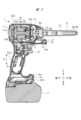
- FIG. 1 is a side view showing the structure of a working machine according to Embodiment 1 of the present invention.
- FIG. 2 is a side sectional view showing the internal structure of the working machine shown in FIG. 1.
- FIG. FIG. 2 is a side view showing the work machine shown in FIG. 1 with the main nozzle removed.
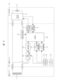
- FIG. 2 is a block circuit diagram showing the configuration of a control system of the working machine shown in FIG. 1.
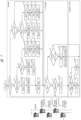
- FIG. FIG. 3 is a diagram for outlining operations in normal mode and on-lock mode and state transitions between these modes.
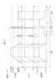
- FIG. 3 is a time chart diagram for comparing and explaining the relationship between the duty ratio and the motor rotation speed with respect to the amount of pull of the trigger. It is a flowchart explaining the control operation of a control part.
- a blower 1 will be described as an example of a working machine.
- the blower 1 is a working machine that takes in air from the back side and discharges it from a nozzle provided on the front side to blow air to a work area, etc., and is also called an air duster.
- a motor 10 a fan 10a that rotates by the driving force of the motor 10 and generates an air flow F1 in an axial direction C1 along the rotational axis of the motor 10, and a motor 10 and a fan 10a that are connected internally.
- a housing part 2 that is housed in a housing part 2 and has an exhaust part 12 on the front (one) side in the axial direction C1, and a main nozzle (nozzle part) 6 that is formed in a cylindrical shape and is detachably attached to the exhaust part 12.
- the housing part 2 includes a motor case (first housing part) 3 that accommodates the motor 10 and the fan 10a therein and has an exhaust part 12, and a motor case (first housing part) 3 that accommodates the motor 10 and the fan 10a therein. It includes an extending handle part 4 and a battery mounting part (second housing part) 5 connected to the handle part 4 so as to be located on the opposite side of the motor case 3 with the handle part 4 in between.
- the motor case 3 and the battery mounting part 5 extend along the axial direction C1 so as to be substantially parallel to each other at both ends of the handle part 4. That is, one end of the handle portion 4 is connected to the motor case 3, and the other end of the handle portion 4 is connected to the battery mounting portion 5.
- the housing part 2 has two housing halves molded from synthetic resin such as nylon or polycarbonate, and is assembled by butting these two housing halves together.
- the direction along the rotational axis of the motor 10 is referred to as the axial direction C1 and is also referred to as the front-rear direction, and furthermore, the direction intersects with the front-rear direction and in which the handle portion 4 extends.
- (Extending direction E1) is called the up-down direction.
- the direction orthogonal to the front-rear direction and the up-down direction is called the left-right direction.
- a motor 10 and a fan 10a are housed within the motor case 3.
- the motor 10 includes a stator 10b that is a coil and a rotor 10c that is a magnet, and is, for example, a brushless motor.
- the fan 10a is a centrifugal fan attached to the rotating shaft of the rotor 10c, and sends air taken in from the intake section 11 at the rear of the motor case 3 toward the main nozzle 6 attached to the front side of the motor case 3.
- the motor 10 including the fan 10a is provided within a cylindrical container.
- the main nozzle 6 is an example of a nozzle.
- the motor 10 takes in air through the mesh part 11a of the intake part 11 by rotating the fan 10a, and sends out the taken air toward the main nozzle 6 along the inner wall 10d of the cylindrical container. At this time, an airflow F1 flowing along the axial direction C1 is generated by the rotation of the fan 10a, and the air sent by the airflow F1 is discharged from the tip of the main nozzle 6.
- a motor board 10e is attached to the motor 10, and this motor board 10e is mounted with an inverter circuit of the motor 10 and a sensor for detecting the rotational position of the rotor 10c.
- This motor board 10e is also housed in the motor case 3. ing.
- the handle portion 4 is provided so as to protrude toward the front (one) side in the axial direction C1 on the motor case 3 side, and is pressed by an operator (not only a human being but also a robot, etc.) (pulling operation by gripping). It has a trigger (operation unit) 9 that can perform The trigger 9 is configured to be able to reciprocate integrally with a trigger switch 9A, which will be described later in FIG. (See detection amount detection section 87 and control section 100).
- a control board 8 on which a microcomputer is mounted is provided inside the handle portion 4. Further, a battery pack 7 that supplies power to the motor 10 is detachably attached to the battery attachment section 5 . Therefore, when the trigger 9 is operated, the fan 10a is rotated by the driving force of the motor 10, and the rotation of the fan 10a generates an airflow F1 in the axial direction C1. In this way, the air taken in from the rear intake section 11 is sent forward as the air flow F1 and is discharged from the tip of the main nozzle 6.
- a protruding portion 15 protruding forward from the motor case 3 is provided directly below the exhaust portion 12 of the motor case 3.
- the protruding part 15 includes an LED 17 that brightly illuminates the area where air is blown, and an upper holding part (first holding part) 13 adjacent to the LED 17. That is, by providing the LED 17 on the protruding portion 15 that protrudes forward from the motor case 3, it is possible to brighten the working area.
- the main nozzle 6 is formed in a cylindrical shape, and has a larger diameter at the other end than at one end.
- the proximal end portion (other end portion) 6b attached to the exhaust portion 12 of the motor case 3 shown in FIG. 2 is provided with an intake port 6d as a nozzle
- the The located tip side portion (one end side portion) 6a is provided with an exhaust port 6e as a nozzle.
- the proximal end portion 6b is thicker than the distal end portion 6a, and has a tapered shape that becomes thinner toward the distal end. Therefore, the relationship is as follows: diameter D2 of the intake port 6d of the proximal end portion 6b>diameter D1 of the exhaust port 6e of the distal end portion 6a.
- a convex portion is formed on the outer periphery of the proximal end portion 6b.
- FIG. 3 is a side view of the work machine shown in FIG. 1 with the main nozzle removed. Note that, as shown in FIG. 3, in the blower 1 of this embodiment, the main nozzle 6 removed from the exhaust section 12 can be fitted (in other words, accommodated) into the motor case 3.
- the main nozzle 6 When attaching the main nozzle 6 to the exhaust part 12 of the motor case 3, fit the convex part of the proximal end portion 6b of the main nozzle 6 into a groove (not shown in detail) provided in the exhaust part 12.
- the main nozzle 6 can be attached to the motor case 3 by rotating the end portion 6b.
- the main nozzle 6 is made of, for example, hard rubber.
- FIG. 4 is a block circuit diagram showing the configuration of the control system of the working machine shown in FIG.
- the blower 1 has a configuration in which a motor output section 30, a battery pack 7, and a board unit 80 are electrically connected.
- the motor output section 30 includes the above-described motor 10 and a motor control section 31 for controlling the electric power supplied to the motor 10 and the operation of the motor 10.
- the motor control unit 31 controls the operation (rotation mode) of the motor 10 based on a control signal output from a control signal output circuit 82, which will be described later. Further, the motor control section 31 detects the rotation speed of the motor 10 and supplies the detection result to the control section 100 through the rotation speed detection circuit 81.
- the battery pack 7 is, for example, a rechargeable secondary battery (such as a lithium ion battery), and as shown in FIG. ) has a structure.
- a rechargeable secondary battery such as a lithium ion battery
- the board unit 80 mainly includes a plurality of circuits mounted on the control board 8 described above. Specifically, the board unit 80 includes connectors 88 and 89 connected to the trigger switch 9A of the trigger (operation unit) 9 described above, and a rotation speed detection circuit connected to the motor control unit 31 of the motor output unit 30. 81 and a control signal output circuit 82.
- the board unit 80 includes a current detection circuit 83, a power switch circuit 84, a power supply circuit 85, a trigger switch operation detection circuit 86, a trigger switch operation amount detection section 87, and the above-mentioned A control unit 100 that controls each circuit (each block) is provided.
- the current detection circuit 83 is connected to the battery pack 7 and the negative electrode side of the motor control section 31 in the motor output section 30, and outputs the detected current value to the control section 100.
- the power switch circuit 84 is connected to the battery pack 7 and outputs whether a main power switch (not shown) is on or off to the power supply circuit 85 .
- the power supply circuit 85 receives a signal indicating that the main power switch is on from the power switch circuit 84, it applies a predetermined voltage to the control unit 100.
- the trigger switch operation detection circuit 86 detects whether or not the trigger switch 9A is operated, and outputs the detection result to the control section 100.
- the trigger switch operation amount detection section 87 detects the operation amount of the trigger switch 9A (which approximately corresponds to the amount of pull of the trigger 9), and outputs the detection result to the control section 100.
- the control unit 100 is, for example, a hardware processor such as a CPU or a microcomputer.
- the control section 100 outputs a control signal to the motor control section 31 through the control signal output circuit 82 according to the detection results of the trigger switch operation detection circuit 86 and the trigger switch operation amount detection section 87.
- the on-lock drive has the following configuration.
- a trigger fixing switch (not shown) (tactile switch described above) is turned on and the trigger 9 is pulled, for example, by the maximum amount, the rotation speed of the motor 10 becomes the amount of operation (pull amount) of the trigger 9.
- the on-lock drive was controlled so that it was fixed regardless of the situation.
- the trigger fixing switch may have either an electrical configuration or a mechanical configuration.
- the conventional configuration as described above uses a fixed trigger switch, which increases the cost. Further, in the conventional configuration described above, it is thought that there is room for improvement regarding the workability of the operator (complexity of operation) when shifting to on-lock drive. Furthermore, the above-mentioned conventional configuration is considered to be a restriction (so to speak, a hindrance) to the development of a multi-stage on-lock drive, in other words, a specification in which the rotation speed of the motor 10 is fixed in multiple stages. .
- the structure is configured to perform on-lock driving.
- the rotation of the motor 10 is switched between a plurality of operation modes, here two modes, a normal mode and an on-lock mode, under the control of the control unit 100 described above.
- a possible configuration Note that it is possible to provide other (third or subsequent) modes as "multiple operation modes," but in order to avoid increasing the number of pages and complicating the explanation, the third and subsequent modes may be provided. An explanation of the modes will be omitted.
- control unit 100 drives the motor 10 while the trigger (operation unit) 9 is located in the on region, and when the trigger 9 is located in the off region. During this period, control is performed to stop driving the motor 10.
- control section 100 controls the rotational speed of the motor 10 according to the amount of movement of the above-mentioned trigger switch 9A, which operates integrally with the trigger (operation section) 9. Since the operation mode of the motor 10 is the same as the conventional one, further detailed explanation will be omitted.
- FIG. 5 is a diagram outlining the operation of the working machine according to the present embodiment in the normal mode and the on-lock mode, and the state transition between these modes.
- the "initial state" of the trigger 9 refers to a state in which the amount of pull of the trigger 9 (operation section) is zero.
- the control unit 100 stops the work. Shift (or maintain) the machine mode to normal mode.
- the motor 10 is driven according to the amount by which the trigger 9 is pulled under the control of the control unit 100.
- the more the trigger 9 is pulled the more power is supplied to the motor 10, causing the motor 10 to rotate at high speed and the air volume.
- the electric power supplied to motor 10 is reduced, the rotational speed of motor 10 is reduced, and the air volume is reduced.
- the on-lock mode is generally a mode in which the amount of power supplied to the motor 10 is fixed.
- the amount of power supplied to the motor 10 is fixed even when the trigger 9 returns to its initial state (zero pull amount) due to the operator releasing the pressure on the trigger 9, etc. This is the mode in which the wind is blown out.
- the on-lock mode includes (1) a "weak on-lock drive state” in which the amount of power supplied to the motor 10 is small, and (2) a “weak on-lock drive state” in which the amount of power supplied to the motor 10 is less than ((1)). It can be roughly divided into two types: ⁇ strong on-lock drive state'', which is often
- the on-lock mode is not limited to the above two modes; for example, it may be configured to include (3) a "medium on-lock drive state" in which the amount of power supplied to the motor 10 is medium; It is also possible to adopt a configuration in which the drive state is subdivided into more stages (such as (4), (5), etc.). On the other hand, since such a subdivided configuration would be complicated to describe in detail, the explanation will be omitted for the sake of simplicity. In the following, the on-lock mode will be explained by focusing on two types: (1) a weak on-lock drive state and (2) a strong on-lock drive state.
- the trigger 9 when the trigger 9 is quickly pulled (pressed) twice and the amount of pull of the trigger 9 exceeds the threshold value both times (as appropriate, "forcible pull” in FIG. ), transition to strong on-lock drive state.
- the strong on-lock drive state in the on-lock mode the amount of power supplied to the motor 10 is greater than in (1) above, so stronger air (wind) is discharged (blown out) from the tip of the main nozzle 6. .
- a configuration may be adopted in which the weak on-lock drive state and the strong on-lock drive state are switched using the total value (in other words, the average value) of the amount of two pulls of the trigger 9 as a threshold value.
- this operation can be expressed figuratively as an operation equivalent to a double click of a mouse, and therefore, hereinafter, this operation may be referred to as a "double click" for convenience.
- FIG. 6 is a time chart for comparing and explaining the relationship between the trigger pull amount, the duty ratio, and the motor rotation speed.
- the graphs shown in three rows in the upper and lower rows in FIG. 6 are timings that compare the values of the amount of pull of the trigger 9 (hereinafter simply referred to as the amount of pull), the DUTY ratio, and the motor rotation speed, respectively from the top. It is a chart, and the horizontal axis of the graph indicates the time axis. Note that the range in which the amount of pull of the trigger 9 is 0 or more and smaller than the contact ON corresponds to the OFF region of the operating section, and the range in which the amount of pulling of the trigger 9 is greater than or equal to the contact ON and less than the full pull amount corresponds to the OFF region of the operating section. corresponds to the ON area of .
- the contact of the trigger switch 9A is turned ON after the amount of pull (see time t2 and "contact ON” in the graph of the amount of pull);
- the DUTY ratio rises to 6% at the right time. With this DUTY ratio of 6%, the motor rotation speed increases to approximately 30,000 (rpm) in this example (see the graph of the rotation speed at time t3).
- the speed adjustment of the motor 10 is started (see the value of "starting speed regulation" in the figure), and the DUTY ratio increases from 6%, and with this increase, the DUTY ratio increases from 6%.
- the rotational speed of the motor 10 further increases (refer to the values of each graph for the period from time t3 to time t4 as appropriate).
- the rotation speed of the motor 10 increases to the maximum speed (approximately 80,000 rotations in this example) (see the graph of the rotation speed at time t4).
- the DUTY ratio remains at 100% until the trigger 9 pull amount corresponds to the maximum speed control and reaches the full pull amount, and the rotation speed of the motor 10 also reaches the maximum speed (approximately 8 10,000 revolutions).
- the rotation speed of the motor 10 remains at the maximum speed (approximately 80,000 rotations) until the amount of pull corresponding to the maximum regulating speed, as described above. (Refer to the values of each graph at time t5 as appropriate).
- the DUTY ratio and the rotation speed of the motor 10 also decrease with the decrease in the amount of pull (as appropriate, from time t5 to time t6). (See the values in each graph for the period ).
- the transition to the weak mode is started, and the motor 10 is driven at a low speed (approximately 30,000 rotations in this example).
- the on-lock state is maintained (see time t11 to time t12).
- the DUTY ratio is maintained at about 6%, as can be seen from the graph shown in the middle part of FIG.
- the rotation speed of the motor 10 at low speed corresponds to the second rotation speed.
- the DUTY ratio is maintained at approximately 100%, as can be seen from the graph shown in the middle part of FIG.
- the rotational speed of the motor 10 at high speed corresponds to the first rotational speed.
- ⁇ Return to normal mode> In the example shown in FIG. 6, as shown at time t16, the trigger 9 is pulled so that the contact of the trigger switch 9A is turned ON during the above-mentioned on-lock state, thereby returning to the normal mode. Return (see period E). In this example, the trigger 9 returns to its initial state at time t17 (DUTY ratio and rotation speed are 6% and 30,000 rpm, respectively), and the motor 10 is stopped at time t18.
- the working machine (air blower 1) of the present embodiment includes the motor 10, the operating section 9 that can be moved from the initial position by the operator's operation, and and a control section 100 that can control the drive of the motor 10 and detect the position of the operation section 9. Then, the control unit 100 performs control to switch to a plurality of operation modes including the normal mode and the on-lock mode. Specifically, in the normal mode, the control unit 100 drives the motor 10 while the operating unit 9 is located in the ON region, and drives the motor 10 while the operating unit 9 is located in the OFF region. to stop. Further, the control unit 100 drives the motor 10 regardless of the position of the operating unit 9 in the on-lock mode.
- control unit 100 when the control unit 100 performs a switching operation that includes positioning the operating unit 9 in the on region multiple times in the normal mode, the control unit 100 switches to the on-lock mode, and in the on-lock mode, the initial state of the operating unit 9 in the switching operation is controlled.
- the operation of the motor 10 is controlled so that the rotation speed of the motor 10 is fixedly set according to the amount of movement from the position.
- the present invention is not limited to the embodiments described above, and can be modified in various ways without departing from the gist thereof.
- the threshold value (first threshold value) TH of the pulling amount is 95% of the maximum speed control of the trigger (operation unit) 9 has been described.
- the value of the threshold value TH is not limited to this, and can be set to any value in the range of 60% to 100% of the maximum speed control.
- time threshold value is 200 ms.
- the time threshold is not limited thereto, and can be set to any value in the range of 60ms to 2000ms.
- Second Groove portion 14...Lower holding part (second holding part holding part), 14a...Protrusion part, 15...Protruding part, 16...Sub nozzle (nozzle part), 17...LED, 18...Accommodation space, 19...Operation space, 30... Motor output section, 31... Motor control base, 80... Board unit, 81... Rotation speed detection circuit, 82... Control signal output circuit, 83... Current detection circuit, 84... Power switch circuit, 85... Power supply circuit, 86...
- Trigger switch detection circuit 87...Trigger switch operation amount detection unit, 88, 89...Connector, 100...Control unit, C1...Axis direction, D1, D2...Aperture, E1...Extending direction, F1...Air flow, G1, G2 ...Diameter, L1...Handle length, L2...Handle + trigger length, L3, L4, L5...Distance
Landscapes
- Engineering & Computer Science (AREA)
- Mechanical Engineering (AREA)
- General Engineering & Computer Science (AREA)
- Control Of Positive-Displacement Air Blowers (AREA)
- Portable Nailing Machines And Staplers (AREA)
- Harvester Elements (AREA)
- Agricultural Machines (AREA)
- Operation Control Of Excavators (AREA)
- Cleaning In General (AREA)
- Portable Power Tools In General (AREA)
Abstract
Description
Claims (8)
- モータと、
作業者の操作によって初期位置から移動可能な操作部と、
前記操作部に対する操作状態に応じて前記モータの駆動を制御し、かつ、前記操作部の位置を検知可能な制御部と、を備え、切替可能であり、
前記制御部は、
前記通常モードにおいて、前記操作部がオン領域に位置している間は前記モータを駆動させ、前記操作部がオフ領域に位置している間は前記モータの駆動を停止させ、
前記オンロックモードにおいて、前記操作部の位置によらず前記モータを駆動させ、
前記制御部は、前記通常モードにおいて前記操作部が前記オン領域に複数回位置することを含む切替動作が行われると、前記動作モードを前記オンロックモードに切り替え、前記オンロックモードにおいては、前記切替動作における前記操作部の前記初期位置からの移動量に応じて前記モータの回転数を設定する、
作業機。 - 前記切替動作は、前記操作部が前記オン領域から前記オフ領域と再度の前記オン領域を経て再度の前記オフ領域に移動する往復動作が行われることである、
請求項1に記載の作業機。 - 前記制御部は、前記オンロックモードにおいて、第1の回転数と、前記第1の回転数よりも回転数の低い第2の回転数と、で前記モータを駆動する制御を行い、
前記制御部は、前記切替動作において前記操作部が前記オン領域に複数回位置することの全てで、前記操作部の前記初期位置からの移動量の最大値が第1閾値を上回ると、前記第1の回転数で前記モータを駆動する、
請求項1に記載の作業機。 - 前記制御部は、前記オンロックモードにおいて、前記操作部が前記オフ領域から前記オン領域へ移動すると、前記通常モードに切り替わるように、前記モータの駆動を制御する、
請求項1に記載の作業機。 - 前記複数回は2回である、
請求項1に記載の作業機。 - 前記第1閾値は、前記操作部の最大調速の60%~100%の範囲に設定されている、
請求項3に記載の作業機。 - 前記制御部は、前記2回の往復動作において、各々の往復動作の時間が60ms~300msの範囲にある場合、前記オンロックモードに移行する処理を行う、
請求項5に記載の作業機。 - 前記モータの駆動力で駆動するファンと、
前記モータ及び前記ファンを収容し、ファンによる空気流の入口となる吸気口及び出口となる排気口を有するハウジングと、
前記排気口に対して着脱可能に装着されるノズルと、を備える、
請求項1に記載の作業機。
Priority Applications (3)
| Application Number | Priority Date | Filing Date | Title |
|---|---|---|---|
| CN202380036594.9A CN119156497A (zh) | 2022-04-28 | 2023-03-31 | 作业机 |
| JP2024517921A JPWO2023210258A1 (ja) | 2022-04-28 | 2023-03-31 | |
| DE212023000233.7U DE212023000233U1 (de) | 2022-04-28 | 2023-03-31 | Arbeitsmaschine |
Applications Claiming Priority (2)
| Application Number | Priority Date | Filing Date | Title |
|---|---|---|---|
| JP2022-074965 | 2022-04-28 | ||
| JP2022074965A JP2025110429A (ja) | 2022-04-28 | 2022-04-28 | 作業機 |
Publications (1)
| Publication Number | Publication Date |
|---|---|
| WO2023210258A1 true WO2023210258A1 (ja) | 2023-11-02 |
Family
ID=88519939
Family Applications (1)
| Application Number | Title | Priority Date | Filing Date |
|---|---|---|---|
| PCT/JP2023/013534 Ceased WO2023210258A1 (ja) | 2022-04-28 | 2023-03-31 | 作業機 |
Country Status (4)
| Country | Link |
|---|---|
| JP (2) | JP2025110429A (ja) |
| CN (1) | CN119156497A (ja) |
| DE (1) | DE212023000233U1 (ja) |
| WO (1) | WO2023210258A1 (ja) |
Cited By (1)
| Publication number | Priority date | Publication date | Assignee | Title |
|---|---|---|---|---|
| WO2026004406A1 (ja) * | 2024-06-27 | 2026-01-02 | オムロン株式会社 | トリガスイッチおよびこれを備えた電動工具、トリガスイッチの制御方法および制御プログラム |
Citations (4)
| Publication number | Priority date | Publication date | Assignee | Title |
|---|---|---|---|---|
| JP2000032099A (ja) * | 1998-07-10 | 2000-01-28 | Nec Saitama Ltd | 背面操作部を有する携帯電話機 |
| JP2000125722A (ja) * | 1998-10-22 | 2000-05-09 | Shimano Inc | 電動リール |
| WO2008013051A1 (en) * | 2006-07-25 | 2008-01-31 | Makita Corporation | Work tool |
| JP2014036939A (ja) * | 2012-08-20 | 2014-02-27 | Hitachi Koki Co Ltd | 電動作業機 |
Family Cites Families (1)
| Publication number | Priority date | Publication date | Assignee | Title |
|---|---|---|---|---|
| JP2020203331A (ja) * | 2019-06-14 | 2020-12-24 | 工機ホールディングス株式会社 | 電動工具 |
-
2022
- 2022-04-28 JP JP2022074965A patent/JP2025110429A/ja active Pending
-
2023
- 2023-03-31 DE DE212023000233.7U patent/DE212023000233U1/de active Active
- 2023-03-31 CN CN202380036594.9A patent/CN119156497A/zh active Pending
- 2023-03-31 WO PCT/JP2023/013534 patent/WO2023210258A1/ja not_active Ceased
- 2023-03-31 JP JP2024517921A patent/JPWO2023210258A1/ja active Pending
Patent Citations (4)
| Publication number | Priority date | Publication date | Assignee | Title |
|---|---|---|---|---|
| JP2000032099A (ja) * | 1998-07-10 | 2000-01-28 | Nec Saitama Ltd | 背面操作部を有する携帯電話機 |
| JP2000125722A (ja) * | 1998-10-22 | 2000-05-09 | Shimano Inc | 電動リール |
| WO2008013051A1 (en) * | 2006-07-25 | 2008-01-31 | Makita Corporation | Work tool |
| JP2014036939A (ja) * | 2012-08-20 | 2014-02-27 | Hitachi Koki Co Ltd | 電動作業機 |
Cited By (1)
| Publication number | Priority date | Publication date | Assignee | Title |
|---|---|---|---|---|
| WO2026004406A1 (ja) * | 2024-06-27 | 2026-01-02 | オムロン株式会社 | トリガスイッチおよびこれを備えた電動工具、トリガスイッチの制御方法および制御プログラム |
Also Published As
| Publication number | Publication date |
|---|---|
| CN119156497A (zh) | 2024-12-17 |
| JPWO2023210258A1 (ja) | 2023-11-02 |
| JP2025110429A (ja) | 2025-07-29 |
| DE212023000233U1 (de) | 2025-02-03 |
Similar Documents
| Publication | Publication Date | Title |
|---|---|---|
| US11407091B2 (en) | Power tool | |
| CN102947057B (zh) | 电动工具和锁定状态发生确定设备 | |
| CN107371563B (zh) | 作业机 | |
| CN109382779B (zh) | 电动作业机 | |
| JP6587110B2 (ja) | 回転打撃工具 | |
| JP5937418B2 (ja) | 流体装置 | |
| JP6041164B2 (ja) | 電動工具 | |
| US9473055B2 (en) | Electric working machine | |
| JP7332039B2 (ja) | 作業機 | |
| JP7281917B2 (ja) | 電動作業機 | |
| WO2023210258A1 (ja) | 作業機 | |
| CN115733393A (zh) | 电动作业机 | |
| CN115703156A (zh) | 驱动钻 | |
| JP2017205834A (ja) | 電動作業機 | |
| JP7367763B2 (ja) | 動力工具 | |
| JP2020001135A (ja) | 電動工具 | |
| US20230086452A1 (en) | Torque output tool and control method for a torque output tool | |
| JP2020203331A (ja) | 電動工具 | |
| JP7832550B2 (ja) | 作業機 | |
| JP7240099B2 (ja) | 電動工具 | |
| JP6759759B2 (ja) | 電動工具 | |
| JP6641607B2 (ja) | 電動工具 | |
| JP2020055105A (ja) | 電動工具 | |
| JP3939488B2 (ja) | オイルユニット衝撃工具 | |
| JP2020116649A (ja) | 電動作業機 |
Legal Events
| Date | Code | Title | Description |
|---|---|---|---|
| 121 | Ep: the epo has been informed by wipo that ep was designated in this application |
Ref document number: 23796005 Country of ref document: EP Kind code of ref document: A1 |
|
| WWE | Wipo information: entry into national phase |
Ref document number: 2024517921 Country of ref document: JP |
|
| WWE | Wipo information: entry into national phase |
Ref document number: 202380036594.9 Country of ref document: CN |
|
| WWE | Wipo information: entry into national phase |
Ref document number: 212023000233 Country of ref document: DE |
|
| WWG | Wipo information: grant in national office |
Ref document number: 212023000233 Country of ref document: DE |
|
| 122 | Ep: pct application non-entry in european phase |
Ref document number: 23796005 Country of ref document: EP Kind code of ref document: A1 |