WO2023209477A1 - リチウムイオン電池、及び電子機器 - Google Patents
リチウムイオン電池、及び電子機器 Download PDFInfo
- Publication number
- WO2023209477A1 WO2023209477A1 PCT/IB2023/053761 IB2023053761W WO2023209477A1 WO 2023209477 A1 WO2023209477 A1 WO 2023209477A1 IB 2023053761 W IB2023053761 W IB 2023053761W WO 2023209477 A1 WO2023209477 A1 WO 2023209477A1
- Authority
- WO
- WIPO (PCT)
- Prior art keywords
- positive electrode
- active material
- electrode active
- lithium
- ion battery
- Prior art date
- Legal status (The legal status is an assumption and is not a legal conclusion. Google has not performed a legal analysis and makes no representation as to the accuracy of the status listed.)
- Ceased
Links
Images



































Classifications
-
- H—ELECTRICITY
- H01—ELECTRIC ELEMENTS
- H01M—PROCESSES OR MEANS, e.g. BATTERIES, FOR THE DIRECT CONVERSION OF CHEMICAL ENERGY INTO ELECTRICAL ENERGY
- H01M10/00—Secondary cells; Manufacture thereof
- H01M10/05—Accumulators with non-aqueous electrolyte
- H01M10/052—Li-accumulators
-
- H—ELECTRICITY
- H01—ELECTRIC ELEMENTS
- H01M—PROCESSES OR MEANS, e.g. BATTERIES, FOR THE DIRECT CONVERSION OF CHEMICAL ENERGY INTO ELECTRICAL ENERGY
- H01M4/00—Electrodes
- H01M4/02—Electrodes composed of, or comprising, active material
- H01M4/36—Selection of substances as active materials, active masses, active liquids
- H01M4/48—Selection of substances as active materials, active masses, active liquids of inorganic oxides or hydroxides
- H01M4/52—Selection of substances as active materials, active masses, active liquids of inorganic oxides or hydroxides of nickel, cobalt or iron
- H01M4/525—Selection of substances as active materials, active masses, active liquids of inorganic oxides or hydroxides of nickel, cobalt or iron of mixed oxides or hydroxides containing iron, cobalt or nickel for inserting or intercalating light metals, e.g. LiNiO2, LiCoO2 or LiCoOxFy
-
- H—ELECTRICITY
- H01—ELECTRIC ELEMENTS
- H01M—PROCESSES OR MEANS, e.g. BATTERIES, FOR THE DIRECT CONVERSION OF CHEMICAL ENERGY INTO ELECTRICAL ENERGY
- H01M50/00—Constructional details or processes of manufacture of the non-active parts of electrochemical cells other than fuel cells, e.g. hybrid cells
- H01M50/10—Primary casings; Jackets or wrappings
- H01M50/102—Primary casings; Jackets or wrappings characterised by their shape or physical structure
- H01M50/105—Pouches or flexible bags
-
- Y—GENERAL TAGGING OF NEW TECHNOLOGICAL DEVELOPMENTS; GENERAL TAGGING OF CROSS-SECTIONAL TECHNOLOGIES SPANNING OVER SEVERAL SECTIONS OF THE IPC; TECHNICAL SUBJECTS COVERED BY FORMER USPC CROSS-REFERENCE ART COLLECTIONS [XRACs] AND DIGESTS
- Y02—TECHNOLOGIES OR APPLICATIONS FOR MITIGATION OR ADAPTATION AGAINST CLIMATE CHANGE
- Y02E—REDUCTION OF GREENHOUSE GAS [GHG] EMISSIONS, RELATED TO ENERGY GENERATION, TRANSMISSION OR DISTRIBUTION
- Y02E60/00—Enabling technologies; Technologies with a potential or indirect contribution to GHG emissions mitigation
- Y02E60/10—Energy storage using batteries
Definitions
- One embodiment of the present invention relates to a lithium ion battery and an electronic device. Further, the present invention is not limited to the above fields, but relates to semiconductor devices, display devices, light emitting devices, power storage devices, lighting devices, electronic devices, vehicles, and manufacturing methods thereof.
- the lithium ion battery of the present invention can be applied to the above-described semiconductor device, display device, light emitting device, power storage device, lighting device, electronic device, and vehicle as a necessary power source.
- the above-mentioned electronic devices include information terminal devices equipped with lithium ion batteries.
- the above-mentioned power storage device includes a stationary power storage device and the like.
- a lithium ion battery (sometimes referred to as a lithium ion secondary battery) refers to a battery using lithium ions as carrier ions, but the carrier ions of the present invention are not limited to lithium ions.
- an alkali metal ion or an alkaline earth metal ion can be used as a carrier ion in the present invention, and specifically, a sodium ion, a magnesium ion, or the like can be used.
- the present invention can be understood by reading lithium ions as sodium ions, magnesium ions, etc.
- a battery that is not limited to carrier ions may also be referred to as a secondary battery.
- Patent Documents 1 to 3 improvements in positive electrode active materials included in positive electrodes of lithium ion batteries are actively being carried out. Furthermore, evaluations have been made to determine the average crushing strength of particles containing crystals of lithium metal composite oxide (for example, Patent Document 4).
- Non-Patent Document 1 Research on the crystal structure of positive electrode active materials has also been conducted (Non-Patent Document 1 and Non-Patent Document 2).
- X-ray diffraction is one of the techniques used to analyze the crystal structure of positive electrode active materials.
- XRD data can be analyzed by using ICSD (Inorganic Crystal Structure Database) introduced in Non-Patent Document 3.
- ICSD Inorganic Crystal Structure Database
- RIETAN-FP Non-Patent Document 7 can be used for the Rietveld method analysis.
- ImageJ Non-Patent Documents 4 to 6
- image processing software for example, ImageJ (Non-Patent Documents 4 to 6) is known.
- ImageJ Non-Patent Documents 4 to 6
- the software it is possible to analyze, for example, the shape of a positive electrode active material.
- JP2019-179758A WO2020/026078 pamphlet JP2020-140954A JP2021-114408A
- an object of one embodiment of the present invention is to provide a positive electrode active material or a composite oxide that can be used in a lithium ion battery and suppresses a decrease in discharge capacity during charge/discharge cycles.
- Another object of the present invention is to provide a positive electrode active material or a composite oxide whose crystal structure does not easily collapse even after repeated charging and discharging.
- one of the objects is to provide a positive electrode active material or a composite oxide with a large discharge capacity.
- one of the challenges is to provide a lithium ion battery with high safety or reliability.
- one embodiment of the present invention is a lithium ion battery having a positive electrode, wherein the positive electrode has a positive electrode active material, the positive electrode active material has lithium cobalt oxide containing magnesium, and the positive electrode active material has lithium cobalt oxide containing magnesium.
- the average crushing strength of lithium oxide is 700 MPa or more, and the positive electrode active material has an O3 type crystal structure in the discharged state, and when the positive electrode is analyzed by powder X-ray diffraction in the charged state, it has a space group R-3m. It has a crystal structure in which cobalt coordinates are (0,0,0.5) and oxygen coordinates are (0,0,x) (0.20 ⁇ x ⁇ 0.25).
- Another embodiment of the present invention is a lithium ion battery having a positive electrode, wherein the positive electrode has a positive electrode active material, the positive electrode active material has lithium cobalt oxide containing magnesium, and the average crushing rate of the lithium cobalt oxide is The strength is 700 MPa or more, and the positive electrode active material has an O3 type crystal structure in a discharged state, and a diffraction peak obtained at a wavelength corresponding to the k ⁇ 1 line when the positive electrode is analyzed with a Cu radiation source in a charged state.
- Another embodiment of the present invention is a lithium ion battery having a positive electrode, wherein the positive electrode has a positive electrode active material, the positive electrode active material has lithium cobalt oxide containing magnesium, and the average crushing rate of the lithium cobalt oxide is The strength is 700 MPa or more, and the positive electrode active material has an O3 type crystal structure at a charging depth of 0.06 or lower, and when the positive electrode is analyzed by powder X-ray diffraction at a charging depth of 0.8 or higher, it has a space group R. -3m, the coordinates of cobalt are (0,0,0.5), and the coordinates of oxygen are (0,0,x) (0.20 ⁇ x ⁇ 0.25).
- Another embodiment of the present invention is a lithium ion battery having a positive electrode, wherein the positive electrode has a positive electrode active material, the positive electrode active material has lithium cobalt oxide containing magnesium, and the average crushing rate of the lithium cobalt oxide is The strength is 700 MPa or more, and the positive electrode active material has an O3 type crystal structure at a charging depth of 0.06 or less, and when the positive electrode is analyzed with a Cu radiation source at a charging depth of 0.8 or more, it becomes a k ⁇ 1 line.
- Another embodiment of the present invention is a lithium ion battery having a positive electrode, wherein the positive electrode has a positive electrode active material, the positive electrode active material has lithium cobalt oxide containing magnesium, and the average crushing rate of the lithium cobalt oxide is The strength is 700 MPa or more, the magnesium concentration in the surface layer of the positive electrode active material is higher than the magnesium concentration inside the positive electrode active material, and the positive electrode active material has an O3 type crystal structure at a charging depth of 0.06 or less.
- the positive electrode is analyzed by powder X-ray diffraction at a charging depth of 0.8 or more, the space group is R-3m, the cobalt coordinates are (0,0,0.5), and the oxygen coordinates are (0,0,0.5). ,0,x) (0.20 ⁇ x ⁇ 0.25).
- the depth of charge is 0 when all lithium ions are inserted based on the theoretical capacity, and 1 when all lithium ions are released.
- the depth of charge of 0.8 or more is a state where the battery is charged to 4.6 V or more in a battery using lithium metal for the positive electrode and the counter electrode.
- the depth of charge of 0.8 or more is a state in which a battery using lithium metal for the positive electrode and the counter electrode is charged until the battery capacity reaches 219.2 mAh/g or more.
- Another embodiment of the present invention is a lithium ion battery having a positive electrode, wherein the positive electrode has a positive electrode active material, the positive electrode active material has lithium cobalt oxide containing magnesium, and the average crushing rate of the lithium cobalt oxide is The strength was 700 MPa or more, the magnesium concentration in the surface layer of the positive electrode active material was higher than the magnesium concentration inside the positive electrode active material, and the battery was charged at 4.6 V in a battery using lithium metal for the positive electrode and counter electrode.
- the positive electrode active material is in the space group R-3m, the coordinates of cobalt are (0, 0, 0.5), and the coordinates of oxygen are It has a crystal structure represented by (0,0,x) (0.20 ⁇ x ⁇ 0.25).
- Another embodiment of the present invention is a lithium ion battery having a positive electrode, wherein the positive electrode has a positive electrode active material, the positive electrode active material has lithium cobalt oxide containing magnesium, and the average crushing rate of the lithium cobalt oxide is The strength was 700 MPa or more, the magnesium concentration in the surface layer of the positive electrode active material was higher than the magnesium concentration inside the positive electrode active material, and the battery was charged at 4.6 V in a battery using lithium metal for the positive electrode and counter electrode.
- FIGS. 1A and 1B are conceptual diagrams of positive electrode active materials.
- 2A1 and 2A2 are cross-sectional views of the positive electrode active material
- FIGS. 2B1 to 2C2 are part of the cross-sectional views of the positive electrode active material.
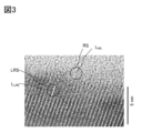
- FIG. 3 is an example of a TEM image in which the crystal orientations are approximately the same.
- FIG. 4A is an example of a STEM image in which the crystal orientations are approximately the same.
- FIG. 4B is an FFT pattern of the region of rock salt type crystal RS.
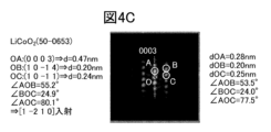
- FIG. 4C is an FFT pattern of a region of layered rock salt type crystal LRS.
- FIG. 5 is a diagram illustrating the crystal structure of the positive electrode active material.
- FIG. 5 is a diagram illustrating the crystal structure of the positive electrode active material.
- FIG. 6 is a diagram illustrating the crystal structure of a conventional positive electrode active material.
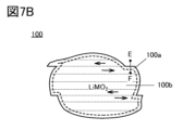
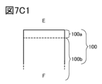
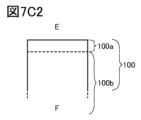
- 7A and 7B are cross-sectional views of the positive electrode active material, and FIGS. 7C1 and 7C2 are part of the cross-sectional views of the positive electrode active material.
- FIG. 8 is a diagram showing an XRD pattern calculated from the crystal structure.
- FIG. 9 is a diagram showing an XRD pattern calculated from the crystal structure.
- FIG. 10 is a cross-sectional view of the positive electrode active material.
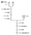
- FIGS. 11A to 11C are diagrams illustrating a method for manufacturing a positive electrode active material.
- FIG. 12 is a diagram illustrating a method for producing a positive electrode active material.
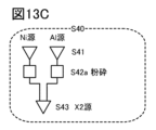
- 13A to 13C are diagrams illustrating a method for producing a positive electrode active material.
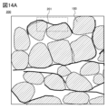
- 14A and 14B are cross-sectional views of an active material layer when a graphene compound is used as a conductive material.
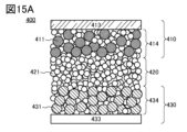
- 15A and 15B are diagrams illustrating an example of a lithium ion battery.
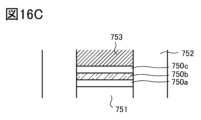
- 16A to 16C are diagrams illustrating an example of a lithium ion battery.
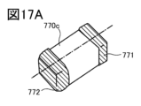
- FIGS. 17A and 17B are diagrams illustrating an example of a lithium ion battery.
- FIGS. 18A to 18C are diagrams illustrating a coin-type lithium ion battery.
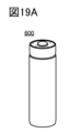
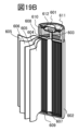
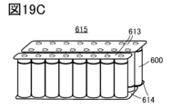
- 19A to 19D are diagrams illustrating a cylindrical lithium ion battery.
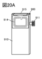
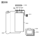
- 20A and 20B are diagrams illustrating an example of a lithium ion battery.
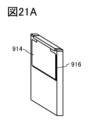
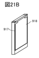
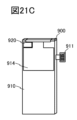
- FIGS. 21A to 21D are diagrams illustrating examples of lithium ion batteries.
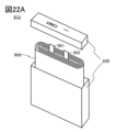
- FIGS. 22A and 22B are diagrams illustrating an example of a lithium ion battery.
- FIG. 23 is a diagram illustrating an example of a lithium ion battery.
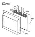
- FIGS. 24A to 24C are diagrams illustrating a laminate type lithium ion battery.
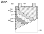
- 25A and 25B are diagrams illustrating a laminate type lithium ion battery.
- FIG. 26 is a diagram showing the appearance of a lithium ion battery.
- FIG. 27 is a diagram showing the appearance of a lithium ion battery.
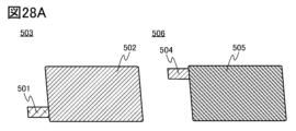
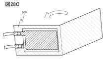
- FIGS. 28A to 28C are diagrams illustrating a method for manufacturing a lithium ion battery.
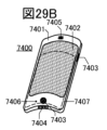
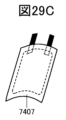
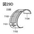
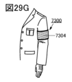
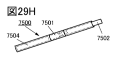
- FIGS. 29A to 29H are diagrams illustrating an example of an electronic device.
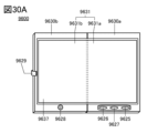
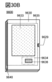
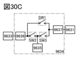
- 30A to 30C are diagrams illustrating an example of an electronic device.
- 31 is a diagram illustrating an example of an electronic device.
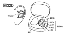
- 32A to 32D are diagrams illustrating an example of an electronic device.
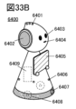
- 33A to 33C are diagrams illustrating an example of an electronic device.
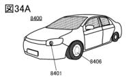
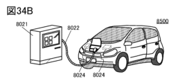
- 34A to 34C are diagrams illustrating an example of a vehicle.
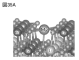
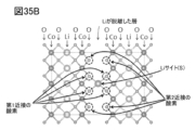
- 35A and 35B are diagrams illustrating calculation models.
- FIGS. 36A and 36B are graphs showing calculation results.
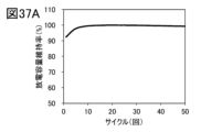
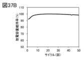
- 37A to 37C are graphs showing cycle test results.
- space groups are expressed using Shortnotation in the international notation (or Hermann-Mauguin symbol).
- crystal planes and crystal directions are expressed using Miller indices. Individual planes indicating crystal planes are written using parentheses. Space groups, crystal planes, and crystal directions are expressed in terms of crystallography by adding a superscript bar to the number, but in this specification etc., due to formatting constraints, instead of adding a bar above the number, they are written in front of the number. It is sometimes expressed by adding a - (minus sign) to it.
- particles are not limited to only spherical shapes (circular cross-sectional shapes), but also particles whose cross-sectional shapes are elliptical, rectangular, trapezoidal, pyramidal, square with rounded corners, and asymmetrical. Examples include shape, and further, individual particles may be amorphous.
- the positive electrode active material refers to a compound containing a transition metal and oxygen that can insert and extract lithium ions. It is assumed that carbonic acid, hydroxyl groups, etc. adsorbed after the production of the positive electrode active material are not included. It also does not include electrolytes, organic solvents, binders, conductive materials, or compounds derived from these that adhere to the positive electrode active material.
- the theoretical capacity of a positive electrode active material refers to the amount of electricity when all the lithium ions that can be intercalated and desorbed from the positive electrode active material are desorbed.
- the theoretical capacity of LiCoO 2 is 274 mAh/g per active material weight
- the theoretical capacity of LiNiO 2 is 274 mAh/g per active material weight
- the theoretical capacity of LiMn 2 O 4 is 148 mAh/g per active material weight.
- charge depth refers to how much capacity is charged based on the theoretical capacity of the positive electrode active material, in other words, how many lithium ions have been desorbed from the positive electrode active material, This value indicates Based on the theoretical capacity, when all the lithium ions are inserted, in other words, LiCoO 2 , the charge depth is 0, and when all the lithium ions are desorbed, in other words, when it is CoO 2 , the charge depth is 1. .
- the depth of charge can be determined assuming that the lithium site has a lithium ion.
- the depth of charge can be determined based on the theoretical capacity of LiCoO 2 . Based on the theoretical capacity of 274 mAh/g, when the charging depth is 0, it means that lithium ions have not been desorbed from the positive electrode, and when the charging depth is 0.5, it corresponds to 137 mAh/g per active material weight. When the depth of charge is 0.8, lithium ions equivalent to 219.2 mAh/g per weight of active material are released from the positive electrode active material.
- lithium cobalt oxide LiCoO 2
- the voltage is 4.6 V (vs. Li/Li + ) or more for a lithium ion battery containing lithium cobalt oxide.
- the state in which the lithium ion battery is charged to a depth of 0.06 or less is a state in which the lithium ion battery is discharged until the voltage becomes 3V (vs. Li/Li + ) or less.
- the amount of lithium ions remaining that can be intercalated and desorbed in the positive electrode active material is expressed by x in the composition formula, for example, x in Li x CoO 2 or x in Li x MO 2 . It can also be shown.
- M means a transition metal that undergoes oxidation-reduction as lithium ions are inserted and removed.
- Li x CoO 2 in this specification can be read as Li x MO 2 as appropriate.
- x (theoretical capacity ⁇ charge capacity)/theoretical capacity.
- x in Li x CoO 2 is small, it means, for example, 0.1 ⁇ x ⁇ 0.24.
- lithium cobalt oxide approximately satisfies the stoichiometric ratio
- the termination of the discharge here refers to a state where the voltage is 2.5 V (vs. Li/Li + ) or less at a current of 100 mA/g per weight of the positive electrode active material, for example.
- the discharge voltage rapidly drops by the time the discharge voltage reaches 2.5V, so it is assumed that the discharge is completed under the above conditions.
- the charging capacity and/or discharging capacity used to calculate x in Li x CoO 2 is preferably measured under conditions where there is no or little influence of short circuits and/or decomposition of electrolyte. For example, data from a lithium-ion battery that has undergone a sudden change in capacity that appears to be a short circuit should not be used to calculate x.
- the space group of the crystal structure is identified by XRD, electron beam diffraction, neutron beam diffraction, or the like. Therefore, in this specification and the like, belonging to a certain space group, belonging to a certain space group, or being a certain space group can be rephrased as identifying with a certain space group.
- an anion has a structure in which three layers are shifted from each other and stacked like ABCABC, it will be referred to as a cubic close-packed structure. Therefore, the anion does not have to be strictly in a cubic lattice.
- the analysis results do not necessarily have to match the theory.
- FFT fast Fourier transform
- TEM Transmission Electron Microscope
- the surface layer portion of a positive electrode active material refers to a region within 50 nm, a region within 10 nm, or a region within 5 nm vertically or substantially perpendicularly from the surface toward the inside from the surface.
- Surface layer portion is synonymous with near surface, near surface region, or shell.
- vertical or substantially vertical specifically refers to a range of 80° or more and 100° or less from the surface.
- a region deeper than the surface layer of the positive electrode active material is called the inside. Internal is synonymous with bulk or core.
- the depth from the surface of the positive electrode active material refers to the distance from the surface in a vertical or approximately vertical direction.
- homogeneity refers to a phenomenon in which a certain element (for example, A) is distributed with similar characteristics in a specific region in a solid composed of a plurality of elements (for example, A, B, and C). Note that it is sufficient that the concentrations of the elements in the specific regions are substantially the same. For example, it is sufficient if the difference in element concentration between specific regions is within 10%.
- Specific areas include, for example, the surface layer, the surface, protrusions, recesses, and the inside.
- cracks are not limited to those generated during the manufacturing process of the positive electrode active material, but include those generated due to subsequent pressurization, charging and discharging, and the like.
- the (001) plane, the (003) plane, etc. are sometimes collectively referred to as the (00l) plane.
- the (00l) plane may be referred to as a C-plane, a basal plane, or the like.
- lithium cobalt oxide lithium has a two-dimensional diffusion path. In other words, it can be said that the diffusion path of lithium exists along the surface.
- a surface other than the surface where the lithium diffusion path is exposed that is, the surface where lithium is intercalated and deintercalated (specifically, the (001) surface) may be referred to as an edge surface.
- a positive electrode active material having an additive element may be expressed as a composite oxide, a positive electrode material, a positive electrode material, a positive electrode material for a lithium ion battery, or the like.
- the positive electrode active material of one embodiment of the present invention preferably contains a compound.
- the positive electrode active material of one embodiment of the present invention preferably has a composition.
- the positive electrode active material of one embodiment of the present invention preferably has a composite.
- the materials included in the lithium ion battery will be described in terms of their state before deterioration.
- the lithium ion battery has a discharge capacity of 97% or more of the rated capacity, it can be said to be in a state before deterioration.
- the rated capacity is based on JIS C 8711:2019.
- the state of the material of a lithium ion battery before deterioration is referred to as the initial product or initial state
- the state after deterioration discharge capacity of less than 97% of the rated capacity of the lithium ion battery
- the state in which the product is used is referred to as a used product or in-use state, or a used product or used state.
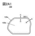
- FIG. 2A1 is a cross-sectional view of a positive electrode active material 100 that can be used in a lithium ion battery according to one embodiment of the present invention.
- the surface of the positive electrode active material 100 is preferably smooth. In order to satisfy the average crushing strength described below, it is preferable that the surface is smooth.
- the positive electrode active material 100 may have grain boundaries. Further, the positive electrode active material 100 may have cracks. Further, the positive electrode active material 100 may have a convex portion. Even if it has grain boundaries, cracks, and/or convex portions, the positive electrode active material 100 can satisfy the average crushing strength.
- FIG. 1 is a cross-sectional view of a positive electrode active material 100 that can be used in a lithium ion battery according to one embodiment of the present invention.
- the surface of the positive electrode active material 100 is preferably smooth. In order to satisfy the average crushing strength described below, it is preferable that the surface is smooth.
- the positive electrode active material 100 may have grain boundaries. Further, the positive electrode active material 100
- FIGS. 2A2 shows a cross-sectional view of the positive electrode active material 100 having grain boundaries 101, cracks 102, and convex portions 103 indicated by dotted lines.
- the positive electrode active material 100 has a surface layer portion 100a and an interior portion 100b.
- the boundary between the surface layer 100a and the interior 100b is indicated by a broken line.
- FIGS. 2B1 and 2B2 are enlarged views of the area around AB in FIG. 2A1.
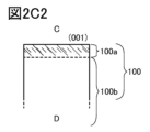
- FIGS. 2C1 and 2C2 are enlarged views of the area around CD in FIG. 2A1.
- the boundary between the surface layer portion 100a and the interior portion 100b is indicated by a broken line.
- the positive electrode active material 100 preferably has an average crushing strength of 700 MPa or more, preferably 650 MPa or more.
- the positive electrode active material 100 preferably has an average crushing strength of 700 MPa or more, preferably 650 MPa or more, at least in a discharged state.
- the average crushing strength of the positive electrode active material 100 described in this specification etc. is preferably filled with a positive electrode active material obtained by disassembling a lithium ion battery; Just satisfy it. In other words, since the positive electrode active material obtained by disassembling a lithium ion battery may be affected by side reactions of the electrolyte, etc., the above-mentioned average crushing strength may not be accurately determined.
- the lithium ion battery has a discharge capacity of 97% or more of the rated capacity, there is no effect of the above side reactions, or even if it occurs, it is slight, so the lithium ion battery has a discharge capacity of 97% or more of the rated capacity. It is desirable that the positive electrode active material obtained by disassembling the material satisfies the above average crushing strength.
- the positive electrode active material 100 is a compound containing a transition metal M (for example, one or more selected from Co, Ni, Mn, and Fe) capable of intercalating and deintercalating lithium ions, and oxygen. It can also be called a composite oxide.
- a transition metal M for example, one or more selected from Co, Ni, Mn, and Fe
- the surface of the positive electrode active material 100 refers to the surface of the composite oxide including the surface layer portion 100a, the interior portion 100b, the convex portions 103, and the like. Therefore, it is assumed that the positive electrode active material 100 does not contain carbonate, hydroxyl groups, etc. that are chemically adsorbed after fabrication. It is also assumed that the electrolyte, binder, conductive material, or compounds derived from these adhered to the positive electrode active material 100 are not included. When the positive electrode active material 100 has a region where the transition metal M and oxygen are not present, the surface of the positive electrode active material 100 has an interface between the region where the transition metal M and oxygen are present and the region where the transition metal M and oxygen are not present. do. In addition, surfaces caused by slips, cracks, and/or cracks can also be referred to as the surface of the positive electrode active material.
- the surface of the positive electrode active material in energy dispersive X-ray spectroscopy (EDX) line analysis, etc. is defined as The point where the transition metal or oxygen is closest to 50% of the average value of the internal detected amount is defined as the point. Note that if the measured values closest to 50% of the average values of the detected amounts inside the transition metal and oxygen are different, the one located further outside can be adopted.
- the intersection point is the tangent drawn to the intensity profile of the EDX-ray analysis of the transition metal or oxygen and the axis in the depth direction. Note that even if the values of the intersection points are different, the intersection point located on the outer side can be adopted.
- the surface of a positive electrode active material in a STEM (Scanning Transmission Electron Microscope) image, etc. is the boundary between a region where an image derived from the crystal structure of the positive electrode active material is observed and a region where it is not observed, and is This is the outermost region in which an atomic column originating from the nucleus of a metal element with a higher atomic number is confirmed. Alternatively, it is the intersection of the tangent drawn to the brightness profile from the surface toward the inside of the STEM image and the axis in the depth direction.
- the surface in a STEM image or the like may be determined in conjunction with the results of analysis with higher spatial resolution, such as electron energy loss spectroscopy (EELS).
- EELS electron energy loss spectroscopy
- the crystal grain boundaries 101 are, for example, areas where the positive electrode active materials 100 are stuck together, areas where the crystal orientation changes inside the positive electrode active materials 100, in other words, the repetition of bright lines and dark lines in a STEM image etc. becomes discontinuous.
- crystal defects refer to defects that can be observed in cross-sectional TEM (transmission electron microscope) images, cross-sectional STEM images, etc., that is, structures in which other elements enter between lattices, cavities, etc.
- the grain boundary 101 can be said to be one of the planar defects.
- the vicinity of the grain boundary 101 refers to a region within 10 nm from the grain boundary 101.
- the crack 102 may also be referred to as a region where the crystal plane is shifted or a region where the crystal plane is broken, and it often occurs along the (00l) plane.
- the positive electrode active material 100 includes lithium, a transition metal M, oxygen, and an additive element A.
- the positive electrode active material 100 may include a composite oxide containing lithium and a transition metal M (compositional formula is LiMO 2 ) to which an additive element A is added.
- the positive electrode active material to which the additive element A is added may also be referred to as a composite oxide.
- the positive electrode active material of a lithium ion battery needs to contain a transition metal capable of redox in order to maintain charge neutrality even when lithium ions are intercalated and deintercalated.
- cobalt is preferably mainly used as the transition metal M responsible for the redox reaction.
- at least one or more selected from nickel and manganese may be used.
- the transition metal M included in the positive electrode active material 100 if cobalt accounts for 75 atomic % or more, preferably 90 atomic % or more, and more preferably 95 atomic % or more, it is relatively easy to synthesize, easy to handle, and has excellent cycle characteristics. It is preferable because it has many advantages.
- nickel such as lithium nickelate (LiNiO 2 ) is the transition metal M.
- cobalt is 75 atomic % or more, preferably 90 atomic % or more, and more preferably 95 atomic % or more of the transition metal M of the positive electrode active material 100
- nickel such as lithium nickelate (LiNiO 2 ) is the transition metal M.
- stability is better when x is small. This is thought to be because cobalt is less affected by distortion due to the Jahn-Teller effect than nickel.
- the strength of the Jahn-Teller effect in transition metal compounds differs depending on the number of electrons in the d orbital of the transition metal.
- the raw material becomes cheaper compared to when the amount of cobalt is large. This is preferable because it may increase the discharge capacity per weight.
- Additional elements A included in the positive electrode active material 100 include magnesium, fluorine, nickel, aluminum, titanium, zirconium, vanadium, iron, manganese, chromium, niobium, arsenic, zinc, silicon, sulfur, phosphorus, boron, bromine, and beryllium. It is preferable to use one or more selected from the following.
- the positive electrode active material 100 includes lithium cobalt oxide to which magnesium and fluorine are added, lithium cobalt oxide to which magnesium, fluorine and titanium are added, lithium cobalt oxide to which magnesium, fluorine and aluminum are added, magnesium, fluorine and nickel. It can have added lithium cobalt oxide, lithium cobalt oxide added with magnesium, fluorine, nickel and aluminum, and the like.
- additive elements A further stabilize the crystal structure of the positive electrode active material 100, as described below. Note that in this specification and the like, the additive element A has the same meaning as a mixture or a part of raw materials.
- the additive element A does not necessarily include magnesium, fluorine, nickel, aluminum, titanium, zirconium, vanadium, iron, manganese, chromium, niobium, arsenic, zinc, silicon, sulfur, phosphorus, boron, bromine, or beryllium. good.
- the positive electrode active material 100 is substantially free of manganese, the above-mentioned advantages such as being relatively easy to synthesize, easy to handle, and having excellent cycle characteristics are further enhanced. It is preferable that the weight of manganese contained in the positive electrode active material 100 is, for example, 600 ppm or less, more preferably 100 ppm or less. The weight of manganese can be analyzed using, for example, GD-MS (glow discharge mass spectrometry).
- GD-MS low discharge mass spectrometry
- Lithium cobalt oxide (LCO) which is the positive electrode active material 100 of one embodiment of the present invention, preferably has a layered rock salt crystal structure belonging to space group R-3m in a discharge state. Furthermore, in the layered rock salt type crystal structure, lithium ions occupy octahedral sites, and three CoO 2 layers exist in the unit cell. Therefore, the layered rock salt type crystal structure is sometimes called an O3 type crystal structure. Note that the CoO 2 layer refers to a structure in which an octahedral structure in which six oxygen atoms are coordinated with cobalt is continuous in a plane in a shared edge state.
- a “discharge state” refers to a case where x in Li x CoO 2 is 0.94 or more, a case where the depth of charge is 0.06 or less, or a case where the SOC (State of Charge) is 100%. It's okay.
- FIG. 5 an O3 type crystal structure is shown at a position where the charging depth overlaps with 0.
- the “discharge state” refers to a state where the voltage is 3 V (vs. Li/Li + ) or less, typically 2.5 V (vs. Li/Li + ) when lithium metal is used as the counter electrode.
- a positive electrode active material with a layered rock salt crystal structure such as lithium cobalt oxide, has a high discharge capacity, has a two-dimensional lithium ion diffusion path, and is suitable for lithium ion insertion/extraction reactions. Excellent as a positive electrode active material for ion batteries. Therefore, it is particularly preferable that the interior 100b, which occupies most of the volume of the positive electrode active material 100, has a layered rock salt crystal structure.
- the surface layer 100a of the positive electrode active material 100 may have a function of reinforcing the layered structure of the two CoO layers in the interior 100b so that it does not break even if lithium ions are removed from the positive electrode active material 100 due to charging.
- the surface layer portion 100a functions as a barrier film for the positive electrode active material 100.
- the surface layer portion 100a which is the outer peripheral portion of the positive electrode active material 100, reinforces the positive electrode active material 100.
- Reinforcement here refers to suppressing structural changes in the surface layer 100a and interior 100b of the positive electrode active material 100, including desorption of oxygen, and/or oxidative decomposition of the electrolyte on the surface of the positive electrode active material 100. It means to suppress something.
- the surface layer portion 100a has a crystal structure different from that of the interior portion 100b. Further, it is preferable that the surface layer portion 100a has a composition and crystal structure that are more stable at room temperature (25° C.) than the interior portion 100b. For example, it is preferable that at least a portion of the surface layer portion 100a of the positive electrode active material 100 according to one embodiment of the present invention has a rock salt crystal structure. Alternatively, the surface layer portion 100a preferably has both a layered rock salt type crystal structure and a rock salt type crystal structure. Alternatively, the surface layer portion 100a preferably has characteristics of both a layered rock salt type and a rock salt type crystal structure.
- the surface layer portion 100a is a region where lithium ions are first desorbed during charging, and is a region where the lithium concentration tends to be lower than that in the interior portion 100b. Further, it can be said that the atoms on the surface of the positive electrode active material 100 that the surface layer portion 100a has have some bonds broken. Therefore, the surface layer portion 100a tends to become unstable, and can be said to be a region where the crystal structure tends to deteriorate.
- the surface layer 100a can be made sufficiently stable, even when x in Li x CoO 2 is small, for example, even if x is 0.24 or less, the layered structure consisting of two CoO layers in the interior 100b can be made difficult to break. Furthermore, displacement of the two layers of CoO in the interior 100b can be suppressed.
- x in Li x CoO 2 is small, for example, a state of 0.24 or less may be read as a state where the depth of charge is 0.8 or more.
- the surface layer portion 100a preferably contains an additive element A, and more preferably contains a plurality of elements selected as the additive element A. Further, it is preferable that the concentration of one or more of the additive elements A is higher in the surface layer portion 100a than in the interior portion 100b. Further, it is preferable that one or more selected from the additive elements A included in the positive electrode active material 100 have a concentration gradient. Further, it is more preferable that the positive electrode active material 100 has a different distribution for each additive element A. For example, it is more preferable that the position of the peak indicating the concentration (concentration peak), that is, the depth from the surface, differs for each additive element A.
- additive elements A such as magnesium, fluorine, nickel, titanium, silicon, phosphorus, boron, calcium, etc.
- concentration gradient As follows. An element having such a concentration gradient will be referred to as an additive element X.
- another additive element A such as aluminum or manganese
- the concentration peak of another additive element A may be present in the surface layer portion 100a or may be deeper than the surface layer portion 100a. For example, it is preferable to have a concentration peak in a region at a depth of 5 nm or more and 30 nm or less from the surface.
- An element having such a concentration gradient will be referred to as an additive element Y.
- magnesium which is one of the additive elements X, is divalent, and magnesium ions may be more stable in lithium sites than in cobalt sites in a layered rock salt type crystal structure, and can easily enter the lithium sites.
- Magnesium may have a distribution similar to that of the additive element Y.
- the presence of magnesium at an appropriate concentration in the lithium sites of the surface layer 100a makes it easier to maintain the layered rock salt crystal structure. This is presumed to be because the magnesium present at the lithium site functions as a pillar that supports the two CoO layers. Furthermore, the presence of magnesium can suppress desorption of oxygen around magnesium when x in Li x CoO 2 is, for example, 0.24 or less. Furthermore, the presence of magnesium can be expected to increase the density of the positive electrode active material 100. Furthermore, when the magnesium concentration in the surface layer portion 100a is high, it can be expected that corrosion resistance against hydrogen fluoride produced by decomposition of the electrolytic solution will be improved.
- magnesium is at an appropriate concentration, it will not adversely affect insertion and desorption of lithium ions during charging and discharging, and the above advantages can be enjoyed. However, if magnesium is in excess, insertion and desorption of lithium ions may be adversely affected. Furthermore, the effect on stabilizing the crystal structure may be reduced. This is thought to be because magnesium enters the cobalt site in addition to the lithium site. In addition, unnecessary magnesium compounds (oxides, fluorides, etc.) that do not substitute for either lithium sites or cobalt sites may segregate on the surface of the positive electrode active material and become a resistance component of the lithium ion battery. Furthermore, as the magnesium concentration of the positive electrode active material increases, the discharge capacity of the positive electrode active material may decrease. This is thought to be because too many magnesium ions enter the lithium site, reducing the amount of lithium that contributes to charging and discharging.
- the entire positive electrode active material 100 has an appropriate amount of magnesium.
- the atomic ratio of magnesium to cobalt (Mg/Co) in the positive electrode active material 100 of one embodiment of the present invention is preferably 0.25% or more and 5% or less, more preferably 0.5% or more and 2% or less. , about 1% is more preferable.
- the amount of magnesium contained in the entire positive electrode active material 100 herein may be a value obtained by elemental analysis of the entire positive electrode active material 100 using, for example, GD-MS, ICP-MS, etc. It may be based on the value of the composition of raw materials in the process of producing the substance 100.
- Nickel which is one of the additive elements X, can exist in both the cobalt site and the lithium site. When present in cobalt sites, the oxidation-reduction potential becomes lower than that of cobalt, which leads to an increase in discharge capacity, which is preferable. Nickel may have a distribution similar to that of the additive element Y.
- the entire positive electrode active material 100 has an appropriate amount of nickel.
- the number of nickel atoms in the positive electrode active material 100 is preferably higher than 0% and 7.5% or less of the number of cobalt atoms, preferably 0.05% or more and 4% or less, and 0.1% or more and 2% or less. It is preferably 0.2% or more and 1% or less. Alternatively, it is preferably higher than 0% and 4% or less. Alternatively, it is preferably higher than 0% and 2% or less. Or preferably 0.05% or more and 7.5% or less. Or preferably 0.05% or more and 2% or less. Or preferably 0.1% or more and 7.5% or less. Or preferably 0.1% or more and 4% or less.
- the amount of nickel shown here may be, for example, a value obtained by elemental analysis of the entire positive electrode active material using GD-MS, ICP-MS, etc., or a value obtained in the process of producing the positive electrode active material. It may also be based on the value of the blend of raw materials.
- aluminum which is one of the additive elements Y, can exist in cobalt sites in a layered rock salt crystal structure.
- Aluminum is a typical trivalent element and its valence does not change, so lithium around aluminum is difficult to move during charging and discharging. Therefore, aluminum and the lithium surrounding it function as pillars and can suppress changes in the crystal structure. Additionally, aluminum has the effect of suppressing the elution of surrounding cobalt and improving continuous charging resistance. Furthermore, since the Al--O bond is stronger than the Co--O bond, desorption of oxygen around aluminum can be suppressed. These effects improve thermal stability. Therefore, when aluminum is included as the additive element Y, safety can be improved when used in a lithium ion battery. Moreover, the positive electrode active material 100 can be made such that the crystal structure does not easily collapse even after repeated charging and discharging. Aluminum may have a distribution similar to that of the additive element X.
- the entire positive electrode active material 100 has an appropriate amount of aluminum.
- the number of aluminum atoms contained in the entire positive electrode active material 100 is preferably 0.05% or more and 4% or less, preferably 0.1% or more and 2% or less, and 0.3% or more and 1.5% or less of the number of cobalt atoms. % or less is more preferable. Or preferably 0.05% or more and 2% or less. Or preferably 0.1% or more and 4% or less.
- the amount that the entire positive electrode active material 100 has here may be, for example, a value obtained by elemental analysis of the entire positive electrode active material 100 using GD-MS, ICP-MS, etc. It may also be based on the value of the blending of raw materials in the process of producing the active material 100.
- fluorine which is one of the additive elements X
- fluorine is a monovalent anion
- fluorine in the surface layer portion 100a when a part of oxygen is replaced with fluorine in the surface layer portion 100a, the lithium ion desorption energy becomes small. This is because the valence of cobalt ions changes due to lithium ion desorption from trivalent to quadrivalent in the case of no fluorine, and from bivalent to trivalent in the case of fluorine, and the redox potential is different. . Therefore, if part of the oxygen in the surface layer 100a of the positive electrode active material 100 is replaced with fluorine, it can be said that desorption and insertion of lithium ions near fluorine are likely to occur smoothly.
- Fluorine may have a distribution similar to that of the additive element Y.
- the melting point of fluorides such as lithium fluoride
- a fluxing agent also called a fluxing agent
- Titanium which is one of the additive elements X, has superhydrophilicity. Therefore, by using the positive electrode active material 100 having titanium oxide in the surface layer portion 100a, the wettability with respect to a highly polar solvent may be improved. When used as a lithium ion battery, the interface between the positive electrode active material 100 and the highly polar electrolytic solution becomes good, and there is a possibility that an increase in internal resistance can be suppressed. Titanium may have a distribution similar to that of the additive element Y.
- phosphorus which is one of the additive elements X
- Phosphorus may have a distribution similar to that of the additive element Y.
- the positive electrode active material 100 contains phosphorus
- hydrogen fluoride generated by decomposition of the electrolyte and phosphorus may react, and the hydrogen fluoride concentration in the electrolyte may be reduced, which is preferable.
- hydrogen fluoride may be generated due to hydrolysis.
- the reaction between phosphorus and hydrogen fluoride reduces the concentration of hydrogen fluoride in the electrolytic solution, which may suppress corrosion of the current collector and/or peeling of the coating.
- hydrogen fluoride may be generated due to the reaction between polyvinylidene fluoride (PVDF) used as a binder and an alkali.
- PVDF polyvinylidene fluoride
- the reaction between phosphorus and hydrogen fluoride may suppress a decrease in adhesiveness due to gelation and/or insolubilization of PVDF.
- the positive electrode active material 100 contains phosphorus together with magnesium because stability in a state where x in Li x CoO 2 is small is extremely high.
- the number of phosphorus atoms is preferably 1% or more and 20% or less of the number of cobalt atoms, more preferably 2% or more and 10% or less, and even more preferably 3% or more and 8% or less. Or preferably 1% or more and 10% or less. Or preferably 1% or more and 8% or less. Or preferably 2% or more and 20% or less. Or preferably 2% or more and 8% or less. Or preferably 3% or more and 20% or less. Or preferably 3% or more and 10% or less.
- the number of magnesium atoms is preferably 0.1% or more and 10% or less of the number of cobalt atoms, more preferably 0.5% or more and 5% or less, and more preferably 0.7% or more and 4% or less. Or preferably 0.1% or more and 5% or less. Or preferably 0.1% or more and 4% or less. Or preferably 0.5% or more and 10% or less. Or preferably 0.5% or more and 4% or less. Or preferably 0.7% or more and 10% or less. Or preferably 0.7% or more and 5% or less.
- concentrations of phosphorus and magnesium shown here may be values obtained by elemental analysis of the entire positive electrode active material 100 using GC-MS, ICP-MS, etc., or values of the positive electrode active material 100. It may also be based on the value of the composition of raw materials during the manufacturing process.
- the positive electrode active material 100 has a crack 102
- phosphorus more specifically, a compound containing phosphorus and oxygen, exists in the recessed part (also called a buried part) of the positive electrode active material with the crack 102 as the surface. The progress of the crack 102 can be suppressed.
- the surface layer portion 100a contains both magnesium and nickel, there is a possibility that divalent magnesium can exist more stably near divalent nickel. Therefore, elution of magnesium can be suppressed even when x in Li x CoO 2 is small. Therefore, it can contribute to stabilization of the surface layer portion 100a.
- the positive electrode active material 100 also contain additive elements A having different distributions, such as additive element X and additive element Y, because the crystal structure in a wider region can be stabilized.
- additive elements A having different distributions, such as additive element X and additive element Y
- the positive electrode active material 100 contains both magnesium and nickel, which are part of the additive element X, and aluminum, which is one of the additive elements Y
- the positive electrode active material 100 has a higher It is possible to stabilize the crystal structure in a wide range.
- the positive electrode active material 100 has both the additive element X and the additive element Y, the additive element do not have.
- it is preferable for aluminum to be widely distributed in a region deeper than the surface layer. For example, by widely distributing aluminum in a region with a depth of 5 nm or more and 50 nm or less from the surface, the crystal structure of the interior 100b can be further stabilized.
- each additive element A When a plurality of additive elements A are included as described above, the effects of each additive element A are synergized and can contribute to further stabilization of the surface layer portion 100a.
- magnesium, nickel, and aluminum are highly effective in providing a stable composition and crystal structure, and are therefore preferable.
- the surface layer portion 100a is occupied only by the compound of the additive element A and oxygen, it is not preferable because it becomes difficult to insert and extract lithium ions.
- the surface layer portion 100a is occupied only by MgO, a structure in which MgO and NiO(II) are dissolved in solid solution, and/or a structure in which MgO and CoO(II) are dissolved in solid solution. Therefore, the surface layer portion 100a must contain at least cobalt, also contain lithium in the discharge state, and have a path for inserting and extracting lithium ions.
- the entrance through which lithium ions are inserted into and removed from the surface of the positive electrode active material 100 is sometimes called a window or a window frame.
- the surface layer portion 100a has a higher concentration of cobalt than magnesium.
- the ratio Mg/Co of the number of atoms of magnesium, Mg, and the number of atoms of cobalt, Co is preferably 0.62 or less.
- the surface layer portion 100a has a higher concentration of cobalt than nickel.
- the surface layer portion 100a has a higher concentration of cobalt than aluminum.
- the surface layer portion 100a has a higher concentration of cobalt than fluorine.
- the surface layer portion 100a has a higher concentration of magnesium than nickel.
- the number of nickel atoms is preferably 1/6 or less of the number of magnesium atoms.
- some of the additive elements A particularly magnesium, nickel, and aluminum, preferably have a higher concentration in the surface layer 100a than in the interior 100b, but it is also preferable that they exist randomly and dilutely in the interior 100b.
- magnesium and aluminum are present at appropriate concentrations in the lithium sites in the interior 100b, there is an effect that the layered rock salt type crystal structure can be easily maintained as described above.
- nickel is present in the interior 100b at an appropriate concentration, displacement of the layered structure consisting of two CoO layers can be suppressed in the same manner as described above.
- divalent magnesium may exist more stably near divalent nickel, so a synergistic effect of suppressing the elution of magnesium can be expected.
- the crystal structure changes continuously from the interior 100b toward the surface due to the concentration gradient of the additive element A as described above.
- the boundary between the surface layer 100a and the interior 100b may not be clear.
- the crystal orientations of the surface layer portion 100a and the interior portion 100b match or approximately match.
- the crystal structure changes continuously from the layered rock-salt type interior 100b toward the surface and surface layer portion 100a that has the characteristics of the rock-salt type or both the rock-salt type and the layered rock-salt type.
- the orientations of the surface layer portion 100a, which has the characteristics of a rock salt type or both of a rock salt type and a layered rock salt type, and the orientation of the layered rock salt type interior 100b are the same or approximately the same.
- the layered rock salt type crystal structure belonging to space group R-3m which is possessed by a positive electrode active material containing a transition metal M such as cobalt, has a rock salt type ion arrangement in which cations and anions are arranged alternately.
- the transition metal M and lithium are regularly arranged to form a two-dimensional plane, it refers to a crystal structure that allows two-dimensional diffusion of lithium ions.
- the layered rock salt crystal structure there may be defects such as cation or anion deficiencies. Strictly speaking, the layered rock salt crystal structure may have a structure in which the lattice of the rock salt crystal is distorted.
- the rock salt type crystal structure has a cubic crystal structure including a space group Fm-3m, and refers to a structure in which cations and anions are arranged alternately. Note that in the rock salt type crystal structure, there may be a cation or anion deficiency.
- the positive electrode active material 100 has both the characteristics of a layered rock salt type crystal structure and a rock salt type crystal structure.
- the rock salt type has no distinction in the cation sites, but the layered rock salt type crystal structure has two types of cation sites, one mostly occupied by lithium and the other occupied by the transition metal M.
- the layered structure in which two-dimensional planes of cations and two-dimensional planes of anions are arranged alternately is the same for both the rock salt type and the layered rock salt type.
- the central spot transparent spot
- the bright spot closest to the central spot is the rock salt type.
- it is a (111) plane
- a layered rock salt type it is a (003) plane.
- the bright spot on the (003) plane of LiCoO 2 is approximately half the distance of the bright spot on the (111) plane of MgO. be observed. Therefore, when the analysis region has two phases, for example, rock salt type MgO and layered rock salt type LiCoO2 , the electron diffraction pattern has a plane orientation in which bright spots with strong brightness and bright spots with weak brightness are arranged alternately. do. Bright spots common to the halite type and layered halite type have strong brightness, and bright spots that occur only in the layered halite type have weak brightness.
- Layered rock salt crystals and anions of rock salt crystals have a cubic close-packed structure (face-centered cubic lattice structure).
- the anions are also presumed to have a cubic close-packed structure. Therefore, when a layered rock salt crystal and a rock salt crystal come into contact, there is a crystal plane in which the cubic close-packed structure composed of anions is oriented in the same direction.
- Anions in the ⁇ 111 ⁇ plane of the cubic crystal structure have a triangular lattice.
- the layered rock salt type has a space group R-3m and has a rhombohedral structure, but to facilitate understanding of the structure, it is generally expressed as a complex hexagonal lattice, and the (0001) plane of the layered rock salt type has a hexagonal lattice.
- the triangular lattice of the cubic ⁇ 111 ⁇ plane has an atomic arrangement similar to the hexagonal lattice of the (0001) plane of the layered rock salt type. When both lattices are consistent, it can be said that the orientations of the cubic close-packed structures are aligned.
- the space group of layered rock salt crystals and O3' type crystals is R-3m, which is different from the space group Fm-3m of rock salt crystals (the space group of general rock salt crystals), so the above conditions are
- the Miller index of the crystal planes to be satisfied is different between a layered rock salt type crystal and an O3' type crystal and a rock salt type crystal.
- layered rock salt type crystals, O3' type crystals, and rock salt type crystals when the directions of the cubic close-packed structures constituted by anions are aligned, the orientations of the crystals coincide or approximately coincide, or topotaxy ) or epitaxy.
- Topotaxis refers to having three-dimensional structural similarity such that the crystal orientations match or approximately match, or having the same crystallographic orientation.
- epitaxy refers to the structural similarity of two-dimensional interfaces.
- the fact that the orientations of the crystals in the two regions match or approximately match means that the orientations of the crystals in the two regions match or approximately match in a TEM image, a STEM image, a HAADF-STEM (High-angle Annular Dark Field Scanning Transmission Electron Microscope) image, and an ABF-STEM image.
- a TEM image a STEM image
- HAADF-STEM High-angle Annular Dark Field Scanning Transmission Electron Microscope
- ABF-STEM image An ABF-STEM image.
- eHCI-TEM enhanced Hollow-Cone Il lumination-TEM, improved hollow cone illumination transmission electron microscope
- FIG. 3 shows an example of a TEM image in which the orientations of the layered rock salt crystal LRS and the rock salt crystal RS match or approximately match.
- a TEM image, a STEM image, a HAADF-STEM image, an ABF-STEM image, etc. provide images that reflect the crystal structure.
- contrast derived from crystal planes can be obtained. Due to diffraction and interference of the electron beam, for example, when an electron beam is incident perpendicularly to the c-axis of a layered rock-salt complex hexagonal lattice, the contrast originating from the (0003) plane is divided into a bright band (bright strip) and a dark band (dark strip). ) is obtained by repeating. Therefore, if repeating bright lines and dark lines are observed in the TEM image, and the angle between the bright lines (for example, LRS and LLRS shown in FIG.
- contrast is obtained in proportion to the atomic number, and elements with larger atomic numbers are observed brighter.
- cobalt atomic number 27
- the electron beam is strongly scattered at the position of the cobalt atom, making the arrangement of the cobalt atoms clear. It can be observed as a line or as an array of bright points.
- lithium cobalt oxide which has a layered rock salt crystal structure
- the arrangement of cobalt atoms perpendicular to the c-axis is observed as a bright line or an arrangement of strong bright points, and lithium atoms and oxygen atoms are observed perpendicularly to the c-axis.
- the arrangement is observed as a dark line or region of low brightness.
- fluorine (atomic number 9) and magnesium (atomic number 12) are used as additive elements of lithium cobalt oxide.
- FIG. 4A shows an example of a STEM image in which the orientations of the layered rock salt crystal LRS and the rock salt crystal RS match or approximately match.
- FIG. 4B shows the FFT of the region of the rock salt crystal RS
- FIG. 4C shows the FFT of the region of the layered rock salt crystal LRS.
- the left side of FIGS. 4B and 4C shows the composition, the JCPDS (Joint Committee on Powder Diffraction Standard) card number, and the d value and angle calculated from this. Actual values are shown on the right.
- the spot marked with O is the 0th order of diffraction, and the center position of the spot is marked with X.
- the spots labeled A in FIG. 4B originate from the 11-1 reflection of the cubic crystal.
- the spots labeled A in FIG. 4C are derived from layered rock salt type 0003 reflections. It can be seen from FIGS. 4B and 4C that the orientation of the 11-1 reflection of the cubic crystal and the orientation of the 0003 reflection of the layered rock salt type match or approximately match. That is, it can be seen that the straight line passing through AO in FIG. 4B and the straight line passing through AO in FIG. 4C are approximately parallel.
- Coincidence, roughly coinciding, and roughly parallel as used herein mean that the angle is 0 degrees or more and 5 degrees or less, or 0 degrees or more and 2.5 degrees or less.
- the ⁇ 0003> orientation of the layered rock salt type and the ⁇ 11-1> orientation of the rock salt type can be determined. , may match or approximately match.
- these reciprocal lattice points are spot-like, that is, not continuous with other reciprocal lattice points.
- the fact that the reciprocal lattice points are spot-like and not continuous with other reciprocal lattice points means that the crystallinity is high.
- the direction of the 11-1 reflection of the cubic crystal and the direction of the 0003 reflection of the layered rock salt type match or approximately match, depending on the incident direction of the electron beam
- the direction of the 0003 reflection of the layered rock salt type On a reciprocal lattice space different from the direction of reflection, a layered rock salt-type spot that is not derived from 0003 reflection may be observed.
- the spots labeled B in FIG. 4C are derived from layered rock salt type 1014 reflections.
- ⁇ AOB is 52° or more and 56° or less
- d may be observed at a location of 0.19 nm or more and 0.21 nm or less.
- this index is just an example, and does not necessarily have to match this index.
- equivalent reciprocal lattice points in each may be used.
- a spot that is not derived from the 11-1 reflection of the cubic crystal may be observed on a reciprocal space different from the direction in which the 11-1 reflection of the cubic crystal is observed.
- the spot labeled B in FIG. 4B is derived from 200 reflections of a cubic crystal. This is a diffraction spot at a location that is at an angle of 54° or more and 56° or less (that is, ⁇ AOB is 54° or more and 56° or less) from the direction of the reflection derived from cubic crystal 11-1 (A in Figure 4B). may be observed.
- this index is just an example, and does not necessarily have to match this index.
- equivalent reciprocal lattice points in each may be used.
- layered rock salt type positive electrode active materials such as lithium cobalt oxide, (0003) planes and planes equivalent to this, and (10-14) planes and planes equivalent to this tend to appear as crystal planes.
- SEM scanning electron microscope
- SEM scanning electron microscope
- it is preferable to thin the layered rock salt so that the (0003) plane can be easily observed.
- the positive electrode active material 100 of one embodiment of the present invention has the above-mentioned distribution of additive element A and/or crystal structure in the discharge state, and therefore the crystal structure in the charged state is different from that of the conventional positive electrode active material. different from.
- state of charge may be referred to as a case where x in Li x CoO 2 is small or a case where the depth of charge is large. Note that x is small here, which means 0.1 ⁇ x ⁇ 0.24. Note that here, a large depth of charge means 0.8 or more.
- Chargeged state refers to a state where the voltage is 4.6 V (vs. Li/Li + ) or higher when lithium metal is used as the counter electrode, and in this case, the battery capacity is 219.2 mAh/g per weight of active material. That's all.
- FIGS. 5 to 9 A change in the crystal structure due to a change in x in Li x CoO 2 will be explained using FIGS. 5 to 9 while comparing a conventional cathode active material and the cathode active material 100 of one embodiment of the present invention.
- FIG. 6 shows changes in the crystal structure of conventional positive electrode active materials.
- the conventional positive electrode active material shown in FIG. 6 is lithium cobalt oxide (LiCoO 2 ) that does not particularly contain the additive element A.
- LiCoO 2 lithium cobalt oxide
- changes in the crystal structure of lithium cobalt oxide without additive element A are described in Non-Patent Document 1 and Non-Patent Document 2, etc., but in the discharge state, the O3 type crystal structure is shown in both FIGS. 5 and 6. .
- an O3 type crystal structure is shown at a position where the charging depth overlaps with 0.
- the positive electrode active material has a crystal structure of trigonal space group P-3m1, and the CoO 2 layer is 1 in the unit cell. There are layers. Therefore, this crystal structure is sometimes called O1 type or trigonal O1 type. In addition, the trigonal crystal is sometimes converted into a complex hexagonal lattice and is called the hexagonal O1 type.
- FIG. 6 an O1 type crystal structure belonging to space group P-3m1 is shown at a position where the charging depth overlaps with 1.
- This structure can be said to be a structure in which a CoO 2 structure like trigonal O1 type and a LiCoO 2 structure like R-3m(O3) are alternately stacked. Therefore, this crystal structure is sometimes called an H1-3 type crystal structure.
- the c-axis of the H1-3 type crystal structure is shown as 1/2 of the unit cell.
- the coordinates of cobalt and oxygen in the unit cell are Co(0, 0, 0.42150 ⁇ 0.00016), O1(0, 0, 0.27671 ⁇ 0.00045), O2 (0, 0, 0.11535 ⁇ 0.00045).
- O1 and O2 are each oxygen atoms.
- Which unit cell should be used to represent the crystal structure of the positive electrode active material can be determined, for example, by Rietveld analysis of the XRD pattern. In this case, a unit cell with a small GOF (goodness of fit) value may be used.
- the depth of charge is 0, that is, the discharge state where x in Li x CoO 2 is 1, and the depth of charge is 0.88, that is, x is 0.24 or less.
- the crystal structure changes less in the charged state than in conventional cathode active materials. More specifically, it is possible to reduce the deviation between the two CoO layers between a discharge state where the depth of charge is 0, that is, x is 1, and a charge state where the depth of charge is 0.88, that is, x is 0.24 or less. Further, the change in volume when compared per cobalt atom can be reduced.
- the cathode active material 100 has excellent cycle performance, with its crystal structure not easily collapsing even after repeated charging and discharging such that the depth of charge is 0.88, that is, x is 0.24 or less. characteristics can be realized.
- the positive electrode active material 100 of one embodiment of the present invention has a crystal structure that is more stable than conventional positive electrode active materials in a charged state where the depth of charge is 0.88, that is, x in Li x CoO 2 is 0.24 or less. It can be taken. Therefore, the safety of the lithium ion battery is further improved, which is preferable.
- the crystal structure shown in FIG. 5 is one that the interior 100b of the positive electrode active material 100 has when x in Li x CoO 2 is about 1 and 0.2. Since the interior 100b occupies most of the volume of the positive electrode active material 100 and is a part that greatly contributes to charging and discharging, it can be said that the displacement of the CoO 2 layer and the change in volume are the most problematic part.
- the positive electrode active material 100 has the same R-3m (O3) crystal structure as conventional lithium cobalt oxide.
- the positive electrode active material 100 shown in FIG. 5 has a charge depth of 0.88 at which conventional lithium cobalt oxide has an H1-3 type crystal structure, that is, x is 0.24 or less, for example, about 0.2 or 0. When it is about 12, it has a crystal with a different structure.
- the positive electrode active material 100 of one embodiment of the present invention when the depth of charge is about 0.8, that is, when x 0.2, has a crystal structure belonging to the trigonal space group R-3m. This is because the symmetry of the CoO 2 layer is the same as that of O3. Therefore, this crystal structure will be referred to as an O3' type crystal structure.
- R-3m (O3') is attached to a position where the charging depth overlaps with 0.8 to indicate an O3' type crystal structure.
- the coordinates of cobalt and oxygen in the unit cell are Co(0,0,0.5), O(0,0,x) (within the range of 0.20 ⁇ x ⁇ 0.25). ).
- ions such as cobalt, nickel, and magnesium occupy six oxygen coordination positions. Note that a light element such as lithium may occupy the 4-coordination position of oxygen.
- the difference in volume per same number of cobalt atoms between R-3m(O3) in the discharge state and the O3' type crystal structure is 2.5% or less, more specifically 2.2% or less, typically 1. It is 8%.
- the change in the crystal structure when the depth of charge is deep that is, when x in Li x CoO 2 is small, that is, when many lithium ions are desorbed, This is more suppressed than conventional positive electrode active materials.
- changes in volume are also suppressed when comparing the same number of cobalt atoms. Therefore, the crystal structure of the positive electrode active material 100 does not easily collapse even after repeated charging and discharging such that the depth of charge is 0.88, that is, x is 0.24 or less. Therefore, the decrease in discharge capacity of the positive electrode active material 100 during charge/discharge cycles is suppressed.
- the positive electrode active material 100 has a large discharge capacity per weight and per volume. Therefore, by using the positive electrode active material 100, a lithium ion battery with high discharge capacity per weight and per volume can be manufactured.
- the positive electrode active material 100 may have an O3' type crystal structure when the depth of charge is 0.85 or less and 0.76 or more, that is, when x in Li x CoO 2 is 0.15 or more and 0.24 or less. was confirmed, and it is estimated that even if the charging depth is smaller than 0.76 and 0.73 or more, that is, x is larger than 0.24 and 0.27 or less, it has an O3' type crystal structure.
- the crystal structure is affected not only by the charging depth or x in Li x CoO 2 but also by the number of charging and discharging cycles, charging and discharging current, temperature, electrolyte, etc., it is not necessarily limited to the above numerical range.
- the depth of charge of the positive electrode active material 100 is less than 0.9 and 0.76 or more, and when x in Li x CoO 2 is higher than 0.1 and 0.24 or less, all of the interior 100b of the positive electrode active material 100 is does not have to have an O3' type crystal structure. It may contain other crystal structures, or may be partially amorphous.
- a state in which the charging depth is deep that is, a state in which x in Li x CoO 2 is small
- a state in which the battery is charged at a high charging voltage can be rephrased as a state in which the battery is charged at a high charging voltage.
- a charging voltage of 4.6 V or more can be said to be a high charging voltage with reference to the potential of lithium metal.
- the charging voltage is expressed based on the potential of lithium metal.
- the positive electrode active material 100 of one embodiment of the present invention can maintain a crystal structure with R-3m(O3) symmetry even when charged at a high charging voltage, for example, at a voltage of 4.6 V or higher at 25°C. It can be said that it is preferable. In addition, it can be said that it is preferable because an O3' type crystal structure can be obtained when charged at a higher charging voltage, for example, a voltage of 4.65 V or more and 4.7 V or less at 25° C.
- the positive electrode active material 100 Even in the positive electrode active material 100, H1-3 type crystals may be finally observed when the charging voltage is further increased. Furthermore, as mentioned above, the crystal structure is affected by the number of charge/discharge cycles, charge/discharge current, electrolyte, etc., so when the charging voltage is lower, for example, even if the charging voltage is 4.5 V or more and less than 4.6 V at 25°C, the The positive electrode active material 100 of one embodiment of the invention may have an O3' type crystal structure.
- the voltage of the lithium ion battery is lowered by the difference between the potential of graphite and the potential of lithium metal.
- the potential of graphite is about 0.05V to 0.2V based on the potential of lithium metal. Therefore, in the case of a lithium ion battery that uses graphite as the negative electrode active material, it has a similar crystal structure when the voltage obtained by subtracting the potential of graphite from the above voltage is applied.
- lithium ions are shown to exist at all lithium sites with equal probability, but the present invention is not limited to this. It may exist biasedly at some lithium sites, or it may have a symmetry such as monoclinic O1 (Li 0.5 CoO 2 ) shown in FIG. 6, for example.
- the distribution of lithium can be analyzed, for example, by neutron diffraction.
- the O3' type crystal structure can also be said to be a crystal structure similar to the CdCl 2 type crystal structure, although it has lithium randomly between the layers.
- This crystal structure similar to CdCl type 2 is close to the crystal structure when lithium nickelate is charged to Li 0.06 NiO 2 , but pure lithium cobalt oxide or a layered rock salt type positive electrode active material containing a large amount of cobalt is It is known that CdCl does not normally have a type 2 crystal structure.
- the concentration gradient of the additive element A be the same at a plurality of locations in the surface layer portion 100a of the positive electrode active material 100.
- the reinforcement derived from the additive element A exists homogeneously in the surface layer portion 100a. Even if a portion of the surface layer portion 100a is reinforced, if there is a portion without reinforcement, stress may be concentrated on the portion without reinforcement. When stress is concentrated on a portion of the positive electrode active material 100, defects such as cracks may occur there, leading to cracking of the positive electrode active material and a decrease in discharge capacity.
- the additive element A does not necessarily have to have the same concentration gradient in all the surface layer portions 100a of the positive electrode active material 100.
- An example of the distribution of the additive element X near CD in FIG. 2A1 is shown in FIG. 2C1, and an example of the distribution of the additive element Y near CD in FIG. 2C2 is shown.
- the area near CD has a layered rock salt type crystal structure of R-3m, has a (001) plane, and is a (001) oriented surface layer.
- the (001) oriented surface layer portion there are regions where a plurality of (001) planes coincide or approximately coincide with each other.
- the (001) oriented surface layer portion may have a different distribution of the additive element A, for example, the distribution in the depth direction, from the surface layer portions having other surfaces.
- the distribution of one or more selected from the additive element may have been done.
- the (001) oriented surface layer portion may have a lower concentration of one or more selected from the additive element X and the additive element Y compared to the surface layer portion oriented in a plane other than the (001) plane.
- the surface layer portion oriented in a plane other than the (001) plane has a region in which a plurality of planes other than the (001) plane coincide or approximately coincide with each other.
- the (001) plane where the CoO 2 layer is present on the surface is relatively stable.
- the main diffusion path of lithium ions during charging and discharging is not exposed on the (001) plane.
- lithium ion diffusion paths are exposed on surfaces other than the (001) plane. Therefore, surfaces other than the (001) plane and the surface layer having such planes are important regions for maintaining the diffusion path of lithium ions, and at the same time, they are unstable because they are the regions where lithium ions are first desorbed. Cheap. Therefore, it is extremely important to reinforce the plane other than the (001) plane and the surface layer portion having the plane in order to maintain the crystal structure of the positive electrode active material 100 as a whole.
- the distribution of the additive element A in the surface other than the (001) plane and in the surface layer having the plane is as shown in FIGS. 2B1 and 2B2. This is very important.
- the concentration of the additive element A may be low as described above, or may be absent.
- the additive element A spreads mainly through the diffusion path of lithium ions. Therefore, it is easy to set the distribution of the additive element A in a plane other than the (001) plane and the surface layer portion having the plane in a preferable range.
- the surface of the positive electrode active material 100 is smooth and has few irregularities, the surface of the positive electrode active material 100 does not necessarily have to be smooth.
- the positive electrode active material 100 having a layered rock salt type crystal structure of R-3m tends to slip easily in a plane parallel to the (001) plane, for example, a plane in which lithium is arranged. For example, if there is a (001) plane as shown in Figure 7A, slipping may occur in parallel to the (001) plane as shown by the arrow in Figure 7B through processes such as pressing, which may cause deformation. .
- the additive element A may not be present on the surface newly generated as a result of the slip and its surface layer portion 100a.
- E-F in FIG. 7B is an example of a newly generated surface and its surface layer as a result of slipping.
- FIGS. 7C1 and 7C2 are enlarged views of the area around E-F. In FIGS. 7C1 and 7C2, unlike in FIGS. 2B1 and 2C2, the additive element X and the additive element Y are not distributed.
- cobalt is arranged parallel to the (001) plane. Furthermore, in the HAADF-STEM image, the brightness of cobalt, which has the largest atomic number among LiCoO 2 , is the highest. Therefore, in the HAADF-STEM image, the arrangement of atoms with high brightness can be considered to be the arrangement of cobalt. This repeated arrangement of high brightness is synonymous with crystal fringes or lattice fringes.
- the additive element A that the positive electrode active material 100 of one embodiment of the present invention has is unevenly distributed at least partially in the grain boundaries 101 and the vicinity thereof.
- maldistribution means that the concentration of an element in a certain region is different from that in other regions. It has the same meaning as segregation, precipitation, non-uniformity, deviation, or a mixture of areas with high concentration and areas with low concentration.
- the magnesium concentration in the grain boundaries 101 of the positive electrode active material 100 and in the vicinity thereof is higher than in other regions of the interior 100b.
- the fluorine concentration in the grain boundaries 101 and the vicinity thereof is also higher than in other regions of the interior 100b.
- the nickel concentration in the grain boundaries 101 and the vicinity thereof is also higher than in other regions of the interior 100b.
- the aluminum concentration in the grain boundaries 101 and the vicinity thereof is also higher than in other regions of the interior 100b.
- Grain boundaries 101 are one type of planar defect. Therefore, like the surface, it tends to become unstable and the crystal structure tends to change. Therefore, if the concentration of the additive element A at the grain boundary 101 and its vicinity is high, changes in the crystal structure can be suppressed more effectively. Further, when the magnesium concentration and fluorine concentration at and near the grain boundaries 101 are high, even if cracks occur along the grain boundaries 101 of the positive electrode active material 100 of one embodiment of the present invention, the surface caused by the cracks Magnesium and fluorine concentrations increase in the vicinity. Therefore, the corrosion resistance against hydrogen fluoride can be improved even in the positive electrode active material after cracks have occurred.
- the median diameter (D50) is preferably 1 ⁇ m or more and 100 ⁇ m or less, more preferably 2 ⁇ m or more and 40 ⁇ m or less, and even more preferably 5 ⁇ m or more and 30 ⁇ m or less.
- the thickness is preferably 1 ⁇ m or more and 40 ⁇ m or less.
- the thickness is preferably 1 ⁇ m or more and 30 ⁇ m or less.
- the thickness is preferably 2 ⁇ m or more and 100 ⁇ m or less. Or preferably 2 ⁇ m or more and 30 ⁇ m or less.
- the thickness is preferably 5 ⁇ m or more and 100 ⁇ m or less.
- the thickness is preferably 5 ⁇ m or more and 40 ⁇ m or less.
- Whether a certain positive electrode active material is the positive electrode active material 100 of one embodiment of the present invention having an O3' type crystal structure when x in Li x CoO 2 is small is determined by whether x in Li x CoO 2 is small. This can be determined by analyzing a positive electrode containing a positive electrode active material using XRD, electron beam diffraction, neutron diffraction, electron spin resonance (ESR), nuclear magnetic resonance (NMR), or the like.
- XRD can analyze the symmetry of the transition metal M such as cobalt in the positive electrode active material with high resolution, can compare the crystallinity height and crystal orientation, and can analyze the periodic strain of the lattice and the crystallite size. This method is preferable because sufficient accuracy can be obtained even when the positive electrode obtained by disassembling a lithium ion battery is directly measured.
- powder XRD provides a diffraction peak that reflects the crystal structure of the interior 100b of the positive electrode active material 100, which occupies most of the volume of the positive electrode active material 100.
- the positive electrode active material 100 of one embodiment of the present invention is characterized by a small change in crystal structure between when x in Li x CoO 2 is 1 and when x is 0.24 or less.
- a material in which 50% or more of the crystal structure changes significantly when charged at a high voltage is not preferable because it cannot withstand high voltage charging and discharging.
- the positive electrode active material 100 of one embodiment of the present invention if x is too small, such as 0.1 or less, or under conditions where the charging voltage exceeds 4.9 V, the crystal structure of the H1-3 type or trigonal O1 type will change. This may occur in some cases. Therefore, in order to determine whether the positive electrode active material 100 of one embodiment of the present invention is used, analysis of the crystal structure such as XRD, and information such as charging capacity or charging voltage are required.
- the positive electrode active material in a state where x is small may undergo a change in crystal structure when exposed to the atmosphere.
- the O3' type crystal structure may change to the H1-3 type crystal structure. Therefore, it is preferable that all samples subjected to crystal structure analysis be handled in an inert atmosphere such as an argon atmosphere.
- the crystal structure of the surface layer portion 100a, grain boundaries 101, etc. can be analyzed by electron beam diffraction or the like of a cross section of the positive electrode active material 100.
- Whether a certain positive electrode active material is the positive electrode active material 100 of one embodiment of the present invention can be determined by performing high voltage charging.
- a battery (sometimes referred to as a test battery or coin cell) may be fabricated using the positive electrode active material for the positive electrode and lithium metal for the negative electrode (also referred to as a counter electrode), and then charged at a high voltage.
- the battery may be of CR2032 type, with a diameter of 20 mm and a height of 3.2 mm.
- the positive electrode may be prepared by coating a positive electrode current collector made of aluminum foil with a slurry in which a positive electrode active material, a conductive material, and a binder are mixed.
- Lithium metal can be used for the counter electrode. Note that when a material other than lithium metal is used for the counter electrode, the potential of the lithium ion battery and the potential of the positive electrode are different. Voltages and potentials in this specification and the like are the potentials of the positive electrode unless otherwise mentioned.
- a polypropylene porous film with a thickness of 25 ⁇ m can be used as the separator.
- the positive electrode can and the negative electrode can may be made of stainless steel (SUS).
- the coin cell produced under the above conditions is heated to an arbitrary voltage (for example, 4.5V, 4.55V, 4.6V, 4.65V, 4.7V, 4.75V or 4.8V) with a current value of 10 mA per weight of active material. /g constant current charging. In order to observe the phase change of the positive electrode active material, it is desirable to perform charging at such a small current value.
- the temperature is preferably 25°C.
- XRD can be performed in a sealed container with an argon atmosphere.
- the discharge can be a constant current discharge at 3.0 V and 100 mA/g per weight of active material.
- the conditions for charging and discharging the plurality of times may be different from the above-mentioned charging conditions.
- charging is performed by constant current charging at a current value of 100 mA/g per weight of active material to an arbitrary voltage (for example, 4.6 V, 4.65 V, 4.7 V, 4.75 V or 4.8 V), and then the current value is Constant voltage charging can be performed until the voltage reaches 10 mA/g, and constant current discharge can be performed to 3.0 V at a current value of 100 mA/g per weight of active material.
- constant current discharge can be performed at the above-mentioned 3.0V and current value of 100mA/g, for example.
- ⁇ XRD ⁇ XRD can obtain an XRD pattern within a specified range.
- a diffraction peak is confirmed in the XRD pattern, and the interplanar distance or lattice constant can be determined as a physical quantity based on the 2 ⁇ value of the peak top of the diffraction peak, and therefore information on the crystal structure can be obtained.
- XRD measurement can be performed using the following equipment and conditions.
- XRD device Bruker AXS, D8 ADVANCE
- X-ray source CuK ⁇ ray output: 40kV, 40mA Divergence angle: Div.
- K ⁇ rays corresponding to K ⁇ radiation can be confirmed in the XRD pattern, but the K ⁇ rays may appear to be split into two peaks; the one with higher intensity is called K ⁇ 1 ray, and the smaller one is called K ⁇ 2 ray. call.
- a diffraction peak using a high-intensity K ⁇ 1 line can also be called a diffraction peak obtained at a wavelength corresponding to the CuK ⁇ 1 line.
- the measurement sample When the measurement sample is powder, it is called powder X-ray diffraction (XRD) measurement.
- XRD powder X-ray diffraction
- the sample can be set in the XRD apparatus by placing it in a glass holder or sprinkling it on a greased silicone non-reflective plate.
- the measurement sample is a positive electrode active material
- a powder containing the positive electrode active material may be prepared.
- the positive electrode When the measurement sample is a positive electrode, the positive electrode can be attached to the substrate with double-sided tape and set so that the positive electrode active material layer faces the measurement surface of the device.
- FIG. 8 shows XRD patterns of LiCoO 2 (O3) and the O3′ type crystal structure for comparison.
- FIG. 9 shows XRD patterns of LiCoO 2 (O3), H1-3 type crystal structure, and CoO 2 (O1) for comparison.
- LiCoO 2 is Li x CoO 2 when x is 1, and CoO 2 is when x is 0.
- the XRD patterns of LiCoO 2 (O3) and CoO 2 (O1) are one of the modules of Materials Studio (BIOVIA) from the crystal structure information obtained from ICSD (Inorganic Crystal Structure Database) (see Non-Patent Document 3). It was created using Reflex Powder Diffraction. The pattern of the crystal structure of type H1-3 was created using Reflex Powder Diffraction from the crystal structure information described in Non-Patent Document 2.
- the XRD pattern of the O3' type crystal structure can be created by performing powder XRD measurement on the positive electrode active material in a charged state using the above apparatus and under the above conditions, and using software for powder XRD. can.
- the above software includes DIFFRAC.
- EVA manufactured by Bruker
- the K ⁇ 2 line can be cut from the output value.
- parameters that are physically superior can be determined using software such as TOPAS (manufactured by Bruker). For example, lattice constants can be obtained using TOPAS.
- the positive electrode active material 100 has an O3' type crystal structure when x in Li x CoO 2 is small, all of the positive electrode active material 100 does not have to have an O3' type crystal structure. It may contain other crystal structures, or may be partially amorphous. However, when Rietveld analysis is performed on the XRD pattern, the O3' type crystal structure is preferably 50% or more, more preferably 60% or more, and even more preferably 66% or more. If the O3' type crystal structure is 50% or more, more preferably 60% or more, even more preferably 66% or more, the positive electrode active material can have sufficiently excellent cycle characteristics.
- the O3' type crystal structure is preferably 35% or more, more preferably 40% or more, and 43% or more when subjected to Rietveld analysis. It is more preferable that it is above.
- the analysis program RIETAN-FP (see Non-Patent Document 7) can be used.
- each diffraction peak after charging be sharp, that is, have a narrow half-width.
- the half width varies depending on the XRD measurement conditions or the 2 ⁇ value even for peaks generated from the same crystal phase.
- the half-width is preferably 0.2° or less, more preferably 0.15° or less, and 0.12° or less. More preferred. Note that not all peaks necessarily satisfy this requirement. If some peaks satisfy this requirement, it can be said that the crystallinity of the crystal phase is high. Such high crystallinity contributes to sufficient stabilization of the crystal structure after charging.
- X-ray photoelectron spectroscopy uses monochromatic aluminum K ⁇ rays as the X-ray source to detect a region from the surface to a depth of approximately 2 nm to 8 nm (typically 5 nm or less). Since analysis is possible, it is possible to quantitatively analyze the concentration of each element in a region that is approximately half the depth of the surface layer portion 100a. Additionally, narrow scan analysis allows the bonding state of elements to be analyzed. Note that the quantitative accuracy of XPS is about ⁇ 1 atomic % in most cases, and the lower limit of detection is about 1 atomic %, although it depends on the element.
- the concentration of one or more selected from the additive elements A is higher in the surface layer portion 100a than in the interior portion 100b.
- concentration of one or more selected additive elements A in the surface layer portion 100a is preferably higher than the average of the entire positive electrode active material 100. Therefore, for example, the concentration of one or more additive elements A selected from the surface layer 100a measured by It can be said that it is preferable that the concentration of the added element A be higher than the average concentration of the additive element A in the entire substance 100.
- the magnesium concentration in at least a portion of the surface layer portion 100a measured by XPS or the like is higher than the magnesium concentration in the entire positive electrode active material 100.
- the nickel concentration in at least a portion of the surface layer portion 100a is higher than the nickel concentration in the entire positive electrode active material 100.
- the aluminum concentration in at least a portion of the surface layer portion 100a is higher than the aluminum concentration in the entire positive electrode active material 100.
- the fluorine concentration in at least a portion of the surface layer portion 100a is higher than the fluorine concentration in the entire positive electrode active material 100.
- the surface and surface layer portion 100a of the positive electrode active material 100 do not contain carbonate, hydroxyl groups, etc. that are chemically adsorbed after the positive electrode active material 100 is produced. It is also assumed that the electrolytic solution, binder, conductive material, or compounds derived from these adhered to the surface of the positive electrode active material 100 are not included. Therefore, when quantifying the elements contained in the positive electrode active material, correction may be made to exclude carbon, hydrogen, excess oxygen, excess fluorine, etc. that can be detected by surface analysis such as XPS. For example, in XPS, it is possible to separate the types of bonds by analysis, and correction may be performed to exclude binder-derived C-F bonds.
- samples such as the positive electrode active material and the positive electrode active material layer are washed, etc., before being subjected to various analyses. You may do so. At this time, lithium ions may dissolve into the solvent used for cleaning, but even in that case, the additive element A is difficult to dissolve, so the atomic ratio of the additive element A is not affected.
- the concentration of the additive element A may be compared in terms of its ratio to cobalt.
- the ratio to cobalt it is possible to reduce the influence of carbonic acid, etc. chemically adsorbed after the positive electrode active material is produced, and to make a comparison, which is preferable.
- the ratio Mg/Co of the number of atoms of magnesium and cobalt as determined by XPS analysis is preferably 0.4 or more and 1.5 or less.
- Mg/Co as determined by ICP-MS analysis is preferably 0.001 or more and 0.06 or less.
- the concentration of lithium and cobalt is higher than that of each additive element A in the surface layer portion 100a in order to sufficiently secure a path for insertion and desorption of lithium ions.
- the concentration of lithium and cobalt in the surface layer 100a is preferably higher than the concentration of one or more of the additive elements A selected from the additive elements A contained in the surface layer 100a, as measured by XPS or the like. be able to.
- the concentration of cobalt in at least a portion of the surface layer portion 100a measured by XPS or the like is higher than the concentration of magnesium in at least a portion of the surface layer portion 100a measured by XPS or the like.
- the concentration of lithium is higher than the concentration of magnesium.
- the concentration of cobalt is higher than the concentration of nickel.
- the concentration of lithium is higher than the concentration of nickel.
- the concentration of cobalt is higher than that of aluminum.
- the concentration of lithium is higher than the concentration of aluminum.
- the concentration of cobalt is higher than that of fluorine.
- the concentration of lithium is higher than that of fluorine.
- the additive element Y including aluminum is widely distributed in a deep region, for example, in a region with a depth of 5 nm or more and 50 nm or less from the surface. Therefore, although the additive element Y including aluminum is detected in the analysis of the entire positive electrode active material 100 using ICP-MS, GD-MS, etc., this may be below the detection limit in XPS etc.
- the number of magnesium atoms is preferably 0.4 times or more and 1.2 times or less, and 0.65 times or more and 1 times or less, relative to the number of cobalt atoms. More preferably, it is .0 times or less.
- the number of nickel atoms is preferably 0.15 times or less, more preferably 0.03 times or more and 0.13 times or less relative to the number of cobalt atoms.
- the number of aluminum atoms is preferably 0.12 times or less, more preferably 0.09 times or less, relative to the number of cobalt atoms.
- the number of fluorine atoms is preferably 0.3 times or more and 0.9 times or less, more preferably 0.1 times or more and 1.1 times or less, relative to the number of cobalt atoms.
- the take-out angle may be, for example, 45°.
- the take-out angle may be, for example, 45°.
- it can be measured using the following equipment and conditions.
- the peak indicating the bond energy between fluorine and another element is preferably 682 eV or more and less than 685 eV, and more preferably about 684.3 eV. This value is different from both 685 eV, which is the binding energy of lithium fluoride, and 686 eV, which is the binding energy of magnesium fluoride. That is, when the positive electrode active material 100 of one embodiment of the present invention contains fluorine, the bond is preferably other than lithium fluoride and magnesium fluoride.
- the peak indicating the bond energy between magnesium and other elements is preferably 1302 eV or more and less than 1304 eV, and more preferably about 1303 eV. This value is different from the binding energy of magnesium fluoride, 1305 eV, and is close to the binding energy of magnesium oxide. That is, when the positive electrode active material 100 of one embodiment of the present invention contains magnesium, it is preferable that the bond is other than magnesium fluoride.
- concentration gradient of the additive element A can be determined by, for example, exposing a cross section of the positive electrode active material 100 using FIB (Focused Ion Beam) or the like, and subjecting the cross section to energy dispersive X-ray spectroscopy (EDX), EPMA ( It can be evaluated by analysis using electronic probe microanalysis).
- EDX surface analysis measuring while scanning the area and evaluating the area two-dimensionally. Also, measuring while scanning linearly and evaluating the distribution of atomic concentration within the positive electrode active material is called line analysis. Furthermore, data on a linear region extracted from the EDX surface analysis is sometimes called line analysis. Also, measuring a certain area without scanning it is called point analysis.
- EDX plane analysis for example, elemental mapping
- concentration distribution and maximum value of the additive element A can be analyzed by EDX-ray analysis.
- analysis in which the sample is sliced into thin sections such as cross-sectional STEM-EDX is more suitable because it allows analysis of the concentration distribution in the depth direction from the surface of the positive electrode active material in a specific region without being affected by the distribution in the depth direction. be.
- the concentration of each additive element A, especially the additive element X, in the surface layer portion 100a is higher than that in the interior portion 100b.
- the magnesium concentration in the surface layer portion 100a is higher than the magnesium concentration in the interior portion 100b.
- the peak of the magnesium concentration in the surface layer 100a preferably exists within a depth of 3 nm from the surface of the positive electrode active material 100 toward the center, and more preferably exists within a depth of 1 nm. Preferably, it is more preferable to exist at a depth of 0.5 nm.
- the magnesium concentration attenuates to 60% or less of the peak at a depth of 1 nm from the peak top. Further, it is preferable that the attenuation decreases to 30% or less of the peak at a depth of 2 nm from the peak top.
- the peak of concentration herein refers to the maximum value of concentration.
- the distribution of fluorine preferably overlaps with the distribution of magnesium.
- the difference in the depth direction between the peak of fluorine concentration and the peak of magnesium concentration is preferably within 10 nm, more preferably within 3 nm, and even more preferably within 1 nm.
- the peak of fluorine concentration in the surface layer 100a preferably exists within a depth of 3 nm from the surface of the positive electrode active material 100 toward the center, and more preferably exists within a depth of 1 nm. Preferably, it is more preferable to exist at a depth of 0.5 nm. Further, it is more preferable that the peak of the fluorine concentration be present slightly closer to the surface than the peak of the magnesium concentration, since this increases resistance to hydrogen fluoride. For example, the peak of fluorine concentration is more preferably 0.5 nm or more closer to the surface than the peak of magnesium concentration, and even more preferably 1.5 nm or more closer to the surface.
- the positive electrode active material 100 having nickel as the additive element it is more preferable that it exists within a depth of 0.5 nm, and even more preferably that it exists within a depth of 0.5 nm.
- the distribution of nickel preferably overlaps with the distribution of magnesium.
- the difference in the depth direction between the peak of magnesium concentration and the peak of magnesium concentration is preferably within 10 nm, more preferably within 3 nm, and even more preferably within 1 nm.
- the peak of the concentration of magnesium, nickel, or fluorine is closer to the surface than the peak of the aluminum concentration in the surface layer 100a when subjected to EDX-ray analysis.
- the peak of aluminum concentration preferably exists at a depth of 0.5 nm or more and 50 nm or less from the surface of the positive electrode active material 100 toward the center, and more preferably exists at a depth of 5 nm or more and 50 nm or less.
- the ratio of the number of atoms of magnesium Mg and cobalt Co (Mg/Co) at the peak of magnesium concentration is preferably 0.05 or more and 0.6 or less. , more preferably 0.1 or more and 0.4 or less.
- the ratio of the number of atoms of aluminum Al and cobalt Co (Al/Co) at the peak of the aluminum concentration is preferably 0.05 or more and 0.6 or less, more preferably 0.1 or more and 0.45 or less.
- the ratio of the number of atoms of nickel Ni and cobalt Co (Ni/Co) at the peak of the nickel concentration is preferably 0 or more and 0.2 or less, more preferably 0.01 or more and 0.1 or less.
- the ratio of the number of atoms of fluorine F and cobalt Co (F/Co) at the peak of the fluorine concentration is preferably 0 or more and 1.6 or less, more preferably 0.1 or more and 1.4 or less.
- the surface of the positive electrode active material 100 in the EDX-ray analysis results can be estimated as follows, for example.
- an element uniformly present in the interior 100b of the positive electrode active material 100 such as oxygen or cobalt
- the point at which the amount detected in the interior 100b is 1/2 is defined as the surface.
- the surface can be estimated using the detected amount of oxygen. Specifically, first, the average value O ave of oxygen concentration is determined from a region in which the detected amount of oxygen in the interior 100b is stable. At this time, if oxygen O background , which is considered to be due to chemical adsorption or background, is detected in an area that can be clearly judged to be outside the surface, O background can be subtracted from the measured value to obtain the average value of oxygen concentration O ave . can.
- the measurement point showing the value of 1/2 of this average value O ave that is, the measurement value closest to 1/2 O ave , can be estimated to be the surface of the positive electrode active material.
- the surface can also be estimated using the detected amount of cobalt in the same manner as above. Alternatively, similar estimation can be made using the sum of detected amounts of multiple transition metals.
- the detected amounts of transition metals such as cobalt are not easily affected by chemisorption, making them suitable for surface estimation.
- the atomic ratio (A/Co) between the additive element A and cobalt Co near the grain boundary 101 is preferably 0.020 or more and 0.50 or less. More preferably, it is 0.025 or more and 0.30 or less. More preferably, it is 0.030 or more and 0.20 or less. Or preferably 0.020 or more and 0.30 or less. Or preferably 0.020 or more and 0.20 or less. Or preferably 0.025 or more and 0.50 or less. Or preferably 0.025 or more and 0.20 or less. Or preferably 0.030 or more and 0.50 or less. Or preferably 0.030 or more and 0.30 or less.
- the additive element when the additive element The following are preferred. More preferably, it is 0.025 or more and 0.30 or less. More preferably, it is 0.030 or more and 0.20 or less. Or preferably 0.020 or more and 0.30 or less. Or preferably 0.020 or more and 0.20 or less. Or preferably 0.025 or more and 0.50 or less. Or preferably 0.025 or more and 0.20 or less. Or preferably 0.030 or more and 0.50 or less. Or preferably 0.030 or more and 0.30 or less.
- the positive electrode active material 100 preferably contains cobalt, and preferably contains nickel and magnesium as additive elements A.
- Co 3+ be replaced with Ni 3+ and some Li + be replaced with Mg 2+ .
- the Ni 3+ may be reduced and become Ni 2+ .
- some Li + may be substituted with Mg 2+ , and Co 3+ near Mg 2+ may be reduced to become Co 2+ .
- some Co 3+ may be substituted with Mg 2+ , and as a result, Co 3+ near Mg 2+ may be oxidized to become Co 4+ .
- the positive electrode active material 100 preferably contains any one or more of Ni 2+ , Ni 3+ , Co 2+ , and Co 4+ . Further, the spin density due to any one or more of Ni 2+ , Ni 3+ , Co 2+ and Co 4+ per weight of the positive electrode active material 100 is 2.0 ⁇ 10 17 spins/g or more and 1.0 ⁇ 10 21 spins. /g or less is preferable. By using the positive electrode active material 100 having the spin density described above, the crystal structure is particularly stable in a charged state, which is preferable. Note that if the magnesium concentration is too high, the spin density due to any one or more of Ni 2+ , Ni 3+ , Co 2+ , and Co 4+ may become low.
- the spin density in the positive electrode active material can be analyzed using, for example, ESR.
- the positive electrode active material 100 preferably has a smooth surface with few irregularities.
- the fact that the surface is smooth and has few irregularities indicates that the effect of the flux described below was sufficiently exerted to melt the additive element A source and the surface of the composite oxide. Therefore, this is one factor indicating that the distribution of the additive element A in the surface layer portion 100a is good.
- Good distribution means, for example, that the concentration distribution of the additive element A in the surface layer portion 100a is uniform.
- Whether the surface is smooth and has few irregularities can be determined from, for example, a cross-sectional SEM image or cross-sectional TEM image of the positive electrode active material 100, a specific surface area of the positive electrode active material 100, etc.
- the surface smoothness can be quantified from a cross-sectional SEM image of the positive electrode active material 100.
- the positive electrode active material 100 is processed by FIB or the like to expose a cross section. At this time, it is preferable to cover the positive electrode active material 100 with a protective film, a protective agent, or the like.
- a SEM image of the interface between the protective film and the like and the positive electrode active material 100 is taken.
- interface extraction is performed using image processing software.
- the interface line between the protective film or the like and the positive electrode active material 100 is selected using an automatic selection tool or the like, and the data is extracted into spreadsheet software or the like. Using functions such as spreadsheet software, perform correction from the regression curve (quadratic regression), obtain parameters for roughness calculation from the data after slope correction, and obtain root mean square surface roughness (RMS) with standard deviation calculated. .
- the root mean square (RMS) surface roughness which is an index of roughness, is less than 3 nm, preferably less than 1 nm, and more preferably less than 0.5 nm. ) Surface roughness is preferred.
- image processing software that performs noise processing, interface extraction, etc. is not particularly limited, but for example, "ImageJ" described in Non-Patent Documents 4 to 6 can be used. Further, spreadsheet software and the like are not particularly limited, but Microsoft Office Excel can be used, for example.
- the surface smoothness of the positive electrode active material 100 can also be quantified from the ratio of the actual specific surface area S R measured by a gas adsorption method using a constant volume method and the ideal specific surface area S i . can.
- the ideal specific surface area S i is calculated by assuming that all the positive electrode active materials have the same diameter as D50, the same weight, and an ideal spherical shape.
- the median diameter (D50) can be measured by a particle size distribution meter using a laser diffraction/scattering method.
- the specific surface area can be measured by, for example, a specific surface area measuring device using a gas adsorption method using a constant volume method.
- the ratio S R / S i of the ideal specific surface area A i determined from the median diameter (D50) and the actual specific surface area S R is 2.1 or less. is preferred.
- the surface smoothness can be quantified from a cross-sectional SEM image of the positive electrode active material 100 by the following method.
- a surface SEM image of the positive electrode active material 100 is obtained.
- a conductive coating may be applied as a pretreatment for observation.
- the observation plane is perpendicular to the electron beam.
- a grayscale image includes luminance (brightness information).
- the number of gradations is low in dark areas, and the number of gradations is high in bright areas.
- Luminance changes can be quantified in association with the number of gradations. This numerical value is called a grayscale value.
- a histogram is a three-dimensional representation of the gradation distribution in a target area, and is also called a brightness histogram. Obtaining a brightness histogram makes it possible to visually understand and evaluate the unevenness of the positive electrode active material.
- the difference between the maximum value and the minimum value of the gray scale value is preferably 120 or less, more preferably 115 or less, and 70 or more and 115 or less. is even more preferable.
- the standard deviation of the gray scale value is preferably 11 or less, more preferably 8 or less, and even more preferably 4 or more and 8 or less.
- the distribution of the additive element A, including magnesium, which the positive electrode active material 100 of one embodiment of the present invention has in the surface layer may change slightly during the process of repeated charging and discharging. For example, the distribution of the additive element A becomes better, and the electron conduction resistance may be lowered. Therefore, at the beginning of the charge/discharge cycle, the electrical resistance, that is, the resistance component R (0.1 s), which has a quick response measured by the current pause method, may decrease.
- the resistance component R (0.1 s), which has a faster response measured by the current pause method, is larger at the n+1-th charge than at the n-th charge. It may be lower. Accordingly, the n+1-th discharge capacity may be higher than the n-th discharge capacity.
- n 1, that is, when comparing the first charge and the second charge, the second charge capacity is larger, especially when the positive electrode active material does not contain any additive elements. It is preferable that it is below. However, it is not limited to this if it is at the beginning of the charge/discharge cycle. When the discharge capacity is equal to the rated capacity, for example, 97% or more of the rated capacity, it can be said that the cycle is at the beginning.
- the positive electrode active material 100 may have a covering portion.
- the covering portion does not need to cover all of the positive electrode active material.
- the covering portion may be an inorganic compound formed during the production of the positive electrode active material, or may be formed by depositing decomposition products of the electrolyte and organic electrolyte during charging and discharging.
- the covering portion contains an electrolytic solution and a decomposed product of an organic electrolytic solution, it preferably contains carbon, oxygen, and fluorine. Furthermore, when LiBOB and/or SUN (suberonitrile) is used as part of the electrolyte, it is easy to obtain a high-quality film. Therefore, a coating having one or more selected from boron, nitrogen, sulfur, and fluorine is preferable because it may be a high-quality coating.
- the positive electrode active material 100 may have a recess, a crack, a depression, a V-shape in cross section, or the like. These are one type of defects, and when charging and discharging are repeated, there is a risk that the transition metal M will be eluted, the crystal structure will collapse, the main body will crack, oxygen will be eliminated, etc. However, if cracks 102 as shown in FIG. 2A2 are present so as to bury these, elution of the transition metal M can be suppressed. Therefore, the positive electrode active material 100 can have excellent reliability and cycle characteristics.
- the positive electrode active material 100 may have a convex portion 103 as a region where the additive element A is unevenly distributed, as shown in FIG. 2A2.
- the additive element A included in the positive electrode active material 100 is in excess, there is a possibility that insertion and desorption of lithium ions will be adversely affected. Furthermore, when used as a lithium ion battery, there is a risk of an increase in internal resistance, a decrease in discharge capacity, etc. On the other hand, if it is insufficient, it may not be distributed throughout the surface layer portion 100a, and the effect of suppressing the deterioration of the crystal structure may become insufficient. As described above, the additive element A needs to have an appropriate concentration in the positive electrode active material 100, but adjustment thereof is not easy.
- the positive electrode active material 100 has a region where the additive element A is unevenly distributed, a part of the excessive additive element A is removed from the interior 100b of the positive electrode active material 100, and an appropriate concentration of additive element A is achieved in the interior 100b. It can be done. This makes it possible to suppress an increase in internal resistance, a decrease in discharge capacity, etc. when used as a lithium ion battery.
- the ability to suppress the increase in internal resistance of a lithium ion battery is an extremely desirable characteristic, particularly in charging and discharging at a large current, for example, at a current value of 400 mA/g or more per weight of active material.
- the positive electrode active material 100 having a region where the additive element A is unevenly distributed it is permissible to mix the additive element A in a certain amount of excess during the manufacturing process. Therefore, the production margin is wide, which is preferable.
- the positive electrode active material when the positive electrode active material is charged at a voltage of 4.5 V or higher or charged and discharged at a high temperature (for example, 45°C or higher), progressive defects that progress from the surface to the inside may occur. be.
- the phenomenon in which defects progress and form holes in a positive electrode active material can also be called pitting corrosion, and the holes generated by this phenomenon are also called pits in this specification.
- FIG. 10 shows a schematic cross-sectional view of a positive electrode active material 51 having pits. A crystal plane 55 parallel to the cation arrangement is also shown. Since FIG. 10 is a cross-sectional view, the pits 54 and 58 are shown as holes, but the shape of these openings is not circular but deep and groove-like. Further, as shown in pits 54 and pits 58, unlike the recesses 52, they tend to occur parallel to the arrangement of lithium ions.
- the surface layer portions of the positive electrode active material 51 where the additive element A is present are indicated by 53 and 56.
- the surface layer portion where the pits were formed contained less additive element A than 53 and 56, and it is expected that the function of the barrier film was reduced. It is also considered that the crystal structure of the positive electrode active material 51 collapses near the formation of pits, resulting in a crystal structure different from that of a layered rock salt type. If the crystal structure collapses, the pits are considered to be a factor in deteriorating cycle characteristics because they inhibit the diffusion and release of lithium ions, which are carrier ions.
- the source of the pits may be point defects. It is thought that point defects in the positive electrode active material change due to repeated charging and discharging, are chemically or electrochemically eroded by surrounding electrolytes, or are caused by deterioration of the material. This deterioration does not occur uniformly on the surface of the positive electrode active material, but occurs locally and concentratedly.
- defects such as cracks (also called fissures) may occur due to expansion and contraction of the positive electrode active material due to charging and discharging.
- cracks and pits are different. Cracks may occur due to pressing of the positive electrode active material, so even if cracks are present immediately after fabrication, no pits are present.
- a pit can be said to be a hole where several layers of transition metal M and oxygen have escaped, for example, by charging and discharging under high voltage conditions of 4.5V or higher or high temperature (45°C or higher), and is a place where transition metal M has eluted. You can say that.
- a crack refers to, for example, a new surface caused by the application of physical pressure, or a crack caused by a grain boundary 101. Cracks may also occur due to expansion and contraction of the positive electrode active material due to charging and discharging. In addition, pits may occur from cracks and/or cavities inside the positive electrode active material.
- Step S11 a lithium source (Li source) and a transition metal M source (M source) are prepared as starting materials for lithium and transition metal M, respectively.
- Li source Li source
- M source transition metal M source
- the lithium source it is preferable to use a compound containing lithium, such as lithium carbonate, lithium hydroxide, lithium nitrate, or lithium fluoride. It is preferable that the lithium source has high purity; for example, a material with a purity of 99.99% or more may be used.
- the transition metal M can be selected from the elements listed in Groups 4 to 13 of the periodic table, and for example, one or more selected from manganese, cobalt, and nickel are used.
- the transition metal M when using only cobalt, when using only nickel, when using two types of cobalt and manganese, when using two types of cobalt and nickel, or when using three types of cobalt, manganese, and nickel There is.
- the obtained positive electrode active material has lithium cobalt oxide (LCO), and when three types of cobalt, manganese, and nickel are used, the obtained positive electrode active material has nickel-cobalt-lithium manganate (NCM). ).
- the transition metal M source it is preferable to use a compound having the transition metal M described above, and for example, an oxide of the metal exemplified as the transition metal M or a hydroxide of the metal exemplified above can be used.
- an oxide of the metal exemplified as the transition metal M or a hydroxide of the metal exemplified above can be used.
- a cobalt source cobalt oxide, cobalt hydroxide, etc.
- manganese source manganese oxide, manganese hydroxide, etc.
- nickel source nickel oxide, nickel hydroxide, etc.
- an aluminum source may also be used.
- an aluminum source aluminum oxide, aluminum hydroxide, etc. can be used.
- the transition metal M source preferably has a high purity, for example, the purity is 3N (99.9%) or higher, preferably 4N (99.99%) or higher, more preferably 4N5 (99.995%) or higher, even more preferably 5N. (99.999%) or more of the material is preferably used.
- the purity is 3N (99.9%) or higher, preferably 4N (99.99%) or higher, more preferably 4N5 (99.995%) or higher, even more preferably 5N. (99.999%) or more of the material is preferably used.
- impurities in the positive electrode active material can be controlled. As a result, the capacity of the lithium ion battery is increased and/or the reliability of the lithium ion battery is improved.
- the transition metal M source has high crystallinity, and preferably has single crystal grains, for example.
- the crystallinity of the transition metal M source can be evaluated by TEM image, STEM image, HAADF-STEM image, ABF-STEM image, or by XRD, electron beam diffraction, neutron beam diffraction, or the like. Note that the above method for evaluating crystallinity can be applied not only to transition metal M sources but also to evaluating other crystallinities.
- transition metal sources M when two or more transition metal sources M are used, it is preferable to prepare the two or more transition metal M sources in such a proportion (mixing ratio) that a layered rock salt type crystal structure can be obtained.
- step S12 the lithium source and the transition metal M source are ground and mixed to produce a mixed material. Grinding and mixing can be done dry or wet. The wet method is preferable because it can be crushed into smaller pieces. If using a wet method, prepare a solvent.
- the solvent ketones such as acetone, alcohols such as ethanol and isopropanol, ethers, dioxane, acetonitrile, N-methyl-2-pyrrolidone (NMP), etc. can be used. It is more preferable to use an aprotic solvent that hardly reacts with lithium ions. In this embodiment, dehydrated acetone with a purity of 99.5% or more is used.
- dehydrated acetone of the purity described above possible impurities can be reduced.
- a ball mill, a bead mill, or the like can be used as a means for crushing and mixing.
- aluminum oxide balls or zirconium oxide balls may be used as the grinding media.
- Zirconium oxide balls are preferable because they emit fewer impurities.
- the circumferential speed is preferably 100 mm/s or more and 2000 mm/s or less in order to suppress contamination from the media. In this embodiment, the peripheral speed is 838 mm/s (rotation speed 400 rpm, ball mill diameter 40 mm).
- step S13 shown in FIG. 11A the mixed material is heated.
- the heating is preferably performed at a temperature of 800°C or more and 1100°C or less, more preferably 900°C or more and 1000°C or less, and even more preferably about 950°C. If the temperature is too low, the lithium source and the transition metal M source may be insufficiently decomposed and melted. On the other hand, if the temperature is too high, defects may occur due to evaporation of lithium from the lithium source and/or excessive reduction of the metal used as the transition metal M source. For example, when cobalt is used as the transition metal M, when cobalt is excessively reduced, cobalt changes from trivalent to divalent, which may induce oxygen defects.
- the heating time is preferably 1 hour or more and 100 hours or less, and more preferably 2 hours or more and 20 hours or less.
- the temperature increase rate depends on the temperature reached by the heating temperature, but is preferably 80° C./h or more and 250° C./h or less. For example, when heating at 1000°C for 10 hours, the temperature increase rate is preferably 200°C/h.
- Heating is preferably carried out in an atmosphere with little water such as dry air, for example an atmosphere with a dew point of -50°C or less, more preferably -80°C or less. In this embodiment, heating is performed in an atmosphere with a dew point of -93°C. Further, in order to suppress impurities that may be mixed into the material, the concentration of impurities such as CH 4 , CO, CO 2 , H 2 , etc. in the heating atmosphere is preferably set to 5 ppb (parts per billion) or less.
- An atmosphere containing oxygen is preferable as the heating atmosphere.
- the heating atmosphere there is a method of continuously introducing dry air into the reaction chamber.
- the flow rate of dry air is preferably 10 L/min.
- the method in which oxygen is continuously introduced into the reaction chamber and the oxygen flows within the reaction chamber is called flow.
- the heating atmosphere is an atmosphere containing oxygen
- a method without flow may be used.
- a method may be used in which the reaction chamber is depressurized and then filled with oxygen (also referred to as purging), and thereafter the atmosphere is prevented from leaving the reaction chamber or entering from the outside.
- the reaction chamber may be depressurized to -970 hPa and then filled with oxygen to 50 hPa.
- Cooling after heating may be allowed to cool naturally, but it is preferable that the time for cooling from the specified temperature to room temperature falls within 10 hours or more and 50 hours or less. However, cooling to room temperature is not necessarily required, and cooling to a temperature permitted by the next step is sufficient.
- the heating in this step may be performed using a rotary kiln or a roller hearth kiln. Heating with a rotary kiln can be carried out while stirring in either a continuous type or a batch type.
- the pod used for heating is preferably made of aluminum oxide.
- Aluminum oxide is a material that does not easily release impurities. In this embodiment, an aluminum oxide sheath with a purity of 99.9% is used. It is preferable to place a lid on the pod and heat it. It can prevent material volatilization.
- a crucible that is converted into a pod may be used, and the pod and crucible may simply be called containers. Evaporation of the material can be suppressed by placing a lid on the crucible or placing a lid on the container.
- step S13 After the heating is completed, it may be crushed and further sieved if necessary. When recovering the heated material, it may be transferred from the crucible to the mortar and then recovered. Further, it is preferable to use an aluminum oxide mortar or a zirconium oxide mortar as the mortar.
- Aluminum oxide mortar is a material that does not easily release impurities. Specifically, an aluminum oxide mortar with a purity of 90% or more, preferably 99% or more is used. Note that the same heating conditions as in step S13 can be applied to heating steps other than step S13, which will be described later.
- a composite oxide containing the transition metal M can be obtained in step S14 shown in FIG. 11A.
- cobalt is used as the transition metal M, it is called a composite oxide containing lithium and cobalt, and is represented by LiCoO 2 .
- LiCoO 2 preferably has a layered rock salt crystal structure.
- a lithium composite oxide may also be produced by a coprecipitation method.
- a lithium composite oxide may be produced by a hydrothermal method.
- step S15 shown in FIG. 11A the lithium composite oxide is heated. Since the lithium composite oxide is first heated, the heating in step S15 may be referred to as initial heating. After initial heating, the strength of the lithium composite oxide can be increased. High strength includes high hardness of the lithium composite oxide. That is, it is also possible to harden the lithium composite oxide by this method. Hardening, which is an effect of initial heating, can repair cracks, crystal defects, etc. that have occurred in the lithium composite oxide.
- a positive electrode active material that has undergone initial heating may be referred to as a hardened positive electrode active material in this specification and the like. For example, if the lithium composite oxide has an average crushing strength of 700 MPa or more, preferably 650 MPa or more, it can be said to be a hardened lithium composite oxide.
- the surface of the lithium composite oxide becomes smooth.
- a smooth surface means that there are few irregularities, that the lithium composite oxide is rounded overall, and that the corners are rounded. Furthermore, a state in which there are few foreign substances attached to the surface is called smooth. Foreign matter is considered to be a cause of unevenness, and it is preferable that it does not adhere to the surface.
- Initial heating is heating after the lithium composite oxide is in a completed state, and the present inventors have found that by performing initial heating for the purpose of smoothing the surface, deterioration after charging and discharging can be reduced. I found it. In the initial heating to smooth the surface, there is no need to prepare a lithium source.
- Initial heating is heating before step S20 shown below, and is sometimes called preheating or pretreatment.
- the lithium source and/or the transition metal M source prepared in step S11 etc. may contain impurities. It is possible to reduce impurities from the lithium composite oxide completed in step S14 by initial heating.
- the heating conditions for this step may be such that the surface of the lithium composite oxide is smooth.
- the heating conditions can be selected from those described in step S13.
- the heating temperature in this step is preferably lower than the temperature in step S13 in order to maintain the crystal structure of the lithium composite oxide.
- the heating time in this step is preferably shorter than the time in step S13 in order to maintain the crystal structure of the lithium composite oxide. For example, heating is preferably performed at a temperature of 700° C. or more and 1000° C. or less for 2 hours or more.
- a temperature difference may occur between the surface and the inside of the lithium composite oxide due to the heating in step S13. Temperature differences can induce differential shrinkage. It is also thought that the temperature difference causes a difference in shrinkage due to the difference in fluidity between the surface and the inside.
- the energy associated with the differential contraction imparts a differential internal stress to the lithium composite oxide.
- the difference in internal stress is also called strain, and the energy is sometimes called strain energy.
- strain energy is homogenized by the initial heating in step S15.
- the strain energy is homogenized by the initial heating in step S15.
- the strain energy is homogenized, the strain in the lithium composite oxide is relaxed. Therefore, the surface of the lithium composite oxide may become smooth after step S15. It is also said that the surface has been improved. In other words, it is considered that after step S15, the shrinkage difference that occurs in the lithium composite oxide is alleviated, and the surface of the lithium composite oxide becomes smooth.
- the difference in shrinkage may cause microscopic shifts in the lithium composite oxide, such as crystal shifts.
- This step may also be carried out in order to reduce the deviation. Through this step, it is possible to equalize the deviation of the lithium composite oxide. If the deviation is made uniform, the surface of the lithium composite oxide may become smooth. It is also said that crystal grains have been aligned. In other words, it is considered that after step S15, the displacement of crystals, etc. that occurs in the lithium composite oxide is alleviated, and the surface of the lithium composite oxide becomes smooth.
- a lithium composite oxide with a smooth surface When a lithium composite oxide with a smooth surface is used as a positive electrode active material, deterioration during charging and discharging as a lithium ion battery is reduced, and cracking of the positive electrode active material can be prevented.
- a state in which the surface of the lithium composite oxide is smooth can be said to have a surface roughness of 10 nm or less when surface unevenness information is quantified from measurement data in a cross section of the lithium composite oxide.
- a cross-sectional STEM image may be used to observe one cross-section.
- a lithium composite oxide synthesized in advance may be used in step S14.
- steps S11 to S13 can be omitted.
- step S15 By performing step S15 on a lithium composite oxide synthesized in advance, a lithium composite oxide with a smooth surface can be obtained.
- lithium in the lithium composite oxide may be reduced due to initial heating. Thanks to the decreased lithium, there is a possibility that the additive elements explained in the next step S20 etc. can easily enter the lithium composite oxide.
- Additive element A may be added to the lithium composite oxide having a smooth surface as long as it can have a layered rock salt type crystal structure.
- the additive element can be added evenly. Therefore, it is preferable to add the additional elements after the initial heating.
- the step of adding an additive element will be explained using FIG. 11B and FIG. 11C.
- step S21 shown in FIG. 11B an additive element source to be added to the lithium composite oxide is prepared.
- a lithium source may be prepared together with the additive element source.
- Additional elements include nickel, cobalt, magnesium, calcium, chlorine, fluorine, aluminum, manganese, titanium, zirconium, yttrium, vanadium, iron, chromium, niobium, lanthanum, hafnium, zinc, silicon, sulfur, phosphorus, boron, and One or more selected from arsenic can be used. Further, as the additive element, one or more selected from bromine and beryllium can be used. However, since bromine and beryllium are elements that are toxic to living things, it is preferable to use the additive elements described above.
- the additive element source can be called a magnesium source.
- magnesium source magnesium fluoride, magnesium oxide, magnesium hydroxide, magnesium carbonate, or the like can be used. Further, a plurality of the above-mentioned magnesium sources may be used.
- the additive element source can be called a fluorine source.
- the fluorine source include lithium fluoride (LiF), magnesium fluoride (MgF 2 ), aluminum fluoride (AlF 3 ), titanium fluoride (TiF 4 ), cobalt fluoride (CoF 2 , CoF 3 ), and fluorine.
- lithium fluoride is preferable because it has a relatively low melting point of 848° C. and is easily melted in the heating step described below.
- Magnesium fluoride can be used both as a fluorine source and as a magnesium source. Lithium fluoride can also be used as a lithium source. Another lithium source used in step S21 is lithium carbonate.
- the fluorine source may be a gas, such as fluorine (F 2 ), fluorocarbon, sulfur fluoride, or fluorinated oxygen (OF 2 , O 2 F 2 , O 3 F 2 , O 4 F 2 , O 5 F 2 , O 6 F 2 , O 2 F) or the like may be used and mixed in the atmosphere in the heating step described later. Further, a plurality of the above-mentioned fluorine sources may be used.
- lithium fluoride (LiF) is prepared as a fluorine source
- magnesium fluoride (MgF 2 ) is prepared as a fluorine source and a magnesium source.
- LiF lithium fluoride
- MgF 2 magnesium fluoride
- the effect of lowering the melting point is maximized.
- the amount of lithium fluoride increases, there is a concern that the amount of lithium will be too much and the cycle characteristics will deteriorate.
- the term “near” means a value greater than 0.9 times and less than 1.1 times that value.
- the amount of magnesium added is preferably higher than 0.1 atomic % and 3 atomic % or less, more preferably 0.5 atomic % or more and 2 atomic % or less, and 0.5 atomic % or more and 1 atomic % or less based on LiCoO2 . % or less is more preferable.
- the amount of magnesium added is 0.1 atomic % or less, although the initial discharge capacity is high, the discharge capacity rapidly decreases by repeating charging and discharging such that the depth of charge increases.
- the amount of magnesium added is higher than 0.1 atomic % and 3 atomic % or less, both the initial discharge characteristics and the charge/discharge cycle characteristics are good even if charging and discharging are repeated to increase the depth of charge.
- the amount of magnesium added exceeds 3 atomic %, both the initial discharge capacity and charge/discharge cycle characteristics tend to gradually deteriorate.
- step S22 shown in FIG. 11B the magnesium source and the fluorine source are ground and mixed. This step can be carried out by selecting from the pulverization and mixing conditions described in step S12.
- a heating step may be performed after step S22.
- the heating step can be performed by selecting from the heating conditions explained in step S13.
- the heating time is preferably 2 hours or more, and the heating temperature is preferably 800°C or more and 1100°C or less.
- step S23 shown in FIG. 11B the materials crushed and mixed above can be recovered to obtain an additive element source (source A).
- the additive element source shown in step S23 has a plurality of starting materials and can be called a mixture.
- the particle size of the above mixture preferably has a median diameter (D50) of 600 nm or more and 20 ⁇ m or less, more preferably 1 ⁇ m or more and 10 ⁇ m or less. Even when one type of material is used as the additive element source, the median diameter (D50) is preferably 600 nm or more and 20 ⁇ m or less, more preferably 1 ⁇ m or more and 10 ⁇ m or less.
- the mixture cannot be uniformly applied to the surface of the lithium composite oxide particles. Easy to attach. It is preferable that the mixture is uniformly adhered to the surface of the particles of the lithium composite oxide because it is easy to uniformly distribute or diffuse fluorine and magnesium in the surface layer of the lithium composite oxide after heating.
- the region where fluorine and magnesium are distributed can also be called a surface layer.
- fluorine may also be replaced by chlorine. , it can be read as halogen as including these.
- Step S21 A process different from that in FIG. 11B will be explained using FIG. 11C.
- step S21 shown in FIG. 11C four types of additive element sources to be added to the lithium composite oxide are prepared. That is, FIG. 11C differs from FIG. 11B in the type of additive element source.
- a lithium source may be prepared together with the additive element source.
- a magnesium source (Mg source), a fluorine source (F source), a nickel source (Ni source), and an aluminum source (Al source) are prepared as four types of additional element sources. Note that the magnesium source and the fluorine source can be selected from the compounds described in FIG. 11B.
- the nickel source nickel oxide, nickel hydroxide, etc. can be used.
- the aluminum source aluminum oxide, aluminum hydroxide, etc. can be used.
- Step S22 and Step S23 are similar to the steps described in FIG. 11B.
- step S31 shown in FIG. 11A the lithium composite oxide and the additive element source (A source) are mixed.
- the mixing in step S31 is preferably performed under milder conditions than the mixing in step S12 so as not to destroy the lithium composite oxide particles.
- the rotational speed is lower or the time is shorter than the mixing in step S12.
- the dry method has milder conditions than the wet method.
- a ball mill, a bead mill, etc. can be used for mixing.
- zirconium oxide balls it is preferable to use, for example, zirconium oxide balls as the media.
- dry mixing is performed at 150 rpm for 1 hour using a ball mill using zirconium oxide balls with a diameter of 1 mm. Further, the mixing is performed in a dry room with a dew point of -100°C or more and -10°C or less.
- Step S32 of FIG. 11A the materials mixed above are collected to obtain a mixture 903. During recovery, sieving may be performed after crushing if necessary.
- this embodiment describes a method in which lithium fluoride as a fluorine source and magnesium fluoride as a magnesium source are added later to a lithium composite oxide that has undergone initial heating.
- the present invention is not limited to the above method.
- a magnesium source, a fluorine source, etc. can be added to the lithium source and the transition metal M source at the stage of step S11, that is, at the stage of the starting material of the lithium composite oxide.
- LiMO 2 added with magnesium and fluorine can be obtained by heating in step S13. In this case, there is no need to separate the steps S11 to S14 from the steps S21 to S23. It can be said that this is a simple and highly productive method.
- lithium cobalt oxide to which magnesium and fluorine are added in advance may be used. If lithium cobalt oxide to which magnesium and fluorine are added is used, steps S11 to S32 and step S20 can be omitted. It can be said that this is a simple and highly productive method.
- a magnesium source and a fluorine source or a magnesium source, a fluorine source, a nickel source, and an aluminum source may be added to lithium cobalt oxide to which magnesium and fluorine have been added in advance in step S20.
- step S33 shown in FIG. 11A the mixture 903 is heated.
- the strength of the mixture 903 can be increased.
- High strength includes that the hardness of the lithium composite oxide is high, and for example, the average crushing strength of the lithium composite oxide after passing through step S33 is preferably 700 MPa or more, preferably 650 MPa or more.
- the heating conditions can be selected from the heating conditions explained in step S13.
- the heating time is preferably 2 hours or more.
- the lower limit of the heating temperature in step S33 needs to be equal to or higher than the temperature at which the reaction between the lithium composite oxide and the additive element source progresses.
- the temperature at which the reaction proceeds may be any temperature at which interdiffusion of elements contained in LiMO 2 and the additive element source occurs, and may be lower than the melting temperature of these materials. This will be explained using an oxide as an example, and it is known that solid phase diffusion occurs from 0.757 times the melting temperature T m (Tammann temperature T d ). Therefore, the heating temperature in step S33 may be 500° C. or higher.
- the temperature is higher than the temperature at which at least a portion of the mixture 903 melts, the reaction will more easily proceed.
- the eutectic point of LiF and MgF 2 is around 742°C, so the lower limit of the heating temperature in step S33 is preferably 742°C or higher.
- a higher heating temperature is preferable because the reaction progresses more easily, heating time is shorter, and productivity is higher.
- the upper limit of the heating temperature is less than the decomposition temperature of LiMO 2 (the decomposition temperature of LiCoO 2 is 1130° C.). At temperatures near the decomposition temperature, there is concern that LiMO 2 will decompose, albeit in a small amount. Therefore, the temperature is more preferably 1000°C or lower, even more preferably 950°C or lower, and even more preferably 900°C or lower.
- the heating temperature in step S33 is preferably 500°C or more and 1130°C or less, more preferably 500°C or more and 1000°C or less, even more preferably 500°C or more and 950°C or less, and even more preferably 500°C or more and 900°C or less.
- the temperature is preferably 742°C or more and 1130°C or less, more preferably 742°C or more and 1000°C or less, even more preferably 742°C or more and 950°C or less, and even more preferably 742°C or more and 900°C or less.
- the temperature is preferably 800°C or more and 1100°C or less, 830°C or more and 1130°C or less, more preferably 830°C or more and 1000°C or less, even more preferably 830°C or more and 950°C or less, and even more preferably 830°C or more and 900°C or less.
- the heating temperature in step S33 is preferably higher than that in step S13.
- some materials for example, LiF, which is a fluorine source, may function as a flux.
- the heating temperature can be lowered to below the decomposition temperature of the lithium composite oxide, for example from 742°C to 950°C, and by distributing additive elements such as magnesium in the surface layer, a positive electrode active material with good characteristics can be produced. It can be made.
- LiF has a lower specific gravity than oxygen in a gas state
- LiF will volatilize due to heating, and if it volatilizes, LiF in the mixture 903 will decrease. This weakens its function as a flux. Therefore, it is necessary to heat LiF while suppressing its volatilization.
- LiF is not used as a fluorine source or the like
- Li on the surface of LiMO 2 and F of the fluorine source react to generate LiF and volatilize. Therefore, even if a fluoride having a higher melting point than LiF is used, it is necessary to suppress volatilization in the same way.
- the heating in this step is preferably performed so that the particles of the mixture 903 do not stick to each other. If the particles of the mixture 903 stick to each other during heating, the contact area with oxygen in the atmosphere decreases and the diffusion path of the added elements (e.g. fluorine) is inhibited, thereby preventing the addition of the added elements (e.g. magnesium and fluorine) to the surface layer. Fluorine) distribution may deteriorate.
- the added elements e.g. fluorine
- the flow rate of the atmosphere containing oxygen in the kiln it is preferable to control the flow rate of the atmosphere containing oxygen in the kiln. For example, it is preferable to reduce the flow rate of the atmosphere containing oxygen, to purge the atmosphere first, and to not allow the atmosphere to flow after introducing the oxygen atmosphere into the kiln. Flowing oxygen may cause the fluorine source to evaporate, which is not preferable for maintaining surface smoothness.
- the mixture 903 can be heated in an atmosphere containing LiF by placing a lid on the container containing the mixture 903, for example.
- heating time varies depending on conditions such as the heating temperature, the size of the LiMO 2 particles in step S14, and the composition. For small particles, lower temperatures or shorter times may be more preferred than for larger particles.
- the heating temperature is preferably, for example, 600° C. or more and 950° C. or less.
- the heating time is preferably 3 hours or more, more preferably 10 hours or more, and even more preferably 60 hours or more. Note that the time for cooling down after heating is preferably 10 hours or more and 50 hours or less, for example.
- the heating temperature is preferably 600° C. or more and 950° C. or less, for example.
- the heating time is preferably, for example, 1 hour or more and 10 hours or less, and more preferably about 2 hours. Note that the time for cooling down after heating is preferably 10 hours or more and 50 hours or less, for example.
- step S34 shown in FIG. 11A the heated material is collected to obtain the positive electrode active material 100. After recovery, it may be crushed if necessary. Moreover, at this time, the collected particles may be further sieved.
- the positive electrode active material 100 of one embodiment of the present invention can be manufactured.
- the positive electrode active material of one embodiment of the present invention has a smooth surface.
- steps S11 to S15 are performed in the same manner as in FIG. 11A to prepare a lithium composite oxide with a smooth surface.
- the additive element X may be added to the lithium composite oxide as long as it can form a layered rock salt type crystal structure, but in this production method 2, the additive element is added in two or more parts. The steps will be explained with reference to FIG. 13 as well.
- a first additive element source is prepared.
- the first additive element source can be selected from the additive elements X described in step S21 shown in FIG. 11B.
- the additive element X1 one or more selected from magnesium, fluorine, and calcium can be suitably used.
- FIG. 13A illustrates a case where a magnesium source (Mg source) and a fluorine source (F source) are used as the additive element X1.
- Steps S21 to S23 shown in FIG. 13A can be performed under the same conditions as steps S21 to S23 shown in FIG. 11B. As a result, an additional element source (X1 source) can be obtained in step S23.
- steps S31 to S33 shown in FIG. 12 can be performed in the same steps as steps S31 to S33 shown in FIG. 11A.
- Step S34a> the material heated in step S33 is recovered, and a lithium composite oxide containing the additive element X1 is produced. It is also referred to as a second lithium composite oxide to distinguish it from the lithium composite oxide in step S14.
- Step S40 In step S40 shown in FIG. 12, a second additive element source is added. This will be explained with reference to FIGS. 13B and 13C as well.
- a second additive element source is prepared.
- the second additive element source can be selected from among the additive elements X described in step S21 shown in FIG. 11B.
- the additive element X2 one or more selected from nickel, titanium, boron, zirconium, and aluminum can be suitably used.
- FIG. 13B illustrates a case where nickel and aluminum are used as the additive element X2.
- Steps S41 to S43 shown in FIG. 13B can be performed under the same conditions as steps S21 to S23 shown in FIG. 11B. As a result, an additional element source (X2 source) can be obtained in step S43.
- X2 source additional element source
- FIG. 13C shows a modification of the steps described using FIG. 13B.
- step S41 shown in FIG. 13C a nickel source (Ni source) and an aluminum source (Al source) are prepared, and in step S42a, they are each pulverized independently.
- step S43 a plurality of second additive element sources (X2 sources) are prepared.
- the steps in FIG. 13C differ from those in FIG. 13B in that the additional elements are independently pulverized in step S42a.
- steps S51 to S53 shown in FIG. 12 can be performed under the same conditions as steps S31 to S34 shown in FIG. 11A.
- the conditions for step S53 regarding the heating process may be lower temperature and shorter time than step S33.
- the strength of the mixture 904 can be increased. High strength includes high hardness of the lithium composite oxide, and for example, the average crushing strength of the lithium composite oxide is preferably 700 MPa or more, preferably 650 MPa or more.
- the positive electrode active material 100 of one embodiment of the present invention can be manufactured.
- the positive electrode active material 100 of one embodiment of the present invention is preferably a hardened positive electrode active material, and further preferably has a smooth surface.
- the additive elements to the lithium composite oxide are introduced separately into additive element X1 and additive element X2.
- the state of distribution of each additive element in the depth direction can be changed. For example, it is also possible to profile the additive element X1 so that it has a higher concentration in the surface layer than in the inside, and to profile the additive element X2 so that it has a higher concentration inside than in the surface layer.
- the initial heating described in this embodiment is performed on a lithium composite oxide. Therefore, the initial heating is preferably performed under conditions that are lower than the heating temperature for obtaining the lithium composite oxide and shorter than the heating time for obtaining the lithium composite oxide.
- the addition step can be divided into two or more steps. It is preferable to follow this process order because the smoothness of the surface obtained by the initial heating is maintained.
- a lithium composite oxide contains cobalt as a transition metal, it can be read as a lithium composite oxide containing cobalt.
- the positive electrode active material 100 of one embodiment of the present invention has a stable crystal structure even at high voltage. Since the crystal structure of the positive electrode active material is stable in the charged state, a decrease in discharge capacity due to repeated charging and discharging can be suppressed.
- This embodiment can be used in combination with other embodiments.
- Embodiment 2 a positive electrode active material that can be used in a lithium ion battery according to one embodiment of the present invention will be described.
- a part of the rock salt crystal structure is present in the surface layer of the positive electrode active material. Since the surface layer portion includes the surface, it can be said that in addition to the layered rock salt type crystal structure, a part of the rock salt type crystal structure can also be confirmed on the surface of the positive electrode active material.
- the rock salt type crystal structure is said to be harder than the layered rock salt type crystal structure.
- such a positive electrode active material preferably has an average crushing strength of 700 MPa or more, preferably 650 MPa or more in a discharge state.
- the positive electrode of a lithium ion battery can undergo volumetric expansion due to intercalation and desorption of lithium ions, it is also necessary to follow the volumetric expansion. Since the layered rock salt type crystal structure can expand and contract along the c-axis direction, the positive electrode active material also needs a layered rock salt type crystal structure. Furthermore, since it is thought that there is no path for lithium ions to diffuse into the rock salt crystal structure, it is preferable that the surface layer has more of the layered rock salt crystal structure than the rock salt crystal structure. Note that a rock salt type crystal structure may be generated when charging and discharging are repeated, so a rock salt type crystal structure may be observed in the positive electrode active material 100 taken out from a lithium ion battery that has been repeatedly charged and discharged.
- FIG. 1A is a conceptual diagram of a positive electrode active material 100 that can be used in a lithium ion battery according to one embodiment of the present invention.
- the positive electrode active material 100 may be a compound containing oxygen and a transition metal whose valence can change as lithium ions (Li + ) are inserted and extracted, and the transition metals include cobalt (Co) and nickel (Ni). , manganese (Mn), iron (Fe), and the like can be used.
- lithium cobalt oxide (LCO) can be applied to the positive electrode active material 100 as a compound using Co as a transition metal.
- nickel-cobalt-lithium manganate (NCM) as a compound using Ni, Co, and Mn as transition metals can be applied to the positive electrode active material 100.
- the positive electrode active material 100 of one embodiment of the present invention preferably includes an additive element. Additional elements include magnesium (Mg), fluorine (F), nickel (Ni), aluminum (Al), titanium (Ti), zirconium (Zr), vanadium (V), iron (Fe), manganese (Mn), and chromium. (Cr), niobium (Nb), arsenic (As), zinc (Zn), silicon (Si), sulfur (S), phosphorus (P), boron (B), bromine (Br), and beryllium (Be), etc. It is preferable to use one or more selected from the following.
- the additive element has a function of further stabilizing the crystal structure of the positive electrode active material 100. Furthermore, the additive element can stabilize the crystal structure of the positive electrode active material 100 in a state charged at a high voltage.
- the compounds used in the positive electrode active material 100 according to the selected additive elements are LCO containing Mg, LCO containing Mg and F, LCO containing Mg, F and Ti, LCO containing Mg, F and Al, LCO containing Mg, F and LCO containing Ni, LCO containing Mg, F, Ni and Al, NCM containing Mg, NCM containing Mg and F, NCM containing Mg, F and Ti, NCM containing Mg, F and Al, Mg, F and It can be called NCM containing Ni, NCM containing Mg, F, Ni and Al, etc. It is more preferable that the average crushing strength of the lithium cobalt oxide containing the above-mentioned additive elements is 700 MPa or more, preferably 650 MPa or more.
- FIG. 1A LCO containing Mg is illustrated as the positive electrode active material 100.
- FIG. 1B shows a conceptual diagram in which a part of the surface surrounded by the broken line in FIG. 1A is enlarged. As shown in FIG. 1B, when Mg is included, it is preferable that Mg be located at least on the surface of the positive electrode active material 100.
- LCO containing Mg has a layered rock salt type crystal structure belonging to space group R-3m, and having this crystal structure in a charged state can stabilize the crystal structure.
- LCO containing Mg has a layered rock salt crystal structure, and Li + can diffuse two-dimensionally between two CoO layers.
- This situation is described as the positive electrode active material 100 having a path through which Li + can diffuse two-dimensionally, and further described as having an entrance to the path as shown in FIG. 1A.
- the entrance to the above path is sometimes called a window or a window frame, and by imagining a window and a window frame, the concept of the entrance through which Li + is inserted and removed may be easier to understand.
- the positive electrode active material 100 has a window, and an arrow pointing toward the window is attached to indicate that Li + can be inserted and extracted.
- Mg is shown to be located in the window, but this is because Mg supports the window and functions like a pillar.
- Mg it is considered preferable that Mg be located at least on the surface of the positive electrode active material 100, that is, in the surface layer portion, in order to support the window.
- the path through which Li + can be inserted and removed may itself be supported by Mg. Therefore, Mg may be located in the interior as well as in the surface layer.
- the magnesium concentration in the surface layer is typically higher than the magnesium concentration in the interior.
- Mg which plays the role of supporting the path and/or the window, is not segregated in the LCO and is preferably appropriately distributed in the surface layer of the LCO. Based on these considerations, it is more preferable that Mg is distributed throughout the surface layer without being segregated in a specific region.
- the (001) plane of LCO is relatively stable and the main diffusion path of Li + is not exposed. Therefore, it is preferable that the windows, which are the entrances to the above-mentioned paths, are unevenly distributed in the surface layer portion having a plane other than the (001) plane of the LCO. Therefore, the above-mentioned path windows exist more frequently on the edge surface than on the basal surface, and it is more preferable that the concentration of Mg that should support the windows is higher on the edge surface than on the basal surface. When the concentration of Mg is higher on the edge surface than on the basal surface, it can also be said that Mg is unevenly distributed on the edge surface. In this way, Mg may not be distributed over the entire surface layer but may be unevenly distributed on the edge surface.
- Cobalt in the CoO 2 layer is trivalent and chemically stable in a discharged state because Li + is located at the lithium site between the CoO 2 layers, but when the Li + is desorbed as in a charged state, It becomes quadrivalent. It is thought that when the valence of cobalt changes as the valence of cobalt changes as described above, oxygen bonded to cobalt becomes more likely to be desorbed. When oxygen is desorbed from CoO2 , which has a layered rock salt crystal structure, it becomes cobalt oxide (expressed as CoO, cobalt is divalent and is considered to be chemically stable), which has a rock salt crystal structure. it is conceivable that.
- CoO which has a rock salt type crystal structure, does not have the above-mentioned window and does not allow Li + to pass through.
- FIG. 1A this state is shown by overlapping a cross over the arrow to illustrate the concept that CoO does not pass Li + . That is, when CoO with a rock salt type crystal structure is generated, no windows are observed, and it is thought that windows observed in a layered rock salt type crystal structure disappear. Therefore, it is preferable to maintain a layered rock salt type crystal structure in the surface layer and have a structure in which Mg supports the windows.
- FIG. 1B shows a concept in which four windows are located on the surface, and Mg is shown in each of the four windows.
- Mg contains magnesium ions existing at lithium sites in a layered rock salt type crystal structure. Therefore, Li, which contributes to charging and discharging, is also shown in the window, and Co is also shown in the position corresponding to the CoO 2 layer. Note that the size of the window is not particularly limited, but should be large enough to allow at least lithium ions, which are carrier ions, to pass through.
- first neighbor oxygen oxygen closest to Mg
- second neighbor oxygen oxygen closest to first neighbor oxygen and not bonded to Mg
- the magnesium concentration on the edge surface should be higher than that on the basal surface. This makes it possible to improve the effect of suppressing oxygen desorption on the edge surface.
- the positive electrode active material 100 which is one embodiment of the present invention, is considered to have improved hardness because of the presence of CoO in the surface layer, and can be said to be hardened. Deterioration of the hardened positive electrode active material 100 is suppressed.
- the positive electrode active material 100 to a lithium ion battery, charging and discharging is not possible if the surface layer portion is CoO, but it can be said that charging and discharging is possible due to the presence of Mg in the surface layer portion.
- a window that allows insertion and desorption of Li + can be located around Mg, and a lithium ion battery with suppressed deterioration can be obtained. can.
- the positive electrode active material 100 shown in this embodiment has been described using LCO containing Mg as an example, the effect of Mg can also be applied to an oxide having a layered rock salt crystal structure containing Mg, such as NCM containing Mg. can be enjoyed. Furthermore, even when the above-mentioned additive elements such as nickel and/or aluminum are included in addition to Mg, the Mg can exhibit the effect of making it difficult for oxygen to be desorbed, and the vicinity of Mg tends to have a layered rock salt structure instead of a rock salt structure. Conceivable.
- fluorine when fluorine is used in addition to Mg as an additive element, it is also possible that oxygen near Mg is replaced by fluorine. When a portion of oxygen is replaced with fluorine, the lithium ion desorption energy becomes small, and it can be said that desorption and insertion of Li + near fluorine tends to occur smoothly. Fluorine, which has such an effect, is preferably located in the surface layer. Therefore, when the positive electrode active material 100 is applied to a lithium ion battery, charging/discharging characteristics, current characteristics, etc. can be improved.
- This embodiment can be used in combination with other embodiments.
- ⁇ Configuration example 1 of lithium ion battery> a lithium ion battery in which a positive electrode, a negative electrode, and an electrolyte are enclosed in an outer case will be described as an example.
- the positive electrode has a positive electrode active material layer and a positive electrode current collector.
- the positive electrode active material layer includes a positive electrode active material, and may also include a conductive material (which may also be referred to as a conductive aid) and a binder.
- a positive electrode active material a positive electrode active material manufactured using the manufacturing method described in the previous embodiment is used. Further, the positive electrode active material described in the previous embodiment and other positive electrode active materials may be used in combination.
- Examples of other positive electrode active materials include composite oxides having an olivine crystal structure, a layered rock salt crystal structure, or a spinel crystal structure.
- Examples include compounds such as LiFePO 4 , LiFeO 2 , LiNiO 2 , LiMn 2 O 4 , V 2 O 5 , Cr 2 O 5 and MnO 2 .
- a lithium manganese composite oxide that can be represented by the composition formula Li a Mn b M c O d can be used.
- the element M is preferably a metal element selected from lithium or manganese, silicon, or phosphorus, and more preferably nickel.
- the composition of metal, silicon, phosphorus, etc. of the entire particle of the lithium manganese composite oxide can be measured using, for example, ICP-MS (inductively coupled plasma mass spectrometer).
- the oxygen composition of the entire particle of the lithium manganese composite oxide can be measured using, for example, EDX (energy dispersive X-ray analysis). Further, it can be determined by using valence evaluation of melted gas analysis and XAFS (X-ray absorption fine structure) analysis in combination with ICP-MS analysis.
- the lithium-manganese composite oxide refers to an oxide containing at least lithium and manganese, including chromium, cobalt, aluminum, nickel, iron, magnesium, molybdenum, zinc, indium, gallium, copper, titanium, niobium, silicon, and phosphorus.
- FIG. 14A shows a longitudinal cross-sectional view of the active material layer 200.
- the active material layer 200 includes a granular positive electrode active material 100, graphene or a graphene compound 201 as a conductive material, and a binder (not shown).
- the graphene compound 201 refers to multilayer graphene, multigraphene, graphene oxide, multilayer graphene oxide, multilayer graphene oxide, reduced graphene oxide, reduced multilayer graphene oxide, reduced multilayer graphene oxide, graphene quantum Contains dots, etc.
- a graphene compound refers to a compound that contains carbon, has a shape such as a flat plate or a sheet, and has a two-dimensional structure formed of a six-membered carbon ring. The two-dimensional structure formed by the six-membered carbon ring may be called a carbon sheet.
- the graphene compound may have a functional group. Further, it is preferable that the graphene compound has a bent shape. Further, the graphene compound may be curled into a shape similar to carbon nanofibers.
- graphene oxide refers to one that contains carbon and oxygen, has a sheet-like shape, and has a functional group, particularly an epoxy group, a carboxy group, or a hydroxy group.
- reduced graphene oxide refers to one that contains carbon and oxygen, has a sheet-like shape, and has a two-dimensional structure formed of a six-membered carbon ring. You can call it a carbon sheet.
- a single layer of reduced graphene oxide can function, but a plurality of layers may be stacked.
- the reduced graphene oxide preferably has a portion in which the carbon concentration is greater than 80 atomic % and the oxygen concentration is 2 atomic % or more and 15 atomic % or less. With such carbon and oxygen concentrations, even a small amount can function as a highly conductive material. Further, it is preferable that the reduced graphene oxide has an intensity ratio G/D of G band and D band in the Raman spectrum of 1 or more. Reduced graphene oxide having such an intensity ratio can function as a highly conductive material even in a small amount.
- Graphene compounds may have excellent electrical properties such as high conductivity, and excellent physical properties such as high flexibility and high mechanical strength. Further, the graphene compound has a sheet-like shape. Graphene compounds may have curved surfaces, allowing surface contact with low contact resistance. Further, even if it is thin, it may have very high conductivity, and a conductive path can be efficiently formed within the active material layer with a small amount. Therefore, by using a graphene compound as a conductive material, the contact area between the active material and the conductive material can be increased.
- the graphene compound preferably covers 80% or more of the area of the active material. Note that it is preferable that the graphene compound clings to at least a portion of the active material particles.
- the graphene compound overlaps at least a portion of the active material particles. Further, it is preferable that the shape of the graphene compound matches at least a portion of the shape of the active material particles.
- the shape of the active material particles refers to, for example, the unevenness of a single active material particle or the unevenness formed by a plurality of active material particles. Further, it is preferable that the graphene compound surrounds at least a portion of the active material particles. Further, the graphene compound may have holes.
- active material particles with a small particle size for example, active material particles with a diameter of 1 ⁇ m or less
- the specific surface area of the active material particles is large, and more conductive paths connecting the active material particles are required.
- a graphene compound as a conductive material for lithium ion batteries that require rapid charging and rapid discharging.
- lithium ion batteries for two- or four-wheel vehicles, lithium ion batteries for drones, etc. may require rapid charging and rapid discharging.
- mobile electronic devices and the like may require quick charging characteristics. Rapid charging and rapid discharging may also be referred to as high rate charging and high rate discharging. For example, it refers to charging and discharging of 1C, 2C, or 5C or more.
- sheet-like graphene or graphene compound 201 is approximately uniformly dispersed inside the active material layer 200.
- graphene or a graphene compound 201 is schematically represented by a thick line in FIG. 14B, it is actually a thin film having a thickness of a single layer or multiple layers of carbon molecules.
- the plurality of graphenes or graphene compounds 201 are formed so as to partially cover the plurality of granular positive electrode active materials 100 or to stick to the surface of the plurality of granular positive electrode active materials 100, so that they are in surface contact with each other. ing.
- a mesh-like graphene compound sheet (hereinafter referred to as a graphene compound net or graphene net) can be formed by bonding a plurality of graphenes or graphene compounds.
- the graphene net covers the active material, the graphene net can also function as a binder that binds the active materials together. Therefore, since the amount of binder can be reduced or no binder can be used, the ratio of the active material to the electrode volume and electrode weight can be improved. That is, the discharge capacity of the lithium ion battery can be increased.
- graphene oxide as the graphene or graphene compound 201, mix it with an active material to form a layer that will become the active material layer 200, and then reduce it. That is, it is preferable that the active material layer after completion has reduced graphene oxide.
- graphene oxide which has extremely high dispersibility in a polar solvent, to form graphene or graphene compound 201, graphene or graphene compound 201 can be approximately uniformly dispersed inside active material layer 200.
- the graphene or graphene compound 201 remaining in the active material layer 200 is dispersed to the extent that they partially overlap and are in surface contact with each other. By doing so, it is possible to form a three-dimensional conductive path.
- graphene oxide may be reduced, for example, by heat treatment or by using a reducing agent.
- graphene or graphene compound 201 enables surface contact with low contact resistance, so it can be used in granular form in smaller amounts than ordinary conductive materials.
- the electrical conductivity between the positive electrode active material 100 and graphene or graphene compound 201 can be improved. Therefore, the ratio of the positive electrode active material 100 in the active material layer 200 can be increased. Thereby, the discharge capacity of the lithium ion battery can be increased.
- a graphene compound which is a conductive material
- a conductive path can also be formed between the active materials using the graphene compound.
- a material used in forming the graphene compound may be mixed with the graphene compound and used in the active material layer 200.
- particles used as a catalyst in forming a graphene compound may be mixed with the graphene compound.
- catalysts for forming graphene compounds include particles containing silicon oxide (SiO 2 , SiO x (x ⁇ 2)), aluminum oxide, iron, nickel, ruthenium, iridium, platinum, copper, germanium, etc. .
- the particles preferably have a median diameter (D50) of 1 ⁇ m or less, more preferably 100 nm or less.
- binder it is preferable to use rubber materials such as styrene-butadiene rubber (SBR), styrene-isoprene-styrene rubber, acrylonitrile-butadiene rubber, butadiene rubber, and ethylene-propylene-diene copolymer. Furthermore, fluororubber can be used as the binder.
- SBR styrene-butadiene rubber
- fluororubber can be used as the binder.
- the binder it is preferable to use, for example, a water-soluble polymer.
- a water-soluble polymer for example, polysaccharides can be used.
- the polysaccharide one or more of cellulose derivatives such as carboxymethyl cellulose (CMC), methyl cellulose, ethyl cellulose, hydroxypropyl cellulose, diacetyl cellulose, regenerated cellulose, starch, etc. can be used. Further, it is more preferable to use these water-soluble polymers in combination with the above-mentioned rubber material.
- CMC carboxymethyl cellulose
- ethyl cellulose methyl cellulose
- hydroxypropyl cellulose diacetyl cellulose
- regenerated cellulose starch, etc.
- polystyrene polymethyl acrylate, polymethyl methacrylate (polymethyl methacrylate, PMMA), sodium polyacrylate, polyvinyl alcohol (PVA), polyethylene oxide (PEO), polypropylene oxide, polyimide, polyvinyl chloride
- PVA polyvinyl alcohol
- PEO polyethylene oxide
- PEO polypropylene oxide
- polyimide polyvinyl chloride
- materials such as polytetrafluoroethylene, polyethylene, polypropylene, polyisobutylene, polyethylene terephthalate, nylon, polyvinylidene fluoride (PVDF), polyacrylonitrile (PAN), ethylene propylene diene polymer, polyvinyl acetate, nitrocellulose, etc.
- the binder may be used in combination of two or more of the above binders.
- a material with particularly excellent viscosity adjusting effect may be used in combination with other materials.
- rubber materials have excellent adhesive strength and/or elasticity, it may be difficult to adjust the viscosity when mixed with a solvent. In such cases, for example, it is preferable to mix with a material that is particularly effective in controlling viscosity.
- a material having a particularly excellent viscosity adjusting effect for example, a water-soluble polymer may be used.
- the aforementioned polysaccharides such as carboxymethyl cellulose (CMC), methyl cellulose, ethyl cellulose, hydroxypropyl cellulose, diacetyl cellulose, cellulose derivatives such as regenerated cellulose, starch, etc. are used. be able to.
- cellulose derivatives such as carboxymethyl cellulose have increased solubility when converted into salts such as sodium salts and ammonium salts of carboxymethyl cellulose, making it easier to exhibit the effect as a viscosity modifier. By increasing the solubility, it is also possible to improve the dispersibility with the active material and other constituent elements when preparing an electrode slurry.
- cellulose and cellulose derivatives used as binders for electrodes include salts thereof.
- the water-soluble polymer stabilizes the viscosity by dissolving in water, and other materials combined as the active material and binder, such as styrene-butadiene rubber, can be stably dispersed in the aqueous solution. Furthermore, since it has a functional group, it is expected that it will be easily adsorbed stably on the surface of the active material. In addition, many cellulose derivatives such as carboxymethylcellulose have functional groups such as hydroxyl groups and carboxyl groups, and because of the functional groups, polymers interact with each other and exist widely covering the surface of the active material. There is expected.
- a passive film is a film with no electrical conductivity or a film with extremely low electrical conductivity.
- a passive film is formed on the surface of an active material, at the battery reaction potential, Decomposition of the electrolyte can be suppressed. Further, it is more desirable that the passive film suppresses electrical conductivity and can conduct lithium ions.
- the positive electrode current collector As the positive electrode current collector, highly conductive materials such as metals such as stainless steel, gold, platinum, aluminum, and titanium, and alloys thereof can be used. Further, it is preferable that the material used for the positive electrode current collector does not elute at the potential of the positive electrode. Furthermore, an aluminum alloy to which an element that improves heat resistance, such as silicon, titanium, neodymium, scandium, or molybdenum is added, can be used. Alternatively, it may be formed of a metal element that reacts with silicon to form silicide.
- the positive electrode current collector may have a shape such as a foil, a plate, a sheet, a net, a punched metal, or an expanded metal as appropriate.
- the positive electrode current collector preferably has a thickness of 5 ⁇ m or more and 30 ⁇ m or less.
- the negative electrode has a negative electrode active material layer and a negative electrode current collector. Further, the negative electrode active material layer may include a conductive material and a binder.
- Negative electrode active material for example, an alloy material and/or a carbon material can be used.
- an element capable of performing a charge/discharge reaction through an alloying/dealloying reaction with lithium can be used.
- a material containing at least one of silicon, tin, gallium, aluminum, germanium, lead, antimony, bismuth, silver, zinc, cadmium, indium, etc. can be used.
- Such elements have a larger discharge capacity than carbon, and silicon in particular has a high theoretical capacity of 4200 mAh/g. For this reason, it is preferable to use silicon as the negative electrode active material. Further, compounds having these elements may also be used.
- an element that can perform a charging/discharging reaction by alloying/dealloying reaction with lithium, a compound having the element, etc. may be referred to as an alloy-based material.
- SiO refers to silicon monoxide, for example.
- SiO can also be expressed as SiO x .
- x preferably has a value near 1.
- x is preferably 0.2 or more and 1.5 or less, more preferably 0.3 or more and 1.2 or less. Or preferably 0.2 or more and 1.2 or less. Or preferably 0.3 or more and 1.5 or less.
- carbon material graphite, graphitizable carbon (soft carbon), non-graphitizable carbon (hard carbon), carbon nanotubes, graphene, carbon black, etc. may be used.
- Examples of graphite include artificial graphite and natural graphite.
- Examples of the artificial graphite include mesocarbon microbeads (MCMB), coke-based artificial graphite, and pitch-based artificial graphite.
- MCMB mesocarbon microbeads
- spherical graphite having a spherical shape can be used as the artificial graphite.
- MCMB may have a spherical shape, which is preferred.
- it is relatively easy to reduce the surface area of MCMB which may be preferable.
- Examples of natural graphite include flaky graphite and spheroidized natural graphite.
- Graphite exhibits a potential as low as that of lithium metal (0.05 V or more and 0.3 V or less vs. Li/Li + ) when lithium ions are inserted into graphite (when a lithium graphite intercalation compound is generated). This allows lithium ion batteries to exhibit high operating voltages. Further, graphite is preferable because it has advantages such as a relatively high discharge capacity per unit volume, a relatively small volumetric expansion, low cost, and higher safety than lithium metal.
- titanium dioxide TiO 2
- lithium titanium oxide Li 4 Ti 5 O 12
- lithium graphite intercalation compound Li x C 6
- niobium pentoxide Nb 2 O 5
- tungsten dioxide Oxides such as (WO 2 ) and molybdenum dioxide (MoO 2 ) can be used.
- Li 3 N type structure which is a nitride of lithium and a transition metal
- Li 2.6 Co 0.4 N exhibits a large discharge capacity (900 mAh/g, 1890 mAh/cm 3 ) and is preferred.
- the negative electrode active material contains lithium ions, it can be combined with materials such as V 2 O 5 and Cr 3 O 8 that do not contain lithium ions as the positive electrode active material, which is preferable.
- the same materials as the conductive material and binder that can be included in the positive electrode active material layer can be used.
- Negative electrode current collector The same material as the positive electrode current collector can be used for the negative electrode current collector. Note that it is preferable to use a material that does not form an alloy with carrier ions such as lithium for the negative electrode current collector.
- the electrolytic solution includes a solvent and an electrolyte.
- aprotic organic solvents are preferred, such as ethylene carbonate (EC), propylene carbonate (PC), butylene carbonate, chloroethylene carbonate, vinylene carbonate, ⁇ -butyrolactone, ⁇ -valerolactone, and dimethyl carbonate.
- DMC diethyl carbonate
- DEC diethyl carbonate
- EMC ethyl methyl carbonate
- methyl formate methyl acetate, ethyl acetate, methyl propionate, ethyl propionate, propyl propionate, methyl butyrate, 1,3-dioxane, 1,4 -
- DME dimethoxyethane
- DME dimethyl sulfoxide
- diethyl ether methyl diglyme
- acetonitrile benzonitrile
- tetrahydrofuran sulfolane
- sultone etc.
- Ionic liquids are composed of cations and anions, and include organic cations and anions.
- Examples of the organic cation used in the electrolytic solution include aliphatic onium cations such as quaternary ammonium cations, tertiary sulfonium cations, and quaternary phosphonium cations, and aromatic cations such as imidazolium cations and pyridinium cations.
- examples of anions used in the electrolytic solution include monovalent amide anions, monovalent methide anions, fluorosulfonic acid anions, perfluoroalkylsulfonic acid anions, tetrafluoroborate anions, perfluoroalkylborate anions, and hexafluorophosphate anions. , or perfluoroalkyl phosphate anion.
- lithium salt to be dissolved in the above solvent examples include LiPF 6 , LiClO 4 , LiAsF 6 , LiBF 4 , LiAlCl 4 , LiSCN, LiBr, LiI, Li 2 SO 4 , Li 2 B 10 Cl 10 , Li 2 B 12 Cl 12 , LiCF 3 SO 3 , LiC 4 F 9 SO 3 , LiC(CF 3 SO 2 ) 3 , LiC(C 2 F 5 SO 2 ) 3 , LiN(CF 3 SO 2 ) 2 , LiN(C 4 F
- One type of lithium salt such as 9 SO 2 ) (CF 3 SO 2 ), LiN (C 2 F 5 SO 2 ) 2 or any combination of two or more of these in any ratio can be used.
- the electrolyte includes vinylene carbonate, propane sultone (PS), tert-butylbenzene (TBB), fluoroethylene carbonate (FEC), lithium bis(oxalate) borate (LiBOB), and dinitrile compounds such as succinonitrile and adiponitrile.
- Additives may also be added.
- the concentration of the added material may be, for example, 0.1 wt% or more and 5 wt% or less based on the entire solvent.
- VC or LiBOB is particularly preferable because it easily forms a good film.
- a polymer gel electrolyte in which a polymer is swollen with an electrolytic solution may be used.
- a polymer gel electrolyte By using a polymer gel electrolyte, safety against leakage and the like is increased. Furthermore, it is possible to make the lithium ion battery thinner and lighter.
- the polymer to be gelled silicone gel, acrylic gel, acrylonitrile gel, polyethylene oxide gel, polypropylene oxide gel, fluorine polymer gel, etc. can be used.
- a solid electrolyte containing an inorganic material such as a sulfide-based or oxide-based material, a solid electrolyte containing a polymeric material such as a PEO (polyethylene oxide)-based material, etc. can be used.
- a solid electrolyte it is not necessary to install a separator and/or spacer. Additionally, since the entire battery can be solidified, there is no risk of leakage, dramatically improving safety.
- the lithium ion battery has a separator.
- the separator for example, one made of paper, nonwoven fabric, glass fiber, ceramics, or synthetic fibers using nylon (polyamide), vinylon (polyvinyl alcohol fiber), polyester, acrylic, polyolefin, polyurethane, etc. can be used. I can do it. It is preferable that the separator is processed into an envelope shape and arranged so as to surround either the positive electrode or the negative electrode.
- the separator may have a multilayer structure.
- a film of an organic material such as polypropylene or polyethylene can be coated with a ceramic material, a fluorine material, a polyamide material, or a mixture thereof.
- the ceramic material for example, aluminum oxide particles, silicon oxide particles, etc. can be used.
- the fluorine-based material for example, PVDF, polytetrafluoroethylene, etc. can be used.
- the polyamide material for example, nylon, aramid (meta-aramid, para-aramid), etc. can be used.
- Coating with a ceramic material improves oxidation resistance, so it is possible to suppress deterioration of the separator during high voltage charging and discharging and improve the reliability of the lithium ion battery. Furthermore, coating with a fluorine-based material makes it easier for the separator and electrode to come into close contact with each other, thereby improving output characteristics. Coating with a polyamide-based material, especially aramid, improves heat resistance, which can improve the safety of lithium ion batteries.
- a polypropylene film may be coated on both sides with a mixed material of aluminum oxide and aramid.
- the surface of the polypropylene film in contact with the positive electrode may be coated with a mixed material of aluminum oxide and aramid, and the surface in contact with the negative electrode may be coated with a fluorine-based material.
- the safety of the lithium ion battery can be maintained even if the overall thickness of the separator is thin, so the discharge capacity per volume of the lithium ion battery can be increased.
- a metal material such as aluminum and/or a resin material can be used, for example.
- a film-like exterior body can also be used.
- a film for example, a highly flexible metal thin film such as aluminum, stainless steel, copper, or nickel is provided on a film made of a material such as polyethylene, polypropylene, polycarbonate, ionomer, or polyamide, and an exterior coating is further applied on the metal thin film.
- a three-layered film having an insulating synthetic resin film such as polyamide resin or polyester resin can be used as the outer surface of the body.
- a lithium ion battery 400 includes a positive electrode 410, a solid electrolyte layer 420, and a negative electrode 430.
- the positive electrode 410 has a positive electrode current collector 413 and a positive electrode active material layer 414.
- the positive electrode active material layer 414 includes a positive electrode active material 411 and a solid electrolyte 421.
- As the positive electrode active material 411 a positive electrode active material manufactured using the manufacturing method described in the previous embodiment is used. Further, the positive electrode active material layer 414 may include a conductive material and a binder.
- Solid electrolyte layer 420 includes solid electrolyte 421 .
- the solid electrolyte layer 420 is located between the positive electrode 410 and the negative electrode 430, and is a region having neither the positive electrode active material 411 nor the negative electrode active material 431.
- the negative electrode 430 has a negative electrode current collector 433 and a negative electrode active material layer 434.
- the negative electrode active material layer 434 includes a negative electrode active material 431 and a solid electrolyte 421. Further, the negative electrode active material layer 434 may include a conductive material and a binder. Note that when lithium metal is used for the negative electrode 430, the negative electrode 430 can be made without the solid electrolyte 421, as shown in FIG. 15B. It is preferable to use lithium metal for the negative electrode 430 because the energy density of the lithium ion battery 400 can be improved.
- solid electrolyte 421 included in the solid electrolyte layer 420 for example, a sulfide-based solid electrolyte, an oxide-based solid electrolyte, a halide-based solid electrolyte, etc. can be used.
- Sulfide-based solid electrolytes include thiolisicone-based (Li 10 GeP 2 S 12 , Li 3.25 Ge 0.25 P 0.75 S 4 , etc.), sulfide glass (70Li 2 S ⁇ 30P 2 S 5 , 30Li 2 S ⁇ 26B 2 S 3 ⁇ 44LiI, 63Li 2 S ⁇ 36SiS 2 ⁇ 1Li 3 PO 4 , 57Li 2 S ⁇ 38SiS 2 ⁇ 5Li 4 SiO 4 , 50Li 2 S ⁇ 50GeS 2, etc.), sulfide crystallized glass (Li 7 P 3 S 11 , Li 3.25 P 0.95 S 4 , etc.). Sulfide-based solid electrolytes have advantages such as having materials with high conductivity, being able to be synthesized at low temperatures, and being relatively soft so that conductive paths are easily maintained even after charging and discharging.
- Oxide-based solid electrolytes include materials with a perovskite crystal structure (such as La 2/3-x Li 3x TiO 3 ) and materials with a NASICON-type crystal structure (Li 1+x Al x Ti 2-x (PO 4 ) 3 ), materials with a garnet-type crystal structure (Li 7 La 3 Zr 2 O 12 , etc.), materials with a LISICON-type crystal structure (Li 14 ZnGe 4 O 16 , etc.), LLZO (Li 7 La 3 Zr 2 O 12 ) , oxide glass (Li 3 PO 4 -Li 4 SiO 4 , 50Li 4 SiO 4 .50Li 3 BO 3 etc.), oxide crystallized glass (Li 1.07 Al 0.69 Ti 1.46 (PO 4 ) 3 , Li 1.5 Al 0.5 Ge 1.5 (PO 4 ) 3 , etc.).
- a perovskite crystal structure such as La 2/3-x Li 3x TiO 3
- NASICON-type crystal structure Li
- Oxide-based solid electrolytes have the advantage of being stable in the atmosphere.
- Halide-based solid electrolytes include LiAlCl 4 , Li 3 InBr 6 , LiF, LiCl, LiBr, LiI, and the like.
- a composite material in which the pores of porous aluminum oxide and/or porous silica are filled with these halide-based solid electrolytes can also be used as the solid electrolyte. Further, different solid electrolytes may be mixed and used.
- Li 1+x Al x Ti 2-x (PO 4 ) 3 (0 ⁇ x ⁇ 1) (hereinafter referred to as LATP) having a NASICON type crystal structure is a lithium ion battery 400 of one embodiment of the present invention made of aluminum and titanium. Since it contains an element that the positive electrode active material used for may have, a synergistic effect can be expected in improving cycle characteristics, which is preferable. It is also expected that productivity will improve due to the reduction in processes.
- the NASICON type crystal structure is a compound represented by M 2 (XO 4 ) 3 (M: transition metal, X: S, P, As, Mo, W, etc.), and MO 6 It has a structure in which an octahedron and an XO 4 tetrahedron share a vertex and are arranged three-dimensionally.
- the exterior body of the lithium ion battery 400 of one embodiment of the present invention it is preferable that the exterior body has a function of pressurizing the positive electrode, solid electrolyte layer, and negative electrode.
- FIG. 16 is an example of a cell for evaluating materials for an all-solid-state battery.
- FIG. 16A is a schematic cross-sectional view of an evaluation cell, and the evaluation cell has a lower member 761, an upper member 762, and a fixing screw or wing nut 764 for fixing them.
- the evaluation material is fixed by pressing the plate 753.
- An insulator 766 is provided between a lower member 761 made of stainless steel and an upper member 762. Further, an O-ring 765 for sealing is provided between the upper member 762 and the holding screw 763.
- FIG. 16B is an enlarged perspective view of the vicinity of this evaluation material.
- FIG. 16C As the evaluation material, an example is shown in which a positive electrode 750a, a solid electrolyte layer 750b, and a negative electrode 750c are laminated, and a cross-sectional view is shown in FIG. 16C. Note that the same reference numerals are used for the same parts in FIGS. 16A to 16C.
- the electrode plate 751 and the lower member 761 electrically connected to the positive electrode 750a correspond to a positive electrode terminal. It can be said that the electrode plate 753 and the upper member 762 electrically connected to the negative electrode 750c correspond to a negative electrode terminal. Electrical resistance etc. can be measured while applying pressure to the evaluation material via the electrode plate 751 and the electrode plate 753.
- a package with excellent airtightness for the exterior body of the lithium ion battery according to one embodiment of the present invention.
- a ceramic package and/or a resin package can be used.
- sealing the exterior body it is preferable to seal the exterior body in a sealed atmosphere, for example, in a glove box.
- FIG. 17A shows a perspective view of a lithium ion battery according to one embodiment of the present invention, which has an exterior body and shape different from those in FIG. 16.
- the lithium ion battery in FIG. 17A has external electrodes 771 and 772, and is sealed with an exterior body including a plurality of package members.
- FIG. 17B shows an example of a cross section taken along a dashed line in FIG. 17A.
- a laminate including a positive electrode 750a, a solid electrolyte layer 750b, and a negative electrode 750c includes a package member 770a in which an electrode layer 773a is provided on a flat plate, a frame-shaped package member 770b, and a package member 770c in which an electrode layer 773b is provided in a flat plate. It has a sealed structure surrounded by and. Insulating materials such as resin materials and/or ceramics can be used for the package members 770a, 770b, and 770c.
- the external electrode 771 is electrically connected to the positive electrode 750a via the electrode layer 773a, and functions as a positive electrode terminal. Further, the external electrode 772 is electrically connected to the negative electrode 750c via the electrode layer 773b, and functions as a negative electrode terminal.
- This embodiment mode can be used in combination with other embodiment modes as appropriate.
- FIG. 18A is an external view of a coin-shaped (single-layer flat type) lithium ion battery
- FIG. 18B is a cross-sectional view thereof.
- a positive electrode can 301 that also serves as a positive electrode terminal
- a negative electrode can 302 that also serves as a negative electrode terminal
- the positive electrode 304 is formed by a positive electrode current collector 305 and a positive electrode active material layer 306 provided in contact with the positive electrode current collector 305 .
- the negative electrode 307 is formed of a negative electrode current collector 308 and a negative electrode active material layer 309 provided in contact with the negative electrode current collector 308.
- the positive electrode 304 and the negative electrode 307 used in the coin-shaped lithium ion battery 300 may each have an active material layer formed only on one side.
- the positive electrode can 301 and the negative electrode can 302 metals such as nickel, aluminum, titanium, etc., which are corrosion resistant to electrolyte, or alloys thereof and/or alloys of these and other metals (for example, stainless steel, etc.) are used. be able to. Further, in order to prevent corrosion caused by electrolyte, it is preferable to coat with nickel and/or aluminum.
- the positive electrode can 301 is electrically connected to the positive electrode 304
- the negative electrode can 302 is electrically connected to the negative electrode 307.
- negative electrode 307, positive electrode 304, and separator 310 are impregnated with electrolyte, and as shown in FIG. 18B, the positive electrode 304, separator 310, negative electrode 307, and negative electrode can 302 are stacked in this order with the positive electrode can 301 facing down. 301 and a negative electrode can 302 are crimped together via a gasket 303 to produce a coin-shaped lithium ion battery 300.
- the coin-shaped lithium ion battery 300 can have a high discharge capacity and excellent cycle characteristics.
- FIG. 18C the flow of current during charging of a lithium ion battery will be explained using FIG. 18C.
- a lithium-ion battery using lithium is considered as a closed circuit, the movement of the lithium ions and the flow of current are in the same direction.
- the electrode with a high reaction potential is called the positive electrode.
- An electrode with a low reaction potential is called a negative electrode. Therefore, in this specification, the positive electrode is referred to as the "positive electrode” or " The negative electrode will be called the "negative electrode” or the "-pole”.
- anode and cathode which are associated with oxidation and reduction reactions, are used, the terms are reversed for charging and discharging, which can lead to confusion. Therefore, the terms anode and cathode are not used herein. If the terms anode (positive electrode) and cathode (negative electrode) are used, it should be specified whether they are used during charging or discharging, and also indicate whether they correspond to positive electrode (positive electrode) or negative electrode (minus electrode). do.
- a charger is connected to the two terminals shown in FIG. 18C, and the lithium ion battery 300 is charged. As the charging of the lithium ion battery 300 progresses, the potential difference between the electrodes increases.
- FIG. 19A An external view of a cylindrical lithium ion battery 600 is shown in FIG. 19A.
- FIG. 19B is a diagram schematically showing a cross section of a cylindrical lithium ion battery 600.
- the cylindrical lithium ion battery 600 has a positive electrode cap (battery lid) 601 on the top surface and a battery can (exterior can) 602 on the side and bottom surfaces.
- These positive electrode cap 601 and battery can (exterior can) 602 are insulated by a gasket (insulating packing) 610.
- a battery element is provided inside the hollow cylindrical battery can 602, in which a band-shaped positive electrode 604 and a negative electrode 606 are wound with a separator 605 in between. Although not shown, the battery element is wound around a center pin.
- the battery can 602 has one end closed and the other end open.
- metals such as nickel, aluminum, and titanium, which are corrosion resistant to electrolyte, or alloys thereof and/or alloys of these and other metals (for example, stainless steel, etc.) may be used. I can do it. Further, in order to prevent corrosion caused by the electrolytic solution, it is preferable to coat the battery can 602 with nickel and/or aluminum.
- a battery element in which a positive electrode, a negative electrode, and a separator are wound is sandwiched between a pair of opposing insulating plates 608 and 609. Furthermore, a non-aqueous electrolyte (not shown) is injected into the inside of the battery can 602 in which the battery element is provided.
- the non-aqueous electrolyte the same one as a coin-type lithium ion battery can be used.
- a positive electrode terminal (positive electrode current collector lead) 603 is connected to the positive electrode 604, and a negative electrode terminal (negative electrode current collector lead) 607 is connected to the negative electrode 606.
- Both the positive electrode terminal 603 and the negative electrode terminal 607 can be made of a metal material such as aluminum.
- the positive terminal 603 and the negative terminal 607 are resistance welded to the safety valve mechanism 612 and the bottom of the battery can 602, respectively.
- the safety valve mechanism 612 is electrically connected to the positive electrode cap 601 via a PTC (Positive Temperature Coefficient) element 611.
- the safety valve mechanism 612 disconnects the electrical connection between the positive electrode cap 601 and the positive electrode 604 when the increase in the internal pressure of the battery exceeds a predetermined threshold value.
- the PTC element 611 is a heat-sensitive resistance element whose resistance increases when the temperature rises, and the increase in resistance limits the amount of current to prevent abnormal heat generation.
- Barium titanate (BaTiO 3 )-based semiconductor ceramics or the like can be used for the PTC element.
- a module 615 may be configured by sandwiching a plurality of lithium ion batteries 600 between a conductive plate 613 and a conductive plate 614 as shown in FIG. 19C.
- the plurality of lithium ion batteries 600 may be connected in parallel, connected in series, or connected in parallel and then further connected in series.
- FIG. 19D is a top view of module 615.
- the conductive plate 613 is shown by a dotted line for clarity of illustration.
- the module 615 may include conductive wires 616 that electrically connect the plurality of lithium ion batteries 600.
- a conductive plate can be provided to overlap the conductive wire 616.
- a temperature control device 617 may be provided between the plurality of lithium ion batteries 600. When the lithium ion battery 600 is overheated, the temperature control device 617 can cool it down, and when the lithium ion battery 600 is too cold, the temperature control device 617 can heat it up. Therefore, the performance of the module 615 is less affected by the outside temperature. It is preferable that the heat medium included in the temperature control device 617 has insulating properties and nonflammability.
- the cylindrical lithium ion battery 600 can have a high discharge capacity and excellent cycle characteristics.
- the battery pack includes a lithium ion battery 913 and a circuit board 900.
- Lithium ion battery 913 is connected to antenna 914 via circuit board 900.
- a label 910 is attached to the lithium ion battery 913.
- the lithium ion battery 913 is connected to a terminal 951 and a terminal 952.
- the circuit board 900 is fixed with a seal 915.
- Circuit board 900 has terminals 911 and circuits 912.
- Terminal 911 is connected to terminal 951, terminal 952, antenna 914, and circuit 912.
- a plurality of terminals 911 may be provided, and each of the plurality of terminals 911 may be used as a control signal input terminal, a power supply terminal, or the like.
- the circuit 912 may be provided on the back surface of the circuit board 900.
- the antenna 914 is not limited to a coil shape, and may be, for example, linear or plate-shaped. Further, antennas such as a planar antenna, an aperture antenna, a traveling wave antenna, an EH antenna, a magnetic field antenna, and a dielectric antenna may be used.
- the antenna 914 may be a flat conductor. This flat conductor can function as one of the conductors for electric field coupling. In other words, the antenna 914 may function as one of the two conductors of the capacitor. This allows power to be exchanged not only by electromagnetic and magnetic fields but also by electric fields.
- the battery pack has a layer 916 between the antenna 914 and the lithium ion battery 913.
- the layer 916 has a function of shielding an electromagnetic field from the lithium ion battery 913, for example.
- a magnetic material can be used as the layer 916.
- the structure of the battery pack is not limited to that shown in FIG. 20.
- antennas may be provided on each of a pair of opposing surfaces of the lithium ion battery 913 shown in FIGS. 20A and 20B.
- FIG. 21A is an external view showing one of the pair of surfaces
- FIG. 21B is an external view showing the other of the pair of surfaces. Note that for the same parts as the lithium ion battery shown in FIGS. 20A and 20B, the description of the lithium ion battery shown in FIGS. 20A and 20B can be referred to as appropriate.
- an antenna 914 is provided on one of the pair of surfaces of the lithium ion battery 913 with a layer 916 in between, and as shown in FIG. 21B, a layer 917 is provided on the other of the pair of surfaces of the lithium ion battery 913. An antenna 918 is provided between them.
- the layer 917 has a function of shielding an electromagnetic field caused by the lithium ion battery 913, for example.
- a magnetic material can be used as the layer 917.
- the antenna 918 has a function of performing data communication with an external device.
- an antenna having a shape applicable to the antenna 914 can be applied.
- a communication method between the lithium ion battery and other devices via the antenna 918 a response method that can be used between the lithium ion battery and other devices, such as NFC (near field communication), can be applied. I can do it.
- a display device 920 may be provided on the lithium ion battery 913 shown in FIGS. 20A and 20B.
- Display device 920 is electrically connected to terminal 911.
- the label 910 does not need to be provided in the area where the display device 920 is provided.
- the description of the lithium ion battery shown in FIGS. 20A and 20B can be referred to as appropriate.
- the display device 920 may display, for example, an image indicating whether charging is in progress, an image indicating the amount of stored electricity, or the like.
- the display device 920 for example, electronic paper, a liquid crystal display device, an electroluminescent (also referred to as EL) display device, etc. can be used. For example, by using electronic paper, the power consumption of the display device 920 can be reduced.
- a sensor 921 may be provided in the lithium ion battery 913 shown in FIGS. 20A and 20B. Sensor 921 is electrically connected to terminal 911 via terminal 922. Note that for the same parts as the lithium ion battery shown in FIGS. 20A and 20B, the description of the lithium ion battery shown in FIGS. 20A and 20B can be referred to as appropriate.
- Examples of the sensor 921 include displacement, position, speed, acceleration, angular velocity, rotation speed, distance, light, liquid, magnetism, temperature, chemical substance, sound, time, hardness, electric field, current, voltage, power, radiation, and flow rate. , humidity, tilt, vibration, odor, or infrared rays.
- FIGS. 22 and 23 Furthermore, a structural example of the lithium ion battery 913 will be described using FIGS. 22 and 23.
- a lithium ion battery 913 shown in FIG. 22A has a wound body 950 in which a terminal 951 and a terminal 952 are provided inside a housing 930.
- the wound body 950 is impregnated with electrolyte inside the housing 930.
- the terminal 952 is in contact with the housing 930, and the terminal 951 is not in contact with the housing 930 by using an insulating material or the like.
- the housing 930 is shown separated for convenience, but in reality, the wound body 950 is covered by the housing 930, and the terminals 951 and 952 extend outside the housing 930.
- a metal material for example, aluminum
- a resin material can be used as the housing 930.
- the housing 930 shown in FIG. 22A may be formed of a plurality of materials.
- a housing 930a and a housing 930b are bonded together, and a wound body 950 is provided in an area surrounded by the housing 930a and the housing 930b.
- an insulating material such as organic resin can be used.
- a material such as an organic resin on the surface where the antenna is formed shielding of the electric field by the lithium ion battery 913 can be suppressed.
- an antenna such as the antenna 914 may be provided inside the housing 930a.
- a metal material can be used as the housing 930b.
- the wound body 950 includes a negative electrode 931, a positive electrode 932, and a separator 933.
- the wound body 950 is a wound body in which a negative electrode 931 and a positive electrode 932 are stacked on top of each other with a separator 933 in between, and the laminated sheet is wound. Note that a plurality of layers of the negative electrode 931, the positive electrode 932, and the separator 933 may be stacked.
- Negative electrode 931 is connected to terminal 911 shown in FIG. 20 via one of terminal 951 and terminal 952.
- the positive electrode 932 is connected to the terminal 911 shown in FIG. 20 via the other of the terminal 951 and the terminal 952.
- the lithium ion battery 913 can have a high discharge capacity and excellent cycle characteristics.
- a laminate type lithium ion battery has a flexible structure, and if it is mounted on an electronic device that has at least some flexible parts, the lithium-ion battery can also bend as the electronic device deforms. can.
- a laminate type lithium ion battery 980 will be explained using FIG. 24.
- a laminate type lithium ion battery 980 has a wound body 993 shown in FIG. 24A.
- the wound body 993 includes a negative electrode 994, a positive electrode 995, and a separator 996.
- the winding body 993 is obtained by winding a laminated sheet in which a negative electrode 994 and a positive electrode 995 are stacked on top of each other with a separator 996 in between.
- the number of stacked layers consisting of the negative electrode 994, the positive electrode 995, and the separator 996 may be appropriately designed depending on the required discharge capacity and element volume.
- the negative electrode 994 is connected to a negative current collector (not shown) through one of the lead electrodes 997 and 998, and the positive electrode 995 is connected to a positive current collector (not shown) through the other of the lead electrodes 997 and 998. ).
- the above-mentioned wound body 993 is housed in a space formed by bonding a film 981 serving as an exterior body and a film 982 having a recessed portion together by thermocompression bonding or the like, as shown in FIG. 24C.
- the lithium ion battery 980 can be manufactured as follows.
- the wound body 993 has a lead electrode 997 and a lead electrode 998, and is impregnated with an electrolytic solution inside the film 981 and the film 982 having recesses.
- the film 981 and the film 982 having recesses can be made of, for example, a metal material such as aluminum and/or a resin material. If a resin material is used as the material for the film 981 and the film 982 having the recessed portions, the film 981 and the film 982 having the recessed portions can be deformed when external force is applied, thereby producing a flexible storage battery. be able to.
- FIGS. 24B and 24C show an example in which two films are used, a space may be formed by bending one film, and the above-described wound body 993 may be stored in the space.
- the lithium ion battery 980 can have a high discharge capacity and excellent cycle characteristics.
- FIG. 24 an example of a lithium ion battery 980 having a wound body in a space formed by a film serving as an exterior body has been described, but for example, as shown in FIG. 25, in a space formed by a film serving as an exterior body, A lithium ion battery having a plurality of rectangular positive electrodes, separators, and negative electrodes may be used.
- a laminate type lithium ion battery 500 shown in FIG. 25A includes a positive electrode 503 having a positive electrode current collector 501 and a positive electrode active material layer 502, a negative electrode 506 having a negative electrode current collector 504 and a negative electrode active material layer 505, and a separator 507. , an electrolytic solution 508, and an exterior body 509.
- a separator 507 is installed between a positive electrode 503 and a negative electrode 506 provided inside an exterior body 509. Furthermore, the interior of the exterior body 509 is filled with an electrolytic solution 508.
- the electrolytic solution 508 the electrolytic solution described in Embodiment 3 can be used.
- the exterior body 509 is made of a highly flexible metal such as aluminum, stainless steel, copper, or nickel on a film made of a material such as polyethylene, polypropylene, polycarbonate, ionomer, or polyamide.
- a laminate film having a three-layer structure can be used, in which a thin metal film is provided, and an insulating synthetic resin film such as polyamide resin or polyester resin is further provided on the metal thin film as the outer surface of the exterior body.
- FIG. 25B an example of a cross-sectional structure of a laminate type lithium ion battery 500 is shown in FIG. 25B.
- FIG. 25A shows an example in which the current collector is composed of two current collectors, but in reality, it is composed of a plurality of electrode layers, as shown in FIG. 25B.
- the number of electrode layers is 16. Note that even if the number of electrode layers is 16, the lithium ion battery 500 has flexibility.
- FIG. 25B shows a structure with 16 layers in total, including 8 layers of negative electrode current collectors 504 and 8 layers of positive electrode current collectors 501. Note that FIG. 25B shows a cross section of the negative electrode take-out part, and eight layers of the negative electrode current collector 504 are ultrasonically bonded.
- the number of electrode layers is not limited to 16, and may be larger or smaller. When the number of electrode layers is large, a lithium ion battery can have a larger discharge capacity. Furthermore, when the number of electrode layers is small, a lithium ion battery can be made thinner and has excellent flexibility.
- FIGS. 26 and 27 an example of an external view of a laminate type lithium ion battery 500 is shown in FIGS. 26 and 27.
- 26 and 27 have a positive electrode 503, a negative electrode 506, a separator 507, an exterior body 509, a positive lead electrode 510, and a negative lead electrode 511.
- FIG. 28A shows an external view of the positive electrode 503 and the negative electrode 506.
- the positive electrode 503 has a positive electrode current collector 501 , and the positive electrode active material layer 502 is formed on the surface of the positive electrode current collector 501 . Further, the positive electrode 503 has a region (hereinafter referred to as a tab region) where the positive electrode current collector 501 is partially exposed.
- the negative electrode 506 has a negative electrode current collector 504 , and the negative electrode active material layer 505 is formed on the surface of the negative electrode current collector 504 . Further, the negative electrode 506 has a region where the negative electrode current collector 504 is partially exposed, that is, a tab region.
- the area and shape of the tab regions of the positive electrode and the negative electrode are not limited to the example shown in FIG. 28A.
- a negative electrode 506, a separator 507, and a positive electrode 503 are placed on the exterior body 509.
- the exterior body 509 is bent at the portion indicated by the broken line. After that, the outer peripheral portion of the exterior body 509 is joined. For example, thermocompression bonding or the like may be used for joining. At this time, a region (hereinafter referred to as an inlet) that is not joined is provided in a part (or one side) of the exterior body 509 so that the electrolytic solution 508 can be introduced later.
- an inlet a region (hereinafter referred to as an inlet) that is not joined is provided in a part (or one side) of the exterior body 509 so that the electrolytic solution 508 can be introduced later.
- the lithium ion battery 500 can have a high discharge capacity and excellent cycle characteristics.
- This embodiment mode can be used in combination with other embodiment modes as appropriate.
- FIGS. 29A to 29G an example in which the bendable lithium ion battery described in the previous embodiment is mounted in an electronic device is shown in FIGS. 29A to 29G.
- Examples of electronic devices using bendable lithium-ion batteries include television devices (also called televisions or television receivers), computer monitors, digital cameras, digital video cameras, digital photo frames, and mobile phones. Examples include mobile phones (also referred to as mobile phone devices), portable game machines, personal digital assistants, sound playback devices, and large game machines such as pachinko machines.
- FIG. 29A shows an example of a mobile phone.
- the mobile phone 7400 includes a display section 7402 built into a housing 7401, as well as operation buttons 7403, an external connection port 7404, a speaker 7405, a microphone 7406, and the like.
- the mobile phone 7400 includes a lithium ion battery 7407.
- the lithium ion battery of one embodiment of the present invention for the above lithium ion battery 7407, a lightweight and long-life mobile phone can be provided.
- FIG. 29B shows the mobile phone 7400 in a curved state.
- the lithium ion battery 7407 provided inside the mobile phone 7400 is also curved.
- the state of the lithium ion battery 7407 bent at that time is shown in FIG. 29C.
- the lithium ion battery 7407 is a thin storage battery.
- the lithium ion battery 7407 is fixed in a bent state. Note that the lithium ion battery 7407 has a lead electrode electrically connected to the current collector.
- the current collector is a copper foil, which is partially alloyed with gallium to improve the adhesion between the current collector and the active material layer in contact with it, thereby increasing the reliability of the lithium ion battery 7407 when it is bent. It has a high composition.
- FIG. 29D shows an example of a bangle-type display device.
- the portable display device 7100 includes a housing 7101, a display portion 7102, operation buttons 7103, and a lithium ion battery 7104.
- FIG. 29E shows a bent state of the lithium ion battery 7104.
- the housing deforms and the curvature of part or all of the lithium ion battery 7104 changes.
- the degree of curvature at any point of a curve expressed by the value of the radius of the corresponding circle is called the radius of curvature, and the reciprocal of the radius of curvature is called the curvature.
- part or all of the casing or the main surface of the lithium ion battery 7104 changes within a radius of curvature of 40 mm or more and 150 mm or less. High reliability can be maintained as long as the radius of curvature on the main surface of the lithium ion battery 7104 is in the range of 40 mm or more and 150 mm or less.
- FIG. 29F shows an example of a wristwatch-type portable information terminal.
- the mobile information terminal 7200 includes a housing 7201, a display portion 7202, a band 7203, a buckle 7204, an operation button 7205, an input/output terminal 7206, and the like.
- the portable information terminal 7200 can run various applications such as mobile telephony, e-mail, text viewing and creation, music playback, Internet communication, computer games, and so on.
- the display portion 7202 is provided with a curved display surface, and can perform display along the curved display surface. Further, the display portion 7202 includes a touch sensor, and can be operated by touching the screen with a finger, a stylus, or the like. For example, by touching an icon 7207 displayed on the display portion 7202, an application can be started.
- the operation button 7205 can have various functions such as turning the power on and off, turning on and off wireless communication, executing and canceling silent mode, and executing and canceling power saving mode.
- the functions of the operation buttons 7205 can be freely set using the operating system built into the mobile information terminal 7200.
- the mobile information terminal 7200 can perform short-range wireless communication according to communication standards. For example, by communicating with a headset capable of wireless communication, it is also possible to make hands-free calls.
- the portable information terminal 7200 is equipped with an input/output terminal 7206, and can directly exchange data with other information terminals via a connector. Charging can also be performed via the input/output terminal 7206. Note that the charging operation may be performed by wireless power supply without using the input/output terminal 7206.
- the display portion 7202 of the mobile information terminal 7200 includes a lithium ion battery according to one embodiment of the present invention.
- a portable information terminal that is lightweight and has a long life can be provided.
- the lithium ion battery 7104 shown in FIG. 29E can be incorporated inside the housing 7201 in a curved state or inside the band 7203 in a bendable state.
- the mobile information terminal 7200 has a sensor.
- the sensor includes, for example, a human body sensor such as a fingerprint sensor, a pulse sensor, and a body temperature sensor, a touch sensor, a pressure sensor, an acceleration sensor, and the like.
- FIG. 29G shows an example of an armband-shaped display device.
- the display device 7300 includes a display portion 7304, and includes a lithium ion battery of one embodiment of the present invention. Further, the display device 7300 can include a touch sensor in the display portion 7304, and can also function as a mobile information terminal.
- the display portion 7304 has a curved display surface, and can perform display along the curved display surface. Further, the display device 7300 can change the display status using short-range wireless communication based on communication standards.
- the display device 7300 is equipped with an input/output terminal and can directly exchange data with other information terminals via a connector. Charging can also be performed via the input/output terminals. Note that the charging operation may be performed by wireless power supply without using the input/output terminal.
- the lithium ion battery of one embodiment of the present invention as the lithium ion battery included in the display device 7300, a lightweight and long-life display device can be provided.
- the lithium ion battery of one embodiment of the present invention as a lithium ion battery in everyday electronic devices, a product that is lightweight and has a long life can be provided.
- everyday electronic devices include electric toothbrushes, electric shavers, and electric beauty devices, and the lithium-ion batteries used in these products are stick-shaped, compact, and lightweight to make them easier for users to hold. , and a lithium ion battery with a large discharge capacity is desired.
- FIG. 29H is a perspective view of a device, also referred to as a cigarette containing smoking device (electronic cigarette).
- an electronic cigarette 7500 includes an atomizer 7501 including a heating element, a lithium ion battery 7504 that supplies power to the atomizer, and a cartridge 7502 including a liquid supply bottle, a sensor, and the like.
- a protection circuit may be electrically connected to the lithium ion battery 7504 to prevent overcharging and/or overdischarging the lithium ion battery 7504.
- the lithium ion battery 7504 shown in FIG. 29H has an external terminal so that it can be connected to a charging device.
- the lithium ion battery 7504 acts as a tip when held, it is desirable that the total length is short and the weight is light. Since the lithium ion battery of one embodiment of the present invention has a high discharge capacity and good cycle characteristics, it is possible to provide a small and lightweight electronic cigarette 7500 that can be used for a long time.
- FIGS. 30A and 30B show an example of a tablet-type terminal that can be folded into two.
- the tablet terminal 9600 shown in FIGS. 30A and 30B includes a housing 9630a, a housing 9630b, a movable part 9640 connecting the housings 9630a and 9630b, a display part 9631 having a display part 9631a and a display part 9631b, and a switch 9625. It has a switch 9627, a fastener 9629, and an operation switch 9628.
- FIG. 30A shows the tablet terminal 9600 in an open state
- FIG. 30B shows the tablet terminal 9600 in a closed state.
- the tablet terminal 9600 includes a power storage body 9635 inside the housing 9630a and the housing 9630b.
- the power storage body 9635 is provided passing through the movable part 9640 and spanning the housings 9630a and 9630b.
- All or part of the display section 9631 can be a touch panel area, and data can be input by touching an image including an icon, characters, an input form, etc. displayed in the area.
- keyboard buttons may be displayed on the entire surface of the display section 9631a on the side of the housing 9630a, and information such as characters and images may be displayed on the display section 9631b on the side of the housing 9630b.
- a keyboard may be displayed on the display portion 9631b on the side of the housing 9630b, and information such as characters and images may be displayed on the display portion 9631a on the side of the housing 9630a.
- a keyboard display switching button of a touch panel may be displayed on the display portion 9631, and the keyboard may be displayed on the display portion 9631 by touching the button with a finger, a stylus, or the like.
- touch input can be performed simultaneously on the touch panel area of the display portion 9631a on the side of the housing 9630a and the touch panel area of the display portion 9631b on the side of the housing 9630b.
- the switches 9625 to 9627 may be used not only as an interface for operating the tablet terminal 9600, but also as an interface that can switch various functions.
- at least one of the switches 9625 to 9627 may function as a switch that turns on/off the power of the tablet terminal 9600.
- at least one of the switches 9625 to 9627 may have a function of switching the display orientation such as portrait display or landscape display, or a function of switching between black and white display and color display.
- at least one of the switches 9625 to 9627 may have a function of adjusting the brightness of the display portion 9631.
- the brightness of the display portion 9631 can be optimized depending on the amount of external light during use, which is detected by an optical sensor built into the tablet terminal 9600.
- the tablet terminal may include not only the optical sensor but also other detection devices such as a sensor that detects inclination such as a gyro or an acceleration sensor.
- FIG. 30A shows an example in which the display area of the display part 9631a on the side of the housing 9630a and the display area of the display part 9631b on the side of the housing 9630b are almost the same, the display area of each of the display part 9631a and the display part 9631b is particularly large.
- one size and the other size may be different, and display quality may also be different.
- one display panel may be capable of displaying higher definition than the other.
- FIG. 30B shows the tablet-type terminal 9600 in a folded and closed state
- the tablet-type terminal 9600 has a charging/discharging control circuit 9634 including a housing 9630, a solar cell 9633, and a DCDC converter 9636.
- a lithium ion battery according to one embodiment of the present invention is used.
- the tablet terminal 9600 can be folded in two, it can be folded so that the casing 9630a and the casing 9630b are overlapped when not in use. Since the display portion 9631 can be protected by folding, the durability of the tablet terminal 9600 can be increased. Further, the power storage body 9635 using the lithium ion battery of one embodiment of the present invention has a high discharge capacity and good cycle characteristics, so it is possible to provide the tablet terminal 9600 that can be used for a long time.
- the tablet terminal 9600 shown in FIGS. 30A and 30B has a function of displaying various information (still images, videos, text images, etc.), a calendar, a date or time, etc. on the display section.
- a touch input function for touch input operation or editing of information displayed on the display unit, a function for controlling processing by various software (programs), and the like can be provided.
- a solar cell 9633 attached to the surface of the tablet terminal 9600 can supply power to a touch panel, a display section, a video signal processing section, or the like.
- the solar cell 9633 can be provided on one or both sides of the housing 9630, and a configuration can be provided in which the power storage body 9635 is efficiently charged. Note that if a lithium ion battery is used as the power storage body 9635, there are advantages such as miniaturization.
- FIG. 30C shows a solar cell 9633, a power storage body 9635, a DCDC converter 9636, a converter 9637, switches SW1 to SW3, and a display section 9631. This is a location corresponding to the charge/discharge control circuit 9634 shown in FIG. 30B.
- the power generated by the solar cell is boosted or stepped down by a DC/DC converter 9636 so that it becomes a voltage for charging the power storage body 9635.
- the switch SW1 is turned on, and the converter 9637 steps up or steps down the voltage necessary for the display section 9631.
- a configuration may be adopted in which SW1 is turned off and SW2 is turned on to charge the power storage body 9635.
- the solar cell 9633 is shown as an example of a power generation means, it is not particularly limited, and the power storage body 9635 may be charged by other power generation means such as a piezoelectric element (piezo element) or a thermoelectric conversion element (Peltier element). It may be.
- a non-contact power transmission module that wirelessly (contactlessly) transmits and receives power for charging may be used in combination with other charging means.
- FIG. 31 shows an example of another electronic device.
- a display device 8000 is an example of an electronic device using a lithium ion battery 8004 according to one embodiment of the present invention.
- the display device 8000 corresponds to a display device for receiving TV broadcasting, and includes a housing 8001, a display portion 8002, a speaker portion 8003, a lithium ion battery 8004, and the like.
- a lithium ion battery 8004 according to one embodiment of the present invention is provided inside a housing 8001.
- the display device 8000 can receive power from a commercial power source or can use power stored in the lithium ion battery 8004. Therefore, even when power cannot be supplied from a commercial power source due to a power outage or the like, the display device 8000 can be used by using the lithium ion battery 8004 according to one embodiment of the present invention as an uninterruptible power source.
- the display portion 8002 includes a liquid crystal display device, a light emitting device including a light emitting element such as an organic EL element in each pixel, an electrophoretic display device, a DMD (Digital Micromirror Device), a PDP (Plasma Display Panel), and an FED (Field Emissions Device). sion Display ) can be used.
- display devices include all information display devices, such as those for receiving TV broadcasts, personal computers, and advertisement display.
- a stationary lighting device 8100 is an example of an electronic device using a lithium ion battery 8103 according to one embodiment of the present invention.
- the lighting device 8100 includes a housing 8101, a light source 8102, a lithium ion battery 8103, and the like.
- FIG. 31 illustrates a case where the lithium ion battery 8103 is installed inside the ceiling 8104 where the housing 8101 and the light source 8102 are installed, the lithium ion battery 8103 is installed inside the housing 8101. It's okay to be
- the lighting device 8100 can receive power from a commercial power source, or can use power stored in the lithium ion battery 8103. Therefore, even when power cannot be supplied from a commercial power source due to a power outage or the like, the lighting device 8100 can be used by using the lithium ion battery 8103 according to one embodiment of the present invention as an uninterruptible power source.
- FIG. 31 illustrates a fixed type lighting device 8100 provided on a ceiling 8104
- a lithium ion battery according to one embodiment of the present invention can be installed on a side wall 8105, a floor 8106, etc. other than the ceiling 8104. It can be used in a fixed type lighting device, or it can be used in a tabletop type lighting device.
- an artificial light source that obtains light artificially using electric power can be used.
- the artificial light source include discharge lamps such as incandescent lamps and fluorescent lamps, and light emitting elements such as LEDs and organic EL elements.
- an air conditioner having an indoor unit 8200 and an outdoor unit 8204 is an example of an electronic device using a lithium ion battery 8203 according to one embodiment of the present invention.
- the indoor unit 8200 includes a housing 8201, an air outlet 8202, a lithium ion battery 8203, and the like.
- FIG. 31 illustrates a case where the lithium ion battery 8203 is provided in the indoor unit 8200, the lithium ion battery 8203 may be provided in the outdoor unit 8204. Alternatively, the lithium ion battery 8203 may be provided in both the indoor unit 8200 and the outdoor unit 8204.
- the air conditioner can receive power from a commercial power source or can use power stored in the lithium ion battery 8203.
- the lithium ion battery 8203 when the lithium ion battery 8203 is provided in both the indoor unit 8200 and the outdoor unit 8204, the lithium ion battery 8203 according to one embodiment of the present invention By using it as an uninterruptible power supply, it becomes possible to use an air conditioner.
- Fig. 31 shows an example of a separate air conditioner consisting of an indoor unit and an outdoor unit, it is possible to create an integrated air conditioner that has the functions of an indoor unit and an outdoor unit in one housing. , a lithium ion battery according to one embodiment of the present invention can also be used.
- an electric refrigerator-freezer 8300 is an example of an electronic device using a lithium ion battery 8304 according to one embodiment of the present invention.
- the electric refrigerator-freezer 8300 includes a housing 8301, a refrigerator door 8302, a freezer door 8303, a lithium ion battery 8304, and the like.
- a lithium ion battery 8304 is provided inside a housing 8301.
- the electric refrigerator-freezer 8300 can receive power from a commercial power source, or can use power stored in the lithium ion battery 8304. Therefore, even when power cannot be supplied from a commercial power source due to a power outage or the like, the electric refrigerator-freezer 8300 can be used by using the lithium ion battery 8304 according to one embodiment of the present invention as an uninterruptible power source.
- lithium ion By storing power in the ion battery, it is possible to suppress an increase in the power usage rate outside of the above-mentioned time periods.
- the electric refrigerator-freezer 8300 power is stored in the lithium ion battery 8304 at night when the temperature is low and the refrigerator compartment door 8302 and the freezer compartment door 8303 are not opened or closed.
- the lithium ion battery 8304 as an auxiliary power source during the daytime when the temperature is high and the refrigerator compartment door 8302 and the freezer compartment door 8303 are opened and closed, the power usage rate during the daytime can be kept low.
- the cycle characteristics of a lithium ion battery can be improved, and reliability can be improved. Further, according to one aspect of the present invention, a lithium ion battery with a high discharge capacity can be obtained, and the characteristics of the lithium ion battery can therefore be improved, and the lithium ion battery itself can be made smaller and lighter. I can do it. Therefore, by mounting a lithium ion battery, which is one embodiment of the present invention, in the electronic device described in this embodiment, the electronic device can have a longer life and be lighter.
- This embodiment can be implemented in combination with other embodiments as appropriate.
- FIG. 32A shows an example of a wearable device.
- Wearable devices use lithium-ion batteries as power sources.
- wearable devices that can be charged wirelessly in addition to wired charging with exposed connectors are being developed to improve splash-proof, water-resistant, and dust-proof performance when used in daily life or outdoors. desired.
- a lithium ion battery which is one embodiment of the present invention, can be mounted in a glasses-type device 4000 as shown in FIG. 32A.
- Glasses-type device 4000 includes a frame 4000a and a display portion 4000b.
- the eyeglass-type device 4000 can be lightweight, have good weight balance, and can be used for a long time.
- a lithium ion battery which is one embodiment of the present invention, a configuration that can save space due to downsizing of the housing can be realized.
- a lithium ion battery which is one embodiment of the present invention, can be mounted in the headset type device 4001.
- the headset type device 4001 includes at least a microphone section 4001a, a flexible pipe 4001b, and an earphone section 4001c.
- a lithium ion battery can be provided within the flexible pipe 4001b and/or within the earphone portion 4001c.
- a lithium ion battery which is one embodiment of the present invention, can be mounted in the device 4002 that can be directly attached to the body.
- a lithium ion battery 4002b can be provided in a thin housing 4002a of the device 4002.
- a lithium ion battery which is one embodiment of the present invention, can be mounted on the device 4003 that can be attached to clothing.
- a lithium ion battery 4003b can be provided in a thin housing 4003a of the device 4003.
- a lithium ion battery which is one embodiment of the present invention, can be mounted on the belt-type device 4006.
- the belt-type device 4006 includes a belt portion 4006a and a wireless power receiving portion 4006b, and a lithium ion battery can be mounted inside the belt portion 4006a.
- a lithium ion battery which is one embodiment of the present invention, a configuration that can save space due to downsizing of the housing can be realized.
- a lithium ion battery which is one embodiment of the present invention, can be mounted in the wristwatch type device 4005.
- the wristwatch type device 4005 has a display portion 4005a and a belt portion 4005b, and a lithium ion battery can be provided in the display portion 4005a or the belt portion 4005b.
- a lithium ion battery which is one embodiment of the present invention, a configuration that can save space due to downsizing of the housing can be realized.
- the display section 4005a can display not only the time but also various information such as incoming mail and telephone calls.
- the wristwatch-type device 4005 is a wearable device that is worn directly around the arm, it may be equipped with a sensor that measures the user's pulse, blood pressure, and the like. It is possible to accumulate data on the amount of exercise and health of the user and manage his/her health.
- FIG. 32B shows a perspective view of the wristwatch type device 4005 removed from the wrist.
- FIG. 32C shows a state in which a lithium ion battery 913 is built inside.
- Lithium ion battery 913 is the lithium ion battery shown in Embodiment 4.
- the lithium ion battery 913 is provided at a position overlapping the display portion 4005a, and is small and lightweight.
- FIG. 32D shows an example of a wireless earphone. Although a wireless earphone having a pair of main bodies 4100a and 4100b is illustrated here, the pair does not necessarily have to be a pair.
- Main bodies 4100a and 4100b include a driver unit 4101, an antenna 4102, and a lithium ion battery 4103. It may also include a display section 4104. Further, it is preferable to have a board on which a circuit such as a wireless IC is mounted, a charging terminal, and the like. It may also have a microphone.
- Case 4110 includes a lithium ion battery 4111. Further, it is preferable to have a board on which circuits such as a wireless IC and a charging control IC are mounted, and a charging terminal. It may also have a display section, buttons, etc.
- the main bodies 4100a and 4100b can wirelessly communicate with other electronic devices such as smartphones. This allows the main bodies 4100a and 4100b to reproduce sound data etc. sent from other electronic devices. Furthermore, if the main bodies 4100a and 4100b have microphones, the sound acquired by the microphones can be sent to another electronic device, and the sound data processed by the electronic device can be sent again to the main bodies 4100a and 4100b for playback. . This allows it to be used, for example, as a translator.
- the lithium ion battery 4111 included in the case 4110 can charge the lithium ion battery 4103 included in the main body 4100a.
- the lithium ion battery 4111 and the lithium ion battery 4103 the coin type lithium ion battery, the cylindrical lithium ion battery, etc. of the previous embodiment can be used.
- a lithium ion battery using the positive electrode active material 100 obtained in Embodiment 1 as a positive electrode has a high energy density, and by using it in the lithium ion battery 4103 and the lithium ion battery 4111, space can be saved as wireless earphones are made smaller. It is possible to realize a configuration that can accommodate.
- FIG. 33A shows an example of a cleaning robot.
- the cleaning robot 6300 includes a display portion 6302 placed on the top surface of a housing 6301, a plurality of cameras 6303 placed on the side, a brush 6304, operation buttons 6305, a lithium ion battery 6306, various sensors, and the like.
- the cleaning robot 6300 is equipped with tires, a suction port, and the like.
- the cleaning robot 6300 is self-propelled, detects dirt 6310, and can suck the dirt from a suction port provided on the bottom surface.
- the cleaning robot 6300 can analyze the image taken by the camera 6303 and determine the presence or absence of obstacles such as walls, furniture, or steps. Furthermore, if an object such as wiring that is likely to become entangled with the brush 6304 is detected through image analysis, the rotation of the brush 6304 can be stopped.
- the cleaning robot 6300 includes therein a lithium ion battery 6306 according to one embodiment of the present invention, and a semiconductor device or an electronic component. By using the lithium ion battery 6306 according to one embodiment of the present invention in the cleaning robot 6300, the cleaning robot 6300 can be an electronic device with a long operating time and high reliability.
- FIG. 33B shows an example of a robot.
- the robot 6400 shown in FIG. 33B includes a lithium ion battery 6409, an illuminance sensor 6401, a microphone 6402, an upper camera 6403, a speaker 6404, a display portion 6405, a lower camera 6406, an obstacle sensor 6407, a movement mechanism 6408, a calculation device, and the like.
- the microphone 6402 has a function of detecting the user's speaking voice, environmental sounds, and the like. Furthermore, the speaker 6404 has a function of emitting sound.
- the robot 6400 can communicate with a user using a microphone 6402 and a speaker 6404.
- the display unit 6405 has a function of displaying various information.
- the robot 6400 can display information desired by the user on the display section 6405.
- the display unit 6405 may include a touch panel. Further, the display unit 6405 may be a removable information terminal, and by installing it at a fixed position on the robot 6400, charging and data exchange are possible.
- the upper camera 6403 and the lower camera 6406 have a function of capturing images around the robot 6400. Further, the obstacle sensor 6407 can detect the presence or absence of an obstacle in the direction of movement of the robot 6400 when the robot 6400 moves forward using the moving mechanism 6408.
- the robot 6400 uses an upper camera 6403, a lower camera 6406, and an obstacle sensor 6407 to recognize the surrounding environment and can move safely.
- the robot 6400 includes therein a lithium ion battery 6409 according to one embodiment of the present invention, and a semiconductor device or an electronic component.
- the robot 6400 can be an electronic device with a long operating time and high reliability.
- FIG. 33C shows an example of a flying object.
- the flying object 6500 shown in FIG. 33C includes a propeller 6501, a camera 6502, a lithium ion battery 6503, and the like, and has the ability to fly autonomously.
- the aircraft 6500 includes therein a lithium ion battery 6503 according to one embodiment of the present invention.
- the aircraft 6500 can be an electronic device with a long operating time and high reliability.
- This embodiment can be implemented in combination with other embodiments as appropriate.
- a lithium ion battery which is one embodiment of the present invention, is mounted on a vehicle.
- next-generation clean energy vehicles such as hybrid vehicles (HV), electric vehicles (EV), or plug-in hybrid vehicles (PHV) can be realized.
- FIG. 34 illustrates a vehicle using a lithium ion battery, which is one embodiment of the present invention.
- a car 8400 shown in FIG. 34A is an electric car that uses an electric motor as a power source for driving. Alternatively, it is a hybrid vehicle that can appropriately select and use an electric motor and an engine as a power source for driving. By using one embodiment of the present invention, a vehicle with a long cruising distance can be realized.
- the car 8400 also has a lithium ion battery.
- the lithium ion battery may be used by arranging the lithium ion battery modules shown in FIGS. 19C and 19D on the floor of the vehicle. Further, a battery pack including a combination of a plurality of lithium ion batteries shown in FIG. 22 may be installed on the floor of the vehicle.
- the lithium ion battery can power light-emitting devices such as headlights 8401 and interior lights (not shown). Further, the lithium ion battery can supply power to display devices such as a speedometer and a tachometer included in the automobile 8400. Further, the lithium ion battery can supply power to a semiconductor device such as a navigation system included in the automobile 8400.
- the automobile 8500 shown in FIG. 34B can be charged by receiving power from an external charging facility using a plug-in method, a non-contact power supply method, or the like to a lithium ion battery of the automobile 8500.
- FIG. 34B shows a state where a lithium ion battery 8024 mounted on a car 8500 is being charged via a cable 8022 from a ground-mounted charging device 8021.
- the charging method and the standard of the connector may be appropriately performed using a predetermined method such as CHAdeMO (registered trademark) or combo.
- the charging device 8021 may be a charging station provided at a commercial facility, or may be a home power source.
- the lithium ion battery 8024 mounted on the vehicle 8500 can be charged by an external power supply. Charging can be performed by converting AC power into DC power via a conversion device such as an ACDC converter.
- a power receiving device can be mounted on a vehicle and electrical power can be supplied from a ground power transmitting device in a non-contact manner for charging.
- this contactless power supply method by incorporating a power transmission device into the road and/or the outer wall, charging can be performed not only while the vehicle is stopped but also while the vehicle is running. Further, electric power may be transmitted and received between vehicles using this non-contact power feeding method.
- a solar cell may be provided on the exterior of the vehicle, and the lithium ion battery may be charged when the vehicle is stopped and/or when the vehicle is running.
- an electromagnetic induction method and/or a magnetic resonance method can be used.
- FIG. 34C is an example of a two-wheeled vehicle using the lithium ion battery of one embodiment of the present invention.
- a scooter 8600 shown in FIG. 34C includes a lithium ion battery 8602, a side mirror 8601, and a direction indicator light 8603.
- the lithium ion battery 8602 can supply electricity to the direction indicator light 8603.
- the scooter 8600 shown in FIG. 34C can store a lithium ion battery 8602 in an under-seat storage 8604.
- the lithium ion battery 8602 can be stored in the under-seat storage 8604 even if the under-seat storage 8604 is small.
- the lithium ion battery 8602 is removable, and when charging, the lithium ion battery 8602 can be carried indoors, charged, and stored before driving.
- the cycle characteristics of a lithium ion battery can be improved, and the discharge capacity of the lithium ion battery can be increased. Therefore, the lithium ion battery itself can be made smaller and lighter. If the lithium-ion battery itself can be made smaller and lighter, it will contribute to reducing the weight of the vehicle and improve its cruising range. Furthermore, a lithium ion battery mounted on a vehicle can also be used as a power supply source other than the vehicle. In this case, it is possible to avoid using a commercial power source, for example, at times of peak power demand. If it is possible to avoid using a commercial power source during times of peak power demand, it can contribute to energy conservation and reduction of carbon dioxide emissions. In addition, if the cycle characteristics are good, lithium-ion batteries can be used for a long period of time, so the amount of rare metals such as cobalt used can be reduced.
- This embodiment can be implemented in combination with other embodiments as appropriate.
- FIG. 35A shows a model of the LCO surface as shown in FIG. 35A from above.
- FIG. 35B shows a model in which the surface of the LCO is displayed from above.
- Li is desorbed
- FIG. 35B Li is desorbed to some extent and a layer in which Li is desorbed can be confirmed.
- FIG. 36A and FIG. 36B show the difficulty of desorption of oxygen near the Li site (S) under each condition using the destabilization energy ⁇ E (eV).
- the destabilization energy is the difference between the total energy after oxygen desorption and the total energy before oxygen desorption, and the larger the value of ⁇ E, the more difficult it is to desorb oxygen.
- FIG. 36A shows the results of determining ⁇ E for the first adjacent oxygen (one)
- FIG. 36B shows the results of determining ⁇ E for the second adjacent oxygen (one). Note that, as shown in FIG. 35B, the first neighboring oxygen represents oxygen bonded to Mg, and the second neighboring oxygen represents oxygen not bonded to Mg.
- LCO suppresses the desorption of surrounding oxygen.
- oxygen desorption is suppressed, LCO is difficult to take a rock salt type crystal structure, so that the layered rock salt type crystal structure is maintained.
- LCO having a layered rock salt crystal structure can secure a diffusion path for Li + .
- the LCO can have a window corresponding to the diffusion path of Li + .
- the average crushing strength of LCO was measured.
- the average crushing strength was measured as follows.
- an LCO was manufactured with reference to the manufacturing method shown in FIGS. 12 and 13.
- LiMO 2 in step S14 in FIG. 12 commercially available lithium cobalt oxide (Cellseed C-10N, manufactured by Nippon Kagaku Kogyo Co., Ltd.) having cobalt as the transition metal M and no particular additive element was prepared.
- this lithium cobalt oxide was placed in a crucible, covered, and heated at 850° C. for 2 hours in a muffle furnace. After creating an oxygen atmosphere in the muffle furnace, no flow occurred ( O2 purge). When checking the amount recovered after initial heating, it was found that the weight had decreased slightly. The weight may have decreased due to the removal of impurities from the LCO.
- step S21 and step S41 shown in FIGS. 13A and 13C Mg, F, Ni, and Al were separately added as additional elements.
- step S21 shown in FIG. 13A LiF was prepared as an F source, MgF 2 was prepared as an Mg source, and LiF:MgF 2 were weighed so that the ratio was 1:3 (molar ratio).
- LiF and MgF 2 were mixed into dehydrated acetone and stirred at a rotation speed of 400 rpm for 12 hours.
- a ball mill was used as the mixing means, and zirconium oxide balls were used as the grinding media. After stirring, the mixture was sieved through a sieve with an opening of 300 ⁇ m to obtain an additive element source (X1 source) with uniform particle size.
- X1 source additive element source
- the additive element source (X1 source) was weighed to be 1 atomic % with respect to cobalt, and was dry mixed with the LCO after the initial heating. At this time, the mixture was stirred for 1 hour at a rotational speed of 150 rpm. This is a milder stirring condition than when obtaining the additive element source (X1 source). Finally, it was sieved through a sieve with an opening of 300 ⁇ m to obtain a mixture 903 with uniform particle size.
- step S33 the mixture 903 was heated according to step S33 shown in FIG.
- the heating conditions were 900° C. and 20 hours.
- a lid was placed on the crucible containing mixture 903.
- the inside of the crucible was made to have an oxygen-containing atmosphere, and entry and exit of the oxygen was blocked.
- step S34a in FIG. 12 LCO (complex oxide A) containing Mg and F was obtained.
- an additive element source (X2 source) is prepared according to steps S41 to S43 shown in FIG. 13C.
- Nickel hydroxide was prepared as a Ni source
- aluminum hydroxide was prepared as an Al source.
- Nickel hydroxide was weighed to be 0.5 at% of cobalt
- aluminum hydroxide was weighed to be 0.5 at% of cobalt
- composite oxide A in a dry manner according to step S51 shown in FIG. .
- the mixture was stirred for 1 hour at a rotational speed of 150 rpm.
- a ball mill was used for mixing, and zirconium oxide balls were used as the grinding media. This is a milder stirring condition than when obtaining the additive element source (X1 source).
- it was sieved through a sieve with an opening of 300 ⁇ m to obtain a mixture 904 with uniform particle size.
- step S53 the mixture 904 was heated according to step S53 shown in FIG.
- the heating conditions were 850° C. and 10 hours.
- a lid was placed on the crucible containing mixture 904.
- the inside of the crucible was made to have an oxygen-containing atmosphere, and entry and exit of the oxygen was blocked.
- step S54 in FIG. 12 an LCO containing Mg, F, Ni, and Al was obtained. This was designated as sample 1.
- ⁇ Crush test> A crushing test was conducted using a microparticle crushing force measuring device NS-A300 (manufactured by Nano Seeds Co., Ltd.). This is a method of directly measuring the very weak force that occurs when sample 1 is crushed by applying pressure to sample 1 with the needle of the above device, and the amount of change in sample 1 is measured by applying pressure to sample 1 with the above needle. .
- a plurality of particles corresponding to Sample 1 are scattered on the stage of the above apparatus, and a crushing test is performed while observing with an optical microscope. When a particle suitable for the crushing test is identified, a needle is applied to the particle, and the pressure is slowly increased, the pressure remains constant and the amount of displacement of the sample 1 sometimes reaches a maximum.
- the crushing force: F (unit: N) at this time was substituted into the following mathematical formula (1) to calculate the crushing strength: S (unit: Pa).
- the formula (1) is based on the formula of Hiramatsu et al.
- D (unit: m) is the particle diameter, which was measured from an image observed with an optical microscope.
- LCO may have a basal surface and an edge surface, but the crushing strength may differ depending on which surface is dominant, so the effect of the singular point on the crushing strength should be suppressed by repeating it 20 times or more. Can be done. Therefore, in this example, the crushing test was repeated 26 times under the same conditions for Sample 1, and the average crushing strength was found to be 756 MPa. Moreover, the maximum value of the crushing strength was 2467 MPa, and the minimum value was 294 MPa.
- ⁇ Half cell cycle characteristics> a half cell was assembled using Sample 1 as the positive electrode active material, and the cycle characteristics were evaluated. The performance of a single positive electrode can be understood by evaluating the cycle characteristics for a half cell. The conditions for half cell will be explained below.
- the amount of active material supported on the positive electrode was approximately 7 mg/cm 2 .
- EC ethylene carbonate
- DEC diethyl carbonate
- VC vinylene carbonate
- LiPF 6 lithium hexafluorophosphate
- Polypropylene was used for the separator.
- Lithium metal was prepared as a counter electrode, a coin-shaped half cell including the above-mentioned positive electrode, etc. was formed, a cycle test was conducted, and the cycle characteristics were measured.
- the discharge rate is the relative ratio of current during discharge to battery capacity, and is expressed in units of C.
- the current equivalent to 1C is X (A).
- the charging rate is the same; when charging with a current of 2X (A), it is said to be charged at 2C, and when charging with a current of X/5 (A), it is said to be charged at 0.2C.
- 37A to 37C show the discharge capacity retention ratios in which the cycle characteristics were measured at an environmental temperature of 25° C. Note that the environmental temperature is the temperature of the constant temperature bath in which the half cell is placed.
- the charging conditions for the cycle test were constant current charging (CC charging) at 0.5C, constant voltage charging (CV charging), and the final voltage of CV charging was 4.6 V, 4.65 V, and 4.7 V, respectively. I made it different.
- charging and discharging are considered as one cycle, the number of cycles is repeated 50 times, and the value calculated by (discharge capacity at 50th cycle/maximum value of discharge capacity during 50 cycles) x 100 is calculated at the 50th cycle. discharge capacity retention (%).
- discharge capacity retention %.
- the value of the discharge capacity measured at the 50th cycle is the maximum value of the discharge capacity (maximum discharge) during all 50 cycles. (denoted as capacity). The higher the discharge capacity retention rate, the more desirable the battery characteristics are because the decrease in capacity of the battery after repeated charging and discharging is suppressed.
- the battery voltage and the current flowing through the battery are preferably measured using a four-terminal method.
- the charging current flows from the negative terminal through the charging/discharging measuring device to the positive terminal.
- the discharge current flows from the positive terminal through the charging/discharging measuring device to the negative terminal.
- the charging current and the discharging current are measured by an ammeter included in the charging/discharging measuring device, and the integrated amount of current flowing in one charging and one discharging is the charging capacity and the discharging capacity, respectively.
- the cumulative amount of discharge current that flowed during the 1st cycle of discharge can be called the 1st cycle discharge capacity
- the cumulative amount of discharge current that flowed during the 50th cycle of discharge can be called the 50th cycle of discharge. It can be called capacity.
- FIG. 37A shows the results of the discharge capacity retention rate when charging and discharging were repeated for 50 cycles under cycle conditions where the final voltage was 4.6V.
- FIG. 37A shows the results of the discharge capacity retention rate when charging and discharging were repeated for 50 cycles under the cycle condition where the final voltage was 4.65V.
- FIG. 37C shows the results of the discharge capacity retention rate when charging and discharging were repeated for 50 cycles under the cycle condition where the final voltage was 4.7V.
- the maximum discharge capacity is 205.8 (mAh/g) per weight of active material in a cycle test with a final voltage of 4.6V, and 210.7 (mAh/g) per weight of active material in a cycle test with a final voltage of 4.65V. In a cycle test at a voltage of 4.7 V, the resistance was 210.0 (mAh/g) per weight of active material. It was found that a positive electrode active material and a lithium ion secondary battery with large discharge capacity can be provided. Further, these were the maximum values of discharge capacity during 50 cycles, and were used as a standard for discharge capacity retention rate.
- 100a Surface layer part
- 100b Inside
Landscapes
- Chemical & Material Sciences (AREA)
- Chemical Kinetics & Catalysis (AREA)
- Electrochemistry (AREA)
- General Chemical & Material Sciences (AREA)
- Engineering & Computer Science (AREA)
- Manufacturing & Machinery (AREA)
- Inorganic Chemistry (AREA)
- Battery Electrode And Active Subsutance (AREA)
- Secondary Cells (AREA)
Abstract
本発明は安全性又は信頼性の高いリチウムイオン電池又は電子機器を提供する。正極を有するリチウムイオン電池であって、正極は、正極活物質を有し、正極活物質は、マグネシウムを含むコバルト酸リチウムを有し、コバルト酸リチウムの平均圧壊強度は700MPa以上であり、正極活物質は、放電状態において、O3型結晶構造を有し、充電状態において、正極を粉末X線回折で分析したとき、空間群R-3mであり、コバルトの座標が(0,0,0.5)で示され、酸素の座標が(0,0,x)(ただし0.20≦x≦0.25)で示される結晶構造を有する。
Description
本発明の一様態は、リチウムイオン電池及び電子機器に関する。また本発明は上記分野に限定されず、半導体装置、表示装置、発光装置、蓄電装置、照明装置、電子機器、車両及びこれらの製造方法に関する。上述の半導体装置、表示装置、発光装置、蓄電装置、照明装置、電子機器、及び車両は、必要な電源として、本発明のリチウムイオン電池を適用することができる。例えば上述の電子機器には、リチウムイオン電池を搭載した情報端末装置などが含まれる。さらに上述の蓄電装置には据置型の蓄電装置などが含まれる。
リチウムイオン電池(リチウムイオン二次電池と記すことがある)とはキャリアイオンにリチウムイオンを用いた電池を指すが、本発明のキャリアイオンはリチウムイオンに限定されない。例えば本発明のキャリアイオンとしてアルカリ金属イオン、又はアルカリ土類金属イオンを用いることができ、具体的にはナトリウムイオン、又はマグネシウムイオン等を適用することができる。この場合、リチウムイオンをナトリウムイオン又はマグネシウムイオン等と読み替え、本発明を理解することができる。またキャリアイオンに限定されない電池として、二次電池と表記してもよい。
近年、リチウムイオン電池、リチウムイオンキャパシタ、空気電池、全固体電池等、種々の蓄電池の開発が盛んに行われている。特に高出力、高容量であるリチウムイオン電池は半導体産業の発展と併せて急速にその需要が拡大し、充電可能なエネルギーの供給源として現代の情報化社会に不可欠なものとなっている。
なかでもモバイル電子機器向けリチウムイオン電池等では、重量あたりの放電容量が大きく、サイクル特性に優れたリチウムイオン電池の需要が高い。これらの需要に応えるため、リチウムイオン電池の正極が有する正極活物質の改良が盛んに行われている(例えば特許文献1乃至特許文献3)。さらに、リチウム金属複合酸化物の結晶を含む粒子に対して平均圧壊強度を求めるという評価が行われている(例えば特許文献4)。
また、正極活物質の結晶構造に関する研究も行われている(非特許文献1及び非特許文献2)。X線回折(XRD)は、正極活物質の結晶構造の解析に用いられる手法の一つである。非特許文献3に紹介されているICSD(Inorganic Crystal Structure Database)を用いることにより、XRDデータの解析を行うことができる。またリートベルト法解析には、例えば解析プログラムRIETAN−FP(非特許文献7)を用いることができる。
また画像処理ソフトとして、例えばImageJ(非特許文献4乃至非特許文献6)が知られている。当該ソフトを用いることで、例えば正極活物質の形状について分析することができる。
Motohashi,T.et al,"Electronic phase diagram of the layered cobalt oxide system LixCoO▲2▼(0.0≦x≦1.0)",Physical Review B,80(16);165114
Zhaohui Chen et al,"Staging Phase Transitions in LixCoO▲2▼",Journal of The Electrochemical Society,2002,149(12)A1604−A1609
Belsky,A.et al.,"New developments in the Inorganic Crystal Structure Database(ICSD):accessibility in support of materials research and design",Acta Cryst.,(2002)B58 364−369.
Rasband,W.S.,ImageJ,U.S.National Institutes of Health,Bethesda,Maryland,USA,http://rsb.info.nih.gov/ij/,1997−2012.
Schneider,C.A.,Rasband,W.S.,Eliceiri,K.W."NIH Image to ImageJ:25 years of image analysis".Nature Methods 9,671−675,2012.
Abramoff,M.D.,Magelhaes,P.J.,Ram,S.J."Image Processing with ImageJ".Biophotonics International,volume 11,issue 7,pp.36−42,2004.
F.Izumi and K.Momma,Solid State Phenom.,130,15−20(2007)
リチウムイオン電池及びそれに用いられる正極活物質は、放電容量、サイクル特性、信頼性、安全性、又はコストといった様々な面で改善の余地が残されている。そこで本発明の一態様は、リチウムイオン電池に用いることができ、充放電サイクルにおける放電容量の低下が抑制された正極活物質または複合酸化物を提供することを課題の一とする。または、充放電を繰り返しても結晶構造が崩れにくい正極活物質または複合酸化物を提供することを課題の一とする。または、放電容量が大きい正極活物質または複合酸化物を提供することを課題の一とする。または、安全性又は信頼性の高いリチウムイオン電池を提供することを課題の一とする。
なお、これらの課題の記載は、他の課題の存在を妨げるものではない。なお、本発明の一態様は、これらの課題の全てを解決する必要はないものとする。なお、明細書、図面、請求項の記載から、これら以外の課題を抽出することが可能である。
上記課題を解決するため、本発明の一態様は、正極を有するリチウムイオン電池であって、正極は、正極活物質を有し、正極活物質は、マグネシウムを含むコバルト酸リチウムを有し、コバルト酸リチウムの平均圧壊強度は700MPa以上であり、正極活物質は、放電状態において、O3型結晶構造を有し、充電状態において、正極を粉末X線回折で分析したとき、空間群R−3mであり、コバルトの座標が(0,0,0.5)で示され、酸素の座標が(0,0,x)(ただし0.20≦x≦0.25)で示される結晶構造を有する。
本発明の別の一態様は、正極を有するリチウムイオン電池であって、正極は、正極活物質を有し、正極活物質は、マグネシウムを含むコバルト酸リチウムを有し、コバルト酸リチウムの平均圧壊強度は700MPa以上であり、正極活物質は、放電状態において、O3型結晶構造を有し、充電状態において、正極をCu線源で分析したときにkα1線に相当する波長で得られる回折ピークにおける、ピークトップの2θの値が2θ=19.30±0.20°、及び2θ=45.55±0.10°である。
本発明の別の一態様は、正極を有するリチウムイオン電池であって、正極は、正極活物質を有し、正極活物質は、マグネシウムを含むコバルト酸リチウムを有し、コバルト酸リチウムの平均圧壊強度は700MPa以上であり、正極活物質は、充電深度0.06以下において、O3型結晶構造を有し、充電深度0.8以上において、正極を粉末X線回折で分析したとき、空間群R−3mでありコバルトの座標が(0,0,0.5)で示され、酸素の座標が(0,0,x)(ただし0.20≦x≦0.25)で示される結晶構造を有する。
本発明の別の一態様は、正極を有するリチウムイオン電池であって、正極は、正極活物質を有し、正極活物質は、マグネシウムを含むコバルト酸リチウムを有し、コバルト酸リチウムの平均圧壊強度は700MPa以上であり、正極活物質は、充電深度0.06以下において、O3型結晶構造を有し、充電深度0.8以上において、正極をCu線源で分析したときにkα1線に相当する波長で得られる回折ピークにおける、ピークトップの2θの値が2θ=19.30±0.20°、及び2θ=45.55±0.10°である。
本発明の別の一態様は、正極を有するリチウムイオン電池であって、正極は、正極活物質を有し、正極活物質は、マグネシウムを含むコバルト酸リチウムを有し、コバルト酸リチウムの平均圧壊強度は700MPa以上であり、正極活物質の表層部のマグネシウム濃度は、正極活物質の内部のマグネシウム濃度よりも高く、正極活物質は、充電深度0.06以下において、O3型結晶構造を有し、充電深度0.8以上において、正極を粉末X線回折で分析したとき、空間群R−3mでありコバルトの座標が(0,0,0.5)で示され、酸素の座標が(0,0,x)(ただし0.20≦x≦0.25)で示される結晶構造を有する。
本発明の別の一態様は、正極を有するリチウムイオン電池であって、正極は、正極活物質を有し、正極活物質は、マグネシウムを含むコバルト酸リチウムを有し、コバルト酸リチウムの平均圧壊強度は700MPa以上であり、正極活物質の表層部のマグネシウム濃度が、正極活物質の内部のマグネシウム濃度よりも高く、正極活物質は、充電深度0.06以下において、O3型結晶構造を有し、充電深度0.8以上において、正極をCu線源で分析したときにkα1線に相当する波長で得られる回折ピークにおける、ピークトップの2θの値が2θ=19.30±0.20°、及び2θ=45.55±0.10°である。
本発明の別の一態様において、充電深度は、理論容量を基準としてすべてのリチウムイオンが挿入されているときが0、すべてのリチウムイオンが脱離したときが1である。
本発明の別の一態様において、充電深度0.06以下は、正極と対極にリチウム金属を用いた電池において、電池の電圧が3V以下となるまで放電した状態である。
本発明の別の一態様において、充電深度0.8以上は、正極と対極にリチウム金属を用いた電池において、電池を4.6V以上まで充電した状態である。
本発明の別の一態様において、充電深度0.8以上は、正極と対極にリチウム金属を用いた電池において、電池の容量が219.2mAh/g以上となるまで充電した状態である。
本発明の別の一態様は、正極を有するリチウムイオン電池であって、正極は、正極活物質を有し、正極活物質は、マグネシウムを含むコバルト酸リチウムを有し、コバルト酸リチウムの平均圧壊強度は700MPa以上であり、正極活物質の表層部のマグネシウム濃度が、正極活物質の内部のマグネシウム濃度よりも高く、正極と対極にリチウム金属を用いた電池において、電池を4.6Vで充電した状態で正極をCuKα1線による粉末X線回折で分析したとき、正極活物質は、空間群R−3mでありコバルトの座標が(0,0,0.5)で示され、酸素の座標が(0,0,x)(ただし0.20≦x≦0.25)で示される結晶構造を有する。
本発明の別の一態様は、正極を有するリチウムイオン電池であって、正極は、正極活物質を有し、正極活物質は、マグネシウムを含むコバルト酸リチウムを有し、コバルト酸リチウムの平均圧壊強度は700MPa以上であり、正極活物質の表層部のマグネシウム濃度が、正極活物質の内部のマグネシウム濃度よりも高く、正極と対極にリチウム金属を用いた電池において、電池を4.6Vで充電した状態で正極活物質は、正極をCu線源で分析したときにkα1線に相当する波長で得られる回折ピークにおける、ピークトップの2θの値が2θ=19.30±0.20°、及び2θ=45.55±0.10°である。
本発明の一態様により、リチウムイオン電池に用いることができ、充放電サイクルにおける放電容量の低下が抑制された正極活物質または複合酸化物を提供することができる。または、充放電を繰り返しても結晶構造が崩れにくい正極活物質または複合酸化物を提供することができる。または、放電容量が大きい正極活物質または複合酸化物を提供することができる。または、安全性又は信頼性の高いリチウムイオン電池を提供することができる。
なお、これらの効果の記載は、他の効果の存在を妨げるものではない。なお、本発明の一態様は、必ずしも、これらの効果の全てを有する必要はない。なお、これら以外の効果は、明細書、図面、請求項などの記載から、自ずと明らかとなるものであり、明細書、図面、請求項などの記載から、これら以外の効果を抽出することが可能である。
図1A及び図1Bは正極活物質の概念図である。
図2A1及び図2A2は正極活物質の断面図、図2B1乃至図2C2は正極活物質の断面図の一部である。
図3は結晶の配向が概略一致しているTEM像の例である。
図4Aは結晶の配向が概略一致しているSTEM像の例である。図4Bは岩塩型結晶RSの領域のFFTパターンである。図4Cは層状岩塩型結晶LRSの領域のFFTパターンである。
図5は正極活物質の結晶構造を説明する図である。
図6は従来の正極活物質の結晶構造を説明する図である。
図7A及び図7Bは正極活物質の断面図、図7C1及び図7C2は正極活物質の断面図の一部である。
図8は結晶構造から計算されるXRDパターンを示す図である。
図9は結晶構造から計算されるXRDパターンを示す図である。
図10は正極活物質の断面図である。
図11A乃至図11Cは正極活物質の作製方法を説明する図である。
図12は正極活物質の作製方法を説明する図である。
図13A乃至図13Cは正極活物質の作製方法を説明する図である。
図14A及び図14Bは導電材としてグラフェン化合物を用いた場合の活物質層の断面図である。
図15A及び図15Bはリチウムイオン電池の例を説明する図である。
図16A乃至図16Cはリチウムイオン電池の例を説明する図である。
図17A及び図17Bはリチウムイオン電池の例を説明する図である。
図18A乃至図18Cはコイン型リチウムイオン電池を説明する図である。
図19A乃至図19Dは円筒型リチウムイオン電池を説明する図である。
図20A及び図20Bはリチウムイオン電池の例を説明する図である。
図21A乃至図21Dはリチウムイオン電池の例を説明する図である。
図22A及び図22Bはリチウムイオン電池の例を説明する図である。
図23はリチウムイオン電池の例を説明する図である。
図24A乃至図24Cはラミネート型のリチウムイオン電池を説明する図である。
図25A及び図25Bはラミネート型のリチウムイオン電池を説明する図である。
図26はリチウムイオン電池の外観を示す図である。
図27はリチウムイオン電池の外観を示す図である。
図28A乃至図28Cはリチウムイオン電池の作製方法を説明する図である。
図29A乃至図29Hは電子機器の一例を説明する図である。
図30A乃至図30Cは電子機器の一例を説明する図である。
図31は電子機器の一例を説明する図である。
図32A乃至図32Dは電子機器の一例を説明する図である。
図33A乃至図33Cは、電子機器の一例を示す図である。
図34A乃至図34Cは車両の一例を説明する図である。
図35A及び図35Bは計算のモデルを説明する図である。
図36A及び図36Bは計算結果を示すグラフである。
図37A乃至図37Cはサイクル試験結果を示すグラフである。
図2A1及び図2A2は正極活物質の断面図、図2B1乃至図2C2は正極活物質の断面図の一部である。
図3は結晶の配向が概略一致しているTEM像の例である。
図4Aは結晶の配向が概略一致しているSTEM像の例である。図4Bは岩塩型結晶RSの領域のFFTパターンである。図4Cは層状岩塩型結晶LRSの領域のFFTパターンである。
図5は正極活物質の結晶構造を説明する図である。
図6は従来の正極活物質の結晶構造を説明する図である。
図7A及び図7Bは正極活物質の断面図、図7C1及び図7C2は正極活物質の断面図の一部である。
図8は結晶構造から計算されるXRDパターンを示す図である。
図9は結晶構造から計算されるXRDパターンを示す図である。
図10は正極活物質の断面図である。
図11A乃至図11Cは正極活物質の作製方法を説明する図である。
図12は正極活物質の作製方法を説明する図である。
図13A乃至図13Cは正極活物質の作製方法を説明する図である。
図14A及び図14Bは導電材としてグラフェン化合物を用いた場合の活物質層の断面図である。
図15A及び図15Bはリチウムイオン電池の例を説明する図である。
図16A乃至図16Cはリチウムイオン電池の例を説明する図である。
図17A及び図17Bはリチウムイオン電池の例を説明する図である。
図18A乃至図18Cはコイン型リチウムイオン電池を説明する図である。
図19A乃至図19Dは円筒型リチウムイオン電池を説明する図である。
図20A及び図20Bはリチウムイオン電池の例を説明する図である。
図21A乃至図21Dはリチウムイオン電池の例を説明する図である。
図22A及び図22Bはリチウムイオン電池の例を説明する図である。
図23はリチウムイオン電池の例を説明する図である。
図24A乃至図24Cはラミネート型のリチウムイオン電池を説明する図である。
図25A及び図25Bはラミネート型のリチウムイオン電池を説明する図である。
図26はリチウムイオン電池の外観を示す図である。
図27はリチウムイオン電池の外観を示す図である。
図28A乃至図28Cはリチウムイオン電池の作製方法を説明する図である。
図29A乃至図29Hは電子機器の一例を説明する図である。
図30A乃至図30Cは電子機器の一例を説明する図である。
図31は電子機器の一例を説明する図である。
図32A乃至図32Dは電子機器の一例を説明する図である。
図33A乃至図33Cは、電子機器の一例を示す図である。
図34A乃至図34Cは車両の一例を説明する図である。
図35A及び図35Bは計算のモデルを説明する図である。
図36A及び図36Bは計算結果を示すグラフである。
図37A乃至図37Cはサイクル試験結果を示すグラフである。
本明細書等では空間群は国際表記(またはHermann−Mauguin記号)のShortnotationを用いて表記する。またミラー指数を用いて結晶面及び結晶方向を表記する。結晶面を示す個別面は( )を用いて表記する。空間群、結晶面、及び結晶方向の表記は、結晶学上、数字に上付きのバーを付すが、本明細書等では書式の制約上、数字の上にバーを付す代わりに、数字の前に−(マイナス符号)を付して表現する場合がある。
本明細書等において、粒子とは球形(断面形状が円)のみを指すことに限定されず、個々の粒子の断面形状が楕円形、長方形、台形、錐形、角が丸まった四角形、非対称の形状などが挙げられ、さらに個々の粒子は不定形であってもよい。
本明細書等において、正極活物質とは、リチウムイオンの挿入脱離が可能な、遷移金属と酸素を有する化合物をいう。正極活物質の作製後に吸着した炭酸、ヒドロキシ基等は含まないとする。また正極活物質に付着した電解質、有機溶媒、バインダ、導電材、またはこれら由来の化合物も含まないとする。
本明細書等において、正極活物質の理論容量とは、正極活物質が有する挿入脱離可能なリチウムイオンが全て脱離した場合の電気量をいう。例えば、LiCoO2の理論容量は活物質重量当たり274mAh/g、LiNiO2の理論容量は活物質重量当たり274mAh/g、LiMn2O4の理論容量は活物質重量当たり148mAh/gである。
本明細書等において、充電深度とは正極活物質の理論容量を基準として、どれほどの容量が充電された状態か、換言すると、どれほどの量のリチウムイオンが正極活物質から脱離した状態か、を示す値である。理論容量を基準としてすべてのリチウムイオンが挿入されているとき、別言するとLiCoO2のときが0とし、全てのリチウムイオンが脱離したとき、別言するCoO2のときを充電深度1とする。
本明細書等において、リチウムサイトにリチウムイオン以外、代表的にはマグネシウムイオンが置換された場合も、リチウムサイトにリチウムイオンがあると仮定して充電深度を求めることができる。つまり、リチウムサイトにリチウムイオン以外が置換された場合もLiCoO2の理論容量を基準として充電深度を求めることができる。理論容量の274mAh/gを基準とした場合、充電深度が0の場合は正極からリチウムイオンが脱離していない状態をいい、充電深度が0.5の場合は活物質重量当たり137mAh/gに相当するリチウムイオンが正極活物質から脱離した状態をいい、充電深度が0.8の場合は活物質重量当たり219.2mAh/gに相当するリチウムイオンが正極活物質から脱離した状態をいう。
さらにコバルト酸リチウム(LiCoO2)の場合は、充電深度0.8以上の状態は、コバルト酸リチウムを有するリチウムイオン電池に対して、電圧が4.6V(vs.Li/Li+)以上となるまで充電した状態であり、充電深度0.06以下の状態は、上記リチウムイオン電池に対して電圧が3V(vs.Li/Li+)以下となるまで放電した状態である。
本明細書等において、正極活物質中に挿入脱離可能なリチウムイオンがどの程度残っているかを、組成式中のx、例えばLixCoO2中のx、またはLixMO2中のxで示すこともできる。ここでMはリチウムイオンの挿入脱離に伴い酸化還元する遷移金属を意味する。本明細書中のLixCoO2は適宜LixMO2に読み替えることができる。リチウムイオン電池中の正極活物質の場合、x=(理論容量−充電容量)/理論容量とすることができる。例えばLiCoO2を正極活物質に用いたリチウムイオン電池を活物質重量当たり219.2mAh/g充電した場合、Li0.2CoO2またはx=0.2ということができる。LixCoO2中のxが小さいとは、例えば0.1<x≦0.24をいう。
コバルト酸リチウムが化学量論比をおよそ満たす場合、LiCoO2でありリチウムサイトのLiの占有率x=1である。また放電が終了したリチウムイオン電池も、LiCoO2であり、x=1といってよい。ここでいう放電が終了したとは、例えば正極活物質重量当たり100mA/gの電流で、電圧が2.5V(vs.Li/Li+)以下となった状態をいう。リチウムイオン電池では、リチウムサイトのリチウムイオンの占有率がx=1となり、それ以上リチウムイオンが入らなくなると、電圧が急激に低下する。このとき、放電が終了したといえる。一般的にLiCoO2を用いたリチウムイオン電池では、放電電圧が2.5Vになるまでに放電電圧が急激に降下するため、上記の条件で放電が終了したとする。
LixCoO2中のxの算出に用いる充電容量及び/または放電容量は、短絡及び/または電解質の分解の影響がないか、少ない条件で計測することが好ましい。例えば短絡とみられる急激な容量の変化が生じたリチウムイオン電池のデータはxの算出に使用してはならない。
また結晶構造の空間群はXRD、電子線回折、中性子線回折等によって同定されるものである。そのため本明細書等において、ある空間群に帰属する、ある空間群に属する、またはある空間群であるとは、ある空間群に同定されると言い換えることができる。
本明細書等において、陰イオンがABCABCのように3層が互いにずれて積み重なる構造であれば、立方最密充填構造と呼ぶこととする。そのため陰イオンは厳密に立方格子でなくてもよい。同時に現実の結晶は必ず欠陥を有するため、分析結果が必ずしも理論通りとならなくてもよい。例えば電子線回折パターンまたはTEM(Transmission Electron Microscope、透過型電子顕微鏡)像等のFFT(高速フーリエ変換)パターンにおいて、理論上の位置と若干異なる位置にスポットが現れてもよい。例えば理論上の位置との方位とのずれが5度以下、または2.5度以下であれば立方最密充填構造をとるといってよい。
本明細書等において、正極活物質の表層部とは、表面から内部に向かって、表面から垂直または略垂直に50nm以内の領域、または10nm以内の領域、または5nm以内の領域をいう。表層部は、表面近傍、表面近傍領域またはシェルと同義である。なお垂直または略垂直とは、具体的には表面から80°以上100°以下の範囲をいう。また正極活物質の表層部より深い領域を、内部と呼ぶ。内部は、バルクまたはコアと同義である。
本明細書等において、正極活物質の表面からの深さとは、表面から垂直又は概略垂直方向に向かった距離のことを指す。
本明細書等において均質とは、複数の元素(例えばA,B,C)からなる固体において、ある元素(例えばA)が特定の領域に同様の特徴を有して分布する現象をいう。なお特定の領域同士の元素の濃度が実質的に同一であればよい。例えば特定領域同士の元素濃度の差が10%以内であればよい。特定の領域としては例えば表層部、表面、凸部、凹部、内部などが挙げられる。
本明細書等においてクラックとは、正極活物質の作製工程で生じたものに限らず、その後の加圧および充放電等により生じたものを含むとする。
本明細書等において、(001)面、及び(003)面などを、まとめて(00l)面として呼ぶ場合がある。なお本明細書等において、(00l)面は、C面、ベーサル面などと呼ぶ場合がある。また、コバルト酸リチウムにおいてリチウムは、二次元の拡散経路を有する。すなわちリチウムの拡散経路は面に沿って存在しているといえる。本明細書等において、リチウムの拡散経路が露出した面、つまりリチウムが挿入脱離する面(具体的には(001)面)以外の面を、エッジ面と呼ぶことがある。
本明細書等において添加元素を有する正極活物質を複合酸化物、正極材、正極材料、リチウムイオン電池用正極材、等と表現する場合がある。また本明細書等において、本発明の一態様の正極活物質は、化合物を有することが好ましい。また本明細書等において、本発明の一態様の正極活物質は、組成物を有することが好ましい。また本明細書等において、本発明の一態様の正極活物質は、複合体を有することが好ましい。
また特に言及しない限り、リチウムイオン電池が有する材料(正極活物質、負極活物質、電解質等)は、劣化前の状態について説明するものとする。例えば、リチウムイオン電池の定格容量の97%以上の放電容量を有する場合は、劣化前の状態と言うことができる。定格容量は、JIS C 8711:2019に準拠する。なお、本明細書等において、リチウムイオン電池が有する材料の劣化前の状態を、初期品、または初期状態と呼称し、劣化後の状態(リチウムイオン電池の定格容量の97%未満の放電容量を有する場合の状態)を、使用中品または使用中の状態、あるいは使用済み品または使用済み状態と呼称する場合がある。
本明細書等において、「A及び/又はB」と記載することがあるが、これはAのみ、Bのみ、又はA及びBを包含するときの一記載例である。
(実施の形態1)
本実施の形態では、本発明の一態様のリチウムイオン電池に用いることのできる正極活物質及びその作製方法について、図2A1乃至図13を用いて説明する。
本実施の形態では、本発明の一態様のリチウムイオン電池に用いることのできる正極活物質及びその作製方法について、図2A1乃至図13を用いて説明する。
[正極活物質]
図2A1は本発明の一態様のリチウムイオン電池に用いることのできる正極活物質100の断面図である。図2A1に示すように正極活物質100は表面がなめらかであることが好ましい。後述する平均圧壊強度を満たすためにも、表面がなめらかであると好ましい。ただし正極活物質100は結晶粒界を有してもよい。また正極活物質100はクラックを有してもよい。また正極活物質100は凸部を有してもよい。結晶粒界、クラック及び/又は凸部を有する場合であっても、正極活物質100は平均圧壊強度を満たすことが可能である。図2A2には点破線で示す結晶粒界101、クラック102及び凸部103を有する正極活物質100の断面図を示す。さらに図2A1及び図2A2に示すように、正極活物質100は、表層部100aと、内部100bを有する。図中、表層部100aと内部100bの境界を破線で示す。また図2A1中のA−B付近を拡大した図を図2B1及び図2B2に示す。図2A1中のC−D付近を拡大した図を図2C1及び図2C2に示す。図2B1乃至図2C2においても、表層部100aと内部100bの境界を破線で示す。
図2A1は本発明の一態様のリチウムイオン電池に用いることのできる正極活物質100の断面図である。図2A1に示すように正極活物質100は表面がなめらかであることが好ましい。後述する平均圧壊強度を満たすためにも、表面がなめらかであると好ましい。ただし正極活物質100は結晶粒界を有してもよい。また正極活物質100はクラックを有してもよい。また正極活物質100は凸部を有してもよい。結晶粒界、クラック及び/又は凸部を有する場合であっても、正極活物質100は平均圧壊強度を満たすことが可能である。図2A2には点破線で示す結晶粒界101、クラック102及び凸部103を有する正極活物質100の断面図を示す。さらに図2A1及び図2A2に示すように、正極活物質100は、表層部100aと、内部100bを有する。図中、表層部100aと内部100bの境界を破線で示す。また図2A1中のA−B付近を拡大した図を図2B1及び図2B2に示す。図2A1中のC−D付近を拡大した図を図2C1及び図2C2に示す。図2B1乃至図2C2においても、表層部100aと内部100bの境界を破線で示す。
正極活物質100は平均圧壊強度が700MPa以上、好ましくは650MPa以上を満たすと好ましい。正極活物質100は少なくとも放電状態で平均圧壊強度が700MPa以上、好ましくは650MPa以上を満たすと好ましい。なお本明細書等で述べる正極活物質100の平均圧壊強度は、リチウムイオン電池を解体して得られた正極活物質で満たしていることが望ましいが、リチウムイオン電池を組み立てる前の正極活物質で満たせばよい。別言すると、リチウムイオン電池を解体して得られた正極活物質は電解液等の副反応の影響を受けることがあるため、上記平均圧壊強度を正確に判断できないことがある。なお定格容量の97%以上の放電容量を有するリチウムイオン電池であれば、上記副反応の影響がない又は生じていてもわずかであるため、定格容量の97%以上の放電容量を有するリチウムイオン電池を解体して得られた正極活物質は上記平均圧壊強度を満たすことが望ましい。
正極活物質100はリチウムイオンの挿入脱離が可能な遷移金属M(例えばCo、Ni、Mn及びFeから選ばれた一以上)と酸素を有する化合物であり、当該化合物はリチウムと遷移金属との複合酸化物とも呼べる。
正極活物質100の表面とは、上記表層部100a、内部100b、及び凸部103等を含む複合酸化物の表面をいうこととする。そのため正極活物質100は、作製後に化学吸着した炭酸塩、ヒドロキシ基等は含まないとする。また正極活物質100に付着した電解質、バインダ、導電材、またはこれら由来の化合物も含まないとする。正極活物質100に遷移金属M及び酸素が存在しない領域が存在する場合、正極活物質100の表面は、遷移金属M及び酸素が存在する領域と、遷移金属M及び酸素が存在しない領域の界面とする。またスリップ、ひび及び/またはクラックにより生じた面も正極活物質の表面といってよい。
エネルギー分散型X線分光法(EDX:Energy Dispersive X−ray Spectroscopy)の線分析等における正極活物質の表面とは、上記のとおりリ遷移金属M及び酸素が存在しない領域を排除した上で、上記遷移金属または酸素が内部の検出量の平均値の50%の値に最も近い点とする。なお、上記遷移金属と酸素の内部の検出量の平均値の50%の値に最も近い測定値が異なった場合、より外側にある方を採用することができる。または接線法により、上記遷移金属または酸素のEDX線分析の強度プロファイルに引いた接線と、深さ方向の軸の交点とする。なお、当該交点の値が異なった場合においても、より外側にある交点を採用することができる。
STEM(Scanning Transmission Electron Microscope、走査透過電子顕微鏡)像等における正極活物質の表面とは、正極活物質の結晶構造に由来する像が観察される領域と、観察されない領域の境界であって、リチウムより原子番号の大きな金属元素の原子核に由来する原子カラムが確認される領域の最も外側とする。またはSTEM像の、表面から内部に向かった輝度のプロファイルに引いた接線と、深さ方向の軸の交点とする。STEM像等における表面は、より空間分解能の高い分析、例えば電子エネルギー損失分光法(Electron Energy Loss Spectroscopy,EELS)等の分析結果と併せて判断してもよい。STEM像は正極活物質100の断面を観察することができ、これを断面STEM像と呼ぶ。
また結晶粒界101とは、例えば正極活物質100同士が固着している部分、正極活物質100内部で結晶方位が変わる部分、つまりSTEM像等における明線と暗線の繰り返しが不連続になった部分、結晶欠陥を多く含む部分、結晶構造が乱れている部分等をいう。また結晶欠陥とは断面TEM(透過型電子顕微鏡)像、断面STEM像等で観察可能な欠陥、つまり格子間に他の元素が入り込んだ構造、空洞等をいうこととする。結晶粒界101は、面欠陥の一つといえる。また結晶粒界101の近傍とは、結晶粒界101から10nm以内の領域をいうこととする。
またクラック102とは結晶面がずれた領域、又は結晶面で割れた領域と呼んでもよく、(00l)面に沿うように生じることが多い。
<含有元素>
正極活物質100は、リチウムと、遷移金属Mと、酸素と、添加元素Aと、を有する。または正極活物質100はリチウムと遷移金属Mを有する複合酸化物(組成式はLiMO2である)に添加元素Aが加えられたもの有することができる。ただし複合酸化物の組成は厳密にLi:M:O=1:1:2に限定されるものではない。また添加元素Aが添加された正極活物質も複合酸化物という場合がある。
正極活物質100は、リチウムと、遷移金属Mと、酸素と、添加元素Aと、を有する。または正極活物質100はリチウムと遷移金属Mを有する複合酸化物(組成式はLiMO2である)に添加元素Aが加えられたもの有することができる。ただし複合酸化物の組成は厳密にLi:M:O=1:1:2に限定されるものではない。また添加元素Aが添加された正極活物質も複合酸化物という場合がある。
リチウムイオン電池の正極活物質は、リチウムイオンが挿入脱離しても電荷中性を保つために、酸化還元が可能な遷移金属を有する必要がある。本発明の一態様の正極活物質100は酸化還元反応を担う遷移金属Mとして主にコバルトを用いることが好ましい。コバルトに加えて、ニッケル及びマンガンから選ばれる少なくとも一または二以上を用いてもよい。正極活物質100が有する遷移金属Mのうち、コバルトが75原子%以上、好ましくは90原子%以上、さらに好ましくは95原子%以上であると、合成が比較的容易で取り扱いやすく優れたサイクル特性を有するなど利点が多く好ましい。
また正極活物質100の遷移金属Mのうちコバルトが75原子%以上、好ましくは90原子%以上、さらに好ましくは95原子%以上であると、ニッケル酸リチウム(LiNiO2)等のニッケルが遷移金属Mの過半を占めるような正極活物質と比較して、LixCoO2中のxが小さいときの安定性がより優れる。これはニッケルよりもコバルトの方が、ヤーン・テラー効果による歪みの影響が小さいためと考えられる。遷移金属化合物におけるヤーン・テラー効果は、遷移金属のd軌道の電子の数により、その効果の強さが異なる。ニッケル酸リチウム等の8面体配位の低スピンニッケル(III)が過半を占めるような層状岩塩型の正極活物質は、ヤーン・テラー効果の影響が大きく、ニッケルと酸素の8面体からなる層に歪みが生じやすい。そのため充放電サイクルにおいて結晶構造の崩れが生じる懸念が高まる。またニッケルイオンはコバルトイオンと比較して大きく、リチウムイオンの大きさに近い。そのためニッケル酸リチウムのようにニッケルが過半を占めるような層状岩塩型の正極活物質ではニッケルとリチウムのカチオンミキシングが生じやすいという課題がある。
一方、正極活物質100が有する遷移金属Mとしてニッケルを33原子%以上、好ましくは60原子%以上、さらに好ましくは80原子%以上用いると、コバルトが多い場合と比較して原料が安価になる場合があり、また重量あたりの放電容量が増加する場合があり好ましい。
正極活物質100が有する添加元素Aとしては、マグネシウム、フッ素、ニッケル、アルミニウム、チタン、ジルコニウム、バナジウム、鉄、マンガン、クロム、ニオブ、ヒ素、亜鉛、ケイ素、硫黄、リン、ホウ素、臭素、及びベリリウムから選ばれた一または二以上を用いることが好ましい。
つまり正極活物質100は、マグネシウム及びフッ素が添加されたコバルト酸リチウム、マグネシウム、フッ素及びチタンが添加されたコバルト酸リチウム、マグネシウム、フッ素及びアルミニウムが添加されたコバルト酸リチウム、マグネシウム、フッ素及びニッケルが添加されたコバルト酸リチウム、マグネシウム、フッ素、ニッケル及びアルミニウムが添加されたコバルト酸リチウム、等を有することができる。
これらの添加元素Aが、後述するように正極活物質100が有する結晶構造をより安定化させる。なお本明細書等において添加元素Aは混合物、原料の一部と同義である。
なお添加元素Aとして、必ずしもマグネシウム、フッ素、ニッケル、アルミニウム、チタン、ジルコニウム、バナジウム、鉄、マンガン、クロム、ニオブ、ヒ素、亜鉛、ケイ素、硫黄、リン、ホウ素、臭素、またはベリリウムを含まなくてもよい。
例えばマンガンを実質的に含まない正極活物質100とすると、合成が比較的容易で取り扱いやすく、優れたサイクル特性を有するといった上記の利点がより大きくなる。正極活物質100に含まれるマンガンの重量は例えば600ppm以下、より好ましくは100ppm以下であることが好ましい。マンガンの重量は例えばGD−MS(グロー放電質量分析法)を用いて分析することができる。
<結晶構造>
≪放電状態のとき≫
本発明の一態様の正極活物質100であるコバルト酸リチウム(LCO)は放電状態のとき、空間群R−3mに帰属する層状岩塩型の結晶構造を有することが好ましい。さらに層状岩塩型の結晶構造では、リチウムイオンが8面体(Octahedral)サイトを占有し、ユニットセル中にはCoO2層が3層存在する。そのため層状岩塩型の結晶構造を、O3型結晶構造と呼ぶ場合がある。なお、CoO2層とはコバルトに酸素が6配位した8面体構造が、稜共有の状態で平面に連続した構造をいうこととする。本明細書等において「放電状態」とは、LixCoO2中のxが0.94以上の場合、充電深度が0.06以下の場合、又はSOC(State of Charge)100%の場合といってもよい。図5では、充電深度が0と重なる位置にO3型結晶構造を示す。「放電状態」とは、対極にリチウム金属を用いた場合、電圧が3V(vs.Li/Li+)以下、代表的には2.5V(vs.Li/Li+)の状態を指す。
≪放電状態のとき≫
本発明の一態様の正極活物質100であるコバルト酸リチウム(LCO)は放電状態のとき、空間群R−3mに帰属する層状岩塩型の結晶構造を有することが好ましい。さらに層状岩塩型の結晶構造では、リチウムイオンが8面体(Octahedral)サイトを占有し、ユニットセル中にはCoO2層が3層存在する。そのため層状岩塩型の結晶構造を、O3型結晶構造と呼ぶ場合がある。なお、CoO2層とはコバルトに酸素が6配位した8面体構造が、稜共有の状態で平面に連続した構造をいうこととする。本明細書等において「放電状態」とは、LixCoO2中のxが0.94以上の場合、充電深度が0.06以下の場合、又はSOC(State of Charge)100%の場合といってもよい。図5では、充電深度が0と重なる位置にO3型結晶構造を示す。「放電状態」とは、対極にリチウム金属を用いた場合、電圧が3V(vs.Li/Li+)以下、代表的には2.5V(vs.Li/Li+)の状態を指す。
コバルト酸リチウムのような層状岩塩型の結晶構造を持つ正極活物質は、放電容量が高く、二次元的なリチウムイオンの拡散経路を有しリチウムイオンの挿入/脱離反応に適しており、リチウムイオン電池の正極活物質として優れる。そのため特に、正極活物質100の体積の大半を占める内部100bが層状岩塩型の結晶構造を有することが好ましい。
本発明の一態様の正極活物質100の表層部100aは、充電により正極活物質100からリチウムイオンが抜けても、内部100bのCoO2層の層状構造が壊れないよう補強する機能を有することが好ましい。または表層部100aが正極活物質100のバリア膜として機能することが好ましい。または正極活物質100の外周部である表層部100aが正極活物質100を補強することが好ましい。ここでいう補強とは、酸素の脱離をはじめとする正極活物質100の表層部100a及び内部100bの構造変化を抑制すること、及び/または電解質が正極活物質100の表面で酸化分解されることを抑制することをいう。
そのため表層部100aは、内部100bと異なる結晶構造を有していることが好ましい。また表層部100aは、内部100bよりも室温(25℃)で安定な組成及び結晶構造であることが好ましい。例えば、本発明の一態様の正極活物質100の表層部100aの少なくとも一部が、岩塩型の結晶構造を有することが好ましい。または表層部100aは、層状岩塩型と岩塩型の結晶構造の両方の結晶構造を有していることが好ましい。または表層部100aは、層状岩塩型と岩塩型の結晶構造の両方の特徴を有することが好ましい。
表層部100aは充電時にリチウムイオンが最初に脱離する領域であり、内部100bよりもリチウム濃度が低くなりやすい領域である。また表層部100aが有する正極活物質100の表面の原子は、一部の結合が切断された状態ともいえる。そのため表層部100aは不安定になりやすく、結晶構造の劣化が始まりやすい領域といえる。一方で表層部100aを十分に安定にできれば、LixCoO2中のxが小さいときでも、例えばxが0.24以下でも内部100bにおけるCoO2層からなる層状構造を壊れにくくすることができる。さらには、内部100bのCoO2層からなる層のずれを抑制することができる。LixCoO2中のxが小さいとき例えば0.24以下の状態は、充電深度0.8以上の状態と読み替えてもよい。
表層部100aを安定な組成及び結晶構造とするために、表層部100aは添加元素Aを有することが好ましく、添加元素Aとして選ばれる元素を複数有することがより好ましい。また表層部100aは内部100bよりも添加元素Aから選ばれた一または二以上の濃度が高いことが好ましい。また正極活物質100が有する添加元素Aから選ばれた一または二以上は濃度勾配を有していることが好ましい。また正極活物質100は添加元素Aごとに分布が異なっていることがより好ましい。例えば添加元素Aごとに、濃度を示すピーク(濃度ピーク)の位置、つまり表面からの深さが異なっていることがより好ましい。濃度ピークとは、添加元素Aの検出量の極大値に等しいと言える。添加元素Aは表層部100aに位置させることが好ましいため、上記濃度ピークは表層部100aに存在する、または表面から深さ50nm以下に存在するとよい。
添加元素Aの一部、例えばマグネシウム、フッ素、ニッケル、チタン、ケイ素、リン、ホウ素、カルシウム等は図2B1にハッチの濃さで示すように、表層部100aにおいて、内部100bから表面に向かって高くなる濃度勾配を有することが好ましい。このような濃度勾配を有する元素を添加元素Xと呼ぶこととする。
別の添加元素A、例えばアルミニウム、マンガン等は図2B2にハッチの濃さで示すように、濃度勾配を有しかつ図2B1よりも深い領域に濃度のピークを有することが好ましい。すなわち別の添加元素Aは表層部100aだけでなく内部100bに存在してもよい。そして別の添加元素Aの濃度ピークは表層部100aに存在してもよいし、表層部100aより深くてもよい。例えば表面から深さ5nm以上30nm以下の領域に濃度ピークを有することが好ましい。このような濃度勾配を有する元素を添加元素Yと呼ぶこととする。
<マグネシウム>
例えば添加元素Xの一つであるマグネシウムは2価で、マグネシウムイオンは層状岩塩型の結晶構造におけるコバルトサイトよりもリチウムサイトに存在する方が安定なことがあり、リチウムサイトに入りやすい。マグネシウムは添加元素Yのような分布を有してもよい。
例えば添加元素Xの一つであるマグネシウムは2価で、マグネシウムイオンは層状岩塩型の結晶構造におけるコバルトサイトよりもリチウムサイトに存在する方が安定なことがあり、リチウムサイトに入りやすい。マグネシウムは添加元素Yのような分布を有してもよい。
マグネシウムが表層部100aのリチウムサイトに適切な濃度で存在することで、層状岩塩型の結晶構造を保持しやすくできる。これはリチウムサイトに存在するマグネシウムが、CoO2層同士を支える柱として機能するためと推測される。またマグネシウムが存在することで、LixCoO2中のxが例えば0.24以下の状態においてマグネシウムの周囲の酸素の脱離を抑制することができる。またマグネシウムが存在することで正極活物質100の密度が高くなることが期待できる。また表層部100aのマグネシウム濃度が高いと、電解液が分解して生じたフッ化水素に対する耐食性が向上することも期待できる。
マグネシウムは、適切な濃度であれば充放電に伴うリチウムイオンの挿入及び脱離に悪影響を及ぼさず上記のメリットを享受できる。しかしマグネシウムが過剰であるとリチウムイオンの挿入及び脱離に悪影響が出る恐れがある。さらに結晶構造の安定化への効果が小さくなってしまう場合がある。これはマグネシウムが、リチウムサイトに加えてコバルトサイトにも入るようになるためと考えられる。加えて、リチウムサイトにもコバルトサイトにも置換しない、不要なマグネシウム化合物(酸化物又はフッ化物等)が正極活物質の表面等に偏析し、リチウムイオン電池の抵抗成分となる恐れがある。また正極活物質のマグネシウム濃度が高くなるのに伴って正極活物質の放電容量が減少することがある。これはリチウムサイトにマグネシウムイオンが入りすぎ、充放電に寄与するリチウム量が減少するためと考えられる。
そのため、正極活物質100全体が有するマグネシウムが適切な量であることが好ましい。例えば本発明の一態様の正極活物質100が有する、コバルトに対するマグネシウムの原子数比(Mg/Co)は、0.25%以上5%以下が好ましく、0.5%以上2%以下がより好ましく、1%程度がさらに好ましい。ここでいう正極活物質100全体が有するマグネシウムの量とは、例えばGD−MS、ICP−MS等を用いて正極活物質100の全体の元素分析を行った値であってもよいし、正極活物質100の作製の過程における原料の配合の値に基づいたものであってもよい。
<ニッケル>
また添加元素Xの一つであるニッケルは、コバルトサイトとリチウムサイトのどちらにも存在しうる。コバルトサイトに存在する場合、コバルトと比較して酸化還元電位が低くなるため放電容量増加につながり好ましい。ニッケルは添加元素Yのような分布を有してもよい。
また添加元素Xの一つであるニッケルは、コバルトサイトとリチウムサイトのどちらにも存在しうる。コバルトサイトに存在する場合、コバルトと比較して酸化還元電位が低くなるため放電容量増加につながり好ましい。ニッケルは添加元素Yのような分布を有してもよい。
またニッケルがリチウムサイトに存在する場合、CoO2層からなる層状構造のずれが抑制されうる。また充放電に伴う体積の変化が抑制される。また弾性係数が大きくなる、つまり硬くなる。これはリチウムサイトに存在するニッケルも、CoO2層同士を支える柱として機能するためと推測される。そのため特に高温、例えば45℃以上での充電状態において結晶構造がより安定になることが期待でき好ましい。
一方でニッケルが過剰であるとヤーン・テラー効果による歪みの影響が強まる恐れが生じる。またニッケルが過剰であるとリチウムイオンの挿入及び脱離に悪影響が出る恐れがある。
そのため正極活物質100全体が有するニッケルが適切な量であることが好ましい。例えば正極活物質100が有するニッケルの原子数は、コバルトの原子数の0%より高く7.5%以下が好ましく、0.05%以上4%以下が好ましく、0.1%以上2%以下が好ましく、0.2%以上1%以下がより好ましい。または0%より高く4%以下が好ましい。または0%より高く2%以下が好ましい。または0.05%以上7.5%以下が好ましい。または0.05%以上2%以下が好ましい。または0.1%以上7.5%以下が好ましい。または0.1%以上4%以下が好ましい。ここで示すニッケルの量は例えば、GD−MS、ICP−MS等を用いて正極活物質の全体の元素分析を行って得られた値であってもよいし、正極活物質の作製の過程における原料の配合の値に基づいてもよい。
<アルミニウム>
また添加元素Yの一つであるアルミニウムは層状岩塩型の結晶構造におけるコバルトサイトに存在しうる。アルミニウムは3価の典型元素であり価数が変化しないため、充放電の際もアルミニウム周辺のリチウムは移動しにくい。そのためアルミニウムとその周辺のリチウムが柱として機能し、結晶構造の変化を抑制しうる。またアルミニウムは周囲のコバルトの溶出を抑制し、連続充電耐性を向上する効果がある。またAl−Oの結合はCo−O結合よりも強いため、アルミニウムの周囲の酸素の脱離を抑制することができる。これらの効果により、熱安定性が向上する。そのため添加元素Yとしてアルミニウムを有すると、リチウムイオン電池に用いたときの安全性を向上できる。また充放電を繰り返しても結晶構造が崩れにくい正極活物質100とすることができる。アルミニウムは添加元素Xのような分布を有してもよい。
また添加元素Yの一つであるアルミニウムは層状岩塩型の結晶構造におけるコバルトサイトに存在しうる。アルミニウムは3価の典型元素であり価数が変化しないため、充放電の際もアルミニウム周辺のリチウムは移動しにくい。そのためアルミニウムとその周辺のリチウムが柱として機能し、結晶構造の変化を抑制しうる。またアルミニウムは周囲のコバルトの溶出を抑制し、連続充電耐性を向上する効果がある。またAl−Oの結合はCo−O結合よりも強いため、アルミニウムの周囲の酸素の脱離を抑制することができる。これらの効果により、熱安定性が向上する。そのため添加元素Yとしてアルミニウムを有すると、リチウムイオン電池に用いたときの安全性を向上できる。また充放電を繰り返しても結晶構造が崩れにくい正極活物質100とすることができる。アルミニウムは添加元素Xのような分布を有してもよい。
一方でアルミニウムが過剰であるとリチウムイオンの挿入及び脱離に悪影響が出る恐れがある。
そのため正極活物質100全体が有するアルミニウムが適切な量であることが好ましい。例えば正極活物質100の全体が有するアルミニウムの原子数は、コバルトの原子数の0.05%以上4%以下が好ましく、0.1%以上2%以下が好ましく、0.3%以上1.5%以下がより好ましい。または0.05%以上2%以下が好ましい。または0.1%以上4%以下が好ましい。ここでいう正極活物質100全体が有する量とは例えば、GD−MS、ICP−MS等を用いて正極活物質100の全体の元素分析を行って得られた値であってもよいし、正極活物質100の作製の過程における原料の配合の値に基づいてもよい。
<フッ素>
また添加元素Xの一つであるフッ素は1価の陰イオンであり、表層部100aにおいて酸素の一部がフッ素に置換されていると、リチウムイオン脱離エネルギーが小さくなる。これは、リチウムイオン脱離に伴うコバルトイオンの価数の変化が、フッ素を有さない場合は3価から4価、フッ素を有する場合は2価から3価となり、酸化還元電位が異なることによる。そのため正極活物質100の表層部100aにおいて酸素の一部がフッ素に置換されていると、フッ素近傍のリチウムイオンの脱離及び挿入がスムースに起きやすいと言える。そのためリチウムイオン電池に用いたときに充放電特性、電流特性等を向上させることができる。また電解液に接する部分である表面を有する表層部100aにフッ素が存在することで、フッ化水素に対する耐食性を効果的に向上させることができる。フッ素は添加元素Yのような分布を有してもよい。
また添加元素Xの一つであるフッ素は1価の陰イオンであり、表層部100aにおいて酸素の一部がフッ素に置換されていると、リチウムイオン脱離エネルギーが小さくなる。これは、リチウムイオン脱離に伴うコバルトイオンの価数の変化が、フッ素を有さない場合は3価から4価、フッ素を有する場合は2価から3価となり、酸化還元電位が異なることによる。そのため正極活物質100の表層部100aにおいて酸素の一部がフッ素に置換されていると、フッ素近傍のリチウムイオンの脱離及び挿入がスムースに起きやすいと言える。そのためリチウムイオン電池に用いたときに充放電特性、電流特性等を向上させることができる。また電解液に接する部分である表面を有する表層部100aにフッ素が存在することで、フッ化水素に対する耐食性を効果的に向上させることができる。フッ素は添加元素Yのような分布を有してもよい。
また、フッ化リチウムをはじめとするフッ化物の融点が、フッ化物以外の添加元素A源の融点より低い場合、その他の添加元素A源の融点を下げる融剤(フラックス剤ともいう)として機能しうる。
<チタン>
また添加元素Xの一つであるチタンの酸化物は超親水性を有することが知られている。そのため、表層部100aにチタン酸化物を有する正極活物質100とすることで、極性の高い溶媒に対して濡れ性がよくなる可能性がある。リチウムイオン電池としたときに正極活物質100と、極性の高い電解液との界面の接触が良好となり、内部抵抗の上昇を抑制できる可能性がある。チタンは添加元素Yのような分布を有してもよい。
また添加元素Xの一つであるチタンの酸化物は超親水性を有することが知られている。そのため、表層部100aにチタン酸化物を有する正極活物質100とすることで、極性の高い溶媒に対して濡れ性がよくなる可能性がある。リチウムイオン電池としたときに正極活物質100と、極性の高い電解液との界面の接触が良好となり、内部抵抗の上昇を抑制できる可能性がある。チタンは添加元素Yのような分布を有してもよい。
<リン>
また添加元素Xの一つであるリンを表層部100aに有すると、LixCoO2中のxが小さい状態を保持した場合において、ショートを抑制できる場合があり好ましい。例えばリンと酸素を含む化合物として表層部100aに存在することが好ましい。リンは添加元素Yのような分布を有してもよい。
また添加元素Xの一つであるリンを表層部100aに有すると、LixCoO2中のxが小さい状態を保持した場合において、ショートを抑制できる場合があり好ましい。例えばリンと酸素を含む化合物として表層部100aに存在することが好ましい。リンは添加元素Yのような分布を有してもよい。
正極活物質100がリンを有する場合には、電解質の分解により発生したフッ化水素とリンが反応し、電解質中のフッ化水素濃度を低下できる可能性があり好ましい。
電解質(リチウム塩)がLiPF6を有する場合、加水分解により、フッ化水素が発生する恐れがある。例えばリンとフッ化水素とが反応することで、電解液中のフッ化水素濃度が低下するため、集電体の腐食及び/または被膜のはがれを抑制できる場合がある。また、バインダとして用いられるポリフッ化ビニリデン(PVDF)とアルカリとの反応によりフッ化水素が発生する恐れもある。例えばリンとフッ化水素とが反応することで、PVDFのゲル化及び/または不溶化による接着性の低下を抑制できる場合がある。
さらに正極活物質100がマグネシウムと共にリンを有すると、LixCoO2中のxが小さい状態における安定性が極めて高くなり好ましい。正極活物質100がリンを有する場合、リンの原子数は、コバルトの原子数の1%以上20%以下が好ましく、2%以上10%以下がより好ましく、3%以上8%以下がさらに好ましい。または1%以上10%以下が好ましい。または1%以上8%以下が好ましい。または2%以上20%以下が好ましい。または2%以上8%以下が好ましい。または3%以上20%以下が好ましい。または3%以上10%以下が好ましい。加えてマグネシウムの原子数は、コバルトの原子数の0.1%以上10%以下が好ましく、0.5%以上5%以下がより好ましく、0.7%以上4%以下がより好ましい。または0.1%以上5%以下が好ましい。または0.1%以上4%以下が好ましい。または0.5%以上10%以下が好ましい。または0.5%以上4%以下が好ましい。または0.7%以上10%以下が好ましい。または0.7%以上5%以下が好ましい。ここで示すリン及びマグネシウムの濃度は例えば、GC−MS、ICP−MS等を用いて正極活物質100の全体の元素分析を行って得られた値であってもよいし、正極活物質100の作製の過程における原料の配合の値に基づいてもよい。
また正極活物質100がクラック102を有する場合、クラック102を表面とした正極活物質の凹部(埋め込み部とも呼ぶ)にリン、より具体的には例えばリンと酸素を含む化合物が存在することにより、クラック102の進行が抑制されうる。
さらに表層部100aにマグネシウムとニッケルを併せて有する場合、2価のニッケルの近くでは2価のマグネシウムがより安定に存在できる可能性がある。そのためLixCoO2中のxが小さい状態でもマグネシウムの溶出が抑制されうる。そのため表層部100aの安定化に寄与しうる。
また正極活物質100が添加元素Xと添加元素Yのように分布が異なる添加元素Aを併せて有すると、より広い領域の結晶構造を安定化でき好ましい。例えば正極活物質100は添加元素Xの一部であるマグネシウム及びニッケルと、添加元素Yの一であるアルミニウムと、を共に有すると、添加元素Xと添加元素Yの一方しか有さない場合よりも広い領域の結晶構造を安定化できる。このように正極活物質100が添加元素Xと添加元素Yを併せて有する場合は、表面の安定化はマグネシウム等の添加元素Xによって十分に果たせるため、アルミニウムなどの添加元素Yは表面に必須ではない。むしろアルミニウムは表層部より深い領域にまで広く分布する方が好ましく、例えば表面からの深さが5nm以上50nm以内の領域に広く分布することでより内部100bの結晶構造を安定化でき好ましい。
上記のように複数の添加元素Aを有すると、それぞれの添加元素Aの効果が相乗し表層部100aのさらなる安定化に寄与しうる。特にマグネシウム、ニッケル及びアルミニウムを有すると安定な組成及び結晶構造とする効果が高く好ましい。
ただし表層部100aが添加元素Aと酸素の化合物のみで占められると、リチウムイオンの挿入脱離が難しくなってしまうため好ましくない。例えば表層部100aが、MgO、MgOとNiO(II)が固溶した構造、及び/またはMgOとCoO(II)が固溶した構造のみで占められるのは好ましくない。そのため表層部100aは少なくともコバルトを有し、放電状態においてはリチウムも有し、リチウムイオンの挿入脱離の経路を有している必要がある。正極活物質100の表面においてリチウムイオンの挿入脱離する入り口を窓又は窓枠と呼ぶことがある。
十分にリチウムイオンの挿入脱離の経路を確保するために、表層部100aはマグネシウムよりもコバルトの濃度が高いことが好ましい。例えばマグネシウムの原子数Mgとコバルトの原子数Coの比Mg/Coは0.62以下であることが好ましい。また表層部100aはニッケルよりもコバルトの濃度が高いことが好ましい。また表層部100aはアルミニウムよりもコバルトの濃度が高いことが好ましい。また表層部100aはフッ素よりもコバルトの濃度が高いことが好ましい。
さらにニッケルが多すぎるとリチウムイオンの拡散を阻害する恐れがあるため、表層部100aはニッケルよりもマグネシウムの濃度が高いことが好ましい。例えばニッケルの原子数はマグネシウムの原子数の1/6以下であることが好ましい。
また添加元素Aの一部、特にマグネシウム、ニッケル及びアルミニウムは、内部100bよりも表層部100aの濃度が高いことが好ましいものの、内部100bにもランダムかつ希薄に存在することが好ましい。マグネシウム及びアルミニウムが内部100bのリチウムサイトに適切な濃度で存在すると、上記と同様に層状岩塩型の結晶構造を保持しやすくできるといった効果がある。またニッケルが内部100bに適切な濃度で存在すると、上記と同様にCoO2層からなる層状構造のずれが抑制されうる。またマグネシウムとニッケルを併せて有する場合も、2価のニッケルの近くでは2価のマグネシウムがより安定に存在できる可能性があるため、マグネシウムの溶出を抑制する相乗効果が期待できる。
また上述のような添加元素Aの濃度勾配に起因して、内部100bから、表面に向かって結晶構造が連続的に変化することが好ましい。結晶構造が連続的に変化する場合、表層部100aと内部100bとの境界が明確なものとならないことがある。または表層部100aと内部100bの結晶の配向が一致又は概略一致していることが好ましい。
例えば層状岩塩型の内部100bから、岩塩型、または岩塩型と層状岩塩型の両方の特徴を有する表面及び表層部100aに向かって結晶構造が連続的に変化することが好ましい。または岩塩型、または岩塩型と層状岩塩型の両方の特徴を有する表層部100aと、層状岩塩型の内部100bの配向が一致又は概略一致していることが好ましい。
コバルトをはじめとする遷移金属Mを含む正極活物質が有する、空間群R−3mに帰属する層状岩塩型の結晶構造とは、陽イオンと陰イオンが交互に配列する岩塩型のイオン配列を有し、遷移金属Mとリチウムが規則配列して二次元平面を形成するため、リチウムイオンの二次元的拡散が可能である結晶構造をいう。なお層状岩塩型の結晶構造において、陽イオンまたは陰イオンの欠損等の欠陥があってもよい。また、層状岩塩型結晶構造は、厳密に言えば、岩塩型結晶の格子が歪んだ構造となっている場合がある。
また岩塩型の結晶構造とは、空間群Fm−3mをはじめとする立方晶系の結晶構造を有し、陽イオンと陰イオンが交互に配列している構造をいう。なお岩塩型の結晶構造において、陽イオンまたは陰イオンの欠損があってもよい。
また正極活物質100が層状岩塩型と岩塩型の結晶構造の特徴の両方を有することは、電子線回折、TEM像、断面STEM像等によって判断することができる。
岩塩型は陽イオンのサイトに区別がないが、層状岩塩型の結晶構造は陽イオンのサイトが2種あり、1つはリチウムが大半を占有し、もう1つは遷移金属Mが占有する。陽イオンの二次元平面と陰イオンの二次元平面とが交互に配列する積層構造は、岩塩型も層状岩塩型も同じである。この二次平面を形成する結晶面に対応する電子線回折パターンの輝点の中で、中心のスポット(透過斑点)を原点000とした際、中心のスポットに最も近い輝点は、岩塩型では例えば(111)面、層状岩塩型では例えば(003)面になる。例えば岩塩型MgOと層状岩塩型LiCoO2の電子線回折パターンを比較する場合、LiCoO2の(003)面の輝点は、MgOの(111)面の輝点の距離のおよそ半分程度の距離に観察される。そのため分析領域に、例えば岩塩型MgOと層状岩塩型LiCoO2の2相を有する場合、電子線回折パターンでは、強い輝度の輝点と、弱い輝度の輝点とが交互に配列する面方位が存在する。岩塩型と層状岩塩型で共通する輝点は強い輝度となり、層状岩塩型のみで生じる輝点は弱い輝度となる。
また断面STEM像等では、層状岩塩型の結晶構造をc軸に垂直な方向から観察したとき、強い輝度で観察される層と、弱い輝度で観察される層が交互に観察される。岩塩型は陽イオンのサイトに区別がないためこのような特徴はみられない。岩塩型と層状岩塩型の両方の特徴を有する結晶構造の場合、特定の結晶方位から観察すると、断面STEM像等では強い輝度で観察される層と、弱い輝度で観察される層が交互に観察され、さらに弱い輝度の層、すなわちリチウム層の一部にリチウムより原子番号の大きい金属が存在する。
層状岩塩型結晶及び岩塩型結晶の陰イオンは立方最密充填構造(面心立方格子構造)をとる。後述するO3’型結晶も、陰イオンは立方最密充填構造をとると推定される。そのため層状岩塩型結晶と岩塩型結晶が接するとき、陰イオンにより構成される立方最密充填構造の向きが揃う結晶面が存在する。
または、以下のように説明することもできる。立方晶の結晶構造の{111}面における陰イオンは三角格子を有する。層状岩塩型は空間群R−3mであって、菱面体構造であるが、構造の理解を容易にするため一般に複合六方格子で表現され、層状岩塩型の(0001)面は六角格子を有する。立方晶{111}面の三角格子は、層状岩塩型の(0001)面の六角格子と同様の原子配列を有する。両者の格子が整合性を持つことを、立方最密充填構造の向きが揃うということができる。
ただし、層状岩塩型結晶及びO3’型結晶の空間群はR−3mであり、岩塩型結晶の空間群Fm−3m(一般的な岩塩型結晶の空間群)とは異なるため、上記の条件を満たす結晶面のミラー指数は層状岩塩型結晶及びO3’型結晶と、岩塩型結晶では異なる。本明細書では、層状岩塩型結晶、O3’型及び岩塩型結晶において、陰イオンにより構成される立方最密充填構造の向きが揃うとき、結晶の配向が一致又は概略一致する、またはトポタキシ(topotaxy)である、またはエピタキシ(epitaxy)である、と言う場合がある。
トポタキシとは結晶の配向が一致又は概略一致するような三次元的な構造上の類似性を有すること、または結晶学的に同じ配向であることをいう。またエピタキシとは二次元界面の構造上の類似性をいう。
二つの領域の結晶の配向が一致又は概略一致することは、TEM像、STEM像、HAADF−STEM(High−angle Annular Dark Field Scanning TEM、高角散乱環状暗視野走査透過電子顕微鏡)像、ABF−STEM(Annular Bright−Field Scanning Transmission Electron Microscope、環状明視野走査透過電子顕微鏡)像、eHCI−TEM(enhanced Hollow−Cone Illumination−TEM、改良ホローコーン照明透過電子顕微鏡)像、電子線回折パターン、TEM像及びSTEM像等のFFTパターン等から判断することができる。XRD(X−ray Diffraction、X線回折)、電子線回折、中性子線回折等も判断の材料にすることができる。
図3に、層状岩塩型結晶LRSと岩塩型結晶RSの配向が一致又は概略一致しているTEM像の例を示す。TEM像、STEM像、HAADF−STEM像、ABF−STEM像等では、結晶構造を反映した像が得られる。
例えばTEMの高分解能像等では、結晶面に由来するコントラストが得られる。電子線の回折及び干渉によって、例えば層状岩塩型の複合六方格子のc軸と垂直に電子線が入射した場合、(0003)面に由来するコントラストが明るい帯(明るいストリップ)と暗い帯(暗いストリップ)の繰り返しとして得られる。そのためTEM像において明線と暗線の繰り返しが観察され、明線同士(例えば図3に示すLRSとLLRS)の角度が0度以上5度以下、または0度以上2.5度以下である場合、結晶面が一致又は概略一致している、すなわち結晶の配向が一致又は概略一致していると判断することができる。同様に、暗線同士の角度が5度以下、または2.5度以下である場合も、結晶の配向が一致又は概略一致していると判断することができる。なお、一般に、「完全一致」と「概略一致」の差を明確に区分けするのは困難である。このため、本明細書において「一致」とは、完全に一致している場合(例えば明線同士の角度が0度の場合)と、概略一致している場合のいずれも含むものとする。
またHAADF−STEM像では、原子番号に比例したコントラストが得られ、原子番号が大きい元素ほど明るく観察される。例えば空間群R−3mに属する層状岩塩型のコバルト酸リチウムの場合、コバルト(原子番号27)が最も原子番号が大きいため、コバルト原子の位置で電子線が強く散乱され、コバルト原子の配列が明線もしくは強い輝度の点の配列として観察される。そのため層状岩塩型の結晶構造を有するコバルト酸リチウムをc軸と垂直に観察した場合、c軸と垂直にコバルト原子の配列が明線もしくは強い輝度の点の配列として観察され、リチウム原子、酸素原子の配列は暗線もしくは輝度の低い領域として観察される。コバルト酸リチウムの添加物元素としてフッ素(原子番号9)及びマグネシウム(原子番号12)を有する場合も同様である。
そのためHAADF−STEM像において、結晶構造の異なる二つの領域で明線と暗線の繰り返しが観察され、明線同士の角度が5度以下、または2.5度以下である場合、原子の配列が一致又は概略一致している、すなわち結晶の配向が一致又は概略一致していると判断することができる。同様に、暗線同士の角度が5度以下、または2.5度以下である場合も、結晶の配向が一致又は概略一致していると判断することができる。
なおABF−STEMでは原子番号が小さい元素ほど明るく観察されるが、原子番号に応じたコントラストが得られる点ではHAADF−STEMと同様であるため、HAADF−STEM像と同様に結晶の配向を判断することができる。
図4Aに層状岩塩型結晶LRSと岩塩型結晶RSの配向が一致又は概略一致しているSTEM像の例を示す。岩塩型結晶RSの領域のFFTを図4Bに、層状岩塩型結晶LRSの領域のFFTを図4Cに示す。図4B及び図4Cの左に組成、JCPDS(Joint Committee on Powder Diffraction Standard)のカードナンバー、及びこれから計算されるd値及び角度を示す。右に実測値を示す。Oを付したスポットは0次回折であり、該スポットの中心位置にXを付す。
図4BでAを付したスポットは立方晶の11−1反射に由来するものである。図4CでAを付したスポットは層状岩塩型の0003反射に由来するものである。図4B及び図4Cから、立方晶の11−1反射の方位と、層状岩塩型の0003反射の方位と、が一致又は概略一致していることがわかる。すなわち図4BのAOを通る直線と、図4CのAOを通る直線と、が概略平行であることがわかる。ここでいう一致又は概略一致及び概略平行とは、角度が0度以上5度以下、または0度以上2.5度以下であることをいう。
このようにFFT及び電子線回折では、層状岩塩型結晶と岩塩型結晶の配向が一致又は概略一致していると、層状岩塩型の〈0003〉方位と、岩塩型の〈11−1〉方位と、が一致又は概略一致する場合がある。このとき、これらの逆格子点はスポット状であること、つまり他の逆格子点と連続していないことが好ましい。逆格子点がスポット状で、他の逆格子点と連続していないことは、結晶性が高いことを意味する。
また、上述のように立方晶の11−1反射の方位と、層状岩塩型の0003反射の方位と、が一致又は概略一致している場合、電子線の入射方位によっては、層状岩塩型の0003反射の方位とは異なる逆格子空間上に、層状岩塩型の0003反射由来ではないスポットが観測されることがある。例えば図4CでBを付したスポットは、層状岩塩型の1014反射に由来するものである。これは、層状岩塩型の0003反射由来の逆格子点(図4CのA)の方位から、52°以上56°以下の角度であり(すなわち∠AOBが52°以上56°以下であり)、dが0.19nm以上0.21nm以下の箇所に観測されることがある。なおこの指数は一例であり、必ずしもこれに一致している必要は無い。例えば、それぞれにおける等価な逆格子点でも良い。
同様に立方晶の11−1反射が観測された方位とは別の逆格子空間上に、立方晶の11−1反射由来ではないスポットが観測されることがある。例えば、図4BでBを付したスポットは、立方晶の200反射に由来するものである。これは、立方晶の11−1由来の反射(図4BのA)の方位から、54°以上56°以下の角度である(すなわち∠AOBが54°以上56°以下である)箇所に回折スポットが観測されることがある。なおこの指数は一例であり、必ずしもこれに一致している必要は無い。例えば、それぞれにおける等価な逆格子点でも良い。
なお、コバルト酸リチウムをはじめとする層状岩塩型の正極活物質は、(0003)面及びこれと等価な面、並びに(10−14)面及びこれと等価な面が結晶面として現れやすいことが知られている。そのため正極活物質の形状を走査電子顕微鏡(Scanning Electron Microscope;SEM)等でよく観察することで、(0003)面が観察しやすいように、例えばTEM等において電子線が[12−10]入射となるように観察サンプルをFIB等で薄片加工することが可能である。結晶の配向の一致について判断したいときは、層状岩塩型の(0003)面が観察しやすいよう薄片化することが好ましい。
≪充電状態のとき≫
本発明の一態様の正極活物質100は、放電状態において上述のような添加元素Aの分布及び/または結晶構造を有することに起因して、充電状態での結晶構造が、従来の正極活物質と異なる。本明細書等において「充電状態」とは、LixCoO2中のxが小さい場合、又は充電深度が大きい場合といってもよい。なおここでxが小さいとは、0.1<x≦0.24をいうこととする。なおここで、充電深度が大きいとは、0.8以上をいうこととする。「充電状態」とは、対極にリチウム金属を用いた場合、電圧が4.6V(vs.Li/Li+)以上の状態を指し、このとき電池の容量は活物質重量当たり219.2mAh/g以上である。
本発明の一態様の正極活物質100は、放電状態において上述のような添加元素Aの分布及び/または結晶構造を有することに起因して、充電状態での結晶構造が、従来の正極活物質と異なる。本明細書等において「充電状態」とは、LixCoO2中のxが小さい場合、又は充電深度が大きい場合といってもよい。なおここでxが小さいとは、0.1<x≦0.24をいうこととする。なおここで、充電深度が大きいとは、0.8以上をいうこととする。「充電状態」とは、対極にリチウム金属を用いた場合、電圧が4.6V(vs.Li/Li+)以上の状態を指し、このとき電池の容量は活物質重量当たり219.2mAh/g以上である。
図5乃至図9を用いて、LixCoO2中のxの変化に伴う結晶構造の変化について、従来の正極活物質と本発明の一態様の正極活物質100を比較しながら説明する。
従来の正極活物質の結晶構造の変化を図6に示す。図6に示す従来の正極活物質は、特に添加元素Aを有さないコバルト酸リチウム(LiCoO2)である。特に添加元素Aを有さないコバルト酸リチウムの結晶構造の変化は非特許文献1及び非特許文献2等に述べられているが、放電状態では、図5及び図6ともにO3型結晶構造である。図5及び図6では、充電深度が0と重なる位置にO3型結晶構造を示す。
また従来のコバルト酸リチウムは、充電深度が0.5(LixCoO2中のx=0.5)程度のときリチウムの対称性が高まり、単斜晶系の空間群P2/mに帰属する結晶構造を有することが知られている。この構造はユニットセル中にCoO2層が1層存在する。そのためO1型、または単斜晶O1型と呼ぶ場合がある。図6では、充電深度が0.5と重なる位置に空間群P2/mに帰属するO1型結晶構造を示す。
また充電深度が1(LixCoO2中のx=0)のときの正極活物質は、三方晶系の空間群P−3m1の結晶構造を有し、やはりユニットセル中にCoO2層が1層存在する。そのためこの結晶構造を、O1型、または三方晶O1型と呼ぶ場合がある。また三方晶を複合六方格子に変換し、六方晶O1型と呼ぶ場合もある。図6では、充電深度が1と重なる位置に空間群P−3m1に帰属するO1型結晶構造を示す。
また充電深度が0.88(LixCoO2中のx=0.12)程度のときの従来のコバルト酸リチウムは、空間群R−3mの結晶構造を有する。この構造は、三方晶O1型のようなCoO2の構造と、R−3m(O3)のようなLiCoO2の構造と、が交互に積層された構造ともいえる。そのためこの結晶構造を、H1−3型結晶構造と呼ぶ場合がある。なお、実際のリチウムイオンの挿入脱離にはムラが生じうるため、実験的には充電深度が0.75(LixCoO2中のx=0.25)程度からH1−3型結晶構造が観測される。また実際にはH1−3型結晶構造は、ユニットセルあたりのコバルト原子の数が他の構造の2倍となっている。しかし図6をはじめ本明細書では、他の結晶構造と比較しやすくするためH1−3型結晶構造のc軸をユニットセルの1/2にした図で示すこととする。
H1−3型結晶構造は一例として、非特許文献2に記載があるように、ユニットセルにおけるコバルトと酸素の座標を、Co(0、0、0.42150±0.00016)、O1(0、0、0.27671±0.00045)、O2(0、0、0.11535±0.00045)と表すことができる。O1及びO2はそれぞれ酸素原子である。正極活物質が有する結晶構造をいずれのユニットセルを用いて表すべきかは、例えばXRDパターンのリートベルト解析により判断することができる。この場合はGOF(goodness of fit)の値が小さくなるユニットセルを採用すればよい。
充電深度が0.88以下になるような充電、つまりLixCoO2中のxが0.24以下になるような充電と、放電とを繰り返すと、従来のコバルト酸リチウムはH1−3型結晶構造と、放電状態のR−3m(O3)の構造と、の間で結晶構造の変化(つまり非平衡な相変化)を繰り返すことになる。
しかしながら、これらの2つの結晶構造は、CoO2層のずれが大きい。図6のH1−3型結晶構造に点線及び矢印で示すように、H1−3型結晶構造では、CoO2層が放電状態のR−3m(O3)から大きくずれている。このようなダイナミックな構造変化は、結晶構造の安定性に悪影響を与えうる。
さらにこれらの2つの結晶構造は体積の差も大きい。同数のコバルト原子あたりで比較した場合、H1−3型結晶構造と放電状態のR−3m(O3)型結晶構造の体積の差は3.5%を超え、代表的には3.9%以上である。
加えて、H1−3型結晶構造が有する、三方晶O1型のようにCoO2層が連続した構造は不安定である可能性が高い。
そのため、充電深度が0.88以下になるような充電、つまりLixCoO2中のxが0.24以下になるような充電と、放電とを繰り返すと従来のコバルト酸リチウムの結晶構造は崩れていく。結晶構造の崩れが、サイクル特性の悪化を引き起こす。これは、結晶構造が崩れることで、リチウムが安定して存在できるサイトが減少し、またリチウムイオンの挿入脱離が難しくなるためである。
一方図5に示す本発明の一態様の正極活物質100では、充電深度0、つまりLixCoO2中のxが1の放電状態と、充電深度が0.88、つまりxが0.24以下の充電状態における結晶構造の変化が従来の正極活物質よりも少ない。より具体的には、充電深度0、つまりxが1の放電状態と、充電深度が0.88、つまりxが0.24以下の充電状態におけるCoO2層のずれを小さくすることができる。またコバルト原子あたりで比較した場合の体積の変化を小さくすることができる。よって、本発明の一態様の正極活物質100は、充電深度が0.88、つまりxが0.24以下になるような充電と、放電とを繰り返しても結晶構造が崩れにくく、優れたサイクル特性を実現することができる。また、本発明の一態様の正極活物質100は、充電深度が0.88、つまりLixCoO2中のxが0.24以下の充電状態において従来の正極活物質よりも安定な結晶構造を取り得る。よって、リチウムイオン電池の安全性がより向上し好ましい。
なお図5に示す結晶構造は、LixCoO2中のxが1及び0.2程度のときの正極活物質100の内部100bが有するものである。内部100bは正極活物質100の体積の大半を占め、充放電に大きく寄与する部分であるため、CoO2層のずれ及び体積の変化が最も問題となる部分といえる。
図5に示す結晶構造は、正極活物質100はx=1のとき、従来のコバルト酸リチウムと同じR−3m(O3)の結晶構造を有する。しかし図5に示す正極活物質100は、従来のコバルト酸リチウムがH1−3型結晶構造となるような充電深度が0.88、つまりxが0.24以下、例えば0.2程度または0.12程度のとき、これと異なる構造の結晶を有する。
充電深度が0.8程度、つまりx=0.2程度のときの本発明の一態様の正極活物質100は、三方晶系の空間群R−3mに帰属される結晶構造を有する。これはCoO2層の対称性がO3と同じである。よって、この結晶構造をO3’型結晶構造と呼ぶこととする。図5では、充電深度が0.8と重なる位置にR−3m(O3’)を付してO3’型結晶構造を示す。
O3’型結晶構造は、ユニットセルにおけるコバルトと酸素の座標を、Co(0,0,0.5)、O(0,0,x)(ただし0.20≦x≦0.25の範囲内である)と示すことができる。またユニットセルの格子定数は、a軸は0.2797≦a≦0.2837(nm)が好ましく、0.2807≦a≦0.2827(nm)がより好ましく、代表的にはa=0.2817(nm)である。c軸は1.3681≦c≦1.3881(nm)が好ましく、1.3751≦c≦1.3811(nm)がより好ましく、代表的にはc=1.3781(nm)である。
O3’型結晶構造は、コバルト、ニッケル、マグネシウム等のイオンが酸素6配位位置を占める。なおリチウムなどの軽元素は酸素4配位位置を占める場合がありうる。
図5のO3’型結晶構造中に点線で示すように、放電状態のR−3m(O3)と、O3’型結晶構造とではCoO2層のずれがほとんどない。
また放電状態のR−3m(O3)と、O3’型結晶構造の同数のコバルト原子あたりの体積の差は2.5%以下、より詳細には2.2%以下、代表的には1.8%である。
このように本発明の一態様の正極活物質100では、充電深度が深いとき、つまりLixCoO2中のxが小さいとき、つまり多くのリチウムイオンが脱離したときの結晶構造の変化が、従来の正極活物質よりも抑制されている。また同数のコバルト原子あたりで比較した場合の体積の変化も抑制されている。そのため正極活物質100は、充電深度が0.88、つまりxが0.24以下になるような充電と、放電とを繰り返しても結晶構造が崩れにくい。そのため、正極活物質100は充放電サイクルにおける放電容量の低下が抑制される。また従来の正極活物質よりも多くのリチウムイオンを安定して利用できるため、正極活物質100は重量あたり及び体積あたりの放電容量が大きい。そのため正極活物質100を用いることで、重量あたり及び体積あたりの放電容量の高いリチウムイオン電池を作製できる。
なお正極活物質100は、充電深度が0.85以下0.76以上、つまりLixCoO2中のxが0.15以上0.24以下のときO3’型の結晶構造を有する場合があることが確認され、充電深度が0.76より小さく0.73以上、つまりxが0.24より高く0.27以下でもO3’型の結晶構造を有すると推定されている。しかし結晶構造は充電深度またはLixCoO2中のxだけでなく充放電サイクル数、充放電電流、温度、電解質等の影響を受けるため、必ずしも上記の数値範囲に限定されない。
そのため正極活物質100は充電深度が0.9より小さく0.76以上のとき、LixCoO2中のxが0.1より高く0.24以下のとき、正極活物質100の内部100bのすべてがO3’型の結晶構造でなくてもよい。他の結晶構造を含んでいてもよいし、一部が非晶質であってもよい。
またLixCoO2中のxが小さい状態にするには、一般的には高い充電電圧で充電する必要がある。そのため充電深度が深い状態、つまりLixCoO2中のxが小さい状態を、高い充電電圧で充電した状態と言い換えることができる。例えばリチウム金属の電位を基準として4.6V以上の電圧で、25℃の環境でCC/CV充電すると、従来の正極活物質ではH1−3型結晶構造が現れる。そのためリチウム金属の電位を基準として4.6V以上の充電電圧は高い充電電圧ということができる。また本明細書等において、特に言及しない場合、充電電圧はリチウム金属の電位を基準として表すとする。
そのため本発明の一態様の正極活物質100は、高い充電電圧、例えば25℃において4.6V以上の電圧で充電しても、R−3m(O3)の対称性を有する結晶構造を保持できるため好ましい、と言い換えることができる。またより高い充電電圧、例えば25℃において4.65V以上4.7V以下の電圧で充電したときO3’型結晶構造を取り得るため好ましい、と言い換えることができる。
正極活物質100でもさらに充電電圧を高めるとようやく、H1−3型結晶が観測される場合がある。また上述したように結晶構造は充放電サイクル数、充放電電流、電解質等の影響を受けるため、充電電圧がより低い場合、例えば充電電圧が25℃において4.5V以上4.6V未満でも、本発明の一態様の正極活物質100はO3’型結晶構造を取り得る場合が有る。
なお、リチウムイオン電池において例えば負極活物質として黒鉛を用いる場合、上記よりも黒鉛の電位とリチウム金属の電位の差分だけリチウムイオン電池の電圧が低下する。黒鉛の電位はリチウム金属の電位を基準として0.05V乃至0.2V程度である。そのため負極活物質として黒鉛を用いたリチウムイオン電池の場合は、上記の電圧から黒鉛の電位を差し引いた電圧のとき同様の結晶構造を有する。
また図5のO3’型結晶構造ではリチウムイオンが全てのリチウムサイトに等しい確率で存在するように示したが、これに限らない。一部のリチウムサイトに偏って存在していてもよいし、例えば図6に示す単斜晶O1(Li0.5CoO2)のような対称性を有していてもよい。リチウムの分布は、例えば中性子回折により分析することができる。
またO3’型結晶構造は、層間にランダムにリチウムを有するもののCdCl2型の結晶構造に類似する結晶構造であるということもできる。このCdCl2型に類似した結晶構造は、ニッケル酸リチウムをLi0.06NiO2まで充電したときの結晶構造と近いが、純粋なコバルト酸リチウム、またはコバルトを多く含む層状岩塩型の正極活物質では通常CdCl2型の結晶構造を取らないことが知られている。
また添加元素Aの濃度勾配は、正極活物質100の表層部100aの複数個所において同じような勾配であることが好ましい。つまり添加元素Aに由来する補強が表層部100aに均質に存在することが好ましい。表層部100aの一部に補強があっても、補強のない部分が存在すれば、ない部分に応力が集中する恐れがある。正極活物質100の一部に応力が集中すると、そこからクラック等の欠陥が生じ、正極活物質の割れ及び放電容量の低下につながる恐れがある。
ただし必ずしも、正極活物質100の表層部100a全てにおいて添加元素Aが同じような濃度勾配を有していなくてもよい。図2A1のC−D付近の添加元素Xの分布の例を図2C1に、C−D付近の添加元素Yの分布の例を図2C2に示す。
ここで、C−D付近はR−3mの層状岩塩型の結晶構造を有し、表面が(001)面を有し、(001)配向した表層部であるとする。(001)配向した表層部では複数の(001)面が互いに一致する又は概略一致する領域を有する。(001)配向した表層部は、その他の表面を有する表層部とで添加元素Aの分布、例えば深さ方向の分布が異なっていてもよい。(001)配向した表層部は、添加元素X及び添加元素Yから選ばれた一または二以上の分布が、(001)面以外の面に配向した表層部と比較して表面から浅い部分に限定されていてもよい。または、(001)配向した表層部は、(001)面以外の面に配向した表層部と比較して添加元素X及び添加元素Yから選ばれた一または二以上の濃度が低くてもよい。なお(001)面以外の面に配向した表層部では複数の(001)面以外の面が互いに一致する又は概略一致する領域を有する。
R−3mの層状岩塩型の結晶構造では、(001)面に平行に陽イオンが配列している。これはCoO2層と、リチウム層と、が(001)面と平行に交互に積層した構造であるということができる。そのためリチウムイオンの拡散経路も(001)面に平行に存在する。
CoO2層は比較的安定であるため、CoO2層が表面に存在する(001)面は比較的安定である。(001)面には充放電におけるリチウムイオンの主な拡散経路は露出していない。
一方、(001)面以外の表面ではリチウムイオンの拡散経路が露出している。そのため(001)面以外の表面及び当該面を有する表層部は、リチウムイオンの拡散経路を保つために重要な領域であると同時に、リチウムイオンが最初に脱離する領域であるため不安定になりやすい。そのため(001)面以外の面及び当該面を有する表層部を補強することが、正極活物質100全体の結晶構造を保つために極めて重要である。
そのため本発明の別の一態様の正極活物質100では、(001)面以外の面及び当該面を有する表層部の添加元素Aの分布が図2B1及び図2B2に示すような分布となっていることが重要である。一方、(001)面及び当該面を有する表層部では上述のように添加元素Aの濃度は低くてもよいし、またはなくてもよい。
後の実施の形態で説明する、純度の高いLiCoO2を作製した後に、添加元素Aを混合して加熱する作製方法は、主にリチウムイオンの拡散経路を介して添加元素Aが広がる。そのため(001)面以外の面及び当該面を有する表層部の添加元素Aの分布を好ましい範囲にしやすい。
また、正極活物質100の表面はなめらかで凹凸が少ないことが好ましいが、必ずしも、正極活物質100の全てがそうでなくてもよい。R−3mの層状岩塩型の結晶構造を有する正極活物質100は、(001)面に平行な面、例えばリチウムが配列した面においてスリップが生じやすい。例えば図7Aのように(001)面が存在する場合は、プレス等の工程を経ることで図7B中に矢印で示したように(001)面と平行にスリップが起こり、変形する場合がある。
この場合、スリップした結果新たに生じた表面及びその表層部100aには、添加元素Aが存在しない場合がある。図7B中のE−Fはスリップした結果新たに生じた表面及びその表層部の例である。E−F付近を拡大した図を図7C1及び図7C2に示す。図7C1及び図7C2では、図2B1乃至図2C2と異なり添加元素X及び添加元素Yが分布しない。
しかしスリップは(001)面に平行に生じやすいため、新たに生じた表面及びその表層部は(001)配向した領域となりやすい。この場合リチウムイオンの拡散経路が露出せず、比較的安定であるため、添加元素Aが存在しなくても問題がほとんどない。
なお上述のように、組成がLiCoO2、結晶構造がR−3mの層状岩塩型を有する正極活物質100では、(001)面と平行にコバルトが配列する。またHAADF−STEM像では、LiCoO2のうち原子番号の最も大きいコバルトの輝度が最も高くなる。そのためHAADF−STEM像において、輝度の高い原子の配列はコバルトの配列と考えてよい。この輝度の高い配列の繰り返しは、結晶縞または格子縞と同義である。
≪結晶粒界≫
本発明の一態様の正極活物質100が有する添加元素Aは、上記のような分布に加え、少なくとも一部は結晶粒界101及びその近傍に偏在していることがより好ましい。なお本明細書等において、偏在とはある領域における元素の濃度が、他の領域と異なることをいう。偏析、析出、不均一、偏り、または濃度が高い箇所と濃度が低い箇所が混在する、と同義である。例えば正極活物質100の結晶粒界101及びその近傍のマグネシウム濃度が、内部100bの他の領域よりも高いことが好ましい。また結晶粒界101及びその近傍のフッ素濃度も内部100bの他の領域より高いことが好ましい。また結晶粒界101及びその近傍のニッケル濃度も内部100bの他の領域より高いことが好ましい。また結晶粒界101及びその近傍のアルミニウム濃度も内部100bの他の領域より高いことが好ましい。
本発明の一態様の正極活物質100が有する添加元素Aは、上記のような分布に加え、少なくとも一部は結晶粒界101及びその近傍に偏在していることがより好ましい。なお本明細書等において、偏在とはある領域における元素の濃度が、他の領域と異なることをいう。偏析、析出、不均一、偏り、または濃度が高い箇所と濃度が低い箇所が混在する、と同義である。例えば正極活物質100の結晶粒界101及びその近傍のマグネシウム濃度が、内部100bの他の領域よりも高いことが好ましい。また結晶粒界101及びその近傍のフッ素濃度も内部100bの他の領域より高いことが好ましい。また結晶粒界101及びその近傍のニッケル濃度も内部100bの他の領域より高いことが好ましい。また結晶粒界101及びその近傍のアルミニウム濃度も内部100bの他の領域より高いことが好ましい。
結晶粒界101は面欠陥の一つである。そのため表面と同様不安定になりやすく結晶構造の変化が始まりやすい。そのため、結晶粒界101及びその近傍の添加元素A濃度が高ければ、結晶構造の変化をより効果的に抑制することができる。また、結晶粒界101及びその近傍のマグネシウム濃度及びフッ素濃度が高い場合、本発明の一態様の正極活物質100の結晶粒界101に沿ってクラックが生じた場合でも、クラックにより生じた表面の近傍でマグネシウム濃度及びフッ素濃度が高くなる。そのためクラックが生じた後の正極活物質においてもフッ化水素に対する耐食性を高めることができる。
<粒径>
本発明の一態様の正極活物質100の粒径は、大きすぎるとリチウムイオンの拡散が難しくなる、集電体に塗工したときに活物質層の表面が粗くなりすぎる、等の問題がある。一方、小さすぎると、集電体への塗工時に活物質層を担持しにくくなる、電解液との反応が過剰に進む等の問題点も生じる。そのため、メディアン径(D50)が、1μm以上100μm以下が好ましく、2μm以上40μm以下であることがより好ましく、5μm以上30μm以下がさらに好ましい。または1μm以上40μm以下が好ましい。または1μm以上30μm以下が好ましい。または2μm以上100μm以下が好ましい。または2μm以上30μm以下が好ましい。または5μm以上100μm以下が好ましい。または5μm以上40μm以下が好ましい。
本発明の一態様の正極活物質100の粒径は、大きすぎるとリチウムイオンの拡散が難しくなる、集電体に塗工したときに活物質層の表面が粗くなりすぎる、等の問題がある。一方、小さすぎると、集電体への塗工時に活物質層を担持しにくくなる、電解液との反応が過剰に進む等の問題点も生じる。そのため、メディアン径(D50)が、1μm以上100μm以下が好ましく、2μm以上40μm以下であることがより好ましく、5μm以上30μm以下がさらに好ましい。または1μm以上40μm以下が好ましい。または1μm以上30μm以下が好ましい。または2μm以上100μm以下が好ましい。または2μm以上30μm以下が好ましい。または5μm以上100μm以下が好ましい。または5μm以上40μm以下が好ましい。
<分析方法>
ある正極活物質が、LixCoO2中のxが小さいときO3’型の結晶構造を有する本発明の一態様の正極活物質100であるか否かは、LixCoO2中のxが小さい正極活物質を有する正極を、XRD、電子線回折、中性子回折、電子スピン共鳴(ESR)、核磁気共鳴(NMR)等を用いて解析することで判断できる。
ある正極活物質が、LixCoO2中のxが小さいときO3’型の結晶構造を有する本発明の一態様の正極活物質100であるか否かは、LixCoO2中のxが小さい正極活物質を有する正極を、XRD、電子線回折、中性子回折、電子スピン共鳴(ESR)、核磁気共鳴(NMR)等を用いて解析することで判断できる。
特にXRDは、正極活物質が有するコバルト等の遷移金属Mの対称性を高分解能で解析できる、結晶性の高さ及び結晶の配向性を比較できる、格子の周期性歪み及び結晶子サイズの解析ができる、リチウムイオン電池を解体して得た正極をそのまま測定しても十分な精度を得られる、等の点で好ましい。XRDのなかでも粉体XRDでは、正極活物質100の体積の大半を占める正極活物質100の内部100bの結晶構造を反映した回折ピークが得られる。
本発明の一態様の正極活物質100は、これまで述べたようにLixCoO2中のxが1のときと、0.24以下のときで結晶構造の変化が少ないことが特徴である。高電圧で充電したとき、結晶構造の変化が大きな結晶構造が50%以上を占める材料は、高電圧の充放電に耐えられないため好ましくない。
また添加元素Aを添加するだけではO3’型の結晶構造をとらない場合があることに注意が必要である。例えばマグネシウム及びフッ素を有するコバルト酸リチウム、またはマグネシウム及びアルミニウムを有するコバルト酸リチウム、という点で共通していても、添加元素Aの濃度及び分布次第で、LixCoO2中のxが0.24以下でO3’型の結晶構造が60%以上になる場合と、H1−3型結晶構造が50%以上を占める場合と、がある。
また本発明の一態様の正極活物質100でも、xが0.1以下など小さすぎる場合、または充電電圧が4.9Vを超えるような条件ではH1−3型または三方晶O1型の結晶構造が生じる場合もある。そのため、本発明の一態様の正極活物質100であるか否かを判断するには、XRDをはじめとする結晶構造についての解析と、充電容量または充電電圧等の情報が必要である。
ただし、xが小さい状態の正極活物質は、大気に触れると結晶構造の変化を起こす場合がある。例えばO3’型の結晶構造からH1−3型結晶構造に変化する場合がある。そのため、結晶構造の分析に供するサンプルはすべてアルゴン雰囲気等の不活性雰囲気でハンドリングすることが好ましい。
またある正極活物質が有する添加元素Aの分布が、上記で説明したような状態であるか否かは、例えばXPS、EDX、EPMA(電子プローブ微小分析)等を用いて解析することで判断できる。
また表層部100a、結晶粒界101等の結晶構造は、正極活物質100の断面の電子線回折等で分析することができる。
≪充電方法≫
ある正極活物質が、本発明の一態様の正極活物質100であるか否かは、高電圧充電を行うことにより判断できる。例えば、正極に当該正極活物質を用い、負極(対極とも記す)にリチウム金属を用いて電池(試験用電池、コインセルと呼ぶことがある)を作製し、高電圧充電を行えばよい。上記電池はCR2032タイプ、直径20mm、高さ3.2mmとすることができる。
ある正極活物質が、本発明の一態様の正極活物質100であるか否かは、高電圧充電を行うことにより判断できる。例えば、正極に当該正極活物質を用い、負極(対極とも記す)にリチウム金属を用いて電池(試験用電池、コインセルと呼ぶことがある)を作製し、高電圧充電を行えばよい。上記電池はCR2032タイプ、直径20mm、高さ3.2mmとすることができる。
より具体的には、正極には、正極活物質、導電材及びバインダを混合したスラリーを、アルミニウム箔の正極集電体に塗工したものを用いることができる。
対極にはリチウム金属を用いることができる。なお対極にリチウム金属以外の材料を用いたときは、リチウムイオン電池の電位と正極の電位が異なる。本明細書等における電圧及び電位は、特に言及しない場合、正極の電位である。
電解液が有する電解質には、1mol/Lの六フッ化リン酸リチウム(LiPF6)を用い、電解液には、エチレンカーボネート(EC)とジエチルカーボネート(DEC)がEC:DEC=3:7(体積比)で混合したものに、ビニレンカーボネート(VC)が2wt%で添加されたものを用いることができる。
セパレータには厚さ25μmのポリプロピレン多孔質フィルムを用いることができる。
正極缶及び負極缶には、ステンレス(SUS)で形成されているものを用いることができる。
上記条件で作製したコインセルを、任意の電圧(例えば4.5V、4.55V、4.6V、4.65V、4.7V、4.75Vまたは4.8V)まで、活物質重量当たり電流値10mA/gで定電流充電する。正極活物質の相変化を観測するためには、このような小さい電流値で充電を行うことが望ましい。温度は25℃とするとよい。このようにして充電した後に、コインセルをアルゴン雰囲気のグローブボックス中で解体して正極を取り出せば、任意の充電容量の正極活物質を得られる。この後に各種分析を行う際、大気成分との反応を抑制するため、アルゴン雰囲気で密封することが好ましい。例えばXRDは、アルゴン雰囲気の密閉容器内に封入して行うことができる。また充電完了後、速やかに正極を取り出し分析に供することが好ましい。具体的には充電完了後1時間以内が好ましく、30分以内がより好ましい。
また放電は3.0V、活物質重量当たり100mA/gで定電流放電とすることができる。
また複数回充放電した後の充電状態の結晶構造を分析する場合、該複数回の充放電条件は上記の充電条件と異なっていてもよい。例えば充電は任意の電圧(例えば4.6V、4.65V、4.7V、4.75Vまたは4.8V)まで、活物質重量当たりの電流値100mA/gで定電流充電し、その後電流値が10mA/gとなるまで定電圧充電し、放電は3.0Vまで、活物質重量当たりの電流値100mA/gで定電流放電とすることができる。
さらに複数回充放電した後の放電状態の結晶構造を分析する場合も、例えば上記3.0V、電流値100mA/gで定電流放電とすることができる。
≪XRD≫
XRDは、指定した範囲内のXRDパターンを取得することができる。XRDパターンには回折ピークが確認され、当該回折ピークにおけるピークトップの2θの値等により、物理量として面間距離、又は格子定数がわかるため、結晶構造の情報が得られる。XRD測定は下記のような装置及び条件とすることができる。
XRD装置 :Bruker AXS社製、D8 ADVANCE
X線源 :CuKα線
出力 :40kV、40mA
発散角 :Div.Slit、0.5°
検出器:LYNXEYE
スキャン方式 :2θ/θ連続スキャン
測定範囲(2θ) :15°以上90°以下
ステップ幅(2θ) :0.01°設定
計数時間 :1秒間/ステップ
試料台回転 :15rpm
XRDは、指定した範囲内のXRDパターンを取得することができる。XRDパターンには回折ピークが確認され、当該回折ピークにおけるピークトップの2θの値等により、物理量として面間距離、又は格子定数がわかるため、結晶構造の情報が得られる。XRD測定は下記のような装置及び条件とすることができる。
XRD装置 :Bruker AXS社製、D8 ADVANCE
X線源 :CuKα線
出力 :40kV、40mA
発散角 :Div.Slit、0.5°
検出器:LYNXEYE
スキャン方式 :2θ/θ連続スキャン
測定範囲(2θ) :15°以上90°以下
ステップ幅(2θ) :0.01°設定
計数時間 :1秒間/ステップ
試料台回転 :15rpm
X線源にCuKα線を用いると、0.1542nmのX線と、0.1392nmのX線とが放出される。0.1542nmのX線をKα輻射と呼び、0.1392nmのX線をKβ輻射と呼ぶ。XRD測定の際には,Kβ輻射は取り除いておくことが一般的であり、例えば上記装置にKβ除去フィルターを用いてもよく、具体的にはニッケルフィルタを用いることができる。またXRDパターンにおいてKα輻射に対応したKα線が確認できるが、Kα線が2本のピークに分裂して見えることがあり、強度の高い方をKα1線と呼び、小さい方をKα2線と呼ぶ。XRD測定において、Cu線源で分析した時に、強度の高いKα1線を用いた回折ピークをCuKα1線に相当する波長で得られる回折ピークと呼ぶこともできる。
測定サンプルが粉末の場合、粉末X線回折(XRD)測定と呼ぶ。粉末XRD測定ではサンプルをガラスのフォルダーに入れる、またはグリースを塗ったシリコン無反射板に振りかける等の手法でXRD装置にセッティングすることができる。測定サンプルが正極活物質の場合は、正極活物質を含む粉末を用意すればよい。測定サンプルが正極の場合、当該正極を基板に両面テープで貼り付け、装置の測定面に正極活物質層が向き合うようにセッティングすることもできる。
図8に、比較のためのLiCoO2(O3)と、O3’型の結晶構造とについて、XRDパターンを示す。また図9に、比較のためのLiCoO2(O3)と、H1−3型の結晶構造と、CoO2(O1)とについて、XRDパターンを示す。なお、LiCoO2はLixCoO2のxが1のときであり、CoO2はxが0のときである。またLiCoO2(O3)及びCoO2(O1)のXRDパターンはICSD(Inorganic Crystal Structure Database)(非特許文献3参照)より入手した結晶構造情報からMaterials Studio(BIOVIA)のモジュールの一つである、Reflex Powder Diffractionを用いて作成した。H1−3型の結晶構造のパターンは非特許文献2に記載の結晶構造情報から、Reflex Powder Diffractionを用いて作成した。
O3’型の結晶構造のXRDパターンは、充電状態の正極活物質に対して、上記装置及び上記条件で粉末XRD測定を実施し、粉末XRD用のソフトウェアを用いて、XRDパターンを作成することができる。上記ソフトウェアにDIFFRAC.EVA(Bruker社製)を用いることができ、出力値からKα2線をカットすることができる。またソフトウェアとしてTOPAS(Bruker社製を用いて、物理量的に優位なパラメータを決定することができる。例えばTOPASを用いて、格子定数を取得することができる。
図8に示すように、O3’型の結晶構造では、CuKα1線による粉末X線回析で分析したとき、2θ=19.30±0.20°(19.10°以上19.50°以下)、及び2θ=45.55±0.10°(45.45°以上45.65°以下)に回折ピークが出現する。
しかし図9に示すように、H1−3型結晶構造及び三方晶O1ではこれらの位置にピークは出現しない。そのため、LixCoO2中のxが小さい状態で2θ=19.30±0.20°(19.10°以上19.50°以下)、及び2θ=45.55±0.10°(45.45°以上45.65°以下)に回折ピークが出現することは、本発明の一態様の正極活物質100の特徴であるといえる。
これは、x=1と、x≦0.24の結晶構造で、XRDの回折ピークが出現する位置が近いということもできる。より具体的には、x=1と、x≦0.24の結晶構造の主な回折ピークのうち2θが42°以上46°以下に出現するピークについて、2θの差が、0.7°以下、より好ましくは0.5°以下であるということができる。
なお、本発明の一態様の正極活物質100はLixCoO2中のxが小さいときO3’型の結晶構造を有するが、すべてがO3’型の結晶構造でなくてもよい。他の結晶構造を含んでいてもよいし、一部が非晶質であってもよい。ただし、XRDパターンについてリートベルト解析を行ったとき、O3’型の結晶構造が50%以上であることが好ましく、60%以上であることがより好ましく、66%以上であることがさらに好ましい。O3’型の結晶構造が50%以上、より好ましくは60%以上、さらに好ましくは66%以上あれば、十分にサイクル特性に優れた正極活物質とすることができる。
また、測定開始から100サイクル以上の充放電を経ても、リートベルト解析を行ったときO3’型の結晶構造が35%以上であることが好ましく、40%以上であることがより好ましく、43%以上であることがさらに好ましい。
リートベルト法による解析には、例えば解析プログラムRIETAN−FP(非特許文献7参照)を用いることができる。
またXRDパターンにおける回折ピークの鋭さは結晶性の高さを示す。そのため、充電後の各回折ピークは鋭い、すなわち半値幅が狭い方が好ましい。半値幅は、同じ結晶相から生じたピークでも、XRDの測定条件、又は2θの値によっても異なる。上述した測定条件の場合は、2θ=43°以上46°以下に観測されるピークにおいて、半値幅は例えば0.2°以下が好ましく、0.15°以下がより好ましく、0.12°以下がさらに好ましい。なお必ずしも全てのピークがこの要件を満たしていなくてもよい。一部のピークがこの要件を満たせば、その結晶相の結晶性が高いことがいえる。このような高い結晶性は、十分に充電後の結晶構造の安定化に寄与する。
また、正極活物質100が有するO3’型の結晶構造の結晶子サイズは、放電状態のLiCoO2(O3)の1/20程度までしか低下しない。そのため、充放電前の正極と同じXRDの測定条件であっても、LixCoO2中のxが小さいとき明瞭なO3’型の結晶構造のピークが確認できる。一方従来のLiCoO2では、一部がO3’型の結晶構造に似た構造を取りえたとしても、結晶子サイズが小さくなり、ピークはブロードで小さくなる。結晶子サイズは、XRDピークの半値幅から求めることができる。
≪XPS≫
X線光電子分光(XPS)では、無機酸化物の場合で、X線源として単色化アルミニウムのKα線を用いると、表面から2nm乃至8nm程度(代表的には5nm以下)の深さまでの領域の分析が可能であるため、表層部100aの深さに対して約半分の領域について、各元素の濃度を定量的に分析することができる。また、ナロースキャン分析をすれば元素の結合状態を分析することができる。なおXPSの定量精度は多くの場合±1原子%程度、検出下限は元素にもよるが約1原子%である。
X線光電子分光(XPS)では、無機酸化物の場合で、X線源として単色化アルミニウムのKα線を用いると、表面から2nm乃至8nm程度(代表的には5nm以下)の深さまでの領域の分析が可能であるため、表層部100aの深さに対して約半分の領域について、各元素の濃度を定量的に分析することができる。また、ナロースキャン分析をすれば元素の結合状態を分析することができる。なおXPSの定量精度は多くの場合±1原子%程度、検出下限は元素にもよるが約1原子%である。
本発明の一態様の正極活物質100は、添加元素Aから選ばれた一または二以上の濃度が内部100bよりも表層部100aにおいて高いことが好ましい。これは表層部100aにおける添加元素Aから選ばれた一または二以上の濃度が、正極活物質100全体の平均よりも高いことが好ましい、と同義である。そのため例えば、XPS等で測定される表層部100aから選ばれた一または二以上の添加元素Aの濃度が、ICP−MS(誘導結合プラズマ質量分析)、あるいはGD−MS等で測定される正極活物質100全体の平均の添加元素Aの濃度よりも高いことが好ましい、ということができる。例えばXPS等で測定される表層部100aの少なくとも一部のマグネシウムの濃度が、正極活物質100全体のマグネシウム濃度よりも高いことが好ましい。また表層部100aの少なくとも一部のニッケルの濃度が、正極活物質100全体のニッケル濃度よりも高いことが好ましい。また表層部100aの少なくとも一部のアルミニウムの濃度が、正極活物質100全体のアルミニウム濃度よりも高いことが好ましい。また表層部100aの少なくとも一部のフッ素の濃度が、正極活物質100全体のフッ素濃度よりも高いことが好ましい。
なお本発明の一態様の正極活物質100の表面及び表層部100aには、正極活物質100作製後に化学吸着した炭酸塩、ヒドロキシ基等は含まないとする。また正極活物質100の表面に付着した電解液、バインダ、導電材、またはこれら由来の化合物も含まないとする。そのため正極活物質が有する元素を定量するときは、XPSをはじめとする表面分析で検出されうる炭素、水素、過剰な酸素、過剰なフッ素等を除外する補正をしてもよい。例えば、XPSでは結合の種類を解析で分離することが可能であり、バインダ由来のC−F結合を除外する補正をおこなってもよい。
さらに各種分析に供する前に、正極活物質の表面に付着した電解液、バインダ、導電材、またはこれら由来の化合物を除くために、正極活物質及び正極活物質層等の試料に対して洗浄等を行ってもよい。このとき洗浄に用いる溶媒等にリチウムイオンが溶け出す場合があるが、たとえその場合であっても、添加元素Aは溶け出しにくいため、添加元素Aの原子数比に影響があるものではない。
また添加元素Aの濃度は、コバルトとの比で比較してもよい。コバルトとの比を用いることにより、正極活物質を作製後に化学吸着した炭酸等の影響を減じて比較することができ好ましい。例えばXPSの分析によるマグネシウムとコバルトの原子数の比Mg/Coは、0.4以上1.5以下であることが好ましい。一方ICP−MSの分析によるMg/Coは0.001以上0.06以下であることが好ましい。
同様に正極活物質100は、十分にリチウムイオンの挿入脱離の経路を確保するために、表層部100aにおいて各添加元素Aよりもリチウム及びコバルトの濃度が高いことが好ましい。これはXPS等で測定される表層部100aが有する添加元素Aから選ばれた一または二以上の各添加元素Aの濃度よりも、表層部100aのリチウム及びコバルトの濃度が高いことが好ましい、ということができる。例えばXPS等で測定される表層部100aの少なくとも一部のマグネシウムの濃度よりも、XPS等で測定される表層部100aの少なくとも一部のコバルトの濃度が高いことが好ましい。同様にマグネシウムの濃度よりも、リチウムの濃度が高いことが好ましい。またニッケルの濃度よりも、コバルトの濃度が高いことが好ましい。同様にニッケルの濃度よりも、リチウムの濃度が高いことが好ましい。またアルミニウムよりもコバルトの濃度が高いことが好ましい。同様にアルミニウムの濃度よりも、リチウムの濃度が高いことが好ましい。またフッ素よりもコバルトの濃度が高いことが好ましい。同様にフッ素よりもリチウムの濃度が高いことが好ましい。
さらにアルミニウムをはじめとする添加元素Yは深い領域、例えば表面からの深さが5nm以上50nm以内の領域に広く分布する方がより好ましい。そのため、ICP−MS、GD−MS等を用いた正極活物質100全体の分析ではアルミニウムをはじめとする添加元素Yが検出されるものの、XPS等ではこれが検出下限以下であってもよい。
さらに本発明の一態様の正極活物質100についてXPS分析をしたとき、コバルトの原子数に対して、マグネシウムの原子数は0.4倍以上1.2倍以下が好ましく、0.65倍以上1.0倍以下がより好ましい。またコバルトの原子数に対して、ニッケルの原子数は0.15倍以下が好ましく、0.03倍以上0.13倍以下がより好ましい。またコバルトの原子数に対して、アルミニウムの原子数は0.12倍以下が好ましく、0.09倍以下がより好ましい。またコバルトの原子数に対して、フッ素の原子数は0.3倍以上0.9倍以下が好ましく、0.1倍以上1.1倍以下がより好ましい。
XPS分析を行う場合には例えば、X線源として単色化アルミニウムKα線を用いることができる。また、取出角は例えば45°とすればよい。例えば下記の装置及び条件で測定することができる。
測定装置 :PHI社製QuanteraII
X線源 :単色化Al Kα(1486.6eV)線
検出領域 :100μmφ
検出深さ :約4~5nm(取出角45°)
測定スペクトル :ワイドスキャン,各検出元素のナロースキャン
測定装置 :PHI社製QuanteraII
X線源 :単色化Al Kα(1486.6eV)線
検出領域 :100μmφ
検出深さ :約4~5nm(取出角45°)
測定スペクトル :ワイドスキャン,各検出元素のナロースキャン
また本発明の一態様の正極活物質100についてXPS分析したとき、フッ素と他の元素の結合エネルギーを示すピークは682eV以上685eV未満であることが好ましく、684.3eV程度であることがさらに好ましい。これは、フッ化リチウムの結合エネルギーである685eV、及びフッ化マグネシウムの結合エネルギーである686eVのいずれとも異なる値である。つまり、本発明の一態様の正極活物質100がフッ素を有する場合、フッ化リチウム及びフッ化マグネシウム以外の結合であることが好ましい。
さらに、本発明の一態様の正極活物質100についてXPS分析したとき、マグネシウムと他の元素の結合エネルギーを示すピークは、1302eV以上1304eV未満であることが好ましく、1303eV程度であることがさらに好ましい。これは、フッ化マグネシウムの結合エネルギーである1305eVと異なる値であり、酸化マグネシウムの結合エネルギーに近い値である。つまり、本発明の一態様の正極活物質100がマグネシウムを有する場合、フッ化マグネシウム以外の結合であることが好ましい。
≪EDX≫
正極活物質100が有する添加元素Aから選ばれた一または二以上は濃度勾配を有していることが好ましい。また正極活物質100は添加元素Aによって、濃度ピークの表面からの深さが異なっていることがより好ましい。添加元素Aの濃度勾配は例えば、FIB(Focused Ion Beam)等により正極活物質100の断面を露出させ、その断面をエネルギー分散型X線分光法(EDX:Energy Dispersive X−ray Spectroscopy)、EPMA(電子プローブ微小分析)等を用いて分析することで評価できる。
正極活物質100が有する添加元素Aから選ばれた一または二以上は濃度勾配を有していることが好ましい。また正極活物質100は添加元素Aによって、濃度ピークの表面からの深さが異なっていることがより好ましい。添加元素Aの濃度勾配は例えば、FIB(Focused Ion Beam)等により正極活物質100の断面を露出させ、その断面をエネルギー分散型X線分光法(EDX:Energy Dispersive X−ray Spectroscopy)、EPMA(電子プローブ微小分析)等を用いて分析することで評価できる。
EDX測定のうち、領域内を走査しながら測定し、領域内を2次元に評価することをEDX面分析と呼ぶ。また線状に走査しながら測定し、原子濃度について正極活物質内の分布を評価することを線分析と呼ぶ。さらにEDXの面分析から、線状の領域のデータを抽出したものを線分析と呼ぶ場合もある。またある領域について走査せずに測定することを点分析と呼ぶ。
EDX面分析(例えば元素マッピング)により、正極活物質100の表層部100a、内部100b及び結晶粒界101近傍等における、添加元素Aの濃度を半定量的に分析することができる。また、EDX線分析により、添加元素Aの濃度分布及び最大値を分析することができる。また断面STEM−EDXのようにサンプルを薄片化する分析は、奥行き方向の分布の影響を受けずに、特定の領域における正極活物質の表面から深さ方向の濃度分布を分析でき、より好適である。
そのため本発明の一態様の正極活物質100についてEDX面分析またはEDX点分析したとき、表層部100aの各添加元素A、特に添加元素Xの濃度が、内部100bのそれよりも高いことが好ましい。
例えば添加元素Xとしてマグネシウムを有する正極活物質100についてEDX面分析またはEDX点分析したとき、表層部100aのマグネシウム濃度が、内部100bのマグネシウム濃度よりも高いことが好ましい。またEDX線分析をしたとき、表層部100aのマグネシウム濃度のピークは、正極活物質100の表面から中心に向かった深さ3nmまでに存在することが好ましく、深さ1nmまでに存在することがより好ましく、深さ0.5nmまでに存在することがさらに好ましい。またマグネシウムの濃度はピークトップから深さ1nmの点でピークの60%以下に減衰することが好ましい。またピークトップから深さ2nmの点でピークの30%以下に減衰することが好ましい。なおここでいう濃度のピークとは、濃度の極大値をいうこととする。
また添加元素Xとしてマグネシウム及びフッ素を有する正極活物質100では、フッ素の分布は、マグネシウムの分布と重畳することが好ましい。例えばフッ素濃度のピークと、マグネシウム濃度のピークの深さ方向の差が10nm以内であると好ましく、3nm以内であるとより好ましく、1nm以内であるとさらに好ましい。
またEDX線分析をしたとき、表層部100aのフッ素濃度のピークは、正極活物質100の表面から中心に向かった深さ3nmまでに存在することが好ましく、深さ1nmまでに存在することがより好ましく、深さ0.5nmまでに存在することがさらに好ましい。またフッ素濃度のピークはマグネシウムの濃度のピークよりもわずかに表面側に存在すると、フッ化水素への耐性が増してより好ましい。例えばフッ素濃度のピークはマグネシウムの濃度のピークよりも0.5nm以上表面側であるとより好ましく、1.5nm以上表面側であるとさらに好ましい。
また添加元素Xとしてニッケルを有する正極活物質100では、表層部100aのニッケル濃度のピークは、正極活物質100の表面から中心に向かった深さ3nmまでに存在することが好ましく、深さ1nmまでに存在することがより好ましく、深さ0.5nmまでに存在することがさらに好ましい。またマグネシウム及びニッケルを有する正極活物質100では、ニッケルの分布は、マグネシウムの分布と重畳することが好ましい。例えばマグネシウム濃度のピークと、マグネシウム濃度のピークの深さ方向の差が10nm以内であると好ましく、3nm以内であるとより好ましく、1nm以内であるとさらに好ましい。
また正極活物質100が添加元素Yとしてアルミニウムを有する場合は、EDX線分析をしたとき、表層部100aのアルミニウム濃度のピークよりも、マグネシウム、ニッケルまたはフッ素の濃度のピークが表面に近いことが好ましい。例えばアルミニウム濃度のピークは正極活物質100の表面から中心に向かった深さ0.5nm以上50nm以下に存在することが好ましく、深さ5nm以上50nm以下に存在することがより好ましい。
また正極活物質100についてEDX線分析、面分析または点分析をしたとき、マグネシウム濃度のピークにおけるマグネシウムMgとコバルトCoの原子数の比(Mg/Co)は0.05以上0.6以下が好ましく、0.1以上0.4以下がより好ましい。アルミニウム濃度のピークにおけるアルミニウムAlとコバルトCoの原子数の比(Al/Co)は0.05以上0.6以下が好ましく、0.1以上0.45以下がより好ましい。ニッケル濃度のピークにおけるニッケルNiとコバルトCoの原子数の比(Ni/Co)は0以上0.2以下が好ましく、0.01以上0.1以下がより好ましい。フッ素濃度のピークにおけるフッ素FとコバルトCoの原子数の比(F/Co)は0以上1.6以下が好ましく、0.1以上1.4以下がより好ましい。
なおEDX線分析結果における正極活物質100の表面は、例えば以下のように推定することができる。正極活物質100の内部100bにおいて均一に存在する元素、例えば酸素またはコバルトについて、内部100bの検出量の1/2となった点を表面とする。
正極活物質100は複合酸化物であるため、酸素の検出量を用いて表面を推定することができる。具体的には、まず内部100bの酸素の検出量が安定している領域から酸素濃度の平均値Oaveを求める。このとき明らかに表面より外と判断できる領域に化学吸着またはバックグラウンドによると考えられる酸素Obackgroundが検出される場合は、測定値からObackgroundを減じて酸素濃度の平均値Oaveとすることができる。この平均値Oaveの1/2の値、つまり1/2Oaveに最も近い測定値を示した測定点を、正極活物質の表面であると推定することができる。
またコバルトの検出量を用いても上記と同様に表面を推定することができる。または複数の遷移金属の検出量の和を用いて同様に推定することもできる。コバルトをはじめとする遷移金属の検出量は化学吸着の影響を受けにくい点で、表面の推定に好適である。
また正極活物質100について線分析または面分析をしたとき、結晶粒界101近傍における添加元素AとコバルトCoの原子数比(A/Co)は0.020以上0.50以下が好ましい。さらには0.025以上0.30以下が好ましい。さらには0.030以上0.20以下が好ましい。または0.020以上0.30以下が好ましい。または0.020以上0.20以下が好ましい。または0.025以上0.50以下が好ましい。または0.025以上0.20以下が好ましい。または0.030以上0.50以下が好ましい。または0.030以上0.30以下が好ましい。
例えば添加元素Xがマグネシウムのとき、正極活物質100について線分析または面分析をしたとき、結晶粒界101近傍におけるマグネシウムとコバルトの原子数比(Mg/Co)は、0.020以上0.50以下が好ましい。さらには0.025以上0.30以下が好ましい。さらには0.030以上0.20以下が好ましい。または0.020以上0.30以下が好ましい。または0.020以上0.20以下が好ましい。または0.025以上0.50以下が好ましい。または0.025以上0.20以下が好ましい。または0.030以上0.50以下が好ましい。または0.030以上0.30以下が好ましい。
≪電子スピン共鳴法(ESR:Electron Spin Resonance)≫
本発明の一態様の正極活物質100はコバルトを有し、添加元素Aとしてニッケル及びマグネシウムを有することが好ましい。その結果一部のCo3+がNi3+に置換され、また一部のLi+がMg2+に置換されることが好ましい。Li+がMg2+に置換されることに伴い、当該Ni3+は還元されて、Ni2+になることがある。また、一部のLi+がMg2+に置換され、それに伴いMg2+近傍のCo3+が還元されてCo2+になる場合がある。また、一部のCo3+がMg2+に置換され、それに伴いMg2+近傍のCo3+が酸化されてCo4+になる場合がある。
本発明の一態様の正極活物質100はコバルトを有し、添加元素Aとしてニッケル及びマグネシウムを有することが好ましい。その結果一部のCo3+がNi3+に置換され、また一部のLi+がMg2+に置換されることが好ましい。Li+がMg2+に置換されることに伴い、当該Ni3+は還元されて、Ni2+になることがある。また、一部のLi+がMg2+に置換され、それに伴いMg2+近傍のCo3+が還元されてCo2+になる場合がある。また、一部のCo3+がMg2+に置換され、それに伴いMg2+近傍のCo3+が酸化されてCo4+になる場合がある。
したがって正極活物質100は、Ni2+、Ni3+、Co2+及びCo4+のいずれか一以上を有することが好ましい。また、正極活物質100の重量当たりのNi2+、Ni3+、Co2+及びCo4+のいずれか一以上に起因するスピン密度が、2.0×10¹⁷spins/g以上1.0×1021spins/g以下であることが好ましい。前述のスピン密度を有する正極活物質100とすることで、特に充電状態での結晶構造が安定となり好ましい。なお、マグネシウム濃度が高すぎると、Ni2+、Ni3+、Co2+及びCo4+のいずれか一以上に起因するスピン密度が低くなる場合がある。
正極活物質中のスピン密度は、例えばESRなどを用いて分析することができる。
≪表面粗さと比表面積≫
本発明の一態様の正極活物質100は、表面がなめらかで凹凸が少ないことが好ましい。表面がなめらかで凹凸が少ないことは、後述する融剤の効果が十分に発揮されて、添加元素A源と複合酸化物の表面が溶融したことを示す。そのため表層部100aにおける添加元素Aの分布が良好であることを示す一つの要素である。分布が良好であるとは、例えば表層部100aにおける添加元素Aの濃度の分布が均一であることをいう。
本発明の一態様の正極活物質100は、表面がなめらかで凹凸が少ないことが好ましい。表面がなめらかで凹凸が少ないことは、後述する融剤の効果が十分に発揮されて、添加元素A源と複合酸化物の表面が溶融したことを示す。そのため表層部100aにおける添加元素Aの分布が良好であることを示す一つの要素である。分布が良好であるとは、例えば表層部100aにおける添加元素Aの濃度の分布が均一であることをいう。
表面がなめらかで凹凸が少ないことは、例えば正極活物質100の断面SEM像または断面TEM像、正極活物質100の比表面積等から判断することができる。
例えば以下のように、正極活物質100の断面SEM像から表面のなめらかさを数値化することができる。
まず正極活物質100をFIB等により加工して断面を露出させる。このとき保護膜、保護剤等で正極活物質100を覆うことが好ましい。次に保護膜等と正極活物質100との界面のSEM像を撮影する。該SEM像に画像処理ソフトでノイズ処理を行う。例えばガウスぼかし(σ=2)を行った後、二値化を行う。さらに画像処理ソフトで界面抽出を行う。さらに自動選択ツール等で保護膜等と正極活物質100との界面ラインを選択し、データを表計算ソフト等に抽出する。表計算ソフト等の機能を用いて、回帰曲線(二次回帰)から補正を行い、傾き補正後データからラフネス算出用パラメータを求め、標準偏差を算出した二乗平均平方根表面粗さ(RMS)を求める。
本実施の形態の正極活物質100の表面においては、ラフネスの指標である二乗平均平方根(RMS)表面粗さは3nm未満、好ましくは1nm未満、さらに好ましくは0.5nm未満の二乗平均平方根(RMS)表面粗さであることが好ましい。
なおノイズ処理、界面抽出等を行う画像処理ソフトについては特に限定されないが、例えば非特許文献4乃至非特許文献6に記載の「ImageJ」を用いることができる。また表計算ソフト等についても特に限定されないが、例えばMicrosoft Office Excelを用いることができる。
また例えば、定容法によるガス吸着法にて測定した実際の比表面積SRと、理想的な比表面積Siとの比からも、正極活物質100の表面のなめらかさを数値化することができる。
理想的な比表面積Siは、すべての正極活物質の直径がD50と同じであり、重量が同じであり、形状は理想的な球であるとして計算して求める。
メディアン径(D50)は、レーザ回折・散乱法を用いた粒度分布計等によって測定することができる。比表面積は、例えば定容法によるガス吸着法を用いた比表面積測定装置等によって測定することができる。
本発明の一態様の正極活物質100は、メディアン径(D50)から求めた理想的な比表面積Aiと、実際の比表面積SRの比SR/Siが2.1以下であることが好ましい。
または、下記のような方法によっても正極活物質100の断面SEM像から表面のなめらかさを数値化することができる。
まず正極活物質100の表面SEM像を取得する。このとき観察前処理として導電性コーティングを施してもよい。観察面は電子線と垂直であることが好ましい。複数のサンプルを比較する場合は測定条件及び観察面積を同じとする。
次に画像処理ソフト(例えば「ImageJ」)を用いて上記のSEM像を例えば8ビットに変換した画像(これをグレースケール画像と呼ぶ)を取得する。グレースケール画像は輝度(明るさ情報)を含んでいる。例えば8ビットのグレースケール画像では、輝度を2の8乗=256階調で表すことができる。暗い部分は階調数が低くなり、明るい部分は階調数が高くなる。階調数と関連付けて輝度変化を数値化することができる。当該数値をグレースケール値と呼ぶ。グレースケール値を取得することで正極活物質の凹凸を数値として評価することが可能となる。
さらに対象領域の輝度変化をヒストグラムで表すことも可能となる。ヒストグラムとは対象領域における階調分布を立体的に示したもので、輝度ヒストグラムとも呼ぶ。輝度ヒストグラムを取得することで正極活物質の凹凸を視覚的にわかりやすく、評価することが可能となる。
本発明の一態様の正極活物質100は、上記グレースケール値の最大値と最小値との差が120以下であることが好ましく、115以下であることがより好ましく、70以上115以下であることがさらに好ましい。またグレースケール値の標準偏差は、11以下となることが好ましく、8以下であることがより好ましく、4以上8以下であることがさらに好ましい。
≪電流休止法≫
本発明の一態様の正極活物質100が表層部に有するマグネシウムをはじめとする添加元素Aは、充放電を繰り返す過程で分布が若干変化する場合がある。例えば添加元素Aの分布がより良好になり、電子伝導抵抗が低下する場合がある。そのため充放電サイクルの初期において電気的な抵抗、すなわち電流休止法により測定される応答が速い抵抗成分R(0.1s)が下がる場合がある。
本発明の一態様の正極活物質100が表層部に有するマグネシウムをはじめとする添加元素Aは、充放電を繰り返す過程で分布が若干変化する場合がある。例えば添加元素Aの分布がより良好になり、電子伝導抵抗が低下する場合がある。そのため充放電サイクルの初期において電気的な抵抗、すなわち電流休止法により測定される応答が速い抵抗成分R(0.1s)が下がる場合がある。
例えばn(nは1より大きい整数)回目の充電と、n+1回目の充電を比較したとき、電流休止法により測定される応答が速い抵抗成分R(0.1s)がn回目よりもn+1回目で低くなる場合がある。これに伴い、n回目の放電容量よりも、n+1回目の放電容量が高い場合がある。nが1の場合、つまり初回充電と2回目の充電を比較したとき、2回目の充電容量が大きくなることは、特に添加元素を含まない正極活物質でもありうるため、nは例えば2以上10以下であることが好ましい。ただし充放電サイクルの初期であればこれに限らない。定格容量と同程度、例えば定格容量の97%以上の放電容量を有する場合はサイクルの初期ということができる。
<追加の特徴>
正極活物質100は被覆部を有する場合がある。被覆部は正極活物質の全てを覆っていなくてもよい。被覆部は、正極活物質の作製時に形成される無機化合物である場合もあるし、充放電に伴い電解質及び有機電解液の分解物が堆積して形成されたものである場合もある。
正極活物質100は被覆部を有する場合がある。被覆部は正極活物質の全てを覆っていなくてもよい。被覆部は、正極活物質の作製時に形成される無機化合物である場合もあるし、充放電に伴い電解質及び有機電解液の分解物が堆積して形成されたものである場合もある。
被覆部が電解液及び有機電解液の分解物を有する場合、炭素、酸素及びフッ素を有することが好ましい。さらに電解液の一部にLiBOB、及び/またはSUN(スベロニトリル)を用いた場合などは良質な被膜を得られやすい。そのため、ホウ素、窒素、硫黄及びフッ素から選ばれた一または二以上を有する被覆部は良質な被膜である場合があり好ましい。
また正極活物質100は凹部、クラック、窪み、断面V字形などを有する場合がある。これらは欠陥の一つであり、充放電を繰り返すとこれらから遷移金属Mの溶出、結晶構造の崩れ、本体の割れ、酸素の脱離などが生じる恐れがある。しかしこれらを埋め込むように図2A2に示すようなクラック102が存在すると、遷移金属Mの溶出などを抑制することができる。そのため信頼性及びサイクル特性の優れた正極活物質100とすることができる。
また正極活物質100は添加元素Aが偏在する領域として図2A2に示すように凸部103を有していてもよい。
上述したように正極活物質100が有する添加元素Aは、過剰であるとリチウムイオンの挿入及び脱離に悪影響が出る恐れがある。またリチウムイオン電池としたときに内部抵抗の上昇、放電容量の低下等を招く恐れもある。一方、不足であると表層部100a全体に分布せず、結晶構造の劣化を抑制する効果が不十分になる恐れがある。このように添加元素Aは正極活物質100において適切な濃度である必要があるが、その調整は容易ではない。
そのため正極活物質100が、添加元素Aが偏在する領域を有していると、過剰な添加元素Aの一部が正極活物質100の内部100bから除かれ、内部100bにおいて適切な添加元素A濃度とすることができる。これによりリチウムイオン電池としたときの内部抵抗の上昇、放電容量の低下等を抑制することができる。リチウムイオン電池の内部抵抗の上昇を抑制できることは、特に大電流での充放電、例えば活物質重量当たりの電流値400mA/g以上での充放電において極めて好ましい特性である。
また添加元素Aが偏在している領域を有する正極活物質100では、作製工程においてある程度過剰に添加元素Aを混合することが許容される。そのため生産におけるマージンが広くなり好ましい。
また正極活物質は、4.5V以上で充電するような条件、または高温、例えば45℃以上の環境で充放電することにより、表面から内部に向かって深くまで進む進行性の欠陥が生じる場合がある。正極活物質において欠陥が進行して穴を形成する現象を孔食(Pitting Corrosion)とも呼ぶことができ、この現象で発生した穴を本明細書ではピットとも呼ぶ。
図10にピットを有する正極活物質51の断面模式図を示す。陽イオンの配列と平行な結晶面55を併せて示した。図10は断面図であるためピット54及びピット58を穴として示しているが、これらの開口形状は円ではなく奥行きがあり溝のような形状を有する。またピット54及びピット58に示すように、凹部52と異なりリチウムイオンの配列と平行に生じやすい。
また正極活物質51のうち添加元素Aの存在する表層部を53及び56で示す。ピットが生じた表層部は添加元素Aが53及び56よりも少なく、バリア膜の機能が減じていると予想される。またピットができる近傍では正極活物質51の結晶構造が崩れ、層状岩塩型とは異なった結晶構造になると考えられる。結晶構造が崩れるとキャリアイオンであるリチウムイオンの拡散及び放出を阻害するため、ピットはサイクル特性劣化の要因と考えられる。
ピットの発生源は点欠陥の可能性がある。正極活物質が有する点欠陥が充放電を繰り返すことで変化し、周囲の電解質等によって化学的または電気化学的に侵食されるか、若しくは材質が劣化して生じると考えられる。この劣化は、正極活物質の表面で均一に発生するのではなく、局部的に集中して生じる。
また、図10のクラック57に示すように、充放電による正極活物質の膨張及び収縮によりクラック(割れ目とも呼ぶ)などの欠陥が発生する場合もある。本明細書において、クラックとピットは異なる。クラックは正極活物質のプレスにより生じることもあるため、作製直後にクラックは存在してもピットは存在しない。ピットは、例えば4.5V以上の高電圧条件または高温(45℃以上)下で充放電することにより、遷移金属M及び酸素が何層分か抜けた穴とも言え、遷移金属Mが溶出した箇所ともいえる。クラックは例えば物理的な圧力が加えられることで生じる新たな面、或いは結晶粒界101が起因となって生じた割れ目を指す。充放電による正極活物質の膨張及び収縮によりクラックが発生する場合もある。また、クラック及び/または正極活物質内部の空洞からピットが発生する場合もある。
《正極活物質の作製方法1》
<ステップS11>
図11Aに示すステップS11では、出発材料であるリチウム及び遷移金属Mの材料として、それぞれリチウム源(Li源)及び遷移金属M源(M源)を準備する。
<ステップS11>
図11Aに示すステップS11では、出発材料であるリチウム及び遷移金属Mの材料として、それぞれリチウム源(Li源)及び遷移金属M源(M源)を準備する。
リチウム源としては、リチウムを有する化合物を用いると好ましく、例えば炭酸リチウム、水酸化リチウム、硝酸リチウム、又はフッ化リチウム等を用いることができる。リチウム源は純度が高いと好ましく、例えば純度が99.99%以上の材料を用いるとよい。
遷移金属Mは、周期表に示す4族乃至13族に記載された元素から選ぶことができ、例えば、マンガン、コバルト、及びニッケルから選ばれた一又は二以上を用いる。遷移金属Mとして、コバルトのみを用いる場合、ニッケルのみを用いる場合、コバルトとマンガンの2種を用いる場合、コバルトとニッケルの2種を用いる場合、または、コバルト、マンガン、ニッケルの3種を用いる場合がある。コバルトのみを用いる場合、得られる正極活物質はコバルト酸リチウム(LCO)を有し、コバルト、マンガン、及びニッケルの3種を用いる場合、得られる正極活物質はニッケル−コバルト−マンガン酸リチウム(NCM)を有する。
遷移金属M源としては、上記遷移金属Mを有する化合物を用いると好ましく、例えば上記遷移金属Mとして例示した金属の酸化物、又は例示した金属の水酸化物等を用いることができる。コバルト源であれば、酸化コバルト、水酸化コバルト等を用いることができる。マンガン源であれば、酸化マンガン、水酸化マンガン等を用いることができる。ニッケル源であれば、酸化ニッケル、水酸化ニッケル等を用いることができる。遷移金属Mではないがアルミニウム源を用いてもよい。アルミニウム源であれば、酸化アルミニウム、水酸化アルミニウム等を用いることができる。
遷移金属M源は純度が高いと好ましく、例えば純度が3N(99.9%)以上、好ましくは4N(99.99%)以上、より好ましくは4N5(99.995%)以上、さらに好ましくは5N(99.999%)以上の材料を用いるとよい。高純度の材料を用いることで、正極活物質の不純物を制御することができる。その結果、リチウムイオン電池の容量が高まり、及び/またはリチウムイオン電池の信頼性が向上する。
加えて、遷移金属M源の結晶性が高いと好ましく、例えば単結晶粒を有するとよい。遷移金属M源の結晶性の評価としては、TEM像、STEM像、HAADF−STEM像、ABF−STEM像等による評価、またはXRD、電子線回折、中性子線回折等の評価がある。なお、上記の結晶性の評価に関する手法は、遷移金属M源だけではなく、その他の結晶性の評価にも適用することができる。
また、2以上の遷移金属源Mを用いる場合、当該2以上の遷移金属M源を層状岩塩型の結晶構造をとりうるような割合(混合比)で用意すると好ましい。
<ステップS12>
次に、図11Aに示すステップS12として、リチウム源及び遷移金属M源を粉砕及び混合して、混合材料を作製する。粉砕及び混合は、乾式または湿式で行うことができる。湿式はより小さく解砕することができるため好ましい。湿式で行う場合は、溶媒を準備する。溶媒としてはアセトン等のケトン、エタノール及びイソプロパノール等のアルコール、エーテル、ジオキサン、アセトニトリル、N−メチル−2−ピロリドン(NMP)等を用いることができる。リチウムイオンと反応が起こりにくい、非プロトン性溶媒を用いることがより好ましい。本実施の形態では、純度が99.5%以上の脱水アセトンを用いることとする。水分含有量を10ppm以下まで抑えた、純度が99.5%以上の脱水アセトンにリチウム源及び遷移金属M源を混合して、粉砕及び混合を行うと好適である。上記のような純度の脱水アセトンを用いることで、混入しうる不純物を低減することができる。
次に、図11Aに示すステップS12として、リチウム源及び遷移金属M源を粉砕及び混合して、混合材料を作製する。粉砕及び混合は、乾式または湿式で行うことができる。湿式はより小さく解砕することができるため好ましい。湿式で行う場合は、溶媒を準備する。溶媒としてはアセトン等のケトン、エタノール及びイソプロパノール等のアルコール、エーテル、ジオキサン、アセトニトリル、N−メチル−2−ピロリドン(NMP)等を用いることができる。リチウムイオンと反応が起こりにくい、非プロトン性溶媒を用いることがより好ましい。本実施の形態では、純度が99.5%以上の脱水アセトンを用いることとする。水分含有量を10ppm以下まで抑えた、純度が99.5%以上の脱水アセトンにリチウム源及び遷移金属M源を混合して、粉砕及び混合を行うと好適である。上記のような純度の脱水アセトンを用いることで、混入しうる不純物を低減することができる。
粉砕及び混合の手段にはボールミル、またはビーズミル等を用いることができる。ボールミルを用いる場合は、粉砕メディアとして酸化アルミニウムボール又は酸化ジルコニウムボールを用いるとよい。酸化ジルコニウムボールは不純物の排出が少なく好ましい。また、ボールミル、またはビーズミル等を用いる場合、メディアからのコンタミネーションを抑制するために、周速を、100mm/s以上2000mm/s以下とするとよい。本実施の形態では、周速838mm/s(回転数400rpm、ボールミルの直径40mm)として実施する。
<ステップS13>
次に、図11Aに示すステップS13として、上記混合材料を加熱する。加熱は、800℃以上1100℃以下で行うことが好ましく、900℃以上1000℃以下で行うことがより好ましく、950℃程度がさらに好ましい。温度が低すぎると、リチウム源及び遷移金属M源の分解及び溶融が不十分となるおそれがある。一方温度が高すぎると、リチウム源からリチウムが蒸散すること、及び/または遷移金属M源として用いる金属が過剰に還元されること、などが原因となり欠陥が生じるおそれがある。当該欠陥としては、例えば遷移金属Mとしてコバルトを用いる場合、過剰に還元されるとコバルトが3価から2価へ変化し、酸素欠陥などを誘発されることがある。
次に、図11Aに示すステップS13として、上記混合材料を加熱する。加熱は、800℃以上1100℃以下で行うことが好ましく、900℃以上1000℃以下で行うことがより好ましく、950℃程度がさらに好ましい。温度が低すぎると、リチウム源及び遷移金属M源の分解及び溶融が不十分となるおそれがある。一方温度が高すぎると、リチウム源からリチウムが蒸散すること、及び/または遷移金属M源として用いる金属が過剰に還元されること、などが原因となり欠陥が生じるおそれがある。当該欠陥としては、例えば遷移金属Mとしてコバルトを用いる場合、過剰に還元されるとコバルトが3価から2価へ変化し、酸素欠陥などを誘発されることがある。
加熱時間は1時間以上100時間以下とするとよく、2時間以上20時間以下とすることがさらに好ましい。昇温レートは、加熱温度の到達温度によるが、80℃/h以上250℃/h以下がよい。例えば1000℃で10時間加熱する場合、昇温レートは200℃/hとするとよい。
加熱は、乾燥空気等の水が少ない雰囲気で行うことが好ましく、例えば露点が−50℃以下、より好ましくは露点が−80℃以下の雰囲気がよい。本実施の形態においては、露点−93℃の雰囲気にて、加熱を行うこととする。また材料中に混入しうる不純物を抑制するためには、加熱雰囲気におけるCH4、CO、CO2、及びH2等の不純物濃度を、それぞれ5ppb(parts per billion)以下にするとよい。
加熱雰囲気として酸素を有する雰囲気が好ましい。例えば反応室に乾燥空気を導入し続ける方法がある。この場合、乾燥空気の流量は10L/minとすることが好ましい。酸素を反応室へ導入し続け、酸素が反応室内を流れている方法をフローと呼ぶ。
加熱雰囲気を、酸素を有する雰囲気とする場合、フローさせないやり方でもよい。例えば反応室を減圧してから酸素を充填し(パージし、といってもよい)、以降、雰囲気が反応室から出ないように、または外部から入らないようにする方法でもよい。例えば反応室を−970hPaまで減圧してから、50hPaまで酸素を充填すればよい。
加熱後の冷却は自然放冷でよいが、規定温度から室温までの降温時間が10時間以上50時間以下に収まると好ましい。ただし、必ずしも室温までの冷却は要せず、次のステップが許容する温度まで冷却されればよい。
本工程の加熱は、ロータリーキルン又はローラーハースキルンによる加熱を行ってもよい。ロータリーキルンによる加熱は、連続式、バッチ式いずれの場合でも攪拌しながら加熱することができる。
加熱の際に用いる、さやは酸化アルミニウム製が好ましい。酸化アルミニウムは不純物を放出しにくい材質である。本実施の形態においては、純度が99.9%の酸化アルミニウムのさやを用いる。さやには蓋を配置して加熱すると好ましい。材料の揮発を防ぐことができる。さやに変えてるつぼを用いてもよく、さや及びるつぼは単に容器と呼んでもよい。るつぼに蓋を配置する又は容器に蓋を配置することで材料の蒸散を抑制できる。
加熱が終わったあと、必要に応じて粉砕し、さらにふるいを実施してもよい。加熱後の材料を回収する際に、るつぼから乳鉢へ移動させたのち回収してもよい。また、当該乳鉢は酸化アルミニウムの乳鉢又は酸化ジルコニウムの乳鉢を用いると好適である。酸化アルミニウムの乳鉢は不純物を放出しにくい材質である。具体的には、純度が90%以上、好ましくは純度が99%以上の酸化アルミニウムの乳鉢を用いる。なお、ステップS13以外の後述の加熱の工程においても、ステップS13と同等の加熱条件を適用できる。
<ステップS14>
以上の工程により、図11Aに示すステップS14で遷移金属Mを有する複合酸化物を得ることができる。複合酸化物は、LiMO2で表されるリチウム複合酸化物であればよく、その組成は厳密にLi:M:O=1:1:2に限定されるものではない。遷移金属Mとしてコバルトを用いた場合、リチウム及びコバルトを有する複合酸化物と称し、LiCoO2で表される。組成については厳密にLi:Co:O=1:1:2に限定されるものではない。LiCoO2は層状岩塩型の結晶構造を有するとよい。
以上の工程により、図11Aに示すステップS14で遷移金属Mを有する複合酸化物を得ることができる。複合酸化物は、LiMO2で表されるリチウム複合酸化物であればよく、その組成は厳密にLi:M:O=1:1:2に限定されるものではない。遷移金属Mとしてコバルトを用いた場合、リチウム及びコバルトを有する複合酸化物と称し、LiCoO2で表される。組成については厳密にLi:Co:O=1:1:2に限定されるものではない。LiCoO2は層状岩塩型の結晶構造を有するとよい。
ステップS11乃至ステップS14のように固相法でリチウム複合酸化物を作製する例を示したが、共沈法でリチウム複合酸化物を作製してもよい。また水熱法でリチウム複合酸化物を作製してもよい。
<ステップS15>
次に、図11Aに示すステップS15として、上記リチウム複合酸化物を加熱する。リチウム複合酸化物に対する最初の加熱のため、ステップS15の加熱を初期加熱と呼ぶことがある。初期加熱を経ると、リチウム複合酸化物の強度を高くすることができる。強度が高いとは、リチウム複合酸化物の硬度が高いことが含まれる。すなわち方法によりリチウム複合酸化物をハードニングすることも可能である。初期加熱の効果であるハードニングにより、リチウム複合酸化物に生じていたクラック又は結晶欠陥等を修復することができる。初期加熱を経た正極活物質を、本明細書等ではハードニングされた正極活物質と呼ぶことがある。例えばリチウム複合酸化物の平均圧壊強度が700MPa以上、好ましくは650MPa以上を満たすことはハードニングされたリチウム複合酸化物であるといえる。
次に、図11Aに示すステップS15として、上記リチウム複合酸化物を加熱する。リチウム複合酸化物に対する最初の加熱のため、ステップS15の加熱を初期加熱と呼ぶことがある。初期加熱を経ると、リチウム複合酸化物の強度を高くすることができる。強度が高いとは、リチウム複合酸化物の硬度が高いことが含まれる。すなわち方法によりリチウム複合酸化物をハードニングすることも可能である。初期加熱の効果であるハードニングにより、リチウム複合酸化物に生じていたクラック又は結晶欠陥等を修復することができる。初期加熱を経た正極活物質を、本明細書等ではハードニングされた正極活物質と呼ぶことがある。例えばリチウム複合酸化物の平均圧壊強度が700MPa以上、好ましくは650MPa以上を満たすことはハードニングされたリチウム複合酸化物であるといえる。
また初期加熱を経ると、リチウム複合酸化物の表面がなめらかになる。表面がなめらかとは、凹凸が少なく、リチウム複合酸化物が全体的に丸みを帯び、さらに角部が丸みを帯びる様子をいう。さらに、表面へ付着した異物が少ない状態をなめらかと呼ぶ。異物は凹凸の要因となると考えられ、表面へ付着しない方が好ましい。
初期加熱は、リチウム複合酸化物として完成した状態の後に加熱するというものであり、本発明者らは表面をなめらかにすることを目的として初期加熱を行うことで充放電後の劣化を低減できることを見出した。表面をなめらかにするための初期加熱においては、リチウム源を用意しなくてよい。
または、表面をなめらかにするための初期加熱においては、添加元素源を用意しなくてよい。
または、表面をなめらかにするための初期加熱においては、フラックス剤を用意しなくてよい。
初期加熱は、以下に示すステップS20の前に加熱するものであり、予備加熱又は前処理と呼ぶことがある。
ステップS11等で準備したリチウム源及び/または遷移金属M源には、不純物が混入していることがある。ステップS14で完成したリチウム複合酸化物から不純物を低減させることが、初期加熱によって可能である。
本工程の加熱条件は上記リチウム複合酸化物の表面がなめらかになるものであればよい。例えばステップS13で説明した加熱条件から選択して実施することができる。当該加熱条件について補足すると、本工程の加熱温度は、リチウム複合酸化物の結晶構造を維持するため、ステップS13の温度より低くするとよい。また本工程の加熱時間は、リチウム複合酸化物の結晶構造を維持するため、ステップS13の時間より短くするとよい。例えば700℃以上1000℃以下の温度で、2時間以上の加熱を行うとよい。
上記リチウム複合酸化物は、ステップS13の加熱によって、リチウム複合酸化物の表面と内部に温度差が生じることがある。温度差が生じると収縮差が誘発されることがある。温度差により、表面と内部の流動性が異なるため収縮差が生じるとも考えられる。収縮差に関連するエネルギーは、リチウム複合酸化物に内部応力の差を与えてしまう。内部応力の差は歪みとも称され、当該エネルギーを歪みエネルギーと呼ぶことがある。内部応力はステップS15の初期加熱により除去され、別言すると歪みエネルギーはステップS15の初期加熱により均質化されると考えられる。歪みエネルギーが均質化されるとリチウム複合酸化物の歪みが緩和される。そのためステップS15を経るとリチウム複合酸化物の表面がなめらかになる可能性がある。表面が改善されたとも称する。別言すると、ステップS15を経るとリチウム複合酸化物に生じた収縮差が緩和され、リチウム複合酸化物の表面がなめらかになると考えられる。
また収縮差は上記リチウム複合酸化物にミクロなずれ、例えば結晶のずれを生じさせることがある。当該ずれを低減するためにも、本工程を実施するとよい。本工程を経ると、上記リチウム複合酸化物のずれを均一化させることが可能である。ずれが均一化されると、リチウム複合酸化物の表面がなめらかになる可能性がある。結晶粒の整列が行われたとも称する。別言すると、ステップS15を経るとリチウム複合酸化物に生じた結晶等のずれが緩和され、リチウム複合酸化物の表面がなめらかになると考えられる。
表面がなめらかなリチウム複合酸化物を正極活物質として用いると、リチウムイオン電池として充放電した際の劣化が少なくなり、正極活物質の割れを防ぐことができる。
リチウム複合酸化物の表面がなめらかな状態は、リチウム複合酸化物の一断面において、表面の凹凸情報を測定データより数値化したとき、10nm以下の表面粗さを有するということができる。一断面の観察には、例えば断面STEM像を用いればよい。
なお、ステップS14としてあらかじめ合成されたリチウム複合酸化物を用いてもよい。この場合、ステップS11乃至ステップS13を省略することができる。あらかじめ合成されたリチウム複合酸化物に対してステップS15を実施することで、表面がなめらかなリチウム複合酸化物を得ることができる。
初期加熱によりリチウム複合酸化物のリチウムが減少する場合が考えらえる。減少したリチウムのおかげで、次のステップS20等で説明する添加元素がリチウム複合酸化物に入りやすくなる可能性がある。
<ステップS20>
層状岩塩型の結晶構造をとりうる範囲で、表面がなめらかなリチウム複合酸化物に添加元素Aを加えてもよい。表面がなめらかなリチウム複合酸化物に添加元素Aを加えると、添加元素をムラなく添加することができる。よって、初期加熱後に添加元素を添加する順が好ましい。添加元素を添加するステップについて、図11B、及び図11Cを用いて説明する。
層状岩塩型の結晶構造をとりうる範囲で、表面がなめらかなリチウム複合酸化物に添加元素Aを加えてもよい。表面がなめらかなリチウム複合酸化物に添加元素Aを加えると、添加元素をムラなく添加することができる。よって、初期加熱後に添加元素を添加する順が好ましい。添加元素を添加するステップについて、図11B、及び図11Cを用いて説明する。
<ステップS21>
図11Bに示すステップS21では、リチウム複合酸化物に添加する添加元素源を用意する。添加元素源と合わせて、リチウム源を準備してもよい。
図11Bに示すステップS21では、リチウム複合酸化物に添加する添加元素源を用意する。添加元素源と合わせて、リチウム源を準備してもよい。
添加元素としては、ニッケル、コバルト、マグネシウム、カルシウム、塩素、フッ素、アルミニウム、マンガン、チタン、ジルコニウム、イットリウム、バナジウム、鉄、クロム、ニオブ、ランタン、ハフニウム、亜鉛、ケイ素、硫黄、リン、ホウ素、及びヒ素の中から選ばれる一または複数を用いることができる。また、添加元素としては、臭素、及びベリリウムから選ばれる一または複数を用いることができる。ただし、臭素、及びベリリウムについては、生物に対し毒性を有する元素であるため、先に述べた添加元素を用いる方が好適である。
添加元素にマグネシウムを選んだとき、添加元素源はマグネシウム源と呼ぶことができる。当該マグネシウム源としては、フッ化マグネシウム、酸化マグネシウム、水酸化マグネシウム、又は炭酸マグネシウム等を用いることができる。また上述したマグネシウム源を複数用いてもよい。
添加元素にフッ素を選んだとき、添加元素源はフッ素源と呼ぶことができる。当該フッ素源としては、例えばフッ化リチウム(LiF)、フッ化マグネシウム(MgF2)、フッ化アルミニウム(AlF3)、フッ化チタン(TiF4)、フッ化コバルト(CoF2、CoF3)、フッ化ニッケル(NiF2)、フッ化ジルコニウム(ZrF4)、フッ化バナジウム(VF5)、フッ化マンガン、フッ化鉄、フッ化クロム、フッ化ニオブ、フッ化亜鉛(ZnF2)、フッ化カルシウム(CaF2)、フッ化ナトリウム(NaF)、フッ化カリウム(KF)、フッ化バリウム(BaF2)、フッ化セリウム(CeF3、CeF4)、フッ化ランタン(LaF3)、又は六フッ化アルミニウムナトリウム(Na3AlF6)等を用いることができる。なかでも、フッ化リチウムは融点が848℃と比較的低く、後述する加熱工程で溶融しやすいため好ましい。
フッ化マグネシウムはフッ素源としてもマグネシウム源としても用いることができる。またフッ化リチウムはリチウム源としても用いることができる。ステップS21に用いられるその他のリチウム源は炭酸リチウムがある。
またフッ素源は気体でもよく、フッ素(F2)、フッ化炭素、フッ化硫黄、又はフッ化酸素(OF2、O2F2、O3F2、O4F2、O5F2、O6F2、O2F)等を用い、後述する加熱工程において雰囲気中に混合させてもよい。また上述したフッ素源を複数用いてもよい。
本実施の形態では、フッ素源としてフッ化リチウム(LiF)を準備し、フッ素源及びマグネシウム源としてフッ化マグネシウム(MgF2)を準備する。フッ化リチウムとフッ化マグネシウムは、LiF:MgF2=65:35(モル比)程度で混合すると融点を下げる効果が最も高くなる。一方、フッ化リチウムが多くなると、リチウムが過剰になりすぎサイクル特性が悪化する懸念がある。そのため、フッ化リチウムとフッ化マグネシウムのモル比は、LiF:MgF2=x:1(0≦x≦1.9)であることが好ましく、LiF:MgF2=x:1(0.1≦x≦0.5)がより好ましく、LiF:MgF2=x:1(x=0.33近傍)がさらに好ましい。なお本明細書等において近傍とは、その値の0.9倍より大きく1.1倍より小さい値とする。
同時に、マグネシウムの添加量は、LiCoO2を基準にして0.1原子%より高く3原子%以下が好ましく、0.5原子%以上2原子%以下がより好ましく、0.5原子%以上1原子%以下がさらに好ましい。マグネシウムの添加量が0.1原子%以下であると、初回の放電容量は高いものの充電深度が高くなるような充放電を繰り返すことで急激に放電容量が低下する。マグネシウムの添加量が0.1原子%より高く3原子%以下の場合は、充電深度が高くなるような充放電を繰り返しても初回放電特性及び充放電サイクル特性共に良好である。一方、マグネシウムの添加量が3原子%を超えると初回の放電容量、充放電サイクル特性ともに徐々に悪化する傾向がある。
<ステップS22>
次に、図11Bに示すステップS22では、マグネシウム源及びフッ素源を粉砕及び混合する。本工程は、ステップS12で説明した粉砕及び混合の条件から選択して実施することができる。
次に、図11Bに示すステップS22では、マグネシウム源及びフッ素源を粉砕及び混合する。本工程は、ステップS12で説明した粉砕及び混合の条件から選択して実施することができる。
必要に応じてステップS22の後に加熱工程を行ってもよい。加熱工程はステップS13で説明した加熱条件から選択して実施することができる。加熱時間は2時間以上が好ましく、加熱温度は800℃以上1100℃以下が好ましい。
<ステップS23>
次に、図11Bに示すステップS23では、上記で粉砕、混合した材料を回収して、添加元素源(A源)を得ることができる。なお、ステップS23に示す添加元素源は、複数の出発材料を有するものであり、混合物と呼ぶことができる。
次に、図11Bに示すステップS23では、上記で粉砕、混合した材料を回収して、添加元素源(A源)を得ることができる。なお、ステップS23に示す添加元素源は、複数の出発材料を有するものであり、混合物と呼ぶことができる。
上記混合物の粒径は、メディアン径(D50)が600nm以上20μm以下であることが好ましく、1μm以上10μm以下であることがより好ましい。添加元素源として、一種の材料を用いた場合においても、メディアン径(D50)が600nm以上20μm以下であることが好ましく、1μm以上10μm以下であることがより好ましい。
このような微粉化された混合物(添加元素が1種の場合も含む)であると、後の工程でリチウム複合酸化物と混合したときに、リチウム複合酸化物の粒子の表面に混合物を均一に付着させやすい。リチウム複合酸化物の粒子の表面に混合物が均一に付着していると、加熱後にリチウム複合酸化物の表層部に均一にフッ素及びマグネシウムを分布又は拡散させやすいため好ましい。フッ素及びマグネシウムが分布した領域を表層部と呼ぶこともできる。表層部にフッ素及びマグネシウムが含まれない領域があると、充電状態において後述するO3’型及びO3”型結晶構造になりにくいおそれがある。なおフッ素を用いて説明したが、フッ素は塩素でもよく、これらを含むものとしてハロゲンと読み替えることができる。
<ステップS21>
図11Bとは異なる工程について図11Cを用いて説明する。図11Cに示すステップS21では、リチウム複合酸化物に添加する添加元素源を4種用意する。すなわち図11Cは図11Bとは添加元素源の種類が異なる。添加元素源と合わせて、リチウム源を準備してもよい。
図11Bとは異なる工程について図11Cを用いて説明する。図11Cに示すステップS21では、リチウム複合酸化物に添加する添加元素源を4種用意する。すなわち図11Cは図11Bとは添加元素源の種類が異なる。添加元素源と合わせて、リチウム源を準備してもよい。
4種の添加元素源として、マグネシウム源(Mg源)、フッ素源(F源)、ニッケル源(Ni源)、及びアルミニウム源(Al源)を準備する。なお、マグネシウム源及びフッ素源は図11Bで説明した化合物等から選択することができる。ニッケル源としては、酸化ニッケル、水酸化ニッケル等を用いることができる。アルミニウム源としては、酸化アルミニウム、水酸化アルミニウム、等を用いることができる。
<ステップS22及びステップS23>
図11Cに示すステップS22及びステップS23は、図11Bで説明したステップと同様である。
図11Cに示すステップS22及びステップS23は、図11Bで説明したステップと同様である。
<ステップS31>
次に、図11Aに示すステップS31では、リチウム複合酸化物と、添加元素源(A源)とを混合する。リチウム複合酸化物中の遷移金属の原子数Mと、A源が有するマグネシウムの原子数Mgとの比は、M:Mg=100:y(0.1≦y≦6)であることが好ましく、M:Mg=100:y(0.3≦y≦3)であることがより好ましい。
次に、図11Aに示すステップS31では、リチウム複合酸化物と、添加元素源(A源)とを混合する。リチウム複合酸化物中の遷移金属の原子数Mと、A源が有するマグネシウムの原子数Mgとの比は、M:Mg=100:y(0.1≦y≦6)であることが好ましく、M:Mg=100:y(0.3≦y≦3)であることがより好ましい。
ステップS31の混合は、リチウム複合酸化物の粒子を破壊させないためにステップS12の混合よりも穏やかな条件とすることが好ましい。例えば、ステップS12の混合よりも回転数が少ない、または時間が短い条件とすることが好ましい。また湿式よりも乾式のほうが穏やかな条件であると言える。混合には例えばボールミル、ビーズミル等を用いることができる。ボールミルを用いる場合は、例えばメディアとして酸化ジルコニウムボールを用いることが好ましい。
本実施の形態では、直径1mmの酸化ジルコニウムボールを用いたボールミルで、150rpm、1時間、乾式で混合することとする。また該混合は、露点が−100℃以上−10℃以下のドライルームで行うこととする。
<ステップS32>
次に、図11AのステップS32において、上記で混合した材料を回収し、混合物903を得る。回収の際、必要に応じて解砕した後にふるいを実施してもよい。
次に、図11AのステップS32において、上記で混合した材料を回収し、混合物903を得る。回収の際、必要に応じて解砕した後にふるいを実施してもよい。
なお、本実施の形態では、フッ素源としてフッ化リチウム、及びマグネシウム源としてフッ化マグネシウムを、初期加熱を経たリチウム複合酸化物にあとから添加する方法について説明している。しかしながら、本発明は上記方法に限定されない。ステップS11の段階、つまりリチウム複合酸化物の出発材料の段階でマグネシウム源及びフッ素源等をリチウム源及び遷移金属M源へ添加することができる。その後ステップS13で加熱してマグネシウム及びフッ素が添加されたLiMO2を得ることができる。この場合は、ステップS11乃至ステップS14の工程と、ステップS21乃至ステップS23の工程を分ける必要がない。簡便で生産性が高い方法であるといえる。
また、あらかじめマグネシウム及びフッ素が添加されたコバルト酸リチウムを用いてもよい。マグネシウム及びフッ素が添加されたコバルト酸リチウムを用いれば、ステップS11乃至ステップS32、及びステップS20の工程を省略することができる。簡便で生産性が高い方法であるといえる。
または、あらかじめマグネシウム及びフッ素が添加されたコバルト酸リチウムに対して、ステップS20に従いさらにマグネシウム源及びフッ素源、又はマグネシウム源、フッ素源、ニッケル源、及びアルミニウム源を添加してもよい。
<ステップS33>
次に、図11Aに示すステップS33では、混合物903を加熱する。加熱を経ると、混合物903の強度を高くすることができる。強度が高いとは、リチウム複合酸化物の硬度が高いことが含まれ、例えばステップS33を経たリチウム複合酸化物の平均圧壊強度が700MPa以上、好ましくは650MPa以上を満たすとよい。ステップS13で説明した加熱条件から選択して実施することができる。加熱時間は2時間以上が好ましい。
次に、図11Aに示すステップS33では、混合物903を加熱する。加熱を経ると、混合物903の強度を高くすることができる。強度が高いとは、リチウム複合酸化物の硬度が高いことが含まれ、例えばステップS33を経たリチウム複合酸化物の平均圧壊強度が700MPa以上、好ましくは650MPa以上を満たすとよい。ステップS13で説明した加熱条件から選択して実施することができる。加熱時間は2時間以上が好ましい。
ここで加熱温度について補足する。ステップS33の加熱温度の下限は、リチウム複合酸化物と添加元素源との反応が進む温度以上である必要がある。反応が進む温度とは、LiMO2と添加元素源との有する元素の相互拡散が起きる温度であればよく、これらの材料の溶融温度よりも低くてもよい。酸化物を例にして説明するが、溶融温度Tmの0.757倍(タンマン温度Td)から固相拡散が起こることがわかっている。そのため、ステップS33における加熱温度としては、500℃以上であればよい。
勿論、混合物903の少なくとも一部が溶融する温度以上であると、より反応が進みやすい。例えば、添加元素源として、LiF及びMgF2を有する場合、LiFとMgF2の共融点は742℃付近であるため、ステップS33の加熱温度の下限は742℃以上とすると好ましい。
また、LiCoO2:LiF:MgF2=100:0.33:1(モル比)となるように混合して得られた混合物903は、示差走査熱量測定(DSC測定)において830℃付近に吸熱ピークが観測される。よって、加熱温度の下限は830℃以上がより好ましい。
加熱温度は高い方が反応が進みやすく、加熱時間が短く済み、生産性が高く好ましい。
加熱温度の上限はLiMO2の分解温度(LiCoO2の分解温度は1130℃)未満とする。分解温度の近傍の温度では、微量ではあるがLiMO2の分解が懸念される。そのため、1000℃以下であるとより好ましく、950℃以下であるとさらに好ましく、900℃以下であるとさらに好ましい。
これらを踏まえると、ステップS33における加熱温度としては、500℃以上1130℃以下が好ましく、500℃以上1000℃以下がより好ましく、500℃以上950℃以下がさらに好ましく、500℃以上900℃以下がさらに好ましい。また、742℃以上1130℃以下が好ましく、742℃以上1000℃以下がより好ましく、742℃以上950℃以下がさらに好ましく、742℃以上900℃以下がさらに好ましい。また、800℃以上1100℃以下、830℃以上1130℃以下が好ましく、830℃以上1000℃以下がより好ましく、830℃以上950℃以下がさらに好ましく、830℃以上900℃以下がさらに好ましい。なおステップS33における加熱温度は、ステップS13よりも高いとよい。
さらに混合物903を加熱する際、フッ素源等に起因するフッ素またはフッ化物の分圧を適切な範囲に制御することが好ましい。
本実施の形態で説明する作製方法では、一部の材料、例えばフッ素源であるLiFが融剤として機能する場合がある。この機能により加熱温度をリチウム複合酸化物の分解温度未満、例えば742℃以上950℃以下にまで低温化でき、表層部にマグネシウムをはじめとする添加元素を分布させ、良好な特性の正極活物質を作製できる。
しかし、LiFは酸素よりも気体状態での比重が軽いため、加熱によりLiFが揮発する可能性があり、揮発すると混合物903中のLiFが減少してしまう。すると融剤としての機能が弱くなってしまう。よって、LiFの揮発を抑制しつつ、加熱する必要がある。なお、フッ素源等としてLiFを用いなかったとしても、LiMO2表面のLiとフッ素源のFが反応して、LiFが生じ、揮発する可能性もある。そのため、LiFより融点が高いフッ化物を用いたとしても、同じように揮発の抑制が必要である。
そこで、LiFを含む雰囲気で混合物903を加熱すること、すなわち、加熱炉内のLiFの分圧が高い状態で混合物903を加熱することが好ましい。このような加熱により混合物903中のLiFの揮発を抑制することができる。
本工程の加熱は、混合物903の粒子同士が固着しないように加熱すると好ましい。加熱中に混合物903の粒子同士が固着すると、雰囲気中の酸素との接触面積が減る、及び添加元素(例えばフッ素)が拡散する経路を阻害することにより、表層部への添加元素(例えばマグネシウム及びフッ素)の分布が悪化する可能性がある。
また、添加元素(例えばフッ素)が表層部に均一に分布するとなめらかで凹凸が少ない正極活物質を得られると考えられている。そのため本工程でステップS15の加熱を経た、表面がなめらかな状態を維持する又はより一層なめらかになるためには、粒子同士が固着しない方がよい。
また、ロータリーキルンによって加熱する場合は、キルン内の酸素を含む雰囲気の流量を制御して加熱することが好ましい。例えば酸素を含む雰囲気の流量を少なくする、最初に雰囲気をパージしキルン内に酸素雰囲気を導入した後は雰囲気のフローはしない、等が好ましい。酸素をフローするとフッ素源が蒸散する可能性があり、表面のなめらかさを維持するためには好ましくない。
ローラーハースキルンによって加熱する場合は、例えば混合物903の入った容器に蓋を配することでLiFを含む雰囲気で混合物903を加熱することができる。
加熱時間について補足する。加熱時間は、加熱温度、ステップS14のLiMO2の粒子の大きさ、及び組成等の条件により変化する。粒子が小さい場合は、粒子が大きい場合よりも低い温度または短い時間がより好ましい場合がある。
図11AのステップS14のリチウム複合酸化物のメディアン径(D50)が12μm程度の場合、加熱温度は、例えば600℃以上950℃以下が好ましい。加熱時間は例えば3時間以上が好ましく、10時間以上がより好ましく、60時間以上がさらに好ましい。なお、加熱後の降温時間は、例えば10時間以上50時間以下とすることが好ましい。
一方、ステップS14のリチウム複合酸化物のメディアン径(D50)が5μm程度の場合、加熱温度は例えば600℃以上950℃以下が好ましい。加熱時間は例えば1時間以上10時間以下が好ましく、2時間程度がより好ましい。なお、加熱後の降温時間は、例えば10時間以上50時間以下とすることが好ましい。
<ステップS34>
次に、図11Aに示すステップS34では、加熱した材料を回収して、正極活物質100を得る。回収後は必要に応じて解砕してもよい。またこのとき、回収された粒子をさらに、ふるいにかけてもよい。以上の工程により、本発明の一形態の正極活物質100を作製することができる。本発明の一形態の正極活物質は表面がなめらかである。
次に、図11Aに示すステップS34では、加熱した材料を回収して、正極活物質100を得る。回収後は必要に応じて解砕してもよい。またこのとき、回収された粒子をさらに、ふるいにかけてもよい。以上の工程により、本発明の一形態の正極活物質100を作製することができる。本発明の一形態の正極活物質は表面がなめらかである。
《正極活物質の作製方法2》
次に、本発明を実施する一形態であって、正極活物質の作製方法1とは異なる方法について説明する。
次に、本発明を実施する一形態であって、正極活物質の作製方法1とは異なる方法について説明する。
図12において、図11Aと同様にステップS11乃至S15までを行い、表面がなめらかなリチウム複合酸化物を準備する。
<ステップS20a>
層状岩塩型の結晶構造をとりうる範囲で、リチウム複合酸化物に添加元素Xを加えてもよいことは上述した通りであるが、本作製方法2では添加元素を2回以上に分けて添加するステップについて、図13も参照しながら説明する。
層状岩塩型の結晶構造をとりうる範囲で、リチウム複合酸化物に添加元素Xを加えてもよいことは上述した通りであるが、本作製方法2では添加元素を2回以上に分けて添加するステップについて、図13も参照しながら説明する。
<ステップS21>
図13Aに示すステップS21では、第1の添加元素源を準備する。第1の添加元素源としては、図11Bに示すステップS21で説明した添加元素Xの中から選択して用いることができる。例えば、添加元素X1としては、マグネシウム、フッ素、及びカルシウムの中から選ばれるいずれか一または複数を好適に用いることができる。図13Aでは添加元素X1として、マグネシウム源(Mg源)、及びフッ素源(F源)を用いる場合を例示する。
図13Aに示すステップS21では、第1の添加元素源を準備する。第1の添加元素源としては、図11Bに示すステップS21で説明した添加元素Xの中から選択して用いることができる。例えば、添加元素X1としては、マグネシウム、フッ素、及びカルシウムの中から選ばれるいずれか一または複数を好適に用いることができる。図13Aでは添加元素X1として、マグネシウム源(Mg源)、及びフッ素源(F源)を用いる場合を例示する。
図13Aに示すステップS21乃至ステップS23については、図11Bに示すステップS21乃至ステップS23と同様の条件で行うことができる。その結果、ステップS23で添加元素源(X1源)を得ることができる。
また、図12に示すステップS31乃至S33については、図11Aに示すステップS31乃至S33と同様の工程にて行うことができる。
<ステップS34a>
次に、ステップS33で加熱した材料を回収し、添加元素X1を有するリチウム複合酸化物を作製する。ステップS14のリチウム複合酸化物と区別するため第2のリチウム複合酸化物とも呼ぶ。
次に、ステップS33で加熱した材料を回収し、添加元素X1を有するリチウム複合酸化物を作製する。ステップS14のリチウム複合酸化物と区別するため第2のリチウム複合酸化物とも呼ぶ。
<ステップS40>
図12に示すステップS40では、第2の添加元素源を添加する。図13B及び図13Cも参照しながら説明する。
図12に示すステップS40では、第2の添加元素源を添加する。図13B及び図13Cも参照しながら説明する。
<ステップS41>
図13Bに示すステップS41では、第2の添加元素源を準備する。第2の添加元素源としては、図11Bに示すステップS21で説明した添加元素Xの中から選択して用いることができる。例えば、添加元素X2としては、ニッケル、チタン、ホウ素、ジルコニウム、及びアルミニウムの中から選ばれるいずれか一または複数を好適に用いることができる。図13Bでは添加元素X2として、ニッケル、及びアルミニウムを用いる場合を例示する。
図13Bに示すステップS41では、第2の添加元素源を準備する。第2の添加元素源としては、図11Bに示すステップS21で説明した添加元素Xの中から選択して用いることができる。例えば、添加元素X2としては、ニッケル、チタン、ホウ素、ジルコニウム、及びアルミニウムの中から選ばれるいずれか一または複数を好適に用いることができる。図13Bでは添加元素X2として、ニッケル、及びアルミニウムを用いる場合を例示する。
図13Bに示すステップS41乃至ステップS43については、図11Bに示すステップS21乃至ステップS23と同様の条件で行うことができる。その結果、ステップS43で添加元素源(X2源)を得ることができる。
また、図13Cには、図13Bを用いて説明したステップの変形例を示す。図13Cに示すステップS41ではニッケル源(Ni源)、及びアルミニウム源(Al源)を準備し、ステップS42aではそれぞれ独立に粉砕する。その結果、ステップS43では、複数の第2の添加元素源(X2源)を準備することとなる。図13Cのステップは、ステップS42aにて添加元素を独立に粉砕していることが図13Bと異なる。
<ステップS51乃至ステップS53>
次に、図12に示すステップS51乃至ステップS53は、図11Aに示すステップS31乃至ステップS34と同様の条件にて行うことができる。加熱工程に関するステップS53の条件はステップS33より低い温度且つ短い時間でよい。加熱を経ると、混合物904の強度を高くすることができる。強度が高いとは、リチウム複合酸化物の硬度が高いことが含まれ、例えばリチウム複合酸化物の平均圧壊強度が700MPa以上、好ましくは650MPa以上を満たすとよい。
次に、図12に示すステップS51乃至ステップS53は、図11Aに示すステップS31乃至ステップS34と同様の条件にて行うことができる。加熱工程に関するステップS53の条件はステップS33より低い温度且つ短い時間でよい。加熱を経ると、混合物904の強度を高くすることができる。強度が高いとは、リチウム複合酸化物の硬度が高いことが含まれ、例えばリチウム複合酸化物の平均圧壊強度が700MPa以上、好ましくは650MPa以上を満たすとよい。
以上の工程により、ステップS54では、本発明の一形態の正極活物質100を作製することができる。本発明の一形態の正極活物質100はハードニングされた正極活物質であるとよく、さらに表面がなめらかな正極活物質となるとよい。
図12及び図13に示すように、作製方法2では、リチウム複合酸化物への添加元素を添加元素X1と、添加元素X2とに分けて導入する。分けて導入することにより、各添加元素の深さ方向の分布の状態を変えることができる。例えば、添加元素X1を内部に比べて表層部で高い濃度となるようにプロファイルし、添加元素X2を表層部に比べて内部で高い濃度となるようにプロファイルすることも可能である。
本実施の形態で示した初期加熱を経ると表面がなめらかな正極活物質を得ることができる。
本実施の形態で示した初期加熱は、リチウム複合酸化物に対して実施する。よって初期加熱は、リチウム複合酸化物を得るための加熱温度よりも低く、かつリチウム複合酸化物を得るための加熱時間よりも短い条件が好ましい。リチウム複合酸化物に添加元素を添加する場合は、初期加熱後に添加工程を実施すると好ましい。当該添加工程は2回以上に分けることが可能である。このような工程順に従うと、初期加熱で得られた表面のなめらかさは維持されるため好ましい。リチウム複合酸化物は遷移金属としてコバルトを有する場合、コバルトを有するリチウム複合酸化物と読み替えることができる。
本発明の一態様の正極活物質100は、高い電圧においても安定な結晶構造を有する。充電状態において正極活物質の結晶構造が安定であることにより、充放電の繰り返しに伴う放電容量の低下を抑制することができる。
本実施の形態は、他の実施の形態と組み合わせて用いることができる。
(実施の形態2)
本実施の形態では、本発明の一態様のリチウムイオン電池に用いることのできる正極活物質について説明する。実施の形態1でも述べたが、正極活物質の表層部に層状岩塩型の結晶構造に加えて岩塩型の結晶構造が一部存在しているとことが好ましい。表層部には表面が含まれるため、正極活物質の表面に層状岩塩型の結晶構造に加えて岩塩型の結晶構造が一部確認できるということもできる。岩塩型の結晶構造は、層状岩塩型の結晶構造よりも硬度が高いと言われている。そのため岩塩型の結晶構造を、少なくとも表面又は表層部の一部に位置させることで正極活物質の強度が高まり、リチウムイオン電池のサイクル特性を向上させることができる。このような正極活物質は具体的には、放電状態で平均圧壊強度が700MPa以上、好ましくは650MPa以上を満たすと好ましい。
本実施の形態では、本発明の一態様のリチウムイオン電池に用いることのできる正極活物質について説明する。実施の形態1でも述べたが、正極活物質の表層部に層状岩塩型の結晶構造に加えて岩塩型の結晶構造が一部存在しているとことが好ましい。表層部には表面が含まれるため、正極活物質の表面に層状岩塩型の結晶構造に加えて岩塩型の結晶構造が一部確認できるということもできる。岩塩型の結晶構造は、層状岩塩型の結晶構造よりも硬度が高いと言われている。そのため岩塩型の結晶構造を、少なくとも表面又は表層部の一部に位置させることで正極活物質の強度が高まり、リチウムイオン電池のサイクル特性を向上させることができる。このような正極活物質は具体的には、放電状態で平均圧壊強度が700MPa以上、好ましくは650MPa以上を満たすと好ましい。
またリチウムイオン電池の正極はリチウムイオンの挿入脱離により体積膨張が生じうるため、体積膨張に追従することも必要である。層状岩塩型の結晶構造はc軸方向に沿って結晶構造の伸縮が可能なため、正極活物質には層状岩塩型の結晶構造も必要になる。さらに岩塩型の結晶構造にリチウムイオンが拡散する経路が存在しないと考えられるため、表層部は岩塩型の結晶構造よりも層状岩塩型の結晶構造が多い方が好ましい。なお、岩塩型の結晶構造は充放電を繰り返すと生成されることがあるため、充放電を繰り返したリチウムイオン電池から取り出した正極活物質100で岩塩型の結晶構造が確認されることがある。
次に、図1A及び図1Bを用いて正極活物質の概念について説明する。図1Aは本発明の一態様のリチウムイオン電池に用いることのできる正極活物質100の概念図である。正極活物質100はリチウムイオン(Li+)の挿入脱離に伴い価数変化が可能な遷移金属と、酸素とを有する化合物を用いればよく、遷移金属にはコバルト(Co)、ニッケル(Ni)、マンガン(Mn)、及び鉄(Fe)等から選ばれた一または二以上を用いることができる。例えば遷移金属にCoを用いた化合物としてコバルト酸リチウム(LCO)を、正極活物質100に適用することができる。また例えば遷移金属にNi、Co及びMnを用いた化合物としてニッケル−コバルト−マンガン酸リチウム(NCM)を、正極活物質100に適用することができる。
さらに本発明の一態様の正極活物質100は、添加元素を有するとよい。添加元素にはマグネシウム(Mg)、フッ素(F)、ニッケル(Ni)、アルミニウム(Al)、チタン(Ti)、ジルコニウム(Zr)、バナジウム(V)、鉄(Fe)、マンガン(Mn)、クロム(Cr)、ニオブ(Nb)、ヒ素(As)、亜鉛(Zn)、ケイ素(Si)、硫黄(S)、リン(P)、ホウ素(B)、臭素(Br)、及びベリリウム(Be)等から選ばれた一または二以上を用いることが好ましい。添加元素は正極活物質100の結晶構造をより安定化させる機能を有する。さらに添加元素により、高電圧で充電した状態の正極活物質100の結晶構造を安定にさせることができる。
選ばれた添加元素に従って正極活物質100に用いられる化合物を、Mgを含むLCO、Mg及びFを含むLCO、Mg、F及びTiを含むLCO、Mg、F及びAlを含むLCO、Mg、F及びNiを含むLCO、Mg、F、Ni及びAlを含むLCO、Mgを含むNCM、Mg及びFを含むNCM、Mg、F及びTiを含むNCM、Mg、F及びAlを含むNCM、Mg、F及びNiを含むNCM、Mg、F、Ni及びAlを含むNCM等と呼ぶことができる。上述したような添加元素を有するコバルト酸リチウムの平均圧壊強度が700MPa以上、好ましくは650MPa以上であるとより好ましい。
図1Aでは、正極活物質100としてMgを含むLCOを例示する。図1Bには、図1Aの破線で囲まれた表面の一部を拡大した概念図を示す。図1Bに示すように、Mgを有する場合、Mgは少なくとも正極活物質100の表面に位置すると好ましい。Mgを含むLCOは、空間群R−3mに帰属する層状岩塩型の結晶構造を有し、当該結晶構造は充電状態のときに有することで結晶構造を安定にすることができる。
Mgを含むLCOは層状岩塩型の結晶構造を有し、Li+はCoO2層間を二次元的に拡散することができる。この状況を正極活物質100がLi+が二次元的拡散することのできる経路を有すると記し、さらに図1Aに示すように上記経路の入り口があると記す。上記経路の入り口を窓又は窓枠と呼ぶことがあり、窓及び窓枠をイメージすることでLi+が挿入脱離する入り口の概念が分かりやすくなることがある。図1Aでは正極活物質100が窓を有し、当該窓に向かう矢印を添えてLi+が挿入脱離することが可能であることを示す。
さらに図1Bにおいて窓にはMgが位置するように示したが、これはMgが窓を支える、柱のような機能を奏するためである。別言すると、窓を支えるために、Mgは少なくとも正極活物質100の表面、つまり表層部に位置することが好ましいと考えらえる。さらにLi+が挿入脱離することのできる経路そのものが、Mgにより支えられてもよい。そのため、Mgは表層部に加えて内部にも位置していてもよい。このような条件を満たす正極活物質は、代表的には表層部のマグネシウム濃度が内部のマグネシウム濃度よりも高くなる。
Li+が挿入脱離することのできる経路、及び当該経路の窓は、正極活物質100で偏ることなく適切に分布している方がリチウムイオン電池にとって好適である。そのため経路及び/又は窓を支える機能を奏するMgはLCOに偏析することなく、好ましくはLCO表層部に適切に分布しているとよい。これらを踏まえると、Mgは表層部において特定の領域に偏析せずに、表層部全体に分布していることがより好ましい。
しかしながら、LCOの(001)面は比較的安定であり、Li+の主な拡散経路が露出しないとも考えられる。そのため、上述した経路の入り口である窓は、LCOの(001)面以外の面を有する表層部に偏在していることは好ましい。よって上述した経路の窓はベーサル面よりもエッジ面に多く存在し、当該窓を支えるべきMgの濃度もベーサル面よりもエッジ面の方が高い方がより好ましい。Mgの濃度がベーサル面よりもエッジ面の方が高いとき、Mgがエッジ面に偏在すると呼ぶこともできる。このようにMgは表層部の全体に分布することなく、エッジ面に偏在してもよい。
CoO2層におけるコバルトは、放電状態であれば、CoO2層間のリチウムサイトにLi+が位置するため3価で化学的に安定であるが、充電状態のように、当該Li+が脱離すると4価となる。このように充放電に従ってコバルトの価数が変化すると、コバルトと結合していた酸素が脱離しやすくなると考えられる。層状岩塩型の結晶構造を有するCoO2から酸素が脱離することで、岩塩型の結晶構造を有する酸化コバルト(CoOと表せ、コバルトは2価で化学的に安定と考えられる)となってしまうと考えられる。岩塩型の結晶構造であるCoOには上述した窓が存在せずに、Li+を通さない。この様子を図1Aでは矢印にバツ印を重ねることで、CoOはLi+を通さないという概念を示す。すなわち岩塩型の結晶構造のCoOが生成されると窓が確認されない、層状岩塩型の結晶構造で確認された窓は消失すると考えられる。そのため、表層部では層状岩塩型の結晶構造を維持し、Mgが窓を支えた構造とすることが好ましい。
さらに図1Bでは表面に4つの窓が位置する概念を示し、4つの窓内にはそれぞれMgを示す。またMgは、層状岩塩型の結晶構造においてリチウムサイトに存在したマグネシウムイオンを含むものである。そのため、窓には充放電に寄与するLiも示し、CoO2層に対応した位置にはCoも示す。なお窓の大きさは特に限定されないが、少なくともキャリアイオンであるリチウムイオンが通過できる大きさとする。
ここで表層部に位置するMgの効果について説明する。実施例としても後述するが、Mgに最も近い酸素(第1近接の酸素と呼ぶ)は脱離しにくく、第1近接の酸素に最も近く、Mgと結合していない酸素(第2近接の酸素と呼ぶ)も脱離しにくいことが計算により求められる。第2近接酸素の脱離しにくさは、第1近接酸素の脱離しにくさより劣るが、Mgによる酸素の脱離を抑制する効果は、第1近接の酸素だけでなく、第2近接の酸素の脱離までも抑制していると考えられる。酸素脱離が抑制されることは、Li+が脱離したときにおいてもCoO2層で酸素とCoとの結合が維持されることであり、CoOの生成を抑制する。すなわち、Mgにより新たなCoOが生成されることがなく、窓を支えることができると言える。Mgの位置によるが、上記原理に従えばCoO2層の層間を支えるということもできる。
すなわちMgは酸素脱離を抑制する効果が期待されるため、エッジ面の方がベーサル面よりも酸素が脱離しやすいのであれば、エッジ面におけるマグネシウム濃度を、ベーサル面におけるマグネシウム濃度よりも高くすることでエッジ面の酸素脱離抑制効果を向上させることができる。
このように本願発明の一態様である正極活物質100は、表層部にCoOがあるという点において、硬度が向上すると考えられ、ハードニングされたものであるといえる。ハードニングされた正極活物質100は劣化が抑制される。正極活物質100をリチウムイオン電池に適用することで、表層部がCoOだと充放電できないが、表層部にMgがあることで充放電を可能にするといえる。このように本発明の一態様である正極活物質100は、Li+の挿入脱離を可能にする窓をMgの周囲に位置させることができ、劣化が抑制されたリチウムイオン電池を得ることができる。
本実施の形態で示した正極活物質100は、Mgを有するLCOを例にして説明したが、Mgを有する層状岩塩型の結晶構造を有する酸化物、例えばMgを有するNCMにおいても、Mgの効果を享受することができる。またMgに加えて上述した添加元素、例えばニッケル、及び/又はアルミニウムを有する場合においても、Mgにより酸素脱離しにくいという効果を発現でき、Mgの近傍は岩塩構造でなく層状岩塩構造になりやすいと考えられる。
また添加元素としてMgに加えてフッ素を用いた場合、Mgに近傍の酸素がフッ素に置換することも考えられる。酸素の一部がフッ素に置換されていると、リチウムイオン脱離エネルギーが小さくなり、フッ素近傍のLi+の脱離及び挿入がスムースに起きやすいと言える。このような効果を奏するフッ素は表層部に位置するとよい。そのため正極活物質100をリチウムイオン電池に適用したときに充放電特性、電流特性等を向上させることができる。
本実施の形態は、他の実施の形態と組み合わせて用いることができる。
(実施の形態3)
本実施の形態では、図14乃至図17を用いて本発明の一態様のリチウムイオン電池の例について説明する。
本実施の形態では、図14乃至図17を用いて本発明の一態様のリチウムイオン電池の例について説明する。
<リチウムイオン電池の構成例1>
以下に、正極、負極及び電解液が、外装体に包まれているリチウムイオン電池を例にとって説明する。
以下に、正極、負極及び電解液が、外装体に包まれているリチウムイオン電池を例にとって説明する。
〔正極〕
正極は、正極活物質層及び正極集電体を有する。正極活物質層は正極活物質を有し、導電材(導電助剤といってもよい)及びバインダを有していてもよい。正極活物質には、先の実施の形態で説明した作製方法を用いて作製した正極活物質を用いる。また先の実施の形態で説明した正極活物質と、他の正極活物質を混合して用いてもよい。
正極は、正極活物質層及び正極集電体を有する。正極活物質層は正極活物質を有し、導電材(導電助剤といってもよい)及びバインダを有していてもよい。正極活物質には、先の実施の形態で説明した作製方法を用いて作製した正極活物質を用いる。また先の実施の形態で説明した正極活物質と、他の正極活物質を混合して用いてもよい。
他の正極活物質としては例えばオリビン型の結晶構造、層状岩塩型の結晶構造、またはスピネル型の結晶構造を有する複合酸化物等がある。例えば、LiFePO4、LiFeO2、LiNiO2、LiMn2O4、V2O5、Cr2O5、MnO2等の化合物が挙げられる。
また、他の正極活物質としてLiMn2O4等のマンガンを含むスピネル型の結晶構造を有するリチウム含有材料に、ニッケル酸リチウム(LiNiO2またはLiNi1−xMxO2(0<x<1)(M=Co、Al等))を混合すると好ましい。該構成とすることによって、リチウムイオン電池の特性を向上させることができる。
また、他の正極活物質として、組成式LiaMnbMcOdで表すことができるリチウムマンガン複合酸化物を用いることができる。ここで、元素Mは、リチウム、マンガン以外から選ばれた金属元素、またはシリコン、リンを用いることが好ましく、ニッケルであることがさらに好ましい。また、リチウムマンガン複合酸化物の粒子全体を測定する場合、放電時に0<a/(b+c)<2、かつc>0、かつ0.26≦(b+c)/d<0.5を満たすことが好ましい。なお、リチウムマンガン複合酸化物の粒子全体の金属、シリコン、リン等の組成は、例えばICP−MS(誘導結合プラズマ質量分析計)を用いて測定することができる。またリチウムマンガン複合酸化物の粒子全体の酸素の組成は、例えばEDX(エネルギー分散型X線分析法)を用いて測定することが可能である。また、ICP−MS分析と併用して、融解ガス分析、XAFS(X線吸収微細構造)分析の価数評価を用いることで求めることができる。なお、リチウムマンガン複合酸化物とは、少なくともリチウムとマンガンとを含む酸化物をいい、クロム、コバルト、アルミニウム、ニッケル、鉄、マグネシウム、モリブデン、亜鉛、インジウム、ガリウム、銅、チタン、ニオブ、シリコン、及びリンなどからなる群から選ばれる少なくとも一種の元素を含んでいてもよい。
以下に一例として、活物質層200に導電材としてグラフェンまたはグラフェン化合物を用いる場合の断面構成例を説明する。
図14Aに、活物質層200の縦断面図を示す。活物質層200は、粒状の正極活物質100と、導電材としてのグラフェンまたはグラフェン化合物201と、バインダ(図示せず)と、を含む。
本明細書等においてグラフェン化合物201とは、多層グラフェン、マルチグラフェン、酸化グラフェン、多層酸化グラフェン、マルチ酸化グラフェン、還元された酸化グラフェン、還元された多層酸化グラフェン、還元されたマルチ酸化グラフェン、グラフェン量子ドット等を含む。グラフェン化合物とは、炭素を有し、平板状、シート状等の形状を有し、炭素6員環で形成された二次元的構造を有するものをいう。該炭素6員環で形成された二次元的構造は炭素シートといってもよい。グラフェン化合物は官能基を有してもよい。またグラフェン化合物は屈曲した形状を有することが好ましい。またグラフェン化合物は丸まってカーボンナノファイバーのようになっていてもよい。
本明細書等において酸化グラフェンとは、炭素と、酸素を有し、シート状の形状を有し、官能基、特にエポキシ基、カルボキシ基またはヒドロキシ基を有するものをいう。
本明細書等において還元された酸化グラフェンとは、炭素と、酸素を有し、シート状の形状を有し、炭素6員環で形成された二次元的構造を有するものをいう。炭素シートといってもよい。還元された酸化グラフェンは1枚でも機能するが、複数枚が積層されていてもよい。還元された酸化グラフェンは、炭素の濃度が80atomic%より大きく、酸素の濃度が2atomic%以上15atomic%以下である部分を有することが好ましい。このような炭素濃度及び酸素濃度とすることで、少量でも導電性の高い導電材として機能することができる。また還元された酸化グラフェンは、ラマンスペクトルにおけるGバンドとDバンドの強度比G/Dが1以上であることが好ましい。このような強度比である還元された酸化グラフェンは、少量でも導電性の高い導電材として機能することができる。
グラフェン化合物は、高い導電性を有するという優れた電気特性と、高い柔軟性及び高い機械的強度を有するという優れた物理特性と、を有する場合がある。また、グラフェン化合物はシート状の形状を有する。グラフェン化合物は、湾曲面を有する場合があり、接触抵抗の低い面接触を可能とする。また、薄くても導電性が非常に高い場合があり、少ない量で効率よく活物質層内で導電パスを形成することができる。そのため、グラフェン化合物を導電材として用いることにより、活物質と導電材との接触面積を増大させることができる。グラフェン化合物は活物質の80%以上の面積を覆っているとよい。なお、グラフェン化合物が活物質粒子の少なくとも一部にまとわりついていると好ましい。また、グラフェン化合物が活物質粒子の少なくとも一部の上に重なっていると好ましい。また、グラフェン化合物の形状が活物質粒子の形状の少なくとも一部に一致していると好ましい。該活物質粒子の形状とは、例えば、単一の活物質粒子が有する凹凸、または複数の活物質粒子によって形成される凹凸をいう。また、グラフェン化合物が活物質粒子の少なくとも一部を囲んでいることが好ましい。また、グラフェン化合物は穴が空いていてもよい。
粒子径の小さい活物質粒子、例えば1μm以下の活物質粒子を用いる場合には、活物質粒子の比表面積が大きく、活物質粒子同士を繋ぐ導電パスがより多く必要となる。このような場合には、少ない量でも効率よく導電パスを形成することができるグラフェン化合物を用いると好ましい。
上述のような性質を有するため、急速充電及び急速放電が要求されるリチウムイオン電池には、グラフェン化合物を導電材として用いることが特に有効である。例えば2輪または4輪の車両用リチウムイオン電池、ドローン用リチウムイオン電池などは急速充電及び急速放電が要求される場合がある。またモバイル電子機器などでは急速充電特性が要求される場合がある。急速充電及び急速放電は、高レートの充電及び高レートの放電といってもよい。例えば1C、2C、または5C以上の充電及び放電をいうこととする。
活物質層200の縦断面においては、図14Bに示すように、活物質層200の内部において概略均一にシート状のグラフェンまたはグラフェン化合物201が分散する。図14Bにおいてはグラフェンまたはグラフェン化合物201を模式的に太線で表しているが、実際には炭素分子の単層又は多層の厚みを有する薄膜である。複数のグラフェンまたはグラフェン化合物201は、複数の粒状の正極活物質100を一部覆うように、あるいは複数の粒状の正極活物質100の表面上に張り付くように形成されているため、互いに面接触している。
ここで、複数のグラフェンまたはグラフェン化合物同士が結合することにより、網目状のグラフェン化合物シート(以下グラフェン化合物ネットまたはグラフェンネットと呼ぶ)を形成することができる。活物質をグラフェンネットが被覆する場合に、グラフェンネットは活物質同士を結合するバインダとしても機能することができる。よって、バインダの量を少なくすることができる、又はバインダを使用しないことができるため、電極体積及び電極重量に占める活物質の比率を向上させることができる。すなわち、リチウムイオン電池の放電容量を増加させることができる。
ここで、グラフェンまたはグラフェン化合物201として酸化グラフェンを用い、活物質と混合して活物質層200となる層を形成後、還元することが好ましい。つまり完成後の活物質層は還元された酸化グラフェンを有することが好ましい。グラフェンまたはグラフェン化合物201の形成に、極性溶媒中での分散性が極めて高い酸化グラフェンを用いることにより、グラフェンまたはグラフェン化合物201を活物質層200の内部において概略均一に分散させることができる。均一に分散した酸化グラフェンを含有する分散媒から溶媒を揮発除去し、酸化グラフェンを還元するため、活物質層200に残留するグラフェンまたはグラフェン化合物201は部分的に重なり合い、互いに面接触する程度に分散していることで三次元的な導電パスを形成することができる。なお、酸化グラフェンの還元は、例えば熱処理により行ってもよいし、還元剤を用いて行ってもよい。
従って、活物質と点接触するアセチレンブラック等の粒状の導電材と異なり、グラフェンまたはグラフェン化合物201は接触抵抗の低い面接触を可能とするものであるから、通常の導電材よりも少量で粒状の正極活物質100とグラフェンまたはグラフェン化合物201との電気伝導性を向上させることができる。よって、正極活物質100の活物質層200における比率を増加させることができる。これにより、リチウムイオン電池の放電容量を増加させることができる。
また、予め、スプレードライ装置を用いることで、活物質の表面全体を覆って導電材であるグラフェン化合物を被膜として形成し、さらに活物質同士間をグラフェン化合物で導電パスを形成することもできる。
またグラフェン化合物と共に、グラフェン化合物を形成する際に用いる材料を混合して活物質層200に用いてもよい。例えばグラフェン化合物を形成する際の触媒として用いる粒子を、グラフェン化合物と共に混合してもよい。グラフェン化合物を形成する際の触媒としては例えば、酸化ケイ素(SiO2、SiOx(x<2))、酸化アルミニウム、鉄、ニッケル、ルテニウム、イリジウム、プラチナ、銅、ゲルマニウム等を有する粒子が挙げられる。該粒子はメディアン径(D50)が1μm以下であると好ましく、100nm以下であることがより好ましい。
[バインダ]
バインダとしては、例えば、スチレン−ブタジエンゴム(SBR)、スチレン−イソプレン−スチレンゴム、アクリロニトリル−ブタジエンゴム、ブタジエンゴム、エチレン−プロピレン−ジエン共重合体などのゴム材料を用いることが好ましい。またバインダとして、フッ素ゴムを用いることができる。
バインダとしては、例えば、スチレン−ブタジエンゴム(SBR)、スチレン−イソプレン−スチレンゴム、アクリロニトリル−ブタジエンゴム、ブタジエンゴム、エチレン−プロピレン−ジエン共重合体などのゴム材料を用いることが好ましい。またバインダとして、フッ素ゴムを用いることができる。
また、バインダとしては、例えば水溶性の高分子を用いることが好ましい。水溶性の高分子としては、例えば多糖類などを用いることができる。多糖類としては、カルボキシメチルセルロース(CMC)、メチルセルロース、エチルセルロース、ヒドロキシプロピルセルロース、ジアセチルセルロース、再生セルロースなどのセルロース誘導体、澱粉などのうち一以上を用いることができる。また、これらの水溶性の高分子を、前述のゴム材料と併用して用いると、さらに好ましい。
または、バインダとしては、ポリスチレン、ポリアクリル酸メチル、ポリメタクリル酸メチル(ポリメチルメタクリレート、PMMA)、ポリアクリル酸ナトリウム、ポリビニルアルコール(PVA)、ポリエチレンオキシド(PEO)、ポリプロピレンオキシド、ポリイミド、ポリ塩化ビニル、ポリテトラフルオロエチレン、ポリエチレン、ポリプロピレン、ポリイソブチレン、ポリエチレンテレフタレート、ナイロン、ポリフッ化ビニリデン(PVDF)、ポリアクリロニトリル(PAN)、エチレンプロピレンジエンポリマー、ポリ酢酸ビニル、ニトロセルロース等の材料を用いることが好ましい。
バインダは上記のうち複数を組み合わせて使用してもよい。
例えば粘度調整効果の特に優れた材料と、他の材料とを組み合わせて使用してもよい。例えばゴム材料等は接着力及び/または弾性力に優れる反面、溶媒に混合した場合に粘度調整が難しい場合がある。このような場合には例えば、粘度調整効果の特に優れた材料と混合することが好ましい。粘度調整効果の特に優れた材料としては、例えば水溶性高分子を用いるとよい。また、粘度調整効果に特に優れた水溶性高分子としては、前述の多糖類、例えばカルボキシメチルセルロース(CMC)、メチルセルロース、エチルセルロース、ヒドロキシプロピルセルロース及びジアセチルセルロース、再生セルロースなどのセルロース誘導体、澱粉などを用いることができる。
なお、カルボキシメチルセルロースなどのセルロース誘導体は、例えばカルボキシメチルセルロースのナトリウム塩及びアンモニウム塩などの塩とすることにより溶解度が上がり、粘度調整剤としての効果を発揮しやすくなる。溶解度が高くなることにより電極のスラリーを作製する際に活物質及び他の構成要素との分散性を高めることもできる。本明細書においては、電極のバインダとして使用するセルロース及びセルロース誘導体としては、それらの塩も含むものとする。
水溶性高分子は水に溶解することにより粘度を安定化させ、また活物質及びバインダとして組み合わせる他の材料、例えばスチレンブタジエンゴムなどを、水溶液中に安定して分散させることができる。また、官能基を有するために活物質表面に安定に吸着しやすいことが期待される。また、例えばカルボキシメチルセルロースなどのセルロース誘導体は、例えば水酸基及びカルボキシル基などの官能基を有する材料が多く、官能基を有するために高分子同士が相互作用し、活物質表面を広く覆って存在することが期待される。
活物質表面を覆う、または表面に接するバインダが膜を形成する場合には、不動態膜としての役割を果たして電解液の分解を抑える効果も期待される。ここで、不動態膜とは、電気の伝導性のない膜、または電気伝導性の極めて低い膜であり、例えば活物質の表面に不動態膜が形成された場合には、電池反応電位において、電解液の分解を抑制することができる。また、不動態膜は、電気の伝導性を抑えるとともに、リチウムイオンは伝導できるとさらに望ましい。
[正極集電体]
正極集電体としては、ステンレス、金、白金、アルミニウム、チタン等の金属、及びこれらの合金など、導電性が高い材料を用いることができる。また正極集電体に用いる材料は、正極の電位で溶出しないことが好ましい。また、シリコン、チタン、ネオジム、スカンジウム、モリブデンなどの耐熱性を向上させる元素が添加されたアルミニウム合金を用いることができる。また、シリコンと反応してシリサイドを形成する金属元素で形成してもよい。シリコンと反応してシリサイドを形成する金属元素としては、ジルコニウム、チタン、ハフニウム、バナジウム、ニオブ、タンタル、クロム、モリブデン、タングステン、コバルト、ニッケル等がある。正極集電体は、箔状、板状、シート状、網状、パンチングメタル状、エキスパンドメタル状等の形状を適宜用いることができる。正極集電体は、厚みが5μm以上30μm以下のものを用いるとよい。
正極集電体としては、ステンレス、金、白金、アルミニウム、チタン等の金属、及びこれらの合金など、導電性が高い材料を用いることができる。また正極集電体に用いる材料は、正極の電位で溶出しないことが好ましい。また、シリコン、チタン、ネオジム、スカンジウム、モリブデンなどの耐熱性を向上させる元素が添加されたアルミニウム合金を用いることができる。また、シリコンと反応してシリサイドを形成する金属元素で形成してもよい。シリコンと反応してシリサイドを形成する金属元素としては、ジルコニウム、チタン、ハフニウム、バナジウム、ニオブ、タンタル、クロム、モリブデン、タングステン、コバルト、ニッケル等がある。正極集電体は、箔状、板状、シート状、網状、パンチングメタル状、エキスパンドメタル状等の形状を適宜用いることができる。正極集電体は、厚みが5μm以上30μm以下のものを用いるとよい。
〔負極〕
負極は、負極活物質層及び負極集電体を有する。また、負極活物質層は、導電材及びバインダを有していてもよい。
負極は、負極活物質層及び負極集電体を有する。また、負極活物質層は、導電材及びバインダを有していてもよい。
[負極活物質]
負極活物質としては、例えば合金系材料及び/または炭素材料等を用いることができる。
負極活物質としては、例えば合金系材料及び/または炭素材料等を用いることができる。
負極活物質として、リチウムとの合金化・脱合金化反応により充放電反応を行うことが可能な元素を用いることができる。例えば、シリコン、スズ、ガリウム、アルミニウム、ゲルマニウム、鉛、アンチモン、ビスマス、銀、亜鉛、カドミウム、インジウム等のうち少なくとも一つを含む材料を用いることができる。このような元素は炭素と比べて放電容量が大きく、特にシリコンは理論容量が4200mAh/gと高い。このため、負極活物質にシリコンを用いることが好ましい。また、これらの元素を有する化合物を用いてもよい。例えば、SiO、Mg2Si、Mg2Ge、SnO、SnO2、Mg2Sn、SnS2、V2Sn3、FeSn2、CoSn2、Ni3Sn2、Cu6Sn5、Ag3Sn、Ag3Sb、Ni2MnSb、CeSb3、LaSn3、La3Co2Sn7、CoSb3、InSb、SbSn等がある。ここで、リチウムとの合金化・脱合金化反応により充放電反応を行うことが可能な元素、及び該元素を有する化合物等を合金系材料と呼ぶ場合がある。
本明細書等において、SiOは例えば一酸化シリコンを指す。あるいはSiOは、SiOxと表すこともできる。ここでxは1近傍の値を有することが好ましい。例えばxは、0.2以上1.5以下が好ましく、0.3以上1.2以下がより好ましい。または0.2以上1.2以下が好ましい。または0.3以上1.5以下が好ましい。
炭素材料としては、黒鉛、易黒鉛化性炭素(ソフトカーボン)、難黒鉛化性炭素(ハードカーボン)、カーボンナノチューブ、グラフェン、カーボンブラック等を用いればよい。
黒鉛としては、人造黒鉛、天然黒鉛等が挙げられる。人造黒鉛としては例えば、メソカーボンマイクロビーズ(MCMB)、コークス系人造黒鉛、ピッチ系人造黒鉛等が挙げられる。ここで人造黒鉛として、球状の形状を有する球状黒鉛を用いることができる。例えば、MCMBは球状の形状を有する場合があり、好ましい。また、MCMBはその表面積を小さくすることが比較的容易であり、好ましい場合がある。天然黒鉛としては例えば、鱗片状黒鉛、球状化天然黒鉛等が挙げられる。
黒鉛は、リチウムイオンが黒鉛に挿入されたとき(リチウム黒鉛層間化合物の生成時)にリチウム金属と同程度に低い電位を示す(0.05V以上0.3V以下 vs.Li/Li+)。これにより、リチウムイオン電池は高い作動電圧を示すことができる。さらに、黒鉛は、単位体積当たりの放電容量が比較的高い、体積膨張が比較的小さい、安価である、リチウム金属に比べて安全性が高い等の利点を有するため、好ましい。
また、負極活物質として、二酸化チタン(TiO2)、リチウムチタン酸化物(Li4Ti5O12)、リチウム黒鉛層間化合物(LixC6)、五酸化ニオブ(Nb2O5)、二酸化タングステン(WO2)、二酸化モリブデン(MoO2)等の酸化物を用いることができる。
また、負極活物質として、リチウムと遷移金属の窒化物である、Li3N型構造をもつLi3−xMxN(M=Co、Ni、Cu)を用いることができる。例えば、Li2.6Co0.4Nは大きな放電容量(900mAh/g、1890mAh/cm3)を示し好ましい。リチウムと遷移金属の窒化物を用いると、負極活物質中にリチウムイオンを含むため、正極活物質としてリチウムイオンを含まないV2O5、Cr3O8等の材料と組み合わせることができ好ましい。
負極活物質層が有することのできる導電材及びバインダとしては、正極活物質層が有することのできる導電材及びバインダと同様の材料を用いることができる。
[負極集電体]
負極集電体には、正極集電体と同様の材料を用いることができる。なお負極集電体は、リチウム等のキャリアイオンと合金化しない材料を用いることが好ましい。
負極集電体には、正極集電体と同様の材料を用いることができる。なお負極集電体は、リチウム等のキャリアイオンと合金化しない材料を用いることが好ましい。
〔電解液〕
電解液は、溶媒と電解質を有する。電解液の溶媒としては、非プロトン性有機溶媒が好ましく、例えば、エチレンカーボネート(EC)、プロピレンカーボネート(PC)、ブチレンカーボネート、クロロエチレンカーボネート、ビニレンカーボネート、γ−ブチロラクトン、γ−バレロラクトン、ジメチルカーボネート(DMC)、ジエチルカーボネート(DEC)、エチルメチルカーボネート(EMC)、ギ酸メチル、酢酸メチル、酢酸エチル、プロピオン酸メチル、プロピオン酸エチル、プロピオン酸プロピル、酪酸メチル、1,3−ジオキサン、1,4−ジオキサン、ジメトキシエタン(DME)、ジメチルスルホキシド、ジエチルエーテル、メチルジグライム、アセトニトリル、ベンゾニトリル、テトラヒドロフラン、スルホラン、スルトン等の1種、又はこれらのうちの2種以上を任意の組み合わせ及び比率で用いることができる。
電解液は、溶媒と電解質を有する。電解液の溶媒としては、非プロトン性有機溶媒が好ましく、例えば、エチレンカーボネート(EC)、プロピレンカーボネート(PC)、ブチレンカーボネート、クロロエチレンカーボネート、ビニレンカーボネート、γ−ブチロラクトン、γ−バレロラクトン、ジメチルカーボネート(DMC)、ジエチルカーボネート(DEC)、エチルメチルカーボネート(EMC)、ギ酸メチル、酢酸メチル、酢酸エチル、プロピオン酸メチル、プロピオン酸エチル、プロピオン酸プロピル、酪酸メチル、1,3−ジオキサン、1,4−ジオキサン、ジメトキシエタン(DME)、ジメチルスルホキシド、ジエチルエーテル、メチルジグライム、アセトニトリル、ベンゾニトリル、テトラヒドロフラン、スルホラン、スルトン等の1種、又はこれらのうちの2種以上を任意の組み合わせ及び比率で用いることができる。
また、電解液の溶媒として、難燃性及び難揮発性であるイオン液体(常温溶融塩)を一つ又は複数用いることで、リチウムイオン電池の内部短絡または過充電等によって内部温度が上昇しても、リチウムイオン電池の破裂及び/または発火などを防ぐことができる。イオン液体は、カチオンとアニオンからなり、有機カチオンとアニオンとを含む。電解液に用いる有機カチオンとして、四級アンモニウムカチオン、三級スルホニウムカチオン、及び四級ホスホニウムカチオン等の脂肪族オニウムカチオン、イミダゾリウムカチオン及びピリジニウムカチオン等の芳香族カチオンが挙げられる。また、電解液に用いるアニオンとして、1価のアミド系アニオン、1価のメチド系アニオン、フルオロスルホン酸アニオン、パーフルオロアルキルスルホン酸アニオン、テトラフルオロボレートアニオン、パーフルオロアルキルボレートアニオン、ヘキサフルオロホスフェートアニオン、またはパーフルオロアルキルホスフェートアニオン等が挙げられる。
また、上記の溶媒に溶解させるリチウム塩としては、例えばLiPF6、LiClO4、LiAsF6、LiBF4、LiAlCl4、LiSCN、LiBr、LiI、Li2SO4、Li2B10Cl10、Li2B12Cl12、LiCF3SO3、LiC4F9SO3、LiC(CF3SO2)3、LiC(C2F5SO2)3、LiN(CF3SO2)2、LiN(C4F9SO2)(CF3SO2)、LiN(C2F5SO2)2等のリチウム塩を一種、又はこれらのうちの二種以上を任意の組み合わせ及び比率で用いることができる。
また、電解液にビニレンカーボネート、プロパンスルトン(PS)、tert−ブチルベンゼン(TBB)、フルオロエチレンカーボネート(FEC)、リチウムビス(オキサレート)ボレート(LiBOB)、またスクシノニトリル、アジポニトリル等のジニトリル化合物などの添加剤を添加してもよい。添加する材料の濃度は、例えば溶媒全体に対して0.1wt%以上5wt%以下とすればよい。VCまたはLiBOBは良好な被膜を形成しやすく、特に好ましい。
また、ポリマーを電解液で膨潤させたポリマーゲル電解質を用いてもよい。ポリマーゲル電解質を用いることで、漏液性等に対する安全性が高まる。また、リチウムイオン電池の薄型化及び軽量化が可能である。ゲル化されるポリマーとして、シリコーンゲル、アクリルゲル、アクリロニトリルゲル、ポリエチレンオキサイド系ゲル、ポリプロピレンオキサイド系ゲル、フッ素系ポリマーのゲル等を用いることができる。
また、電解液の代わりに、硫化物系または酸化物系等の無機物材料を有する固体電解質、PEO(ポリエチレンオキシド)系等の高分子材料を有する固体電解質等を用いることができる。固体電解質を用いる場合には、セパレータ及び/またはスペーサの設置が不要となる。また、電池全体を固体化できるため、漏液のおそれがなくなり安全性が飛躍的に向上する。
〔セパレータ〕
またリチウムイオン電池は、セパレータを有することが好ましい。セパレータとしては、例えば、紙、不織布、ガラス繊維、セラミックス、或いはナイロン(ポリアミド)、ビニロン(ポリビニルアルコール系繊維)、ポリエステル、アクリル、ポリオレフィン、ポリウレタンを用いた合成繊維等で形成されたものを用いることができる。セパレータはエンベロープ状に加工し、正極または負極のいずれか一方を包むように配置することが好ましい。
またリチウムイオン電池は、セパレータを有することが好ましい。セパレータとしては、例えば、紙、不織布、ガラス繊維、セラミックス、或いはナイロン(ポリアミド)、ビニロン(ポリビニルアルコール系繊維)、ポリエステル、アクリル、ポリオレフィン、ポリウレタンを用いた合成繊維等で形成されたものを用いることができる。セパレータはエンベロープ状に加工し、正極または負極のいずれか一方を包むように配置することが好ましい。
セパレータは多層構造であってもよい。例えばポリプロピレン、ポリエチレン等の有機材料フィルムに、セラミックス系材料、フッ素系材料、ポリアミド系材料、またはこれらを混合したもの等をコートすることができる。セラミックス系材料としては、例えば酸化アルミニウム粒子、酸化シリコン粒子等を用いることができる。フッ素系材料としては、例えばPVDF、ポリテトラフルオロエチレン等を用いることができる。ポリアミド系材料としては、例えばナイロン、アラミド(メタ系アラミド、パラ系アラミド)等を用いることができる。
セラミックス系材料をコートすると耐酸化性が向上するため、高電圧充放電の際のセパレータの劣化を抑制し、リチウムイオン電池の信頼性を向上させることができる。またフッ素系材料をコートするとセパレータと電極が密着しやすくなり、出力特性を向上させることができる。ポリアミド系材料、特にアラミドをコートすると、耐熱性が向上するため、リチウムイオン電池の安全性を向上させることができる。
例えばポリプロピレンのフィルムの両面に酸化アルミニウムとアラミドの混合材料をコートしてもよい。また、ポリプロピレンのフィルムの、正極と接する面に酸化アルミニウムとアラミドの混合材料をコートし、負極と接する面にフッ素系材料をコートしてもよい。
多層構造のセパレータを用いると、セパレータ全体の厚さが薄くてもリチウムイオン電池の安全性を保つことができるため、リチウムイオン電池の体積あたりの放電容量を大きくすることができる。
〔外装体〕
リチウムイオン電池が有する外装体としては、例えばアルミニウムなどの金属材料及び/または樹脂材料を用いることができる。また、フィルム状の外装体を用いることもできる。フィルムとしては、例えばポリエチレン、ポリプロピレン、ポリカーボネート、アイオノマー、ポリアミド等の材料からなる膜上に、アルミニウム、ステンレス、銅、ニッケル等の可撓性に優れた金属薄膜を設け、さらに該金属薄膜上に外装体の外面としてポリアミド系樹脂、ポリエステル系樹脂等の絶縁性合成樹脂膜を設けた三層構造のフィルムを用いることができる。
リチウムイオン電池が有する外装体としては、例えばアルミニウムなどの金属材料及び/または樹脂材料を用いることができる。また、フィルム状の外装体を用いることもできる。フィルムとしては、例えばポリエチレン、ポリプロピレン、ポリカーボネート、アイオノマー、ポリアミド等の材料からなる膜上に、アルミニウム、ステンレス、銅、ニッケル等の可撓性に優れた金属薄膜を設け、さらに該金属薄膜上に外装体の外面としてポリアミド系樹脂、ポリエステル系樹脂等の絶縁性合成樹脂膜を設けた三層構造のフィルムを用いることができる。
<リチウムイオン電池の構成例2>
以下に、リチウムイオン電池の構成の一例として、固体電解質層を用いたリチウムイオン電池の構成について説明する。
以下に、リチウムイオン電池の構成の一例として、固体電解質層を用いたリチウムイオン電池の構成について説明する。
図15Aに示すように、本発明の一態様のリチウムイオン電池400は、正極410、固体電解質層420及び負極430を有する。正極410は正極集電体413及び正極活物質層414を有する。正極活物質層414は正極活物質411及び固体電解質421を有する。正極活物質411には、先の実施の形態で説明した作製方法を用いて作製した正極活物質を用いる。また正極活物質層414は、導電材及びバインダを有していてもよい。固体電解質層420は固体電解質421を有する。固体電解質層420は、正極410と負極430の間に位置し、正極活物質411及び負極活物質431のいずれも有さない領域である。
負極430は負極集電体433及び負極活物質層434を有する。負極活物質層434は負極活物質431及び固体電解質421を有する。また負極活物質層434は、導電材及びバインダを有していてもよい。なお、負極430にリチウム金属を用いる場合は、図15Bのように、固体電解質421を有さない負極430とすることができる。負極430にリチウム金属を用いると、リチウムイオン電池400のエネルギー密度を向上させることができ好ましい。
固体電解質層420が有する固体電解質421としては、例えば硫化物系固体電解質、酸化物系固体電解質、ハロゲン化物系固体電解質等を用いることができる。
硫化物系固体電解質には、チオリシコン系(Li10GeP2S12、Li3.25Ge0.25P0.75S4等)、硫化物ガラス(70Li2S・30P2S5、30Li2S・26B2S3・44LiI、63Li2S・36SiS2・1Li3PO4、57Li2S・38SiS2・5Li4SiO4、50Li2S・50GeS2等)、硫化物結晶化ガラス(Li7P3S11、Li3.25P0.95S4等)が含まれる。硫化物系固体電解質は、高い伝導度を有する材料がある、低い温度で合成可能、また比較的やわらかいため充放電を経ても導電経路が保たれやすい等の利点がある。
酸化物系固体電解質には、ペロブスカイト型結晶構造を有する材料(La2/3−xLi3xTiO3等)、NASICON型結晶構造を有する材料(Li1+xAlxTi2−x(PO4)3等)、ガーネット型結晶構造を有する材料(Li7La3Zr2O12等)、LISICON型結晶構造を有する材料(Li14ZnGe4O16等)、LLZO(Li7La3Zr2O12)、酸化物ガラス(Li3PO4−Li4SiO4、50Li4SiO4・50Li3BO3等)、酸化物結晶化ガラス(Li1.07Al0.69Ti1.46(PO4)3、Li1.5Al0.5Ge1.5(PO4)3等)が含まれる。酸化物系固体電解質は、大気中で安定であるといった利点がある。ハロゲン化物系固体電解質には、LiAlCl4、Li3InBr6、LiF、LiCl、LiBr、LiI等が含まれる。また、これらハロゲン化物系固体電解質を、ポーラス酸化アルミニウム及び/またはポーラスシリカの細孔に充填したコンポジット材料も固体電解質として用いることができる。また、異なる固体電解質を混合して用いてもよい。
中でも、NASICON型結晶構造を有するLi1+xAlxTi2−x(PO4)3(0<x<1)(以下、LATP)は、アルミニウムとチタンという、本発明の一態様のリチウムイオン電池400に用いる正極活物質が有してもよい元素を含むため、サイクル特性の向上について相乗効果が期待でき好ましい。また、工程の削減による生産性の向上も期待できる。なお本明細書等において、NASICON型結晶構造とは、M2(XO4)3(M:遷移金属、X:S、P、As、Mo、W等)で表される化合物であり、MO6八面体とXO4四面体が頂点を共有して3次元的に配列した構造を有するものをいう。
〔外装体とリチウムイオン電池の形状〕
本発明の一態様のリチウムイオン電池400の外装体には、様々な材料及び形状のものを用いることができるが、正極、固体電解質層及び負極を加圧する機能を有することが好ましい。
本発明の一態様のリチウムイオン電池400の外装体には、様々な材料及び形状のものを用いることができるが、正極、固体電解質層及び負極を加圧する機能を有することが好ましい。
例えば図16は、全固体電池の材料を評価するセルの一例である。図16Aは評価セルの断面模式図であり、評価セルは、下部部材761と、上部部材762と、それらを固定する固定ねじまたは蝶ナット764を有し、押さえ込みねじ763を回転させることで電極用プレート753を押して評価材料を固定している。ステンレス材料で構成された下部部材761と、上部部材762との間には絶縁体766が設けられている。また上部部材762と、押さえ込みねじ763の間には密閉するためのOリング765が設けられている。
評価材料は、電極用プレート751に載せられ、周りを絶縁管752で囲み、上方から電極用プレート753で押されている状態となっている。この評価材料周辺を拡大した斜視図が図16Bである。
評価材料としては、正極750a、固体電解質層750b、負極750cの積層の例を示しており、断面図を図16Cに示す。なお、図16A乃至図16Cにおいて同じ箇所には同じ符号を用いる。
正極750aと電気的に接続される電極用プレート751及び下部部材761は、正極端子に相当するということができる。負極750cと電気的に接続される電極用プレート753及び上部部材762は、負極端子に相当するということができる。電極用プレート751及び電極用プレート753を介して評価材料に押圧をかけながら電気抵抗などを測定することができる。
また、本発明の一態様のリチウムイオン電池の外装体には、気密性に優れたパッケージを使用することが好ましい。例えばセラミックパッケージ及び/または樹脂パッケージを用いることができる。また、外装体を封止する際には、外気を遮断し、密閉した雰囲気下、例えばグローブボックス内で行うことが好ましい。
図17Aに、図16と異なる外装体及び形状を有する本発明の一態様のリチウムイオン電池の斜視図を示す。図17Aのリチウムイオン電池は、外部電極771、772を有し、複数のパッケージ部材を有する外装体で封止されている。
図17A中の一点破線で切断した断面の一例を図17Bに示す。正極750a、固体電解質層750b及び負極750cを有する積層体は、平板に電極層773aが設けられたパッケージ部材770aと、枠状のパッケージ部材770bと、平板に電極層773bが設けられたパッケージ部材770cと、で囲まれて封止された構造となっている。パッケージ部材770a、770b、770cには、絶縁材料、例えば樹脂材料及び/またはセラミックスを用いることができる。
外部電極771は、電極層773aを介して正極750aと電気的に接続され、正極端子として機能する。また、外部電極772は、電極層773bを介して負極750cと電気的に接続され、負極端子として機能する。
本実施の形態は、他の実施の形態と適宜組み合わせて用いることができる。
(実施の形態4)
本実施の形態では、先の実施の形態で説明した正極を有するリチウムイオン電池の形状の例について説明する。本実施の形態で説明するリチウムイオン電池に用いる材料は、先の実施の形態の記載を参照することができる。
本実施の形態では、先の実施の形態で説明した正極を有するリチウムイオン電池の形状の例について説明する。本実施の形態で説明するリチウムイオン電池に用いる材料は、先の実施の形態の記載を参照することができる。
<コイン型リチウムイオン電池>
まずコイン型のリチウムイオン電池の一例について説明する。図18Aはコイン型(単層偏平型)のリチウムイオン電池の外観図であり、図18Bは、その断面図である。コイン型のリチウムイオン電池300は、正極端子を兼ねた正極缶301と負極端子を兼ねた負極缶302とが、ポリプロピレン等で形成されたガスケット303で絶縁シールされている。正極304は、正極集電体305と、これと接するように設けられた正極活物質層306により形成される。また、負極307は、負極集電体308と、これに接するように設けられた負極活物質層309により形成される。なお、コイン型のリチウムイオン電池300に用いる正極304及び負極307は、それぞれ活物質層は片面のみに形成すればよい。
まずコイン型のリチウムイオン電池の一例について説明する。図18Aはコイン型(単層偏平型)のリチウムイオン電池の外観図であり、図18Bは、その断面図である。コイン型のリチウムイオン電池300は、正極端子を兼ねた正極缶301と負極端子を兼ねた負極缶302とが、ポリプロピレン等で形成されたガスケット303で絶縁シールされている。正極304は、正極集電体305と、これと接するように設けられた正極活物質層306により形成される。また、負極307は、負極集電体308と、これに接するように設けられた負極活物質層309により形成される。なお、コイン型のリチウムイオン電池300に用いる正極304及び負極307は、それぞれ活物質層は片面のみに形成すればよい。
正極缶301、負極缶302には、電解液に対して耐食性のあるニッケル、アルミニウム、チタン等の金属、又はこれらの合金及び/またはこれらと他の金属との合金(例えばステンレス鋼等)を用いることができる。また、電解液による腐食を防ぐため、ニッケル及び/またはアルミニウム等を被覆することが好ましい。正極缶301は正極304と、負極缶302は負極307とそれぞれ電気的に接続する。
これら負極307、正極304及びセパレータ310を電解質に含浸させ、図18Bに示すように、正極缶301を下にして正極304、セパレータ310、負極307、負極缶302をこの順で積層し、正極缶301と負極缶302とをガスケット303を介して圧着してコイン形のリチウムイオン電池300を製造する。
正極304に、先の実施の形態で説明した正極活物質を用いることで、放電容量が高くサイクル特性に優れたコイン型のリチウムイオン電池300とすることができる。
ここで図18Cを用いてリチウムイオン電池の充電時の電流の流れを説明する。リチウムを用いたリチウムイオン電池を一つの閉回路とみなした時、リチウムイオンの動きと電流の流れは同じ向きになる。なお、リチウムを用いたリチウムイオン電池では、充電と放電でアノード(陽極)とカソード(陰極)が入れ替わり、酸化反応と還元反応とが入れ替わることになるため、反応電位が高い電極を正極と呼び、反応電位が低い電極を負極と呼ぶ。したがって、本明細書においては、充電中であっても、放電中であっても、逆パルス電流を流す場合であっても、充電電流を流す場合であっても、正極は「正極」または「+極(プラス極)」と呼び、負極は「負極」または「−極(マイナス極)」と呼ぶこととする。酸化反応及び還元反応に関連したアノード(陽極)及びカソード(陰極)という用語を用いると、充電時と放電時とでは、逆になってしまい、混乱を招く可能性がある。したがって、アノード(陽極)及びカソード(陰極)という用語は、本明細書においては用いないこととする。仮にアノード(陽極)及びカソード(陰極)という用語を用いる場合には、充電時か放電時かを明記し、正極(プラス極)と負極(マイナス極)のどちらに対応するものかも併記することとする。
図18Cに示す2つの端子には充電器が接続され、リチウムイオン電池300が充電される。リチウムイオン電池300の充電が進めば、電極間の電位差は大きくなる。
<円筒型リチウムイオン電池>
次に円筒型のリチウムイオン電池の例について図19を参照して説明する。円筒型のリチウムイオン電池600の外観図を図19Aに示す。図19Bは、円筒型のリチウムイオン電池600の断面を模式的に示した図である。図19Bに示すように、円筒型のリチウムイオン電池600は、上面に正極キャップ(電池蓋)601を有し、側面及び底面に電池缶(外装缶)602を有している。これら正極キャップ601と電池缶(外装缶)602とは、ガスケット(絶縁パッキン)610によって絶縁されている。
次に円筒型のリチウムイオン電池の例について図19を参照して説明する。円筒型のリチウムイオン電池600の外観図を図19Aに示す。図19Bは、円筒型のリチウムイオン電池600の断面を模式的に示した図である。図19Bに示すように、円筒型のリチウムイオン電池600は、上面に正極キャップ(電池蓋)601を有し、側面及び底面に電池缶(外装缶)602を有している。これら正極キャップ601と電池缶(外装缶)602とは、ガスケット(絶縁パッキン)610によって絶縁されている。
中空円柱状の電池缶602の内側には、帯状の正極604と負極606とがセパレータ605を間に挟んで捲回された電池素子が設けられている。図示しないが、電池素子はセンターピンを中心に捲回されている。電池缶602は、一端が閉じられ、他端が開いている。電池缶602には、電解液に対して耐腐食性のあるニッケル、アルミニウム、チタン等の金属、又はこれらの合金及び/またはこれらと他の金属との合金(例えば、ステンレス鋼等)を用いることができる。また、電解液による腐食を防ぐため、ニッケル及び/またはアルミニウム等を電池缶602に被覆することが好ましい。電池缶602の内側において、正極、負極及びセパレータが捲回された電池素子は、対向する一対の絶縁板608、609により挟まれている。また、電池素子が設けられた電池缶602の内部は、非水電解液(図示せず)が注入されている。非水電解液は、コイン型のリチウムイオン電池と同様のものを用いることができる。
円筒型の蓄電池に用いる正極及び負極は捲回するため、集電体の両面に活物質を形成することが好ましい。正極604には正極端子(正極集電リード)603が接続され、負極606には負極端子(負極集電リード)607が接続される。正極端子603及び負極端子607は、ともにアルミニウムなどの金属材料を用いることができる。正極端子603は安全弁機構612に、負極端子607は電池缶602の底にそれぞれ抵抗溶接される。安全弁機構612は、PTC(Positive Temperature Coefficient)素子611を介して正極キャップ601と電気的に接続されている。安全弁機構612は電池の内圧の上昇が所定の閾値を超えた場合に、正極キャップ601と正極604との電気的な接続を切断するものである。また、PTC素子611は温度が上昇した場合に抵抗が増大する熱感抵抗素子であり、抵抗の増大により電流量を制限して異常発熱を防止するものである。PTC素子には、チタン酸バリウム(BaTiO3)系半導体セラミックス等を用いることができる。
また、図19Cのように複数のリチウムイオン電池600を、導電板613及び導電板614の間に挟んでモジュール615を構成してもよい。複数のリチウムイオン電池600は、並列接続されていてもよいし、直列接続されていてもよいし、並列に接続された後さらに直列に接続されていてもよい。複数のリチウムイオン電池600を有するモジュール615を構成することで、大きな電力を取り出すことができる。
図19Dはモジュール615の上面図である。図を明瞭にするために導電板613を点線で示した。図19Dに示すようにモジュール615は、複数のリチウムイオン電池600を電気的に接続する導線616を有していてもよい。導線616上に導電板を重畳して設けることができる。また複数のリチウムイオン電池600の間に温度制御装置617を有していてもよい。リチウムイオン電池600が過熱されたときは、温度制御装置617により冷却し、リチウムイオン電池600が冷えすぎているときは温度制御装置617により加熱することができる。そのためモジュール615の性能が外気温に影響されにくくなる。温度制御装置617が有する熱媒体は絶縁性と不燃性を有することが好ましい。
正極604に、先の実施の形態で説明した正極活物質を用いることで、放電容量が高くサイクル特性に優れた円筒型のリチウムイオン電池600とすることができる。
<リチウムイオン電池の構造例>
リチウムイオン電池の別の構造例について、図20乃至図24を用いて説明する。
リチウムイオン電池の別の構造例について、図20乃至図24を用いて説明する。
図20A及び図20Bは、電池パックの外観図を示す図である。電池パックは、リチウムイオン電池913と、回路基板900と、を有する。リチウムイオン電池913は、回路基板900を介して、アンテナ914に接続されている。また、リチウムイオン電池913には、ラベル910が貼られている。さらに、図20Bに示すように、リチウムイオン電池913は、端子951と、端子952と、に接続されている。また回路基板900は、シール915で固定されている。
回路基板900は、端子911と、回路912と、を有する。端子911は、端子951、端子952、アンテナ914、及び回路912に接続される。なお、端子911を複数設けて、複数の端子911のそれぞれを、制御信号入力端子、電源端子などとしてもよい。
回路912は、回路基板900の裏面に設けられていてもよい。なお、アンテナ914は、コイル状に限定されず、例えば線状、板状であってもよい。また、平面アンテナ、開口面アンテナ、進行波アンテナ、EHアンテナ、磁界アンテナ、誘電体アンテナ等のアンテナを用いてもよい。又は、アンテナ914は、平板状の導体でもよい。この平板状の導体は、電界結合用の導体の一つとして機能することができる。つまり、コンデンサの有する2つの導体のうちの一つの導体としてアンテナ914を機能させてもよい。これにより、電磁界、磁界だけでなく、電界で電力のやり取りを行うこともできる。
電池パックは、アンテナ914と、リチウムイオン電池913との間に層916を有する。層916は、例えばリチウムイオン電池913による電磁界を遮蔽することができる機能を有する。層916としては、例えば磁性体を用いることができる。
なお、電池パックの構造は、図20に限定されない。
例えば、図21A及び図21Bに示すように、図20A及び図20Bに示すリチウムイオン電池913のうち、対向する一対の面のそれぞれにアンテナを設けてもよい。図21Aは、上記一対の面の一方を示した外観図であり、図21Bは、上記一対の面の他方を示した外観図である。なお、図20A及び図20Bに示すリチウムイオン電池と同じ部分については、図20A及び図20Bに示すリチウムイオン電池の説明を適宜参照できる。
図21Aに示すように、リチウムイオン電池913の一対の面の一方に層916を挟んでアンテナ914が設けられ、図21Bに示すように、リチウムイオン電池913の一対の面の他方に層917を挟んでアンテナ918が設けられる。層917は、例えばリチウムイオン電池913による電磁界を遮蔽することができる機能を有する。層917としては、例えば磁性体を用いることができる。
上記構造にすることにより、アンテナ914及びアンテナ918の両方のサイズを大きくすることができる。アンテナ918は、例えば、外部機器とのデータ通信を行うことができる機能を有する。アンテナ918には、例えばアンテナ914に適用可能な形状のアンテナを適用することができる。アンテナ918を介したリチウムイオン電池と他の機器との通信方式としては、NFC(近距離無線通信)など、リチウムイオン電池と他の機器との間で用いることができる応答方式などを適用することができる。
又は、図21Cに示すように、図20A及び図20Bに示すリチウムイオン電池913に表示装置920を設けてもよい。表示装置920は、端子911に電気的に接続される。なお、表示装置920が設けられる部分にラベル910を設けなくてもよい。なお、図20A及び図20Bに示すリチウムイオン電池と同じ部分については、図20A及び図20Bに示すリチウムイオン電池の説明を適宜参照できる。
表示装置920には、例えば充電中であるか否かを示す画像、蓄電量を示す画像などを表示してもよい。表示装置920としては、例えば電子ペーパー、液晶表示装置、エレクトロルミネセンス(ELともいう)表示装置などを用いることができる。例えば、電子ペーパーを用いることにより表示装置920の消費電力を低減することができる。
又は、図21Dに示すように、図20A及び図20Bに示すリチウムイオン電池913にセンサ921を設けてもよい。センサ921は、端子922を介して端子911に電気的に接続される。なお、図20A及び図20Bに示すリチウムイオン電池と同じ部分については、図20A及び図20Bに示すリチウムイオン電池の説明を適宜参照できる。
センサ921としては、例えば、変位、位置、速度、加速度、角速度、回転数、距離、光、液、磁気、温度、化学物質、音声、時間、硬度、電場、電流、電圧、電力、放射線、流量、湿度、傾度、振動、におい、又は赤外線を測定することができる機能を有すればよい。センサ921を設けることにより、例えば、リチウムイオン電池が置かれている環境を示すデータ(温度など)を検出し、回路912内のメモリに記憶しておくこともできる。
さらに、リチウムイオン電池913の構造例について図22及び図23を用いて説明する。
図22Aに示すリチウムイオン電池913は、筐体930の内部に端子951と端子952が設けられた捲回体950を有する。捲回体950は、筐体930の内部で電解液に含浸される。端子952は、筐体930に接し、端子951は、絶縁材などを用いることにより筐体930に接していない。なお、図22Aでは、便宜のため、筐体930を分離して図示しているが、実際は、捲回体950が筐体930に覆われ、端子951及び端子952が筐体930の外に延在している。筐体930としては、金属材料(例えばアルミニウムなど)又は樹脂材料を用いることができる。
なお、図22Bに示すように、図22Aに示す筐体930を複数の材料によって形成してもよい。例えば、図22Bに示すリチウムイオン電池913は、筐体930aと筐体930bが貼り合わされており、筐体930a及び筐体930bで囲まれた領域に捲回体950が設けられている。
筐体930aとしては、有機樹脂など、絶縁材料を用いることができる。特に、アンテナが形成される面に有機樹脂などの材料を用いることにより、リチウムイオン電池913による電界の遮蔽を抑制できる。なお、筐体930aによる電界の遮蔽が小さければ、筐体930aの内部にアンテナ914などのアンテナを設けてもよい。筐体930bとしては、例えば金属材料を用いることができる。
さらに、捲回体950の構造について図23に示す。捲回体950は、負極931と、正極932と、セパレータ933と、を有する。捲回体950は、セパレータ933を挟んで負極931と、正極932が重なり合って積層され、該積層シートを捲回させた捲回体である。なお、負極931と、正極932と、セパレータ933と、の積層を、さらに複数重ねてもよい。
負極931は、端子951及び端子952の一方を介して図20に示す端子911に接続される。正極932は、端子951及び端子952の他方を介して図20に示す端子911に接続される。
正極932に、先の実施の形態で説明した正極活物質を用いることで、放電容量が高くサイクル特性に優れたリチウムイオン電池913とすることができる。
<ラミネート型リチウムイオン電池>
次に、ラミネート型のリチウムイオン電池の例について、図24乃至図28Aを参照して説明する。ラミネート型のリチウムイオン電池は、可撓性を有する構成とすれば、可撓性を有する部位を少なくとも一部有する電子機器に実装すれば、電子機器の変形に合わせてリチウムイオン電池も曲げることもできる。
次に、ラミネート型のリチウムイオン電池の例について、図24乃至図28Aを参照して説明する。ラミネート型のリチウムイオン電池は、可撓性を有する構成とすれば、可撓性を有する部位を少なくとも一部有する電子機器に実装すれば、電子機器の変形に合わせてリチウムイオン電池も曲げることもできる。
図24を用いて、ラミネート型のリチウムイオン電池980について説明する。ラミネート型のリチウムイオン電池980は、図24Aに示す捲回体993を有する。捲回体993は、負極994と、正極995と、セパレータ996と、を有する。捲回体993は、図23で説明した捲回体950と同様に、セパレータ996を挟んで負極994と、正極995とが重なり合って積層され、該積層シートを捲回したものである。
なお、負極994、正極995及びセパレータ996からなる積層の積層数は、必要な放電容量と素子体積に応じて適宜設計すればよい。負極994はリード電極997及びリード電極998の一方を介して負極集電体(図示せず)に接続され、正極995はリード電極997及びリード電極998の他方を介して正極集電体(図示せず)に接続される。
図24Bに示すように、外装体となるフィルム981と、凹部を有するフィルム982とを熱圧着などにより貼り合わせて形成される空間に上述した捲回体993を収納することで、図24Cに示すようにリチウムイオン電池980を作製することができる。捲回体993は、リード電極997及びリード電極998を有し、フィルム981と、凹部を有するフィルム982との内部で電解液に含浸される。
フィルム981と、凹部を有するフィルム982は、例えばアルミニウムなどの金属材料及び/または樹脂材料を用いることができる。フィルム981及び凹部を有するフィルム982の材料として樹脂材料を用いれば、外部から力が加わったときにフィルム981と、凹部を有するフィルム982を変形させることができ、可撓性を有する蓄電池を作製することができる。
また、図24B及び図24Cでは2枚のフィルムを用いる例を示しているが、1枚のフィルムを折り曲げることによって空間を形成し、その空間に上述した捲回体993を収納してもよい。
正極995に、先の実施の形態で説明した正極活物質を用いることで、放電容量が高くサイクル特性に優れたリチウムイオン電池980とすることができる。
また図24では外装体となるフィルムにより形成された空間に捲回体を有するリチウムイオン電池980の例について説明したが、例えば図25のように、外装体となるフィルムにより形成された空間に、短冊状の複数の正極、セパレータ及び負極を有するリチウムイオン電池としてもよい。
図25Aに示すラミネート型のリチウムイオン電池500は、正極集電体501及び正極活物質層502を有する正極503と、負極集電体504及び負極活物質層505を有する負極506と、セパレータ507と、電解液508と、外装体509と、を有する。外装体509内に設けられた正極503と負極506との間にセパレータ507が設置されている。また、外装体509内は、電解液508で満たされている。電解液508には、実施の形態3で示した電解液を用いることができる。
図25Aに示すラミネート型のリチウムイオン電池500において、正極集電体501及び負極集電体504は、外部との電気的接触を得る端子の役割も兼ねている。そのため、正極集電体501及び負極集電体504の一部は、外装体509から露出するように配置してもよい。また、正極集電体501及び負極集電体504を、外装体509から外側に露出させず、リード電極を用いてそのリード電極と正極集電体501、或いは負極集電体504と超音波接合させてリード電極を外側に露出するようにしてもよい。
ラミネート型のリチウムイオン電池500において、外装体509には、例えばポリエチレン、ポリプロピレン、ポリカーボネート、アイオノマー、ポリアミド等の材料からなる膜上に、アルミニウム、ステンレス、銅、ニッケル等の可撓性に優れた金属薄膜を設け、さらに該金属薄膜上に外装体の外面としてポリアミド系樹脂、ポリエステル系樹脂等の絶縁性合成樹脂膜を設けた三層構造のラミネートフィルムを用いることができる。
また、ラミネート型のリチウムイオン電池500の断面構造の一例を図25Bに示す。図25Aでは簡略のため、2つの集電体で構成する例を示しているが、実際は、図25Bに示すように、複数の電極層で構成する。
図25Bでは、一例として、電極層数を16としている。なお、電極層数を16としてもリチウムイオン電池500は、可撓性を有する。図25Bでは負極集電体504が8層と、正極集電体501が8層の合計16層の構造を示している。なお、図25Bは負極の取り出し部の断面を示しており、8層の負極集電体504を超音波接合させている。勿論、電極層数は16に限定されず、多くてもよいし、少なくてもよい。電極層数が多い場合には、より多くの放電容量を有するリチウムイオン電池とすることができる。また、電極層数が少ない場合には、薄型化でき、可撓性に優れたリチウムイオン電池とすることができる。
ここで、ラミネート型のリチウムイオン電池500の外観図の一例を図26及び図27に示す。図26及び図27は、正極503、負極506、セパレータ507、外装体509、正極リード電極510及び負極リード電極511を有する。
図28Aは正極503及び負極506の外観図を示す。正極503は正極集電体501を有し、正極活物質層502は正極集電体501の表面に形成されている。また、正極503は正極集電体501が一部露出する領域(以下、タブ領域という)を有する。負極506は負極集電体504を有し、負極活物質層505は負極集電体504の表面に形成されている。また、負極506は負極集電体504が一部露出する領域、すなわちタブ領域を有する。正極及び負極が有するタブ領域の面積及び形状は、図28Aに示す例に限られない。
<ラミネート型リチウムイオン電池の作製方法>
ここで、図26に外観図を示すラミネート型リチウムイオン電池の作製方法の一例について、図28B、図28Cを用いて説明する。
ここで、図26に外観図を示すラミネート型リチウムイオン電池の作製方法の一例について、図28B、図28Cを用いて説明する。
まず、負極506、セパレータ507及び正極503を積層する。図28Bに積層された負極506、セパレータ507及び正極503を示す。ここでは負極を5組、正極を4組使用する例を示す。次に、正極503のタブ領域同士の接合と、最表面の正極のタブ領域への正極リード電極510の接合を行う。接合には、例えば超音波溶接等を用いればよい。同様に、負極506のタブ領域同士の接合と、最表面の負極のタブ領域への負極リード電極511の接合を行う。
次に外装体509上に、負極506、セパレータ507及び正極503を配置する。
次に、図28Cに示すように、外装体509を破線で示した部分で折り曲げる。その後、外装体509の外周部を接合する。接合には例えば熱圧着等を用いればよい。この時、後に電解液508を入れることができるように、外装体509の一部(または一辺)に接合されない領域(以下、導入口という)を設ける。
次に、外装体509に設けられた導入口から、電解液508(図示しない。)を外装体509の内側へ導入する。電解液508の導入は、減圧雰囲気下、或いは不活性雰囲気下で行うことが好ましい。そして最後に、導入口を接合する。このようにして、ラミネート型のリチウムイオン電池500を作製することができる。
正極503に、先の実施の形態で説明した正極活物質を用いることで、放電容量が高くサイクル特性に優れたリチウムイオン電池500とすることができる。
全固体電池においては、積層した正極及び負極の積層方向に所定の圧力を加えることで、内部における界面の接触状態を良好に保つことができる。正極及び負極の積層方向に所定の圧力を加えることで、全固体電池の充放電によって積層方向に膨張することを抑えることができ、全固体電池の信頼性を向上させることができる。
本実施の形態は、他の実施の形態と適宜組み合わせて用いることができる。
(実施の形態5)
本実施の形態では、本発明の一態様であるリチウムイオン電池を電子機器に実装する例について説明する。
本実施の形態では、本発明の一態様であるリチウムイオン電池を電子機器に実装する例について説明する。
まず、先の実施の形態で説明した、曲げることのできるリチウムイオン電池を電子機器に実装する例を、図29A乃至図29Gに示す。曲げることのできるリチウムイオン電池を適用した電子機器として、例えば、テレビジョン装置(テレビ、又はテレビジョン受信機ともいう)、コンピュータ用などのモニタ、デジタルカメラ、デジタルビデオカメラ、デジタルフォトフレーム、携帯電話機(携帯電話、携帯電話装置ともいう)、携帯型ゲーム機、携帯情報端末、音響再生装置、パチンコ機などの大型ゲーム機などが挙げられる。また、フレキシブルな形状を備えるリチウムイオン電池を、家屋、ビル等の内壁または外壁、自動車の内装または外装の曲面に沿って組み込むことも可能である。
図29Aは、携帯電話機の一例を示している。携帯電話機7400は、筐体7401に組み込まれた表示部7402の他、操作ボタン7403、外部接続ポート7404、スピーカ7405、マイク7406などを備えている。なお、携帯電話機7400は、リチウムイオン電池7407を有している。上記のリチウムイオン電池7407に本発明の一態様のリチウムイオン電池を用いることで、軽量で長寿命な携帯電話機を提供できる。
図29Bは、携帯電話機7400を湾曲させた状態を示している。携帯電話機7400を外部の力により変形させて全体を湾曲させると、その内部に設けられているリチウムイオン電池7407も湾曲される。また、その時、曲げられたリチウムイオン電池7407の状態を図29Cに示す。リチウムイオン電池7407は薄型の蓄電池である。リチウムイオン電池7407は曲げられた状態で固定されている。なお、リチウムイオン電池7407は集電体と電気的に接続されたリード電極を有している。例えば、集電体は銅箔であり、一部ガリウムと合金化させて、集電体と接する活物質層との密着性を向上し、リチウムイオン電池7407が曲げられた状態での信頼性が高い構成となっている。
図29Dは、バングル型の表示装置の一例を示している。携帯表示装置7100は、筐体7101、表示部7102、操作ボタン7103、及びリチウムイオン電池7104を備える。また、図29Eに曲げられたリチウムイオン電池7104の状態を示す。リチウムイオン電池7104は曲げられた状態で使用者の腕への装着時に、筐体が変形してリチウムイオン電池7104の一部または全部の曲率が変化する。なお、曲線の任意の点における曲がり具合を相当する円の半径の値で表したものを曲率半径と呼び、曲率半径の逆数を曲率と呼ぶ。具体的には、曲率半径が40mm以上150mm以下の範囲内で筐体またはリチウムイオン電池7104の主表面の一部または全部が変化する。リチウムイオン電池7104の主表面における曲率半径が40mm以上150mm以下の範囲であれば、高い信頼性を維持できる。上記のリチウムイオン電池7104に本発明の一態様のリチウムイオン電池を用いることで、軽量で長寿命な携帯表示装置を提供できる。
図29Fは、腕時計型の携帯情報端末の一例を示している。携帯情報端末7200は、筐体7201、表示部7202、バンド7203、バックル7204、操作ボタン7205、入出力端子7206などを備える。携帯情報端末7200は、移動電話、電子メール、文章閲覧及び作成、音楽再生、インターネット通信、コンピュータゲームなどの種々のアプリケーションを実行することができる。
表示部7202はその表示面が湾曲して設けられ、湾曲した表示面に沿って表示を行うことができる。また、表示部7202はタッチセンサを備え、指またはスタイラスなどで画面に触れることで操作することができる。例えば、表示部7202に表示されたアイコン7207に触れることで、アプリケーションを起動することができる。
操作ボタン7205は、時刻設定のほか、電源のオン、オフ動作、無線通信のオン、オフ動作、マナーモードの実行及び解除、省電力モードの実行及び解除など、様々な機能を持たせることができる。例えば、携帯情報端末7200に組み込まれたオペレーティングシステムにより、操作ボタン7205の機能を自由に設定することもできる。
また、携帯情報端末7200は、通信規格された近距離無線通信を実行することが可能である。例えば無線通信可能なヘッドセットと相互通信することによって、ハンズフリーで通話することもできる。
また、携帯情報端末7200は入出力端子7206を備え、他の情報端末とコネクタを介して直接データのやりとりを行うことができる。また入出力端子7206を介して充電を行うこともできる。なお、充電動作は入出力端子7206を介さずに無線給電により行ってもよい。
携帯情報端末7200の表示部7202には、本発明の一態様のリチウムイオン電池を有している。本発明の一態様のリチウムイオン電池を用いることで、軽量で長寿命な携帯情報端末を提供できる。例えば、図29Eに示したリチウムイオン電池7104を、筐体7201の内部に湾曲した状態で、またはバンド7203の内部に湾曲可能な状態で組み込むことができる。携帯情報端末7200はセンサを有することが好ましい。センサとして例えば、指紋センサ、脈拍センサ、体温センサ等の人体センサ、タッチセンサ、加圧センサ、加速度センサ、等が搭載されることが好ましい。
図29Gは、腕章型の表示装置の一例を示している。表示装置7300は、表示部7304を有し、本発明の一態様のリチウムイオン電池を有している。また、表示装置7300は、表示部7304にタッチセンサを備えることもでき、また、携帯情報端末として機能させることもできる。表示部7304はその表示面が湾曲しており、湾曲した表示面に沿って表示を行うことができる。また、表示装置7300は、通信規格された近距離無線通信などにより、表示状況を変更することができる。
また、表示装置7300は入出力端子を備え、他の情報端末とコネクタを介して直接データのやりとりを行うことができる。また入出力端子を介して充電を行うこともできる。なお、充電動作は入出力端子を介さずに無線給電により行ってもよい。表示装置7300が有するリチウムイオン電池として本発明の一態様のリチウムイオン電池を用いることで、軽量で長寿命な表示装置を提供できる。
また、先の実施の形態で示したサイクル特性のよいリチウムイオン電池を電子機器に実装する例を図29H、図30及び図31を用いて説明する。
日用電子機器にリチウムイオン電池として本発明の一態様のリチウムイオン電池を用いることで、軽量で長寿命な製品を提供できる。例えば、日用電子機器として、電動歯ブラシ、電気シェーバー、電動美容機器などが挙げられ、それらの製品のリチウムイオン電池としては、使用者の持ちやすさを考え、形状をスティック状とし、小型、軽量、且つ、放電容量の大きなリチウムイオン電池が望まれている。
図29Hはタバコ収容喫煙装置(電子タバコ)とも呼ばれる装置の斜視図である。図29Hにおいて電子タバコ7500は、加熱素子を含むアトマイザ7501と、アトマイザに電力を供給するリチウムイオン電池7504と、液体供給ボトル及びセンサなどを含むカートリッジ7502で構成されている。安全性を高めるため、リチウムイオン電池7504の過充電及び/または過放電を防ぐ保護回路をリチウムイオン電池7504に電気的に接続してもよい。図29Hに示したリチウムイオン電池7504は、充電機器と接続できるように外部端子を有している。リチウムイオン電池7504は持った場合に先端部分となるため、トータルの長さが短く、且つ、重量が軽いことが望ましい。本発明の一態様のリチウムイオン電池は放電容量が高く、良好なサイクル特性を有するため、長期間に渡って長時間の使用ができる小型であり、且つ、軽量の電子タバコ7500を提供できる。
次に、図30A及び図30Bに、2つ折り可能なタブレット型端末の一例を示す。図30A及び図30Bに示すタブレット型端末9600は、筐体9630a、筐体9630b、筐体9630aと筐体9630bを接続する可動部9640、表示部9631aと表示部9631bを有する表示部9631、スイッチ9625乃至スイッチ9627、留め具9629、操作スイッチ9628、を有する。表示部9631には、可撓性を有するパネルを用いることで、より広い表示部を有するタブレット端末とすることができる。図30Aは、タブレット型端末9600を開いた状態を示し、図30Bは、タブレット型端末9600を閉じた状態を示している。
また、タブレット型端末9600は、筐体9630a及び筐体9630bの内部に蓄電体9635を有する。蓄電体9635は、可動部9640を通り、筐体9630aと筐体9630bに渡って設けられている。
表示部9631は、全て又は一部の領域をタッチパネルの領域とすることができ、また当該領域に表示されたアイコンを含む画像、文字、入力フォームなどに触れることでデータ入力をすることができる。例えば、筐体9630a側の表示部9631aの全面にキーボードボタンを表示させて、筐体9630b側の表示部9631bに文字、画像などの情報を表示させて用いてもよい。
また、筐体9630b側の表示部9631bにキーボードを表示させて、筐体9630a側の表示部9631aに文字、画像などの情報を表示させて用いてもよい。また、表示部9631にタッチパネルのキーボード表示切り替えボタンを表示するようにして、当該ボタンに指またはスタイラスなどで触れることで表示部9631にキーボードを表示するようにしてもよい。
また、筐体9630a側の表示部9631aのタッチパネルの領域と筐体9630b側の表示部9631bのタッチパネルの領域に対して同時にタッチ入力することもできる。
また、スイッチ9625乃至スイッチ9627は、タブレット型端末9600を操作するためのインターフェースだけでなく、様々な機能の切り替えを行うことができるインターフェースとしてもよい。例えば、スイッチ9625乃至スイッチ9627の少なくとも一は、タブレット型端末9600の電源のオン・オフを切り替えるスイッチとして機能してもよい。また、例えば、スイッチ9625乃至スイッチ9627の少なくとも一は、縦表示又は横表示などの表示の向きを切り替える機能、又は白黒表示とカラー表示を切り替える機能を有してもよい。また、例えば、スイッチ9625乃至スイッチ9627の少なくとも一は、表示部9631の輝度を調整する機能を有してもよい。また、表示部9631の輝度は、タブレット型端末9600に内蔵している光センサで検出される使用時の外光の光量に応じて最適なものとすることができる。なお、タブレット型端末は光センサだけでなく、ジャイロ、加速度センサ等の傾きを検出するセンサなどの他の検出装置を内蔵させてもよい。
また、図30Aでは筐体9630a側の表示部9631aと筐体9630b側の表示部9631bの表示面積とがほぼ同じ例を示しているが、表示部9631a及び表示部9631bのそれぞれの表示面積は特に限定されず、一方のサイズと他方のサイズが異なっていてもよく、表示の品質も異なっていてもよい。例えば一方が他方よりも高精細な表示を行える表示パネルとしてもよい。
図30Bは、タブレット型端末9600を2つ折りに閉じた状態であり、タブレット型端末9600は、筐体9630、太陽電池9633、DCDCコンバータ9636を含む充放電制御回路9634を有する。また、蓄電体9635として、本発明の一態様に係るリチウムイオン電池を用いる。
なお、上述の通り、タブレット型端末9600は2つ折りが可能であるため、非使用時に筐体9630a及び筐体9630bを重ね合せるように折りたたむことができる。折りたたむことにより、表示部9631を保護できるため、タブレット型端末9600の耐久性を高めることができる。また、本発明の一態様のリチウムイオン電池を用いた蓄電体9635は放電容量が高く、良好なサイクル特性を有するため、長期間に渡って長時間の使用ができるタブレット型端末9600を提供できる。
また、この他にも図30A及び図30Bに示したタブレット型端末9600は、様々な情報(静止画、動画、テキスト画像など)を表示する機能、カレンダー、日付又は時刻などを表示部に表示する機能、表示部に表示した情報をタッチ入力操作又は編集するタッチ入力機能、様々なソフトウェア(プログラム)によって処理を制御する機能、等を有することができる。
タブレット型端末9600の表面に装着された太陽電池9633によって、電力をタッチパネル、表示部、又は映像信号処理部等に供給することができる。なお、太陽電池9633は、筐体9630の片面又は両面に設けることができ、蓄電体9635の充電を効率的に行う構成とすることができる。なお蓄電体9635としては、リチウムイオン電池を用いると、小型化を図れる等の利点がある。
また、図30Bに示す充放電制御回路9634の構成、及び動作について図30Cにブロック図を示し説明する。図30Cには、太陽電池9633、蓄電体9635、DCDCコンバータ9636、コンバータ9637、スイッチSW1乃至SW3、表示部9631について示しており、蓄電体9635、DCDCコンバータ9636、コンバータ9637、スイッチSW1乃至SW3が、図30Bに示す充放電制御回路9634に対応する箇所となる。
まず外光により太陽電池9633により発電がされる場合の動作の例について説明する。太陽電池で発電した電力は、蓄電体9635を充電するための電圧となるようDCDCコンバータ9636で昇圧又は降圧がなされる。そして、表示部9631の動作に太陽電池9633からの電力が用いられる際にはスイッチSW1をオンにし、コンバータ9637で表示部9631に必要な電圧に昇圧又は降圧をすることとなる。また、表示部9631での表示を行わない際には、SW1をオフにし、SW2をオンにして蓄電体9635の充電を行う構成とすればよい。
なお太陽電池9633については、発電手段の一例として示したが、特に限定されず、圧電素子(ピエゾ素子)及び熱電変換素子(ペルティエ素子)などの他の発電手段による蓄電体9635の充電を行う構成であってもよい。例えば、無線(非接触)で電力を送受信して充電する無接点電力伝送モジュール、さらに他の充電手段を組み合わせて行う構成としてもよい。
図31に、他の電子機器の例を示す。図31において、表示装置8000は、本発明の一態様に係るリチウムイオン電池8004を用いた電子機器の一例である。具体的に、表示装置8000は、TV放送受信用の表示装置に相当し、筐体8001、表示部8002、スピーカ部8003、リチウムイオン電池8004等を有する。本発明の一態様に係るリチウムイオン電池8004は、筐体8001の内部に設けられている。表示装置8000は、商用電源から電力の供給を受けることもできるし、リチウムイオン電池8004に蓄積された電力を用いることもできる。よって、停電などにより商用電源から電力の供給が受けられない時でも、本発明の一態様に係るリチウムイオン電池8004を無停電電源として用いることで、表示装置8000の利用が可能となる。
表示部8002には、液晶表示装置、有機EL素子などの発光素子を各画素に備えた発光装置、電気泳動表示装置、DMD(Digital Micromirror Device)、PDP(Plasma Display Panel)、FED(Field Emission Display)などの、半導体表示装置を用いることができる。
なお、表示装置には、TV放送受信用の他、パーソナルコンピュータ用、広告表示用など、全ての情報表示用表示装置が含まれる。
図31において、据え付け型の照明装置8100は、本発明の一態様に係るリチウムイオン電池8103を用いた電子機器の一例である。具体的に、照明装置8100は、筐体8101、光源8102、リチウムイオン電池8103等を有する。図31では、リチウムイオン電池8103が、筐体8101及び光源8102が据え付けられた天井8104の内部に設けられている場合を例示しているが、リチウムイオン電池8103は、筐体8101の内部に設けられていても良い。照明装置8100は、商用電源から電力の供給を受けることもできるし、リチウムイオン電池8103に蓄積された電力を用いることもできる。よって、停電などにより商用電源から電力の供給が受けられない時でも、本発明の一態様に係るリチウムイオン電池8103を無停電電源として用いることで、照明装置8100の利用が可能となる。
なお、図31では天井8104に設けられた据え付け型の照明装置8100を例示しているが、本発明の一態様に係るリチウムイオン電池は、天井8104以外、例えば側壁8105、床8106等に設けられた据え付け型の照明装置に用いることもできるし、卓上型の照明装置などに用いることもできる。
また、光源8102には、電力を利用して人工的に光を得る人工光源を用いることができる。具体的には、白熱電球、蛍光灯などの放電ランプ、LED及び有機EL素子などの発光素子が、上記人工光源の一例として挙げられる。
図31において、室内機8200及び室外機8204を有するエアコンディショナーは、本発明の一態様に係るリチウムイオン電池8203を用いた電子機器の一例である。具体的に、室内機8200は、筐体8201、送風口8202、リチウムイオン電池8203等を有する。図31では、リチウムイオン電池8203が、室内機8200に設けられている場合を例示しているが、リチウムイオン電池8203は室外機8204に設けられていても良い。或いは、室内機8200と室外機8204の両方に、リチウムイオン電池8203が設けられていても良い。エアコンディショナーは、商用電源から電力の供給を受けることもできるし、リチウムイオン電池8203に蓄積された電力を用いることもできる。特に、室内機8200と室外機8204の両方にリチウムイオン電池8203が設けられている場合、停電などにより商用電源から電力の供給が受けられない時でも、本発明の一態様に係るリチウムイオン電池8203を無停電電源として用いることで、エアコンディショナーの利用が可能となる。
なお、図31では、室内機と室外機で構成されるセパレート型のエアコンディショナーを例示しているが、室内機の機能と室外機の機能とを1つの筐体に有する一体型のエアコンディショナーに、本発明の一態様に係るリチウムイオン電池を用いることもできる。
図31において、電気冷凍冷蔵庫8300は、本発明の一態様に係るリチウムイオン電池8304を用いた電子機器の一例である。具体的に、電気冷凍冷蔵庫8300は、筐体8301、冷蔵室用扉8302、冷凍室用扉8303、リチウムイオン電池8304等を有する。図31では、リチウムイオン電池8304が、筐体8301の内部に設けられている。電気冷凍冷蔵庫8300は、商用電源から電力の供給を受けることもできるし、リチウムイオン電池8304に蓄積された電力を用いることもできる。よって、停電などにより商用電源から電力の供給が受けられない時でも、本発明の一態様に係るリチウムイオン電池8304を無停電電源として用いることで、電気冷凍冷蔵庫8300の利用が可能となる。
なお、上述した電子機器のうち、電子レンジ等の高周波加熱装置、電気炊飯器などの電子機器は、短時間で高い電力を必要とする。よって、商用電源では賄いきれない電力を補助するための補助電源として、本発明の一態様に係るリチウムイオン電池を用いることで、電子機器の使用時に商用電源のブレーカーが落ちるのを防ぐことができる。
また、電子機器が使用されない時間帯、特に、商用電源の供給元が供給可能な総電力量のうち、実際に使用される電力量の割合(電力使用率と呼ぶ)が低い時間帯において、リチウムイオン電池に電力を蓄えておくことで、上記時間帯以外において電力使用率が高まるのを抑えることができる。例えば、電気冷凍冷蔵庫8300の場合、気温が低く、冷蔵室用扉8302、冷凍室用扉8303の開閉が行われない夜間において、リチウムイオン電池8304に電力を蓄える。そして、気温が高くなり、冷蔵室用扉8302、冷凍室用扉8303の開閉が行われる昼間において、リチウムイオン電池8304を補助電源として用いることで、昼間の電力使用率を低く抑えることができる。
本発明の一態様により、リチウムイオン電池のサイクル特性が良好となり、信頼性を向上させることができる。また、本発明の一態様によれば、放電容量が高いリチウムイオン電池とすることができ、よって、リチウムイオン電池の特性を向上することができ、よって、リチウムイオン電池自体を小型軽量化することができる。そのため本発明の一態様であるリチウムイオン電池を、本実施の形態で説明した電子機器に搭載することで、より長寿命で、より軽量な電子機器とすることができる。
本実施の形態は、他の実施の形態と適宜組み合わせて実施することが可能である。
(実施の形態6)
本実施の形態では、先の実施の形態で説明したリチウムイオン電池を用いた電子機器の例について図32A乃至図33Cを用いて説明する。
本実施の形態では、先の実施の形態で説明したリチウムイオン電池を用いた電子機器の例について図32A乃至図33Cを用いて説明する。
図32Aは、ウェアラブルデバイスの例を示している。ウェアラブルデバイスは、電源としてリチウムイオン電池を用いる。また、使用者が生活または屋外で使用する場合において、防沫性能、耐水性能または防塵性能を高めるため、接続するコネクタ部分が露出している有線による充電だけでなく、無線充電も行えるウェアラブルデバイスが望まれている。
例えば、図32Aに示すような眼鏡型デバイス4000に本発明の一態様であるリチウムイオン電池を搭載することができる。眼鏡型デバイス4000は、フレーム4000aと、表示部4000bを有する。湾曲を有するフレーム4000aのテンプル部にリチウムイオン電池を搭載することで、軽量であり、且つ、重量バランスがよく継続使用時間の長い眼鏡型デバイス4000とすることができる。本発明の一態様であるリチウムイオン電池を備えることで、筐体の小型化に伴う省スペース化に対応できる構成を実現することができる。
また、ヘッドセット型デバイス4001に本発明の一態様であるリチウムイオン電池を搭載することができる。ヘッドセット型デバイス4001は、少なくともマイク部4001aと、フレキシブルパイプ4001bと、イヤフォン部4001cを有する。フレキシブルパイプ4001b内及び/またはイヤフォン部4001c内にリチウムイオン電池を設けることができる。本発明の一態様であるリチウムイオン電池を備えることで、筐体の小型化に伴う省スペース化に対応できる構成を実現することができる。
また、身体に直接取り付け可能なデバイス4002に本発明の一態様であるリチウムイオン電池を搭載することができる。デバイス4002の薄型の筐体4002aの中に、リチウムイオン電池4002bを設けることができる。本発明の一態様であるリチウムイオン電池を備えることで、筐体の小型化に伴う省スペース化に対応できる構成を実現することができる。
また、衣服に取り付け可能なデバイス4003に本発明の一態様であるリチウムイオン電池を搭載することができる。デバイス4003の薄型の筐体4003aの中に、リチウムイオン電池4003bを設けることができる。本発明の一態様であるリチウムイオン電池を備えることで、筐体の小型化に伴う省スペース化に対応できる構成を実現することができる。
また、ベルト型デバイス4006に本発明の一態様であるリチウムイオン電池を搭載することができる。ベルト型デバイス4006は、ベルト部4006a及びワイヤレス給電受電部4006bを有し、ベルト部4006aの内部に、リチウムイオン電池を搭載することができる。本発明の一態様であるリチウムイオン電池を備えることで、筐体の小型化に伴う省スペース化に対応できる構成を実現することができる。
また、腕時計型デバイス4005に本発明の一態様であるリチウムイオン電池を搭載することができる。腕時計型デバイス4005は表示部4005a及びベルト部4005bを有し、表示部4005aまたはベルト部4005bに、リチウムイオン電池を設けることができる。本発明の一態様であるリチウムイオン電池を備えることで、筐体の小型化に伴う省スペース化に対応できる構成を実現することができる。
表示部4005aには、時刻だけでなく、メール及び電話の着信等、様々な情報を表示することができる。
また、腕時計型デバイス4005は、腕に直接巻きつけるタイプのウェアラブルデバイスであるため、使用者の脈拍、血圧等を測定するセンサを搭載してもよい。使用者の運動量及び健康に関するデータを蓄積し、健康を管理することができる。
図32Bに腕から取り外した腕時計型デバイス4005の斜視図を示す。
また、側面図を図32Cに示す。図32Cには、内部にリチウムイオン電池913を内蔵している様子を示している。リチウムイオン電池913は実施の形態4に示したリチウムイオン電池である。リチウムイオン電池913は表示部4005aと重なる位置に設けられており、小型、且つ、軽量である。
図32Dはワイヤレスイヤホンの例を示している。ここでは一対の本体4100a及び本体4100bを有するワイヤレスイヤホンを図示するが、必ずしも一対でなくてもよい。
本体4100a及び4100bは、ドライバユニット4101、アンテナ4102、リチウムイオン電池4103を有する。表示部4104を有していてもよい。また無線用IC等の回路が載った基板、充電用端子等を有することが好ましい。またマイクを有していてもよい。
ケース4110は、リチウムイオン電池4111を有する。また無線用IC、充電制御IC等の回路が載った基板、充電用端子を有することが好ましい。また表示部、ボタン等を有していてもよい。
本体4100a及び4100bは、スマートフォン等の他の電子機器と無線で通信することができる。これにより他の電子機器から送られた音データ等を本体4100a及び4100bで再生することができる。また本体4100a及び4100bがマイクを有すれば、マイクで取得した音を他の電子機器に送り、該電子機器により処理をした後の音データを再び本体4100a及び4100bに送って再生することができる。これにより、例えば翻訳機として用いることもできる。
またケース4110が有するリチウムイオン電池4111から、本体4100aが有するリチウムイオン電池4103に充電を行うことができる。リチウムイオン電池4111及びリチウムイオン電池4103としては先の実施の形態のコイン型リチウムイオン電池、円筒形リチウムイオン電池等を用いることができる。実施の形態1で得られる正極活物質100を正極に用いたリチウムイオン電池は高エネルギー密度であり、リチウムイオン電池4103及びリチウムイオン電池4111に用いることで、ワイヤレスイヤホンの小型化に伴う省スペース化に対応できる構成を実現することができる。
図33Aは、掃除ロボットの一例を示している。掃除ロボット6300は、筐体6301上面に配置された表示部6302、側面に配置された複数のカメラ6303、ブラシ6304、操作ボタン6305、リチウムイオン電池6306、各種センサなどを有する。図示されていないが、掃除ロボット6300には、タイヤ、吸い込み口等が備えられている。掃除ロボット6300は自走し、ゴミ6310を検知し、下面に設けられた吸い込み口からゴミを吸引することができる。
例えば、掃除ロボット6300は、カメラ6303が撮影した画像を解析し、壁、家具または段差などの障害物の有無を判断することができる。また、画像解析により、配線などブラシ6304に絡まりそうな物体を検知した場合は、ブラシ6304の回転を止めることができる。掃除ロボット6300は、その内部に本発明の一態様に係るリチウムイオン電池6306と、半導体装置または電子部品を備える。本発明の一態様に係るリチウムイオン電池6306を掃除ロボット6300に用いることで、掃除ロボット6300を稼働時間が長く信頼性の高い電子機器とすることができる。
図33Bは、ロボットの一例を示している。図33Bに示すロボット6400は、リチウムイオン電池6409、照度センサ6401、マイクロフォン6402、上部カメラ6403、スピーカ6404、表示部6405、下部カメラ6406及び障害物センサ6407、移動機構6408、演算装置等を備える。
マイクロフォン6402は、使用者の話し声及び環境音等を検知する機能を有する。また、スピーカ6404は、音声を発する機能を有する。ロボット6400は、マイクロフォン6402及びスピーカ6404を用いて、使用者とコミュニケーションをとることが可能である。
表示部6405は、種々の情報の表示を行う機能を有する。ロボット6400は、使用者の望みの情報を表示部6405に表示することが可能である。表示部6405は、タッチパネルを搭載していてもよい。また、表示部6405は取り外しのできる情報端末であっても良く、ロボット6400の定位置に設置することで、充電及びデータの受け渡しを可能とする。
上部カメラ6403及び下部カメラ6406は、ロボット6400の周囲を撮像する機能を有する。また、障害物センサ6407は、移動機構6408を用いてロボット6400が前進する際の進行方向における障害物の有無を察知することができる。ロボット6400は、上部カメラ6403、下部カメラ6406及び障害物センサ6407を用いて、周囲の環境を認識し、安全に移動することが可能である。
ロボット6400は、その内部に本発明の一態様に係るリチウムイオン電池6409と、半導体装置または電子部品を備える。本発明の一態様に係るリチウムイオン電池をロボット6400に用いることで、ロボット6400を稼働時間が長く信頼性の高い電子機器とすることができる。
図33Cは、飛行体の一例を示している。図33Cに示す飛行体6500は、プロペラ6501、カメラ6502、及びリチウムイオン電池6503などを有し、自律して飛行する機能を有する。
例えば、カメラ6502で撮影した画像データは、電子部品6504に記憶される。電子部品6504は、画像データを解析し、移動する際の障害物の有無などを察知することができる。また、電子部品6504によってリチウムイオン電池6503の蓄電容量の変化から、バッテリ残量を推定することができる。飛行体6500は、その内部に本発明の一態様に係るリチウムイオン電池6503を備える。本発明の一態様に係るリチウムイオン電池を飛行体6500に用いることで、飛行体6500を稼働時間が長く信頼性の高い電子機器とすることができる。
本実施の形態は、他の実施の形態と適宜組み合わせて実施することが可能である。
(実施の形態7)
本実施の形態では、車両に本発明の一態様であるリチウムイオン電池を搭載する例を示す。リチウムイオン電池を車両に搭載すると、ハイブリッド車(HV)、電気自動車(EV)、又はプラグインハイブリッド車(PHV)等の次世代クリーンエネルギー自動車を実現できる。
本実施の形態では、車両に本発明の一態様であるリチウムイオン電池を搭載する例を示す。リチウムイオン電池を車両に搭載すると、ハイブリッド車(HV)、電気自動車(EV)、又はプラグインハイブリッド車(PHV)等の次世代クリーンエネルギー自動車を実現できる。
図34において、本発明の一態様であるリチウムイオン電池を用いた車両を例示する。図34Aに示す自動車8400は、走行のための動力源として電気モーターを用いる電気自動車である。または、走行のための動力源として電気モーターとエンジンを適宜選択して用いることが可能なハイブリッド自動車である。本発明の一態様を用いることで、航続距離の長い車両を実現することができる。また、自動車8400はリチウムイオン電池を有する。リチウムイオン電池は、車内の床部分に対して、図19C及び図19Dに示したリチウムイオン電池のモジュールを並べて使用すればよい。また、図22に示すリチウムイオン電池を複数組み合わせた電池パックを車内の床部分に対して設置してもよい。リチウムイオン電池は電気モーター8406を駆動するだけでなく、ヘッドライト8401及びルームライト(図示せず)などの発光装置に電力を供給することができる。また、リチウムイオン電池は、自動車8400が有するスピードメーター、タコメーターなどの表示装置に電力を供給することができる。また、リチウムイオン電池は、自動車8400が有するナビゲーションシステムなどの半導体装置に電力を供給することができる。
図34Bに示す自動車8500は、自動車8500が有するリチウムイオン電池にプラグイン方式及び/または非接触給電方式等により外部の充電設備から電力供給を受けて、充電することができる。図34Bに、地上設置型の充電装置8021から自動車8500に搭載されたリチウムイオン電池8024に、ケーブル8022を介して充電を行っている状態を示す。充電に際しては、充電方法及びコネクタの規格等はCHAdeMO(登録商標)またはコンボ等の所定の方式で適宜行えばよい。充電装置8021は、商用施設に設けられた充電ステーションでもよく、また家庭の電源であってもよい。例えば、プラグイン技術によって、外部からの電力供給により自動車8500に搭載されたリチウムイオン電池8024を充電することができる。充電は、ACDCコンバータ等の変換装置を介して、交流電力を直流電力に変換して行うことができる。
また、図示しないが、受電装置を車両に搭載し、地上の送電装置から電力を非接触で供給して充電することもできる。この非接触給電方式の場合には、道路及び/または外壁に送電装置を組み込むことで、停車中に限らず走行中に充電を行うこともできる。また、この非接触給電の方式を利用して、車両同士で電力の送受信を行ってもよい。さらに、車両の外装部に太陽電池を設け、停車時及び/または走行時にリチウムイオン電池の充電を行ってもよい。このような非接触での電力の供給には、電磁誘導方式及び/または磁界共鳴方式を用いることができる。
また、図34Cは、本発明の一態様のリチウムイオン電池を用いた二輪車の一例である。図34Cに示すスクータ8600は、リチウムイオン電池8602、サイドミラー8601、方向指示灯8603を備える。リチウムイオン電池8602は、方向指示灯8603に電気を供給することができる。また、図34Cに示すスクータ8600は、座席下収納8604に、リチウムイオン電池8602を収納することができる。リチウムイオン電池8602は、座席下収納8604が小型であっても、座席下収納8604に収納することができる。リチウムイオン電池8602は、取り外し可能となっており、充電時にはリチウムイオン電池8602を屋内に持って運び、充電し、走行する前に収納すればよい。
本発明の一態様によれば、リチウムイオン電池のサイクル特性が良好となり、リチウムイオン電池の放電容量を大きくすることができる。よって、リチウムイオン電池自体を小型軽量化することができる。リチウムイオン電池自体を小型軽量化できれば、車両の軽量化に寄与するため、航続距離を向上させることができる。また、車両に搭載したリチウムイオン電池を車両以外の電力供給源として用いることもできる。この場合、例えば電力需要のピーク時に商用電源を用いることを回避することができる。電力需要のピーク時に商用電源を用いることを回避できれば、省エネルギー、及び二酸化炭素の排出の削減に寄与することができる。また、サイクル特性が良好であればリチウムイオン電池を長期に渡って使用できるため、コバルトをはじめとする希少金属の使用量を減らすことができる。
本実施の形態は、他の実施の形態と適宜組み合わせて実施することが可能である。
本実施例では、LCOのLiサイトにMgが存在すると、Mgの周囲の酸素脱離を抑制できることを計算により確認した。まず図35Aに示すようなLCOの表面のモデルを作成した。また図35BにはLCOの表面を上面から表示したモデルを示す。充電状態になるとLiが脱離するが、図35BではLiがある程度脱離して、Liが脱離した層が確認できる場合とする。Liが脱離した層のあるLiサイト(S)に、空孔が存在する場合(条件1)、Liが存在する場合(条件2)、Mgが存在する場合(条件3)について、酸素の脱離しにくさを計算した。
図36Aおよび図36Bには、各条件におけるLiサイト(S)に近接する酸素の脱離しにくさを不安定化エネルギーΔE(eV)を用いて示す。不安定化エネルギーとは酸素脱離後の全エネルギーと酸素脱離前の全エネルギーの差であり、ΔEの値が大きいほど、酸素が脱離しにくいことを表すものである。図36Aに第1近接酸素(1個)について、ΔEを求めた結果を示し、図36Bには、第2近接酸素(1個)について、ΔEを求めた結果を示す。なお、図35Bに示す通り、第1近接の酸素とはMgと結合した酸素を表し、第2近接の酸素とはMgと結合していない酸素を表す。
図35A及び図35Bのモデルにおいて、LiサイトにMgが存在すると、Mgの第1近接の酸素だけでなく、第2近接の酸素の一部も、少し脱離しにくくなるという結果であった。
このようにMgは周囲の酸素の脱離を抑制することがわかった。酸素脱離が抑制されるとLCOは岩塩型の結晶構造を取りにくいため、層状岩塩型の結晶構造が維持される。層状岩塩型の結晶構造を有するLCOはLi+の拡散経路を確保することができる。Mgが表層部に位置することで、LCOはLi+の拡散経路に対応した窓を有することができる。
本実施例では、LCOの平均圧壊強度を測定した。平均圧壊強度は、次のように測定した。
<LCOの作製>
まず、図12および図13に示す作製方法を参照しながらLCOを作製した。図12のステップS14のLiMO2として、遷移金属Mとしてコバルトを有し、添加元素を特に有さない市販のコバルト酸リチウム(日本化学工業株式会社製、セルシードC−10N)を用意した。ステップS15の初期加熱として、このコバルト酸リチウムをるつぼに入れ、蓋をし、850℃、2時間、マッフル炉にて加熱した。マッフル炉内は酸素雰囲気とした後、フローしなかった(O2パージ)。初期加熱後の回収量を確認すると重量がやや減少していることがわかった。LCOから不純物が除去されたため重量が減少した可能性がある。
まず、図12および図13に示す作製方法を参照しながらLCOを作製した。図12のステップS14のLiMO2として、遷移金属Mとしてコバルトを有し、添加元素を特に有さない市販のコバルト酸リチウム(日本化学工業株式会社製、セルシードC−10N)を用意した。ステップS15の初期加熱として、このコバルト酸リチウムをるつぼに入れ、蓋をし、850℃、2時間、マッフル炉にて加熱した。マッフル炉内は酸素雰囲気とした後、フローしなかった(O2パージ)。初期加熱後の回収量を確認すると重量がやや減少していることがわかった。LCOから不純物が除去されたため重量が減少した可能性がある。
図13Aおよび図13Cで示したステップS21およびステップS41に従って、添加元素としてMg、F、Ni、Alを分けて添加した。図13Aで示したステップS21に従って、F源としてLiFを用意し、Mg源としてMgF2を用意し、LiF:MgF2を1:3(モル比)となるように秤量した。次に脱水アセトン中へLiF,及びMgF2を混合し、400rpmの回転速度で12時間攪拌した。混合手段にはボールミルを用い、粉砕メディアとして酸化ジルコニウムボールを用いた。攪拌後目開きが300μmのふるいでふるい、粒径の揃った添加元素源(X1源)を得た。
次に、図12で示したステップS31に従って、添加元素源(X1源)がコバルトに対して1原子%となるように秤量して、初期加熱後のLCOと乾式で混合した。このとき150rpmの回転速度で1時間攪拌した。これは添加元素源(X1源)を得るときの攪拌より緩やかな条件である。最後に目開き300μmのふるいでふるい、粒径の揃った混合物903を得た。
次に、図12で示したステップS33に従って、混合物903を加熱した。加熱条件は、900℃及び20時間とした。加熱の際、混合物903をいれたるつぼに蓋を配した。るつぼ内は酸素を有する雰囲気とし、当該酸素の出入りは遮断した。このようにして図12のステップS34aとして、Mg,及びFを有するLCO(複合酸化物A)を得た。
次に、複合酸化物Aと添加元素源(X2源)とを混合する。まず添加元素源(X2源)を図13Cで示したステップS41乃至S43に従って用意する。Ni源として水酸化ニッケルを用意し、Al源として水酸化アルミニウムを用意した。水酸化ニッケルがコバルトの0.5原子%となり、水酸化アルミニウムがコバルトの0.5原子%となるように秤量して、図12で示したステップS51に従い、複合酸化物Aと乾式で混合した。このとき150rpmの回転速度で1時間攪拌した。混合にはボールミルを用い、粉砕メディアとして酸化ジルコニウムボールを用いた。これは添加元素源(X1源)を得るときの攪拌より緩やかな条件である。最後に目開き300μmのふるいでふるい、粒径の揃った混合物904を得た。
次に図12で示したステップS53に従い、混合物904を加熱した。加熱条件は、850℃及び10時間とした。加熱の際、混合物904をいれたるつぼに蓋を配した。るつぼ内は酸素を有する雰囲気とし、当該酸素の出入りは遮断した。このようにして図12のステップS54として、Mg,F、Ni、及びAlを有するLCOを得た。これをサンプル1とした。
<圧壊試験>
微小粒子圧壊力測定装置NS−A300(株式会社ナノシーズ社製)を用いて、圧壊試験を行った。上記装置の針でサンプル1を加圧することにより、つぶれる際の極微弱な力を直接測定する方法であり、上記針でサンプル1に圧力を加えて、サンプル1の変化量を測定するものである。上記装置のステージに、サンプル1に対応した粒子を複数散布し、光学顕微鏡で観察しながら、圧壊試験を行う。圧壊試験の対象となるのにふさわしい粒子を見定め、当該粒子に針を当て圧力をゆっくり上げていくと、圧力が一定、且つサンプル1の変位量が最大となるときがある。このときの圧壊力:F(単位N)を、下記数式(1)に代入して圧壊強度:S(単位Pa)を算出した。なお数式(1)は平松らの式にもとづくものであり、当該数式おいて、D(単位m)は粒子径であり、光学顕微鏡の観察像より測長した。
微小粒子圧壊力測定装置NS−A300(株式会社ナノシーズ社製)を用いて、圧壊試験を行った。上記装置の針でサンプル1を加圧することにより、つぶれる際の極微弱な力を直接測定する方法であり、上記針でサンプル1に圧力を加えて、サンプル1の変化量を測定するものである。上記装置のステージに、サンプル1に対応した粒子を複数散布し、光学顕微鏡で観察しながら、圧壊試験を行う。圧壊試験の対象となるのにふさわしい粒子を見定め、当該粒子に針を当て圧力をゆっくり上げていくと、圧力が一定、且つサンプル1の変位量が最大となるときがある。このときの圧壊力:F(単位N)を、下記数式(1)に代入して圧壊強度:S(単位Pa)を算出した。なお数式(1)は平松らの式にもとづくものであり、当該数式おいて、D(単位m)は粒子径であり、光学顕微鏡の観察像より測長した。

同じ条件での圧壊試験を20回以上繰り返して平均圧壊強度を求めるとよい。LCOはベーサル面とエッジ面とを有することがあるがいずれの面が支配的であるかによって圧壊強度が異なることがあるため、20回以上繰り返すことで圧壊強度の特異点の影響を抑制することができる。そこで本実施例ではサンプル1に対しては同じ条件での圧壊試験を26回繰り返して、平均圧壊強度が756MPaとわかった。また圧壊強度の最大値は2467MPaであり、最小値は294MPaであった。
このようにサンプル1の平均圧壊強度を確認でき平均圧壊強度が700MPaであるとわかった。適切な平均圧壊強度を有するサンプル1をリチウムイオン電池に適用すると、サイクル特性が向上するため好ましい。
<ハーフセルのサイクル特性>
本実施例では、上記サンプル1を正極活物質に用いて、ハーフセルを組み立ててサイクル特性を評価した。ハーフセルに対するサイクル特性を評価することで正極単体の性能を把握する。以下にハーフセルの条件を説明する。
本実施例では、上記サンプル1を正極活物質に用いて、ハーフセルを組み立ててサイクル特性を評価した。ハーフセルに対するサイクル特性を評価することで正極単体の性能を把握する。以下にハーフセルの条件を説明する。
上記サンプル1を用意し、導電材にアセチレンブラック(AB)を用意し、バインダにポリフッ化ビニリデン(PVDF)を用意し、正極活物質:AB:PVDF=95:3:2(重量比)で混合してスラリーを作製し、該スラリーをアルミニウムの集電体に塗工した。スラリーの溶媒としてNMPを用いた。
集電体にスラリーを塗工した後、溶媒を揮発させた。以上の工程により、正極を得た。正極の活物質担持量はおよそ7mg/cm2とした。
電解液には、エチレンカーボネート(EC)とジエチルカーボネート(DEC)をEC:DEC=3:7(体積比)で混合したものに、添加剤としてビニレンカーボネート(VC)を2wt%加えたものを用い、電解液が有するリチウム塩には、1mol/Lの六フッ化リン酸リチウム(LiPF6)を用いた。セパレータにはポリプロピレンを用いた。
対極にはリチウム金属を用意して、上記正極等を備えたコイン型のハーフセルを形成し、サイクル試験を実施し、サイクル特性特性を測定した。
サイクル条件の放電レート及び充電レートについて説明する。放電レートとは、電池容量に対する放電時の電流の相対的な比率であり、単位Cで表される。定格容量X(Ah)の電池において、1C相当の電流は、X(A)である。2X(A)の電流で放電させた場合は、2Cで放電させたといい、X/5(A)の電流で放電させた場合は、0.2Cで放電させたという。また、充電レートも同様であり、2X(A)の電流で充電させた場合は、2Cで充電させたといい、X/5(A)の電流で充電させた場合は、0.2Cで充電させたという。
サイクル特性を環境温度25℃として測定した放電容量維持率について図37A乃至図37Cに示す。なお環境温度とは上記ハーフセルを配置した恒温槽の温度である。
サイクル試験の充電条件は、充電を0.5Cで定電流充電(CC充電)した後、定電圧充電(CV充電)として、CV充電の終止電圧をそれぞれ4.6V、4.65V、4.7Vと異ならせた。サイクル試験の放電条件は、上記CC充電の後、電流値が0.05Cに対応するまで定電圧充電(CV充電)をした。定電圧充電の後、放電は0.5Cで定電流放電(CC放電)とし、終止電圧を2.5Vとした。その他の条件は、次の充電まで休止時間を10分とした。なお本サイクル試験では1C=200mA/g(正極活物質重量当たりの電流値)とした。上記をサイクル条件と呼び、同じサイクル条件で充放電を繰り返した。
本明細書等では、充電と放電を1サイクルとして、サイクル数を50回繰り返し、(50サイクル目の放電容量/50サイクル中の放電容量の最大値)×100で計算した値を、50サイクル目の放電容量維持率(capacity retention)(%)とした。すなわち充放電のサイクルを50回繰り返す試験を行い、サイクルごとに放電容量を計測した場合に、50サイクル目に計測された放電容量の値が、全50サイクル中の放電容量の最大値(最大放電容量と記す)に対してどのくらいの割合かを求めた。放電容量維持率が高いほど、充放電を繰り返した後の電池の容量低下が抑制されるため、電池特性として望ましい。
充電及び放電の測定において、電池電圧及び電池に流れる電流は、4端子法で測定することが好ましい。充電では正極端子から充放電測定器を通って負極端子に電子が流れるため、充電電流は負極端子から充放電測定器を通って正極端子に流れる。また放電では負極端子から充放電測定器を通って正極端子に電子が流れるため、放電電流は正極端子から充放電測定器を通って負極端子に流れる。充電電流及び放電電流は充放電測定器が有する電流計で測定され、1回の充電及び1回の放電において流れた電流の積算量が、それぞれ充電容量及び放電容量である。例えば1サイクル目の放電において流れた放電電流の積算量のことを1サイクル目の放電容量と呼ぶことができ、50サイクル目の放電において流れた放電電流の積算量のことを50サイクル目の放電容量と呼ぶことができる。
図37Aは終止電圧を4.6Vとしたサイクル条件で50サイクル充放電を繰り返したときの放電容量維持率の結果を示す。図37Aは終止電圧を4.65Vとしたサイクル条件で50サイクル充放電を繰り返したときの放電容量維持率の結果を示す。図37Cは終止電圧が4.7Vとしたサイクル条件で50サイクル充放電を繰り返したときの放電容量維持率の結果を示す。
最大放電容量は、終止電圧4.6Vのサイクル試験では活物質重量当たり205.8(mAh/g)、終止電圧4.65Vのサイクル試験では活物質重量当たり210.7(mAh/g)、終止電圧4.7Vのサイクル試験では活物質重量当たり210.0(mAh/g)であった。放電容量の大きい正極活物質及びリチウムイオン二次電池を提供できることがわかった。またこれらは50サイクル中の放電容量の最大値であって放電容量維持率の基準に使用した。
図37A乃至図37Cよりサンプル1を用いると、放電容量維持率が高く、サイクル試験における放電容量の低下が抑制された正極活物質を提供できることがわかった。具体的には終止電圧が4.6V、4.65V、4.7Vという高電圧充電においても、90%以上、好ましくは93%以上、さらに好ましくは95%の放電容量維持率を示した。これによりサンプル1はサイクルを繰り返しても結晶構造が崩れにくい正極活物質であると分かった。またサンプル1に対応した正極活物質を有するリチウムイオン二次電池は放電容量が高く、さらに優れたサイクル特性を示すことがわかった。
100a:表層部、100b:内部、100:正極活物質、101:結晶粒界、102:埋め込み部、103:凸部
Claims (15)
- 正極を有するリチウムイオン電池であって、
前記正極は、正極活物質を有し、
前記正極活物質は、マグネシウムを含むコバルト酸リチウムを有し、
前記コバルト酸リチウムの平均圧壊強度は700MPa以上であり、
前記正極活物質は、
放電状態において、O3型結晶構造を有し、
充電状態において、前記正極を粉末X線回折で分析したとき、空間群R−3mであり、コバルトの座標が(0,0,0.5)で示され、酸素の座標が(0,0,x)(ただし0.20≦x≦0.25)で示される結晶構造を有する、
リチウムイオン電池。 - 正極を有するリチウムイオン電池であって、
前記正極は、正極活物質を有し、
前記正極活物質は、マグネシウムを含むコバルト酸リチウムを有し、
前記コバルト酸リチウムの平均圧壊強度は700MPa以上であり、
前記正極活物質は、
放電状態において、O3型結晶構造を有し、
充電状態において、前記正極をCu線源で分析したときにkα1線に相当する波長で得られる回折ピークが少なくとも2θ=19.30±0.20°及び2θ=45.55±0.10°を有する、
リチウムイオン電池。 - 正極を有するリチウムイオン電池であって、
前記正極は、正極活物質を有し、
前記正極活物質は、マグネシウムを含むコバルト酸リチウムを有し、
前記コバルト酸リチウムの平均圧壊強度は700MPa以上であり、
前記正極活物質は、
充電深度0.06以下において、O3型結晶構造を有し、
充電深度0.8以上において、前記正極を粉末X線回折で分析したとき、空間群R−3mでありコバルトの座標が(0,0,0.5)で示され、酸素の座標が(0,0,x)(ただし0.20≦x≦0.25)で示される結晶構造を有する、
リチウムイオン電池。 - 正極を有するリチウムイオン電池であって、
前記正極は、正極活物質を有し、
前記正極活物質は、マグネシウムを含むコバルト酸リチウムを有し、
前記コバルト酸リチウムの平均圧壊強度は700MPa以上であり、
前記正極活物質は、
充電深度0.06以下において、O3型結晶構造を有し、
充電深度0.8以上において、前記正極をCu線源で分析したときにkα1線に相当する波長で得られる回折ピークが少なくとも2θ=19.30±0.20°及び2θ=45.55±0.10°を有する、
リチウムイオン電池。 - 正極を有するリチウムイオン電池であって、
前記正極は、正極活物質を有し、
前記正極活物質は、マグネシウムを含むコバルト酸リチウムを有し、
前記コバルト酸リチウムの平均圧壊強度は700MPa以上であり、
前記正極活物質の表層部のマグネシウム濃度は、前記正極活物質の内部のマグネシウム濃度よりも高く、
前記正極活物質は、
充電深度0.06以下において、O3型結晶構造を有し、
充電深度0.8以上において、前記正極を粉末X線回折で分析したとき、空間群R−3mでありコバルトの座標が(0,0,0.5)で示され、酸素の座標が(0,0,x)(ただし0.20≦x≦0.25)で示される結晶構造を有する、
リチウムイオン電池。 - 正極を有するリチウムイオン電池であって、
前記正極は、正極活物質を有し、
前記正極活物質は、マグネシウムを含むコバルト酸リチウムを有し、
前記コバルト酸リチウムの平均圧壊強度は700MPa以上であり、
前記正極活物質の表層部のマグネシウム濃度が、前記正極活物質の内部のマグネシウム濃度よりも高く、
前記正極活物質は、
充電深度0.06以下において、O3型結晶構造を有し、
充電深度0.8以上において、前記正極をCu線源で分析したときにkα1線に相当する波長で得られる回折ピークが少なくとも2θ=19.30±0.20°及び2θ=45.55±0.10°を有する、
リチウムイオン電池。 - 請求項3乃至請求項6のいずれか一において、
前記充電深度は、理論容量を基準としてすべてのリチウムイオンが挿入されているときが0、すべてのリチウムイオンが脱離したときが1である、リチウムイオン電池。 - 請求項3乃至請求項6のいずれか一において、
前記充電深度0.06以下は、前記正極と対極にリチウム金属を用いた電池において、前記電池の電圧が3V以下となるまで放電した状態である、リチウムイオン電池。 - 請求項3乃至請求項6のいずれか一において、
前記充電深度0.8以上は、前記正極と対極にリチウム金属を用いた電池において、前記電池を4.6V以上まで充電した状態である、リチウムイオン電池。 - 請求項3乃至請求項6のいずれか一において、
前記充電深度0.8以上は、前記正極と対極にリチウム金属を用いた電池において、前記電池の容量が219.2mAh/g以上となるまで充電した状態である、リチウムイオン電池。 - 正極を有するリチウムイオン電池であって、
前記正極は、正極活物質を有し、
前記正極活物質は、マグネシウムを含むコバルト酸リチウムを有し、
前記コバルト酸リチウムの平均圧壊強度は700MPa以上であり、
前記正極活物質の表層部のマグネシウム濃度が、前記正極活物質の内部のマグネシウム濃度よりも高く、
前記正極と対極にリチウム金属を用いた電池において、前記電池を4.6Vで充電した状態で前記正極をCuKα1線による粉末X線回折で分析したとき、前記正極活物質は、空間群R−3mでありコバルトの座標が(0,0,0.5)で示され、酸素の座標が(0,0,x)(ただし0.20≦x≦0.25)で示される結晶構造を有する、
リチウムイオン電池。 - 正極を有するリチウムイオン電池であって、
前記正極は、正極活物質を有し、
前記正極活物質は、マグネシウムを含むコバルト酸リチウムを有し、
前記コバルト酸リチウムの平均圧壊強度は700MPa以上であり、
前記正極活物質の表層部のマグネシウム濃度が、前記正極活物質の内部のマグネシウム濃度よりも高く、
前記正極と対極にリチウム金属を用いた電池において、前記電池を4.6Vで充電した状態で前記正極活物質は、前記正極をCu線源で分析したときにkα1線に相当する波長で得られる回折ピークが少なくとも2θ=19.30±0.20°及び2θ=45.55±0.10°を有する、
リチウムイオン電池。 - 請求項5、6、11、及び12のいずれか一において、
前記表層部は、表面から10nmまでの領域である、リチウムイオン電池。 - 正極を有するラミネート型リチウムイオン電池を備えた電子機器であって、
前記正極は、正極活物質を有し、
前記正極活物質は、マグネシウムを含むコバルト酸リチウムを有し、
前記コバルト酸リチウムの平均圧壊強度は700MPa以上であり、
前記正極活物質は、
放電状態において、O3型結晶構造を有し、
充電状態において、前記正極を粉末X線回折で分析したとき、空間群R−3mであり、コバルトの座標が(0,0,0.5)で示され、酸素の座標が(0,0,x)(ただし0.20≦x≦0.25)で示される結晶構造を有する、
電子機器。 - 正極を有するラミネート型リチウムイオン電池を備えた電子機器であって、
前記正極は、正極活物質を有し、
前記正極活物質は、マグネシウムを含むコバルト酸リチウムを有し、
前記コバルト酸リチウムの平均圧壊強度は700MPa以上であり、
前記正極活物質は、
放電状態において、O3型結晶構造を有し、
充電状態において、前記正極をCu線源で分析したときにkα1線に相当する波長で得られる回折ピークが少なくとも2θ=19.30±0.20°及び2θ=45.55±0.10°を有する、
電子機器。
Applications Claiming Priority (2)
| Application Number | Priority Date | Filing Date | Title |
|---|---|---|---|
| JP2022-071925 | 2022-04-25 | ||
| JP2022071925 | 2022-04-25 |
Publications (1)
| Publication Number | Publication Date |
|---|---|
| WO2023209477A1 true WO2023209477A1 (ja) | 2023-11-02 |
Family
ID=88518026
Family Applications (1)
| Application Number | Title | Priority Date | Filing Date |
|---|---|---|---|
| PCT/IB2023/053761 Ceased WO2023209477A1 (ja) | 2022-04-25 | 2023-04-13 | リチウムイオン電池、及び電子機器 |
Country Status (1)
| Country | Link |
|---|---|
| WO (1) | WO2023209477A1 (ja) |
Cited By (1)
| Publication number | Priority date | Publication date | Assignee | Title |
|---|---|---|---|---|
| CN118486821A (zh) * | 2024-07-09 | 2024-08-13 | 广东邦普循环科技有限公司 | 一种锂电正极材料、其制备方法和应用 |
Citations (6)
| Publication number | Priority date | Publication date | Assignee | Title |
|---|---|---|---|---|
| WO2019044205A1 (ja) * | 2017-08-31 | 2019-03-07 | パナソニックIpマネジメント株式会社 | 非水電解質二次電池用正極活物質、非水電解質二次電池用正極及び非水電解質二次電池 |
| WO2020026078A1 (ja) * | 2018-08-03 | 2020-02-06 | 株式会社半導体エネルギー研究所 | 正極活物質および正極活物質の作製方法 |
| JP2020024942A (ja) * | 2017-06-26 | 2020-02-13 | 株式会社半導体エネルギー研究所 | リチウムイオン二次電池の正極活物質の作製方法 |
| JP2020024941A (ja) * | 2017-05-19 | 2020-02-13 | 株式会社半導体エネルギー研究所 | 正極活物質、及び二次電池 |
| JP2020140954A (ja) * | 2018-12-13 | 2020-09-03 | 株式会社半導体エネルギー研究所 | 正極活物質および正極活物質の作製方法、及び二次電池 |
| JP2021048120A (ja) * | 2019-09-11 | 2021-03-25 | 日本化学工業株式会社 | リチウム二次電池用正極活物質及びリチウム二次電池 |
-
2023
- 2023-04-13 WO PCT/IB2023/053761 patent/WO2023209477A1/ja not_active Ceased
Patent Citations (6)
| Publication number | Priority date | Publication date | Assignee | Title |
|---|---|---|---|---|
| JP2020024941A (ja) * | 2017-05-19 | 2020-02-13 | 株式会社半導体エネルギー研究所 | 正極活物質、及び二次電池 |
| JP2020024942A (ja) * | 2017-06-26 | 2020-02-13 | 株式会社半導体エネルギー研究所 | リチウムイオン二次電池の正極活物質の作製方法 |
| WO2019044205A1 (ja) * | 2017-08-31 | 2019-03-07 | パナソニックIpマネジメント株式会社 | 非水電解質二次電池用正極活物質、非水電解質二次電池用正極及び非水電解質二次電池 |
| WO2020026078A1 (ja) * | 2018-08-03 | 2020-02-06 | 株式会社半導体エネルギー研究所 | 正極活物質および正極活物質の作製方法 |
| JP2020140954A (ja) * | 2018-12-13 | 2020-09-03 | 株式会社半導体エネルギー研究所 | 正極活物質および正極活物質の作製方法、及び二次電池 |
| JP2021048120A (ja) * | 2019-09-11 | 2021-03-25 | 日本化学工業株式会社 | リチウム二次電池用正極活物質及びリチウム二次電池 |
Cited By (1)
| Publication number | Priority date | Publication date | Assignee | Title |
|---|---|---|---|---|
| CN118486821A (zh) * | 2024-07-09 | 2024-08-13 | 广东邦普循环科技有限公司 | 一种锂电正极材料、其制备方法和应用 |
Similar Documents
| Publication | Publication Date | Title |
|---|---|---|
| JP7566840B2 (ja) | リチウムイオン二次電池 | |
| JP7401701B2 (ja) | リチウムイオン二次電池の作製方法 | |
| JP7836928B2 (ja) | リチウムイオン二次電池 | |
| JP2021093356A (ja) | 正極活物質、二次電池、電子機器 | |
| JP7764465B2 (ja) | 電池、電子機器および車両 | |
| JP2025142250A (ja) | 正極活物質 | |
| WO2022254284A1 (ja) | 二次電池、電子機器及び飛行体 | |
| WO2023281346A1 (ja) | 正極活物質 | |
| WO2023242676A1 (ja) | リチウムイオン二次電池 | |
| WO2024003664A1 (ja) | 正極活物質の作製方法 | |
| CN117043989A (zh) | 电池、电子设备及车辆 | |
| KR20250156100A (ko) | 제조 장치 및 양극 활물질의 제작 방법 | |
| US20240097194A1 (en) | Ionic liquid, secondary battery, electronic device, and vehicle | |
| WO2023237967A1 (ja) | 二次電池 | |
| JP2024014810A (ja) | 電池 | |
| WO2023242690A1 (ja) | 二次電池の作製方法 | |
| WO2024003663A1 (ja) | 二次電池 | |
| KR20250025616A (ko) | 양극 활물질, 이차 전지, 전자 기기, 및 차량 |
Legal Events
| Date | Code | Title | Description |
|---|---|---|---|
| 121 | Ep: the epo has been informed by wipo that ep was designated in this application |
Ref document number: 23795723 Country of ref document: EP Kind code of ref document: A1 |
|
| NENP | Non-entry into the national phase |
Ref country code: DE |
|
| 122 | Ep: pct application non-entry in european phase |
Ref document number: 23795723 Country of ref document: EP Kind code of ref document: A1 |
|
| NENP | Non-entry into the national phase |
Ref country code: JP |