WO2023203726A1 - 画像取得装置 - Google Patents
画像取得装置 Download PDFInfo
- Publication number
- WO2023203726A1 WO2023203726A1 PCT/JP2022/018456 JP2022018456W WO2023203726A1 WO 2023203726 A1 WO2023203726 A1 WO 2023203726A1 JP 2022018456 W JP2022018456 W JP 2022018456W WO 2023203726 A1 WO2023203726 A1 WO 2023203726A1
- Authority
- WO
- WIPO (PCT)
- Prior art keywords
- image
- imaging
- robot arm
- camera unit
- unit
- Prior art date
Links
- 238000003384 imaging method Methods 0.000 claims abstract description 191
- 239000012636 effector Substances 0.000 description 95
- 241000219094 Vitaceae Species 0.000 description 38
- 235000021021 grapes Nutrition 0.000 description 38
- 238000003306 harvesting Methods 0.000 description 29
- 238000010801 machine learning Methods 0.000 description 23
- 235000007688 Lycopersicon esculentum Nutrition 0.000 description 19
- 240000003768 Solanum lycopersicum Species 0.000 description 19
- 238000001514 detection method Methods 0.000 description 13
- 238000010586 diagram Methods 0.000 description 12
- 241000219095 Vitis Species 0.000 description 10
- 235000009754 Vitis X bourquina Nutrition 0.000 description 10
- 235000012333 Vitis X labruscana Nutrition 0.000 description 10
- 235000014787 Vitis vinifera Nutrition 0.000 description 10
- 238000000034 method Methods 0.000 description 10
- 238000004891 communication Methods 0.000 description 7
- 235000013399 edible fruits Nutrition 0.000 description 4
- 239000000470 constituent Substances 0.000 description 3
- 230000008569 process Effects 0.000 description 3
- 230000004044 response Effects 0.000 description 3
- 230000005540 biological transmission Effects 0.000 description 2
- 235000013339 cereals Nutrition 0.000 description 2
- 210000000078 claw Anatomy 0.000 description 2
- 230000008878 coupling Effects 0.000 description 2
- 238000010168 coupling process Methods 0.000 description 2
- 238000005859 coupling reaction Methods 0.000 description 2
- 238000013135 deep learning Methods 0.000 description 2
- 230000005611 electricity Effects 0.000 description 2
- 230000007246 mechanism Effects 0.000 description 2
- 235000013311 vegetables Nutrition 0.000 description 2
- 244000003416 Asparagus officinalis Species 0.000 description 1
- 235000005340 Asparagus officinalis Nutrition 0.000 description 1
- 241000196324 Embryophyta Species 0.000 description 1
- 240000009088 Fragaria x ananassa Species 0.000 description 1
- 241000238631 Hexapoda Species 0.000 description 1
- 241001465754 Metazoa Species 0.000 description 1
- 240000007594 Oryza sativa Species 0.000 description 1
- 235000007164 Oryza sativa Nutrition 0.000 description 1
- 235000021307 Triticum Nutrition 0.000 description 1
- 244000098338 Triticum aestivum Species 0.000 description 1
- 241000700605 Viruses Species 0.000 description 1
- 230000008859 change Effects 0.000 description 1
- 230000000694 effects Effects 0.000 description 1
- 230000006870 function Effects 0.000 description 1
- 239000004973 liquid crystal related substance Substances 0.000 description 1
- 244000144972 livestock Species 0.000 description 1
- 239000000463 material Substances 0.000 description 1
- 230000003287 optical effect Effects 0.000 description 1
- 235000009566 rice Nutrition 0.000 description 1
- 230000005070 ripening Effects 0.000 description 1
- 235000021012 strawberries Nutrition 0.000 description 1
Images


Classifications
-
- G—PHYSICS
- G06—COMPUTING; CALCULATING OR COUNTING
- G06T—IMAGE DATA PROCESSING OR GENERATION, IN GENERAL
- G06T1/00—General purpose image data processing
Definitions
- the present invention relates to an image acquisition device.
- Fruits such as strawberries and grapes, and green and yellow vegetables such as asparagus and tomatoes are more delicate and easily damaged than grains such as rice and wheat, and their unit prices are higher. These delicate and expensive crops are harvested by hand, one by one, to avoid damage during harvest. Therefore, harvesting of fruits, green and yellow vegetables, etc. places a greater physical burden on the producer than grains, etc., which can be harvested efficiently and on a large scale using harvesting machines such as combines. Harvesting work is physically taxing, so securing labor is difficult, and the burden on producers tends to increase.
- a crop harvesting system using an articulated robot arm is known.
- the crop harvesting system is provided with a working device for harvesting crops, an image processing unit, etc. at the tip of the multi-joint robot arm.
- the harvesting system uses the image processing unit to specify the position of crops to be harvested, and uses the work device to perform harvesting work.
- the image processing section may not be able to appropriately detect the crop due to the influence of the shape of the crop, the ripening condition, the weather in the field, and the like.
- an identification method that improves the identification rate of objects by using learning images of crops taken under conditions for harvesting the crops as training data.
- the tomato identification method based on deep learning described in Patent Document 1 performs deep learning using an image of a tomato captured under natural light outdoors where tomatoes are being cultivated as a learning image. At this time, images of tomatoes under different conditions as much as possible are used as learning images. Images of tomatoes include, for example, images with different weather conditions, time of day, angle of image, shape of tomatoes, etc., images that include multiple tomatoes, images that include things other than tomatoes, etc. It will be done. By using such training images, the tomato recognition rate is improved under complex conditions.
- the tomato identification method of Patent Document 1 is also applied to a tomato picking robot, etc. that picks tomatoes identified by image recognition.
- images obtained by a tomato picking robot when harvesting often always include an end effector for picking tomatoes.
- the learning image taken by the operator or the like using an imaging device does not include an image of an end effector or the like. If an image that does not include such images of end effectors, etc. is used as a training image, the end effectors, etc. included in the images obtained when the tomato picking robot harvests will be a factor that reduces the tomato recognition rate. . Further, collecting training data including images of end effectors and the like using a tomato picking robot requires a great deal of time and effort, which is not practical.
- An object of the present invention is to provide an image acquisition device that can acquire learning images that improve the recognition rate of objects operated by a working device.
- the present inventors have studied an image acquisition device that can acquire learning images that improve the recognition rate of objects operated by working devices. As a result of intensive studies, the present inventors came up with the following configuration.
- An image acquisition device in a work device that performs work on a target object, and includes an imaging unit that captures an image including the target object and a part of the work device; an imaging control unit that controls imaging in a part of the work equipment, the image acquisition device having an imaging tool that can be carried by a worker and including a model of at least a part of the work equipment;
- the apparatus and the imaging device are each removably attachable, and the positional relationship with respect to the model when attached to the imaging device is the same as the positional relationship with respect to the working device when attached to the working device, and the model
- the camera is configured to be attachable to the imaging device so that a part of the image capturing unit is included in the image captured by the imaging unit.
- the image acquisition device can acquire an image including the model and the target object using the imaging unit attached to the imaging tool.
- the image acquisition device can acquire images of the object under various conditions depending on the operator at a site where the work equipment actually performs work.
- the image acquisition device captures an image of the object with the imaging unit attached to the imaging tool, so that the position of the image captured by the imaging unit attached to the working device is approximately equal to the position of the working device. An image in which the model is located at the position can be obtained.
- the learning image of the teacher data is an image captured by the imaging unit during the work. It is preferable that the image includes a part of the working device in the same positional relationship as . Further, the learning images are preferably images of objects of various shapes taken under various conditions. Therefore, the image acquisition device can acquire preferable images including the model and captured under various conditions as learning images for machine learning.
- the image acquisition device of the present invention preferably includes the following configuration.
- the imaging device includes a recording unit that stores images captured by the imaging unit, and a transmitting unit that transmits the images stored in the recording unit to the outside.
- the imaging tool when an image is captured by the attached imaging unit, the imaging tool records the captured image in the recording unit. Furthermore, the imaging device transmits the captured image to an external server that performs machine learning using a transmitting unit. Therefore, the image processing device can easily capture learning images for machine learning under various conditions using the imaging tool.
- the image acquisition device of the present invention preferably includes the following configuration.
- the model has the same shape and the same color as the working device.
- the image captured by the imaging unit attached to the imaging tool includes an image of at least a part of the model of the working device.
- the shape of the model is substantially the same as the shape of the working device and the same color. Therefore, the shape, positional relationship, and color of the image of the model in the image captured by the imaging unit attached to the imaging tool are the shape, positional relationship, and color of the image of the working device in the image captured by the imaging device attached to the working device, The positional relationship and color are almost the same. Therefore, elements that reduce the recognition rate in machine learning are suppressed in the image captured by the imaging unit attached to the imaging device.
- the image acquisition device of the present invention preferably includes the following configuration.
- the imaging control unit adjusts imaging conditions of the imaging unit using an image of the imaging tool included in an image captured by the imaging unit attached to the imaging tool.
- the image captured by the imaging unit attached to the imaging tool includes an image of at least a part of the model of the working device.
- the shape of the model is substantially the same as the working device. Therefore, the shape and positional relationship of the image of the model in the image captured by the imaging unit attached to the imaging device are the same as the shape and positional relationship of the image of the working device in the image captured by the imaging device attached to the working device. is almost the same as Therefore, the image acquisition device uses images of the model included in images captured under various conditions by the imaging unit attached to the imaging device to properly detect the target object. It is possible to calibrate the exposure time, exposure, color tone, etc. of the imaging unit.
- connection As used herein, “attached,” “connected,” “coupled,” and/or their equivalents are used in a broad sense, including “direct and indirect” attachment; Includes both connections and combinations. Additionally, “connected” and “coupled” are not limited to physical or mechanical connections or couplings, but can include direct or indirect electrical connections or couplings.
- the working device refers to a machine that moves the end effector to a predetermined position in order to perform the treatment on the object using the end effector.
- the working device may be any device that can move the end effector, such as a robot arm, an unmanned flying vehicle, or an unmanned ground vehicle.
- an end effector means a device that performs any treatment on an object.
- the end effector is attached to the tip of a working device such as an articulated robot arm.
- the end effector has a structure depending on the treatment to be performed on the object, and includes various devices depending on the treatment.
- target object refers to a natural object, an artificial object, a virus, a living thing (animal, plant), etc., which is a target to be treated by the end effector.
- the target object means agricultural products, marine products, industrial products, livestock, insects, people, etc.
- the target object includes both a treatment site, which is a portion treated by the end effector, and the contact position, which is contacted by the contact portion in order to move the object to the treatment position.
- the target objects include, for example, fruit stalks, fruits, trunks, stems, branches, leaves, stalks, and living things of agricultural crops.
- the imaging unit means an imaging instrument including various imaging devices such as a monocular camera and a stereo camera. Further, the imaging unit is detachable from both the image acquisition device and the imaging tool.
- an image acquisition device refers to an image for machine learning of a detection task used for the work device to detect the target object, and an image for the machine learning of the detection task used for the work device to detect the target object. It is used to acquire images for detecting objects. That is, the image acquired by the image acquisition device is used as a learning image for machine learning.
- a learned model that can be obtained by performing machine learning using learning images as teacher data corresponds to the above detection task.
- the imaging tool is an instrument that can be carried by an operator.
- the imaging tool includes a model of at least a portion of the working device. Further, the imaging unit can be attached to or removed from the imaging tool.
- An imaging device to which an imaging section is attached can image a target object using the imaging section.
- FIG. 1 is a schematic diagram of an image acquisition device according to an embodiment of the present invention.
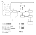
- FIG. 2 is a block diagram of the control configuration of the image acquisition device shown in FIG. 1.
- FIG. 3 is a diagram showing an example of a learning image acquired by the image acquisition device shown in FIG. 1.
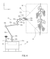
- FIG. 4 is a schematic diagram of a remotely controlled vehicle equipped with a robot arm device according to an embodiment of the present invention.
- FIG. 5 is a side view of the end effector included in the robot arm device shown in FIG. 4.
- FIG. 6 is a block diagram of the robot arm control device.
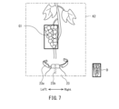
- FIG. 7 is a diagram showing an example of a recognition image acquired by the robot arm device shown in FIG. 6.
- FIG. 1 is a schematic diagram of an image acquisition device 31 according to an embodiment of the present invention.
- FIG. 2 is a block diagram of the control configuration of the image acquisition device 31 shown in FIG. 1.
- the arrow Front in the figure indicates the front direction of the imaging tool 32 and the end effector 23.
- the arrow Rear in the figure indicates the rear direction of the imaging tool 32 and the end effector 23.
- An arrow Up in the figure indicates the upward direction of the imaging tool 32 and the end effector 23.
- the arrow Down in the figure indicates the downward direction in the imaging tool 32 and the end effector 23.
- the front-back direction of the imaging tool 32 and the end effector 23 is a direction in which the photographing direction of the camera unit, which is the imaging tool 32 and the end effector 23, is the front direction of the imaging tool 32 and the end effector 23.
- the left-right direction of the imaging tool 32 and the end effector 23 is a direction perpendicular to the front-back direction and the up-down direction of the imaging tool 32 and the end effector 23, when the vertical direction is defined as the up-down direction.
- the image acquisition device 31 generates a learning image K1 (see FIG. 3) for image recognition processing of an object in a working device and a recognition image K2 (see FIG. 7) for image recognition processing for detecting an object in a working device.
- the working device is a robot arm device 20.
- the target object is the object to be treated by the working device.
- the robot arm device 20 harvests grapes as an object.
- the image acquisition device 31 includes a camera unit 24, an imaging device 32, a display device 36, a battery 37, a first imaging control section 11 as an imaging control section, a recording section 42, and a transmission section. 43.
- the camera unit 24 while attached to the imaging tool 32, captures a learning image K1 for use in machine learning. Further, the camera unit 24 captures a recognition image K2 for executing a detection task while being attached to the end effector 23 of the robot arm device 20.
- the camera unit 24 is a stereo camera that captures parallax images. Specifically, the camera unit 24 is configured by arranging two monocular cameras in the left-right direction of the imaging tool 32 in a state where the imaging direction is arranged along the front direction. The camera unit 24 functions as an imaging section.
- a monocular camera is a camera that images the grapes from a single viewpoint at a time.
- a monocular camera is a digital camera using an image sensor such as a CCD sensor or a COMOS sensor.
- the camera unit 24 generates a parallax image based on images captured by two monocular cameras.
- the camera unit 24 can be attached to and detached from the end effector 23 and the imaging device 32 via the base 24a, as shown by arrow T. That is, the camera unit 24 removed from the end effector 23 can be attached to the imaging tool 32.
- the operator can carry the imaging tool 32 to which the camera unit 24 is attached to any location in the field and capture the learning image K1. Further, the camera unit 24 removed from the imaging tool 32 can be attached to the end effector 23.
- the robot arm device 20 can capture the recognition image K2 using the camera unit 24 attached to the end effector 23.
- the imaging tool 32 is an instrument to which the camera unit 24 is attached and is used by the operator to carry and perform imaging operations.
- the imaging tool 32 includes a model 33, a grip 34, and a trigger button 35.
- the model 33 is a dummy that has the same shape and the same color as the end effector 23 of the robot arm device 20.
- the model 33 includes a dummy gripping device 33a that imitates the gripping device 23a of the end effector 23, and a dummy cutting device 33b that imitates the cutting device 23b.
- the states of the dummy gripping device 33a and the dummy cutting device 33b are set to be similar to the state of the end effector 23 at the time of starting control of the harvesting operation described above.
- the upper surface of the model 33 is configured such that the camera unit 24 can be supported via the base 24a.
- the camera unit 24 is arranged on the model 33 so that a part of the upper surface of the model 33 and a part of the dummy gripping device 33a of the model 33 are included within the viewing angle R1 of the camera unit 24.
- the angle of view refers to an angle that indicates the range that is actually imaged by the image sensor included in the camera unit 24. In this way, the camera unit 24 removed from the end effector 23 can be attached to the model 33.
- the positional relationship of the camera unit 24 with respect to the model 33 when the camera unit 24 is attached to the imaging device 32 is the same as the positional relationship of the camera unit 24 with respect to the end effector 23 when the camera unit 24 is attached to the robot arm device 20. . Therefore, the shape of the model 33, the position of the model 33, and the color of the model 33 shown in the learning image K1 taken by the camera unit 24 when attached to the model 33 are the same as when attached to the robot arm device 20.
- the shape, the position of the end effector 23, and the color of the end effector 23 shown in the recognition image K2 captured by the camera unit 24 are substantially the same.
- the grip 34 is connected to a model 33 that is held by the operator when carrying the imaging tool 32 and when performing imaging.
- the grip 34 is located behind the mounting position of the camera unit 24 on the model 33.
- the trigger button 35 is an operation button for capturing an image with the camera unit 24 attached to the model 33.
- a trigger button 35 is provided on the grip 34. Therefore, when the worker uses the image acquisition device 31 to capture an image, the worker can operate the trigger button 35 while holding the grip 34.
- the display device 36 displays the image captured by the camera unit 24.
- the display device 36 is attached to the grip 34 of the imaging tool 32.
- the display device 36 can be configured by a display device such as a liquid crystal display or an organic EL display.
- the display device 36 may include a tilt mechanism.
- the display device 36 may be attached to the grip 34 so as to be tiltable within a certain range in the front-rear direction.
- the battery 37 supplies electricity to each part of the camera unit 24 and the image acquisition device 31, which are connected via the connection line L1.
- the battery 37 can be placed inside the grip 34, for example.
- the imaging control unit is a device that controls the image acquisition device 31.
- the imaging control section may actually have a configuration in which a CPU, ROM, RAM, HDD, SSD, etc. are connected via a bus, or it may have a configuration consisting of a one-chip LSI or the like.
- the imaging control section stores various programs and data for controlling the operations of the camera unit 24, display device 36, recording section 42, and transmitting section 43 of the image acquisition device 31.
- the imaging control section includes a first imaging control section 11 that controls the camera unit 24 attached to the imaging tool 32, and a second imaging control section 12 that controls the camera unit 24 attached to the end effector 23.
- the first imaging control unit 11 is provided inside the model 33, for example.
- the first imaging control section 11 is electrically connected to the camera unit 24, the display device 36, the recording section 42, and the transmitting section 43. Further, the first imaging control section 11 is detachably connected to the camera unit 24 via a connection line L1.
- the learning image K1 is input to the first imaging control section 11 from the camera unit 24.
- the first imaging control section 11 outputs control signals to the camera unit 24, the display device 36, the recording section 42, and the transmitting section 43. Further, the first imaging control section 11 outputs the learning image K1 to the display device 36, the recording section 42, and the transmitting section 43.
- the second imaging control unit 12 is provided, for example, in the robot arm control device 25 of the robot arm device 20.
- the second imaging control section 12 is detachably connected to the camera unit 24 via a connection line L2.
- the second imaging control section 12 receives the recognition image K2 from the camera unit 24. Further, the second imaging control section 12 outputs a control signal to the camera unit 24.
- the recording unit 42 is a storage device that records the learning image K1.
- the recording unit 42 includes a main storage device, an auxiliary storage device, an external storage device, and the like.
- the recording section 42 is electrically connected to the first imaging control section 11.
- the recording unit 42 records the learning image K1 input from the first imaging control unit 11.
- the recording unit 42 is provided inside the model 33, for example.
- the transmitting unit 43 uploads the learning image K1 recorded in the recording unit 42 to the external server 60 via the communication network.
- the transmitting section 43 is electrically connected to the first imaging control section 11 and the recording section 42 .
- the timing of uploading by the transmitter 43 is arbitrary, and may be, for example, at regular intervals, at a user's instruction, or in real time.
- the transmitter 43 is provided inside the model 33, for example.
- FIG. 3 is a diagram showing an example of the learning image K1 acquired by the imaging device shown in FIG.
- the operator removes the connection line L2 from the camera unit 24 attached to the end effector 23 of the robot arm device 20. Furthermore, the operator removes the camera unit 24 from the end effector 23. The operator attaches the removed camera unit 24 to the model 33 of the imaging tool 32. Furthermore, the operator connects the connection line L1 to the camera unit 24. Thereby, the camera unit 24 switches from a state in which it can take an image in the robot arm device 20 to a state in which it can take an image in the imaging tool 32.
- the operator images the grapes with the camera unit 24 by operating the trigger button 35 provided on the grip 34 of the imaging tool 32.
- the first imaging control section 11 When the first imaging control section 11 detects the operation of the trigger button 35, it transmits a control signal instructing the camera unit 24 to take an image via the connection line L1. In response to this, the camera unit 24 images the grapes.
- the learning image K1 captured by the camera unit 24 may be in either a still image format or a moving image format. Further, the image format may be changed depending on the operation on the trigger button 35. For example, when the trigger button 35 is operated, the first imaging control section 11 outputs a control signal for capturing a still image to the camera unit 24. Further, the first imaging control section 11 outputs a control signal for imaging a moving image to the camera unit 24 when the trigger button 35 is kept pressed for a certain period of time or more.
- the worker images the grapes with the grapes included within the angle of view.
- the image acquisition device 31 is capable of capturing an image including a portion of the model 33 and the grapes while the operator is holding the imaging tool 32.
- the imaging tool 32 is configured to be portable by the operator. Therefore, the operator can move to any location in the field and photograph the grapes while carrying the imaging tool 32. Further, when photographing, the operator can operate the imaging tool 32 while checking the content of the image taken by the camera unit 24 on the display device 36.
- the camera unit 24 is arranged on the model 33 so that a part of the upper surface of the model 33 and a part of the dummy gripping device 33a of the model 33 are included within the viewing angle R1 of the camera unit 24.
- the camera unit 24 when the camera unit 24 is attached to the end effector 23 of the robot arm device 20, the camera unit 24 includes a portion of the upper surface of the end effector 23 and a gripping device 23a of the end effector 23 within the viewing angle R2 of the camera unit 24. is placed on the end effector 23 so as to include a part of it.
- the positional relationship between the camera unit 24 when attached to the model 33, the upper surface of the model 33, the dummy gripping device 33a, and the dummy cutting device 33b is the same as that of the camera unit 24 when attached to the end effector 23, , the positional relationship is the same as that of the gripping device 23a and the cutting device 23b.
- the learning image K1 captured by the camera unit 24 includes a portion of the upper surface of the model 33 and a portion of the gripping device 23a of the end effector 23 in addition to the grape LG1 as the object. It will be done.
- the shape of the dummy gripping device 33a is set in an open state.
- the dummy cutting device 33b indicated by a broken line is set in a backward state so that it does not appear within the viewing angle R1.
- the model 33 is formed to have the same shape as the end effector 23 of the robot arm device 20. Further, the model 33 is made of the same material and color as the end effector 23 of the robot arm device 20.
- the first imaging control section 11 acquires the learning image K1 captured as described above from the camera unit 24.
- the first imaging control unit 11 displays the acquired learning image K1 on the display device 36 and outputs it to the recording unit 42.
- the image acquisition device 31 may adjust the imaging conditions of the camera unit 24 using the image of the imaging device 32 included in the learning image K1 captured by the camera unit 24 attached to the imaging device 32. That is, the image acquisition device 31 can use the already captured learning image K1 to adjust the imaging conditions for the imaging to be performed from now on.
- a more specific explanation is as follows.
- the image captured by the camera unit 24 attached to the imaging device 32 includes an image of the model 33.
- the shape etc. of the model 33 are substantially the same as the end effector 23 that the robot arm device 20 has. Therefore, the shape, positional relationship, and color of the image of the model 33 in the image captured by the camera unit 24 attached to the imaging tool 32 are the same as the image of the end effector 23 in the image captured by the camera unit 24 attached to the end effector 23. The shape, positional relationship, and color are almost the same.
- the image acquisition device 31 uses the images of the model 33 included in the images captured under various conditions by the camera unit 24 attached to the imaging tool 32, so that the camera unit 24 can properly detect the grapes. You can calibrate exposure time, exposure, color tone, etc. Thereby, it is possible to obtain a learning image K1 that improves the recognition rate of grapes to be harvested by the robot arm device 20.
- the plurality of learning images K1 thus recorded in the recording unit 42 are uploaded from the imaging device 32 to the server 60.
- the external server 60 performs machine learning using the plurality of uploaded learning images K1 as teacher data to obtain a learned model.
- the trained model acquired in this manner is introduced into the robot arm control device 25 as a detection task used in image recognition processing in the robot arm control device 25.
- the learning image K1 is attached to an end effector 23 that is a part of the robot arm device 20 during work.
- An image that includes a part of the end effector 23 in the same positional relationship as the recognition image K2 captured by the camera unit 24 is preferable.
- the learning image K1 is preferably an image of grapes of various shapes taken under various conditions.
- the image acquisition device 31 includes a model 33 that is the same as a part of the end effector 23 that is always included in the recognition image K2, and a grape as an object.
- images captured under various conditions can be acquired as the learning image K1 for machine learning. Therefore, it can be used as a grape detection task in the robot arm device 20.
- the recognition rate of grapes in the recognition image K2 is improved. be able to.
- objects other than grapes that are reflected in images captured by the robot arm device 20 and the imaging device 32 are set to the same conditions not only in positional relationship but also in shape and color. Therefore, in the learning image K1 captured by the camera unit 24 attached to the imaging device 32, elements that reduce the recognition rate in machine learning are suppressed. Thereby, it is possible to obtain a learning image K1 that improves the recognition rate of grapes to be harvested by the robot arm device 20.
- the image capturing device 32 when the image capturing device 32 captures an image with the attached camera unit 24, it records the captured image in the recording unit 42. Further, the imaging device 32 transmits the captured learning image K1 to an external server 60 that performs machine learning using the transmitting unit 43. Therefore, the image acquisition device 31 can easily use a plurality of images captured by the imaging tool 32 under various conditions as the learning image K1 for machine learning. In this way, it is possible to obtain the learning image K1 that improves the recognition rate of the grapes to be harvested by the robot arm device 20.
- the camera unit 24 attached to the imaging tool 32 when performing the harvesting work is attached to the end effector 23 that is a part of the robot arm device 20.
- the robot arm device 20 performs the harvesting operation using the introduced detection task.
- FIG. 4 is a schematic diagram of a robot arm device 20 according to an embodiment of the present invention.
- FIG. 5 is a side view of the end effector according to the embodiment of the invention.
- FIG. 6 is a block diagram of the robot arm control device 25.
- FIG. 7 is a diagram showing an example of a recognition image K2 acquired by the robot arm device shown in FIG. 6.
- the robot arm device 20 performs the work of harvesting grapes, for example, as a target object.
- the robot arm device 20 is a working device for harvesting grapes in a field.
- the robot arm device 20 performs image recognition processing on the image captured by the camera unit 24 to harvest detected grapes.
- the image recognition process is performed using a detection task obtained through machine learning.
- the learning image K1 acquired by the image acquisition device 31 is used as teacher data in the machine learning of the image recognition process.
- a trained model that can be obtained by the machine learning is used as a detection task in the image recognition process.
- the robot arm device 20 harvests the detected grapes using the end effector 23.
- the robot arm device 20 includes a vehicle device 2, an articulated robot arm 21, an end effector 23, an image acquisition device 31, and a robot arm control device 25.
- the vehicle device 2 is a device that travels to a predetermined location by remote control using an external control signal or by automatically driving along a set route.
- the vehicle device 2 is illustratively configured as a four-wheeled vehicle.
- the multi-joint robot arm 21 in this embodiment is a serial link mechanism robot arm in which the links are connected in series from the base end 21a to the distal end 21b by a rotary joint with one degree of freedom.
- the multi-joint robot arm 21 is, for example, a vertical multi-joint robot arm having a movable part with six degrees of freedom.
- the articulated robot arm 21 is provided on the remotely operated vehicle 1.
- the multi-joint robot arm 21 has a plurality of links 22a and a plurality of rotation joints 22b.
- the rotary joint 22b has an actuator (not shown) that drives the link 22a.
- the actuator includes, for example, a motor.
- the rotation joint 22b is driven by the robot arm control device 25.
- the multi-joint robot arm 21 configured in this way can move the end effector 23 fixed to the output shaft of the motor unit of the tip part 21b to any position within the movable space of the multi-joint robot arm 21 with six degrees of freedom. It can be moved and placed in any position.
- the configuration of the multi-joint robot arm 21 is similar to that of a general multi-joint robot arm. Therefore, detailed explanation of the multi-joint robot arm 21 will be omitted. Note that the configuration of the articulated robot arm 21 is not limited to the configuration described in each figure as long as it is configured to be able to work on grapes.
- the end effector 23 is a device that works on grapes.
- the end effector 23 according to the embodiment of the present invention is a collecting device that collects grapes.
- the end effector 23 is fixed to the distal end portion 21b of the multi-joint robot arm 21.
- the end effector 23 includes a gripping device 23a that grips agricultural products and a cutting device 23b that separates the agricultural products from branches and stems.
- the gripping device 23a is configured such that the claw portion can be opened and closed in the left-right direction.
- the cutting device 23b is configured to be able to move forward and backward.
- the gripping device 23a and the cutting device 23b are driven by, for example, a motor.
- the end effector 23 harvests grapes by cutting the stems closer to the trunk than the gripping position with a cutting device 23b while gripping the stems of grapes to be harvested with a gripping device 23a.
- the gripping device 23a is set to the open state, and the cutting device 23b is set to the retracted state.
- the gripping device 23a grips the stems of grapes to be harvested, the gripping device 23a is in a closed state. With the gripping device 23a gripping the stems of grapes to be harvested, the cutting device 23b moves forward to cut the stems on the trunk side of the grapes.
- the image acquisition device 31 includes a camera unit 24 and a second imaging control section 12.
- the second imaging control unit 12 is provided, for example, in the robot arm control device 25 of the robot arm device 20.
- the camera unit 24 captures a recognition image K2 for executing a detection task while being attached to the robot arm device 20. As described above, the recognition image K2 captured by the camera unit 24 is generated based on the parallax image.
- the camera unit 24 is supported on the upper surface of the end effector 23 via the base 24a. By removing the base 24a from the top surface of the end effector 23, the camera unit 24 can be removed from the end effector 23. The camera unit 24 removed from the end effector 23 can be attached to the imaging tool 32 as described above.
- the camera unit 24 is arranged to capture an image in front of the end effector 23 in a range of an angle of view R2.
- the camera unit 24 is arranged on the end effector 23 so that a part of the upper surface of the end effector 23 and a part of the gripping device 23a of the end effector 23 are included within the field of view R2 of the camera unit 24, as shown in FIG. ing.
- connection line L2 of the camera unit 24 extends to the rear of the end effector 23. That is, the connection line L2 of the camera unit 24 is arranged outside the range of the angle of view R2. Note that the connection line L2 is electrically connected to the camera unit 24 and the second imaging control section 12 of the robot arm control device 25. The connection line L2 is detachably connected to the camera unit 24.
- the connection line L2 includes a power line for transmitting electricity from the robot arm control device 25 to the camera unit 24 and a signal line for transmitting control signals between the camera unit 24 and the robot arm control device 25.
- the robot arm control device 25 is a device that controls the multi-joint robot arm 21, the end effector 23, and the camera unit 24.
- the robot arm control device 25 may actually have a configuration in which a CPU, ROM, RAM, HDD, SSD, etc. are connected via a bus, or it may consist of a one-chip LSI or the like. It may be a configuration.
- the robot arm control device 25 stores various programs and data for controlling the operations of the multi-joint robot arm 21, camera unit 24, and end effector 23.
- the robot arm control device 25 includes a second imaging control section 12 as an imaging control section that constitutes the image acquisition device 31, an image recognition processing section 27, and a drive control section 28.
- the drive control unit 28 is a control device that controls the motor of the end effector 23 and the motor unit of each axis of the articulated robot arm 21. It is connected to each axis of the articulated robot arm 21 and to the drive circuit of the motor included in the motor unit of the gripping device 23a and cutting device 23b of the end effector 23, and can transmit a control signal to the motor drive circuit. Further, the drive control section 28 can obtain rotational position information (encoder signal) of the motor from the motor unit. The drive control unit 28 can arrange the end effector 23 at any position and in any posture using the articulated robot arm 21.
- the second imaging control section 12 is connected to the camera unit 24 via the connection line L2, and acquires the recognition image K2 captured by the camera unit 24.
- the second imaging control unit 12 outputs the acquired recognition image K2 to the image recognition processing unit 27.
- the image recognition processing unit 27 performs image recognition processing of grapes based on the recognition image K2. That is, the image recognition processing unit 27 is a control device that executes a detection task of detecting grapes G1 (hereinafter simply referred to as "target grapes G1") that are targets of harvesting work from the recognition image K2.
- the image recognition processing unit 27 outputs the coordinate information and distance information of the target grape G1 detected by the detection task to the drive control unit 28.
- the drive control unit 28 moves the end effector 23 relative to the target grape G1 based on the coordinate information output by the image recognition processing unit 27, and controls the drive circuits of the motors of the gripping device 23a and cutting device 23b in the end effector 23. Send control signals.
- the robot arm control device 25 can perform the harvesting operation of the target grapes G1 using the end effector 23.
- the robot arm control device 25 is communicably connected to the communication device 7, and can acquire control signals received by the communication device 7 from the outside. Further, the robot arm control device 25 can continuously transmit the control signal generated by the robot arm control device 25 or the recognition image K2 captured by the camera unit 24 to the outside via the communication device 7.
- the image acquisition device 31 includes the camera unit 24 as an imaging section provided in the robot arm device 20 as a working device that performs work on the target grape G1 as a target object, and the imaging unit 24 in the camera unit 24. and an imaging control section that controls the imaging control section.
- the image acquisition device 31 also includes an imaging tool 32 that includes a model 33 of the end effector 23 that is part of the robot arm control device 25.
- the imaging tool 32 can be carried by the operator.
- the camera unit 24 can be attached to and detached from the robot arm device 20 and the imaging device 32, respectively. Further, the positional relationship of the camera unit 24 with respect to the model 33 when attached to the imaging tool 32 is the same as the positional relationship with respect to the robot arm device 20 when attached to the robot arm device 20. Further, the camera unit 24 is configured to be attachable to the imaging tool 32 so that a part of the model 33 is included in the image captured by the camera unit 24.
- the recognition rate of the target grape G1 to be harvested by the robot arm device 20 is improved. can be done.
- the robot arm device 20 is harvesting target grapes G1, which are agricultural crops.
- the robot arm device can be used not only for harvesting crops outdoors, but also for handling industrial parts outdoors, depending on the type of end effector attached to the articulated robot arm, whether outdoors or indoors. A configuration may also be used in which this is implemented.
- the end effector 23 has a gripping device 23a having a specific opening/closing structure and a cutting device 23b having a specific advancing/retracting structure.
- the end effector may have any configuration as long as it performs work on the object.
- the gripping device 23a of the end effector 23 is in the open state and the cutting device 23b is in the retracted state.
- the end effector may have a gripping device in a closed state.
- the end effector may have a cutting device in an advanced state.
- the camera unit 24 attached to the multi-joint robot arm 21 is arranged so that a part of the upper surface of the end effector 23 and a part of the gripping device 23a are included in the angle of view R2 of the camera unit 24. It is located at 23.
- the camera unit only needs to be capable of capturing an image of a model having the same appearance as the end effector when the articulated robot arm 21 starts controlling the harvesting operation when it is attached to the imaging tool.
- the dummy gripping device 33a and the dummy cutting device 33b of the imaging tool 32 may be able to change the state in the same way as the gripping device 23a and the cutting device 23b. That is, the dummy gripping device may be configured such that the claw portion can be opened and closed. Further, the dummy cutting device may be configured to be able to move forward and backward. Further, a portion of the image acquisition device 31 that does not fall within the viewing angle R1 of the camera unit 24 may be omitted. For example, in the embodiment, the dummy cutting device 33b corresponds to a portion that does not fall within the viewing angle R1 of the camera unit 24. Therefore, in the embodiment described above, the dummy cutting device 33b may be omitted.
- the camera unit 24 is a stereo camera configured by combining monocular cameras.
- the camera unit may be a stereo camera configured by housing a pair of optical lenses and an image sensor in one housing.
- the camera unit is not limited to a stereo camera, and may be a single monocular camera.
- the camera unit 24 attached to the robot arm device 20 generates a parallax image based on images captured by two monocular cameras.
- the camera unit may also be configured to transmit images captured by two monocular cameras to the robot arm control device.
- the robot arm control device may generate a parallax image based on the image transmitted from the camera unit.
- the robot arm control device 25 may measure the distance to the target grape G1 from the parallax image acquired by the camera unit 24.
- the robot arm device may measure the distance to the target grapes using a distance measuring sensor or the like instead of using the camera unit.
- the image acquisition device 31 acquires a parallax image as the learning image K1.
- the camera unit may be a single monocular camera that captures an image from a single viewpoint as a learning image.
- the camera unit 24 is attached to a six-axis articulated robot arm 21 that is a working device.
- the working device is not limited to the articulated robot arm 21.
- the working device may be, for example, an unmanned aerial vehicle, a machine tool, or the like.
- the imaging tool 32 has a grip for the operator to hold.
- the imaging device may include a moving body for moving the camera unit. That is, the imaging device may be realized as a moving body, or may have a configuration in which a model is attached to the moving body.
- the image acquisition device 31 performs imaging using the camera unit 24 attached to the imaging device 32 in response to an input event to the trigger button 35.
- the image acquisition device may include a touch input unit that receives touch input on the display device, and the camera unit 24 may capture an image in response to the touch input on the display device.
- the image acquisition device 31 includes a display device 36.
- the image acquisition device may not have a display device.
- the image acquisition device may accept an operation from a mobile terminal, and may take an image using a camera unit in accordance with the received operation.
- the image acquisition device 31 includes a recording section 42 and a transmitting section 43.
- the image acquisition device does not need to have a recording section or a transmitting section.
- the image acquisition device 31 transmits the captured learning image K1 to the server 60.
- “Transmission” here includes sending the learning images from the image acquisition device to an external server via a wired network, sending them via a wireless network, and sending them to an external server such as a USB memory.
- the server 60 executes machine learning based on the learning image K1.
- the image acquisition device may perform machine learning based on the learning images using the first imaging control section.
- the image acquisition device 31 attaches the camera unit 24 to the end effector 23 of the robot arm device 20 or the model 33 of the image acquisition device 31 to image the grapes.
- the image acquisition device may have a configuration in which the end effector is removed together with the camera unit from the articulated robot arm, and the end effector to which the camera unit is attached is attached to the imaging tool.
- the camera unit 24 is attached to the imaging device 32 by removing the connection line L2 from the camera unit 24 attached to the end effector 23 of the robot arm device 20, but the present invention is not limited to this.
- a camera unit with the same specifications as the camera unit scheduled to be mounted on the robot arm device may be attached to the imaging device.
- external communication destinations with which the robot arm control device 25 communicates via the communication device 7 are not particularly limited, but may include, for example, the server 60 and an operating terminal for operating the robot arm device. be. Further, there is no particular restriction on the communication method.
- First imaging control section 12 Second imaging control section 20
- Robot arm device 21 Multi-joint robot arm 23
- End effector 24 Camera unit 25
- Robot arm control device 23a Gripping device 23b
- Cutting device 27
- Image recognition processing section 28
- Drive control section 31
- Image acquisition Device 32
- Model 42 Recording unit 43 Transmitting unit 60 Server G1 Target grapes
Landscapes
- Physics & Mathematics (AREA)
- General Physics & Mathematics (AREA)
- Engineering & Computer Science (AREA)
- Theoretical Computer Science (AREA)
- Manipulator (AREA)
Abstract
ロボットアーム制御装置25によって作業される対象物の認識率を向上させる学習用画像を取得可能な画像取得装置31を得る。画像取得装置31は、対象物に対して作業を行うロボットアーム制御装置25に設けられ、前記対象物とロボットアーム制御装置25の一部とを含む画像を撮像するカメラユニット24と、カメラユニット24における撮像を制御する撮像制御部とを有する。撮像具32は、ロボットアーム制御装置25の少なくとも一部の模型33を含み、作業者が持ち運び可能である。カメラユニット24は、ロボットアーム制御装置25と撮像具32とにそれぞれ着脱可能である。また、カメラユニット24は、模型33に対する位置関係がロボットアーム制御装置25に対する位置関係と同じ位置関係で且つ模型33の一部がカメラユニット24によって撮像される画像に含まれるように、撮像具32に取り付けられている。
Description
本発明は、画像取得装置に関する。
イチゴ、ぶどう等の果物、アスパラガス、トマト等の緑黄色野菜は、米、小麦等の穀物に比べてデリケートで損傷し易く、且つ単価が高い。このようなデリケートで単価が高い作物は、収穫時に損傷しないように一つずつ手作業で収穫される。従って、前記果物、前記緑黄色野菜等の収穫は、コンバイン等の収穫作業機械を用いた効率的で大規模な収穫が可能な穀物等に比べて生産者の肉体的負担が大きい。肉体的負担が大きい収穫作業のため、労働力の確保は難しく、生産者の負担が増大する傾向にある。
そこで、多関節ロボットアームを用いた作物の収穫システムが知られている。前記作物の収穫システムには、前記多関節ロボットアームの先端に作物を収穫するための作業装置及び画像処理部等が設けられている。前記収穫システムは、前記画像処理部によって収穫の対象となる作物の位置を特定し、前記作業装置によって収穫作業を行う。ところで、前記作物は、個別の形状及び実っている状況等が全て異なっている。よって、前記画像処理部では、前記作物の形状、実っている状況及び圃場の天候等の影響により、作物を適切に検出できない場合がある。
そこで、作物を収穫する条件下で前記作物を撮像した学習用画像を教師データとして、対象物の識別率を向上する識別方法が知られている。特許文献1に記載されている深層学習に基づくトマトの識別方法は、対象物であるトマトを栽培している屋外の自然光の下で撮像したトマトの画像を学習用画像として深層学習を行う。この際、トマトの画像は、可能な限り異なる条件の画像を学習用画像とする。トマトの画像は、例えば、撮像時の天候、時間、撮像時の角度、トマトの形状等が異なる画像、複数のトマトが含まれている画像、トマト以外のものが含まれている画像等が含まれる。このような学習用画像を使用することにより、複雑な条件下でのトマトの認識率を向上させている。
ところで、特許文献1のトマトの識別方法は、画像認識によって判別したトマトを摘み取るトマト摘み取りロボット等にも適用される。しかし、トマト摘み取りロボットが収穫する際に取得する画像には、トマトを摘み取るエンドエフェクタ等が常に含まれている場合が多い。一方、前記トマトの識別方法において作業者等が撮像装置によって撮像した学習用画像には、エンドエフェクタ等の画像が含まれていない。このようなエンドエフェクタ等の画像が含まれていない画像を学習用画像とした場合、トマト摘み取りロボットが収穫する際に取得する画像に含まれるエンドエフェクタ等がトマトの認識率を低下させる要因となる。また、トマト摘み取りロボットを使用してエンドエフェクタ等の画像が含まれる教師データを収集するには、多大な時間と労力が必要になり現実的でない。
本発明は、作業装置によって作業される対象物の認識率を向上させる学習用画像を取得可能な画像取得装置の提供を目的とする。
本発明者らは、作業装置によって作業される対象物の認識率を向上させる学習用画像を取得可能な画像取得装置について検討した。鋭意検討の結果、本発明者らは、以下のような構成に想到した。
本発明の一実施形態に係る画像取得装置は、対象物に対して作業を行う作業装置に設けられ、前記対象物と前記作業装置の一部とを含む画像を撮像する撮像部と、前記撮像部における撮像を制御する撮像制御部とを有する画像取得装置であって、前記作業装置の少なくとも一部の模型を含む、作業者が持ち運び可能な撮像具を有し、前記撮像部は、前記作業装置と前記撮像具とにそれぞれ着脱可能であって、前記撮像具に取り付けた場合の前記模型に対する位置関係が前記作業装置に取り付けた場合の前記作業装置に対する位置関係と同じ位置関係で且つ前記模型の一部が前記撮像部によって撮像される画像に含まれるように、前記撮像具に取り付け可能に構成されている。
上述のように、前記画像取得装置は、前記撮像具に取り付けられた前記撮像部によって前記模型と前記対象物とを含む画像を取得することができる。前記画像取得装置は、前記撮像具に前記撮像部を取り付けることにより、実際に前記作業装置が作業を行う現場において、作業者によって様々な条件での前記対象物の画像を取得することができる。また、前記画像取得装置は、前記撮像具に取り付けた前記撮像部によって前記対象物を撮像することにより、前記作業装置に取り付けられた前記撮像部が撮像した画像おける前記作業装置の位置と略等しい位置に前記模型が位置する画像を取得することができる。
ところで、前記作業装置が前記対象物に対して作業を行う時に、教師データを用いた機械学習によって画像を検出する場合、前記教師データの学習用画像は、作業時に前記撮像部によって撮像される画像と同じ位置関係で前記作業装置の一部を含む画像が好ましい。また、前記学習用画像は、様々な条件において様々な形状の対象物を撮像した画像が好ましい。よって、前記画像取得装置は、前記模型を含み、様々な条件下で撮像した好ましい画像を機械学習用の学習用画像として取得することができる。
これにより、作業装置によって作業される対象物の認識率を向上させる学習用画像を取得できる。
他の観点によれば、本発明の画像取得装置は、以下の構成を含むことが好ましい。前記撮像具は、前記撮像部が撮像した画像を保存する記録部と、前記記録部に保存された画像を外部に送信する送信部と、を有する。
上述のように、撮像具は、取り付けられた撮像部によって撮像した際、撮像した画像を記録部に記録する。さらに、前記撮像具は、前記撮像した画像を送信部によって機械学習を行う外部のサーバーに送信する。よって、前記画像処理装置は、撮像具によって様々な条件下で機械学習用の学習用画像を容易に撮像することができる。
これにより、作業装置によって作業される対象物の認識率を向上させる学習用画像を取得できる。
他の観点によれば、本発明の画像取得装置は、以下の構成を含むことが好ましい。前記模型は、前記作業装置と同一の形状且つ同一の色によって構成されている。
上述のように、撮像具に取り付けられた撮像部が撮像した画像には、作業装置の少なくとも一部の模型の画像が含まれている。前記模型の形状は、作業装置の形状と略同一且つ同一の色である。よって、前記撮像具に取り付けられた撮像部が撮像した画像における前記模型の画像の形状、位置関係及び色は、前記作業装置に取り付けられた撮像装置が撮像した画像における作業装置の画像の形状、位置関係及び色と略同一である。したがって、前記撮像具に取り付けられた前記撮像部によって撮像された画像には、機械学習において認識率を低下させる要素が抑制される。
これにより、作業装置によって作業される対象物の認識率を向上させる学習用画像を取得できる。
他の観点によれば、本発明の画像取得装置は、以下の構成を含むことが好ましい。前記撮像制御部は、前記撮像具に取り付けられた前記撮像部が撮像した画像に含まれる前記撮像具の画像を用いて、前記撮像部の撮像条件を調整する。
上述のように、撮像具に取り付けられた撮像部が撮像した画像には、作業装置の少なくとも一部の模型の画像が含まれている。前記模型の形状は、作業装置と略同一である。よって、前記撮像具に取り付けられた撮像部が撮像した画像における前記模型の画像の形状、位置関係は、前記作業装置に取り付けられた撮像装置が撮像した画像における作業装置の画像の形状、位置関係と略同一である。したがって、前記画像取得装置は、前記撮像具に取り付けられた前記撮像部によって様々な条件下で撮像された画像に含まれる前記模型の画像を用いて、適正に前記対象物を検出できるように前記撮像部の露出時間、露光、色調等のキャリブレーションを行うことができる。
これにより、作業装置によって作業される対象物の認識率を向上させる学習用画像を取得できる。
本明細書で使用される専門用語は、特定の実施例のみを定義する目的で使用されるのであって、前記専門用語によって発明を制限する意図はない。
本明細書で使用される「及び/または」は、一つまたは複数の関連して列挙された構成物のすべての組み合わせを含む。
本明細書において、「含む、備える(including)」「含む、備える(comprising)」または「有する(having)」及びそれらの変形の使用は、記載された特徴、工程、操作、要素、成分、及び/または、それらの等価物の存在を特定するが、ステップ、動作、要素、コンポーネント、及び/または、それらのグループのうちの1つまたは複数を含むことができる。
本明細書において、「取り付けられた」、「接続された」、「結合された」、及び/または、それらの等価物は、広義の意味で使用され、“直接的及び間接的な”取り付け、接続及び結合の両方を包含する。さらに、「接続された」及び「結合された」は、物理的または機械的な接続または結合に限定されず、直接的または間接的な電気的接続または結合を含むことができる。
他に定義されない限り、本明細書で使用される全ての用語(技術用語及び科学用語を含む)は、本発明が属する技術分野の当業者によって一般的に理解される意味と同じ意味を有する。
一般的に使用される辞書に定義された用語は、関連する技術及び本開示の文脈における意味と一致する意味を有すると解釈されるべきであり、本明細書で明示的に定義されていない限り、理想的または過度に形式的な意味で解釈されることはない。
本発明の説明においては、いくつもの技術及び工程が開示されていると理解される。これらの各々は、個別の利益を有し、他に開示された技術の1つ以上、または、場合によっては全てと共に使用することもできる。
したがって、明確にするために、本発明の説明では、不要に個々のステップの可能な組み合わせをすべて繰り返すことを控える。しかしながら、本明細書及び特許請求の範囲は、そのような組み合わせがすべて本発明の範囲内であることを理解して読まれるべきである。
本明細書では、本発明に係る画像取得装置の実施形態について説明する。
以下の説明では、本発明の完全な理解を提供するために多数の具体的な例を述べる。しかしながら、当業者は、これらの具体的な例がなくても本発明を実施できることが明らかである。
よって、以下の開示は、本発明の例示として考慮されるべきであり、本発明を以下の図面または説明によって示される特定の実施形態に限定することを意図するものではない。
[作業装置]
本明細書において、作業装置とは、エンドエフェクタによって対象物に前記処置を行うために前記エンドエフェクタを所定の位置まで移動させる機械を意味する。作業装置は、例えば、ロボットアーム、無人飛行体、無人地上車両等、前記エンドエフェクタを移動させることが可能な装置であればよい。
本明細書において、作業装置とは、エンドエフェクタによって対象物に前記処置を行うために前記エンドエフェクタを所定の位置まで移動させる機械を意味する。作業装置は、例えば、ロボットアーム、無人飛行体、無人地上車両等、前記エンドエフェクタを移動させることが可能な装置であればよい。
[エンドエフェクタ]
本明細書において、エンドエフェクタとは、対象物に対して任意の処置を行う装置を意味する。前記エンドエフェクタは、多関節ロボットアーム等の作業装置の先端に取り付けられる。前記エンドエフェクタは、前記対象物に対する処置に応じた構造を有し、前記処置に応じた様々な機器を有している。
本明細書において、エンドエフェクタとは、対象物に対して任意の処置を行う装置を意味する。前記エンドエフェクタは、多関節ロボットアーム等の作業装置の先端に取り付けられる。前記エンドエフェクタは、前記対象物に対する処置に応じた構造を有し、前記処置に応じた様々な機器を有している。
[対象物]
本明細書において、対象物とは、前記エンドエフェクタによって処置を行う対象である自然物、人工物、ウイルス、生物(動物、植物)等を意味する。対象物は、具体的には農作物、海産物、工業製品、家畜、昆虫、人等を意味する。前記対象物は、前記エンドエフェクタによって処置される部分である処置部位と処置位置に移動させるために前記接触部が接触する前記接触位置の両方を含む物である。前記対象物は、例えば、農作物における果柄、果実、幹、茎、枝、葉、柄及び生物等を含む。
本明細書において、対象物とは、前記エンドエフェクタによって処置を行う対象である自然物、人工物、ウイルス、生物(動物、植物)等を意味する。対象物は、具体的には農作物、海産物、工業製品、家畜、昆虫、人等を意味する。前記対象物は、前記エンドエフェクタによって処置される部分である処置部位と処置位置に移動させるために前記接触部が接触する前記接触位置の両方を含む物である。前記対象物は、例えば、農作物における果柄、果実、幹、茎、枝、葉、柄及び生物等を含む。
[撮像部]
本明細書において、撮像部とは、単眼カメラ及びステレオカメラ等の各種の撮像装置を含む撮像器具を意味する。また、撮像部は、画像取得装置及び撮像具の両方に着脱可能である。
本明細書において、撮像部とは、単眼カメラ及びステレオカメラ等の各種の撮像装置を含む撮像器具を意味する。また、撮像部は、画像取得装置及び撮像具の両方に着脱可能である。
[画像取得装置]
本明細書において、画像取得装置とは、前記作業装置が前記対象物を検出するのに用いられる検出タスクの機械学習用の画像及び前記作業装置が対象物に対して作業を行う際に前記対象物を検出するための画像を取得するものである。すなわち、画像取得装置が取得する画像は、機械学習用の学習用画像として用いられる。教師データとしての学習用画像による機械学習を行うことによって獲得できる学習済みモデルが上記検出タスクに相当する。
本明細書において、画像取得装置とは、前記作業装置が前記対象物を検出するのに用いられる検出タスクの機械学習用の画像及び前記作業装置が対象物に対して作業を行う際に前記対象物を検出するための画像を取得するものである。すなわち、画像取得装置が取得する画像は、機械学習用の学習用画像として用いられる。教師データとしての学習用画像による機械学習を行うことによって獲得できる学習済みモデルが上記検出タスクに相当する。
[撮像具]
本明細書において、撮像具は、作業者が持ち運び可能な器具である。撮像具は、前記作業装置の少なくとも一部の模型を含む。また、撮像具には、撮像部を取り付けたり取り外したりできる。撮像部が取り付けられた撮像具は、前記撮像部を用いて対象物を撮像することができる。
本明細書において、撮像具は、作業者が持ち運び可能な器具である。撮像具は、前記作業装置の少なくとも一部の模型を含む。また、撮像具には、撮像部を取り付けたり取り外したりできる。撮像部が取り付けられた撮像具は、前記撮像部を用いて対象物を撮像することができる。
本発明の一実施形態によれば、作業装置によって作業される対象物の認識率を向上させる学習用画像を取得できる。
以下で、各実施形態について、図面を参照しながら説明する。各図において、同一部分には同一の符号を付して、その同一部分の説明は繰り返さない。なお、各図中の構成部材の寸法は、実際の構成部材の寸法及び各構成部材の寸法比率等を忠実に表したものではない。
<実施形態>
(画像取得装置の全体構成)
図1及び図2を用いて本発明の実施形態に係る画像取得装置の全体構成を説明する。図1は、本発明の実施形態に係る画像取得装置31の模式図である。図2は、図1に示す画像取得装置31の制御構成のブロック図である。
(画像取得装置の全体構成)
図1及び図2を用いて本発明の実施形態に係る画像取得装置の全体構成を説明する。図1は、本発明の実施形態に係る画像取得装置31の模式図である。図2は、図1に示す画像取得装置31の制御構成のブロック図である。
以下、図中の矢印Frontは、撮像具32及びエンドエフェクタ23の前方向を示す。図中の矢印Rearは、撮像具32及びエンドエフェクタ23の後方向を示す。図中の矢印Upは、撮像具32及びエンドエフェクタ23の上方向を示す。図中の矢印Downは、撮像具32及びエンドエフェクタ23における下方向を示す。撮像具32及びエンドエフェクタ23の前後方向は、撮像具32及びエンドエフェクタ23であるカメラユニットの撮影方向を撮像具32及びエンドエフェクタ23の前方向とした方向である。また、撮像具32及びエンドエフェクタ23の左右方向は、鉛直方向を上下方向と規定した場合に、撮像具32及びエンドエフェクタ23の前後方向及び上下方向に垂直な方向である。
画像取得装置31は、作業装置における対象物の画像認識処理のための学習用画像K1(図3参照)及び作業装置における対象物を検出する画像認識処理のための認識用画像K2(図7参照)を取得するためのものである。本実施形態において、作業装置は、ロボットアーム装置20とする。対象物とは作業装置が処置を行う対象とするものである。以下では、ロボットアーム装置20が対象物として葡萄を収穫する場合について説明する。
画像取得装置31は、具体的には、カメラユニット24と、撮像具32と、表示装置36と、バッテリー37と、撮像制御部としての第1撮像制御部11と、記録部42と、送信部43とを備える。
カメラユニット24は、撮像具32に取り付けられた状態において、機械学習に用いるための学習用画像K1を撮像する。また、カメラユニット24は、ロボットアーム装置20のエンドエフェクタ23に取り付けられた状態において、検出タスクを実行するための認識用画像K2を撮像する。カメラユニット24は、視差画像を撮像するステレオカメラである。カメラユニット24は、具体的には、2つの単眼カメラを、撮像方向が前方向に沿うように配置された状態で撮像具32の左右方向に配置して構成される。カメラユニット24は、撮像部として機能する。単眼カメラは、一度に単一視点から葡萄を撮像するカメラである。単眼カメラは、CCDセンサ又はCOMOSセンサ等の撮像素子を用いたデジタルカメラである。カメラユニット24は、2つの単眼カメラにより撮像された画像に基づいて視差画像を生成する。
カメラユニット24は、矢印Tに示すようにエンドエフェクタ23と撮像具32とにベース24aを介してそれぞれ着脱可能である。すなわち、エンドエフェクタ23から取り外したカメラユニット24は、撮像具32に取り付けることができる。作業者は、カメラユニット24を取り付けた撮像具32を圃場の任意の場所に持ち運んで学習用画像K1を撮像することができる。また、撮像具32から取り外したカメラユニット24は、エンドエフェクタ23に取り付けることができる。ロボットアーム装置20は、エンドエフェクタ23に取り付けたカメラユニット24によって認識用画像K2を撮像することができる。
撮像具32は、カメラユニット24を取り付けて、作業者が持ち運び及び撮像操作を行うための器具である。撮像具32は、模型33と、グリップ34と、トリガーボタン35と、を含む。
模型33は、ロボットアーム装置20のエンドエフェクタ23と同一の形状且つ同一の色によって構成されたダミーである。模型33は、エンドエフェクタ23の把持装置23aを模したダミー把持装置33aと、切断装置23bを模したダミー切断装置33bとを含む。ダミー把持装置33a及びダミー切断装置33bの状態は、上述した収穫作業の制御の開始時のエンドエフェクタ23の状態と同様に設定されている。模型33の上面は、カメラユニット24がベース24aを介して支持可能に構成される。カメラユニット24は、カメラユニット24の画角R1内に模型33の上面の一部及び模型33のダミー把持装置33aの一部が含まれるように模型33に配置される。なお、画角とは、カメラユニット24に含まれる撮像素子に実際に撮像される範囲を示す角度を意味する。このように、エンドエフェクタ23から取り外したカメラユニット24は、模型33に取り付けることができる。
カメラユニット24を撮像具32に取り付けた場合の模型33に対するカメラユニット24の位置関係は、カメラユニット24をロボットアーム装置20に取り付けた場合のエンドエフェクタ23に対するカメラユニット24の位置関係と同一である。よって、模型33に取り付けられた状態でカメラユニット24が撮像した学習用画像K1に写っている模型33の形状、模型33の位置及び模型33の色は、ロボットアーム装置20に取り付けられた状態でカメラユニット24が撮像した認識用画像K2に写っているエンドエフェクタ23の形状、エンドエフェクタ23の位置及びエンドエフェクタ23の色と略同一になる。
グリップ34は、作業者が撮像具32を持ち運ぶ場合及び撮像を行う場合に作業者が把持する模型33に接続されている。グリップ34は、模型33におけるカメラユニット24の取り付け位置よりも後方に位置している。
トリガーボタン35は、模型33に取り付けられたカメラユニット24によって撮像を行うための操作ボタンである。トリガーボタン35は、グリップ34に設けられている。このため、作業者が画像取得装置31を用いて撮像を行う場合には、作業者はグリップ34を握ったままトリガーボタン35に対する操作を行うことができる。
表示装置36は、カメラユニット24によって撮像された画像を表示する。表示装置36は、撮像具32のグリップ34に取り付けられている。表示装置36は、液晶ディスプレイ及び有機EL等の表示装置により構成することができる。表示装置36は、チルト機構を備えていてもよい。例えば、表示装置36は、グリップ34に対して、前後方向の一定範囲において傾斜可能に取り付けられていてもよい。
バッテリー37は、接続線L1で接続されているカメラユニット24及び画像取得装置31の各部に電気を供給する。バッテリー37は、例えば、グリップ34の内部に配置することができる。
撮像制御部は、画像取得装置31を制御する装置である。撮像制御部は、実体的には、CPU、ROM、RAM、HDD、SSD等がバスで接続された構成であってもよく、あるいはワンチップのLSI等からなる構成であってもよい。撮像制御部には、画像取得装置31のカメラユニット24、表示装置36、記録部42、送信部43の動作を制御するために種々のプログラムやデータが格納されている。撮像制御部は、撮像具32に取り付けられたカメラユニット24を制御する第1撮像制御部11と、エンドエフェクタ23に取り付けられたカメラユニット24を制御する第2撮像制御部12とを有する。
第1撮像制御部11は、例えば、模型33の内部に設けられている。第1撮像制御部11は、カメラユニット24、表示装置36、記録部42及び送信部43と電気的に接続されている。また、第1撮像制御部11は、カメラユニット24と接続線L1を介して着脱可能に接続されている。第1撮像制御部11は、カメラユニット24から学習用画像K1が入力される。第1撮像制御部11は、カメラユニット24、表示装置36、記録部42及び送信部43に対して制御信号を出力する。また、第1撮像制御部11は、表示装置36、記録部42及び送信部43に対して学習用画像K1を出力する。
第2撮像制御部12は、例えば、ロボットアーム装置20のロボットアーム制御装置25に設けられている。第2撮像制御部12は、カメラユニット24と接続線L2を介して着脱可能に接続されている。第2撮像制御部12は、カメラユニット24から認識用画像K2が入力される。また、第2撮像制御部12は、カメラユニット24に対して制御信号を出力する。
記録部42は、学習用画像K1を記録する記憶装置である。記録部42は、主記憶装置、補助記憶装置及び外部記憶装置等により構成される。記録部42は、第1撮像制御部11に電気的に接続されている。記録部42は、第1撮像制御部11から入力された学習用画像K1を記録する。記録部42は、例えば、模型33の内部に設けられている。
送信部43は、記録部42に記録されている学習用画像K1を、通信ネットワークを通じて外部のサーバー60にアップロードする。送信部43は、第1撮像制御部11及び記録部42に電気的に接続されている。送信部43によるアップロードのタイミングは任意であり、例えば、一定間隔、ユーザーからの指示及びリアルタイム等のいずれであってもよい。送信部43は、例えば、模型33の内部に設けられている。
(撮像具を用いた作業者による撮像作業)
図2及び図3を用いて、撮像具32を用いた作業者による学習用画像K1の撮像作業について説明する。図3は、図1に示す撮像具によって取得される学習用画像K1の一例を示す図である。
図2及び図3を用いて、撮像具32を用いた作業者による学習用画像K1の撮像作業について説明する。図3は、図1に示す撮像具によって取得される学習用画像K1の一例を示す図である。
まず、作業者は、ロボットアーム装置20のエンドエフェクタ23に取り付けられているカメラユニット24から接続線L2を取り外す。更に、作業者は、エンドエフェクタ23からカメラユニット24を取り外す。作業者は、取り外したカメラユニット24を撮像具32の模型33に取り付ける。更に、作業者は、カメラユニット24に接続線L1を接続する。これにより、カメラユニット24は、ロボットアーム装置20において撮像可能な状態から撮像具32において撮像可能な状態に切り替わる。
作業者は撮像具32のグリップ34に設けられたトリガーボタン35を操作することで、カメラユニット24における葡萄の撮像を行う。
第1撮像制御部11は、トリガーボタン35の操作を検出すると、接続線L1を介してカメラユニット24に撮像を指示する制御信号を送信する。これに応じてカメラユニット24は、葡萄を撮像する。カメラユニット24が撮像する学習用画像K1は、静止画像形式及び動画形式のいずれであってもよい。また、トリガーボタン35に対する操作に応じて、画像形式を変更してもよい。例えば、第1撮像制御部11は、トリガーボタン35が操作された場合、カメラユニット24に対して静止画像を撮像する制御信号を出力する。また、第1撮像制御部11は、トリガーボタン35が一定時間以上押し続けられた場合、カメラユニット24に対して動画を撮像する制御信号を出力する。
作業者は、画角内に葡萄が含まれる状態で葡萄を撮像する。画像取得装置31は、作業者が撮像具32を保持した状態で模型33の一部と葡萄が含まれる画像を撮像可能である。
撮像具32は、作業者が持ち運び可能に構成されている。よって、作業者は、撮像具32を携えた状態で圃場の任意の場所まで移動して葡萄を撮影することができる。また、撮影時において、作業者は、表示装置36によってカメラユニット24の撮像内容を確認しながら、撮像具32を操作することができる。
また、上述したように、カメラユニット24は、カメラユニット24の画角R1内に模型33の上面の一部及び模型33のダミー把持装置33aの一部が含まれるように模型33に配置されている。一方、ロボットアーム装置20のエンドエフェクタ23にカメラユニット24が取り付けられたとき、カメラユニット24は、カメラユニット24の画角R2内にエンドエフェクタ23の上面の一部及びエンドエフェクタ23の把持装置23aの一部が含まれるようにエンドエフェクタ23に配置される。
また、模型33に取り付けたときのカメラユニット24と、模型33の上面、ダミー把持装置33a及びダミー切断装置33bとの位置関係は、エンドエフェクタ23に取り付けたときのカメラユニット24と、エンドエフェクタ23、把持装置23a及び切断装置23bとの位置関係と同じである。
図3を参照して、カメラユニット24が撮像する学習用画像K1には、対象物としての葡萄LG1に加えて、模型33の上面の一部及びエンドエフェクタ23の把持装置23aの一部が含まれる。
ダミー把持装置33aの形状は、開いた状態に設定されている。なお、破線で示したダミー切断装置33bは、後退状態に設定されており、画角R1内に映り込まないようになっている。このように、模型33は、ロボットアーム装置20のエンドエフェクタ23と同一の形状に形成されている。更に、模型33は、ロボットアーム装置20のエンドエフェクタ23と同一の材質及び色に設定される。
第1撮像制御部11は、上述のように撮像された学習用画像K1をカメラユニット24から取得する。第1撮像制御部11は、取得した学習用画像K1を表示装置36に表示するとともに、記録部42に対して出力する。
作業者は上述の撮影作業を必要なだけ繰り返す。なお、画像取得装置31は、撮像具32に取り付けられたカメラユニット24が撮像した学習用画像K1に含まれる撮像具32の画像を用いて、カメラユニット24の撮像条件を調整してもよい。すなわち、画像取得装置31は、すでに撮像した学習用画像K1を用いて、これから行う撮像における撮影条件を調整することができる。より具体的に説明すると以下の通りである。
撮像具32に取り付けられたカメラユニット24が撮像した画像には、模型33の画像が含まれている。模型33の形状等は、ロボットアーム装置20が有するエンドエフェクタ23と略同一である。よって、撮像具32に取り付けられたカメラユニット24が撮像した画像における模型33の画像の形状、位置関係及び色は、エンドエフェクタ23に取り付けられたカメラユニット24が撮像した画像におけるエンドエフェクタ23の画像の形状、位置関係及び色と略同一である。
したがって、画像取得装置31は、撮像具32に取り付けられたカメラユニット24によって様々な条件下で撮像された画像に含まれる模型33の画像を用いて、適正に葡萄を検出できるようにカメラユニット24の露出時間、露光、色調等のキャリブレーションを行うことができる。これにより、ロボットアーム装置20によって収穫作業が行われる葡萄の認識率を向上させる学習用画像K1を取得できる。
このようにして記録部42に記録された複数の学習用画像K1は、撮像具32からサーバー60にアップロードされる。
外部のサーバー60は、アップロードされた複数の学習用画像K1を教師データとして機械学習を行って学習済みモデルを獲得する。このようにして獲得された学習済みモデルは、ロボットアーム制御装置25における画像認識処理で用いられる検出タスクとして、ロボットアーム制御装置25に導入される。
このようにして、撮像具32を用いて学習用画像K1を取得する効果は以下の通りである。
教師データを用いた機械学習によって対象物としての葡萄を含む認識用画像K2から葡萄の画像を検出する場合、学習用画像K1は、作業時にロボットアーム装置20の一部であるエンドエフェクタ23に取り付けられたカメラユニット24によって撮像される認識用画像K2と同じ位置関係でエンドエフェクタ23の一部を含む画像が好ましい。また、学習用画像K1は、様々な条件において様々な形状の葡萄を撮像した画像が好ましい。
よって、画像取得装置31は、撮像具32を使用して葡萄を撮像することで、認識用画像K2に必ず含まれるエンドエフェクタ23の一部と同一の模型33と対象物としての葡萄とを含む、様々な条件下で撮像した画像を機械学習用の学習用画像K1として取得することができる。従って、ロボットアーム装置20における葡萄の検出タスクとして用いることができる。これにより、ロボットアーム装置20による葡萄の収穫作業において、取得した前記学習用画像K1を教師データとして機械学習により獲得した学習済みモデルを用いることで、認識用画像K2における葡萄の認識率を向上させることができる。
また、ロボットアーム装置20及び撮像具32で撮像される画像に映り込む葡萄以外の物体は、位置関係だけでなく、形状及び色も同じ条件に設定される。したがって、撮像具32に取り付けられたカメラユニット24によって撮像された学習用画像K1は、機械学習において認識率を低下させる要素が抑制されている。これにより、ロボットアーム装置20によって収穫作業が行われる葡萄の認識率を向上させる学習用画像K1を取得できる。
また、上述のとおり、撮像具32は、取り付けられたカメラユニット24によって撮像した際、撮像した画像を記録部42に記録する。さらに、撮像具32は、撮像した学習用画像K1を送信部43によって機械学習を行う外部のサーバー60に送信する。よって、画像取得装置31は、撮像具32によって様々な条件下で撮像した複数の画像を機械学習用の学習用画像K1として容易に使用することができる。このように、ロボットアーム装置20によって収穫作業が行われる葡萄の認識率を向上させる学習用画像K1を取得できる。
なお、収穫作業を行う際に撮像具32に取り付けられたカメラユニット24は、ロボットアーム装置20の一部であるエンドエフェクタ23に取り付けられる。ロボットアーム装置20は、導入された検出タスクを用いて収穫作業を実行する。
(ロボットアーム装置の全体構成)
次に、図4から図7を用いて本発明の実施形態に係る画像取得装置を有するロボットアーム装置20の全体構成について説明する。図4は、本発明の実施形態に係るロボットアーム装置20の模式図である。図5は、本発明の実施形態に係るエンドエフェクタの側面図である。図6は、ロボットアーム制御装置25のブロック図である。図7は、図6に示すロボットアーム装置によって取得される認識用画像K2の一例を示す図である。
次に、図4から図7を用いて本発明の実施形態に係る画像取得装置を有するロボットアーム装置20の全体構成について説明する。図4は、本発明の実施形態に係るロボットアーム装置20の模式図である。図5は、本発明の実施形態に係るエンドエフェクタの側面図である。図6は、ロボットアーム制御装置25のブロック図である。図7は、図6に示すロボットアーム装置によって取得される認識用画像K2の一例を示す図である。
ロボットアーム装置20は、上述のとおり、対象物として、例えば葡萄の収穫作業を行う。ロボットアーム装置20は、圃場において、葡萄を収穫するための作業装置である。ロボットアーム装置20は、カメラユニット24において撮像された画像に対して画像認識処理を行うことにより検出した葡萄を収穫する。前記画像認識処理は、機械学習により獲得した検出タスクを用いて実行される。画像取得装置31が取得する学習用画像K1は、前記画像認識処理の機械学習において、教師データとして用いられる。前記機械学習によって獲得できる学習済みモデルが上記画像認識処理における検出タスクとして用いられる。また、ロボットアーム装置20は、検出された葡萄をエンドエフェクタ23によって収穫する。
ロボットアーム装置20は、車両装置2、多関節ロボットアーム21、エンドエフェクタ23、画像取得装置31及びロボットアーム制御装置25を含む。
(車両装置)
車両装置2は、外部からの制御信号による遠隔操作または設定された経路に沿った自動運転によって所定の場所に自走するための装置である。車両装置2は、例示的に、四輪車両として構成される。
車両装置2は、外部からの制御信号による遠隔操作または設定された経路に沿った自動運転によって所定の場所に自走するための装置である。車両装置2は、例示的に、四輪車両として構成される。
(多関節ロボットアーム)
図4に示すように、多関節ロボットアーム21は、本実施形態において、リンクが1自由度の回転関節によって基端部21aから先端部21bまで直列に連結されたシリアルリンク機構のロボットアームである。多関節ロボットアーム21は、例えば6自由度の可動部を有する垂直多関節ロボットアームである。多関節ロボットアーム21は、遠隔操作車両1に設けられている。
図4に示すように、多関節ロボットアーム21は、本実施形態において、リンクが1自由度の回転関節によって基端部21aから先端部21bまで直列に連結されたシリアルリンク機構のロボットアームである。多関節ロボットアーム21は、例えば6自由度の可動部を有する垂直多関節ロボットアームである。多関節ロボットアーム21は、遠隔操作車両1に設けられている。
すなわち、多関節ロボットアーム21は、複数のリンク22aと、複数の回転関節22bとを有する。回転関節22bは、リンク22aを駆動させる図示しないアクチュエータを有する。前記アクチュエータは、例えばモータなどを含む。回転関節22bの駆動は、ロボットアーム制御装置25によって制御される。
このように構成される多関節ロボットアーム21は、多関節ロボットアーム21の6自由度の可動空間内において、先端部21bのモータユニットの出力軸に固定されているエンドエフェクタ23を任意の位置に移動させることができるとともに任意の姿勢にすることができる。
多関節ロボットアーム21の構成は、一般的な多関節ロボットアームの構成と同様である。よって、多関節ロボットアーム21の詳しい説明は省略する。なお、多関節ロボットアーム21の構成は、葡萄に対して作業可能な構成であれば、各図に記載する構成には限定されない。
(エンドエフェクタ)
図4及び図5に示すように、エンドエフェクタ23は、葡萄に対して作業を行う機器である。本発明の実施形態に係るエンドエフェクタ23は、葡萄を捕集する捕集装置である。エンドエフェクタ23は、上述の通り、多関節ロボットアーム21の先端部21bに固定されている。エンドエフェクタ23は、農作物を把持する把持装置23aと、農作物を枝や茎から切り離す切断装置23bとを含む。
図4及び図5に示すように、エンドエフェクタ23は、葡萄に対して作業を行う機器である。本発明の実施形態に係るエンドエフェクタ23は、葡萄を捕集する捕集装置である。エンドエフェクタ23は、上述の通り、多関節ロボットアーム21の先端部21bに固定されている。エンドエフェクタ23は、農作物を把持する把持装置23aと、農作物を枝や茎から切り離す切断装置23bとを含む。
把持装置23aは、左右方向に爪部が開閉可能に構成される。
切断装置23bは、前進及び後退可能に構成される。
把持装置23a及び切断装置23bは、例えばモータによって駆動される。エンドエフェクタ23は、収穫する葡萄の茎を把持装置23aで把持した状態で把持位置よりも幹側の茎を切断装置23bで切断することで、葡萄を収穫する。収穫作業の制御の開始時には、図7に示すように、把持装置23aは、開状態に設定されるとともに、切断装置23bは、後退状態に設定される。収穫する葡萄の茎を把持装置23aで把持する際には、把持装置23aは閉状態となる。把持装置23aが収穫する葡萄の茎を把持した状態において、切断装置23bが前進することで、葡萄の幹側の茎が切断される。
(画像取得装置)
画像取得装置31は、カメラユニット24及び第2撮像制御部12を有する。第2撮像制御部12は、例えば、ロボットアーム装置20のロボットアーム制御装置25に設けられている。
画像取得装置31は、カメラユニット24及び第2撮像制御部12を有する。第2撮像制御部12は、例えば、ロボットアーム装置20のロボットアーム制御装置25に設けられている。
カメラユニット24は、ロボットアーム装置20に取り付けられた状態において、検出タスクを実行するための認識用画像K2を撮像する。上述したように、カメラユニット24が撮像する認識用画像K2は、視差画像に基づき生成される。
図5に示すように、カメラユニット24は、ベース24aを介してエンドエフェクタ23の上面に支持される。ベース24aをエンドエフェクタ23の上面から取り外すことにより、カメラユニット24を、エンドエフェクタ23から取り外すことができる。エンドエフェクタ23から取り外したカメラユニット24は、上述したように撮像具32に取り付け可能である。カメラユニット24は、エンドエフェクタ23の前方の画角R2の範囲を撮像するように配置されている。カメラユニット24は、図7に示すようにカメラユニット24の画角R2内にエンドエフェクタ23の上面の一部及びエンドエフェクタ23の把持装置23aの一部が含まれるようにエンドエフェクタ23に配置されている。
カメラユニット24の接続線L2は、エンドエフェクタ23の後方に延びている。すなわち、カメラユニット24の接続線L2は、画角R2の範囲外に配置される。なお、接続線L2は、カメラユニット24とロボットアーム制御装置25の第2撮像制御部12とに電気的に接続されている。接続線L2は、カメラユニット24に着脱可能に接続されている。接続線L2は、カメラユニット24に対してロボットアーム制御装置25から電気を伝送するための電力線と、カメラユニット24及びロボットアーム制御装置25の間における制御信号を伝送する信号線とを含む。
(ロボットアーム制御装置)
次に、図4から図7を用いて、ロボットアーム制御装置25の構成について説明する。ロボットアーム制御装置25は、多関節ロボットアーム21、エンドエフェクタ23及びカメラユニット24を制御する装置である。
次に、図4から図7を用いて、ロボットアーム制御装置25の構成について説明する。ロボットアーム制御装置25は、多関節ロボットアーム21、エンドエフェクタ23及びカメラユニット24を制御する装置である。
図6に示すように、ロボットアーム制御装置25は、実体的には、CPU、ROM、RAM、HDD、SSD等がバスで接続された構成であってもよく、あるいはワンチップのLSI等からなる構成であってもよい。ロボットアーム制御装置25には、多関節ロボットアーム21、カメラユニット24及びエンドエフェクタ23の動作を制御するために種々のプログラムやデータが格納されている。
ロボットアーム制御装置25は、画像取得装置31を構成している撮像制御部としての第2撮像制御部12と、画像認識処理部27と、駆動制御部28とを備える。
駆動制御部28は、エンドエフェクタ23のモータと多関節ロボットアーム21の各軸のモータユニットを制御する制御装置である。多関節ロボットアーム21の各軸及びエンドエフェクタ23の把持装置23a及び切断装置23bのモータユニットに含まれるモータの駆動回路にそれぞれ接続され、モータの駆動回路に制御信号を送信することができる。また、駆動制御部28は、モータユニットからモータの回転位置情報(エンコーダ信号)を取得することができる。駆動制御部28は、多関節ロボットアーム21によってエンドエフェクタ23を任意の位置に任意の姿勢で配置することができる。
第2撮像制御部12は、接続線L2を介して、カメラユニット24に接続され、カメラユニット24が撮像した認識用画像K2を取得する。第2撮像制御部12は、取得した認識用画像K2を画像認識処理部27に対して出力する。
画像認識処理部27は、認識用画像K2に基づき葡萄の画像認識処理を行う。すなわち、画像認識処理部27は、認識用画像K2から収穫作業の対象物である葡萄G1(以下、単に「対象葡萄G1」と記す)を検出する検出タスクを実行する制御装置である。画像認識処理部27は、検出タスクにより検出した対象葡萄G1の座標情報及び距離情報を駆動制御部28に出力する。駆動制御部28では、画像認識処理部27が出力する座標情報に基づいて、エンドエフェクタ23を対象葡萄G1に対して移動させ、エンドエフェクタ23における把持装置23a及び切断装置23bのモータの駆動回路に制御信号を送信する。これにより、ロボットアーム制御装置25は、エンドエフェクタ23によって対象葡萄G1の収穫作業を行うことができる。
なお、ロボットアーム制御装置25は、通信装置7に通信可能に接続され、通信装置7が外部から受信した制御信号を取得することができる。また、ロボットアーム制御装置25は、通信装置7を介して、ロボットアーム制御装置25が生成した制御信号又はカメラユニット24が撮像した認識用画像K2を外部に連続的に送信することができる。
以上説明したように、画像取得装置31は、対象物である対象葡萄G1に対して作業を行う作業装置としてのロボットアーム装置20に設けられる撮像部としてのカメラユニット24と、カメラユニット24における撮像を制御する撮像制御部とを有する。
また、画像取得装置31は、ロボットアーム制御装置25の一部であるエンドエフェクタ23の模型33を含む撮像具32を有する。撮像具32は、作業者が持ち運び可能である。カメラユニット24は、ロボットアーム装置20と撮像具32とにそれぞれ着脱可能である。また、カメラユニット24は、撮像具32に取り付けた場合の模型33に対する位置関係がロボットアーム装置20に取り付けた場合のロボットアーム装置20に対する位置関係と同じ位置関係である。また、カメラユニット24は、模型33の一部がカメラユニット24によって撮像される画像に含まれるように、撮像具32に取り付け可能に構成されている。
上述のように、画像取得装置31が取得した学習用画像K1を教師データとして機械学習を行った検出タスクを用いることで、ロボットアーム装置20によって収穫作業が行われる対象葡萄G1の認識率を向上させることができる。
<その他の実施形態>
以上、本発明の実施の形態を説明したが、上述した実施の形態は本発明を実施するための例示に過ぎない。よって、上述した実施の形態に限定されることなく、その趣旨を逸脱しない範囲内において上述した実施の形態を適宜変形して実施することが可能である。
以上、本発明の実施の形態を説明したが、上述した実施の形態は本発明を実施するための例示に過ぎない。よって、上述した実施の形態に限定されることなく、その趣旨を逸脱しない範囲内において上述した実施の形態を適宜変形して実施することが可能である。
また、前記実施形態において、ロボットアーム装置20は、農作物である対象葡萄G1の収穫作業を行っている。しかしながら、ロボットアーム装置は、屋外での農作物の収穫作業だけでなく、屋外での工業部品のハンドリング等、屋外、屋内問わずに多関節ロボットアームに装着されるエンドエフェクタの種類に応じた作業を実施する構成でもよい。
前記実施形態において、エンドエフェクタ23は、特定の開閉構造を有する把持装置23aと、特定の進退構造を有する切断装置23bを有する。しかしながら、エンドエフェクタは、対象物に対して作業を行う構成であればよい。
前記実施形態において、収穫作業の制御の開始時には、エンドエフェクタ23は、把持装置23aが開状態であり、切断装置23bが後退状態である。しかしながら、エンドエフェクタは、把持装置が閉状態であってもよい。また、エンドエフェクタは、切断装置が前進状態であってもよい。
前記実施形態において、多関節ロボットアーム21に取り付けられたカメラユニット24は、カメラユニット24の画角R2内にエンドエフェクタ23の上面の一部及び把持装置23aの一部が含まれるようにエンドエフェクタ23に配置されている。しかしながら、カメラユニットは、撮像具に取り付けられた状態において、多関節ロボットアーム21による収穫作業の制御の開始時のエンドエフェクタの外観と同じ外観の模型を撮像できるようになっていればよい。
前記実施形態では特に説明しなかったが、撮像具32のダミー把持装置33a及びダミー切断装置33bは、把持装置23a及び切断装置23bと同様の状態変更が可能になっていてもよい。すなわち、ダミー把持装置は、爪部が開閉可能に構成されていてもよい。また、ダミー切断装置は、前進及び後退可能に構成されていてもよい。また、画像取得装置31においてカメラユニット24の画角R1内に入らない部分は、省略されていてもよい。例えば、前記実施形態では、ダミー切断装置33bは、カメラユニット24の画角R1内に入らない部分に該当する。このため、前記実施形態において、ダミー切断装置33bは、省略しても構わない。
前記実施形態において、カメラユニット24は、単眼カメラを組み合わせて構成したステレオカメラである。しかしながら、カメラユニットは、一つの筐体に一対の光学レンズ及び撮像素子が収容されて構成されるステレオカメラであってもよい。また、カメラユニットは、ステレオカメラに限らず、単一の単眼カメラであってもよい。
前記実施形態において、ロボットアーム装置20に取り付けられたカメラユニット24は、2つの単眼カメラにより撮像された画像に基づいて視差画像を生成する。しかしながら、カメラユニットは、2つの単眼カメラがそれぞれ撮像された画像をロボットアーム制御装置に送信する構成でもよい。ロボットアーム制御装置は、カメラユニットから送信された画像に基づいて視差画像を生成してもよい。
前記実施形態において、ロボットアーム制御装置25は、カメラユニット24によって取得した視差画像から対象葡萄G1までの距離を測定してもよい。しかしながら、ロボットアーム装置は、カメラユニットによらずに測距センサ等によって対象葡萄までの距離を測定してもよい。
前記実施形態において、画像取得装置31は、学習用画像K1として視差画像を取得している。しかしながらカメラユニットは、単一の単眼カメラとして、単一視点の画像を学習用画像として撮像してもよい。
前記実施形態において、カメラユニット24は、作業装置である6軸多関節ロボットアーム21に取り付けられている。しかしながら、作業装置は、多関節ロボットアーム21に限定するものではない。作業装置は、例えば、無人飛行体、工作機械等でもよい。
前記実施形態において、撮像具32は、作業者が把持するためのグリップを有する。しかしながら、撮像具は、カメラユニットを移動させるための移動体を有していてもよい。すなわち、撮像具は、移動体として実現されていてもよく、移動体に模型が取り付けられる構成であってもよい。
前記実施形態において、画像取得装置31は、トリガーボタン35に対する入力イベントに応じて、撮像具32に取り付けられたカメラユニット24による撮像を行う。しかしながら、画像取得装置は、表示装置にタッチ入力を受け付けるタッチ入力部を設けて、表示装置に対するタッチ入力に応じて、カメラユニット24による撮像を行ってもよい。
前記実施形態において、画像取得装置31は、表示装置36を有している。しかしながら、画像取得装置は、表示装置を有していなくてもよい。また、画像取得装置は、携帯端末による操作を受け付け、受け付けた操作に応じてカメラユニットによる撮像を行ってもよい。
前記実施形態において、画像取得装置31は、記録部42及び送信部43を有している。しかしながら、画像取得装置は、記録部または送信部を有していなくてもよい。
前記実施形態において、画像取得装置31は撮像した学習用画像K1をサーバー60に送信する。ここでいう「送信」には、画像取得装置から、外部のサーバーに対して、有線ネットワークを介して学習用画像を送信すること、無線ネットワークを介して送信すること、及び、USBメモリなどの外付けの記憶装置を介して、画像取得装置から、外部サーバーに対して学習用画像を移送すること等、画像取得装置から、外部サーバーに対してデータを移送することが広く含まれる。また、サーバー60は、学習用画像K1に基づき機械学習を実行する。しかしながら、画像取得装置は、第1撮像制御部によって学習用画像に基づき機械学習を実行してもよい。
前記実施形態において、画像取得装置31は、カメラユニット24をロボットアーム装置20のエンドエフェクタ23または画像取得装置31の模型33に取り付けて葡萄を撮像する。しかしながら、画像取得装置は、多関節ロボットアームからエンドエフェクタをカメラユニットと共に取り外して、カメラユニットが取り付けられているエンドエフェクタを撮像具に取り付ける構成でもよい。
前記実施形態において、撮像具32には、ロボットアーム装置20のエンドエフェクタ23に取り付けられているカメラユニット24から接続線L2を取り外したカメラユニット24を取り付けたが、これに限られない。ロボットアーム装置に取り付けられているカメラユニットそのものではなく、ロボットアーム装置に搭載される予定のカメラユニットと同一の仕様のカメラユニットを撮像具に取り付けてもよい。
前記実施形態では特に説明しなかったが、ロボットアーム制御装置25が、通信装置7によって通信する外部の通信先は、特に限定されないが、例えば、サーバー60及びロボットアーム装置を操作する操作端末等である。また、その通信方式に特に制限はない。
11 第1撮像制御部
12 第2撮像制御部
20 ロボットアーム装置
21 多関節ロボットアーム
23 エンドエフェクタ
24 カメラユニット
25 ロボットアーム制御装置
23a 把持装置
23b 切断装置
27 画像認識処理部
28 駆動制御部
31 画像取得装置
32 撮像具
33 模型
42 記録部
43 送信部
60 サーバー
G1 対象葡萄
12 第2撮像制御部
20 ロボットアーム装置
21 多関節ロボットアーム
23 エンドエフェクタ
24 カメラユニット
25 ロボットアーム制御装置
23a 把持装置
23b 切断装置
27 画像認識処理部
28 駆動制御部
31 画像取得装置
32 撮像具
33 模型
42 記録部
43 送信部
60 サーバー
G1 対象葡萄
Claims (4)
- 対象物に対して作業を行う作業装置に設けられ、前記対象物と前記作業装置の一部とを含む画像を撮像する撮像部と、前記撮像部における撮像を制御する撮像制御部とを有する画像取得装置であって、
前記作業装置の少なくとも一部の模型を含む、作業者が持ち運び可能な撮像具を有し、
前記撮像部は、
前記作業装置と前記撮像具とにそれぞれ着脱可能であって、前記撮像具に取り付けた場合の前記模型に対する位置関係が前記作業装置に取り付けた場合の前記作業装置に対する位置関係と同じ位置関係で且つ前記模型の一部が前記撮像部によって撮像される画像に含まれるように、前記撮像具に取り付け可能に構成されている、
画像取得装置。 - 請求項1に記載の画像取得装置において、
前記撮像具は、
前記撮像部が取得した画像を保存する記録部と、
前記記録部に保存された画像を外部に送信する送信部と、
を有する、
画像取得装置。 - 請求項1または2に記載の画像取得装置において、
前記模型は、前記作業装置の少なくとも一部と同一の形状且つ同一の色によって構成されている、
画像取得装置。 - 請求項1から3のいずれか一項に記載の画像取得装置において、
前記撮像制御部は、
前記撮像具に取り付けられた前記撮像部が撮像した画像に含まれる前記模型の画像を用いて、前記撮像部の撮像条件を調整する、
画像取得装置。
Priority Applications (1)
| Application Number | Priority Date | Filing Date | Title |
|---|---|---|---|
| PCT/JP2022/018456 WO2023203726A1 (ja) | 2022-04-21 | 2022-04-21 | 画像取得装置 |
Applications Claiming Priority (1)
| Application Number | Priority Date | Filing Date | Title |
|---|---|---|---|
| PCT/JP2022/018456 WO2023203726A1 (ja) | 2022-04-21 | 2022-04-21 | 画像取得装置 |
Publications (1)
| Publication Number | Publication Date |
|---|---|
| WO2023203726A1 true WO2023203726A1 (ja) | 2023-10-26 |
Family
ID=88419612
Family Applications (1)
| Application Number | Title | Priority Date | Filing Date |
|---|---|---|---|
| PCT/JP2022/018456 WO2023203726A1 (ja) | 2022-04-21 | 2022-04-21 | 画像取得装置 |
Country Status (1)
| Country | Link |
|---|---|
| WO (1) | WO2023203726A1 (ja) |
Citations (2)
| Publication number | Priority date | Publication date | Assignee | Title |
|---|---|---|---|---|
| WO2021044473A1 (ja) * | 2019-09-02 | 2021-03-11 | ヤマハ発動機株式会社 | 多関節ロボットアーム制御装置及び多関節ロボットアーム装置 |
| WO2022038913A1 (ja) * | 2020-08-21 | 2022-02-24 | パナソニックIpマネジメント株式会社 | 制御システム、制御方法、および制御装置 |
-
2022
- 2022-04-21 WO PCT/JP2022/018456 patent/WO2023203726A1/ja unknown
Patent Citations (2)
| Publication number | Priority date | Publication date | Assignee | Title |
|---|---|---|---|---|
| WO2021044473A1 (ja) * | 2019-09-02 | 2021-03-11 | ヤマハ発動機株式会社 | 多関節ロボットアーム制御装置及び多関節ロボットアーム装置 |
| WO2022038913A1 (ja) * | 2020-08-21 | 2022-02-24 | パナソニックIpマネジメント株式会社 | 制御システム、制御方法、および制御装置 |
Similar Documents
| Publication | Publication Date | Title |
|---|---|---|
| JP5494183B2 (ja) | 自動収穫装置 | |
| KR100784830B1 (ko) | 벤치 재배형 딸기 수확 로봇 시스템 | |
| Tanigaki et al. | Cherry-harvesting robot | |
| Hayashi et al. | Robotic harvesting system for eggplants | |
| KR100667220B1 (ko) | 전정 수확 시스템 및 전정 수확 방법 | |
| CN108811766B (zh) | 一种人机交互式温室果蔬采收机器人系统及其采收方法 | |
| Xiong et al. | Design and evaluation of a novel cable-driven gripper with perception capabilities for strawberry picking robots | |
| Van Henten et al. | Robotics in protected cultivation | |
| CN111758397B (zh) | 一种基于视觉识别的花椒智能采摘装置 | |
| WO2021044473A1 (ja) | 多関節ロボットアーム制御装置及び多関節ロボットアーム装置 | |
| CN115316129B (zh) | 基于双目视觉识别的自适应仿生采摘装置及串果采摘方法 | |
| JP2024505669A (ja) | ガントリーシステムを備えたロボット収穫システム | |
| Gharakhani et al. | An end-effector for robotic cotton harvesting | |
| Abraham et al. | Design of harvesting mechanism for advanced remote-controlled coconut harvesting robot (arch-1) | |
| CN114679963A (zh) | 一种跨垄双臂协作草莓收获机器人、控制系统及采摘方法 | |
| CN108718704B (zh) | 一种人机交互式野外果蔬采收机器人系统及其采收方法 | |
| WO2023203726A1 (ja) | 画像取得装置 | |
| WO2023231408A1 (zh) | 一种搭载在无人机上的水果自动采收装置及其控制方法 | |
| CN113812262B (zh) | 一种基于机器视觉的油茶果采摘机器人 | |
| EP4140286A1 (en) | Crop harvesting method, crop harvesting device, and crop harvesting system | |
| KR20170055585A (ko) | 작물체 간 이송 로봇 및 카메라 자동 제어 기능이 구비된 작물체 생육진단 장치 | |
| JP3054706B1 (ja) | ナスの自動収穫方法及び装置 | |
| JPH1052145A (ja) | 農業用ロボットの収穫装置 | |
| KR102219315B1 (ko) | 지면밀착식 원형 이동장치를 이용한 농산물 자동 수확로봇 | |
| CN103004344A (zh) | 基于异构机器视觉的嫁接苗自动栽植系统 |
Legal Events
| Date | Code | Title | Description |
|---|---|---|---|
| 121 | Ep: the epo has been informed by wipo that ep was designated in this application |
Ref document number: 22938526 Country of ref document: EP Kind code of ref document: A1 |