WO2023199461A1 - 無線通信方法、無線通信システム、送信装置及び受信装置 - Google Patents
無線通信方法、無線通信システム、送信装置及び受信装置 Download PDFInfo
- Publication number
- WO2023199461A1 WO2023199461A1 PCT/JP2022/017774 JP2022017774W WO2023199461A1 WO 2023199461 A1 WO2023199461 A1 WO 2023199461A1 JP 2022017774 W JP2022017774 W JP 2022017774W WO 2023199461 A1 WO2023199461 A1 WO 2023199461A1
- Authority
- WO
- WIPO (PCT)
- Prior art keywords
- angular momentum
- orbital angular
- signal
- phase offset
- mode
- Prior art date
- Legal status (The legal status is an assumption and is not a legal conclusion. Google has not performed a legal analysis and makes no representation as to the accuracy of the status listed.)
- Ceased
Links
Images







Classifications
-
- H—ELECTRICITY
- H04—ELECTRIC COMMUNICATION TECHNIQUE
- H04J—MULTIPLEX COMMUNICATION
- H04J99/00—Subject matter not provided for in other groups of this subclass
Definitions
- the present invention relates to a wireless communication method, a wireless communication system, a transmitter, and a receiver.
- OAM Orbital Angular Momentum
- OFAM multiplexed transmission transmission of wireless signals spatially multiplexed according to Orbital Angular Momentum (OAM) mode
- OAM multiplexed transmission transmission of wireless signals spatially multiplexed according to Orbital Angular Momentum (OAM multiplexed transmission)
- OAM mode phase rotation number of the equiphase plane of electromagnetic waves having orbital angular momentum
- Electromagnetic waves propagating in the same direction have orthogonality for each OAM mode. Therefore, the transmitting device can spatially multiplex radio signals of each OAM mode.
- the receiving device separates modulated signals of different data sequences from the radio signals of each OAM mode based on the radio signals of each OAM mode.
- uniform circular array antennas transmit multiplexed radio signals of each OAM mode (OAM mode signals) (see Non-Patent Document 2).
- a discrete Fourier transform (DFT) matrix is used to generate the multiplexed signals of each OAM mode.
- An inverse discrete Fourier transform (IDF) matrix is used to separate the signals of each OAM mode.
- Non-Patent Document 3 a technology has been proposed to reduce the peak-to-average power ratio (PAPR) of a MIMO (Multiple Input Multiple Output) wireless signal.
- PAPR peak-to-average power ratio
- a transmitter spatially multiplexes multiple OAM mode radio signals (modulated signals).
- modulated signals For example, in a signal constellation (signal point group), when the positions of signal points of different OAM modes overlap, the peak power to average power ratio (PAPR) of the transmitted wireless signal becomes high.
- PAPR peak power to average power ratio
- the transmitter's amplifier amplifies a power signal converted from a wireless signal with a high peak power to average power ratio
- the backoff of the power signal input to the amplifier needs to be adjusted to be equal to or higher than a predetermined value.
- the backoff is adjusted to be equal to or greater than a predetermined value, a problem arises in that the power of the power signal output from the amplifier of the transmitting device decreases.
- SNR signal-to-noise ratio
- the technique of reducing the peak power to average power ratio of MIMO wireless signals can also be applied to OAM multiplex transmission.
- the present invention is capable of reducing the peak power to average power ratio of a radio signal spatially multiplexed according to the orbital angular momentum mode while suppressing an enormous amount of calculation.
- the present invention aims to provide a wireless communication method, a wireless communication system, a transmitter, and a receiver.
- One aspect of the present invention is a wireless communication method executed by a wireless communication system having a transmitting device and a receiving device, wherein the transmitting device adjusts the phase offset amount to an orbital angle so that the positions of signal points do not overlap with each other.
- An offset of the phase offset amount is given to a signal derived for each momentum mode and associated with each orbital angular momentum mode, and the signal is associated with each orbital angular momentum mode to which the offset of the phase offset amount is given.
- Generate signals of each of the orbital angular momentum modes from the signals multiplex the generated signals of each of the orbital angular momentum modes for each antenna element constituting a plurality of antenna elements, and generate each of the multiplexed orbital angular momentums.
- the receiving device receives the multiplexed signals of each orbital angular momentum mode, and from the multiplexed signals of each orbital angular momentum mode, Separate the angular momentum mode signals, generate a signal associated with each orbital angular momentum mode from the orbital angular momentum mode signals, and generate signals for each orbital angular momentum mode so that the signal point positions do not overlap with each other.
- the offset of the derived phase offset amount is removed from the signal associated with each orbital angular momentum mode, and a predetermined This is a wireless communication method that performs received signal processing.
- One aspect of the present invention is a wireless communication system including a transmitting device and a receiving device, wherein the transmitting device derives a phase offset amount for each orbital angular momentum mode so that positions of signal points do not overlap with each other.
- a phase offset deriving unit a phase offset applying unit that applies an offset of the phase offset amount to a signal associated with each orbital angular momentum mode; and a phase offset applying unit that applies an offset of the phase offset amount to a signal associated with each orbital angular momentum mode;
- a mode generation unit that generates a signal of each of the orbital angular momentum modes from the associated signals and multiplexes the generated signals of each of the orbital angular momentum modes for each antenna element constituting the plurality of antenna elements; an array antenna that transmits multiplexed signals of each of the orbital angular momentum modes from the plurality of antenna elements, and the receiving device includes an array antenna that acquires the multiplexed signals of each of the orbital angular momentum modes;
- the present invention includes a received signal processing unit that performs predetermined received signal processing on signals associated with each of the orbital angular momentum modes, and a wireless communication system.
- One aspect of the present invention provides a phase offset derivation unit that derives a phase offset amount for each orbital angular momentum mode so that the positions of signal points do not overlap with each other, and a phase offset derivation unit that derives a phase offset amount for each orbital angular momentum mode; generating a signal for each of the orbital angular momentum modes from a phase offset applying unit that provides an offset of the phase offset amount and a signal associated with each of the orbital angular momentum modes to which the offset of the phase offset amount is applied; a mode generating unit that multiplexes the signals of each of the orbital angular momentum modes for each antenna element constituting the plurality of antenna elements; and transmitting the multiplexed signals of each of the orbital angular momentum modes from the plurality of antenna elements.
- This is a transmitting device equipped with an array antenna.
- One aspect of the present invention includes an array antenna that acquires multiplexed signals of each orbital angular momentum mode, and separates the signals of each orbital angular momentum mode from the multiplexed signals of each orbital angular momentum mode; a mode separation unit that generates a signal associated with each orbital angular momentum mode from the signal of each orbital angular momentum mode; and a phase offset amount derived for each orbital angular momentum mode so that the positions of signal points do not overlap with each other. removing the offset from the signal associated with each orbital angular momentum mode, and performing predetermined received signal processing on the signal associated with each orbital angular momentum mode from which the offset has been removed.
- a receiving device includes a received signal processing section.
- the present invention it is possible to reduce the peak power to average power ratio of a radio signal spatially multiplexed according to the orbital angular momentum mode while suppressing an enormous amount of calculation.
- FIG. 1 is a diagram illustrating a configuration example of a wireless communication system in an embodiment. It is a diagram showing an example of the configuration of a transmitting device in an embodiment. It is a diagram showing an example of the configuration of a receiving device in an embodiment.
- FIG. 3 is a diagram illustrating an example of OAM mode in the embodiment.
- FIG. 2 is a diagram illustrating a configuration example of a transmission control device in an embodiment.
- FIG. 2 is a diagram illustrating a configuration example of a phase offset deriving device in an embodiment. It is a figure showing an example of a lookup table in an embodiment.
- FIG. 7 is a diagram showing an example of deriving a phase offset amount in the embodiment.
- FIG. 3 is a diagram showing a first example of offset processing in the embodiment.
- FIG. 3 is a diagram showing a first example of offset processing in the embodiment.
- FIG. 7 is a diagram showing a second example of offset processing in the embodiment.
- FIG. 3 is a diagram illustrating an example of a connection between an OAM mode generation device, an RF chain, and a UCA in an embodiment. It is a figure showing an example of offset removal processing in an embodiment. It is a flowchart which shows the example of the derivation
- FIG. 1 is a diagram showing a configuration example of a wireless communication system 1 in an embodiment.
- the wireless communication system 1 is a communication system that transmits spatially multiplexed wireless signals according to the OAM mode of electromagnetic waves.
- the wireless communication system 1 includes a transmitting device 100 and a receiving device 200.
- the transmitting device 100 is a wireless communication device on the transmitting side.
- the transmitting device 100 may be a stationary wireless communication device (base station) or a moving wireless communication device (mobile communication terminal).
- the transmitting device 100 transmits a spatially multiplexed radio signal according to the OAM mode of electromagnetic waves from a uniformly spaced circular array antenna (UCA) of the transmitting device 100. Furthermore, the transmitting device 100 notifies the receiving device 200 of the amount of phase offset of the signal in each OAM mode.
- UCA uniformly spaced circular array antenna
- the receiving device 200 is a wireless communication device on the receiving side.
- Receiving device 200 may be a stationary wireless communication device or a moving wireless communication device.
- the receiving device 200 receives the radio signal transmitted from the transmitting device 100 using an equally spaced circular array antenna of the receiving device 200.
- Receiving device 200 converts the received radio signal into a power signal.
- Receiving device 200 separates modulated signals for each OAM mode from the converted power signal.
- Receiving device 200 generates a modulated signal associated with each OAM mode from the modulated signal of each OAM mode.
- the receiving device 200 removes the phase offset amount from the modulated signal associated with each OAM mode based on the phase offset amount notified from the receiving device 200.
- Receiving device 200 performs demodulation processing on the modulated signal of each OAM mode from which the offset has been removed.
- FIG. 2 is a diagram showing a configuration example of the transmitting device 100 in the embodiment.
- the transmitting device 100 includes a transmission control device 110 (transmission control section), a transmission signal processing device 120 (transmission signal processing section), a phase offset derivation device 130 (phase offset derivation section), and a phase offset notification device 140 (phase offset derivation section).
- a notification section a phase offset applying device 150 (phase offset applying section), an OAM mode generating device 160 (mode generating section), an RF chain (Radio frequency chain) 170 (amplifying section), and a UCA 180 (array antenna). Equipped with a transmission control device 110 (transmission control section), a transmission signal processing device 120 (transmission signal processing section), a phase offset derivation device 130 (phase offset derivation section), and a phase offset notification device 140 (phase offset derivation section).
- a notification section a phase offset applying device 150 (phase offset applying section), an OAM mode generating device 160 (mode generating section), an RF chain (Radio frequency chain)
- the transmission control device 110 determines communication parameters.
- the communication parameters include, for example, the mode multiplexing number (the number of OAM modes of the signal to be multiplexed), the OAM mode index (for example, 0, 1, -1, 2, -2, 3, -3, 4), The number of modulation levels (the number of bits transmitted per symbol).
- the maximum value of the mode multiplexing number is equal to the number of antenna elements.
- Transmission control device 110 outputs communication parameters (signals for specifying communication parameters) to transmission signal processing device 120, phase offset derivation device 130, and OAM mode generation device 160.
- a predetermined data series is input to the transmission signal processing device 120.
- Transmission signal processing device 120 acquires communication parameters from transmission control device 110.
- the transmission signal processing device 120 generates a digital signal corresponding to each OAM mode based on the communication parameters.
- the transmission signal processing device 120 converts digital signals compatible with each OAM mode into analog signals compatible with each OAM mode.
- the transmission signal processing device 120 converts the frequency of the analog signal compatible with each OAM mode to the frequency band of the carrier wave of the wireless signal. Thereby, the transmission signal processing device 120 generates a signal corresponding to each OAM mode (a signal associated with each OAM mode). Transmission signal processing device 120 outputs a signal corresponding to each OAM mode to phase offset applying device 150.
- the phase offset derivation device 130 derives the phase offset amount of the signal of each OAM mode based on the communication parameter (signal for specifying communication parameter).
- the phase offset deriving device 130 derives the phase offset amount of the signal of each OAM mode based on the OAM mode and the number of mode multiplexing, for example, so as to reduce the peak power-to-average power ratio (PAPR) of the wireless signal.
- PAPR peak power-to-average power ratio
- the phase offset derivation device 130 may derive the phase offset amount of each OAM mode signal so as to reduce the peak power to average power ratio of the wireless signals transmitted from all antenna elements of the UCA 180. .
- the phase offset derivation device 130 may derive the phase offset amount of each OAM mode signal so as to reduce the peak power to average power ratio of the wireless signal transmitted from a specific antenna element of the UCA 180.
- the phase offset derivation device 130 outputs information representing the phase offset amount of the signal of each OAM mode to the phase offset notification device 140 and the phase offset imparting device 150.
- the phase offset notification device 140 converts the information representing the phase offset amount input from the phase offset derivation device 130 into information in a predetermined notification format.
- the phase offset notification device 140 notifies the receiving device 200 of information representing the amount of phase offset of the signal in each OAM mode in a predetermined notification format, for example, via a backbone line (not shown).
- the phase offset applying device 150 (offset processing device) performs offset processing (applying an offset) of the phase offset amount notified from the phase offset deriving device 130 to the signal corresponding to each OAM mode.
- the phase offset applying device 150 outputs the offset-applied signal corresponding to each OAM mode to the OAM mode generating device 160.
- the OAM mode generation device 160 acquires communication parameters from the transmission control device 110.
- the OAM mode generation device 160 acquires a signal corresponding to each OAM mode to which an offset has been added from the phase offset adding device 150.
- the OAM mode generation device 160 generates a signal for each OAM mode specified using communication parameters from a signal corresponding to each OAM mode to which an offset has been added. Note that the phase offset amount may be 0 as long as the peak power to average power ratio is reduced.
- the OAM mode generation device 160 uses a discrete Fourier transform matrix for each OAM mode signal to generate each OAM mode signal (OAM signal) specified using the communication parameters.
- OAM mode generation device 160 multiplexes the generated signals of each OAM mode for each antenna element of UCA 180 using a discrete Fourier transform matrix.
- OAM mode generation device 160 outputs multiplexed signals of each OAM mode (multiple OAM signals) to RF chain 170.
- the RF chain 170 (RF processing section) includes a frequency converter, a filter, and an amplifier.
- the RF chain 170 performs, for example, frequency conversion, band limitation, and amplification processing on each multiplexed OAM mode signal.
- the RF chain 170 outputs the multiplexed signals (power signals) of each OAM mode after the amplification process to the UCA 180.
- the UCA 180 is an equally spaced circular array antenna. In a uniformly spaced circular array antenna, a plurality of (M) antenna elements are arranged in a circle at regular intervals.
- the UCA 180 transmits a spatially multiplexed radio signal according to the OAM mode of the electromagnetic wave based on the multiplexed signals of each OAM mode after performing the amplification process.
- FIG. 3 is a diagram showing a configuration example of the receiving device 200 in the embodiment.
- the receiving device 200 includes a UCA 210 (array antenna), an RF chain 220 (amplification section), an OAM mode separation device 230 (mode separation section), a phase offset acquisition device 240 (phase offset acquisition section), and a received signal processing device. 250 and a demodulator 260.
- the UCA 210 is an equally spaced circular array antenna. In a uniformly spaced circular array antenna, a plurality of (M) antenna elements are arranged in a circle at regular intervals.
- the UCA 210 receives (obtains) from the UCA 180 a wireless signal spatially multiplexed according to the OAM mode of electromagnetic waves.
- the UCA 210 outputs multiplexed signals (power signals) of each OAM mode according to the received radio signal to the RF chain 220.
- the RF chain 220 (RF processing section) performs, for example, amplification processing and band limitation on the multiplexed signals of each OAM mode.
- the RF chain 220 may perform frequency conversion processing on the multiplexed signals of each OAM mode.
- the RF chain 220 outputs the multiplexed OAM mode signals (power signals) after the amplification process to the OAM mode separation device 230.
- the OAM mode separation device 230 separates each OAM mode signal from the multiplexed OAM mode signal using an inverse discrete Fourier transform matrix for each OAM mode signal.
- the OAM mode separation device 230 generates a signal corresponding to each OAM mode from the signal of each OAM mode using an inverse discrete Fourier transform matrix.
- OAM mode separation device 230 outputs signals corresponding to each OAM mode to received signal processing device 250.
- the phase offset acquisition device 240 outputs information representing the phase offset amount notified from the phase offset notification device 140 in a predetermined notification format to the received signal processing device 250.
- the received signal processing device 250 is a device that performs predetermined received signal processing.
- the received signal processing device 250 acquires information representing the amount of phase offset from the phase offset acquisition device 240.
- the received signal processing device 250 removes the phase offset amount offset for each OAM mode from the signal corresponding to each OAM mode based on the notified phase offset amount.
- the received signal processing device 250 performs predetermined received signal processing on the signal corresponding to each OAM mode from which the offset has been removed. Thereby, the received signal processing device 250 generates a modulated signal corresponding to each OAM mode.
- Received signal processing device 250 outputs a modulated signal corresponding to each OAM mode to demodulator 260.
- the demodulator 260 performs predetermined demodulation processing on the modulated signal corresponding to each OAM mode.
- FIG. 4 is a diagram illustrating an example of OAM mode in the embodiment.
- OAM mode generation device 160 uses a discrete Fourier transform matrix to give a phase difference to the power signal input to each antenna element of UCA 180 via RF chain 170. Thereby, the OAM mode generation device 160 generates multiplexed signals of each OAM mode.
- the OAM mode generator 160 provides a signal input to each antenna element of the UCA 180 with a phase difference between adjacent antenna elements so that the phase of the signal in OAM mode "n” is rotated by "n”. , generates a signal for OAM mode "n".
- the OAM mode generation device 160 rotates the OAM mode 2 signal by 0 degrees and 90 degrees so that the phase of the OAM mode 2 signal rotates twice.
- 180 degrees and 270 degrees, 0 degrees and 90 degrees, and 180 degrees and 270 degrees are applied to the antenna element in clockwise order.
- FIG. 5 is a diagram showing a configuration example of the transmission control device 110 in the embodiment.
- the transmission control device 110 includes a characteristic information acquisition section 111, a transmission OAM mode determination section 112, a multiplexing number determination section 113, and a transmission signal parameter determination section 114.
- the characteristic information acquisition unit 111 is a device that acquires communication characteristic information.
- Communication characteristic information is information representing characteristics of communication between transmitting device 100 and receiving device 200.
- the characteristics represented by the communication characteristic information include, for example, the distance between the transmitting device 100 and the receiving device 200 (hereinafter referred to as "transmitting/receiving distance"), and the received signal power to interference noise power ratio (SINR). and noise ratio), and the characteristics of interference between signals in OAM mode.
- the transmission OAM mode determining unit 112 determines the OAM mode of the signal to be transmitted (hereinafter referred to as "transmission OAM mode"), for example, based on the distance between transmitter and receiver and the received signal power to interference noise power ratio.
- the multiplexing number determining unit 113 determines the mode multiplexing number based on, for example, the distance between transmitting and receiving and the received signal power to interference noise power ratio.
- the transmission signal parameter determination unit 114 determines transmission signal parameters such as the modulation level and coding rate based on, for example, the distance between transmitter and receiver and the received signal power to interference noise power ratio.
- the order in which the transmission control device 110 determines the transmission OAM mode, the mode multiplexing number, and the transmission signal parameters is arbitrary.
- FIG. 6 is a diagram showing a configuration example of the phase offset deriving device 130 in the embodiment.
- the phase offset derivation device 130 includes a parameter acquisition section 131, a phase offset holding section 132, an algorithm execution section 133, and a phase offset notification section 134.
- the parameter acquisition unit 131 acquires the number of antenna elements, the number of mode multiplexing, and the OAM mode index from the transmission control device 110 as communication parameters.
- the parameter acquisition unit 131 outputs the number of antenna elements, the number of mode multiplexing, and the index of the OAM mode to the phase offset holding unit 132 as communication parameters.
- the phase offset holding unit 132 holds a lookup table (LUT) in advance.
- the phase offset holding unit 132 acquires the phase offset amount that reduces the peak power to average power ratio from the lookup table based on the number of antenna elements, the number of mode multiplexing, and the index of the OAM mode. For example, the phase offset holding unit 132 obtains the phase offset amount for minimizing the peak power to average power ratio from the lookup table for each OAM mode.
- the phase offset amount obtained for each OAM mode is given to the signal corresponding to each OAM mode.
- the phase offset holding unit 132 outputs information representing the phase offset amount acquired from the lookup table to the phase offset notification unit 134.
- the phase offset holding unit 132 stores the number of antenna elements, the number of mode multiplexing, and the OAM mode index. , is output to the algorithm execution unit 133.
- the phase offset holding unit 132 acquires information representing the amount of phase offset that reduces the peak power to average power ratio, the number of antenna elements, the number of mode multiplexing, and the index of the OAM mode from the algorithm execution unit 133 as a response. do.
- the phase offset holding unit 132 registers information representing the amount of phase offset that reduces the peak power to average power ratio in the lookup table in association with the combination of the number of antenna elements, the number of mode multiplexing, and the index of the OAM mode. . This updates the lookup table.
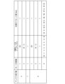
- FIG. 7 is a diagram showing an example of a lookup table in the embodiment.
- the number of antenna elements is "8”
- the number of mode multiplexing is "8”
- the OAM mode index is "[0, 1, -1, 2, -2, 3, -3, 4]".
- the lookup table holds phase offset amounts only for combinations of .
- the algorithm execution unit 133 acquires the number of antenna elements, the number of mode multiplexing, and the OAM mode index from the phase offset holding unit 132, the algorithm execution unit 133 calculates the peak power pair based on the number of antenna elements, the number of mode multiplexing, and the OAM mode index. Derive a phase offset amount that reduces the average power ratio.
- the algorithm execution unit 133 may derive the phase offset amount every time, or the phase offset holding unit 132 may obtain the phase offset amount from the lookup table every time.
- the phase offset notification unit 134 outputs a phase offset amount that reduces the peak power to average power ratio to the phase offset notification device 140 and the phase offset applying device 150 for each OAM mode.
- FIG. 8 is a diagram showing an example of deriving the phase offset amount in the embodiment.
- the phase offset An example of deriving a quantity will be explained.
- the algorithm execution unit 133 derives the phase difference " ⁇ (l)" between adjacent antenna elements when signals corresponding to each OAM mode are multiplexed according to the OAM mode.
- the phase difference " ⁇ (l)" (degrees) is expressed as in equation (1).
- m(l) represents the OAM mode "0, 1, -1,
- l represents the OAM mode index.
- the algorithm execution unit 133 divides the phase difference “ ⁇ (l)” by “90” (degrees) and derives a remainder “ ⁇ mod90 (l)”.
- the remainder " ⁇ mod90 (l)” is expressed as in equation (2).
- the algorithm execution unit 133 classifies the OAM mode "m(l)” in which the remainder " ⁇ mod90 (l)” is "0" into the first group.
- the algorithm execution unit 133 classifies the OAM mode "m(l)” in which the remainder " ⁇ mod90 (l)” is "45” into the second group.
- the number of elements "K" in each group is 4.
- the algorithm execution unit 133 derives the phase offset amount of each OAM mode signal so that the phases of the OAM mode signals in the same group are separated from each other.
- phase offset amounts given to the signals of each OAM mode in the same group may be "0, 22.5, 45, 67.5" in order from the low-order mode, or "0, 22.5" in any order. , 45, 67.5".
- the algorithm execution unit 133 outputs the combination of the number of antenna elements, the number of mode multiplexing, and the index of the OAM mode, and information representing the derived phase offset amount to the phase offset holding unit 132 as a response. Further, the algorithm execution unit 133 outputs information representing the derived phase offset amount to the phase offset notification unit 134.
- FIG. 9 is a diagram showing a first example of offset processing in the embodiment.
- FIG. 9 shows an example of offset processing in a case where the phase offset amount of the offset given to the signal corresponding to each OAM mode is 0 degrees.
- the number of antenna elements (the number of antenna elements) in FIG. 9 is four, as an example.
- the signal 300 is a signal compatible with OAM mode 0.
- Signal 301 is a signal compatible with OAM mode 1.
- Multiplexed signal 400 is a multiplexed OAM mode signal.
- the transmission signal processing device 120 When the transmission signal processing device 120 generates a signal compatible with OAM mode using quadrature amplitude modulation (QAM), the arrangement of signal points of the generated signal is the same for every 90 degrees of phase difference.
- QAM quadrature amplitude modulation
- the signal 300 is supplied to the four antenna elements of the UCA 180 while the phase difference between the antenna elements associated with the signal 300 remains 0 degrees.
- phase differences of 0 degrees, 90 degrees, 180 degrees, and 270 degrees are applied clockwise to the four antenna elements that transmit OAM mode 1 signals.
- the OAM mode generation device 160 combines OAM mode 0 signal points and OAM mode 1 signal points using a discrete Fourier transform matrix 161. This combination doubles the amplitude at the same signal point, thereby increasing the peak power to average power ratio of the wireless signal.
- FIG. 10 is a diagram showing a second example of offset processing in the embodiment. To simplify the explanation, the number of antenna elements in FIG. 10 is four, as an example.
- the signal 300 is output to the four antenna elements of the UCA 180 while the phase difference between the antenna elements associated with the signal 300 remains 0 degrees.
- an offset of 45 degrees of phase offset with respect to the OAM mode 0 signal is applied to the OAM mode 1 signal.
- the arrangement of signal points in OAM mode 0 and the arrangement of signal points in OAM mode 1 are not the same.
- phase differences of 0 degrees, 90 degrees, 180 degrees, and 270 degrees are applied clockwise to the four antenna elements that transmit OAM mode 1 signals.
- the OAM mode generation device 160 combines the signal points of OAM mode 0 and the signal points of OAM mode 1 using the discrete Fourier transform matrix 161 while maintaining a phase offset amount (phase difference) of 45 degrees. This combination reduces the peak power to average power ratio of the wireless signal since the amplitude is not doubled at the same signal point.
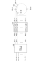
- FIG. 11 is a diagram showing an example of the connection between the OAM mode generation device 160, the RF chain 170, and the UCA 180 in the embodiment.
- M antenna elements 181 are arranged in a circle at equal intervals.
- the phase of the signal transmitted from the antenna element 181-1 of the UCA 180 is taken as the reference (phase 0 degree).
- the output ports “#1” to “#M” in the OAM mode generation device 160 are connected to the input ports “#1” to “#M” in the RF chain 170.
- N is 1 as an example.
- the OAM mode generator 160 generates a multiplexed OAM mode signal (multiple OAM signal ) are output from the output ports “#1” to “#M” in the OAM mode generation device 160 to the input ports “#1” to “#M” in the RF chain 170.
- the RF chain 170 amplifies the multiplexed OAM mode signal (multiple OAM signal) output from the OAM mode generation device 160.
- the RF chain 170 outputs the amplified multiplexed signals of each OAM mode to the UCA 180.
- UCA 180 transmits the signal output from RF chain 170 using radio waves.
- FIG. 12 is a diagram illustrating an example of offset removal processing in the embodiment.
- Multiplexed signal 500 is a multiplexed OAM mode signal.
- the signal 600 is, for example, a signal compatible with OAM mode 0 (a signal associated with OAM mode 0).
- the signal 601 is, for example, a signal compatible with OAM mode 1 (a signal associated with OAM mode 1).
- the OAM mode separator 230 separates the phase of each antenna element of the UCA 210 so that the phase of each antenna element of the UCA 180 is in the opposite rotation direction (opposite phase). Establish. In FIG. 12, the OAM mode separation device 230 rotates each antenna element of the UCA 210 so that the rotation direction is opposite to the phase "[0, 90, 180, 270]" of each antenna element illustrated in FIG. The phase is determined as "[0, -90, -180, -270]".
- the OAM mode separation device 230 uses the inverse discrete Fourier transform matrix 231 to separate the signals of each OAM mode from the multiplexed signal 500.
- the OAM mode separation device 230 uses the inverse discrete Fourier transform matrix 231 to generate a signal corresponding to each OAM mode from the signal of each OAM mode.
- OAM mode separation device 230 outputs signal 600 and signal 601 to received signal processing device 250.
- the phase offset acquisition device 240 acquires information representing the amount of phase offset from the phase offset notification device 140.
- the received signal processing device 250 acquires information representing the amount of phase offset from the phase offset acquisition device 240.
- the received signal processing device 250 removes the phase offset amount offset of the signal corresponding to each OAM mode from the signal corresponding to each OAM mode.
- received signal processing device 250 removes the 45 degree offset from the OAM mode 1 compatible signal.
- the received signal processing device 250 generates a signal 601 from which the offset has been removed.
- the received signal processing device 250 uses the phase offset amount acquired from the phase offset notification device 140 to restore the signal point.
- Received signal processing device 250 outputs each OAM mode signal from which the offset has been removed to demodulator 260.
- the demodulator 260 performs predetermined demodulation processing on each OAM mode signal output from the received signal processing device 250.
- FIG. 13 is a flowchart illustrating an example of an operation for deriving a phase offset amount in the embodiment.
- the algorithm execution unit 133 phase offset amount derivation unit
- the algorithm execution unit 133 derives the remainder "mod( ⁇ (l), 90)" (step S102).
- the algorithm execution unit 133 classifies OAM mode signals associated with the same remainder "mod( ⁇ (l), 90)" into the same group (step S103).
- the algorithm execution unit 133 derives the phase offset amount of each OAM mode signal so that the phases of OAM mode signals classified into the same group are separated from each other (step S104).
- FIG. 14 is a flowchart showing an example of the operation of the transmitting device 100 in the embodiment.
- the phase offset deriving device 130 derives a phase offset amount for each OAM mode so that the positions of signal points do not overlap with each other (step S201).
- the phase offset applying device 150 applies an offset amount of phase offset to the signal corresponding to each OAM mode (step S202).
- the OAM mode generation device 160 generates a signal for each OAM mode from a signal corresponding to each OAM mode to which an offset of the phase offset amount is given (step S203).
- the OAM mode generation device 160 multiplexes the generated signals of each OAM mode for each antenna element 181 forming the UCA 180 (step S204).
- the UCA 180 transmits the multiplexed signals of each OAM mode from the plurality of antenna elements 181 (step S205).
- FIG. 15 is a flowchart showing an example of the operation of the receiving device 200 in the embodiment.
- the UCA 210 acquires the multiplexed signals of each OAM mode (step S301).
- the OAM mode separation device 230 separates the signals of each OAM mode from the multiplexed signals of each OAM mode (step S302).
- the OAM mode separation device 230 generates a signal corresponding to each OAM mode from the signal of each OAM mode (step S303).
- the received signal processing device 250 removes the phase offset amount derived for each OAM mode from the signal corresponding to each OAM mode so that the positions of signal points do not overlap with each other (step S304).
- the received signal processing device 250 performs predetermined received signal processing on the signal corresponding to each OAM mode from which the offset has been removed (step S305).
- the phase offset derivation device 130 (phase offset derivation unit) derives the phase offset amount for each OAM mode so that the positions of signal points do not overlap with each other.
- the phase offset applying device 150 applies an offset of a phase offset amount to a signal corresponding to each OAM mode (a signal associated with each OAM mode).
- the OAM mode generation device 160 (mode generation unit) generates a signal for each OAM mode from a signal corresponding to each OAM mode to which an offset of the phase offset amount is given.
- the OAM mode generation device 160 multiplexes the generated signals of each OAM mode for each antenna element 181 forming the UCA 180 (a plurality of antenna elements).
- the UCA 180 (array antenna) transmits multiplexed signals of each OAM mode from a plurality of antenna elements 181.
- the UCA 210 acquires the multiplexed signals of each OAM mode.
- the OAM mode separator 230 separates each OAM mode signal from the multiplexed OAM mode signals.
- the OAM mode separation device 230 generates a signal corresponding to each OAM mode from the signal of each OAM mode.
- the received signal processing device 250 receives the phase offset amount derived for each OAM mode from the signal corresponding to each OAM mode so that the positions of signal points do not overlap with each other.
- the received signal processing device 250 performs predetermined received signal processing on the signal corresponding to each OAM mode from which the offset has been removed.
- the phase offset acquisition device 240 of the receiving device 200 may estimate the phase offset amount based on the communication parameters using a method similar to the method in which the phase offset derivation device 130 derives the phase offset amount based on the communication parameters.
- the receiving device 200 may use the estimated phase offset amount to remove the offset of the phase offset amount from the signal.
- the transmitting device 100 may or may not include the phase offset notification device 140.
- the transmission signal processing device 120 converted the frequency of the analog signal compatible with each OAM mode to the frequency band of the carrier wave of the wireless signal. Furthermore, the phase offset applying device 150 executed offset processing on the analog signals corresponding to each OAM mode.
- the phase offset applying device 150 may perform offset processing on the digital signal corresponding to each OAM mode.
- the OAM mode generation device 160 may generate a digital signal for each OAM mode specified using communication parameters from a digital signal corresponding to each OAM mode to which an offset has been added.
- the RF chain 170 may perform, for example, frequency conversion, amplification processing, and band limiting on the multiplexed digital signal of each OAM mode.
- FIG. 16 is a diagram showing an example of the hardware configuration of the communication device 2 in the embodiment.
- the communication device 2 corresponds to part or all of the transmitting device 100 and the receiving device 200 of the wireless communication system 1.
- the communication device 2 executes software by a processor 21 such as a CPU (Central Processing Unit) executing a program stored in a storage device 23 having a non-volatile recording medium (non-temporary recording medium) and a memory 22. It is realized as.
- the program may be recorded on a computer-readable non-transitory recording medium.
- Computer-readable non-temporary recording media include portable media such as flexible disks, magneto-optical disks, ROM (Read Only Memory), and CD-ROMs (Compact Disc Read Only Memory), and hard disks built into computer systems. It is a non-temporary recording medium such as a storage device such as.
- the communication unit 24 executes predetermined communication processing.
- Some or all of the functional units of the communication device 2 are analog circuits or digital circuits, such as LSI (Large Scale Integrated circuit), ASIC (Application Specific Integrated Circuit), PLD (Programmable Logic Device), or FPGA (Field It may be realized using hardware including an electronic circuit using a programmable gate array or the like.
- LSI Large Scale Integrated circuit
- ASIC Application Specific Integrated Circuit
- PLD Programmable Logic Device
- FPGA Field It may be realized using hardware including an electronic circuit using a programmable gate array or the like.
- the present invention is applicable to wireless communication systems.
- Antenna Element 200... Receiving device, 210... UCA, 220... RF chain, 230... OAM mode separation device, 231... Inverse discrete Fourier transform matrix, 240... Phase offset acquisition device, 250... Received signal processing device, 260... Demodulator, 300...Signal, 301...Signal, 400...Multiple signal, 500...Multiple signal, 600...Signal, 601...Signal
Landscapes
- Engineering & Computer Science (AREA)
- Computer Networks & Wireless Communication (AREA)
- Signal Processing (AREA)
- Variable-Direction Aerials And Aerial Arrays (AREA)
Abstract
送信装置は、信号点の位置が互いに重ならないように、位相オフセット量を軌道角運動量モードごとに導出する位相オフセット導出部と、各軌道角運動量モードに対応付けられた信号に、位相オフセット量のオフセットを与える位相オフセット付与部と、位相オフセット量のオフセットが与えられた各軌道角運動量モードに対応付けられた信号から、各軌道角運動量モードの信号を生成し、生成された各軌道角運動量モードの信号を、複数のアンテナ素子を構成するアンテナ素子ごとに多重するモード生成部と、多重された各軌道角運動量モードの信号を、複数のアンテナ素子から送信するアレーアンテナとを備える。
Description
本発明は、無線通信方法、無線通信システム、送信装置及び受信装置に関する。
近年、軌道角運動量(OAM : Orbital Angular Momentum)モードに応じて空間多重された無線信号の伝送(OAM多重伝送)が、通信容量の向上を目的として検討されている(非特許文献1参照)。OAMを有する電磁波では、電磁波の伝搬軸に沿って等位相面が螺旋状に分布する。以下、軌道角運動量を有する電磁波の等位相面の位相回転数を「OAMモード」という。同一方向に伝搬する電磁波は、OAMモードごとに直交性を有する。このため、送信装置は、各OAMモードの無線信号を空間多重することが可能である。受信装置は、各OAMモードの無線信号に基づいて、異なるデータ系列の変調信号を各OAMモードの無線信号から分離する。
OAM多重伝送では、等間隔円形アレーアンテナ(UCA : Uniform circular array)が、多重された各OAMモードの無線信号(OAMモード信号)を送信する(非特許文献2参照)。多重された各OAMモードの信号の生成には、離散フーリエ変換(DFT : Discrete Fourier transform)行列が用いられる。各OAMモードの信号の分離には、逆離散フーリエ変換(IDF : Inverse DFT)行列が用いられる。
また、MIMO(Multiple Input Multiple Output)方式の無線信号のピーク電力対平均電力比(PAPR : Peak-to-average power ratio)を低減する技術が提案されている(非特許文献3参照)。
J. Wang et. al., "Terabit free-space data transmission employing orbital angular momentum multiplexing," Nature Photonics, vol.6, pp.488-496, July 2012.
Y. Yan, et. al., "High-capacity millimetre-wave communications with orbital angular momentum multiplexing," Nature Communications, vol.5, DOI: 10.1038/ncomms5876, Sept. 2014.
S.H.Han et.al., "An overview of peak-to-average power ratio reduction techniques for multicarrier transmission," IEEE Wireless Communications, vol.12., Issue.2., pp.56-65., Apr. 2005.
OAM多重伝送では、送信装置が、複数のOAMモードの無線信号(変調信号)を空間多重する。ここで、信号のコンステレーション(信号点群)において、異なるOAMモードの信号点の位置が重なった場合、送信される無線信号のピーク電力対平均電力比(PAPR)は高くなる。ピーク電力対平均電力比が高い無線信号から変換された電力信号を送信装置の増幅器が増幅する場合、増幅器に入力される電力信号のバックオフが所定値以上となるように調整される必要がある。バックオフが所定値以上となるように調整されることによって、送信装置の増幅器から出力される電力信号の電力の低下が問題となる。また、送信電力の低下は受信機側の信号対雑音比(SNR : Signal-to-Noise ratio)の低下につながるので、信号品質が劣化する。
また、MIMO方式の無線信号のピーク電力対平均電力比を低減する技術は、OAM多重伝送にも適用可能である。しかしながら、空間的な直交性が維持された上でピーク電力対平均電力比が低減されるためには、反復演算の実行が必要であることから、演算量が膨大となるという問題がある。
上記事情に鑑み、本発明は、演算量が膨大となることを抑制した上で、軌道角運動量モードに応じて空間多重された無線信号のピーク電力対平均電力比を低減することが可能である無線通信方法、無線通信システム、送信装置及び受信装置を提供することを目的としている。
本発明の一態様は、送信装置と受信装置とを有する無線通信システムが実行する無線通信方法であって、前記送信装置は、信号点の位置が互いに重ならないように、位相オフセット量を軌道角運動量モードごとに導出し、各軌道角運動量モードに対応付けられた信号に、前記位相オフセット量のオフセットを与え、前記位相オフセット量のオフセットが与えられた前記各軌道角運動量モードに対応付けられた信号から、前記各軌道角運動量モードの信号を生成し、生成された前記各軌道角運動量モードの信号を、複数のアンテナ素子を構成するアンテナ素子ごとに多重し、多重された前記各軌道角運動量モードの信号を、前記複数のアンテナ素子から送信し、前記受信装置は、多重された前記各軌道角運動量モードの信号を受信し、多重された前記各軌道角運動量モードの信号から、前記各軌道角運動量モードの信号を分離し、前記各軌道角運動量モードに対応付けられた信号を前記各軌道角運動量モードの信号から生成し、信号点の位置が互いに重ならないように軌道角運動量モードごとに導出された位相オフセット量のオフセットを、前記各軌道角運動量モードに対応付けられた信号から除去し、前記オフセットが除去された前記各軌道角運動量モードに対応付けられた信号に対して、所定の受信信号処理を実行する、無線通信方法である。
本発明の一態様は、送信装置と受信装置とを有する無線通信システムであって、前記送信装置は、信号点の位置が互いに重ならないように、位相オフセット量を軌道角運動量モードごとに導出する位相オフセット導出部と、各軌道角運動量モードに対応付けられた信号に、前記位相オフセット量のオフセットを与える位相オフセット付与部と、前記位相オフセット量のオフセットが与えられた前記各軌道角運動量モードに対応付けられた信号から、前記各軌道角運動量モードの信号を生成し、生成された前記各軌道角運動量モードの信号を、複数のアンテナ素子を構成するアンテナ素子ごとに多重するモード生成部と、多重された前記各軌道角運動量モードの信号を、前記複数のアンテナ素子から送信するアレーアンテナとを備え、前記受信装置は、多重された前記各軌道角運動量モードの信号を取得するアレーアンテナと、多重された前記各軌道角運動量モードの信号から、前記各軌道角運動量モードの信号を分離し、前記各軌道角運動量モードに対応付けられた信号を前記各軌道角運動量モードの信号から生成するモード分離部と、信号点の位置が互いに重ならないように軌道角運動量モードごとに導出された位相オフセット量のオフセットを、前記各軌道角運動量モードに対応付けられた信号から除去し、前記オフセットが除去された前記各軌道角運動量モードに対応付けられた信号に対して、所定の受信信号処理を実行する受信信号処理部と無線通信システムである。
本発明の一態様は、信号点の位置が互いに重ならないように、位相オフセット量を軌道角運動量モードごとに導出する位相オフセット導出部と、各軌道角運動量モードに対応付けられた信号に、前記位相オフセット量のオフセットを与える位相オフセット付与部と、前記位相オフセット量のオフセットが与えられた前記各軌道角運動量モードに対応付けられた信号から、前記各軌道角運動量モードの信号を生成し、生成された前記各軌道角運動量モードの信号を、複数のアンテナ素子を構成するアンテナ素子ごとに多重するモード生成部と、多重された前記各軌道角運動量モードの信号を、前記複数のアンテナ素子から送信するアレーアンテナとを備える送信装置である。
本発明の一態様は、多重された各軌道角運動量モードの信号を取得するアレーアンテナと、多重された前記各軌道角運動量モードの信号から、前記各軌道角運動量モードの信号を分離し、前記各軌道角運動量モードに対応付けられた信号を前記各軌道角運動量モードの信号から生成するモード分離部と、信号点の位置が互いに重ならないように軌道角運動量モードごとに導出された位相オフセット量のオフセットを、前記各軌道角運動量モードに対応付けられた信号から除去し、前記オフセットが除去された前記各軌道角運動量モードに対応付けられた信号に対して、所定の受信信号処理を実行する受信信号処理部とを備える受信装置である。
本発明により、演算量が膨大となることを抑制した上で、軌道角運動量モードに応じて空間多重された無線信号のピーク電力対平均電力比を低減することが可能である。
本発明の実施形態について、図面を参照して詳細に説明する。
図1は、実施形態における、無線通信システム1の構成例を示す図である。無線通信システム1は、電磁波のOAMモードに応じて空間多重された無線信号を伝送する通信システムである。無線通信システム1は、送信装置100と、受信装置200とを備える。
図1は、実施形態における、無線通信システム1の構成例を示す図である。無線通信システム1は、電磁波のOAMモードに応じて空間多重された無線信号を伝送する通信システムである。無線通信システム1は、送信装置100と、受信装置200とを備える。
送信装置100は、送信側の無線通信装置である。送信装置100は、移動しない無線通信装置(基地局)でもよいし、移動する無線通信装置(移動通信端末)でもよい。送信装置100は、電磁波のOAMモードに応じて空間多重された無線信号を、送信装置100の等間隔円形アレーアンテナ(UCA)から送信する。また、送信装置100は、各OAMモードの信号の位相オフセット量を、受信装置200に通知する。
受信装置200は、受信側の無線通信装置である。受信装置200は、移動しない無線通信装置でもよいし、移動する無線通信装置でもよい。受信装置200は、送信装置100から送信された無線信号を、受信装置200の等間隔円形アレーアンテナで受信する。受信装置200は、受信された無線信号を電力信号に変換する。受信装置200は、変換された電力信号から、変調信号をOAMモードごとに分離する。受信装置200は、各OAMモードの変調信号から、各OAMモードに対応付けられた変調信号を生成する。
受信装置200は、受信装置200から通知された位相オフセット量に基づいて、各OAMモードに対応付けられた変調信号から、位相オフセット量のオフセットを除去する。受信装置200は、オフセットが除去された各OAMモードの変調信号に対して、復調処理を実行する。
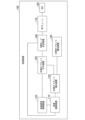
図2は、実施形態における、送信装置100の構成例を示す図である。送信装置100は、送信制御装置110(送信制御部)と、送信信号処理装置120(送信信号処理部)と、位相オフセット導出装置130(位相オフセット導出部)と、位相オフセット通知装置140(位相オフセット通知部)と、位相オフセット付与装置150(位相オフセット付与部)と、OAMモード生成装置160(モード生成部)と、RFチェーン(Radio frequency chain)170(増幅部)と、UCA180(アレーアンテナ)とを備える。
送信制御装置110は、通信パラメータを決定する。通信パラメータは、例えば、モード多重数(多重される信号のOAMモードの個数)と、OAMモードのインデックス(例えば、0,1,-1,2,-2,3,-3,4)と、変調多値数(1シンボル当たりで送信されるビット数)とである。モード多重数の最大値は、アンテナ素子の個数に等しい。送信制御装置110は、送信信号処理装置120と位相オフセット導出装置130とOAMモード生成装置160とに、通信パラメータ(通信パラメータ指定用の信号)を出力する。
送信信号処理装置120には、所定のデータ系列が入力される。送信信号処理装置120は、通信パラメータを送信制御装置110から取得する。送信信号処理装置120は、通信パラメータに基づいて、各OAMモード対応のデジタル信号を生成する。送信信号処理装置120は、各OAMモード対応のデジタル信号を、各OAMモード対応のアナログ信号に変換する。
送信信号処理装置120(コンバータ)は、各OAMモード対応のアナログ信号の周波数を、無線信号の搬送波の周波数帯に変換する。これによって、送信信号処理装置120は、各OAMモード対応の信号(各OAMモードに対応付けられた信号)を生成する。送信信号処理装置120は、各OAMモード対応の信号を、位相オフセット付与装置150に出力する。
位相オフセット導出装置130は、通信パラメータ(通信パラメータ指定用の信号)に基づいて、各OAMモードの信号の位相オフセット量を導出する。位相オフセット導出装置130は、無線信号のピーク電力対平均電力比(PAPR)を低減するように、例えばOAMモード及びモード多重数に基づいて、各OAMモードの信号の位相オフセット量を導出する。
ここで、位相オフセット導出装置130は、UCA180の全てのアンテナ素子から送信される無線信号のピーク電力対平均電力比を低減するように、各OAMモードの信号の位相オフセット量を導出してもよい。位相オフセット導出装置130は、UCA180の特定のアンテナ素子から送信される無線信号のピーク電力対平均電力比を低減するように、各OAMモードの信号の位相オフセット量を導出してもよい。
位相オフセット導出装置130は、各OAMモードの信号の位相オフセット量を表す情報を、位相オフセット通知装置140と位相オフセット付与装置150とに出力する。
位相オフセット通知装置140は、位相オフセット導出装置130から入力された位相オフセット量を表す情報を、所定の通知形式の情報に変換する。位相オフセット通知装置140は、例えばバックボーン回線(不図示)を介して、各OAMモードの信号の位相オフセット量を表す情報を、所定の通知形式で受信装置200に通知する。
位相オフセット付与装置150(オフセット処理装置)は、位相オフセット導出装置130から通知された位相オフセット量のオフセット処理(オフセットの付与)を、各OAMモード対応の信号に対して実行する。位相オフセット付与装置150は、オフセットが付与された各OAMモード対応の信号を、OAMモード生成装置160に出力する。
OAMモード生成装置160は、通信パラメータを送信制御装置110から取得する。OAMモード生成装置160は、オフセットが付与された各OAMモード対応の信号を、位相オフセット付与装置150から取得する。OAMモード生成装置160は、通信パラメータを用いて指定された各OAMモードの信号を、オフセットが付与された各OAMモード対応の信号から生成する。なお、ピーク電力対平均電力比が低減されるのであれば、位相オフセット量は0でもよい。
ここで、OAMモード生成装置160は、各OAMモードの信号に対して離散フーリエ変換行列を用いて、通信パラメータを用いて指定された各OAMモードの信号(OAM信号)を生成する。OAMモード生成装置160は、生成された各OAMモードの信号を、離散フーリエ変換行列を用いて、UCA180のアンテナ素子ごとに多重する。OAMモード生成装置160は、多重された各OAMモードの信号(多重OAM信号)を、RFチェーン170に出力する。
RFチェーン170(RF処理部)は、周波数変換器と、フィルタと、増幅器とを備える。RFチェーン170は、多重された各OAMモードの信号に対して、例えば、周波数変換、帯域制限及び増幅処理を実行する。RFチェーン170は、増幅処理後の多重された各OAMモードの信号(電力信号)を、UCA180に出力する。
UCA180は、等間隔円形アレーアンテナである。等間隔円形アレーアンテナでは、複数(M個)のアンテナ素子が、等間隔で円状に配置されている。UCA180は、増幅処理の実行後の多重された各OAMモードの信号に基づいて、電磁波のOAMモードに応じて空間多重された無線信号を送信する。
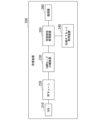
図3は、実施形態における、受信装置200の構成例を示す図である。受信装置200は、UCA210(アレーアンテナ)と、RFチェーン220(増幅部)と、OAMモード分離装置230(モード分離部)と、位相オフセット取得装置240(位相オフセット取得部)と、受信信号処理装置250と、復調器260とを備える。
UCA210は、等間隔円形アレーアンテナである。等間隔円形アレーアンテナでは、複数(M個)のアンテナ素子が、等間隔で円状に配置されている。UCA210は、電磁波のOAMモードに応じて空間多重された無線信号を、UCA180から受信(取得)する。UCA210は、受信された無線信号に応じた多重された各OAMモードの信号(電力信号)を、RFチェーン220に出力する。
RFチェーン220(RF処理部)は、多重された各OAMモードの信号に対して、例えば、増幅処理及び帯域制限を実行する。RFチェーン220は、多重された各OAMモードの信号に対して、周波数変換処理を実行してもよい。RFチェーン220は、増幅処理後の多重された各OAMモードの信号(電力信号)を、OAMモード分離装置230に出力する。
OAMモード分離装置230は、多重された各OAMモードの信号に対して逆離散フーリエ変換行列を用いて、多重された各OAMモードの信号から、各OAMモードの信号を分離する。OAMモード分離装置230は、逆離散フーリエ変換行列を用いて、各OAMモード対応の信号を各OAMモードの信号から生成する。OAMモード分離装置230は、各OAMモード対応の信号を、受信信号処理装置250に出力する。
位相オフセット取得装置240は、所定の通知形式で位相オフセット通知装置140から通知された位相オフセット量を表す情報を、受信信号処理装置250に出力する。
受信信号処理装置250は、所定の受信信号処理を実行する装置である。受信信号処理装置250は、位相オフセット量を表す情報を、位相オフセット取得装置240から取得する。受信信号処理装置250は、通知された位相オフセット量に基づいて、各OAMモード対応の信号から、位相オフセット量のオフセットをOAMモードごとに除去する。受信信号処理装置250は、オフセットが除去された各OAMモード対応の信号に対して、所定の受信信号処理を実行する。これによって、受信信号処理装置250は、各OAMモード対応の変調信号を生成する。受信信号処理装置250は、各OAMモード対応の変調信号を、復調器260に出力する。復調器260は、各OAMモード対応の変調信号に対して、所定の復調処理を実行する。
次に、OAMモードの詳細について説明する。
図4は、実施形態における、OAMモードの例を示す図である。OAMモード生成装置160は、RFチェーン170を介してUCA180の各アンテナ素子に入力される電力信号に、離散フーリエ変換行列を用いて位相差を与える。これによって、OAMモード生成装置160は、多重された各OAMモードの信号を生成する。
図4は、実施形態における、OAMモードの例を示す図である。OAMモード生成装置160は、RFチェーン170を介してUCA180の各アンテナ素子に入力される電力信号に、離散フーリエ変換行列を用いて位相差を与える。これによって、OAMモード生成装置160は、多重された各OAMモードの信号を生成する。
OAMモード生成装置160は、OAMモード「n」の信号の位相が「n」回転するように、UCA180の各アンテナ素子に入力される信号に、隣接するアンテナ素子の間の位相差を与えることによって、OAMモード「n」の信号を生成する。
例えば、UCA180の8個のアンテナ素子に供給されるOAMモード2の信号が生成される場合、OAMモード生成装置160は、OAMモード2の信号の位相が2回転するように、0度と90度と180度と270度と、0度と90度と180度と270度との各位相差を、時計回りの順でアンテナ素子に与える。
次に、送信装置100の詳細について説明する。
図5は、実施形態における、送信制御装置110の構成例を示す図である。送信制御装置110は、特性情報取得部111と、送信OAMモード決定部112と、多重数決定部113と、送信信号パラメータ決定部114とを備える。
図5は、実施形態における、送信制御装置110の構成例を示す図である。送信制御装置110は、特性情報取得部111と、送信OAMモード決定部112と、多重数決定部113と、送信信号パラメータ決定部114とを備える。
特性情報取得部111は、通信特性情報を取得する装置である。通信特性情報は、送信装置100と受信装置200との間の通信の特性を表す情報である。通信特性情報が表す特性は、例えば、送信装置100と受信装置200との間の距離(以下「送受信間距離」という。)と、受信信号電力対干渉雑音電力比(SINR : Signal-to-interference and noise ratio)と、OAMモードの信号間の干渉の特性とである。
送信OAMモード決定部112は、例えば送受信間距離及び受信信号電力対干渉雑音電力比に基づいて、送信される信号のOAMモード(以下「送信OAMモード」という。)を決定する。多重数決定部113は、例えば送受信間距離及び受信信号電力対干渉雑音電力比に基づいて、モード多重数を決定する。
送信信号パラメータ決定部114は、例えば送受信間距離及び受信信号電力対干渉雑音電力比に基づいて、変調多値数及び符号化率等の送信信号パラメータを決定する。送信制御装置110における、送信OAMモードの決定と、モード多重数の決定と、送信信号パラメータの決定との順番は、任意である。
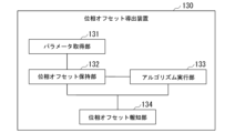
図6は、実施形態における、位相オフセット導出装置130の構成例を示す図である。位相オフセット導出装置130は、パラメータ取得部131と、位相オフセット保持部132と、アルゴリズム実行部133と、位相オフセット報知部134とを備える。
パラメータ取得部131は、アンテナ素子数と、モード多重数と、OAMモードのインデックスとを、通信パラメータとして送信制御装置110から取得する。パラメータ取得部131は、アンテナ素子数と、モード多重数と、OAMモードのインデックスとを、通信パラメータとして位相オフセット保持部132に出力する。
位相オフセット保持部132は、ルックアップテーブル(LUT: Lookup table)を予め保持する。位相オフセット保持部132は、ピーク電力対平均電力比を低減する位相オフセット量を、アンテナ素子数とモード多重数とOAMモードのインデックスに基づいて、ルックアップテーブルから取得する。例えば、位相オフセット保持部132は、ピーク電力対平均電力比を最小にするための位相オフセット量を、OAMモードごとにルックアップテーブルから取得する。OAMモードごとに取得された位相オフセット量は、各OAMモード対応の信号に与えられる。位相オフセット保持部132は、ルックアップテーブルから取得された位相オフセット量を表す情報を、位相オフセット報知部134に出力する。
パラメータ取得部131によって取得された通信パラメータに対応する位相オフセット量の情報をルックアップテーブルが保持していない場合、位相オフセット保持部132は、アンテナ素子数とモード多重数とOAMモードのインデックスとを、アルゴリズム実行部133に出力する。位相オフセット保持部132は、ピーク電力対平均電力比を低減する位相オフセット量を表す情報と、アンテナ素子数と、モード多重数と、OAMモードのインデックスとを、応答として、アルゴリズム実行部133から取得する。位相オフセット保持部132は、ピーク電力対平均電力比を低減する位相オフセット量を表す情報を、アンテナ素子数とモード多重数とOAMモードのインデックスとの組み合わせに対応付けて、ルックアップテーブルに登録する。これによって、ルックアップテーブルが更新される。
図7は、実施形態における、ルックアップテーブルの例を示す図である。図7では、一例として、アンテナ素子数「8」と、モード多重数「8」と、OAMモードのインデックス「[0,1,-1,2,-2,3,-3,4]」との組み合わせについてのみ、ルックアップテーブルは、位相オフセット量を保持している。
図6に戻り、位相オフセット導出装置130の構成例の説明を続ける。アルゴリズム実行部133は、アンテナ素子数とモード多重数とOAMモードのインデックスとを位相オフセット保持部132から取得した場合、アンテナ素子数とモード多重数とOAMモードのインデックスとに基づいて、ピーク電力対平均電力比を低減する位相オフセット量を導出する。
なお、アルゴリズム実行部133は位相オフセット量を毎回導出してもよいし、位相オフセット保持部132が位相オフセット量をルックアップテーブルから毎回取得してもよい。
位相オフセット報知部134は、ピーク電力対平均電力比を低減する位相オフセット量を、OAMモードごとに位相オフセット通知装置140及び位相オフセット付与装置150に出力する。
次に、位相オフセット量の導出例について説明する。
図8は、実施形態における、位相オフセット量の導出例を示す図である。一例として、アンテナ素子数「8」と、モード多重数「8」と、OAMモードのインデックス「[0,1,-1,2,-2,3,-3,4]」とについて、位相オフセット量の導出例を説明する。
図8は、実施形態における、位相オフセット量の導出例を示す図である。一例として、アンテナ素子数「8」と、モード多重数「8」と、OAMモードのインデックス「[0,1,-1,2,-2,3,-3,4]」とについて、位相オフセット量の導出例を説明する。
アルゴリズム実行部133は、各OAMモード対応の信号がOAMモードに応じて多重された場合における、隣接するアンテナ素子間の位相差「Δφ(l)」を導出する。位相差「Δφ(l)」(度)は、式(1)のように表される。
Δφ(l)=|m(l)/M×360| …(1)
ここで、「m(l)」は、OAMモード「0,1,-1,…」を表す。「l」は、OAMモードのインデックスを表す。図8では、各OAMモードのアンテナ素子間の位相差は、「Δφ(l)=[0,45,45,90,90,135,135,180]」である。
アルゴリズム実行部133は、位相差「Δφ(l)」を「90」(度)で除算し、剰余「Δφmod90(l)」を導出する。剰余「Δφmod90(l)」は、式(2)のように表される。
Δφmod90(l)=mod(Δφ(l),90) …(2)
ここで、剰余は、「Δφmod90(l)=[0,45,45,0,0,45,45,0])となる。このように、剰余「Δφmod90(l)」は、「0」又は「45」になる。
アルゴリズム実行部133は、剰余「Δφmod90(l)」が「0」になるOAMモード「m(l)」を、第1グループに分類する。アルゴリズム実行部133は、剰余「Δφmod90(l)」が「45」になるOAMモード「m(l)」を、第2グループに分類する。
第1グループのOAMモード:
m(l)∈(Δφmod90(l)=0)=[0,2,-2,4]
m(l)∈(Δφmod90(l)=0)=[0,2,-2,4]
第2グループのOAMモード:
m(l)∈(Δφmod90(l)=45)=[1,-1,3,-3]
m(l)∈(Δφmod90(l)=45)=[1,-1,3,-3]
各グループの要素数「K」は、4である。アルゴリズム実行部133は、同一グループにおいてOAMモードの信号の位相が互いに離れるように、各OAMモードの信号の位相オフセット量を導出する。図8では、OAMモード「[0,2,-2,4]」の信号の位相が互いに離れるように、第1グループの各OAMモードの信号の位相オフセット量「22.5度(=90度/K)」を導出する。また、OAMモード「[1,-1,3,-3]」の信号の位相が互いに離れるように、第2グループの各OAMモードの信号の位相オフセット量「22.5度(=90度/K)」を導出する。
ここで、同一グループにおいて各OAMモードの信号に与えられる位相オフセット量は、低次モードから順に「0,22.5,45,67.5」でもよいし、任意の順に「0,22.5,45,67.5」でもよい。
アルゴリズム実行部133は、アンテナ素子数とモード多重数とOAMモードのインデックスとの組み合わせと、導出された位相オフセット量を表す情報とを、応答として、位相オフセット保持部132に出力する。また、アルゴリズム実行部133は、導出された位相オフセット量を表す情報を、位相オフセット報知部134に出力する。
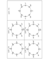
図9は、実施形態における、オフセット処理の第1例を示す図である。図9は、図10に対する比較例として、各OAMモード対応の信号に付与されたオフセットの位相オフセット量が仮に0度である場合について、オフセット処理の例を示す。説明を簡単にするため、図9におけるアンテナ素子の個数(アンテナ素子数)は、一例として4個である。
信号300は、OAMモード0対応の信号である。信号301は、OAMモード1対応の信号である。多重信号400は、多重されたOAMモードの信号である。直交振幅変調(QAM : Quadrature amplitude modulation)を用いて送信信号処理装置120がOAMモード対応の信号を生成した場合、生成された信号の信号点の配置は、位相差90度ごとに同一である。
信号300に対応付けられたアンテナ素子間の位相差が0度のまま、信号300は、UCA180の4個のアンテナ素子に供給される。これに対して、OAMモード1の信号を送信する4個のアンテナ素子には、0度と90度と180度と270度との各位相差が、時計回りに付与される。
このように各位相差が信号に付与された場合でも、OAMモード0の信号点の配置と、OAMモード1の信号点の配置とは、同一である。OAMモード生成装置160は、OAMモード0の信号点とOAMモード1の信号点を、離散フーリエ変換行列161を用いて合成する。この合成によって、同一の信号点において振幅が2倍になるので、無線信号のピーク電力対平均電力比は大きくなる。
図10は、実施形態における、オフセット処理の第2例を示す図である。説明を簡単にするため、図10におけるアンテナ素子の個数は、一例として4個である。
信号300に対応付けられたアンテナ素子間の位相差が0度のまま、信号300は、UCA180の4個のアンテナ素子に出力される。これに対して、OAMモード0の信号に対して45度の位相オフセット量のオフセットが、OAMモード1の信号に付与される。これによって、OAMモード0の信号点の配置と、OAMモード1の信号点の配置とは、同一にならない。
更に、OAMモード1の信号を送信する4個のアンテナ素子には、0度と90度と180度と270度との各位相差が、時計回りに付与される。OAMモード生成装置160は、45度の位相オフセット量(位相差)を保ったまま、OAMモード0の信号点とOAMモード1の信号点を、離散フーリエ変換行列161を用いて合成する。この合成によって、同一の信号点において振幅が2倍にならないので、無線信号のピーク電力対平均電力比は低減される。
図11は、実施形態における、OAMモード生成装置160とRFチェーン170とUCA180との接続例を示す図である。UCA180では、M個のアンテナ素子181が等間隔で円状に配置されている。図11では、一例として、UCA180のアンテナ素子181-1から送信される信号の位相を基準(位相0度)とする。OAMモード生成装置160における「#1」から「#M」までの出力ポートは、RFチェーン170における「#1」から「#M」までの入力ポートに接続されている。
OAMモードn(n=0からNまでの整数)対応の信号が、OAMモード生成装置160に位相オフセット付与装置150から入力される。図11では、「N」は、一例として1である。OAMモード生成装置160は、基準位相に対する位相差「x」を持ったOAMモード0の信号と、基準位相に対する位相差「y」を持ったOAMモード1の信号との合波結果(多重OAM信号)を、OAMモード生成装置160における「#1」から「#M」までの出力ポートから、RFチェーン170における「#1」から「#M」までの入力ポートに出力する。
ここで、OAMモード生成装置160における出力ポート「#m」は、基準位相に対する位相差「x=((m-1)/M×360×0)」度のOAMモード0の信号と、基準位相に対する位相差「y=((m-1)/M×360×1)」度のOAMモード1の信号とを、RFチェーン170を介して、アンテナ素子「#m」に出力する。
RFチェーン170は、OAMモード生成装置160から出力された多重されたOAMモードの信号(多重OAM信号)を増幅する。RFチェーン170は、増幅後の多重された各OAMモードの信号を、UCA180に出力する。UCA180は、RFチェーン170から出力された信号を、電波を用いて送信する。
次に、受信装置200の詳細について説明する。
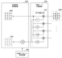
図12は、実施形態における、オフセット除去処理の例を示す図である。多重信号500は、多重されたOAMモードの信号である。信号600は、一例として、OAMモード0対応の信号(OAMモード0に対応付けられた信号)である。信号601は、一例として、OAMモード1対応の信号(OAMモード1に対応付けられた信号)である。
図12は、実施形態における、オフセット除去処理の例を示す図である。多重信号500は、多重されたOAMモードの信号である。信号600は、一例として、OAMモード0対応の信号(OAMモード0に対応付けられた信号)である。信号601は、一例として、OAMモード1対応の信号(OAMモード1に対応付けられた信号)である。
多重信号500(多重OAM信号)を分離する目的で、OAMモード分離装置230は、UCA180の各アンテナ素子の位相に対して逆回転方向(逆位相)となるように、UCA210の各アンテナ素子の位相を定める。図12では、図10に例示された各アンテナ素子の位相「[0,90,180,270]」に対して逆回転方向となるように、OAMモード分離装置230は、UCA210の各アンテナ素子の位相を、「[0,-90,-180,-270]」と定める。
OAMモード分離装置230は、逆離散フーリエ変換行列231を用いて、各OAMモードの信号を多重信号500から分離する。OAMモード分離装置230は、逆離散フーリエ変換行列231を用いて、各OAMモード対応の信号を各OAMモードの信号から生成する。図12では、OAMモード分離装置230は、信号600及び信号601を、受信信号処理装置250に出力する。
位相オフセット取得装置240は、位相オフセット量を表す情報を、位相オフセット通知装置140から取得する。受信信号処理装置250は、位相オフセット量を表す情報を、位相オフセット取得装置240から取得する。
受信信号処理装置250は、各OAMモード対応の信号の位相オフセット量のオフセットを、各OAMモード対応の信号から除去する。図12では、受信信号処理装置250は、45度のオフセットを、OAMモード1対応の信号から除去する。これによって、受信信号処理装置250は、オフセットが除去された信号601を生成する。このように、受信信号処理装置250は、位相オフセット通知装置140から取得された位相オフセット量を用いて、信号点を復元する。受信信号処理装置250は、オフセットが除去された各OAMモードの信号を、復調器260に出力する。復調器260は、受信信号処理装置250から出力された各OAMモードの信号に対して、所定の復調処理を実行する。
次に、無線通信システム1の動作例を説明する。
図13は、実施形態における、位相オフセット量の導出動作の例を示すフローチャートである。アルゴリズム実行部133(位相オフセット量導出部)は、アンテナ素子間の位相差「Δφ(l)」を、OAMモードごとに導出する(ステップS101)。アルゴリズム実行部133は、剰余「mod(Δφ(l),90)」を導出する(ステップS102)。
図13は、実施形態における、位相オフセット量の導出動作の例を示すフローチャートである。アルゴリズム実行部133(位相オフセット量導出部)は、アンテナ素子間の位相差「Δφ(l)」を、OAMモードごとに導出する(ステップS101)。アルゴリズム実行部133は、剰余「mod(Δφ(l),90)」を導出する(ステップS102)。
アルゴリズム実行部133は、同じ剰余「mod(Δφ(l),90)」に対応付けられたOAMモード信号を、同じグループに分類する(ステップS103)。アルゴリズム実行部133は、同じグループに分類されたOAMモードの信号の位相が互いに離れるように、各OAMモード信号の位相オフセット量を導出する(ステップS104)。
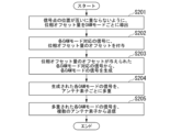
図14は、実施形態における、送信装置100の動作例を示すフローチャートである。位相オフセット導出装置130は、信号点の位置が互いに重ならないように、位相オフセット量をOAMモードごとに導出する(ステップS201)。位相オフセット付与装置150は、各OAMモード対応の信号に、位相オフセット量のオフセットを与える(ステップS202)。
OAMモード生成装置160は、位相オフセット量のオフセットが与えられた各OAMモード対応の信号から、各OAMモードの信号を生成する(ステップS203)。OAMモード生成装置160は、生成された各OAMモードの信号を、UCA180を構成するアンテナ素子181ごとに多重する(ステップS204)。UCA180は、多重された各OAMモードの信号を、複数のアンテナ素子181から送信する(ステップS205)。
図15は、実施形態における、受信装置200の動作例を示すフローチャートである。UCA210は、多重された各OAMモードの信号を取得する(ステップS301)。OAMモード分離装置230は、多重された各OAMモードの信号から、各OAMモードの信号を分離する(ステップS302)。OAMモード分離装置230は、各OAMモード対応の信号を、各OAMモードの信号から生成する(ステップS303)。
受信信号処理装置250は、信号点の位置が互いに重ならないようにOAMモードごとに導出された位相オフセット量のオフセットを、各OAMモード対応の信号から除去する(ステップS304)。受信信号処理装置250は、オフセットが除去された各OAMモード対応の信号に対して、所定の受信信号処理を実行する(ステップS305)。
以上のように、送信装置100において、位相オフセット導出装置130(位相オフセット導出部)は、信号点の位置が互いに重ならないように、位相オフセット量をOAMモードごとに導出する。位相オフセット付与装置150(位相オフセット付与部)は、各OAMモード対応の信号(各OAMモードに対応付けられた信号)に、位相オフセット量のオフセットを与える。OAMモード生成装置160(モード生成部)は、位相オフセット量のオフセットが与えられた各OAMモード対応の信号から、各OAMモードの信号を生成する。OAMモード生成装置160は、生成された各OAMモードの信号を、UCA180(複数のアンテナ素子)を構成するアンテナ素子181ごとに多重する。UCA180(アレーアンテナ)は、多重された各OAMモードの信号を、複数のアンテナ素子181から送信する。
受信装置200において、UCA210(アレーアンテナ)は、多重された各OAMモードの信号を取得する。OAMモード分離装置230(モード分離部)は、多重された各OAMモードの信号から、各OAMモードの信号を分離する。OAMモード分離装置230は、各OAMモード対応の信号を、各OAMモードの信号から生成する。受信信号処理装置250(受信信号処理部)は、信号点の位置が互いに重ならないようにOAMモードごとに導出された位相オフセット量のオフセットを、各OAMモード対応の信号から除去する。受信信号処理装置250は、オフセットが除去された各OAMモード対応の信号に対して、所定の受信信号処理を実行する。
これらのように、OAM多重伝送の無線通信におけるプリコーダの特徴が着目されることによって同相合成が回避され、演算量が膨大となることを抑制した上で、軌道角運動量モードに応じて空間多重された無線信号のピーク電力対平均電力比を低減することが可能である。また、通信品質が向上する。
(第1変形例)
受信装置200の位相オフセット取得装置240は、位相オフセット導出装置130が通信パラメータに基づいて位相オフセット量を導出した方法と同様の方法で、通信パラメータに基づいて位相オフセット量を推定してもよい。受信装置200は、推定された位相オフセット量を用いて、位相オフセット量のオフセットを信号から除去してもよい。この場合、送信装置100は、位相オフセット通知装置140を備えてよいし、備えなくてもよい。
受信装置200の位相オフセット取得装置240は、位相オフセット導出装置130が通信パラメータに基づいて位相オフセット量を導出した方法と同様の方法で、通信パラメータに基づいて位相オフセット量を推定してもよい。受信装置200は、推定された位相オフセット量を用いて、位相オフセット量のオフセットを信号から除去してもよい。この場合、送信装置100は、位相オフセット通知装置140を備えてよいし、備えなくてもよい。
(第2変形例)
上記の実施形態では、送信信号処理装置120が、各OAMモード対応のアナログ信号の周波数を、無線信号の搬送波の周波数帯に変換した。また、位相オフセット付与装置150は、各OAMモード対応のアナログ信号に対して、オフセット処理を実行した。
上記の実施形態では、送信信号処理装置120が、各OAMモード対応のアナログ信号の周波数を、無線信号の搬送波の周波数帯に変換した。また、位相オフセット付与装置150は、各OAMモード対応のアナログ信号に対して、オフセット処理を実行した。
実施形態の第2変形例では、位相オフセット付与装置150は、各OAMモード対応のデジタル信号に対して、オフセット処理を実行してもよい。OAMモード生成装置160は、通信パラメータを用いて指定された各OAMモードのデジタル信号を、オフセットが付与された各OAMモード対応のデジタル信号から生成してもよい。RFチェーン170は、多重された各OAMモードのデジタル信号に対して、例えば、周波数変換、増幅処理及び帯域制限を実行してもよい。
(ハードウェア構成例)
図16は、実施形態における、通信装置2のハードウェア構成例を示す図である。通信装置2は、無線通信システム1の送信装置100及び受信装置200のうちの一部又は全部に相当する。
図16は、実施形態における、通信装置2のハードウェア構成例を示す図である。通信装置2は、無線通信システム1の送信装置100及び受信装置200のうちの一部又は全部に相当する。
通信装置2は、CPU(Central Processing Unit)等のプロセッサ21が、不揮発性の記録媒体(非一時的記録媒体)を有する記憶装置23とメモリ22とに記憶されたプログラムを実行することにより、ソフトウェアとして実現される。プログラムは、コンピュータ読み取り可能な非一時的記録媒体に記録されてもよい。コンピュータ読み取り可能な非一時的記録媒体とは、例えばフレキシブルディスク、光磁気ディスク、ROM(Read Only Memory)、CD-ROM(Compact Disc Read Only Memory)等の可搬媒体、コンピュータシステムに内蔵されるハードディスク等の記憶装置などの非一時的記録媒体である。通信部24は、所定の通信処理を実行する。
通信装置2の各機能部の一部又は全部は、アナログ回路又はデジタル回路であり、例えば、LSI(Large Scale Integrated circuit)、ASIC(Application Specific Integrated Circuit)、PLD(Programmable Logic Device)又はFPGA(Field Programmable Gate Array)等を用いた電子回路(electronic circuit又はcircuitry)を含むハードウェアを用いて実現されてもよい。
以上、この発明の実施形態について図面を参照して詳述してきたが、具体的な構成はこの実施形態に限られるものではなく、この発明の要旨を逸脱しない範囲の設計等も含まれる。
本発明は、無線通信システムに適用可能である。
1…無線通信システム、2…通信装置、21…プロセッサ、22…メモリ、23…記憶装置、24…通信部、100…送信装置、110…送信制御装置、111…特性情報取得部、112…送信OAMモード決定部、113…多重数決定部、114…送信信号パラメータ決定部、120…送信信号処理装置、130…位相オフセット導出装置、131…パラメータ取得部、132…位相オフセット保持部、133…アルゴリズム実行部、134…位相オフセット報知部、140…位相オフセット通知装置、150…位相オフセット付与装置、160…OAMモード生成装置、161…離散フーリエ変換行列、170…RFチェーン、180…UCA、181…アンテナ素子、200…受信装置、210…UCA、220…RFチェーン、230…OAMモード分離装置、231…逆離散フーリエ変換行列、240…位相オフセット取得装置、250…受信信号処理装置、260…復調器、300…信号、301…信号、400…多重信号、500…多重信号、600…信号、601…信号
Claims (6)
- 送信装置と受信装置とを有する無線通信システムが実行する無線通信方法であって、
前記送信装置は、
信号点の位置が互いに重ならないように、位相オフセット量を軌道角運動量モードごとに導出し、
各軌道角運動量モードに対応付けられた信号に、前記位相オフセット量のオフセットを与え、
前記位相オフセット量のオフセットが与えられた前記各軌道角運動量モードに対応付けられた信号から、前記各軌道角運動量モードの信号を生成し、生成された前記各軌道角運動量モードの信号を、複数のアンテナ素子を構成するアンテナ素子ごとに多重し、
多重された前記各軌道角運動量モードの信号を、前記複数のアンテナ素子から送信し、
前記受信装置は、
多重された前記各軌道角運動量モードの信号を受信し、
多重された前記各軌道角運動量モードの信号から、前記各軌道角運動量モードの信号を分離し、前記各軌道角運動量モードに対応付けられた信号を前記各軌道角運動量モードの信号から生成し、
信号点の位置が互いに重ならないように軌道角運動量モードごとに導出された位相オフセット量のオフセットを、前記各軌道角運動量モードに対応付けられた信号から除去し、前記オフセットが除去された前記各軌道角運動量モードに対応付けられた信号に対して、所定の受信信号処理を実行する、
無線通信方法。 - 送信装置と受信装置とを有する無線通信システムであって、
前記送信装置は、
信号点の位置が互いに重ならないように、位相オフセット量を軌道角運動量モードごとに導出する位相オフセット導出部と、
各軌道角運動量モードに対応付けられた信号に、前記位相オフセット量のオフセットを与える位相オフセット付与部と、
前記位相オフセット量のオフセットが与えられた前記各軌道角運動量モードに対応付けられた信号から、前記各軌道角運動量モードの信号を生成し、生成された前記各軌道角運動量モードの信号を、複数のアンテナ素子を構成するアンテナ素子ごとに多重するモード生成部と、
多重された前記各軌道角運動量モードの信号を、前記複数のアンテナ素子から送信するアレーアンテナとを備え、
前記受信装置は、
多重された前記各軌道角運動量モードの信号を取得するアレーアンテナと、
多重された前記各軌道角運動量モードの信号から、前記各軌道角運動量モードの信号を分離し、前記各軌道角運動量モードに対応付けられた信号を前記各軌道角運動量モードの信号から生成するモード分離部と、
信号点の位置が互いに重ならないように軌道角運動量モードごとに導出された位相オフセット量のオフセットを、前記各軌道角運動量モードに対応付けられた信号から除去し、前記オフセットが除去された前記各軌道角運動量モードに対応付けられた信号に対して、所定の受信信号処理を実行する受信信号処理部と
無線通信システム。 - 信号点の位置が互いに重ならないように、位相オフセット量を軌道角運動量モードごとに導出する位相オフセット導出部と、
各軌道角運動量モードに対応付けられた信号に、前記位相オフセット量のオフセットを与える位相オフセット付与部と、
前記位相オフセット量のオフセットが与えられた前記各軌道角運動量モードに対応付けられた信号から、前記各軌道角運動量モードの信号を生成し、生成された前記各軌道角運動量モードの信号を、複数のアンテナ素子を構成するアンテナ素子ごとに多重するモード生成部と、
多重された前記各軌道角運動量モードの信号を、前記複数のアンテナ素子から送信するアレーアンテナと
を備える送信装置。 - 前記位相オフセット量を受信装置に通知する位相オフセット通知部を更に備える、請求項3に記載の送信装置。
- 多重された各軌道角運動量モードの信号を取得するアレーアンテナと、
多重された前記各軌道角運動量モードの信号から、前記各軌道角運動量モードの信号を分離し、前記各軌道角運動量モードに対応付けられた信号を前記各軌道角運動量モードの信号から生成するモード分離部と、
信号点の位置が互いに重ならないように軌道角運動量モードごとに導出された位相オフセット量のオフセットを、前記各軌道角運動量モードに対応付けられた信号から除去し、前記オフセットが除去された前記各軌道角運動量モードに対応付けられた信号に対して、所定の受信信号処理を実行する受信信号処理部と
を備える受信装置。 - 前記位相オフセット量を送信装置から取得する、又は、前記位相オフセット量を推定する位相オフセット取得部を更に備える、請求項5に記載の受信装置。
Priority Applications (2)
| Application Number | Priority Date | Filing Date | Title |
|---|---|---|---|
| PCT/JP2022/017774 WO2023199461A1 (ja) | 2022-04-14 | 2022-04-14 | 無線通信方法、無線通信システム、送信装置及び受信装置 |
| JP2024515260A JP7748008B2 (ja) | 2022-04-14 | 2022-04-14 | 無線通信方法、無線通信システム、送信装置及び受信装置 |
Applications Claiming Priority (1)
| Application Number | Priority Date | Filing Date | Title |
|---|---|---|---|
| PCT/JP2022/017774 WO2023199461A1 (ja) | 2022-04-14 | 2022-04-14 | 無線通信方法、無線通信システム、送信装置及び受信装置 |
Publications (1)
| Publication Number | Publication Date |
|---|---|
| WO2023199461A1 true WO2023199461A1 (ja) | 2023-10-19 |
Family
ID=88329353
Family Applications (1)
| Application Number | Title | Priority Date | Filing Date |
|---|---|---|---|
| PCT/JP2022/017774 Ceased WO2023199461A1 (ja) | 2022-04-14 | 2022-04-14 | 無線通信方法、無線通信システム、送信装置及び受信装置 |
Country Status (2)
| Country | Link |
|---|---|
| JP (1) | JP7748008B2 (ja) |
| WO (1) | WO2023199461A1 (ja) |
Citations (1)
| Publication number | Priority date | Publication date | Assignee | Title |
|---|---|---|---|---|
| WO2019116774A1 (ja) * | 2017-12-14 | 2019-06-20 | 日本電気株式会社 | 無線送信装置、ベースバンド処理装置、無線送信方法、及び無線受信装置 |
-
2022
- 2022-04-14 JP JP2024515260A patent/JP7748008B2/ja active Active
- 2022-04-14 WO PCT/JP2022/017774 patent/WO2023199461A1/ja not_active Ceased
Patent Citations (1)
| Publication number | Priority date | Publication date | Assignee | Title |
|---|---|---|---|---|
| WO2019116774A1 (ja) * | 2017-12-14 | 2019-06-20 | 日本電気株式会社 | 無線送信装置、ベースバンド処理装置、無線送信方法、及び無線受信装置 |
Non-Patent Citations (2)
| Title |
|---|
| CHEN RUI; ZHOU HONG; LI JIANDONG: "Constant Envelope Multi-Mode OAM Communication System with UCA Antennas", 2019 IEEE GLOBAL COMMUNICATIONS CONFERENCE (GLOBECOM), IEEE, 9 December 2019 (2019-12-09), pages 1 - 5, XP033722225, DOI: 10.1109/GLOBECOM38437.2019.9013387 * |
| WU QIULI, JIANG JIN, ZHANG CHAO: "Orbital Angular Momentum Spread Transmission With Interferometry Codes for Peak-to-Average Power Ratio Reduction", IEEE ANTENNAS AND WIRELESS PROPAGATION LETTERS, IEEE, PISCATAWAY, NJ, US, vol. 21, no. 3, 1 March 2022 (2022-03-01), US , pages 436 - 440, XP093099982, ISSN: 1536-1225, DOI: 10.1109/LAWP.2021.3131767 * |
Also Published As
| Publication number | Publication date |
|---|---|
| JP7748008B2 (ja) | 2025-10-02 |
| JPWO2023199461A1 (ja) | 2023-10-19 |
Similar Documents
| Publication | Publication Date | Title |
|---|---|---|
| KR101245682B1 (ko) | Sc-fdma 시스템들에서 papr 감소를 위한 방법들 및 시스템 | |
| CN101729483A (zh) | 无线通信设备及方法、信号处理设备及方法和计算机程序 | |
| CN109417431B (zh) | 用于降低上行链路前传链路上的比特率要求的方法 | |
| US10461984B2 (en) | Transmission method, transmission device, reception method, and reception device | |
| US11671304B2 (en) | Transmission method, transmission device, reception method, and reception device | |
| JPH11205276A (ja) | マルチキャリア変調装置 | |
| KR102010562B1 (ko) | 무선 통신 시스템에서 주파수-직각 진폭 변조된 신호의 복호 매트릭 생성 방법 및 장치 | |
| KR20140134217A (ko) | 대역폭 감소를 이용하여 완전 디지털 다중 레벨 아웃페이징을 위한 방법 및 장치 | |
| US10659276B2 (en) | Transmission method, transmission device, reception method, and reception device | |
| JP7748008B2 (ja) | 無線通信方法、無線通信システム、送信装置及び受信装置 | |
| CN113841344B (zh) | 多波束系统中利用极化的空间复用方法及装置 | |
| JP2012044236A (ja) | 送信機および送信方法 | |
| JP6387538B2 (ja) | 無線通信システム、無線通信装置および無線通信方法 | |
| WO2023157143A1 (ja) | 無線通信方法、無線通信システム、及び送信装置 | |
| JP7678398B2 (ja) | 無線通信方法、無線通信システム、送信装置及び受信装置 | |
| JP7678397B2 (ja) | 無線通信方法、無線通信システム、送信装置及び受信装置 | |
| JP7539600B1 (ja) | 送信装置、受信装置、通信システム、制御回路、記憶媒体、送信方法、受信方法および信号処理方法 | |
| US20240214090A1 (en) | Wireless communication apparatus and operating method thereof | |
| JP6253121B2 (ja) | 誤り制御符号化コードブックのサブコードブックの生成及び適用 | |
| JP3580883B2 (ja) | マルチキャリヤ伝送方法及びマルチキャリヤ伝送システム | |
| JP5886993B2 (ja) | 誤り制御符号化コードブックのサブコードブックの生成及び適用 | |
| JP2023015781A (ja) | 無線通信システム、及び無線通信方法 | |
| WO2023286157A1 (ja) | 送信制御装置、無線通信システム、送信制御方法およびプログラム | |
| JP2023015779A (ja) | 無線通信システム、及び無線通信方法 | |
| JP4698536B2 (ja) | 受信方法ならびにそれを利用した受信装置および無線装置 |
Legal Events
| Date | Code | Title | Description |
|---|---|---|---|
| 121 | Ep: the epo has been informed by wipo that ep was designated in this application |
Ref document number: 22937440 Country of ref document: EP Kind code of ref document: A1 |
|
| ENP | Entry into the national phase |
Ref document number: 2024515260 Country of ref document: JP Kind code of ref document: A |
|
| NENP | Non-entry into the national phase |
Ref country code: DE |
|
| 122 | Ep: pct application non-entry in european phase |
Ref document number: 22937440 Country of ref document: EP Kind code of ref document: A1 |