WO2023195060A1 - 乗員検知装置および乗員検知方法 - Google Patents
乗員検知装置および乗員検知方法 Download PDFInfo
- Publication number
- WO2023195060A1 WO2023195060A1 PCT/JP2022/017075 JP2022017075W WO2023195060A1 WO 2023195060 A1 WO2023195060 A1 WO 2023195060A1 JP 2022017075 W JP2022017075 W JP 2022017075W WO 2023195060 A1 WO2023195060 A1 WO 2023195060A1
- Authority
- WO
- WIPO (PCT)
- Prior art keywords
- area
- living body
- occupant
- unit
- region
- Prior art date
- Legal status (The legal status is an assumption and is not a legal conclusion. Google has not performed a legal analysis and makes no representation as to the accuracy of the status listed.)
- Ceased
Links
Images








Classifications
-
- B—PERFORMING OPERATIONS; TRANSPORTING
- B60—VEHICLES IN GENERAL
- B60R—VEHICLES, VEHICLE FITTINGS, OR VEHICLE PARTS, NOT OTHERWISE PROVIDED FOR
- B60R21/00—Arrangements or fittings on vehicles for protecting or preventing injuries to occupants or pedestrians in case of accidents or other traffic risks
- B60R21/01—Electrical circuits for triggering passive safety arrangements, e.g. airbags, safety belt tighteners, in case of vehicle accidents or impending vehicle accidents
- B60R21/015—Electrical circuits for triggering passive safety arrangements, e.g. airbags, safety belt tighteners, in case of vehicle accidents or impending vehicle accidents including means for detecting the presence or position of passengers, passenger seats or child seats, and the related safety parameters therefor, e.g. speed or timing of airbag inflation in relation to occupant position or seat belt use
- B60R21/01512—Passenger detection systems
- B60R21/0153—Passenger detection systems using field detection presence sensors
- B60R21/01538—Passenger detection systems using field detection presence sensors for image processing, e.g. cameras or sensor arrays
-
- G—PHYSICS
- G01—MEASURING; TESTING
- G01S—RADIO DIRECTION-FINDING; RADIO NAVIGATION; DETERMINING DISTANCE OR VELOCITY BY USE OF RADIO WAVES; LOCATING OR PRESENCE-DETECTING BY USE OF THE REFLECTION OR RERADIATION OF RADIO WAVES; ANALOGOUS ARRANGEMENTS USING OTHER WAVES
- G01S13/00—Systems using the reflection or reradiation of radio waves, e.g. radar systems; Analogous systems using reflection or reradiation of waves whose nature or wavelength is irrelevant or unspecified
- G01S13/02—Systems using reflection of radio waves, e.g. primary radar systems; Analogous systems
- G01S13/04—Systems determining presence of a target
-
- G—PHYSICS
- G01—MEASURING; TESTING
- G01S—RADIO DIRECTION-FINDING; RADIO NAVIGATION; DETERMINING DISTANCE OR VELOCITY BY USE OF RADIO WAVES; LOCATING OR PRESENCE-DETECTING BY USE OF THE REFLECTION OR RERADIATION OF RADIO WAVES; ANALOGOUS ARRANGEMENTS USING OTHER WAVES
- G01S13/00—Systems using the reflection or reradiation of radio waves, e.g. radar systems; Analogous systems using reflection or reradiation of waves whose nature or wavelength is irrelevant or unspecified
- G01S13/86—Combinations of radar systems with non-radar systems, e.g. sonar, direction finder
- G01S13/867—Combination of radar systems with cameras
-
- G—PHYSICS
- G01—MEASURING; TESTING
- G01S—RADIO DIRECTION-FINDING; RADIO NAVIGATION; DETERMINING DISTANCE OR VELOCITY BY USE OF RADIO WAVES; LOCATING OR PRESENCE-DETECTING BY USE OF THE REFLECTION OR RERADIATION OF RADIO WAVES; ANALOGOUS ARRANGEMENTS USING OTHER WAVES
- G01S13/00—Systems using the reflection or reradiation of radio waves, e.g. radar systems; Analogous systems using reflection or reradiation of waves whose nature or wavelength is irrelevant or unspecified
- G01S13/88—Radar or analogous systems specially adapted for specific applications
-
- G—PHYSICS
- G06—COMPUTING OR CALCULATING; COUNTING
- G06V—IMAGE OR VIDEO RECOGNITION OR UNDERSTANDING
- G06V20/00—Scenes; Scene-specific elements
- G06V20/50—Context or environment of the image
- G06V20/59—Context or environment of the image inside of a vehicle, e.g. relating to seat occupancy, driver state or inner lighting conditions
-
- G—PHYSICS
- G06—COMPUTING OR CALCULATING; COUNTING
- G06V—IMAGE OR VIDEO RECOGNITION OR UNDERSTANDING
- G06V20/00—Scenes; Scene-specific elements
- G06V20/50—Context or environment of the image
- G06V20/59—Context or environment of the image inside of a vehicle, e.g. relating to seat occupancy, driver state or inner lighting conditions
- G06V20/593—Recognising seat occupancy
-
- G—PHYSICS
- G06—COMPUTING OR CALCULATING; COUNTING
- G06V—IMAGE OR VIDEO RECOGNITION OR UNDERSTANDING
- G06V40/00—Recognition of biometric, human-related or animal-related patterns in image or video data
- G06V40/10—Human or animal bodies, e.g. vehicle occupants or pedestrians; Body parts, e.g. hands
-
- G—PHYSICS
- G01—MEASURING; TESTING
- G01S—RADIO DIRECTION-FINDING; RADIO NAVIGATION; DETERMINING DISTANCE OR VELOCITY BY USE OF RADIO WAVES; LOCATING OR PRESENCE-DETECTING BY USE OF THE REFLECTION OR RERADIATION OF RADIO WAVES; ANALOGOUS ARRANGEMENTS USING OTHER WAVES
- G01S7/00—Details of systems according to groups G01S13/00, G01S15/00, G01S17/00
- G01S7/02—Details of systems according to groups G01S13/00, G01S15/00, G01S17/00 of systems according to group G01S13/00
- G01S7/41—Details of systems according to groups G01S13/00, G01S15/00, G01S17/00 of systems according to group G01S13/00 using analysis of echo signal for target characterisation; Target signature; Target cross-section
- G01S7/411—Identification of targets based on measurements of radar reflectivity
- G01S7/412—Identification of targets based on measurements of radar reflectivity based on a comparison between measured values and known or stored values
Definitions
- the disclosed technology relates to occupant detection technology.
- Cited Document 1 describes an occupant detection device that detects whether an infant is seated in a child seat attached to a rear seat.
- the occupant detection device includes a first sensor and a second sensor.
- the first sensor is an image sensor (corresponding to the above-mentioned "imaging device") that captures an image of the inside of the vehicle interior, and is disposed at the front part of the vehicle interior in the vehicle length direction.
- the second sensor is provided to be able to detect an occupant in the rear seat.
- the second sensor is arranged on the ceiling of the vehicle interior behind the center of the seating surface of the rear seat in the vehicle length direction.
- the occupant detection device described in Cited Document 1 determines whether a child seat is installed in the rear seat, and when the child seat is installed, measures the child seat from above using a second sensor to determine whether the infant in the child seat is in the child seat. Detects whether a person is seated.
- the seating position or seating state of the occupant may not be constant.
- occupants such as infants and children may be seated in positions other than child seats in various positions.
- the occupant detection technology has a problem in that it tends to erroneously detect the attributes of the occupant, and the accuracy of detecting the attributes of the occupant is low.
- the occupant detection device described in Cited Document 1 is only capable of determining that the occupant seated in the child seat is an infant when a child seat is installed, and cannot solve the above problem.
- the present disclosure solves the above problems, and aims to improve the accuracy of detecting occupant attributes.
- the occupant detection device of the present disclosure includes an image acquisition unit that acquires an image captured by an imaging device, and a vehicle equipment area, a living body area, and an object area on the seat in the image acquired by the image acquisition unit. an area identification unit that outputs intra-image area information for distinguishing between images, and an area identification unit that outputs intra-image area information that distinguishes between an area estimator that estimates the area of interest for each living organism; and radio sensor data that uses the results measured by the radio sensor to acquire radio field intensity data in chronological order that indicates the distribution of the radio field intensity of reflected waves.
- an acquisition unit a detection effective area/threshold optimization unit that selects radio field intensity data in the region of interest estimated by the area estimation unit from among the radio field intensity data acquired by the radio wave sensor data acquisition unit;
- a living body detection unit that detects the attributes of a living body using the radio field intensity data selected by the effective area/threshold value optimization unit, and a detection result by the living body detection unit to generate occupant information indicating the occupant of the vehicle.
- an occupant information output unit that outputs the occupant information to an occupant information processing device.
- FIG. 1 is a diagram illustrating a configuration example of an occupant detection system including an occupant detection device according to the present disclosure.
- FIG. 2 is a diagram illustrating an example arrangement of an occupant detection system including an occupant detection device according to the present disclosure.
- FIG. 3 is a flowchart illustrating an example of processing of the occupant detection device according to the present disclosure.
- FIG. 4 is a diagram for explaining an example of occupant detection by the occupant detection device according to the first embodiment, and is a perspective view of the inside of the vehicle interior.
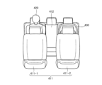
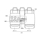
- FIG. 5 is a diagram for explaining an example of occupant detection by the occupant detection device according to the first embodiment, and is a view of the vehicle interior viewed from the front of the vehicle interior.
- FIG. 1 is a diagram illustrating a configuration example of an occupant detection system including an occupant detection device according to the present disclosure.
- FIG. 2 is a diagram illustrating an example arrangement of an occupant detection system including an occupant detection device according to the present disclosure.
- FIG. 3 is
- FIG. 6 is a diagram for explaining an example of occupant detection by the occupant detection device according to the first embodiment, and is a diagram for explaining area estimation processing.
- FIG. 7 is a diagram illustrating an example of occupant detection by the occupant detection device according to the first embodiment, and is a diagram illustrating a process of detecting a living body using radio wave intensity by a radio wave sensor.
- FIG. 8 is a diagram for explaining an example of occupant detection by the occupant detection device according to the first embodiment, and is a diagram illustrating a state in which an occupant may be left behind.
- FIG. 9 is a diagram for explaining an example of occupant detection by the occupant detection device according to the second embodiment, and is a perspective view of the inside of the vehicle interior.
- FIG. 10 is a diagram for explaining an example of occupant detection by the occupant detection device according to the second embodiment, and is a view of the vehicle interior viewed from the front of the vehicle interior.
- FIG. 11 is a diagram for explaining an example of occupant detection by the occupant detection device according to the second embodiment, and is a diagram for explaining area estimation processing.
- FIG. 12 is a diagram for explaining an example of occupant detection by the occupant detection device according to the second embodiment, and is a diagram for explaining the process of detecting a living body using the radio wave intensity by the radio wave sensor.
- FIG. 13 is a diagram for explaining an example of occupant detection by the occupant detection device according to the second embodiment, and is a diagram illustrating a state in which an occupant may be left behind.
- FIG. 11 is a diagram for explaining an example of occupant detection by the occupant detection device according to the second embodiment, and is a view of the vehicle interior viewed from the front of the vehicle interior.
- FIG. 11 is a diagram for explaining an example of
- FIG. 14 is a diagram for explaining an example of occupant detection by the occupant detection device according to the third embodiment, and is a perspective view of the inside of the vehicle interior.
- FIG. 15 is a diagram for explaining an example of occupant detection by the occupant detection device according to the third embodiment, and is a view of the vehicle interior viewed from the front of the vehicle interior.
- FIG. 16 is a diagram for explaining an example of occupant detection by the occupant detection device according to the third embodiment, and is a diagram for explaining area estimation processing.
- FIG. 17 is a diagram for explaining an example of occupant detection by the occupant detection device according to the third embodiment, and is a diagram for explaining the process of detecting a living body using the radio wave intensity by the radio wave sensor.
- FIG. 18 is a diagram illustrating another example of occupant detection by the occupant detection device according to the present disclosure.
- FIG. 19 is a diagram illustrating a first example of a hardware configuration for realizing the functions of the occupant detection device according to the present disclosure.
- FIG. 20 is a diagram illustrating a second example of a hardware configuration for realizing the functions of the occupant detection device according to the present disclosure.
- FIG. 1 is a diagram illustrating a configuration example of an occupant detection system 1 including an occupant detection device 100 according to the present disclosure.
- the occupant detection system 1 is a system that detects an occupant of a moving object.
- the occupant detection system 1 monitors the indoor situation of the moving body (inside the moving body) using the measurement results of various sensors held by the moving body.
- the occupant detection system 1 detects an occupant of a moving body by detecting, for example, the presence or absence of a living body in the room of the moving body, the number of living bodies, or the attributes of the living body.
- Living organisms include living organisms other than humans, and also include animals such as pets kept by humans.
- the occupant detection system 1 will be explained assuming that the moving object is a vehicle.
- the term "vehicle” can be replaced with "mobile body” within the scope of implementation based on common technical knowledge.
- the occupant detection system 1 shown in FIG. 1 is configured to include an occupant detection device 100, a camera 200 (imaging device), a radio wave sensor 210, and an occupant information processing device 300.
- the occupant detection device 100 is communicably connected to a camera 200, a radio wave sensor 210, and an occupant information processing device 300, respectively.
- the occupant detection device 100 and the occupant information processing device 300 are connected, for example, via a CAN (Controller Area Network).
- the occupant detection device 100 detects the presence or absence of a living body inside the vehicle using images and radio wave sensor data.
- the occupant detection device 100 detects the number of living organisms inside the vehicle using images and radio wave sensor data.
- the occupant detection device 100 detects the attributes of a living body inside the vehicle using images and radio wave sensor data.
- the occupant detection device 100 generates occupant information using at least one of the presence or absence of living organisms, the number of living organisms, and the attributes of living organisms.
- the occupant detection device 100 uses the image to estimate at least an area of interest in which a living body is likely to be present in an area blocked by vehicle equipment in the image.
- the occupant detection device 100 uses the radio wave intensity indicated by the radio wave sensor data to detect a living body present in a region of interest in a region of vehicle equipment.
- the internal configuration of the occupant detection device 100 will be described later.
- Camera 200 is an imaging device in the present disclosure.
- the camera 200 outputs a captured image (captured image).
- Camera 200 is installed to take an image of the interior of the vehicle.
- the camera 200 is installed, for example, in the front of the vehicle or at the upper front of the vehicle.
- the radio wave sensor 210 is a sensor that uses radio waves that can pass through the front seat and measure the living body in the rear seat. Radio wave sensor 210 transmits radio waves, receives reflected waves, and outputs radio signals. Radio wave sensor 210 is installed so as to transmit radio waves toward the interior of the vehicle. When the radio wave sensor 210 is more preferably installed, the radio wave sensor 210 is installed, for example, in the front of the vehicle or at the upper front of the vehicle. By being installed in this manner, the radio wave sensor 210 transmits radio waves to an area including the attention area in the vehicle interior, and receives reflected waves from the area including the attention area. Even more preferably, the installation position of camera 200 and the installation position of radio wave sensor 210 are approximately the same position. In this case, processing such as matching the coordinates inside the vehicle interior included in the image captured by the camera 200 and the coordinates of the radio wave intensity shown in the radio wave sensor data becomes unnecessary, and the processing load on the occupant detection device 100 is reduced. Ru.
- the occupant information processing device 300 acquires occupant information and performs processing using the occupant information.
- the occupant information processing device 300 is, for example, a notification device, and generates notification information using the presence or absence of living organisms, the number of living organisms, or the attributes of the living organisms that may be included in the occupant information, and outputs the notification information to an image output device (not shown).
- the information is output via an image output device (not shown), a sound output device (sound output device not shown), a terminal device, a mobile terminal, a smartphone, etc.
- the occupant information processing device 300 is not limited to the above notification device as long as it performs processing using occupant information.
- the occupant information processing device 300 may be a vehicle control device that controls the vehicle using occupant information.
- the occupant information processing device 300 may be configured to include the occupant detection device 100.
- the occupant detection device 100 includes an image acquisition section 110, an area identification section 120, dictionary data 125, an area estimation section 130, a radio wave sensor data acquisition section 140, a detection effective area/threshold optimization section 150, a living body detection section 160, and an occupant detection section 160. It is configured to include an information output section 170.
- the image acquisition unit 110 acquires an image captured by an imaging device. In a state where the occupant detection device 100 is more preferably used, the image acquisition unit 110 acquires an image of the interior of the vehicle captured by an imaging device mounted in the vehicle interior. Specifically, when the image acquisition unit 110 acquires an image signal from an imaging device, it performs separation processing of an IR image and RGB image, noise removal processing, distortion correction processing, etc., and acquires an image.
- the area identification unit 120 outputs intra-image area information that distinguishes between the vehicle equipment area, the living body area, and the object area on the seat in the image acquired by the image acquisition unit 110.
- Vehicle equipment generally refers to equipment that is already installed in a vehicle at the time the vehicle is manufactured, such as a front seat and a rear seat. Furthermore, “vehicle equipment” is equipment inside the vehicle that shields between the camera and the seat to be imaged.
- the "object” in “object on coordinates” is, for example, an object attached to a vehicle after manufacturing, such as a child seat (infant seat), or an object simply placed on a seat.
- the area identification unit 120 identifies areas for each vehicle equipment, area for each living body, and area for each object on the seat in the image acquired by the image acquisition unit 110, and identifies each of the identified areas. Output intra-image area information for differentiation. More specifically, the area identification unit 120 first acquires the image output from the image acquisition unit 110. The area identification unit 120 then performs image recognition processing using the image acquired by the image acquisition unit 110. At this time, the region identification unit 120 can improve the accuracy of region identification by performing image recognition processing, for example, with reference to dictionary data 125 (dictionary data 125 to be described later). Since image recognition itself can be realized using existing technology, detailed explanation will be omitted.
- the area identification unit 120 identifies an area for each vehicle equipment, an area for each living body, and an area for each object on the seat in the image.
- the area identification unit 120 generates intra-image area information for distinguishing between an area for each identified vehicle equipment, an area for each living body, and an area for each object on the seat.
- the intra-image area information is not limited in its form as long as it is information that can distinguish between an area for each vehicle equipment, an area for each living body, and an area for each object on the seat in the image.
- the area identification unit 120 outputs the generated intra-image area information.
- the area of the object on the seat identified by the area identification unit 120 includes a partial area of the object.
- the area of the object on the seat includes, for example, a partial area of a child seat.
- the area of the living body identified by the area identification unit 120 includes a partial area of the living body.
- the partial regions of the living body include, for example, the head, neck, chest, abdomen, lower back, thighs, and legs of
- the dictionary data 125 is learning data learned for image recognition.
- the dictionary data 125 can be appropriately referenced in the processing of the region identification section 120, the region estimation section 130, and the living body detection section 160.
- the area estimating unit 130 uses the intra-image area information output by the area identifying unit 120 to estimate, for each living body, a region of interest in which a living body is likely to be present, with respect to an occluded area caused in the image by vehicle equipment. do. Specifically, the region estimation unit 130 extracts the occluded region using the intra-image region information.
- the shielding region is a region of the vehicle equipment in the image that shields the rear seat.
- the region estimation unit 130 extracts the region of the living body and the region of the object on the seat in the image using the intra-image region information.
- the area estimating unit 130 uses the extracted area of the living body and the area of the object on the seat to estimate a region of interest where the living body is likely to be present in the shielded area.
- the region estimation unit 130 estimates a region of interest smaller than the size of the occluded region. This makes it easier for the occupant detection device 100 to detect a living body when a living body is seated with its entire body shielded by the shielding area. Furthermore, the occupant detection device 100 can more easily detect the attributes of relatively small-sized living organisms such as infants, toddlers, and children than adults, based on the size of the attention area. Further, more specifically, when the area of the object on the seat identified by the area identification unit 120 is a partial area of the child seat, the area estimation unit 130 The area of interest is estimated by estimating the entire area of the child seat using the area.
- the region estimating unit 130 estimates the region of interest in the occluded region adjacent to the living body indicated by the intra-image region information. This makes it easier for the occupant detection device 100 to detect the attributes of living organisms that are relatively smaller in size than adults, such as infants, toddlers, and children. Further, more specifically, when the region of the living body indicated in the intra-image region information is a partial region in contact with the seat surface of the rear seat, the region estimating unit 130 uses the partial region to The region of interest is estimated by estimating the region of the living body that is likely to exist over the region.
- the area estimating unit 130 further uses the intra-image area information output by the area identifying unit 120 to determine a living body detection area where a living body exists. This improves the accuracy of detecting the number of living bodies in the occupant detection device 100.
- the area estimating unit 130 outputs attention area information indicating an attention area or living body detection area information indicating a living body detection area according to the estimation result.
- the radio wave sensor data acquisition unit 140 uses the results measured by the radio wave sensor 210 to periodically acquire a radio wave intensity sensor that indicates the distribution of the radio wave intensity of reflected waves. Specifically, the radio wave sensor data acquisition unit 140 first acquires a radio wave signal that is the result of measurement by the radio wave sensor 210 for a region including the region of interest. The radio sensor data acquisition unit 140 then performs basic radio signal processing such as FFT (Fast Fourier Transform) on the radio signal to generate radio field intensity data indicating the distribution of radio field intensity from the reflector. The radio wave sensor data acquisition unit 140 periodically generates radio field intensity data and outputs the generated radio field intensity data. Radio field strength data is data that can express radio field strength in the form of point cloud data, for example, a point cloud.
- FFT Fast Fourier Transform
- the detection effective area/threshold value optimization unit 150 extracts radio field intensity data effective for detection.
- the detection effective area/threshold optimization unit 150 acquires radio field intensity data from the radio sensor data acquisition unit 140, and out of the radio field intensity data acquired by the radio sensor data acquisition unit, the detection effective area/threshold optimization unit 150 calculates the area of interest estimated by the area estimation unit. Select radio field strength data.
- the detection effective area/threshold value optimization unit 150 acquires radio field intensity data from the radio wave sensor data acquisition unit 140.
- the detection effective area/threshold optimization unit 150 acquires the area of interest information from the area estimation unit 130.
- the detection effective area/threshold optimization unit 150 determines the attention area as the detection effective area using the attention area information, and selects radio field intensity data in the attention area from among the radio field intensity data acquired by the radio wave sensor data acquisition unit. do. Thereby, the detection effective area/threshold value optimization unit 150 selects the radio field intensity sensor in the optimized detection effective area.
- the detection effective area/threshold value optimization unit 150 further uses a threshold value corresponding to the area indicated by the intra-image area information among the radio wave intensity data in the attention area estimated by the area estimating unit, and selects radio waves exceeding the threshold value. Select intensity data.
- the detection effective area/threshold optimization unit 150 sets the radio wave intensity data in the child seat area to a power that is weaker than the power intensity when directly reflected from a living body. Use a threshold that allows you to select the intensity. Thereby, the detection effective area/threshold value optimization unit 150 selects radio field intensity data using the optimal threshold value.
- the detection effective area/threshold optimization unit 150 may be configured to adjust the radio field intensity data of the area of interest.
- the detection effective area/threshold value optimization unit 150 performs signal processing to correct the radio field intensity data of the attention area according to the vehicle equipment and objects on the seats that are present in the shielding area.
- the detection effective area/threshold value optimization unit 150 performs, for example, arithmetic processing to offset the value of the radio field intensity indicated by the radio field intensity data.
- the detection effective area/threshold value optimization unit 150 performs, for example, filter processing on the value of the radio field intensity indicated by the radio field intensity data, taking into consideration time-series changes.
- the detection effective area/threshold optimization unit 150 uses the above-mentioned threshold from the adjusted radio field intensity data to select and output radio field intensity data exceeding the threshold.
- the detection target area is set in advance as shown in FIG. 18, which will be described later, when the detection effective area/threshold optimization unit 150 acquires the area of interest information from the area estimation unit 130, instead of the detection target area, The attention area is reset to the detection effective area as described above.
- the detection effective area/threshold optimization unit 150 adjusts the radio field intensity by instructing the radio sensor 210 to increase the sensitivity of the radio sensor 210 based on the radio field intensity indicated by the radio field intensity data of the region of interest. You can do it like this.
- the living body detection unit 160 detects the attributes of the living body using the intra-image area information and the radio field intensity data selected by the detection effective area/threshold optimization unit 150. Specifically, the living body detection unit 160 detects the attributes of the living body using the area for each living body in the image and the radio field intensity data for each area of interest selected by the detection effective area/threshold optimization unit 150. . More specifically, the living body detection unit 160 aggregates the temporal dispersion and cumulative strength of the radio field intensity using the radio field intensity data for each region acquired in time series, and observes the distribution of radio field strength in time series. By doing so, the size and position of the reflective object in the area to be detected is determined.
- the living body detection unit 160 detects the number of living bodies and the attributes of the living bodies using the determination results of the size and position of the reflective object in the detection target area.
- the living body detection unit 160 outputs living body information including the number of living bodies and attributes of the living bodies.
- the living body detecting unit 160 further detects attributes of the living body using the living body detection area.
- the living body detecting unit 160 further uses the living body detection area, the attention area, and the radio wave intensity to estimate the number of living bodies in the vehicle interior. To detect.
- the occupant information output unit 170 uses the detection result by the living body detection unit 160 to generate occupant information indicating the occupant riding in the vehicle, and outputs the occupant information to the occupant information processing device 300. Specifically, the occupant information output unit 170 acquires biometric information indicating the detection result of the biometric detection unit 160, and generates occupant information including the presence or absence of an occupant, the number of occupants, and attributes of the occupant. The occupant information may include information such as a flag indicating that the occupant is only an infant, a flag indicating that the occupant is only an infant or child, and a flag indicating that there is a possibility that the vehicle will be left behind. The occupant information output unit 170 outputs the occupant information to the occupant information processing device 300.
- FIG. 2 is a diagram illustrating an example arrangement of the occupant detection system 1 including the occupant detection device 100 according to the present disclosure.
- FIG. 2 shows a cutaway side view of a vehicle 400 equipped with the occupant detection system 1.
- the occupant detection device 100 and the occupant information processing device 300 are arranged at the front of the vehicle interior 410.
- the camera 200 is installed, for example, in the vehicle interior 410 at the front or upper front of the vehicle.
- the radio wave sensor 210 is installed, for example, in the front or upper front of the vehicle inside the vehicle interior.
- the installation position of camera 200 and the installation position of radio wave sensor 210 are approximately the same position.
- the front seat 411 which is a vehicle equipment, becomes a shield, and a blind spot 415 occurs on the rear seat 412 side.
- the occupant detection device 100 uses the measurement results of the radio wave sensor 210 to detect the area of the occupant in the image captured by the camera 200, even when an occupant such as an infant, toddler, or child is present in the blind spot 415. It is possible to detect.
- FIG. 3 is a flowchart illustrating an example of processing of the occupant detection device 100 according to the present disclosure.
- the occupant detection device 100 starts the process shown in FIG. 3, for example, when the imaging device starts capturing an image.
- the occupant detection device 100 starts the process shown in FIG. 3, for example, when the engine of the vehicle is turned off or when the driver gets off the vehicle.
- the occupant detection device 100 starts the loop process shown in FIG. 3 (step ST100).
- the occupant detection device 100 executes image acquisition processing (step ST101). Specifically, upon acquiring an image signal from an imaging device, the image acquisition unit 110 in the occupant detection device 100 performs separation processing of an IR image and RGB image, noise removal processing, distortion correction processing, etc., and processes the image. get. The image acquisition unit 110 outputs the acquired image to the area identification unit 120.
- the occupant detection device 100 executes area identification processing (step ST102). Specifically, the area identification unit 120 in the occupant detection device 100 first acquires the image output from the image acquisition unit 110. The area identification unit 120 then performs image recognition processing using the image acquired by the image acquisition unit 110. The area identification unit 120 identifies an area for each vehicle equipment, an area for each living body, and an area for each object on the seat in the image. The area identification unit 120 generates intra-image area information for distinguishing between an area for each identified vehicle equipment, an area for each living body, and an area for each object on the seat. The area identification unit 120 outputs the generated intra-image area information.
- the occupant detection device 100 executes area estimation processing (step ST103). Specifically, the area estimation unit 130 in the occupant detection device 100 first obtains intra-image area information from the area identification unit 120. The region estimating unit 130 uses the intra-image region information to extract a shielding region, which is a region that shields the rear seat, from the vehicle equipment region in the image. Furthermore, the region estimating unit 130 uses the intra-image region information to extract the region of the living body and the region of the object on the seat in the image. The area estimating unit 130 uses the extracted area of the living body and the area of the object on the seat to estimate a region of interest where the living body is likely to be present in the shielded area.
- a shielding region which is a region that shields the rear seat
- the area estimating unit 130 estimates the area of the living body that is likely to be covered by the shielding area using the position of the partial area of the living body, and estimates a region of interest that includes the estimated area. Further, the area estimating unit 130 estimates the entire area of the child seat using, for example, a partial area of the child seat, and estimates a region of interest that includes the estimated area. Further, the region estimating unit 130 uses, for example, a partial region of the living body to estimate the entire region of the living body that would exist across the partial region and the occluded region, and estimates a region of interest that includes the estimated region. .
- the occupant detection device 100 executes a radio wave sensor data acquisition process (step ST104). Specifically, the radio wave sensor data acquisition unit 140 in the occupant detection device 100 first acquires a radio wave signal that is the result of measurement by the radio wave sensor 210 for an area including the attention area.
- the occupant detection device 100 executes signal processing (step ST105). Specifically, the radio sensor data acquisition unit 140 in the occupant detection device 100 performs basic radio signal processing on the radio signal to generate radio field intensity data indicating the distribution of radio field intensity from the reflector. The radio wave sensor data acquisition unit 140 periodically generates radio field intensity data and outputs the generated radio field intensity data.
- the occupant detection device 100 executes detection effective area/threshold optimization processing to select radio field intensity data effective for detection (step ST106). Specifically, the detection effective area/threshold value optimization unit 150 in the occupant detection device 100 first acquires radio field intensity data from the radio wave sensor data acquisition unit 140. Furthermore, the detection effective area/threshold optimization unit 150 acquires attention area information from the area estimation unit 130. Next, the detection effective area/threshold optimization unit 150 determines the attention area as the detection effective area using the attention area information, and determines the radio wave intensity in the attention area from the radio field intensity data acquired by the radio wave sensor data acquisition unit. Select data. Thereby, the detection effective area/threshold value optimization unit 150 selects the radio field intensity sensor in the optimized detection effective area.
- the detection effective area/threshold optimization unit 150 further adjusts the threshold by using a threshold corresponding to the area indicated by the intra-image area information out of the radio wave intensity data in the attention area estimated by the area estimation unit. Select the radio field strength data that exceeds the specified range. Thereby, the detection effective area/threshold value optimization unit 150 selects radio field intensity data using the optimized threshold value.
- the detection effective area/threshold value optimization unit 150 may be configured to adjust the radio field intensity data of the area of interest. In this case, the detection effective area/threshold value optimization unit 150 performs signal processing to correct the radio field intensity data of the attention area according to the vehicle equipment and objects on the seats that are present in the shielding area.
- the detection effective area/threshold value optimization unit 150 performs, for example, arithmetic processing to offset the value of the radio field intensity indicated by the radio field intensity data.
- the detection effective area/threshold value optimization unit 150 performs, for example, filter processing on the value of the radio field intensity indicated by the radio field intensity data, taking into consideration time-series changes.
- the detection effective area/threshold optimization unit 150 uses the above-mentioned threshold from the adjusted radio field intensity data to select and output radio field intensity data exceeding the threshold.
- the detection effective area/threshold optimization unit 150 also instructs the radio sensor 210 to increase the sensitivity of the radio sensor 210 based on the radio field intensity indicated by the radio field intensity data of the region of interest. may be adjusted.
- the occupant detection device 100 executes a living body detection process (step ST107). Specifically, the living body detection unit 160 in the occupant detection device 100 acquires the radio field intensity data selected by the detection effective area/threshold value optimization unit in time series, and uses the radio field intensity data to calculate the temporal radio wave intensity. The size and position of the reflective object in the detection target area are determined by summing up the intensity dispersion and integrated intensity and observing the distribution of radio wave intensity in time series. The living body detection unit 160 detects the number of living bodies and the attributes of the living bodies using the determination results of the size and position of the reflective object in the detection target area. The living body detection unit 160 outputs living body information including the number of living bodies and attributes of the living bodies to the occupant information output unit 170.
- the occupant detection device 100 executes occupant information output processing (step ST108). Specifically, the occupant information output unit 170 in the occupant detection device 100 acquires biometric information indicating the detection result of the biometric detection unit 160. The occupant information output unit 170 uses biometric information to generate occupant information including the presence or absence of occupants, the number of occupants, and attributes of the occupants. The occupant information output unit 170 outputs the occupant information to the occupant information processing device 300.
- the occupant detection device 100 After executing the occupant information output process in step ST108, the occupant detection device 100 repeats the process from step ST101.
- the occupant detection device 100 ends the process shown in FIG. 3, for example, when the imaging device finishes imaging.
- FIG. 4 is a diagram for explaining an example of occupant detection by the occupant detection device 100 according to the first embodiment, and is a perspective view of the interior of the vehicle.
- FIG. 5 is a diagram for explaining an example of occupant detection by the occupant detection device 100 according to the first embodiment, and is a view of the vehicle interior viewed from the front of the vehicle interior.
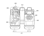
- FIG. 6 is a diagram for explaining an example of occupant detection by the occupant detection device 100 according to the first embodiment, and is a diagram for explaining area estimation processing.
- FIG. 4 is a diagram for explaining an example of occupant detection by the occupant detection device 100 according to the first embodiment, and is a perspective view of the interior of the vehicle.
- FIG. 5 is a diagram for explaining an example of occupant detection by the occupant detection device 100 according to the first embodiment, and is a view of the vehicle interior viewed from the front of the vehicle interior.
- FIG. 6 is a diagram for explaining an example of occupant detection by the occupant detection device 100 according to the first embodiment, and
- FIG. 7 is a diagram for explaining an example of occupant detection by the occupant detection device 100 according to the first embodiment, and is a diagram for explaining a process of detecting a living body using the radio wave intensity by the radio wave sensor 210.
- FIG. 8 is a diagram for explaining an example of occupant detection by the occupant detection device 100 according to the first embodiment, and is a diagram illustrating a state in which an occupant may be left behind. Arrow A in FIG. 4 indicates the direction seen from the installation position of the camera 200, for example.
- a living body 420 is seated on the left side facing the rear seat 412, and a child seat 430 is installed on the right side.
- a living body 440 having attributes such as an infant is seated in the child seat 430 .
- the passenger seat 411-2 of the front seat 411 becomes a shield, creating a blind spot, as shown in FIG.
- the living body 440 (infant) seated in the child seat 430 is shielded by the shielding area by the front passenger seat 411-2 of the front seat 411, so the infant is detected. Can not.
- the area identification unit 120 identifies the areas of the driver's seat 411-1 and passenger seat 411-2 of the front seats 411, and the area of the rear seat 412 as vehicle equipment areas. Further, the area identification unit 120 identifies the area of the living body 420. Furthermore, the area identification unit 120 identifies a partial area of the child seat 430 as an area of an object on the seat.
- the region estimation unit 130 estimates a region of interest 455 as shown in FIG. Specifically, the area estimation unit 130 estimates the entire area of the child seat 430 using the partial area of the child seat 430, and based on the entire area of the child seat 430, determines an area of interest where a living body 440 such as an infant is likely to exist. Estimate 455. At this time, the area estimation unit 130 may also estimate the entire area of the living body 420 using the partial area of the living body 420, and determine the living body detection area 450 based on the entire area of the living body 420.
- the living body detection section 160 After processing by the radio wave sensor data acquisition section 140 and the detection effective area/threshold value optimization section 150, the living body detection section 160 obtains the data illustrated in FIG. 7.
- the living body detection unit 160 detects a living body 440 having an attribute such as an infant using the region of the child seat 430 included in the image and the radio wave intensity 465 obtained in the region of interest 455.
- the occupant detection device includes an image acquisition unit that acquires an image captured by an imaging device, and an area of vehicle equipment, a region of a living body, and an area of an object on a seat in the image acquired by the image acquisition unit. an area identification unit that outputs area information in the image that distinguishes between the two areas; and an area identification unit that outputs area information in the image that distinguishes between an area estimator that estimates the area of interest that will be noticed for each living organism; and a radio wave sensor that uses the results measured by the radio wave sensor to acquire radio field intensity data in chronological order that indicates the distribution of the radio field intensity of reflected waves.
- a detection effective area/threshold optimization unit that selects radio field intensity data in the region of interest estimated by the area estimation unit from among the radio field intensity data acquired by the data acquisition unit and the radio wave sensor data acquisition unit;
- a living body detecting unit that detects the attributes of a living body using the radio field intensity data selected by the detection effective area/threshold optimization unit, and generating occupant information indicating the occupant of the vehicle using the detection result by the living body detecting unit.
- an occupant information output section that outputs the occupant information to an occupant information processing device.
- the occupant detection method includes an image acquisition step in which an image acquisition unit acquires an image captured by an imaging device, and an area identification unit that identifies an area of vehicle equipment in the image acquired by the image acquisition unit. a region identification step of outputting intra-image region information that distinguishes between a region of the living body and an object region on the seat; A region estimation step for estimating a region of interest in which a living organism is likely to be present for each living organism in a shielded region generated in the image by the equipment, and a radio wave sensor data acquisition unit using the results measured by the radio wave sensor.
- the detection effective area/threshold optimization step selects the radio wave intensity data in the attention area estimated by the area estimating unit
- the living body detection unit selects the radio wave intensity data selected by the detection effective area/threshold optimizing unit.
- the detection effective area/threshold value optimization unit further includes a radio wave intensity data in the area of interest estimated by the area estimating unit that corresponds to the area indicated by the intra-image area information.
- the configuration is such that a threshold value is used to select radio field intensity data exceeding the threshold value.
- the area estimation unit is configured to estimate the attention area smaller than the size of the shielding area.
- the present disclosure has the effect of making it easier to detect occupants who are relatively small in size, such as infants, toddlers, and children, compared to adults. Further, an occupant detection method to which this is applied produces effects similar to those described above.
- the area of the object on the seat identified by the area identification unit is a partial area of a child seat
- the area estimating unit is configured to detect an object on the seat identified by the area identification unit.
- the device is configured to estimate the region of interest by estimating the entire region of the child seat using the region of the object.
- the area estimating unit uses the partial area to The area of interest is estimated by estimating the area of the living body that is likely to exist across the area and the occluded area.
- the present disclosure has the effect that, for example, it becomes easier to detect an occupant lying on a rear seat. Further, an occupant detection method to which this is applied produces effects similar to those described above.
- the area estimating unit further determines a living body detection area where a living body exists, using the in-image area information output by the area identifying unit, and the living body detecting unit , and further configured to detect the attributes of the living body using the living body detection area.
- the living body detection unit is further configured to detect the number of living bodies in the vehicle interior using the living body detection area, the attention area, and the radio field intensity.
- the present disclosure has the effect that the accuracy of detecting the number of living organisms can be further improved. Further, an occupant detection method to which this is applied produces effects similar to those described above.
- Embodiment 2 a second example of occupant detection by the occupant detection device 100 will be described.
- description of the configuration described in Embodiment 1 will be omitted as appropriate.
- the configuration example of the occupant detection device 100 according to the second embodiment is the same as the configuration example of the occupant detection device 100 described in the first embodiment, so a detailed description of the configuration example will be omitted.
- FIG. 9 is a diagram for explaining an example of occupant detection by the occupant detection device 100 according to the second embodiment, and is a perspective view of the interior of the vehicle.
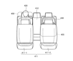
- FIG. 10 is a diagram for explaining an example of occupant detection by the occupant detection device 100 according to the second embodiment, and is a view of the vehicle interior viewed from the front of the vehicle interior.
- FIG. 11 is a diagram for explaining an example of occupant detection by the occupant detection device 100 according to the second embodiment, and is a diagram for explaining area estimation processing.
- FIG. 9 is a diagram for explaining an example of occupant detection by the occupant detection device 100 according to the second embodiment, and is a perspective view of the interior of the vehicle.
- FIG. 10 is a diagram for explaining an example of occupant detection by the occupant detection device 100 according to the second embodiment, and is a view of the vehicle interior viewed from the front of the vehicle interior.
- FIG. 11 is a diagram for explaining an example of occupant detection by the occupant detection device 100 according to the second embodiment, and
- FIG. 12 is a diagram for explaining an example of occupant detection by the occupant detection device 100 according to the second embodiment, and is a diagram for explaining the process of detecting a living body using the radio wave intensity by the radio wave sensor 210.
- FIG. 13 is a diagram for explaining an example of occupant detection by the occupant detection device 100 according to the second embodiment, and is a diagram illustrating a state in which an occupant may be left behind. Arrow B in FIG. 9 indicates the direction seen from the installation position of the camera 200, for example.
- a living body 520 is seated in a portion closer to the center of the right seat facing the rear seat 412.
- the front passenger seat 411-2 of the front seat 411 becomes a shield, creating a blind spot, as shown in FIG.
- the image captured by camera 200 includes a partial region of living body 520, living body 540 cannot be detected.
- the area identification unit 120 identifies the areas of the driver's seat 411-1 and passenger seat 411-2 of the front seats 411, and the area of the rear seat 412 as vehicle equipment areas. Further, the region identification unit 120 identifies the region of the living body 520.
- the region estimation unit 130 estimates a region of interest 555 as shown in FIG. Specifically, the region estimating unit 130 determines that since the sitting position of the living body 520 is closer to the center than the right seat, there is a possibility that the living body 540 is seated on the right side. A region of interest 555 that is likely to exist is estimated. At this time, the area estimation unit 130 may also estimate the entire area of the living body 520 using the partial area of the living body 520, and determine the living body detection area 550 based on the entire area of the living body 520.
- the living body detection section 160 After processing by the radio wave sensor data acquisition section 140 and the detection effective area/threshold value optimization section 150, the living body detection section 160 obtains the data illustrated in FIG. 12.
- the living body detection unit 160 detects a living body 540 having an attribute such as an infant or a child using the radio wave intensity 465 obtained in the partial region of the living body 520 included in the image and the region of interest 555.
- the areas of two living bodies are identified in the image, and the area of interest where the living body (infant) sitting sandwiched between the two living bodies is likely to be located is estimated. It may be something that does.
- the region estimation unit is configured to estimate the region of interest in the shielded region adjacent to the living body indicated in the intra-image region information.
- the present disclosure has the effect of making it easier to detect occupants such as infants, young children, and children. Further, an occupant detection method to which this is applied produces effects similar to those described above.
- Embodiment 3 a third example of occupant detection by the occupant detection device 100 will be described.
- description of Embodiment 1 or the configuration described in Embodiment 2 will be omitted as appropriate.
- the configuration example of the occupant detection device 100 according to the third embodiment is the same as the configuration example of the occupant detection device 100 described in the first embodiment, so a detailed description of the configuration example will be omitted.
- FIG. 14 is a diagram for explaining an example of occupant detection by the occupant detection device 100 according to the third embodiment, and is a perspective view of the inside of the vehicle interior.
- FIG. 15 is a diagram for explaining an example of occupant detection by the occupant detection device 100 according to the third embodiment, and is a view of the vehicle interior viewed from the front of the vehicle interior.
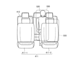
- FIG. 16 is a diagram for explaining an example of occupant detection by the occupant detection device 100 according to the third embodiment, and is a diagram for explaining area estimation processing.
- FIG. 14 is a diagram for explaining an example of occupant detection by the occupant detection device 100 according to the third embodiment, and is a perspective view of the inside of the vehicle interior.
- FIG. 15 is a diagram for explaining an example of occupant detection by the occupant detection device 100 according to the third embodiment, and is a view of the vehicle interior viewed from the front of the vehicle interior.
- FIG. 16 is a diagram for explaining an example of occupant detection by the occupant detection device 100 according to the third embodiment
- FIG. 17 is a diagram for explaining an example of occupant detection by the occupant detection device 100 according to the third embodiment, and is a diagram for explaining the process of detecting a living body using the radio wave intensity by the radio wave sensor 210.
- Arrow C in FIG. 14 indicates the direction seen from the installation position of camera 200, for example.
- the area identification unit 120 identifies the areas of the driver's seat 411-1 and passenger seat 411-2 of the front seats 411, and the area of the rear seat 412 as vehicle equipment areas. Further, the area identification unit 120 identifies a partial area 620a of the living body 620.
- the region estimation unit 130 estimates a region of interest 650 as shown in FIG. 16. Specifically, the region estimation unit 130 determines whether the partial region 620a in contact with the rear seat 412 is any part of the living body 620 (the head, neck, chest, abdomen, lower back, thighs, or legs of the living body). ), and further estimates the physique of the whole body from the parts of the living body 620, and estimates a region of interest 650 of a size corresponding to the physique of the whole body.
- the living body detection section 160 After processing by the radio wave sensor data acquisition section 140 and the detection effective area/threshold value optimization section 150, the living body detection section 160 obtains the data illustrated in FIG. 17.
- the living body detection unit 160 detects a living body 620 having an attribute such as an infant or a child using a partial region 620a of the living body 620 included in the image and the radio wave intensity 660 obtained in the attention area 650.
- the occupant information output unit 170 of the occupant detection device 100 outputs information that the occupant is only an infant, information that the occupant is only an infant or child, or information that there is a possibility of the occupant being left behind. It is possible to output information such as:
- the area estimating unit uses the partial area to The area of interest is estimated by estimating the area of the living body that is likely to exist across the area and the occluded area. This has the effect of, for example, making it easier to detect a passenger lying in the rear seat. Further, an occupant detection method to which this is applied produces effects similar to those described above.
- FIG. 18 is a diagram illustrating another example of occupant detection by the occupant detection device 100 according to the present disclosure.
- the detection target regions 761, 762, and 763 for each rear seat shown in FIG. 18 may be set before setting the region of interest estimated by the region estimation unit 130.
- the region estimating section 130 resets the detection target regions 761, 762, and 763 that have been set in advance as the region of interest.
- FIG. 19 is a diagram illustrating a first example of a hardware configuration for realizing the functions of the occupant detection device 100 according to the present disclosure.
- FIG. 20 is a diagram illustrating a second example of a hardware configuration for realizing the functions of the occupant detection device 100 according to the present disclosure.
- the occupant detection device 100 of the present disclosure is realized by hardware as shown in FIG. 19 or 20.
- the occupant detection device 100 includes a processor 10001 and a memory 10002.
- the processor 10001 and the memory 10002 are, for example, installed in a computer.
- the memory 10002 includes the computer, an image acquisition section 110, an area identification section 120, an area estimation section 130, a radio wave sensor data acquisition section 140, a detection effective area/threshold optimization section 150, a living body detection section 160, and an occupant information output section. 170, and a program for functioning as a control section (not shown) is stored.
- the processor 10001 When the processor 10001 reads and executes the program stored in the memory 10002, the image acquisition unit 110, area identification unit 120, area estimation unit 130, radio wave sensor data acquisition unit 140, detection effective area/threshold optimization unit 150, The functions of a living body detection section 160, an occupant information output section 170, and a control section (not shown) are realized. Furthermore, the memory 10002 or another memory (not shown) realizes dictionary data 125 and a storage unit (not shown).
- the processor 10001 uses, for example, a CPU (Central Processing Unit), a GPU (Graphics Processing Unit), a microprocessor, a microcontroller, or a DSP (Digital Signal Processor).
- a CPU Central Processing Unit
- GPU Graphics Processing Unit
- microprocessor a microcontroller
- DSP Digital Signal Processor
- the memory 10002 includes RAM (Random Access Memory), ROM (Read Only Memory), EPROM (Erasable Programmable ROM), and EEPROM (Electrically Erasable Pro Non-volatile or volatile semiconductor memory such as grammable Read Only Memory) or flash memory Alternatively, it may be a magnetic disk such as a hard disk or a flexible disk, an optical disk such as a CD (Compact Disc) or a DVD (Digital Versatile Disc), or a magneto-optical disk.
- Processor 10001 and memory 10002 are connected so that they can mutually transmit data.
- the processor 10001 and the memory 10002 are connected to other hardware via an input/output interface 10003 so that they can mutually transmit data.
- the functions of the section may be realized by a dedicated processing circuit 10004, as shown in FIG.
- the processing circuit 10004 may be, for example, a single circuit, a composite circuit, a programmed processor, a parallel programmed processor, an ASIC (Application Specific Integrated Circuit), a PLD (Programmable Logic Device), or an FPGA (Field-Program). Ambable Gate Array), SoC (System-on-a-Chip) or system LSI (Large-Scale Integration).
- the memory 10005 or another memory (not shown) realizes dictionary data 125 and a storage unit (not shown).
- the memory 10005 includes RAM (Random Access Memory), ROM (Read Only Memory), EPROM (Erasable Programmable ROM), and EEPROM (Electrically Erasable Pro Non-volatile or volatile semiconductor memory such as grammable Read Only Memory or flash memory Alternatively, it may be a magnetic disk such as a hard disk or a flexible disk, an optical disk such as a CD (Compact Disc) or a DVD (Digital Versatile Disc), or a magneto-optical disk. Processing circuit 10004 and memory 10005 are connected so that they can mutually transmit data.
- processing circuit 1004 and the memory 10005 are connected to other hardware via an input/output interface 10006 so as to be able to mutually transmit data.
- image acquisition unit 110, area identification unit 120, area estimation unit 130, radio wave sensor data acquisition unit 140, detection effective area/threshold optimization unit 150, living body detection unit 160, occupant information output unit 170, and control (not shown)
- the functions of the sections may be realized by separate processing circuits, or may be realized by a processing circuit all together.
- Part of the functions of the unit may be realized by the processor 10001 and the memory 10002, and the remaining functions may be realized by the processing circuit 10004.
- the occupant detection device according to the present disclosure is particularly suitable for use in a vehicle occupant detection device because it can easily detect the attributes of living organisms such as infants, young children, and children.
- 1 Occupant detection system 100 Occupant detection device, 110 Image acquisition unit, 120 Area identification unit, 125 Dictionary data, 130 Area estimation unit, 140 Radio sensor data acquisition unit, 150 Detection effective area/threshold optimization unit, 160 Living body detection unit , 170 Occupant information output section, 200 Camera (imaging device), 210 Radio wave sensor, 300 Occupant information processing device, 400 Vehicle, 410 Vehicle interior, 411 Front seat, 411-1 Driver's seat, 411-2 Passenger seat, 412 Rear Seat, 415 Shielding area, 420 Living body (occupant), 430 Child seat (object on seat), 440 Living body (occupant), 450 Living body detection area, 455 Attention area, 460 Radio wave intensity, 465 Radio wave intensity, 520 Living body (occupant), 540 living body (occupant), 550 living body detection area, 555 attention area, 560 radio wave intensity, 620 living body (occupant), 620a partial area, 650 attention area, 660 radio wave intensity, 761,762,763 detection target area, 10001 processor
Landscapes
- Engineering & Computer Science (AREA)
- Radar, Positioning & Navigation (AREA)
- Remote Sensing (AREA)
- Physics & Mathematics (AREA)
- General Physics & Mathematics (AREA)
- Theoretical Computer Science (AREA)
- Computer Networks & Wireless Communication (AREA)
- Multimedia (AREA)
- Electromagnetism (AREA)
- Human Computer Interaction (AREA)
- Computer Vision & Pattern Recognition (AREA)
- Mechanical Engineering (AREA)
- Geophysics And Detection Of Objects (AREA)
- Fittings On The Vehicle Exterior For Carrying Loads, And Devices For Holding Or Mounting Articles (AREA)
- Image Analysis (AREA)
Priority Applications (3)
| Application Number | Priority Date | Filing Date | Title |
|---|---|---|---|
| PCT/JP2022/017075 WO2023195060A1 (ja) | 2022-04-05 | 2022-04-05 | 乗員検知装置および乗員検知方法 |
| DE112022006562.1T DE112022006562B4 (de) | 2022-04-05 | 2022-04-05 | Insassendetektionsvorrichtung und Insassendetektionsverfahren |
| JP2024513587A JP7499997B2 (ja) | 2022-04-05 | 2022-04-05 | 乗員検知装置および乗員検知方法 |
Applications Claiming Priority (1)
| Application Number | Priority Date | Filing Date | Title |
|---|---|---|---|
| PCT/JP2022/017075 WO2023195060A1 (ja) | 2022-04-05 | 2022-04-05 | 乗員検知装置および乗員検知方法 |
Publications (1)
| Publication Number | Publication Date |
|---|---|
| WO2023195060A1 true WO2023195060A1 (ja) | 2023-10-12 |
Family
ID=88242649
Family Applications (1)
| Application Number | Title | Priority Date | Filing Date |
|---|---|---|---|
| PCT/JP2022/017075 Ceased WO2023195060A1 (ja) | 2022-04-05 | 2022-04-05 | 乗員検知装置および乗員検知方法 |
Country Status (3)
| Country | Link |
|---|---|
| JP (1) | JP7499997B2 (https=) |
| DE (1) | DE112022006562B4 (https=) |
| WO (1) | WO2023195060A1 (https=) |
Cited By (2)
| Publication number | Priority date | Publication date | Assignee | Title |
|---|---|---|---|---|
| WO2025253567A1 (ja) * | 2024-06-06 | 2025-12-11 | 三菱電機モビリティ株式会社 | 情報処理装置および情報処理方法 |
| CN121121709A (zh) * | 2025-11-07 | 2025-12-12 | 阿维塔科技(重庆)股份有限公司 | 一种车内物品检测方法和车辆 |
Citations (4)
| Publication number | Priority date | Publication date | Assignee | Title |
|---|---|---|---|---|
| JP2019217830A (ja) * | 2018-06-15 | 2019-12-26 | アイシン精機株式会社 | 乗員認識装置 |
| WO2021124548A1 (ja) * | 2019-12-20 | 2021-06-24 | 三菱電機株式会社 | 車内監視装置、車内監視システム、及び車内監視方法 |
| WO2021234836A1 (ja) * | 2020-05-20 | 2021-11-25 | 三菱電機株式会社 | 車室内検知装置、および、車室内検知方法 |
| WO2021240777A1 (ja) * | 2020-05-29 | 2021-12-02 | 三菱電機株式会社 | 乗員検出装置および乗員検出方法 |
Family Cites Families (1)
| Publication number | Priority date | Publication date | Assignee | Title |
|---|---|---|---|---|
| JP2019123354A (ja) | 2018-01-16 | 2019-07-25 | 株式会社デンソー | 乗員検知装置 |
-
2022
- 2022-04-05 WO PCT/JP2022/017075 patent/WO2023195060A1/ja not_active Ceased
- 2022-04-05 DE DE112022006562.1T patent/DE112022006562B4/de active Active
- 2022-04-05 JP JP2024513587A patent/JP7499997B2/ja active Active
Patent Citations (4)
| Publication number | Priority date | Publication date | Assignee | Title |
|---|---|---|---|---|
| JP2019217830A (ja) * | 2018-06-15 | 2019-12-26 | アイシン精機株式会社 | 乗員認識装置 |
| WO2021124548A1 (ja) * | 2019-12-20 | 2021-06-24 | 三菱電機株式会社 | 車内監視装置、車内監視システム、及び車内監視方法 |
| WO2021234836A1 (ja) * | 2020-05-20 | 2021-11-25 | 三菱電機株式会社 | 車室内検知装置、および、車室内検知方法 |
| WO2021240777A1 (ja) * | 2020-05-29 | 2021-12-02 | 三菱電機株式会社 | 乗員検出装置および乗員検出方法 |
Cited By (3)
| Publication number | Priority date | Publication date | Assignee | Title |
|---|---|---|---|---|
| WO2025253567A1 (ja) * | 2024-06-06 | 2025-12-11 | 三菱電機モビリティ株式会社 | 情報処理装置および情報処理方法 |
| CN121121709A (zh) * | 2025-11-07 | 2025-12-12 | 阿维塔科技(重庆)股份有限公司 | 一种车内物品检测方法和车辆 |
| CN121121709B (zh) * | 2025-11-07 | 2026-04-03 | 阿维塔科技(重庆)股份有限公司 | 一种车内物品检测方法和车辆 |
Also Published As
| Publication number | Publication date |
|---|---|
| JPWO2023195060A1 (https=) | 2023-10-12 |
| DE112022006562T5 (de) | 2025-01-23 |
| DE112022006562B4 (de) | 2025-09-18 |
| JP7499997B2 (ja) | 2024-06-14 |
Similar Documents
| Publication | Publication Date | Title |
|---|---|---|
| JP7399283B2 (ja) | 乗員検出装置、子供置き去り警報システム、乗員検出方法および子供置き去り警報方法 | |
| JP7499997B2 (ja) | 乗員検知装置および乗員検知方法 | |
| US11709242B2 (en) | Method for detecting a living being on a seat of a vehicle, detection arrangement and vehicle | |
| US12145596B2 (en) | Cabin-inside detection device and cabin-inside detection method | |
| JP7154443B2 (ja) | 車内監視装置、車内監視システム、及び車内監視方法 | |
| JPWO2021124548A5 (https=) | ||
| JP7552645B2 (ja) | 乗員検知装置及びプログラム | |
| WO2021240769A1 (ja) | 乗員検出装置および乗員検出方法 | |
| JP7446545B2 (ja) | 乗員監視装置、および、乗員監視方法 | |
| US20230408679A1 (en) | Occupant determination apparatus and occupant determination method | |
| US20220194386A1 (en) | Disembarkation action determination device, vehicle, disembarkation action determination method, and non-transitory storage medium stored with program | |
| JPWO2021001943A1 (ja) | 車載用画像処理装置、および、車載用画像処理方法 | |
| US12518613B2 (en) | In-vehicle monitoring device, in-vehicle monitoring system, and in-vehicle monitoring method | |
| JP6594595B2 (ja) | 運転不能状態判定装置および運転不能状態判定方法 | |
| JPWO2019207625A1 (ja) | 乗員検知装置、乗員検知方法及び乗員検知システム | |
| JP2019074965A (ja) | 運転不能状態検出装置及び運転不能状態検出システム | |
| JPWO2020008568A1 (ja) | 報知対象検知装置、警報システムおよび報知対象検知方法 | |
| JPWO2022172400A5 (ja) | 車両監視装置、車両監視システム、及び車両監視方法 | |
| CN117068004A (zh) | 乘坐者保护辅助装置 | |
| CN101124610A (zh) | 图像处理方法、图像处理系统、图像处理装置及计算机程序 | |
| KR102908997B1 (ko) | 알코올 인터락 제어 장치 및 방법 | |
| JPH09210773A (ja) | 在席検知装置 | |
| US12397731B2 (en) | System for determining type of passenger | |
| JP2019074963A (ja) | 所定部位検出装置及び所定部位検出システム | |
| JP7003332B2 (ja) | 運転者監視装置及び運転者監視方法 |
Legal Events
| Date | Code | Title | Description |
|---|---|---|---|
| 121 | Ep: the epo has been informed by wipo that ep was designated in this application |
Ref document number: 22936460 Country of ref document: EP Kind code of ref document: A1 |
|
| ENP | Entry into the national phase |
Ref document number: 2024513587 Country of ref document: JP Kind code of ref document: A |
|
| WWE | Wipo information: entry into national phase |
Ref document number: 112022006562 Country of ref document: DE |
|
| 122 | Ep: pct application non-entry in european phase |
Ref document number: 22936460 Country of ref document: EP Kind code of ref document: A1 |
|
| WWG | Wipo information: grant in national office |
Ref document number: 112022006562 Country of ref document: DE |