WO2023195052A1 - 接触判定方法及び接触判定装置 - Google Patents
接触判定方法及び接触判定装置 Download PDFInfo
- Publication number
- WO2023195052A1 WO2023195052A1 PCT/JP2022/017065 JP2022017065W WO2023195052A1 WO 2023195052 A1 WO2023195052 A1 WO 2023195052A1 JP 2022017065 W JP2022017065 W JP 2022017065W WO 2023195052 A1 WO2023195052 A1 WO 2023195052A1
- Authority
- WO
- WIPO (PCT)
- Prior art keywords
- electrode
- capacitance
- contact
- steering wheel
- threshold
- Prior art date
Links
- 238000000034 method Methods 0.000 title claims abstract description 52
- 230000002159 abnormal effect Effects 0.000 claims abstract description 48
- 238000001514 detection method Methods 0.000 claims abstract description 26
- 239000012212 insulator Substances 0.000 claims abstract description 12
- 230000007423 decrease Effects 0.000 claims description 14
- 238000010030 laminating Methods 0.000 claims description 5
- 230000002093 peripheral effect Effects 0.000 abstract description 3
- 230000005856 abnormality Effects 0.000 description 28
- 239000004744 fabric Substances 0.000 description 9
- 238000010586 diagram Methods 0.000 description 8
- 239000002184 metal Substances 0.000 description 6
- 230000000052 comparative effect Effects 0.000 description 5
- 230000004044 response Effects 0.000 description 5
- 230000007547 defect Effects 0.000 description 4
- 230000006870 function Effects 0.000 description 3
- 238000007747 plating Methods 0.000 description 3
- 101150059215 AEP1 gene Proteins 0.000 description 2
- 101100079445 Arabidopsis thaliana NCA1 gene Proteins 0.000 description 2
- 230000002950 deficient Effects 0.000 description 2
- 238000009434 installation Methods 0.000 description 2
- 239000011347 resin Substances 0.000 description 2
- 229920005989 resin Polymers 0.000 description 2
- JOYRKODLDBILNP-UHFFFAOYSA-N Ethyl urethane Chemical compound CCOC(N)=O JOYRKODLDBILNP-UHFFFAOYSA-N 0.000 description 1
- 238000013459 approach Methods 0.000 description 1
- 230000000694 effects Effects 0.000 description 1
- 230000005611 electricity Effects 0.000 description 1
- 238000011900 installation process Methods 0.000 description 1
- 239000011810 insulating material Substances 0.000 description 1
- 239000010985 leather Substances 0.000 description 1
- 239000000463 material Substances 0.000 description 1
- 239000007787 solid Substances 0.000 description 1
Images


Classifications
-
- B—PERFORMING OPERATIONS; TRANSPORTING
- B62—LAND VEHICLES FOR TRAVELLING OTHERWISE THAN ON RAILS
- B62D—MOTOR VEHICLES; TRAILERS
- B62D1/00—Steering controls, i.e. means for initiating a change of direction of the vehicle
- B62D1/02—Steering controls, i.e. means for initiating a change of direction of the vehicle vehicle-mounted
- B62D1/04—Hand wheels
- B62D1/06—Rims, e.g. with heating means; Rim covers
Definitions
- the present invention relates to a contact determination method and a contact determination device for determining a driver's contact with a steering wheel.
- WO2021/095478 discloses a technology in which two electrodes are provided on the outer periphery of a steering wheel, overlapping each other with an insulator interposed therebetween, to determine whether a driver is touching the steering wheel.
- a steering wheel is often a complex surface rather than a flat surface. Therefore, when attaching the sheet-shaped electrodes and insulators to the steering wheel, it is necessary to attach the sheet-shaped electrodes and insulators using a jig or the like depending on the complicated surface of the steering wheel. However, if the electrode is defective or damaged during installation, there is a risk that part of the electrode will be cut off. In such a state, the electrode is in an abnormal state and it is not possible to perform an appropriate contact determination.
- An object of the present invention is to more reliably determine an abnormal state of an electrode portion when determining whether the driver has touched the steering wheel.
- a sheet-like electrode portion formed by stacking a first electrode and a second electrode with an insulator in between is provided so as to cover the outer periphery of a steering wheel, and the sheet-like electrode portion is provided so as to cover the outer circumferential portion of the steering wheel.
- This contact determination method includes a detection step of detecting capacitance and impedance generated in the electrode portion, and whether or not the driver's hand has touched the steering wheel based on the capacitance and impedance detected in the detection step. and a determination step of determining whether or not the electrode section is abnormal. In the determination step, if the capacitance exceeds the first threshold and the impedance falls below the second threshold, it is determined that the electrode section is abnormal.
- FIG. 1 is a diagram showing a simplified configuration example of a contact determination device.
- FIG. 2 is a diagram showing an example where a part of the second electrode is cut off.
- FIG. 3 is a diagram showing an example of contact determination as a comparative example.
- FIG. 4 is a diagram illustrating an example of a determination process for determining contact determination based on the capacitance and impedance generated in the electrode portion.
- FIG. 5 is a flowchart illustrating an example of contact determination processing in the contact determination device.
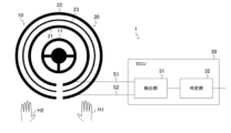
- FIG. 1 is a diagram showing a simplified configuration example of a contact determination device 1.
- the contact determination device 1 is a device installed in a vehicle, and is a device that determines whether the hands H1, H2 of the vehicle driver are in contact with the steering wheel 10.
- the steering wheel 10 is installed in front of a seat (driver's seat) where a driver is seated.
- the contact determination device 1 includes a sheet-shaped electrode section 20 installed on the steering wheel 10 and an ECU (Electronic Control Unit) 30.
- the electrode section 20 functions as a so-called touch sensor, and is a sheet-shaped electrode section configured by laminating a first electrode 21 and a second electrode 22 with an insulator 23 in between.
- the first electrode 21 can also be called an active shield electrode
- the second electrode 22 can also be called a sensor electrode.
- the touch sensor realized by the electrode section 20 is, for example, a capacitive touch sensor.
- the steering wheel 10 is an operating member that includes a metal core 11 that forms the skeleton of the steering wheel 10, and is used when a driver driving the vehicle steers the vehicle. Further, the substantially annular grip portion of the steering wheel 10 is a portion that is held by a driver who drives the vehicle, and the core metal 11 is covered with a base body. Note that an insulating material is used as the base. For example, a resin material such as urethane is used as the base.
- the first electrode 21 is a sheet-shaped electrode that is electrically connected to the ECU 30 via the signal line S1.
- the second electrode 22 is a sheet-shaped electrode electrically connected to the ECU 30 via the signal line S2.
- the insulator 23 is an elastic sheet-like insulator, for example, an insulating sheet.
- an electrode portion 20 is attached to the outer peripheral portion of the base that constitutes the gripping portion of the steering wheel 10 so as to cover the base in the circumferential direction of the steering wheel 10 .
- a first electrode 21 is arranged on the inner circumferential side of the steering wheel 10
- a second electrode 22 is arranged on the outer circumferential side of the steering wheel 10.
- FIG. 1 shows an example in which the electrode portion 20 is provided in all portions of the steering wheel 10 in the circumferential direction, the electrode portion 20 may be provided in a portion of the circumferential direction of the steering wheel 10.
- an exterior part serving as a contact part which is a part that the driver holds with his hand, is attached to the outer peripheral part of the electrode part 20.
- This exterior part is preferably made of insulating leather, resin, or the like. In this manner, the electrode portion 20 is disposed between the base and the exterior portion at the grip portion of the steering wheel 10. That is, the electrode portion 20 is covered with the exterior portion.
- the ECU 30 controls each section based on various programs stored in a storage section (not shown), and includes a detection section 31 and a determination section 32.
- the ECU 30 is realized, for example, by a processing device such as a CPU (Central Processing Unit).
- the storage unit stores various information (for example, a control program, each detected value) necessary for the ECU 30 to perform various processes.
- ROM Read Only Memory
- RAM Random Access Memory
- HDD Hard Disk Drive
- SSD Solid State Drive
- the detection unit 31 is connected to the first electrode 21 via the signal line S1 and to the second electrode 22 via the signal line S2, and detects the capacitance and impedance generated in the first electrode 21 and the second electrode 22.
- the detection result is output to the determination unit 32.
- the detection unit 31 supplies an AC signal to the electrode unit 20 and detects the capacitance and impedance generated in the first electrode 21 and the second electrode 22 based on a response signal acquired in response to the AC current. do.
- known measuring methods can be used to measure capacitance and impedance.
- impedance can be detected based on the signal ratio (current/voltage) obtained by applying an AC signal to the electrode section 20 and measuring voltage and current simultaneously.
- an absolute self-capacitance type electrostatic IC can be employed as the detection unit 31, which is capable of simultaneously measuring sensor inputs of multiple zones and has a characteristic that the sensor drive waveform is a sine wave.
- This electrostatic IC drives the shield electrode (first electrode 21) and compares the driving waveform with the input waveform from the sensor electrode (second electrode 22). Then, the electrostatic IC digitally converts the compared difference waveform, demodulates and integrates the sine component and cosine component of the drive frequency, and calculates a detected value. Among these detected values, impedance is calculated based on the calculation result of the sine component, and capacitance is calculated based on the calculation result of the cosine component. In this way, the detection section 31 can output a sine wave to the electrode section 20 and detect the capacitance and impedance based on the difference in phase and amplitude between the sine wave and the response wave.
- the detection unit 31 can detect the capacitance generated in the second electrode 22 in response to the driver's contact with the steering wheel 10 using a capacitance method such as a self-capacitance method or a mutual capacitance method.
- FIG. 2 is a diagram showing an example where a part of the second electrode 22 is cut off.
- FIG. 2A shows a simplified position 25 where the second electrode 22 is partially cut off in the steering wheel 10. Note that in FIG. 2(A), a part of the configuration of the contact determination device 1 shown in FIG. 1 is omitted. Further, in order to facilitate explanation, FIG. 2(B) schematically shows the relationship between the first electrode 21, the second electrode 22, and the ECU 30.
- the process of attaching the electrode section 20 to the steering wheel 10 will be explained.
- the sheet-like first electrode 21 and second electrode 22 an example is shown in which a conductive cloth in which a metal plating treatment is applied to a cloth woven into a mesh structure is used.
- this conductive cloth has flexibility and extensibility, it is also assumed that the metal plating may peel off or the conductive cloth may easily spread.
- the sheet-shaped electrode part 20 when attaching the sheet-shaped electrode part 20 to the steering wheel 10, it is necessary to wrap the sheet-shaped electrode part 20 around the steering wheel 10 using a jig such as a perforation rod.
- a jig such as a perforation rod.
- the sheet-shaped electrode portion 20 is wound around a complicated surface.
- the conductive cloth may stretch, or that the conductive cloth may be further damaged by excessive pushing with the perforation rod in a state where the conductive cloth has stretched.
- the electrodes of the conductive cloth have defects such as defects. As described above, if the electrode has a defect such as a defect or is damaged during the installation process, a part of the electrode will be cut off.
- FIG. 2(A) schematically shows a case where the sheet-shaped first electrode 21 and second electrode 22 are arranged in parallel. Such cut portions are sometimes referred to as plating cracks.
- both the capacitance and resistance between the first electrode 21 and the second electrode 22 may have normal values. many.
- the area of the second electrode 22 after the cut portion shown at position 25 will be lost.
- the capacitance also decreases accordingly. Note that in FIG. 2(B), the area range of the second electrode 22 after the cut portion indicated by position 25 is indicated by R1. In this way, when the cut portion of the second electrode 22 is electrically disconnected, the resistance value at the cut portion increases, but the capacitance decreases.
- FIG. 3 is a diagram showing an example of contact determination as a comparative example. Specifically, an example of the relationship between the capacitance generated in the electrode section 20 and the determination value ⁇ AD used when determining whether the driver has touched the steering wheel 10 will be shown.
- FIG. 3(A) shows an example when the electrode section 20 is in a normal state, that is, there is no abnormality in the electrode section 20, and FIG. 3(B) shows an example when the electrode section 20 is in a disconnected state. , that is, an example in which there is an abnormality in the electrode section 20 is shown. Note that, similarly to the example shown in FIG. 2(B), FIG. 3(B) shows an example where position 25 is the cut portion.
- a state in which the second electrode 22 is disconnected will be referred to as an abnormal state, but the same applies to a case in which the first electrode 21 is disconnected or an abnormal state occurs due to other reasons. Applicable.
- the case will be described as a case where the electrode section 20 becomes abnormal, but the case is not limited to this, and the case where the electrode section 20 becomes abnormal is referred to as the case where the electrode section 20 becomes defective. This may also be referred to as a case where the electrode section 20 has failed.
- the determination value ⁇ AD used in the comparative example will be explained.
- the determination value ⁇ AD can be determined using Equation 1 below.
- Crg is the capacitance generated between the driver's hand and the second electrode 22 when the driver's hand approaches the second electrode 22.
- Crs is the capacitance between the first electrode 21 and the second electrode 22. That is, Crs means the capacitance originally held by the electrode section 20.
- the difference value of ⁇ AD shown in Equation 1 may be used as the determination value.
- ⁇ AD Crg/(Crs+Crg)...Formula 1
- the capacitance Crs between the first electrode 21 and the second electrode 22 is normally a fixed value.
- the value of the capacitance Crg changes depending on the driver's contact state with the steering wheel 10. Specifically, when the driver's hand is not in contact with the steering wheel 10, the capacitance Crg is 0 or a value close to 0.
- the value of the capacitance Crg increases depending on the degree of contact. That is, when the driver grips the steering wheel 10, the capacitance Crg is added and the determination value ⁇ AD increases. Furthermore, if the driver continues to hold the steering wheel 10, the determination value ⁇ AD remains high. On the other hand, when the driver releases the steering wheel 10, the determination value ⁇ AD rapidly decreases.
- the capacitance Crs1 between the first electrode 21 and the second electrode 22 when the electrode section 20 is in a normal state is higher than that when the electrode section 20 is in a disconnected state.
- the capacitance Crs2 between the first electrode 21 and the second electrode 22 decreases.
- the contact determination device 1 may make an erroneous determination. Therefore, in this embodiment, an example will be shown in which contact determination is performed using a decrease in the capacitance component and an increase in the resistance component when the electrode section 20 is in a disconnected state. Thereby, for example, it is possible to implement logic that does not determine contact when the capacitance component decreases and the resistance component increases, which is clearly caused by disconnection of the electrode.
- FIG. 4 is a diagram illustrating an example of a determination process for determining contact determination based on the capacitance ⁇ Ca and impedance ⁇ Zb generated in the electrode section 20.
- the horizontal axis shown in FIG. 4 shows capacitance ⁇ Ca, and the vertical axis shown in FIG. 4 shows impedance ⁇ Zb.
- impedance means resistance when alternating current is passed, and is also referred to as alternating current resistance.
- capacitance ⁇ Ca shown in FIG. 4 means the capacitance generated in the second electrode 22 in response to the driver's contact with the steering wheel 10.
- impedance ⁇ Zb means the impedance between the first electrode 21 and the second electrode 22.
- the capacitance Crg increases depending on the driver's contact state with the steering wheel 10.
- the resistance between the first electrode 21 and the second electrode 22 does not change due to contact with the driver, the variation in impedance ⁇ Zb is small. Therefore, when the electrode section 20 is in a normal state, even when the driver grips the steering wheel 10, the slope of the capacitance ⁇ Ca and the impedance ⁇ Zb ( ⁇ Zb/ ⁇ Ca) is a low value, for example, 1/8 to 1/8. It will be about 15. That is, when the electrode section 20 is in a normal state, the slopes ( ⁇ Zb/ ⁇ Ca) of the capacitance ⁇ Ca and the impedance ⁇ Zb are small even when the driver grips the steering wheel 10.
- the electrode section 20 when the electrode section 20 is in an abnormal state, for example, when the second electrode 22 is in a disconnected state, when the driver grips the steering wheel 10, the capacitance increases depending on the driver's contact state on the steering wheel 10. Crg increases.
- the resistance between the first electrode 21 and the second electrode 22 is determined by the resistance between the first electrode 21 and the second electrode 22, as shown in FIGS. 2 and 3. Change occurs. That is, when the second electrode 22 is cut off due to contact with the driver, the resistance value changes to a small value depending on the contact state of the driver. Therefore, fluctuations in impedance ⁇ Zb become large. That is, since the impedance ⁇ Zb greatly decreases depending on the contact state of the driver, the fluctuation also increases.
- the absolute value of the slope ( ⁇ Zb/ ⁇ Ca) of the capacitance ⁇ Ca and the impedance ⁇ Zb is a high value, for example, 1 to 2 or more. becomes. That is, when the electrode section 20 is in an abnormal state, the slope ( ⁇ Zb/ ⁇ Ca) of the capacitance ⁇ Ca and the impedance ⁇ Zb increases when the driver grips the steering wheel 10. That is, the amount of change in impedance ⁇ Zb varies greatly with respect to the amount of change in capacitance ⁇ Ca.
- the resistance between the first electrode 21 and the second electrode 22 will not change due to contact with the driver, but the resistance will change. The value will be small. Therefore, when the second electrode 22 is in the disconnected state regardless of whether or not it is in contact with the driver, the value of the impedance ⁇ Zb becomes small.
- contact determination is performed using the relationship between capacitance ⁇ Ca and impedance ⁇ Zb. Specifically, if the capacitance ⁇ Ca is less than or equal to the contact threshold TH11 indicated by the straight line SL2, it is determined that there is no contact. That is, if the intersection of the capacitance ⁇ Ca and the impedance ⁇ Zb exists in the non-contact area NCA1, it is determined that there is no contact.
- the capacitance ⁇ Ca exceeds the contact threshold TH11 indicated by the straight line SL2, it is determined that there is a contact.
- the capacitance ⁇ Ca exceeds the contact threshold TH11 (straight line SL2), if the impedance ⁇ Zb is less than or equal to the stepped broken line SL1, the electrode section 20 is in an abnormal state, for example, the second electrode 22 Since it is assumed that the device is in a disconnected state, it is determined to be abnormal.
- the contact threshold TH11 is a contact determination threshold used when determining the driver's contact with the steering wheel 10.
- the contact threshold value TH11 can be set as appropriate based on experimental data and the like.
- the contact threshold TH11 may be a fixed value, or may be variable depending on the driver, the internal environment of the vehicle, the environment around the vehicle, such as temperature, humidity, etc.
- the stair-shaped polygonal line SL1 is an abnormality determination threshold value used when determining an abnormality in the electrode section 20.
- the abnormality determination threshold is set to TH21.
- the capacitance ⁇ Ca is greater than TH12 and is in the range of TH13 or less
- the abnormality determination threshold is set to TH22.
- TH23 to TH25 are similarly set as abnormality determination thresholds according to the range of capacitance ⁇ Ca (TH13 to TH15). In this way, values TH21 to TH25 that decrease as the capacitance ⁇ Ca increases can be set as the abnormality determination thresholds.
- FIG. 4 shows an example in which abnormality determination thresholds TH21 to TH25 are set that decrease stepwise, other thresholds that decrease in accordance with an increase in capacitance ⁇ Ca may be set as the abnormality determination thresholds.
- the value TH expressed by the following equation 3 can be set as the abnormality determination threshold.
- DC1 and ⁇ 1 are diagnostic coefficients, which can be set as appropriate based on experimental data and the like.
- TH ⁇ Ca ⁇ DC1+ ⁇ 1...Formula 3
- FIG. 4 shows an example in which contact is determined using the latest relationship between capacitance ⁇ Ca and impedance ⁇ Zb.
- FIG. 4 shows an example in which contact is determined using the latest relationship between capacitance ⁇ Ca and impedance ⁇ Zb.
- FIG. 5 is a flowchart illustrating an example of contact determination processing in the contact determination device 1. Further, this contact determination process is executed by the ECU 30 based on a program stored in a storage unit (not shown). Further, this contact determination process is always executed every control cycle. Note that the determination unit 32 retains the capacitance and impedance detected by the detection unit 31 a predetermined number of times. This predetermined number of times is assumed to be a value of N or more.
- N is a value appropriately set based on experimental data and the like.
- step S501 the detection unit 31 detects the capacitance ⁇ Ca and impedance ⁇ Zb of the electrode unit 20.
- step S502 the determination unit 32 obtains N times of capacitance from among the capacitances detected by the detection unit 31.
- the capacitances N times are N values from the capacitance acquired last to the capacitance acquired N times before.
- step S503 the determination unit 32 calculates the moving average value ⁇ Ca1 of the N times of capacitance acquired in step S501.
- the moving average value ⁇ Ca1 means the average value of N times of capacitance.
- FIG. 5 shows an example using the moving average value ⁇ Ca1, as described above, one capacitance may be used, and other capacitances calculated using one or more capacitances may be used. Values may also be used.
- step S504 the determination unit 32 determines whether the moving average value ⁇ Ca1 calculated in step S502 is larger than the contact threshold TH11 (see FIG. 4). If the moving average value ⁇ Ca1 is less than or equal to the contact threshold TH11, the process advances to step S505. On the other hand, if the moving average value ⁇ Ca1 is larger than the contact threshold TH11, the process advances to step S506.
- step S505 the determination unit 32 determines that the driver's hand is not in contact with the steering wheel 10. That is, since the moving average value ⁇ Ca1 exists in the non-contact area NCA1 (see FIG. 4), it is determined that there is no contact.
- step S506 the determination unit 32 obtains N times of impedances from among the impedances detected by the detection unit 31.
- the impedances N times are N values from the impedance acquired last to the impedance acquired N times before.
- step S507 the determination unit 32 calculates a moving average value ⁇ Zb1 of the impedances acquired N times in step S505.
- the moving average value ⁇ Zb1 means the average value of N times of impedance.
- FIG. 5 shows an example using the moving average value ⁇ Zb1, as described above, one impedance may be used, or other values calculated using one or more impedances may be used. Good too.
- step S508 the determination unit 32 determines whether the moving average value ⁇ Zb1 calculated in step S506 satisfies Equation 4 described above. If the moving average value ⁇ Zb1 satisfies Equation 4 described above, the process advances to step S509. On the other hand, if the moving average value ⁇ Zb1 does not satisfy Equation 4 described above, the process advances to step S510.
- step S509 the determination unit 32 determines that the driver's hand is in contact with the steering wheel 10. That is, since the intersection of the moving average value ⁇ Zb1 and the moving average value ⁇ Ca1 exists in the contact area CA1 (see FIG. 4), it is determined that there is a contact.
- step S510 the determination unit 32 determines that the contact determination device 1 is abnormal. That is, since the intersection of the moving average value ⁇ Zb1 and the moving average value ⁇ Ca1 exists in the abnormal area AA1 (see FIG. 4), it is determined to be abnormal.
- the determination unit 32 outputs the determination result for use in automatic driving or outputting a warning. For example, if it is determined that the vehicle is being driven without hands in a vehicle that is at a predetermined automatic driving level, a warning is output. Further, for example, an alarm may also be output when it is determined that the electrode section 20 is abnormal.
- the electrode An example will be shown in which it is determined that the unit 20 is abnormal. However, if the moving average value ⁇ Ca1 exceeds the contact threshold TH11, and the number of times that the moving average value ⁇ Zb1 becomes less than or equal to the abnormality determination threshold (the abnormality determination threshold TH shown in equation 4) is equal to or greater than a predetermined number (2 or more) Alternatively, it may be determined that the electrode section 20 is abnormal. As a result, even if an abnormal value is detected due to variations, radio wave noise, etc., the abnormal value can be eliminated and the accuracy of contact determination can be improved.
- the abnormal state of the electrode section 20 is determined more reliably by using the capacitance ⁇ Ca and impedance ⁇ Zb of the electrode section 20. be able to. Thereby, for example, it is possible to prevent an inappropriate contact determination from being impossible due to failure of an electrode. Further, by simply changing the logic of the software, the accuracy of contact determination can be improved, and the robustness can be improved.
- a sheet-like electrode section 20 formed by laminating a first electrode 21 and a second electrode 22 with an insulator 23 in between covers the outer circumference of the steering wheel 10.
- This contact determination method includes a detection step (step S501) of detecting capacitance ⁇ Ca and impedance ⁇ Zb generated in the electrode section 20, and a steering control based on the capacitance ⁇ Ca and impedance ⁇ Zb detected in the detection step.
- step S502 to S510 It includes determination steps (steps S502 to S510) for determining whether the driver's hand has touched the wheel 10 and whether or not the electrode section 20 is abnormal.
- the capacitance ⁇ Ca exceeds the contact threshold TH11 (an example of the first threshold)
- the impedance ⁇ Zb exceeds the abnormality determination threshold (broken line SL1 (see FIG. 4), equation 4).
- the abnormality determination threshold value TH an example of a second threshold value
- the abnormal state of the electrode section 20 can be determined more reliably by using the capacitance ⁇ Ca and the impedance ⁇ Zb of the electrode section 20. .
- a fixed value is set as the contact threshold TH11 (an example of the first threshold), and the abnormality determination threshold (broken line SL1 (see FIG. 4), the abnormality determination threshold TH (shown in equation 4)
- the second threshold value a variable value that decreases as the capacitance increases is set.
- an abnormal state of the electrode section 20 can be determined more reliably by setting an appropriate threshold value.
- the abnormality determination threshold TH (an example of the second threshold) shown in Equation 4 is a value ( ⁇ Ca ⁇ DC1+ ⁇ 1).
- the abnormal state of the electrode section 20 can be determined more reliably by setting the threshold value using specific parameters.
- the moving average value ⁇ Ca1 of a predetermined number of capacitances detected within a predetermined time is the contact threshold TH11 (first threshold
- the moving average value ⁇ Zb1 of a predetermined number of impedances detected within a predetermined time exceeds the abnormality determination threshold (broken line SL1 (see FIG. 4), the abnormality determination threshold TH (second threshold) shown in equation 4). For example, if the number of times the electrode part 20 has fallen below () is equal to or greater than a predetermined number, it is determined that the electrode section 20 is abnormal.
- the moving average value ⁇ Ca1 of a predetermined number of capacitances detected within a predetermined time is set to a contact threshold TH11 (an example of a first threshold). ), it is determined that the driver's hand is not in contact with the steering wheel 10.
- the moving average value ⁇ Ca1 of capacitance is larger than the contact threshold TH11, and the moving average value ⁇ Zb1 of a predetermined number of impedances detected within a predetermined time is an abnormality determination threshold (broken line If SL1 (see FIG.
- the electrode unit 20 is configured such that the second electrode 22 is arranged on the outside of the steering wheel 10 and the first electrode 21 is arranged on the inside of the steering wheel 10. .
- the detection step (step S501) the capacitance ⁇ Ca generated in the second electrode 22 and the capacitance ⁇ Ca generated in the first electrode 21 and the second electrode 22 is detected.
- a sheet-like electrode section 20 formed by laminating a first electrode 21 and a second electrode 22 with an insulator 23 in between is provided so as to cover the outer periphery of the steering wheel 10.
- the contact determination device 1 includes a detection unit 31 that detects capacitance ⁇ Ca and impedance ⁇ Zb generated in the electrode unit 20, and a detection unit 31 that detects the capacitance ⁇ Ca and impedance ⁇ Zb that are generated in the electrode unit 20. It includes a determination unit 32 that determines whether the driver's hand has touched it and whether or not the electrode unit 20 is abnormal.
- the determination unit 32 determines that the capacitance ⁇ Ca exceeds the contact threshold TH11 (an example of the first threshold), and the impedance ⁇ Zb exceeds the abnormality determination threshold (broken line SL1 (see FIG. 4), the abnormality determination threshold TH (first threshold) shown in Equation 4. (Example of two threshold values)), it is determined that the electrode section 20 is abnormal.
- the abnormal state of the electrode section 20 can be determined more reliably by using the capacitance ⁇ Ca and the impedance ⁇ Zb of the electrode section 20. .
- each processing procedure shown in this embodiment is an example for realizing this embodiment, and the order of a part of each processing procedure may be changed to the extent that this embodiment can be realized. Often, a part of each processing procedure may be omitted or other processing steps may be added.
- each process shown in this embodiment is executed based on a program for causing a computer to execute each process procedure. Therefore, this embodiment can also be understood as an embodiment of a program that implements the function of executing each of these processes, and a recording medium that stores the program. For example, in an update process for adding a new function to the contact determination device, the program can be stored in the storage device of the contact determination device. Thereby, it becomes possible to cause the updated contact determination device to perform each process shown in this embodiment.
Landscapes
- Engineering & Computer Science (AREA)
- Chemical & Material Sciences (AREA)
- Combustion & Propulsion (AREA)
- Transportation (AREA)
- Mechanical Engineering (AREA)
- Steering Controls (AREA)
Abstract
絶縁体を挟んで第1電極及び第2電極を積層して構成されるシート状の電極部が、ステアリングホイールの外周部を覆うように設けられ、電極部から検出される電気信号に基づいて、ドライバのステアリングホイールへの接触判定を行う接触判定方法である。この接触判定方法は、電極部に生じる静電容量及びインピーダンスを検出する検出ステップと、検出ステップで検出された静電容量と、インピーダンスとに基づいて、ステアリングホイールにドライバの手が接触したか否かと、電極部が異常であるか否かとを判定する判定ステップと、を備える。判定ステップでは、静電容量が第1閾値を超え、かつ、インピーダンスが第2閾値を下回った場合には、電極部が異常であると判定する。
Description
本発明は、ステアリングホイールへのドライバの接触を判定する接触判定方法及び接触判定装置に関する。
WO2021/095478には、ステアリングホイールの外周部に、2つの電極が絶縁体を介して重ねて設けられ、ステアリングホイールへのドライバの接触を判定する技術が開示されている。
一般に、ステアリングホイールは平面ではなく複雑な面となることが多い。このため、シート状の電極及び絶縁体をステアリングホイールに取り付ける作業時には、ステアリングホイールの複雑な面に応じて治具等を使用してシート状の電極及び絶縁体を取り付けていく必要がある。しかし、電極に失陥の不良があったり、取付作業時に電極を傷つけたりした場合には、電極の一部が切断された状態となってしまうおそれがある。このような状態では、電極が異常な状態となり適切な接触判定を行うことができない。
本発明は、ステアリングホイールへのドライバの接触を判定する場合に電極部の異常状態をより確実に判定することを目的とする。
本発明の一態様は、絶縁体を挟んで第1電極及び第2電極を積層して構成されるシート状の電極部が、ステアリングホイールの外周部を覆うように設けられ、電極部から検出される電気信号に基づいて、ドライバのステアリングホイールへの接触判定を行う接触判定方法である。この接触判定方法は、電極部に生じる静電容量及びインピーダンスを検出する検出ステップと、検出ステップで検出された静電容量と、インピーダンスとに基づいて、ステアリングホイールにドライバの手が接触したか否かと、電極部が異常であるか否かとを判定する判定ステップと、を備える。判定ステップでは、静電容量が第1閾値を超え、かつ、インピーダンスが第2閾値を下回った場合には、電極部が異常であると判定する。
以下、添付図面を参照しながら本発明の実施形態について説明する。
[接触判定装置の構成例]
図1は、接触判定装置1の構成例を簡略化して示す図である。接触判定装置1は、車両に設置される機器であり、車両のドライバの手H1、H2がステアリングホイール10に接触しているか否かを判定する装置である。ステアリングホイール10は、ドライバが着座する座席(運転席)の前側に設置されている。
図1は、接触判定装置1の構成例を簡略化して示す図である。接触判定装置1は、車両に設置される機器であり、車両のドライバの手H1、H2がステアリングホイール10に接触しているか否かを判定する装置である。ステアリングホイール10は、ドライバが着座する座席(運転席)の前側に設置されている。
接触判定装置1は、ステアリングホイール10に設置されるシート状の電極部20と、ECU(Electronic Control Unit)30とを備える。電極部20は、いわゆるタッチセンサとして機能するものであり、絶縁体23を挟んで第1電極21及び第2電極22を積層して構成されるシート状の電極部である。なお、第1電極21は、アクティブシールド電極とも称し、第2電極22は、センサ電極と称することもできる。また、電極部20により実現されるタッチセンサは、例えば静電容量方式のタッチセンサである。
ここで、ステアリングホイール10は、ステアリングホイール10の骨格を形成する金属製の芯金11を備える操作部材であって、車両を運転するドライバが車両を操舵する際に使用される。また、ステアリングホイール10の略円環状の把持部は、車両を運転するドライバが手で握る部分であり、芯金11の周りが基体により被覆されている。なお、基体として、絶縁材料が用いられる。例えば、基体としてウレタン等の樹脂材料が用いられる。
第1電極21は、信号線S1を介してECU30に電気的に接続されるシート状の電極である。また、第2電極22は、信号線S2を介してECU30に電気的に接続されるシート状の電極である。また、絶縁体23は、弾性を有するシート状の絶縁体、例えば絶縁性シートである。
また、ステアリングホイール10の把持部を構成する基体の外周部には、ステアリングホイール10の周方向において基体を覆うように電極部20が装着される。また、ステアリングホイール10の内周側に第1電極21が配置され、ステアリングホイール10の外周側に第2電極22が配置される。なお、図1では、ステアリングホイール10の周方向の全ての部分に電極部20を設ける例を示すが、ステアリングホイール10の周方向のうちの一部に電極部20を設けてもよい。また、電極部20の外周部には、ドライバが手で握る部分である接触部としての外装部が装着される。この外装部は、絶縁性を有する皮革製や樹脂製等とすることが好ましい。このように、ステアリングホイール10の把持部において、基体と外装部との間に電極部20が配置される。すなわち、電極部20は、外装部により被覆される。
ECU30は、記憶部(図示省略)に記憶されている各種プログラムに基づいて各部を制御するものであり、検出部31と、判定部32とを備える。ECU30は、例えば、CPU(Central Processing Unit)等の処理装置により実現される。また、記憶部にはECU30が各種処理を行うために必要となる各種情報(例えば、制御プログラム、各検出値)が記憶される。この記憶部として、例えば、ROM(Read Only Memory)、RAM(Random Access Memory)、HDD(Hard Disk Drive)、SSD(Solid State Drive)、または、これらの組み合わせを用いることができる。
検出部31は、信号線S1を介して第1電極21と接続され、信号線S2を介して第2電極22と接続され、第1電極21及び第2電極22に生じる静電容量及びインピーダンスを検出するものであり、検出結果を判定部32に出力する。例えば、検出部31は、電極部20に交流信号を供給し、この交流電流に応じて取得された応答信号に基づいて、第1電極21及び第2電極22に生じる静電容量及びインピーダンスを検出する。なお、静電容量及びインピーダンスの測定方法については、公知の測定方法を用いることができる。例えば、電極部20に交流信号を印加し、電圧と電流を同時に測定した測定結果により取得された信号の比(電流/電圧)に基づいてインピーダンスを検出可能である。例えば、複数ゾーンのセンサ入力の同時測定が可能でセンサの駆動波形が正弦波であるという特徴を有する、絶対自己容量方式の静電ICを検出部31として採用することができる。この静電ICは、シールド電極(第1電極21)を駆動し、その駆動波形とセンサ電極(第2電極22)からの入力波形とを比較をする。そして、静電ICは、その比較した差分波形をデジタル変換し、駆動周波数のsin成分及びcos成分で復調及び積分して検出値を算出する。この検出値のうち、sin成分の算出結果に基づいてインピーダンスが算出され、cos成分の算出結果に基づいて静電容量が算出される。このように、検出部31は、電極部20に正弦波を出力し、その正弦波と応答波との位相及び振幅の差分に基づいて静電容量及びインピーダンスを検出することができる。
また、例えば、ドライバの手がステアリングホイール10に接触または近接することで、ドライバの手が第2電極22に近接し、第2電極22の静電容量Crgが変化する。この第2電極22の静電容量Crgは、自己容量方式や相互容量方式等の静電容量方式により検出することが可能である。すなわち、検出部31は、自己容量方式や相互容量方式等の静電容量方式により、ステアリングホイール10へのドライバの接触に応じて第2電極22に生じる静電容量を検出することができる。
[電極部の故障発生例]
図2は、第2電極22の一部が切断された場合の例を示す図である。図2(A)には、ステアリングホイール10において第2電極22の一部が切断された位置25を簡略化して示す。なお、図2(A)では、図1に示す接触判定装置1の構成のうちの一部を省略する。また、図2(B)には、説明を容易にするため、第1電極21と、第2電極22と、ECU30との関係を模式的に示す。
図2は、第2電極22の一部が切断された場合の例を示す図である。図2(A)には、ステアリングホイール10において第2電極22の一部が切断された位置25を簡略化して示す。なお、図2(A)では、図1に示す接触判定装置1の構成のうちの一部を省略する。また、図2(B)には、説明を容易にするため、第1電極21と、第2電極22と、ECU30との関係を模式的に示す。
ここで、電極部20をステアリングホイール10に取り付ける工程について説明する。ここでは、シート状の第1電極21及び第2電極22として、メッシュ構造に織られた布に金属メッキ処理が施された導電布を用いる例を示す。この導電布は、柔軟性、伸張性を有するが、金属メッキが剥がれたり、導電布の目が広がりやすくなったりすることも想定される。
例えば、ステアリングホイール10にシート状の電極部20を取り付ける作業時には、目打ち棒等の治具を使用してステアリングホイール10にシート状の電極部20を巻いていく必要がある。しかし、ステアリングホイール10には、平らな面がないため、シート状の電極部20を複雑な面に巻いていく。この取付作業時に、導電布に伸びが入ったり、導電布に伸びが入った状態で目打ち棒による過度の押し込み作業でさらに導電布にダメージを与えたりすることも想定される。また、導電布の電極に失陥等の不良があることも想定される。このように、電極に失陥等の不良があったり、取付作業時に電極を傷つけたりした場合には、電極の一部が切断された状態となってしまう。このような状態で、シート状の電極部20に外装部を巻き付ける革巻き作業が行われた後に、ドライバにより外装部が握られると導電布が伸縮し、電極の切断部分がさらに広がることも想定される。このように、電極の切断部分がさらに広がると、その切断部分の抵抗値が上昇することになる。
例えば、図2(A)に示すように、ステアリングホイール10における位置25で、第2電極22の一部が切断された場合を想定する。なお、図2(B)には、説明を容易にするため、シート状の第1電極21及び第2電極22を平行にした場合を模式的に示す。このような切断部分をメッキクラックと称することもある。
例えば、図2(A)に示す位置25で第2電極22の一部が切断された状態でも、この切断部分の電極同士が接触している状態では、電気的に接続状態となる。この接続状態は、疑似接触と称することもできる。このように、位置25の切断部分が、電気的に接続状態となっている場合には、第1電極21及び第2電極22間の静電容量及び抵抗の双方が正常な値となることが多い。
しかし、ステアリングホイール10において、ドライバの手により外装部を介して切断部分が握られた場合、荷重により微小変形が発生し、切断部分が微小に離れることになる。この場合には、切断部分の間の導通抵抗が大きくなり、電流が流れにくくなるため、第2電極22における切断部分の抵抗が異常に増加する。
また、切断部分の離れ量が大きくなりすぎると、切断部分が電気的にも完全に断線するため、位置25で示す切断部分以降の第2電極22の面積が失われるため、その面積の減少に応じて静電容量も低下する。なお、図2(B)では、位置25で示す切断部分以降の第2電極22の面積の範囲をR1で示す。このように、第2電極22の切断部分が電気的にも断線すると、その切断部分での抵抗値は上昇するが、静電容量は低下することになる。
[比較例としての接触判定例]
図3は、比較例としての接触判定例を示す図である。具体的には、電極部20に生じる静電容量と、ステアリングホイール10へのドライバの接触を判定する際に用いられる判定値ΔADとの関係例を示す。
図3は、比較例としての接触判定例を示す図である。具体的には、電極部20に生じる静電容量と、ステアリングホイール10へのドライバの接触を判定する際に用いられる判定値ΔADとの関係例を示す。
図3(A)には、電極部20が正常状態の場合、すなわち電極部20に異常がない場合の例を示し、図3(B)には、電極部20が断線状態となっている場合、すなわち電極部20に異常がある場合の例を示す。なお、図3(B)では、図2(B)に示す例と同様に、位置25が切断部分となっている場合の例を示す。
なお、本実施形態では、第2電極22が切断された状態を異常状態と称して説明するが、第1電極21が切断された場合や他の理由により異常状態となった場合についても同様に適用可能である。
また、本実施形態では、電極部20が異常となった場合と称して説明するが、これに限定されず、電極部20が異常となった場合を、電極部20が失陥となった場合、電極部20が故障となった場合等と称してもよい。
最初に、比較例で用いられる判定値ΔADについて説明する。判定値ΔADについては、以下の式1により求めることができる。なお、Crgは、ドライバの手が第2電極22に近接する際に手及び第2電極22間に発生する静電容量である。また、Crsは、第1電極21及び第2電極22間の静電容量である。すなわち、Crsは、電極部20がもともと保持している静電容量を意味する。なお、判定値ΔADの代わりに、式1に示すΔADの差分値を判定値として用いてもよい。
ΔAD=Crg/(Crs+Crg) …式1
ΔAD=Crg/(Crs+Crg) …式1
第1電極21及び第2電極22間の静電容量Crsについては、以下の式2により求めることができる。なお、εrsは、第1電極21及び第2電極22間の誘電率である。また、drsは、第1電極21及び第2電極22間の距離である。また、Srsは、第2電極22の面積である。
Crs=εrs(Srs/drs) …式2
Crs=εrs(Srs/drs) …式2
なお、電極部20において、芯金11及び第2電極22間の静電容量Crgl、芯金11及び第1電極21間の静電容量Csgも生じるが、ここでの説明を省略する。
第1電極21及び第2電極22間の静電容量Crsは、通常時には固定値となる。これに対して、静電容量Crgは、ステアリングホイール10におけるドライバの接触状態に応じて値が変化する。具体的には、ステアリングホイール10にドライバの手が接触していない状態では、静電容量Crgは0または0に近い値となる。一方、ステアリングホイール10にドライバの手が接触している状態では、静電容量Crgは、接触の程度に応じて値が増加する。すなわち、ステアリングホイール10をドライバが握ると、静電容量Crgが付加され、判定値ΔADが増加する。また、ステアリングホイール10をドライバが握っている状態が継続している場合には、判定値ΔADが高い値を維持している状態となる。一方、ステアリングホイール10をドライバが離した場合には、判定値ΔADが急激に減少する。
この比較例では、判定値ΔADが接触閾値TH1を超えた場合には、接触と判定する。例えば、図3(A)の下側のグラフで示す曲線L1のように、判定値ΔADが接触閾値TH1を超えた状態では、接触と判定される。
ここで、電極部20が正常状態の場合(図3(A)参照)と、電極部20が断線状態の場合(図3(B)参照)との第1電極21及び第2電極22間の静電容量及び抵抗について説明する。
電極部20が正常状態の場合(図3(A)参照)と、電極部20が断線状態の場合(図3(B)参照)とを比較すると、電極部20が断線状態の場合には、位置25で示す切断部分以降の第2電極22の面積が失われている。このため、第1電極21及び第2電極22間の電気が流れにくくなり、電極部20が正常状態の場合の第1電極21及び第2電極22間の抵抗値Rs1よりも、電極部20が断線状態の場合の第1電極21及び第2電極22間の抵抗値Rs2が大きくなる。
また、第2電極22の面積が失われているため、電極部20が正常状態の場合の第1電極21及び第2電極22間の静電容量Crs1よりも、電極部20が断線状態の場合の第1電極21及び第2電極22間の静電容量Crs2が低下する。
このように、第2電極22の面積が減少すると、第1電極21及び第2電極22間の静電容量Crs2が低下するため、式1の分母も大きくなり、判定値ΔADの値が大きくなる。また、ドライバがステアリングホイール10から手を離した後に、電極部20の断線状態が継続すると、判定値ΔADの値が大きい状態が継続され、判定値ΔADが接触閾値TH1を超えた状態となってしまうおそれがある。例えば、図3(B)の下側のグラフで示す曲線L2のように、ドライバがステアリングホイール10から手を離したにもかかわらず、判定値ΔADが接触閾値TH1を超えた状態が維持されてしまうおそれがある。この場合には、接触判定装置1が誤判定をしてしまうおそれがある。そこで、本実施形態では、電極部20が断線状態の場合の静電容量成分の減少と抵抗成分の増加とを利用して接触判定を実行する例を示す。これにより、例えば、明らかに電極の切断を原因とする静電容量成分の減少及び抵抗成分の増加のときに、接触と判定しないロジックを実装することができる。
[静電容量及びインピーダンスに基づく接触判定例]
図4は、電極部20に生じる静電容量ΔCa及びインピーダンスΔZbに基づいて接触判定を判定する判定処理の一例を示す図である。図4に示す横軸は、静電容量ΔCaを示し、図4に示す縦軸は、インピーダンスΔZbを示す。なお、インピーダンスは、交流電流を流したときの抵抗を意味し、交流抵抗とも称される。
図4は、電極部20に生じる静電容量ΔCa及びインピーダンスΔZbに基づいて接触判定を判定する判定処理の一例を示す図である。図4に示す横軸は、静電容量ΔCaを示し、図4に示す縦軸は、インピーダンスΔZbを示す。なお、インピーダンスは、交流電流を流したときの抵抗を意味し、交流抵抗とも称される。
また、図4で示す静電容量ΔCaは、ステアリングホイール10へのドライバの接触に応じて第2電極22に生じる静電容量を意味する。また、インピーダンスΔZbは、第1電極21及び第2電極22間のインピーダンスを意味する。
ここで、電極部20が正常状態の場合には、ドライバがステアリングホイール10を握ると、ステアリングホイール10におけるドライバの接触状態に応じて静電容量Crgが増加する。ただし、第1電極21及び第2電極22間の抵抗については、ドライバの接触による変化はないため、インピーダンスΔZbの変動は小さい。このため、電極部20が正常状態の場合には、ドライバがステアリングホイール10を握ったときでも、静電容量ΔCa及びインピーダンスΔZbの傾き(ΔZb/ΔCa)は低い値、例えば1/8乃至1/15程度となる。すなわち、電極部20が正常状態の場合には、ドライバがステアリングホイール10を握ったときでも、静電容量ΔCa及びインピーダンスΔZbの傾き(ΔZb/ΔCa)は小さくなる。
これに対して、電極部20が異常状態の場合、例えば第2電極22が切断状態の場合には、ドライバがステアリングホイール10を握ると、ステアリングホイール10におけるドライバの接触状態に応じて静電容量Crgが増加する。また、第1電極21及び第2電極22間の抵抗は、ドライバの接触により第2電極22が切断状態となるような場合には、図2、図3で示したように、ドライバの接触により変化が生じる。すなわち、ドライバの接触により第2電極22が切断状態となった場合には、ドライバの接触状態に応じて抵抗値が小さい値に変化する。このため、インピーダンスΔZbの変動は大きくなる。すなわち、ドライバの接触状態に応じて、インピーダンスΔZbが大きく減少するため、変動も大きくなる。
このため、電極部20が異常状態の場合には、ドライバがステアリングホイール10を握ったときには、静電容量ΔCa及びインピーダンスΔZbの傾き(ΔZb/ΔCa)の絶対値は高い値、例えば1乃至2以上となる。すなわち、電極部20が異常状態の場合には、ドライバがステアリングホイール10を握ったときには、静電容量ΔCa及びインピーダンスΔZbの傾き(ΔZb/ΔCa)が大きくなる。すなわち、静電容量ΔCaの変化量に対して、インピーダンスΔZbの変化量が大きく変動する。
なお、ドライバの接触の有無にかかわらず第2電極22が切断状態となっている場合には、第1電極21及び第2電極22間の抵抗は、ドライバの接触により変化が生じないが、抵抗値は小さい値となる。このため、ドライバの接触の有無にかかわらず第2電極22が切断状態となっている場合には、インピーダンスΔZbの値は小さくなる。
そこで、本実施形態では、静電容量ΔCa及びインピーダンスΔZbの関係を利用して接触判定を実行する。具体的には、静電容量ΔCaが直線SL2で示す接触閾値TH11以下である場合には、非接触と判定する。すなわち、静電容量ΔCa及びインピーダンスΔZbの交点が非接触領域NCA1に存在する場合には、非接触と判定する。
一方、静電容量ΔCaが直線SL2で示す接触閾値TH11を超えた場合には、接触と判定する。ただし、静電容量ΔCaが接触閾値TH11(直線SL2)を超えた場合であっても、インピーダンスΔZbが階段状の折れ線SL1以下となる場合には、電極部20が異常状態、例えば第2電極22が切断状態となっていることが想定されるため、異常と判定する。すなわち、静電容量ΔCa及びインピーダンスΔZbの交点が接触領域CA1に存在する場合には、接触と判定するが、静電容量ΔCa及びインピーダンスΔZbの交点が異常領域AA1に存在する場合には、異常と判定する。
ここで、接触閾値TH11は、ステアリングホイール10へのドライバの接触を判定する際に用いられる接触判定閾値である。なお、接触閾値TH11は、実験データ等により適宜設定可能である。また、接触閾値TH11は、固定値としてもよく、ドライバ、車両の内部環境、車両の周囲の環境、例えば温度、湿度等により可変としてもよい。
また、階段状の折れ線SL1は、電極部20の異常を判定する際に用いられる異常判定閾値である。例えば、静電容量ΔCaが接触閾値TH11よりも大きくTH12以下の範囲に存在する場合には、異常判定閾値をTH21とする。また、静電容量ΔCaがTH12よりも大きくTH13以下の範囲に存在する場合には、異常判定閾値をTH22とする。以降も同様に、静電容量ΔCaの範囲(TH13乃至TH15)に応じて、異常判定閾値としてTH23乃至TH25を設定する。このように、異常判定閾値として、静電容量ΔCaの増加に応じて減少する値TH21乃至TH25を設定することができる。
なお、図4では、階段状に減少する異常判定閾値TH21乃至TH25を設定する例を示すが、静電容量ΔCaの増加に応じて減少する他の閾値を異常判定閾値として設定してもよい。例えば、以下の式3で示す値THを異常判定閾値として設定することができる。なお、DC1、α1は、診断係数であり、実験データ等により適宜設定可能である。
TH=ΔCa×DC1+α1 …式3
TH=ΔCa×DC1+α1 …式3
すなわち、静電容量ΔCaが接触閾値TH11よりも大きく、かつ、インピーダンスΔZbが以下の式4を満たす場合には、接触と判定する。一方、静電容量ΔCaが接触閾値TH11よりも大きいが、インピーダンスΔZbが以下の式4を満たさない場合には、異常と判定する。
ΔZb>ΔCa×DC1+α1 …式4
ΔZb>ΔCa×DC1+α1 …式4
なお、図4では、説明を容易にするため、最新の1つの静電容量ΔCa及びインピーダンスΔZbの関係を利用して接触判定をする例を示した。ただし、ばらつきや電波ノイズ等により異常な値が検出されることも想定されるため、その異常な値を排除して信頼性を向上させるため、複数回の検出結果を用いることが好ましい。この例を図5に示す。
[接触判定装置の動作例]
図5は、接触判定装置1における接触判定処理の一例を示すフローチャートである。また、この接触判定処理は、記憶部(図示省略)に記憶されているプログラムに基づいてECU30により実行される。また、この接触判定処理は、制御周期毎に常時実行される。なお、判定部32は、検出部31により検出された静電容量及びインピーダンスを所定回数分保持するものとする。この所定回数は、N以上の値であるものとする。ここで、Nは、実験データ等により適宜設定される値である。
図5は、接触判定装置1における接触判定処理の一例を示すフローチャートである。また、この接触判定処理は、記憶部(図示省略)に記憶されているプログラムに基づいてECU30により実行される。また、この接触判定処理は、制御周期毎に常時実行される。なお、判定部32は、検出部31により検出された静電容量及びインピーダンスを所定回数分保持するものとする。この所定回数は、N以上の値であるものとする。ここで、Nは、実験データ等により適宜設定される値である。
ステップS501において、検出部31は、電極部20の静電容量ΔCa及びインピーダンスΔZbを検出する。
ステップS502において、判定部32は、検出部31により検出された静電容量のうち、N回の静電容量を取得する。ここで、N回の静電容量は、最後に取得された静電容量からN回前までに取得された静電容量までのN個の値である。
ステップS503において、判定部32は、ステップS501で取得されたN回の静電容量の移動平均値ΔCa1を算出する。ここで、移動平均値ΔCa1は、N回の静電容量の平均値を意味する。なお、図5では、移動平均値ΔCa1を用いる例を示すが、上述したように、1個の静電容量を使用してもよく、1または複数の静電容量を用いて算出される他の値を用いてもよい。
ステップS504において、判定部32は、ステップS502で算出された移動平均値ΔCa1が接触閾値TH11(図4参照)よりも大きいか否かを判定する。移動平均値ΔCa1が接触閾値TH11以下である場合には、ステップS505に進む。一方、移動平均値ΔCa1が接触閾値TH11よりも大きい場合には、ステップS506に進む。
ステップS505において、判定部32は、ドライバの手がステアリングホイール10に接触していないと判定する。すなわち、移動平均値ΔCa1が非接触領域NCA1(図4参照)に存在するため、非接触と判定される。
ステップS506において、判定部32は、検出部31により検出されたインピーダンスのうち、N回のインピーダンスを取得する。ここで、N回のインピーダンスは、最後に取得されたインピーダンスからN回前までに取得されたインピーダンスまでのN個の値である。
ステップS507において、判定部32は、ステップS505で取得されたN回のインピーダンスの移動平均値ΔZb1を算出する。ここで、移動平均値ΔZb1は、N回のインピーダンスの平均値を意味する。なお、図5では、移動平均値ΔZb1を用いる例を示すが、上述したように、1個のインピーダンスを使用してもよく、1または複数のインピーダンスを用いて算出される他の値を用いてもよい。
ステップS508において、判定部32は、ステップS506で算出された移動平均値ΔZb1が上述した式4を満たすか否かを判定する。移動平均値ΔZb1が上述した式4を満たす場合には、ステップS509に進む。一方、移動平均値ΔZb1が上述した式4を満たさない場合には、ステップS510に進む。
ステップS509において、判定部32は、ドライバの手がステアリングホイール10に接触していると判定する。すなわち、移動平均値ΔZb1と移動平均値ΔCa1との交点が接触領域CA1(図4参照)に存在するため、接触と判定される。
ステップS510において、判定部32は、接触判定装置1が異常であると判定する。すなわち、移動平均値ΔZb1と移動平均値ΔCa1との交点が異常領域AA1(図4参照)に存在するため、異常と判定される。
また、判定部32は、自動運転や警報の出力に用いるため、判定結果を出力する。例えば、所定の自動運転レベルである車両において手を放して運転していることが判定された場合には、警報が出力される。また、例えば、電極部20の異常が判定された場合についても警報を出力してもよい。
なお、図5では、移動平均値ΔCa1が接触閾値TH11を超え、かつ、移動平均値ΔZb1が異常判定閾値(式4で示す異常判定閾値TH)以下となった回数が1回の場合でも、電極部20が異常であると判定する例を示す。ただし、移動平均値ΔCa1が接触閾値TH11を超え、かつ、移動平均値ΔZb1が異常判定閾値(式4で示す異常判定閾値TH)以下となった回数が所定数(2以上)以上となった場合に、電極部20が異常であると判定してもよい。これにより、ばらつきや電波ノイズ等により異常な値が検出された場合でも、その異常な値を排除して接触判定の判定精度を向上させることができる。
このように、本実施形態では、ステアリングホイール10へのドライバの接触を判定する場合に、電極部20の静電容量ΔCa及びインピーダンスΔZbを用いて、電極部20の異常状態をより確実に判定することができる。これにより、例えば、電極の失陥により、適切な接触判定が行えないことを防止することができる。また、ソフトウエアのロジックを変更するのみで、接触判定の判定精度を向上させることができ、ロバスト性を向上させることができる。
[本実施形態の構成及び効果]
本実施形態に係る接触判定方法は、絶縁体23を挟んで第1電極21及び第2電極22を積層して構成されるシート状の電極部20が、ステアリングホイール10の外周部を覆うように設けられ、電極部20から検出される電気信号に基づいて、ドライバのステアリングホイール10への接触判定を行う接触判定方法である。この接触判定方法は、電極部20に生じる静電容量ΔCa及びインピーダンスΔZbを検出する検出ステップ(ステップS501)と、その検出ステップで検出された静電容量ΔCaと、インピーダンスΔZbとに基づいて、ステアリングホイール10にドライバの手が接触したか否かと、電極部20が異常であるか否かとを判定する判定ステップ(ステップS502乃至S510)とを備える。判定ステップ(ステップS504、S508、S510)では、静電容量ΔCaが接触閾値TH11(第1閾値の一例)を超え、かつ、インピーダンスΔZbが異常判定閾値(折れ線SL1(図4参照)、式4で示す異常判定閾値TH(第2閾値の一例))を下回った場合には、電極部20が異常であると判定する。
本実施形態に係る接触判定方法は、絶縁体23を挟んで第1電極21及び第2電極22を積層して構成されるシート状の電極部20が、ステアリングホイール10の外周部を覆うように設けられ、電極部20から検出される電気信号に基づいて、ドライバのステアリングホイール10への接触判定を行う接触判定方法である。この接触判定方法は、電極部20に生じる静電容量ΔCa及びインピーダンスΔZbを検出する検出ステップ(ステップS501)と、その検出ステップで検出された静電容量ΔCaと、インピーダンスΔZbとに基づいて、ステアリングホイール10にドライバの手が接触したか否かと、電極部20が異常であるか否かとを判定する判定ステップ(ステップS502乃至S510)とを備える。判定ステップ(ステップS504、S508、S510)では、静電容量ΔCaが接触閾値TH11(第1閾値の一例)を超え、かつ、インピーダンスΔZbが異常判定閾値(折れ線SL1(図4参照)、式4で示す異常判定閾値TH(第2閾値の一例))を下回った場合には、電極部20が異常であると判定する。
この構成によれば、ステアリングホイール10へのドライバの接触を判定する場合に、電極部20の静電容量ΔCa及びインピーダンスΔZbを用いて、電極部20の異常状態をより確実に判定することができる。
また、本実施形態に係る接触判定方法では、接触閾値TH11(第1閾値の一例)として固定値を設定し、異常判定閾値(折れ線SL1(図4参照)、式4で示す異常判定閾値TH(第2閾値の一例))として静電容量の増加に応じて減少する可変値を設定する。
この構成によれば、適切な閾値を設定して電極部20の異常状態をより確実に判定することができる。
また、本実施形態に係る接触判定方法では、式4で示す異常判定閾値TH(第2閾値の一例)は、静電容量ΔCaと所定係数(DC1、α1)とに基づいて算出された値(ΔCa×DC1+α1)である。
この構成によれば、具体的なパラメータを用いた閾値の設定により電極部20の異常状態をより確実に判定することができる。
また、本実施形態に係る接触判定方法において、判定ステップ(ステップS504、S508、S510)では、所定時間内において検出された所定数の静電容量の移動平均値ΔCa1が接触閾値TH11(第1閾値の一例)を超え、かつ、所定時間内において検出された所定数のインピーダンスの移動平均値ΔZb1が異常判定閾値(折れ線SL1(図4参照)、式4で示す異常判定閾値TH(第2閾値の一例))を下回った回数が所定数以上となった場合に、電極部20が異常であると判定する。
この構成によれば、ばらつきや電波ノイズ等により異常な値が検出された場合でも、その異常な値を排除して異常状態の判定精度を向上させることができる。
また、本実施形態に係る接触判定方法において、判定ステップでは、ステップS504、S505において、所定時間内において検出された所定数の静電容量の移動平均値ΔCa1が接触閾値TH11(第1閾値の一例)以下である場合には、ステアリングホイール10にドライバの手が接触していないと判定する。また、ステップS504、S508、S509において、静電容量の移動平均値ΔCa1が接触閾値TH11よりも大きく、かつ、所定時間内において検出された所定数のインピーダンスの移動平均値ΔZb1が異常判定閾値(折れ線SL1(図4参照)、式4で示す異常判定閾値TH(第2閾値の一例))よりも大きい場合には、ステアリングホイール10にドライバの手が接触していると判定する。また、ステップS504、S508、S510において、静電容量の移動平均値ΔCa1が接触閾値TH11よりも大きく、かつ、インピーダンスの移動平均値ΔZb1が異常判定閾値以下である場合には、電極部20が異常であると判定する。
この構成によれば、具体的な制御ロジックを用いて、ステアリングホイール10への接触判定と、電極部20の異常状態とをより確実に判定することができる。
また、本実施形態に係る接触判定方法では、電極部20は、ステアリングホイール10の外側に第2電極22が配置され、ステアリングホイール10の内側に第1電極21が配置されるように構成される。検出ステップ(ステップS501)では、電極部20に入力された交流信号に応じて取得された応答信号と交流信号との差分に基づいて、第2電極22に生じる静電容量ΔCaと、第1電極21及び第2電極22間に生じるインピーダンスΔZbを検出する。
この構成によれば、適切な静電容量ΔCa及びインピーダンスΔZbを検出して電極部20の異常状態をより確実に判定することができる。
また、接触判定装置1は、絶縁体23を挟んで第1電極21及び第2電極22を積層して構成されるシート状の電極部20が、ステアリングホイール10の外周部を覆うように設けられ、電極部20から検出される電気信号に基づいて、ドライバのステアリングホイール10への接触判定を行う接触判定装置である。接触判定装置1は、電極部20に生じる静電容量ΔCa及びインピーダンスΔZbを検出する検出部31と、検出部31で検出された静電容量ΔCaと、インピーダンスΔZbとに基づいて、ステアリングホイール10にドライバの手が接触したか否かと、電極部20が異常であるか否かとを判定する判定部32とを備える。判定部32は、静電容量ΔCaが接触閾値TH11(第1閾値の一例)を超え、かつ、インピーダンスΔZbが異常判定閾値(折れ線SL1(図4参照)、式4で示す異常判定閾値TH(第2閾値の一例))を下回った場合には、電極部20が異常であると判定する。
この構成によれば、ステアリングホイール10へのドライバの接触を判定する場合に、電極部20の静電容量ΔCa及びインピーダンスΔZbを用いて、電極部20の異常状態をより確実に判定することができる。
なお、本実施形態で示した各処理手順は、本実施形態を実現するための一例を示したものであり、本実施形態を実現可能な範囲で各処理手順の一部の順序を入れ替えてもよく、各処理手順の一部を省略したり他の処理手順を追加したりしてもよい。
なお、本実施形態で示した各処理は、各処理手順をコンピュータに実行させるためのプログラムに基づいて実行されるものである。このため、本実施形態は、それらの各処理を実行する機能を実現するプログラム、そのプログラムを記憶する記録媒体の実施形態としても把握することができる。例えば、接触判定装置に新機能を追加するためのアップデート処理により、そのプログラムを接触判定装置の記憶装置に記憶させることができる。これにより、そのアップデートされた接触判定装置に本実施形態で示した各処理を実施させることが可能となる。
以上、本発明の実施形態について説明したが、上記実施形態は本発明の適用例の一部を示したに過ぎず、本発明の技術的範囲を上記実施形態の具体的構成に限定する趣旨ではない。
Claims (7)
- 絶縁体を挟んで第1電極及び第2電極を積層して構成されるシート状の電極部が、ステアリングホイールの外周部を覆うように設けられ、前記電極部から検出される電気信号に基づいて、ドライバの前記ステアリングホイールへの接触判定を行う接触判定方法であって、
前記電極部に生じる静電容量及びインピーダンスを検出する検出ステップと、
前記検出ステップで検出された前記静電容量と、前記インピーダンスとに基づいて、前記ステアリングホイールにドライバの手が接触したか否かと、前記電極部が異常であるか否かとを判定する判定ステップと、を備え、
前記判定ステップでは、前記静電容量が第1閾値を超え、かつ、前記インピーダンスが第2閾値を下回った場合には、前記電極部が異常であると判定する、
接触判定方法。 - 請求項1に記載の接触判定方法であって、
前記第1閾値として固定値を設定し、前記第2閾値として前記静電容量の増加に応じて減少する可変値を設定する、
接触判定方法。 - 請求項1または2に記載の接触判定方法であって、
前記第2閾値は、前記静電容量と所定係数とに基づいて算出された値である、
接触判定方法。 - 請求項1から3のいずれかに記載の接触判定方法であって、
前記判定ステップでは、所定時間内において検出された所定数の前記静電容量の移動平均値が前記第1閾値を超え、かつ、前記所定時間内において検出された所定数の前記インピーダンスの移動平均値が前記第2閾値を下回った回数が所定数以上となった場合に、前記電極部が異常であると判定する、
接触判定方法。 - 請求項1から3のいずれかに記載の接触判定方法であって、
前記判定ステップでは、所定時間内において検出された所定数の前記静電容量の移動平均値が前記第1閾値以下である場合には、前記ステアリングホイールにドライバの手が接触していないと判定し、前記静電容量の移動平均値が前記第1閾値よりも大きく、かつ、前記所定時間内において検出された所定数の前記インピーダンスの移動平均値が前記第2閾値よりも大きい場合には、前記ステアリングホイールにドライバの手が接触していると判定し、前記静電容量の移動平均値が前記第1閾値よりも大きく、かつ、前記インピーダンスの移動平均値が前記第2閾値以下である場合には、前記電極部が異常であると判定する、
接触判定方法。 - 請求項1から5のいずれかに記載の接触判定方法であって、
前記電極部は、前記ステアリングホイールの外側に前記第2電極が配置され、前記ステアリングホイールの内側に前記第1電極が配置されるように構成され、
前記検出ステップでは、前記電極部に入力された交流信号に応じて取得された応答信号と前記交流信号との差分に基づいて、前記第2電極に生じる前記静電容量と、前記第1電極及び前記第2電極間に生じる前記インピーダンスとを検出する、
接触判定方法。 - 絶縁体を挟んで第1電極及び第2電極を積層して構成されるシート状の電極部が、ステアリングホイールの外周部を覆うように設けられ、前記電極部から検出される電気信号に基づいて、ドライバの前記ステアリングホイールへの接触判定を行う接触判定装置であって、
前記電極部に生じる静電容量及びインピーダンスを検出する検出部と、
前記検出部で検出された前記静電容量と、前記インピーダンスとに基づいて、前記ステアリングホイールにドライバの手が接触したか否かと、前記電極部が異常であるか否かとを判定する判定部と、を備え、
前記判定部は、前記静電容量が第1閾値を超え、かつ、前記インピーダンスが第2閾値を下回った場合には、前記電極部が異常であると判定する、
接触判定装置。
Priority Applications (1)
| Application Number | Priority Date | Filing Date | Title |
|---|---|---|---|
| PCT/JP2022/017065 WO2023195052A1 (ja) | 2022-04-04 | 2022-04-04 | 接触判定方法及び接触判定装置 |
Applications Claiming Priority (1)
| Application Number | Priority Date | Filing Date | Title |
|---|---|---|---|
| PCT/JP2022/017065 WO2023195052A1 (ja) | 2022-04-04 | 2022-04-04 | 接触判定方法及び接触判定装置 |
Publications (1)
| Publication Number | Publication Date |
|---|---|
| WO2023195052A1 true WO2023195052A1 (ja) | 2023-10-12 |
Family
ID=88242637
Family Applications (1)
| Application Number | Title | Priority Date | Filing Date |
|---|---|---|---|
| PCT/JP2022/017065 WO2023195052A1 (ja) | 2022-04-04 | 2022-04-04 | 接触判定方法及び接触判定装置 |
Country Status (1)
| Country | Link |
|---|---|
| WO (1) | WO2023195052A1 (ja) |
Citations (3)
| Publication number | Priority date | Publication date | Assignee | Title |
|---|---|---|---|---|
| JP2019023011A (ja) * | 2017-07-24 | 2019-02-14 | 本田技研工業株式会社 | ステアリングホイールユニット |
| US20210270637A1 (en) * | 2018-06-27 | 2021-09-02 | Autoliv Development Ab | Capacitive device for detecting the presence of a person close to or in contact with a component of a motor vehicle |
| JP2021127059A (ja) * | 2020-02-17 | 2021-09-02 | 本田技研工業株式会社 | ステアリングホイールユニット |
-
2022
- 2022-04-04 WO PCT/JP2022/017065 patent/WO2023195052A1/ja unknown
Patent Citations (3)
| Publication number | Priority date | Publication date | Assignee | Title |
|---|---|---|---|---|
| JP2019023011A (ja) * | 2017-07-24 | 2019-02-14 | 本田技研工業株式会社 | ステアリングホイールユニット |
| US20210270637A1 (en) * | 2018-06-27 | 2021-09-02 | Autoliv Development Ab | Capacitive device for detecting the presence of a person close to or in contact with a component of a motor vehicle |
| JP2021127059A (ja) * | 2020-02-17 | 2021-09-02 | 本田技研工業株式会社 | ステアリングホイールユニット |
Similar Documents
| Publication | Publication Date | Title |
|---|---|---|
| CN109291928B (zh) | 方向盘单元 | |
| US9979390B2 (en) | Grip sensor | |
| US8373424B2 (en) | Apparatus for detecting fault of flying capacitor of insulated condition detecting unit | |
| US11794800B2 (en) | Steering-wheel grip sensor and grip detection method | |
| JP2018054523A (ja) | 生体の接近距離検出装置 | |
| US20160077625A1 (en) | Capacitive touch screen with adaptive touch sensing threshold based on sharpness of the capacitive data | |
| US20210163055A1 (en) | Steering, steering system, method for controlling steering, and non-temporary computer readable storage media | |
| JP2000318568A (ja) | 着座検出装置 | |
| JP2010008356A (ja) | 絶縁抵抗検出装置および絶縁抵抗検出方法 | |
| JP2019023012A (ja) | ステアリングホイールユニット | |
| WO2019087770A1 (ja) | 感圧装置、及び車両 | |
| WO2023195052A1 (ja) | 接触判定方法及び接触判定装置 | |
| JP5072727B2 (ja) | 絶縁抵抗検出装置および絶縁抵抗検出方法 | |
| JP5883134B2 (ja) | 心拍測定装置および乗員情報処理装置 | |
| JPH05345569A (ja) | ステアリングホイール | |
| CN113165682B (zh) | 用于在方向盘上进行手的电容位置检测的传感器装置 | |
| KR101164202B1 (ko) | 배터리 누설전류 감지 장치 및 방법 | |
| WO2017159053A1 (ja) | 異常検出装置 | |
| JP2018060502A (ja) | 入力装置 | |
| JP5941822B2 (ja) | 静電容量式乗員検知装置 | |
| CN111758039B (zh) | 用于接地和诊断的系统 | |
| JP4101822B2 (ja) | 乗員検知方法 | |
| WO2023218854A1 (ja) | 把持検知装置及びプログラム | |
| JP6838913B2 (ja) | 生体の接触面積検出装置 | |
| JP2021146842A (ja) | 検出装置 |
Legal Events
| Date | Code | Title | Description |
|---|---|---|---|
| 121 | Ep: the epo has been informed by wipo that ep was designated in this application |
Ref document number: 22936454 Country of ref document: EP Kind code of ref document: A1 |