WO2023190731A1 - ロック装置、ジンバル機構および望遠鏡装置 - Google Patents
ロック装置、ジンバル機構および望遠鏡装置 Download PDFInfo
- Publication number
- WO2023190731A1 WO2023190731A1 PCT/JP2023/012907 JP2023012907W WO2023190731A1 WO 2023190731 A1 WO2023190731 A1 WO 2023190731A1 JP 2023012907 W JP2023012907 W JP 2023012907W WO 2023190731 A1 WO2023190731 A1 WO 2023190731A1
- Authority
- WO
- WIPO (PCT)
- Prior art keywords
- holding part
- holding
- section
- force
- fixing member
- Prior art date
- Legal status (The legal status is an assumption and is not a legal conclusion. Google has not performed a legal analysis and makes no representation as to the accuracy of the status listed.)
- Ceased
Links
Images




Classifications
-
- F—MECHANICAL ENGINEERING; LIGHTING; HEATING; WEAPONS; BLASTING
- F16—ENGINEERING ELEMENTS AND UNITS; GENERAL MEASURES FOR PRODUCING AND MAINTAINING EFFECTIVE FUNCTIONING OF MACHINES OR INSTALLATIONS; THERMAL INSULATION IN GENERAL
- F16M—FRAMES, CASINGS OR BEDS OF ENGINES, MACHINES OR APPARATUS, NOT SPECIFIC TO ENGINES, MACHINES OR APPARATUS PROVIDED FOR ELSEWHERE; STANDS; SUPPORTS
- F16M11/00—Stands or trestles as supports for apparatus or articles placed thereon ; Stands for scientific apparatus such as gravitational force meters
- F16M11/02—Heads
- F16M11/04—Means for attachment of apparatus; Means allowing adjustment of the apparatus relatively to the stand
- F16M11/06—Means for attachment of apparatus; Means allowing adjustment of the apparatus relatively to the stand allowing pivoting
- F16M11/12—Means for attachment of apparatus; Means allowing adjustment of the apparatus relatively to the stand allowing pivoting in more than one direction
- F16M11/121—Means for attachment of apparatus; Means allowing adjustment of the apparatus relatively to the stand allowing pivoting in more than one direction constituted of several dependent joints
- F16M11/123—Means for attachment of apparatus; Means allowing adjustment of the apparatus relatively to the stand allowing pivoting in more than one direction constituted of several dependent joints the axis of rotation intersecting in a single point, e.g. by using gimbals
-
- G—PHYSICS
- G02—OPTICS
- G02B—OPTICAL ELEMENTS, SYSTEMS OR APPARATUS
- G02B7/00—Mountings, adjusting means, or light-tight connections, for optical elements
- G02B7/18—Mountings, adjusting means, or light-tight connections, for optical elements for prisms; for mirrors
- G02B7/182—Mountings, adjusting means, or light-tight connections, for optical elements for prisms; for mirrors for mirrors
- G02B7/183—Mountings, adjusting means, or light-tight connections, for optical elements for prisms; for mirrors for mirrors specially adapted for very large mirrors, e.g. for astronomy, or solar concentrators
-
- B—PERFORMING OPERATIONS; TRANSPORTING
- B64—AIRCRAFT; AVIATION; COSMONAUTICS
- B64G—COSMONAUTICS; VEHICLES OR EQUIPMENT THEREFOR
- B64G1/00—Cosmonautic vehicles
- B64G1/22—Parts of, or equipment specially adapted for fitting in or to, cosmonautic vehicles
- B64G1/222—Parts of, or equipment specially adapted for fitting in or to, cosmonautic vehicles for deploying structures between a stowed and deployed state
- B64G1/2228—Parts of, or equipment specially adapted for fitting in or to, cosmonautic vehicles for deploying structures between a stowed and deployed state characterised by the hold-down or release mechanisms
-
- B—PERFORMING OPERATIONS; TRANSPORTING
- B64—AIRCRAFT; AVIATION; COSMONAUTICS
- B64G—COSMONAUTICS; VEHICLES OR EQUIPMENT THEREFOR
- B64G1/00—Cosmonautic vehicles
- B64G1/22—Parts of, or equipment specially adapted for fitting in or to, cosmonautic vehicles
- B64G1/66—Arrangements or adaptations of apparatus or instruments, not otherwise provided for
-
- F—MECHANICAL ENGINEERING; LIGHTING; HEATING; WEAPONS; BLASTING
- F16—ENGINEERING ELEMENTS AND UNITS; GENERAL MEASURES FOR PRODUCING AND MAINTAINING EFFECTIVE FUNCTIONING OF MACHINES OR INSTALLATIONS; THERMAL INSULATION IN GENERAL
- F16M—FRAMES, CASINGS OR BEDS OF ENGINES, MACHINES OR APPARATUS, NOT SPECIFIC TO ENGINES, MACHINES OR APPARATUS PROVIDED FOR ELSEWHERE; STANDS; SUPPORTS
- F16M11/00—Stands or trestles as supports for apparatus or articles placed thereon ; Stands for scientific apparatus such as gravitational force meters
- F16M11/02—Heads
- F16M11/18—Heads with mechanism for moving the apparatus relatively to the stand
-
- G—PHYSICS
- G02—OPTICS
- G02B—OPTICAL ELEMENTS, SYSTEMS OR APPARATUS
- G02B23/00—Telescopes, e.g. binoculars; Periscopes; Instruments for viewing the inside of hollow bodies; Viewfinders; Optical aiming or sighting devices
- G02B23/02—Telescopes, e.g. binoculars; Periscopes; Instruments for viewing the inside of hollow bodies; Viewfinders; Optical aiming or sighting devices involving prisms or mirrors
-
- B—PERFORMING OPERATIONS; TRANSPORTING
- B64—AIRCRAFT; AVIATION; COSMONAUTICS
- B64G—COSMONAUTICS; VEHICLES OR EQUIPMENT THEREFOR
- B64G1/00—Cosmonautic vehicles
- B64G1/22—Parts of, or equipment specially adapted for fitting in or to, cosmonautic vehicles
- B64G1/64—Systems for coupling or separating cosmonautic vehicles or parts thereof, e.g. docking arrangements
- B64G1/641—Interstage or payload connectors
-
- F—MECHANICAL ENGINEERING; LIGHTING; HEATING; WEAPONS; BLASTING
- F16—ENGINEERING ELEMENTS AND UNITS; GENERAL MEASURES FOR PRODUCING AND MAINTAINING EFFECTIVE FUNCTIONING OF MACHINES OR INSTALLATIONS; THERMAL INSULATION IN GENERAL
- F16M—FRAMES, CASINGS OR BEDS OF ENGINES, MACHINES OR APPARATUS, NOT SPECIFIC TO ENGINES, MACHINES OR APPARATUS PROVIDED FOR ELSEWHERE; STANDS; SUPPORTS
- F16M2200/00—Details of stands or supports
- F16M2200/02—Locking means
- F16M2200/021—Locking means for rotational movement
- F16M2200/024—Locking means for rotational movement by positive interaction, e.g. male-female connections
-
- G—PHYSICS
- G01—MEASURING; TESTING
- G01C—MEASURING DISTANCES, LEVELS OR BEARINGS; SURVEYING; NAVIGATION; GYROSCOPIC INSTRUMENTS; PHOTOGRAMMETRY OR VIDEOGRAMMETRY
- G01C19/00—Gyroscopes; Turn-sensitive devices using vibrating masses; Turn-sensitive devices without moving masses; Measuring angular rate using gyroscopic effects
- G01C19/02—Rotary gyroscopes
- G01C19/04—Details
- G01C19/26—Caging, i.e. immobilising moving parts, e.g. for transport
Definitions
- the present invention relates to a locking device that locks the gimbal mechanism so that it does not move, and a gimbal mechanism and telescope device equipped with the locking device.
- Satellites equipped with telescopes are launched to perform astronomical observations in outer space, unaffected by the Earth's atmosphere. For example, artificial satellites equipped with solar observation telescopes are being launched to observe solar flares that occur on the sun's surface. There are plans to continue launching artificial satellites equipped with telescopes in the future.
- a solar flare is an explosion that occurs on the surface of the sun. When solar flares occur, a flow of electromagnetic waves and high-energy particle radiation is generated, and the effects of solar flares can be observed even on Earth.
- the telescope is equipped with a gimbal mechanism to change the pointing direction.
- the gimbal mechanism allows the movable part to rotate around two rotation axes orthogonal to the fixed part.
- the gimbal mechanism is used in the optical part of observation equipment, and is a structure often used in similar satellite equipment. Gimbal mechanisms are used to change the pointing direction of antennas, observation devices, sensors, control moment gyroscopes (CMGs), etc. In a gimbal mechanism, an object that can be rotated around two rotation axes is called a driven object.
- CMGs control moment gyroscopes
- the locking device includes first and second holding members that press down from both sides a first gimbal that fixes a driven object and a second gimbal that is fixed to a fixing part, and There is a device equipped with a pressurizing means for applying pressurization in a direction in which the two pressers move away from each other, a die rod that locks the first presser member and the second presser member, and a cutter that cuts the die rod (see Patent Document 1). .
- An elastic body that pulls the antenna pedestal in the direction of the fixed part fixed to the satellite, a lock mechanism that is placed between the fixed part and the antenna pedestal to prevent the antenna pedestal from moving in the direction of the fixed part, and a lock mechanism provided on the antenna pedestal.
- an antenna drive device mounted on an artificial satellite that includes a support rod whose one end is inserted into a positioning hole to support an antenna pedestal, and a linear actuator that is located between the support rod and a fixed part and whose length can be changed (Patent Document 2). (see 2).
- the lock device described in Patent Document 1 has a complicated structure. Furthermore, when the driving target is the primary mirror, it is necessary to remove the first holding member from the mirror surface side of the primary mirror after unlocking the first holding member and the second holding member. It is assumed that.
- the locking force is based on an elastic body that operates even when the antenna is used, so it is presumed that the locking force is not sufficient.
- An object of the present disclosure is to obtain a locking device that can lock the gimbal mechanism with sufficient force and has a simpler structure than conventional ones, and a gimbal mechanism equipped with the locking device.
- the locking device includes a first holding part that holds the driven object, a second holding part that holds the first holding part rotatably around the first rotation axis, and a second holding part that holds the first holding part so as to be rotatable around the first rotation axis.
- the gimbal mechanism has a fixed member that holds the second holding part rotatably around a second rotation axis that is orthogonal to the first rotation axis, and the first holding part is not moved relative to the fixed member.
- the locking device has a drive target side presser part that presses the first holding part from the side where the driven target exists, and a part that penetrates the first holding part, and has a tensile force that is a force pulled toward the side where the fixing member exists.
- a force transmission section that transmits the force to the drive object side presser section as a force from which the drive object side presser section presses the first holding section, a fixed member side presser section that pushes the first holding section from the side where the fixed member is present, and a first rotation.
- the support section When viewed from the vertical direction, which is a direction perpendicular to the axis and the second rotation axis, the support section is arranged between the force transmission section and the fixed member side presser section and is fixed to the fixed member; It is rotatably connected to the fixed member side presser, and when the force transmitting section moves away from the first holding section, the fixed member side presser moves in the direction approaching the first holding section, and the force transmitting section moves toward the first holding section.
- the gimbal mechanism according to the present invention includes a first holding part that holds a driven object, a second holding part that holds the first holding part rotatably around the first rotation axis, and a second holding part that holds the first holding part so as to be rotatable around the first rotation axis.
- a fixing member that exists and holds the second holding part rotatably around a second rotation axis perpendicular to the first rotation axis; 1 and a locking device that allows the holding part to move relative to the fixing member.
- the locking device has a drive target side presser part that presses the first holding part from the side where the driven target exists, and a part that penetrates the first holding part, and has a tensile force that is a force pulled toward the side where the fixing member exists.
- a force transmission section that transmits the force to the drive object side presser section as a force from which the drive object side presser section presses the first holding section, a fixed member side presser section that pushes the first holding section from the side where the fixed member is present, and a first rotation.
- the support section When viewed from the vertical direction, which is a direction perpendicular to the axis and the second rotation axis, the support section is arranged between the force transmission section and the fixed member side presser section and is fixed to the fixed member; It is rotatably connected to the fixed member side presser, and when the force transmitting section moves away from the first holding section, the fixed member side presser moves in the direction approaching the first holding section, and the force transmitting section moves toward the first holding section.
- the gimbal mechanism can be locked with sufficient force, and a locking device and a gimbal mechanism equipped with the locking device can be obtained with a simpler structure than conventional ones.
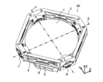
- FIG. 1 is a perspective view of a telescope device having a lock device according to Embodiment 1.
- FIG. 1 is a front view of a telescope device having a lock device according to Embodiment 1.
- FIG. 1 is a plan view of a telescope device having a lock device according to Embodiment 1.
- FIG. 1 is a right side view of a telescope device having a lock device according to Embodiment 1.
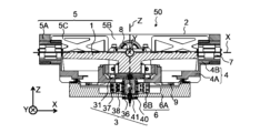
- FIG. 1 is a sectional view of a telescope device having a lock device according to a first embodiment.
- FIG. 3 is a perspective view of a primary mirror tilting holding section included in the telescope device having the locking device according to the first embodiment.
- FIG. 2 is a plan view of the telescope device having the lock device according to Embodiment 1 with the primary mirror and the top of the lock device removed.
- FIG. 2 is a plan view of the telescope device having the locking device according to the first embodiment with the primary mirror and the X-axis member removed.
- 1 is a perspective view of a locking device according to Embodiment 1.
- FIG. 3 is a front view of the locking device according to the first embodiment.
- FIG. 3 is a right side view of the locking device according to the first embodiment.
- FIG. 2 is a plan view of the locking device according to the first embodiment.
- FIG. 2 is a perspective view of the locking device according to the first embodiment with a guide plate spring removed.
- FIG. 3 is a front view of the locking device according to the first embodiment with the guide leaf spring removed.
- FIG. 3 is a right side view of the locking device according to the first embodiment with the guide leaf spring removed.
- FIG. 3 is a plan view of the locking device according to the first embodiment with a guide leaf spring removed.
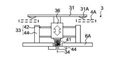
- FIG. 3 is a diagram illustrating the operating principle of the locking device according to the first embodiment.
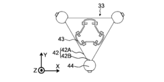
- FIG. 3 is a perspective view of a guide plate spring included in the locking device according to the first embodiment.
- FIG. 3 is a front view of a guide plate spring included in the locking device according to the first embodiment.
- FIG. 3 is a right side view of a guide plate spring included in the locking device according to the first embodiment.
- FIG. 3 is a plan view of a guide plate spring included in the locking device according to the first embodiment.
- FIG. 3 is a diagram illustrating the operating principle of a guide plate spring included in the locking device according to the first embodiment.
- Embodiment 1 The structure of a telescope device having a lock device according to Embodiment 1 of the present disclosure will be described with reference to FIGS. 1 to 8.
- 1 to 4 are a perspective view, a front view, a top view, and a right side view of the telescope device, respectively.
- FIG. 5 is a cross-sectional view of the telescope device taken along the line AA shown in FIG. The AA cross section is a cross section parallel to the XZ plane passing through the center of the primary mirror 1.
- FIG. 6 is a perspective view of a primary mirror tilting holding section included in the telescope device.
- FIG. 7 is a plan view of the telescope device with the primary mirror and the top of the lock device removed.
- FIG. 8 is a plan view of the telescope device with the primary mirror and the X-axis member removed.
- the Z-axis is an axis perpendicular to the plane of the structure 70 (shown in FIG. 10) to which the telescope device 50 is fixed.
- a plane perpendicular to the Z-axis is called a horizontal plane.
- the X axis and the Y axis are defined as two orthogonal axes on a horizontal plane.
- the X-axis and the Y-axis are defined to coincide with the two rotation axes along which the telescope device 50 changes its pointing direction.
- the Z axis passes through the intersection of the X and Y axes.
- the point of intersection where the X, Y, and Z axes are orthogonal to each other is defined as the origin of the XYZ coordinate system.
- the direction moving away from the structure 70 is defined as the positive direction of the Z-axis.
- the side with a larger Z coordinate is conveniently called the upper side, and the side with a smaller Z coordinate is called the lower side.
- the telescope device 50 is a telescope mounted on an artificial satellite.
- the telescope device 50 includes a primary mirror 1 , a primary mirror tilting holder 2 , and a locking device 3 .
- the primary mirror 1 is, for example, a concave mirror with a diameter of about 300 mm.
- the primary mirror 1 reflects observation light.
- the primary mirror tilt holding unit 2 holds the primary mirror 1 rotatably around the X-axis and the Y-axis.
- the X axis and the Y axis are two orthogonal rotation axes that exist on the same plane. In FIG. 1 and the like, the X axis is shown by a dashed line, and the Y axis is shown by a chain double dotted line.
- the Z axis is indicated by a long dashed line.
- the locking device 3 can lock the primary mirror tilting holder 2 so that it does not move with respect to a structure 70 (shown in FIG. 10) to which the telescope device 50 is fixed, and can release the lock to prevent the primary mirror tilting holder 2 from moving. It is a device that can be made to move.
- the primary mirror tilt holding unit 2 is rotated around the X-axis and the Y-axis (changes the tilt angle) during observation with the telescope device 50, and the pointing direction of the primary mirror 1 is scanned.
- the primary mirror 1 in the primary mirror tilt holding section 2 is the driving target that is rotatable around two rotation axes.
- the primary mirror tilting holding section 2 has three main frames. The three frames are the X-axis member 4, the Y-axis member 5, and the fixing member 6. Furthermore, the primary mirror tilt holding section 2 has an X bearing section 7 and a Y bearing section 8.
- the X-axis member 4 holds the primary mirror 1.
- the Y-axis member 5 holds the X-axis member 4 rotatably around the X-axis.
- the fixed member 6 holds the Y-axis member 5 rotatably around the Y-axis.
- the fixing member 6 is fixed to the artificial satellite.
- An artificial satellite is a structure 70 to which the telescope device 50 is fixed.
- the X-bearing portion 7 allows the X-axis member 4 to rotate relative to the Y-axis member 5.
- a Y-bearing portion 8 is provided between the Y-axis member 5 and the fixed member 6.
- the Y-bearing portion 8 allows the Y-axis member 5 to rotate relative to the fixed member 6.
- the X bearing section 7 and the Y bearing section 8 have similar structures, and have a structure in which both ends of the rotating shaft are held via bearings by members provided with holes for holding the rotating shaft.
- the Y-axis member 5 is connected to the X-bearing section 7 and the Y-bearing section 8 . Therefore, the Y-axis member 5 holds the X-axis member 4 and the primary mirror 1, and allows the X-axis member 4 and the primary mirror 1 to rotate around the X-axis and the Y-axis with respect to the fixed member 6.
- the X-axis member 4 is rotatable with two degrees of freedom relative to the fixed member 6.
- the X-axis member 4 and the primary mirror 1 are rotatable with two rotational degrees of freedom about the intersection of the X-axis and the Y-axis existing on the same plane as the center of rotation.
- a structure, such as the primary mirror tilting holding unit 2, in which a member that holds a driven object has two rotational degrees of freedom with respect to a fixed member, and two rotation axes are perpendicular to each other on the same plane is called a gimbal mechanism.
- the primary mirror tilt holding unit 2 drives the primary mirror 1 .
- the X-axis is the first rotation axis.
- the Y-axis is a second rotation axis that is on the same plane as the first rotation axis and perpendicular to the first rotation axis.
- the X-axis member 4 is a first holding part that holds a driven object.
- the Y-axis member 5 is a second holding portion that holds the X-axis member 4 rotatably around the X-axis.
- the fixed member 6 holds the Y-axis member 5 rotatably around the Y-axis.
- the primary mirror tilt holding unit 2 is symmetrical with respect to the XZ plane.
- the primary mirror tilt holding unit 2 is symmetrical with respect to the YZ plane. Therefore, the X-axis member 4, Y-axis member 5, and fixing member 6 are also symmetrical with respect to the XZ plane and symmetrical with respect to the YZ plane.
- the direction parallel to the Z axis is called the vertical direction.
- the Y-axis member 5, and the fixed member 6 the side on which the primary mirror 1 exists in the vertical direction is called the primary mirror side.
- the primary mirror side is the side where the primary mirror 1, which is the driving target of the primary mirror tilt holding unit 2, is present.
- the primary mirror side is also called the drive target side.
- the fixing member side In the primary mirror 1, the X-axis member 4, and the Y-axis member 5, the side where the fixing member 6 is present is called the fixing member side. In the vertical direction, the X-axis member 4 and the Y-axis member 5 are present on the primary mirror side of the fixed member 6. The ends of the X-axis member 4, Y-axis member 5, and fixing member 6 on the primary mirror side are located at approximately the same position in the vertical direction.
- the X-axis member 4 has a primary mirror holding section 4A and two X-bearing holding sections 4B.
- the primary mirror holding section 4A is a disk-shaped member that holds the primary mirror 1.
- the X-bearing holding portion 4B is a member provided with a through hole having a circular cross section.
- the two X-bearing holding parts 4B are provided at positions around the primary mirror holding part 4A through which the X-axis passes.
- the X-bearing holding part 4B is provided perpendicularly to the side surface of the primary mirror holding part 4A.
- the Y-axis member 5 is an octagonal tube that has a substantially octagonal outer shape when viewed from the vertical direction, and whose height is shorter than the length of its sides.
- the octagonal outer shape of the Y-axis member 5 has four long sides (long sides) and four short sides (short sides) arranged alternately. The two opposing short sides are parallel to the X axis. The other two opposing short sides are parallel to the Y axis.
- a through hole having a circular cross section is provided at the center of the side surface of the Y-axis member 5 corresponding to the four short sides.
- Two side surfaces corresponding to two short sides parallel to the Y-axis of the Y-axis member 5 are referred to as an X-bearing holding portion 5A.
- the two side surfaces corresponding to the two short sides parallel to the X-axis are called Y-bearing holding portions 5B.
- the side surfaces corresponding to the four long sides of the Y-axis member 5 are called a frame structure section 5C.
- the fixing member 6 has a structure fixing part 6A and two Y bearing holding parts 6B.
- the structure fixing portion 6A is a substantially flat member having a substantially octagonal outer shape.
- the structure fixing portion 6A is fixed to the structure 70.
- a circular through hole is provided in the center of the structure fixing portion 6A.
- the through hole provided in the structure fixing portion 6A is provided so that its center axis coincides with the Z axis.
- the Y bearing holding portion 6B is a member provided with a through hole having a circular cross section.
- the two Y-bearing holding parts 6B are provided at positions where the Y-axis can be held in the periphery of the structure fixing part 6A.
- the Y-bearing holding part 6B is provided perpendicularly to the structure fixing part 6A.
- the through holes provided in the X-bearing holding part 4B, the X-bearing holding part 5A, the Y-bearing holding part 5B, and the Y-bearing holding part 6B are all provided in parallel to the XY plane, and all have the same diameter.
- the X-axis member 4 is arranged with respect to the Y-axis member 5 such that the X-bearing holding part 4B is adjacent to the X-bearing holding part 5A. At this time, the center axes of the through holes of the X-bearing holding part 4B and the X-bearing holding part 5A are made to coincide.
- the X bearing portion 7 is provided in the through hole of the X bearing holding portion 4B and the X bearing holding portion 5A.
- the Y-axis member 5 is arranged with respect to the fixed member 6 such that the Y-bearing holding part 5B is adjacent to the Y-bearing holding part 6B. At this time, the central axes of the through holes of the Y-bearing holding part 5B and the Y-bearing holding part 6B are aligned.
- the Y bearing portion 8 is provided in the through hole of the Y bearing holding portion 5B and the Y bearing holding portion 6B. By doing so, the X-axis member 4 becomes rotatable around the X-axis and the Y-axis.
- the voice coil motor 9 exists between the fixed member 6 and the X-axis member 4.
- the voice coil motor 9 is a direct-acting motor. When the voice coil motor 9 operates, the distance between the fixed member 6 and the X-axis member 4 at the location where the voice coil motor 9 is installed changes.
- Two of the four voice coil motors 9 are provided on two straight lines forming an angle of 45 degrees with respect to the X-axis and the Y-axis in the XY plane.
- the distances between the four voice coil motors 9 and the intersections of the X and Y axes are all the same.
- the four voice coil motors 9 are arranged so as to be orthogonal to a straight line connecting their installation positions and the intersection of the X and Y axes.
- the primary mirror 1 can be directed at a specified angle ( ⁇ x, ⁇ y) with respect to the structural member 6.
- the primary mirror 1 is supported by a fixed member 6 via four bearings. If they are not locked, there is a risk that the primary mirror 1, the X-axis member 4, and the Y-axis member 5 will move significantly during launch and be destroyed.
- the locking device 3 locks the primary mirror tilting holding part 2 with high rigidity so that it does not move during launch. After the satellite reaches the orbit, the primary mirror tilting holder 2 is released so that the primary mirror 1 can be driven so that observation can be performed using the telescope device 50.
- the locking device 3 is provided at a position on the structure side through which the optical axis (Z-axis) of the primary mirror 1 passes.
- the main part of the locking device 3 is arranged between the X-axis member 4 and the fixing member 6.
- the locking device 3 fixes the X-axis member 4 to the fixing member 6.
- the locking device 3 holds the X-axis member 4 between members arranged on the primary mirror side and the fixed member side. By doing so, the lock device 3 locks the X-axis member 4 so that it does not move relative to the fixed member 6.
- the locking device 3 is in a locked state so that the primary mirror tilting holding part 2 does not move so that members such as the primary mirror 1 are not damaged.
- the locking device 3 makes the primary mirror tilting holder 2 movable.
- the lock device 3 locks the X-axis member 4 so that it does not move relative to the fixed member 6, or allows the X-axis member 4 to move relative to the fixed member 6.
- FIGS. 9 to 22 are a perspective view, a front view, a right side view, and a plan view of the lock device 3 according to the first embodiment, respectively.
- 13 to 16 are a perspective view, a front view, a right side view, and a plan view of the locking device 3 with the guide leaf spring removed.
- FIG. 17 is a diagram illustrating the operating principle of the lock device 3.
- FIG. 17(A) shows a state in which the locking device 3 is not locked. In FIG. 17(A), no locking force is applied to the primary mirror holding portion 4A.
- FIG. 17(B) shows a state in which the locking device 3 is locked.
- FIG. 17(A) shows a state in which the locking device 3 is locked.
- 17(B) shows the forces acting on the locking device 3 and the primary mirror holding portion 4A.
- 18 to 21 are a perspective view, a front view, a right side view, and a plan view of the guide leaf spring included in the locking device 3, respectively.
- FIG. 22 is a diagram illustrating the operating principle of the guide plate spring.
- the locking device 3 is disposed only on the side closer to the fixed member than the primary mirror 1.
- the locking device 3 roughly includes a primary mirror-side holding portion 31, a link mechanism 32, a guide plate spring 33, a wire 34, and a wire locking portion 35 (shown in FIG. 10).
- the primary mirror side holding part 31 exists between the X-axis member 4 and the primary mirror 1.
- the portions of the locking device 3 other than the primary mirror side presser portion 31 are located closer to the fixed member than the X-axis member 4.
- the primary mirror side holding part 31 is a member that presses the X-axis member 4 from the primary mirror side.
- the primary mirror side holding part 31 is a plate material having a triangular shape with rounded corners.
- the link mechanism 32 is a mechanism that generates a force that pushes the X-axis member 4 from the fixed member side.
- the link mechanism 32 has a Y-shape when viewed from the vertical direction.
- the guide leaf spring 33 is a member that restricts the link mechanism 32 from moving only in the Z-axis direction.
- the guide plate spring 33 has a triangular shape with rounded corners when viewed from the vertical direction.
- the triangular shape of the guide leaf spring 33 has a shape that is upside down from the triangle of the primary mirror side holding part 31 in the figure, and is slightly smaller in size than the primary mirror side holding part 31 .
- the wire 34 and the wire locking portion 35 switch whether or not to lock the locking device 3.
- One end of the wire 34 is connected to the link mechanism 32.
- the other end of the wire 34 is locked to a wire locking portion 35 or released.
- the locking device 3 is locked.
- the other end of the wire 34 is released from the wire locking portion 35, the locking device 3 is not locked.
- the link mechanism 32 includes a central drive section 36, a fixed member side presser section 37, a support section 38, a link 39, a structure side member 40, and a return spring 41.
- the central drive section 36 has a portion that passes through a through hole provided at the center of the X-axis member 4.
- the central drive section 36 is connected to the primary mirror side holding section 31 .
- One end of the wire 34 is connected to the central drive section 36 .
- the central drive section 36 is a force transmission section that transmits the force pulled toward the fixed member by the wire 34 to the primary mirror side presser section 31 as a force that causes the primary mirror side presser section 31 to press the X-axis member 4 from the primary mirror side. .
- the fixed member side pressing part 37 is a member that presses the X-axis member 4 from the fixed member side.
- the central drive portion 36, the fixed member side presser portion 37, the support portion 38, and the link 39 operate like a lever with the support portion 38 as a fulcrum.
- the link 39 is a lever, the central drive part 36 is a point of force of the lever, the support part 38 is a fulcrum, and the fixed member side presser part 37 is a point of action.
- the primary mirror tilt holding section 2 In the primary mirror tilt holding section 2 in the released state shown in FIG. 18(A), when the central drive section 36 is pulled and moved toward the fixed member, the fixed member side presser section 37 is moved toward the primary mirror section by the link 39. do.
- the link mechanism 32 converts the tensile force, which is the force by which the central drive part 36 is pulled toward the fixed member, into a force by which the fixed member side pressing part 37 pushes the X-axis member 4 from the fixed member side.
- the primary mirror tilt holding section 2 enters the locked state shown in FIG. 18(B). In the locked state, the primary mirror side presser 31 and the fixed member side presser 37 firmly sandwich the X-axis member 4 from both sides, and the X-axis member 4 does not move relative to the fixed member 6.
- the structure side member 40 is a member fixed to the structure side surface of the structure fixing portion 6A of the fixing member 6.
- the structure side member 40 is fixed to the structure fixing part 6A around a through hole provided in the center of the structure fixing part 6A.
- the structure side member 40 has a through hole in the center through which the wire 34 passes.
- the return spring 41 is present between the structure side member 40 and the central drive part 36.
- the wire 34 passes inside the return spring 41.
- the return spring 41 moves the central drive section 36 toward the primary mirror.
- the fixed member side presser section 37 which is connected to the central drive section 36 through the link 39, moves toward the fixed member.
- the primary mirror tilting holding section 2 enters the released state shown in FIG. 18(A).
- the X-axis member 4 is no longer restrained by the primary mirror side presser 31 and the fixed member side presser 37. Since the structure side member 40 is fixed to the fixed member 6, it can be considered as a part of the fixed member 6.
- the return spring 41 can be considered to be provided between the fixing member 6 and the central drive 36 .
- the locking device 3 has a primary mirror side holding part 31 on top and a link mechanism 32 on the bottom of the X-axis member 4, which has two rotational degrees of freedom, and locks the X-axis member 4 by sandwiching it from above and below.
- the locking device 3 is operated from above and below by three points at the tips of three protrusions 31A provided on the lower surface of the primary mirror side presser 31 and the upper surface of the fixed member side presser 37 arranged at a position corresponding to the protrusion 31A.
- the X-axis member 4 is sandwiched between them.
- the upper surface of the fixed member side presser portion 37 and the lower surface of the X-axis member 4 are flat. Since the X-axis member 4 is locked at three points, it is restrained with high rigidity in all directions.
- the central drive section 36 is connected to the primary mirror side presser section 31 via a link 39. Therefore, by pulling the wire 34 toward the fixed member, a force is generated by the primary mirror side presser portion 31 to push the X-axis member 4 from the primary mirror side.
- the link mechanism 32 is a mechanism that converts the force of pulling the wire 34 into the force of pushing the X-axis member 4 from the fixed member side.
- the wire locking portion 35 is a member that locks the other end of the wire 34 at a predetermined position.
- the wire locking portion 35 is a device that switches whether or not the locking device 3 locks. When the wire locking portion 35 locks the other end of the wire 34, the locking device 3 is in a locked state (locked state).
- the locking device 3 When the wire locking portion 35 does not lock the other end of the wire 34, the locking device 3 is in an unlocked state (released state). In the released state, the X-axis member 4 is movable relative to the fixed member 6. The fact that the X-axis member 4 is movable relative to the fixed member 6 means that the primary mirror tilting holder 2 is movable relative to the structure 70.
- a part of the return spring 41 is arranged so as to enter the through hole of the structure fixing part 6A.
- the return spring 41 is present between the structure side member 40 and the central drive part 36.
- the wire 34 passes through the return spring 41.
- the return spring 41 is compressed.
- the return spring 41 returns to its uncompressed length, moving the central drive 36 further away from the fixing member 6.
- the return spring 41 is an elastic body that is provided between the central drive section 36 and the fixed member 6 and is compressed when the X-axis member 4 is locked so that it does not move relative to the fixed member 6.
- a mechanism different from the return spring 41 may be used to move the primary mirror side presser part 31 and the fixed member side presser part 37 to a position away from the X-axis member 4 in the released state.
- the link mechanism 32 has one central drive section 36 and three sets of a fixed member side presser section 37, a support section 38, and a link 39.
- the three fixing member side pressers 37 are arranged at the vertices of an equilateral triangle when viewed from the vertical direction.
- the primary mirror side holding portion 31 has a substantially triangular shape when viewed from the vertical direction. Near the apex of the substantially triangular shape of the primary mirror side presser 31, three fixed member side pressers 37 are present on the fixed member side surface of the X-axis member 4. Therefore, the three fixed member side pressers 37 and the one primary mirror side presser 31 can firmly sandwich the X-axis member 4 from both sides.
- a conical protrusion 31A is provided on the fixing member side surface of the primary mirror side presser 31 near the apex of the substantially triangular shape of the primary mirror side presser 31.
- the position where the protrusion 31A is provided is a position corresponding to the fixing member side presser part 37 in the XY plane.
- a depression 4C having a conical side surface is provided on the primary mirror side surface of the X-axis member 4 at a position corresponding to the projection 31A.
- the protrusion 31A and the depression 4C physically prevent rotation and slippage in the locking device 3.
- the protrusion 31A may have a truncated cone shape or other shapes.
- the depression 4C may have any shape as long as the projection 31A can fit therein. It is desirable that the shapes of the protrusion 31A and the depression 4C are such that no gap occurs between them.
- the depression 4C is a concave portion provided on the primary mirror side surface of the X-axis member 4 at a position where the primary mirror side presser portion 31 comes into contact.
- the protrusion 31A is a convex portion that fits into a concave portion.
- the protrusion 31A is provided on the surface of the primary mirror-side holding portion 31 on the fixing member side.
- the surface of the primary mirror side holding portion 31 on the fixed member side is the surface adjacent to the X-axis member 4 primary mirror holding portion 4A.
- the locking device may be one in which a recess is not provided on the surface of the X-axis member 4 on the primary mirror side, and a convex portion is not provided on the side of the primary mirror-side holding portion 31 where the X-axis member 4 is present.
- the central drive section 36 is shared by three sets of support sections 38, a fixed member side presser section 37, and a link 39.
- the central drive section 36 is arranged at the center of gravity of the equilateral triangle formed by the fixed member side presser section 37.
- the position where the central drive unit 36 is arranged is also the position through which the Z axis passes.
- the central drive section 36, the support column 38, and the fixed member side presser section 37 extend parallel to the Z-axis.
- the central drive section 36, the support section 38, and the fixed member side presser section 37 exist in a straight line in the XY plane such that the support section 38 exists between the center drive section 36 and the fixed member side press section 37.
- the support column 38 is fixed to the fixed member 6.
- the link 39 is rotatably connected to the central drive section 36, the support section 38, and the fixed member side presser section 37.
- the link 39 operates like a lever, and the fixed member side presser section 37 moves to the opposite side of the Z-axis direction from the central drive section 36. do.
- Two links 39 are provided for one set of the central drive section 36, the support section 38, and the fixed member side presser section 37. Therefore, even if the central drive section 36 and the fixed member side presser section 37 move, the central drive section 36, the support section 38, and the fixed member side presser section 37 maintain a parallel relationship with each other.
- the central drive section 36 has a portion that penetrates the X-axis member 4.
- the central drive section 36 is connected to the primary mirror side holding section 31 .
- the relative positional relationship between the central drive section 36 and the primary mirror side presser section 31 is fixed.
- the central drive part 36 exists between the X-axis member 4 and the fixed member 6.
- the central drive unit 36 is a columnar body extending in the Z-axis direction and having the same outer shape on the XY plane.
- the support portion 38 and the fixing member side presser portion 37 have an approximately cylindrical outer shape.
- the primary mirror side holding part 31 is a driving object side holding part that presses the X-axis member 4 from the side where the driving object exists.
- the fixed member side pressing part 37 presses the X-axis member 4 from the side where the fixed member 6 is present.
- the support column 38 is arranged between the central drive section 36 and the fixed member side presser section 37 when viewed from the vertical direction.
- the link 39 is rotatably connected to the central drive section 36, the support section 38, and the fixed member side presser section 37.
- the link 39 moves the fixed member side presser portion 37 in a direction toward the X-axis member 4 when the central drive portion 36 moves in a direction away from the X-axis member 4 .
- the link 39 moves the fixed member side presser portion 37 in a direction away from the X-axis member 4 when the central drive portion 36 moves in a direction toward the X-axis member 4 .
- the wire locking portion 35 includes a wire engagement pin 35A, a locking structure portion 35B, and a pin drive portion 35C.
- the wire engagement pin 35A is a pin that engages the other end of the ring-shaped wire 34.
- the wire engagement pin 35A comes out from the pin drive section 35C.
- the locking structure portion 35B is a member provided with a through hole through which the wire engagement pin 35A passes, and to which the pin drive portion 35C is attached.
- the locking structure portion 35B is fixed to the structure 70.
- the pin drive portion 35C is located on the opposite side of the locking structure portion 35B from the side where the wire engagement pin 35A engages with the wire 34.
- the pin drive section 35C is attached to the surface of the locking structure section 35B where the through hole is provided so that the wire engagement pin 35A passes through the through hole.
- the pin driving section 35C changes the length of the wire engagement pin 35A.
- the pin drive section 35C shortens the length of the wire engagement pin 35A, the wire engagement pin 35A no longer engages with the other end of the wire 34.
- the length of the wire 34 is such that the lock device 3 is in a locked state when the other end of the wire 34 is engaged with the wire engagement pin 35A.
- the pin driving section 35C is set in an operation mode in which the length of the wire engagement pin 35A is maintained in a long state. In this state, the other end of the wire 34 is engaged with the wire engagement pin 35A. In this way, the locking device 3 becomes locked.
- a release control signal is sent to the pin drive unit 35C.
- the pin drive section 35C shortens the length of the wire engagement pin 35A.
- the other end of the wire 34 no longer engages with the wire engagement pin 35A, and the return spring 41 moves the central drive section 36 and the primary mirror side presser section 31 to the released position. In this way, the primary mirror tilt holding section 2 becomes movable relative to the structure 70.
- the wire 34 and the wire locking part 35 generate a tensile force that pulls the central drive part 3 toward the fixed member, and the primary mirror side holding part 31 and the fixed member side holding part 37 sandwich the X-axis member 4.
- This is a locking force generating part that locks the X-axis member 4 against the fixed member 6 so that it does not move.
- the guide plate spring 33 is a movement direction regulating part that regulates the central drive part 36 to move only in the Z-axis direction.
- the guide plate spring 33 prevents the central drive unit 36 from tilting in a direction other than the Z-axis direction when the primary mirror tilt holding unit 2 is in the released state.
- the guide leaf spring 33 has one leaf spring portion 42 , two central drive portion attachment portions 43 , and three fixing member attachment portions 44 .
- the central drive section attachment section 43 is a member that attaches the leaf spring section 42 to the central drive section 1 .
- the fixing member attachment part 44 is a member that attaches the leaf spring part 42 to the fixing member 6.
- the leaf spring portion 42 has two main surface portions 42A parallel to the XY plane and three side surface portions 42B connecting the main surface portions 42A.
- the main surface portion 42A has a substantially equilateral triangular outer shape when viewed from the vertical direction.
- the main surface portion 42A is a plate spring having appropriate elasticity.
- a through hole having the same cross-sectional shape as the central drive section 36 in the XY plane is provided in the center of the main surface section 42A.
- the side surface portion 42B is a member that connects the main surface portions 42A in the Z-axis direction near the apex of the equilateral triangle of the main surface portions 42A.
- the central drive unit mounting portion 43 is provided perpendicularly to the main surface portion 42A along the edge of a through hole provided in the main surface portion 42A on the upper side of the upper main surface portion 42A and the upper side of the lower main surface portion 42A in the figure. established in The central drive section attachment section 43 is attached to the central drive section 36 .
- the side surface portion 42B of the plate spring portion 42 is attached to the fixing member attachment portion 44.
- the lower end of the fixing member attaching portion 44 in the figure is attached to the fixing member 6.
- the main surface portion 42A is a plate spring that has a hole through which the central driving portion 36 passes and is fixed to the central driving portion 36.
- the side surface portion 42B and the fixing member attachment portion 44 are plate spring fixing portions that fix the two main surface portions 42A to the fixing member 6.
- the central drive section 36 is connected to the fixed member 6 via the guide plate spring 33.
- the leaf spring portion 42 of the guide leaf spring 33 can be deformed in the Z-axis direction (vertical direction), but hardly deformed in the direction parallel to the XY plane. As shown in FIG. 22, the guide leaf spring 33 can restrict the moving direction of the central drive section 36 so that the central drive section 36 moves only in the vertical direction.
- the lock device 3 is in a locked state.
- the wire 34 is connected at one end to the lower end of the central drive section 36 .
- the other end of the wire 34 is looped.
- the length of the wire 34 is such that when the other end is hung on the wire engagement pin 35A of the wire locking part 35, the primary mirror side presser part 31 and the fixed member side presser part 37 apply necessary and sufficient force to the X-axis member. Make it long enough to press 4. Therefore, the X-axis member 4 cannot move relative to the fixed member 6 while the other end of the wire 34 is hooked to the wire engagement pin 35A. With tension applied to the wire 34, the loop at the other end of the wire 34 is hung on the wire engagement pin 35A.
- the pin drive unit 35C maintains the wire engagement pin 35A in a long state and keeps the wire engagement pin 35A in a state where it does not move against the load from the wire 34.
- a rocket carrying a satellite etc. is launched.
- a locking device 3 locks the X-axis member 4 so that it cannot move relative to the fixed member 6.
- the primary mirror 1 and the X-axis member 4 do not move even with the force applied during launch.
- the primary mirror 1 and the primary mirror tilting holder 2 are launched into outer space without being damaged.
- a control signal is sent to the pin drive unit 35C to shorten the wire engagement pin 35A.
- the pin driving section 35C that has received the control signal shortens the wire engagement pin 35A.
- the ring at the other end of the wire 34 comes off the wire engagement pin 35A, and the wire 34 becomes movable.
- the force compressing the return spring 41 disappears, and the return spring 41 returns to its original length.
- the primary mirror side presser 31 moves upward, and the fixed member side presser 37 moves downward.
- the primary mirror tilt holder 2 can now rotate within a predetermined angular range around the X-axis and the Y-axis.
- Observation of an observation target such as a celestial body is started using the telescope device 50.
- the voice coil motor 9 is controlled so that the primary mirror 1 is scanned so as to face in a designated direction, and the telescope device 50 observes the observation target.
- the link mechanism 32 may tilt with respect to the Z-axis. If the link mechanism 32 is tilted, the link mechanism 32 and the X-axis member 4 may interfere with each other. If the link mechanism 32 and the X-axis member 4 interfere and come into contact, either or both of the link mechanism 32 or the X-axis member 4 (including the primary mirror 1) may be damaged.
- the guide plate spring 33 prevents the link mechanism 32 and the X-axis member 4 from interfering with each other by restricting the central drive section 36 to move only in the Z-axis direction. By forming the leaf spring part 42 into a triangular shape, the central drive part 36 is prevented from twisting around the Z axis, and the stress acting between the leaf spring part 42 and the central drive part 36 is alleviated. .
- the lock device 3 has a simpler structure than the structure disclosed in Patent Document 1.
- the locking device 3 can lock the primary mirror tilting holding part 2 with a necessary and sufficient force to prevent it from moving against a large load applied at the time of launch.
- the lock device 3 is scheduled to be applied to a telescope device mounted on the solar observation satellite Solar-C.
- the primary mirror side holding part 31 may not have a triangular shape, but may have a substantially Y-shaped shape connecting the corresponding positions of the three fixing member side holding parts 37 and the vicinity where the Z axis passes.
- the primary mirror side presser part 31 is provided at a position corresponding to the fixed member side presser part 37 on the primary mirror side surface of the X-axis member 4, and has a shape that allows the X-axis member 4 to be pushed from the primary mirror side. It can be of any shape.
- the link mechanism 32 may have two or four or more sets of the fixed member side presser portion 37, the support portion 38, and the link 39.
- the central drive section 36 is shared by three sets of the fixed member side presser section 37, the support section 38, and the link 39.
- the linkage may have three central drives 36.
- the locking device does not need to have a guide plate spring.
Landscapes
- Engineering & Computer Science (AREA)
- Physics & Mathematics (AREA)
- General Engineering & Computer Science (AREA)
- Optics & Photonics (AREA)
- General Physics & Mathematics (AREA)
- Astronomy & Astrophysics (AREA)
- Remote Sensing (AREA)
- Aviation & Aerospace Engineering (AREA)
- Mechanical Engineering (AREA)
- Life Sciences & Earth Sciences (AREA)
- Sustainable Development (AREA)
- Aerials With Secondary Devices (AREA)
- Telescopes (AREA)
Priority Applications (3)
| Application Number | Priority Date | Filing Date | Title |
|---|---|---|---|
| US18/850,059 US12332500B2 (en) | 2022-03-30 | 2023-03-29 | Locking device, gimbal mechanism, and telescope device |
| JP2024512709A JP7483178B2 (ja) | 2022-03-30 | 2023-03-29 | ロック装置、ジンバル機構および望遠鏡装置 |
| EP23780739.1A EP4502448A4 (en) | 2022-03-30 | 2023-03-29 | LOCKING DEVICE, GIMMER MECHANISM AND TELESCOPIC DEVICE |
Applications Claiming Priority (2)
| Application Number | Priority Date | Filing Date | Title |
|---|---|---|---|
| JP2022055552 | 2022-03-30 | ||
| JP2022-055552 | 2022-03-30 |
Publications (1)
| Publication Number | Publication Date |
|---|---|
| WO2023190731A1 true WO2023190731A1 (ja) | 2023-10-05 |
Family
ID=88202621
Family Applications (1)
| Application Number | Title | Priority Date | Filing Date |
|---|---|---|---|
| PCT/JP2023/012907 Ceased WO2023190731A1 (ja) | 2022-03-30 | 2023-03-29 | ロック装置、ジンバル機構および望遠鏡装置 |
Country Status (4)
| Country | Link |
|---|---|
| US (1) | US12332500B2 (https=) |
| EP (1) | EP4502448A4 (https=) |
| JP (1) | JP7483178B2 (https=) |
| WO (1) | WO2023190731A1 (https=) |
Families Citing this family (1)
| Publication number | Priority date | Publication date | Assignee | Title |
|---|---|---|---|---|
| DE102023130425B8 (de) * | 2023-11-03 | 2024-12-19 | Dcubed Gmbh | System für einen Satelliten, Trägerplatte und Satellit |
Citations (3)
| Publication number | Priority date | Publication date | Assignee | Title |
|---|---|---|---|---|
| JPS6062205A (ja) | 1983-09-14 | 1985-04-10 | Nec Corp | 人工衛星搭載用アンテナ駆動装置 |
| JPS63305209A (ja) | 1987-06-05 | 1988-12-13 | Toshiba Corp | 2軸ジンバル装置のロンチロック装置 |
| JPH07307703A (ja) * | 1994-05-11 | 1995-11-21 | Mitsubishi Electric Corp | 光空間通信装置および光空間通信装置用のミラー駆動機構 |
Family Cites Families (12)
| Publication number | Priority date | Publication date | Assignee | Title |
|---|---|---|---|---|
| CA752123A (en) * | 1967-02-07 | W. Boothroyd Howard | Gyroscope | |
| DE2436006A1 (de) * | 1974-07-26 | 1976-02-12 | Teldix Gmbh | Festsetzvorrichtung fuer ein kardanisch gelagertes schwungrad |
| US4023891A (en) * | 1975-12-15 | 1977-05-17 | Gte Sylvania Incorporated | Adjustable mirror mount assembly |
| US6626834B2 (en) * | 2001-01-25 | 2003-09-30 | Shane Dunne | Spiral scanner with electronic control |
| US7009752B1 (en) * | 2003-01-21 | 2006-03-07 | Lockheed Martin Corporation | Actively-supported multi-degree of freedom steerable mirror apparatus and method |
| US7336345B2 (en) * | 2005-07-08 | 2008-02-26 | Lockheed Martin Corporation | LADAR system with SAL follower |
| EP2027499A4 (en) * | 2006-06-09 | 2010-01-27 | Bae Systems Information | VERY PRECISE OPTICAL DISPLAY DEVICE |
| US8752969B1 (en) * | 2007-10-15 | 2014-06-17 | Arete Associates | Method of operating a fast scanning mirror |
| WO2009086625A1 (en) * | 2008-01-08 | 2009-07-16 | Abb Bomem Inc. | Stiffness compensation in opto-mechanical mechanisms |
| FR2932164B1 (fr) * | 2008-06-06 | 2010-08-20 | Thales Sa | Dispositif de maintien d'au moins un objet mobile, reutilisable, securise autonome et sans chocs, pour engins spatiaux |
| CN109475976A (zh) * | 2016-07-14 | 2019-03-15 | 三菱电机株式会社 | 激光加工装置 |
| WO2018131472A1 (ja) * | 2017-01-11 | 2018-07-19 | 三菱電機株式会社 | 無反動装置及び指向制御ミラーシステム |
-
2023
- 2023-03-29 US US18/850,059 patent/US12332500B2/en active Active
- 2023-03-29 EP EP23780739.1A patent/EP4502448A4/en active Pending
- 2023-03-29 WO PCT/JP2023/012907 patent/WO2023190731A1/ja not_active Ceased
- 2023-03-29 JP JP2024512709A patent/JP7483178B2/ja active Active
Patent Citations (3)
| Publication number | Priority date | Publication date | Assignee | Title |
|---|---|---|---|---|
| JPS6062205A (ja) | 1983-09-14 | 1985-04-10 | Nec Corp | 人工衛星搭載用アンテナ駆動装置 |
| JPS63305209A (ja) | 1987-06-05 | 1988-12-13 | Toshiba Corp | 2軸ジンバル装置のロンチロック装置 |
| JPH07307703A (ja) * | 1994-05-11 | 1995-11-21 | Mitsubishi Electric Corp | 光空間通信装置および光空間通信装置用のミラー駆動機構 |
Non-Patent Citations (1)
| Title |
|---|
| See also references of EP4502448A4 |
Also Published As
| Publication number | Publication date |
|---|---|
| US12332500B2 (en) | 2025-06-17 |
| JPWO2023190731A1 (https=) | 2023-10-05 |
| EP4502448A1 (en) | 2025-02-05 |
| US20250164741A1 (en) | 2025-05-22 |
| EP4502448A4 (en) | 2025-06-18 |
| JP7483178B2 (ja) | 2024-05-14 |
Similar Documents
| Publication | Publication Date | Title |
|---|---|---|
| US4436260A (en) | Optical scanner for use in confined areas | |
| US4381092A (en) | Magnetic docking probe for soft docking of space vehicles | |
| US4060315A (en) | Precision mirror mount | |
| US8186121B2 (en) | Support device for elements on a piece of space equipment with flexible deploying arms | |
| US6679455B2 (en) | Pointing device and an onboard pointing system | |
| JP7483178B2 (ja) | ロック装置、ジンバル機構および望遠鏡装置 | |
| JPH0155160B2 (https=) | ||
| EP1420179B1 (en) | Flexure-type suspension system providing for three degrees of freedom and flexure-type positioning assembly based thereon | |
| KR20220084029A (ko) | 위성용 분리 시스템 | |
| US11834202B2 (en) | Device for deploying and pointing an equipment item carried by a spacecraft | |
| JPH07307703A (ja) | 光空間通信装置および光空間通信装置用のミラー駆動機構 | |
| CA2959638C (en) | Deployment and aiming device | |
| EP3918209B1 (en) | Piezoelectric braking device | |
| JP2008545152A (ja) | 光学要素の支持装置 | |
| JP5196582B2 (ja) | 可動鏡機構 | |
| JP4375400B2 (ja) | 反射鏡支持機構 | |
| US5181430A (en) | Fine adjustment control mechanism for orientation and/or positioning of a pay load | |
| Yalagach et al. | Deployable barrel for a cubesat's optical payload | |
| US12214909B1 (en) | Dispensing hinge assembly | |
| US12600497B2 (en) | Linked spacecraft dispensing | |
| US20110198447A1 (en) | Actuation system for mobile elements with dynamically compensated and opposite relative motions | |
| WO2025164440A1 (ja) | 反射鏡装置および反射鏡面調整システム | |
| KR102805130B1 (ko) | 구동 장치 및 이를 포함하는 압전형 조종거울 시스템 | |
| US11993406B2 (en) | Device for orienting a load in two orthogonal axes of rotation | |
| JPH08107305A (ja) | アンテナ反射鏡 |
Legal Events
| Date | Code | Title | Description |
|---|---|---|---|
| 121 | Ep: the epo has been informed by wipo that ep was designated in this application |
Ref document number: 23780739 Country of ref document: EP Kind code of ref document: A1 |
|
| WWE | Wipo information: entry into national phase |
Ref document number: 2024512709 Country of ref document: JP |
|
| WWE | Wipo information: entry into national phase |
Ref document number: 18850059 Country of ref document: US |
|
| WWE | Wipo information: entry into national phase |
Ref document number: 2023780739 Country of ref document: EP |
|
| NENP | Non-entry into the national phase |
Ref country code: DE |
|
| ENP | Entry into the national phase |
Ref document number: 2023780739 Country of ref document: EP Effective date: 20241030 |
|
| WWP | Wipo information: published in national office |
Ref document number: 18850059 Country of ref document: US |
|
| WWG | Wipo information: grant in national office |
Ref document number: 18850059 Country of ref document: US |