WO2023190576A1 - 充電制御装置 - Google Patents
充電制御装置 Download PDFInfo
- Publication number
- WO2023190576A1 WO2023190576A1 PCT/JP2023/012637 JP2023012637W WO2023190576A1 WO 2023190576 A1 WO2023190576 A1 WO 2023190576A1 JP 2023012637 W JP2023012637 W JP 2023012637W WO 2023190576 A1 WO2023190576 A1 WO 2023190576A1
- Authority
- WO
- WIPO (PCT)
- Prior art keywords
- charging
- discharge
- mode
- battery
- self
- Prior art date
- Legal status (The legal status is an assumption and is not a legal conclusion. Google has not performed a legal analysis and makes no representation as to the accuracy of the status listed.)
- Ceased
Links
Images


Classifications
-
- H—ELECTRICITY
- H01—ELECTRIC ELEMENTS
- H01M—PROCESSES OR MEANS, e.g. BATTERIES, FOR THE DIRECT CONVERSION OF CHEMICAL ENERGY INTO ELECTRICAL ENERGY
- H01M10/00—Secondary cells; Manufacture thereof
- H01M10/42—Methods or arrangements for servicing or maintenance of secondary cells or secondary half-cells
- H01M10/48—Accumulators combined with arrangements for measuring, testing or indicating the condition of cells, e.g. the level or density of the electrolyte
- H01M10/488—Cells or batteries combined with indicating means for external visualization of the condition, e.g. by change of colour or of light density
-
- H—ELECTRICITY
- H01—ELECTRIC ELEMENTS
- H01M—PROCESSES OR MEANS, e.g. BATTERIES, FOR THE DIRECT CONVERSION OF CHEMICAL ENERGY INTO ELECTRICAL ENERGY
- H01M10/00—Secondary cells; Manufacture thereof
- H01M10/05—Accumulators with non-aqueous electrolyte
- H01M10/052—Li-accumulators
-
- H—ELECTRICITY
- H01—ELECTRIC ELEMENTS
- H01M—PROCESSES OR MEANS, e.g. BATTERIES, FOR THE DIRECT CONVERSION OF CHEMICAL ENERGY INTO ELECTRICAL ENERGY
- H01M10/00—Secondary cells; Manufacture thereof
- H01M10/42—Methods or arrangements for servicing or maintenance of secondary cells or secondary half-cells
- H01M10/44—Methods for charging or discharging
-
- H—ELECTRICITY
- H01—ELECTRIC ELEMENTS
- H01M—PROCESSES OR MEANS, e.g. BATTERIES, FOR THE DIRECT CONVERSION OF CHEMICAL ENERGY INTO ELECTRICAL ENERGY
- H01M10/00—Secondary cells; Manufacture thereof
- H01M10/42—Methods or arrangements for servicing or maintenance of secondary cells or secondary half-cells
- H01M10/44—Methods for charging or discharging
- H01M10/443—Methods for charging or discharging in response to temperature
-
- H—ELECTRICITY
- H01—ELECTRIC ELEMENTS
- H01M—PROCESSES OR MEANS, e.g. BATTERIES, FOR THE DIRECT CONVERSION OF CHEMICAL ENERGY INTO ELECTRICAL ENERGY
- H01M10/00—Secondary cells; Manufacture thereof
- H01M10/42—Methods or arrangements for servicing or maintenance of secondary cells or secondary half-cells
- H01M10/46—Accumulators structurally combined with charging apparatus
-
- H—ELECTRICITY
- H01—ELECTRIC ELEMENTS
- H01M—PROCESSES OR MEANS, e.g. BATTERIES, FOR THE DIRECT CONVERSION OF CHEMICAL ENERGY INTO ELECTRICAL ENERGY
- H01M10/00—Secondary cells; Manufacture thereof
- H01M10/42—Methods or arrangements for servicing or maintenance of secondary cells or secondary half-cells
- H01M10/48—Accumulators combined with arrangements for measuring, testing or indicating the condition of cells, e.g. the level or density of the electrolyte
-
- H—ELECTRICITY
- H01—ELECTRIC ELEMENTS
- H01M—PROCESSES OR MEANS, e.g. BATTERIES, FOR THE DIRECT CONVERSION OF CHEMICAL ENERGY INTO ELECTRICAL ENERGY
- H01M10/00—Secondary cells; Manufacture thereof
- H01M10/42—Methods or arrangements for servicing or maintenance of secondary cells or secondary half-cells
- H01M10/48—Accumulators combined with arrangements for measuring, testing or indicating the condition of cells, e.g. the level or density of the electrolyte
- H01M10/486—Accumulators combined with arrangements for measuring, testing or indicating the condition of cells, e.g. the level or density of the electrolyte for measuring temperature
-
- H—ELECTRICITY
- H02—GENERATION; CONVERSION OR DISTRIBUTION OF ELECTRIC POWER
- H02J—ELECTRIC POWER NETWORKS; CIRCUIT ARRANGEMENTS OR SYSTEMS FOR SUPPLYING OR DISTRIBUTING ELECTRIC POWER; SYSTEMS FOR STORING ELECTRIC ENERGY
- H02J7/00—Circuit arrangements for charging or discharging batteries or for supplying loads from batteries
-
- H—ELECTRICITY
- H02—GENERATION; CONVERSION OR DISTRIBUTION OF ELECTRIC POWER
- H02J—ELECTRIC POWER NETWORKS; CIRCUIT ARRANGEMENTS OR SYSTEMS FOR SUPPLYING OR DISTRIBUTING ELECTRIC POWER; SYSTEMS FOR STORING ELECTRIC ENERGY
- H02J7/00—Circuit arrangements for charging or discharging batteries or for supplying loads from batteries
- H02J7/02—Circuit arrangements for charging or discharging batteries or for supplying loads from batteries for charging batteries from AC mains by converters
- H02J7/04—Regulation of charging current or voltage
-
- H—ELECTRICITY
- H01—ELECTRIC ELEMENTS
- H01M—PROCESSES OR MEANS, e.g. BATTERIES, FOR THE DIRECT CONVERSION OF CHEMICAL ENERGY INTO ELECTRICAL ENERGY
- H01M2220/00—Batteries for particular applications
- H01M2220/20—Batteries in motive systems, e.g. vehicle, ship, plane
-
- Y—GENERAL TAGGING OF NEW TECHNOLOGICAL DEVELOPMENTS; GENERAL TAGGING OF CROSS-SECTIONAL TECHNOLOGIES SPANNING OVER SEVERAL SECTIONS OF THE IPC; TECHNICAL SUBJECTS COVERED BY FORMER USPC CROSS-REFERENCE ART COLLECTIONS [XRACs] AND DIGESTS
- Y02—TECHNOLOGIES OR APPLICATIONS FOR MITIGATION OR ADAPTATION AGAINST CLIMATE CHANGE
- Y02E—REDUCTION OF GREENHOUSE GAS [GHG] EMISSIONS, RELATED TO ENERGY GENERATION, TRANSMISSION OR DISTRIBUTION
- Y02E60/00—Enabling technologies; Technologies with a potential or indirect contribution to GHG emissions mitigation
- Y02E60/10—Energy storage using batteries
Definitions
- the present invention relates to a charging control device that controls charging of a secondary battery.
- a lithium ion battery has an electrolytic solution containing lithium ions between a positive electrode and a negative electrode, and a separator that partitions the electrolytic solution into a positive electrode side and a negative electrode side.
- lithium metal batteries that use lithium metal for the negative electrode have the following issues.
- lithium ions in the electrolyte are stored between the graphite layers, and when discharging, the stored lithium ions are released into the electrolyte.
- lithium metal battery during charging, lithium ions in the electrolyte are deposited as lithium metal on the negative electrode, and during discharging, the lithium metal in the negative electrode is eluted into the electrolyte as lithium ions. Therefore, by repeating charging and discharging, lithium metal is repeatedly deposited and eluted.
- the lithium metal in the negative electrode Due to repeated precipitation and elution, the lithium metal in the negative electrode, which was neatly and neatly crystallized when new, becomes porous and causes dendritic growth, resulting in the formation of a micro short circuit between the negative and positive electrodes.
- the self-discharge rate of lithium metal batteries increases.
- the lithium metal battery can be sufficiently discharged, that is, the lithium metal in the negative electrode can be sufficiently eluted, and then the lithium metal can be charged slowly over a period of time.
- a possible countermeasure is to perform charging using a recovery charge/discharge mode that crystallizes to a certain size.
- the rate of formation of micro short circuits varies depending on various conditions such as the negative electrode, positive electrode, electrolyte, separator, charging and discharging conditions of the lithium metal battery. Therefore, it is difficult to determine at what timing to perform charging in the recovery charge/discharge mode, that is, to determine whether charging in the recovery charge/discharge mode is necessary at any given time.
- the battery voltage as an open circuit voltage of a lithium metal battery is lower than a threshold value, it is determined that there is a slight short circuit, and charging in the recovery charge/discharge mode is determined to be necessary. It is possible that in various batteries including lithium metal batteries, as the storage capacity increases, the drop in open circuit voltage generally decreases even if a slight short circuit path is created. Therefore, compared to the variation in battery voltage between lithium metal batteries, the magnitude of the voltage drop due to a micro short circuit is not large enough, so it is difficult to determine a micro short circuit, and charging in the recovery charge/discharge mode is difficult. It is difficult to judge whether it is necessary or not.
- the present invention has been made in view of the above circumstances, and an object of the present invention is to accurately determine whether or not charging in the recovery charge/discharge mode is necessary.
- the present inventors determined whether or not charging in the recovery charge/discharge mode is necessary based on the magnitude of the battery voltage itself or the magnitude of the self-discharge rate itself, but based on the change in the self-discharge rate over time. The inventors have discovered that the necessity can be determined with high accuracy by making a determination based on the following, and have arrived at the present invention.
- the present invention is a charging control device according to (1) to (9) below.
- a lithium metal battery as a secondary battery using lithium metal as a negative electrode is charged in a predetermined normal charging mode, and the lithium metal battery is once discharged and then charged for a longer time than in the normal charging mode.
- a charging control device that performs charging by a recovery charging/discharging mode, a detection unit that detects a battery voltage as the voltage of the lithium metal battery; a calculation unit that calculates a self-discharge rate of the lithium metal battery based on a change in the battery voltage; a recording unit that records the history of the self-discharge rate; a determination unit that determines whether or not charging in the recovery charge/discharge mode is necessary based on a change in the self-discharge rate in time series in the history;
- a charging control device comprising:
- the necessity of charging in the recovery charge/discharge mode is not determined based on the magnitude of the battery voltage itself or the magnitude of the self-discharge rate itself, but rather based on the time-series change in the self-discharge rate. Judgment is made based on. Therefore, since the past self-discharge rate is compared, the determination can be made with high accuracy even when there is variation in battery voltage between lithium metal batteries. As described above, according to this configuration, it is possible to accurately determine whether or not charging in the recovery charging/discharging mode is necessary.
- the charging control device having a temperature detection unit that detects a battery temperature as the temperature of the lithium metal battery;
- the calculation unit calculates the self-discharge rate at a predetermined temperature and a predetermined charging state based on the detected battery voltage and the detected battery temperature.
- the lithium metal battery is installed in an electric vehicle,
- the determining unit determines whether or not charging in the recovery charging/discharging mode is necessary based on a change in the self-discharging rate with respect to an increase in one of the travel distance and operating time of the electric vehicle.
- the charging control device according to any one of (1) to (5) above.
- the self-discharge rate tends to increase due to increases in mileage and operating time.
- the determination unit determines whether or not charging in the recovery charge/discharge mode is necessary based on the change in self-discharge rate with respect to an increase in either the traveling distance or the operating time, and shifts to the recovery charge/discharge mode. I can do it. Therefore, compared to determining the necessity of charging in the recovery charge/discharge mode based on the change in self-discharge rate with respect to a mere increase in time since new, the system can more accurately determine the necessity of charging and recover the battery. It is possible to shift to charge/discharge mode.
- a temperature detection unit that detects battery temperature as the temperature of the lithium metal battery;
- a discharge current value as a current value at the time of discharging in the recovery charge/discharge mode and a discharge time as the time required for the discharge for each of the plurality of self-discharge rate classifications and for each of the plurality of battery temperature classifications.
- Department and The charging control device according to any one of (1) to (6) above.
- the optimal discharge current value and discharge time vary depending on the self-discharge rate and battery temperature.
- the setting section sets the discharge current value and discharge time based on the table according to the self-discharge rate and battery temperature, it becomes easy to set the optimal discharge current value and discharge time.
- a temperature control unit that allows charging in the recovery charge/discharge mode on the condition that the temperature of the lithium metal battery is equal to or higher than a predetermined temperature;
- the charging control device according to any one of (1) to (7) above.
- the discharge in the recovery charge/discharge mode be performed at a predetermined temperature or higher.
- the temperature control section allows charging in the recovery charge/discharge mode on the condition that the temperature of the lithium metal battery is equal to or higher than a predetermined temperature, so that the lithium metal battery can be efficiently protected.
- the maintenance attention unit can automatically send and release maintenance attention.
- FIG. 1 is a configuration diagram showing an electric vehicle according to a first embodiment. It is a graph showing an example of changes in battery voltage. 2 is a graph showing an example of changes in self-discharge rate. It is a flowchart which shows the flow of charge by recovery charge/discharge mode.
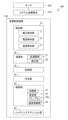
- FIG. 1 is a configuration diagram showing an electric vehicle 200 of this embodiment.
- the electric vehicle 200 includes a motor 220 that serves as a power source for the electric vehicle 200, a lithium metal battery 210 as a secondary battery that supplies power to the motor 220, and a charging control device 100 that controls charging of the lithium metal battery 210. Equipped with
- the lithium metal battery 210 includes a positive electrode, a negative electrode, an electrolytic solution disposed between the positive electrode and the negative electrode, and a separator that partitions the electrolytic solution into a positive electrode side and a negative electrode side.
- the positive electrode is composed of a layer containing a positive electrode active material, a binder, and a conductive additive.
- Li 1 Ni 0.8 Co 0.1 Mn 0.1 O 2 (NCM811) is used as the positive electrode active material.
- the negative electrode includes a negative electrode base material such as a negative electrode current collector or lithium foil, and a lithium metal layer formed by depositing lithium metal on the negative electrode base material.
- the lithium metal battery 210 has a much higher energy density than conventional lithium ion batteries.
- the electrolytic solution includes an organic solvent and an electrolyte.
- the organic solvent may be, for example, a fluorine-substituted chain hydrocarbon such as 1,1,2,2-tetrafluoro-1-(2,2,2-trifluoroethoxy)ethane or methylnona as the first organic solvent.
- Hydrofluoroethers such as fluoroisobutyl ether and methyl nonafluorobutyl ether can be used.
- 1,2-dimethoxyethane DME
- ethylene carbonate EC
- propylene carbonate PC
- sulfolane S
- DMC dimethyl carbonate
- DEC diethyl carbonate
- EMC ethyl Methyl carbonate
- the electrolyte is the source of lithium ions, the charge transfer medium, and contains lithium salts.
- Lithium salts include LiFSI, LiPF 6 , LiBF 4 , LiClO 4 , LiAsF 6 , LiCF 3 SO 3 , LiC(CF 3 SO 2 ) 3 , LiN(CF 3 SO 2 ) 2 (LiTFSI), LiN(FSO 2 ).
- LiFSI LiFSI
- LiPF 6 LiBF 4 , LiClO 4
- LiAsF 6 LiCF 3 SO 3
- LiC(CF 3 SO 2 ) 3 LiN(CF 3 SO 2 ) 2
- LiTFSI LiN(FSO 2
- At least one member selected from the group consisting of 2 (LiFSI) and LiBC 4 O 8 can be used.
- LiFSI can be preferably used as the electrolyte.
- the lithium metal battery 210 supplies power to the motor 220 during power running to accelerate the electric vehicle 200 or maintain the vehicle speed on an uphill slope or the like.
- the electric power supplied from the motor 220 charges the electric vehicle 200 .
- the charging control device 100 controls charging when charging the lithium metal battery 210 using charging equipment. Specifically, the charging control device 100 charges the lithium metal battery 210 in a predetermined normal charging mode and a predetermined recovery charging/discharging mode.
- Charging in normal charging mode is performed using charging equipment located at home, charging spots, etc.
- CC charging is performed in which charging is performed with a charging current of a constant magnitude
- CV charging is performed in which charging is performed with a charging voltage of a constant magnitude.
- Charging in the recovery charge/discharge mode is performed by charging equipment located at a dealer or the like.
- a control program is executed to perform maintenance to restore the capacity, resistance, and self-discharge performance of the lithium metal battery 210, or maintenance to prevent performance deterioration.
- a charge/discharge control program and a battery temperature control program are executed as programs that are different from programs that perform current restriction and temperature control when the vehicle is running or charging.
- the lithium metal battery 210 is charged more slowly than in the normal charge mode.
- the recovery charge/discharge mode after discharging, CC charging is performed, and then CV charging is performed.
- the charging current in CC charging in the recovery charge/discharge mode is smaller than the charging current in CC charging in the normal charging mode.
- the lithium metal battery 210 is sufficiently discharged at about 0.2 to 1C until the SOC becomes about 20 to 0%, and then the lithium metal battery 210 is discharged at about 0.05 to 0.3C. Charge until SOC reaches 100%.
- the charging control device 100 is mainly configured with an ECU including a CPU, RAM, ROM, etc., and includes a detection section 10, a calculation section 20, a recording section 30, a determination section 40, a control section 50, and a maintenance attention section 60. .
- the detection unit 10 includes a voltage detection unit 11, a current detection unit 12, and a temperature detection unit 13.
- the voltage detection unit 11 has a voltage sensor and detects a “battery voltage” as a voltage between terminals of the lithium metal battery 210.
- the current detection unit 12 includes a current sensor and detects a “battery current” as a current flowing through the lithium metal battery 210.
- the temperature detection unit 13 has a temperature sensor and detects “battery temperature” as the temperature of the lithium metal battery 210.
- the calculation unit 20 calculates the self-discharge rate of the lithium metal battery 210 at a predetermined temperature such as 25° C. and a predetermined state of charge such as a fully charged state. Discharge rate Ds'' is calculated.
- the self-discharge rate Ds may be, for example, the amount of decrease in voltage per unit time, that is, the rate of voltage decrease, or the amount of decrease in the amount of stored electricity per unit time, that is, the rate of decrease in the amount of stored electricity. .
- the calculation unit 20 includes a temporary calculation unit 21 and a correction unit 22.
- the provisional calculation unit 21 calculates a "temporary self-discharge rate Dst" as the self-discharge rate at the current battery temperature and predetermined state of charge, based on the change in the battery voltage Vb.
- the correction unit 22 calculates the above-mentioned self-discharge rate Ds by correcting the temporary self-discharge rate Dst based on the current battery temperature.
- the recording unit 30 records the history of the self-discharge rate Ds by sequentially storing the self-discharge rate Ds or information related thereto.
- the determining unit 40 determines whether or not charging in the recovery charging/discharging mode is necessary based on changes in the self-discharging rate Ds in time series in the history.
- “required for charging in the recovery charge/discharge mode” will simply be referred to as “required for recovery charge/discharge.”
- the determination unit 40 determines that the change in the self-discharge rate Ds with respect to the increase in travel distance or operation time of the electric vehicle 200 in the most recent predetermined period can be determined to be positive even when taking into account errors, that is. , it is determined that recovery charging and discharging is necessary on the condition that it can be determined that the self-discharge rate Ds is increasing even when taking into account errors and the like. The reason for this determination will be described later.
- the control unit 50 performs charging in the normal charging mode when the determining unit 40 does not determine that recovery charging/discharging is necessary, and performs charging in the recovery charging/discharging mode when the determining unit 40 determines that recovery charging/discharging is necessary. Control so that charging is performed.
- the control section 50 includes a switching section 51, a setting section 52, and a temperature control section 53.
- the switching unit 51 turns on the recovery charging/discharging flag on the condition that the determining unit 40 determines that recovery charging/discharging is necessary. This allows switching from normal charging mode to recovery charging/discharging mode.
- the setting unit 52 sets a "discharge current value” as a current value during discharging in the recovery charge/discharge mode, and a “discharge time” as the time required for the discharging.
- the setting unit 52 has a table 52a that stores discharge current values and discharge times for each of a plurality of self-discharge rate Ds divisions and for each of a plurality of battery temperature divisions. Then, the setting unit 52 sets the discharge current value and discharge time based on the self-discharge rate Ds calculated by the calculation unit 20, the battery temperature detected by the temperature detection unit 13, and the table 52a.
- the temperature control unit 53 allows charging in the recovery charge/discharge mode on the condition that the battery temperature is at least a predetermined temperature, such as 20° C. or higher. More specifically, charging in the recovery charge/discharge mode is permitted on condition that the battery temperature is within a predetermined temperature range, such as 20° C. to 25° C.
- the maintenance attention unit 60 issues a maintenance attention when the determination unit 40 determines that recovery charging/discharging is required.
- the maintenance attention may be visually appealing, such as a maintenance attention lamp, or auditory, or both. Examples of things that appeal to the senses of hearing include things that make a maintenance attention sound or announce that recovery charging/discharging is required at a predetermined timing, such as when the main power of the electric vehicle 200 is turned on. .
- the maintenance attention unit 60 cancels maintenance attention when discharging in the recovery charge/discharge mode is completed.
- FIG. 2 is a graph showing an example of changes in battery voltage Vb.
- battery voltage Vb increases as a predetermined amount of electricity is stored per unit time.
- the charging speed becomes slower as the battery voltage Vb approaches the full charge voltage, and the battery voltage Vb gradually reaches the full charge voltage.
- the full charge voltage is reached, charging is stopped and the open circuit voltage is detected by the voltage detection unit 11 as the battery voltage Vb.
- the charging control device 100 After charging is stopped, the charging control device 100 detects the open circuit voltage as the battery voltage Vb by the voltage detection unit 11 again, and then stops. After that, even if the power of the lithium metal battery 210 is not used, the battery voltage Vb gradually decreases due to self-discharge. During this time, the charging control device 100 is temporarily activated at every predetermined time ti, such as every few hours, and the voltage detection unit 11 detects the open circuit voltage as the battery voltage Vb. Based on these changes in open circuit voltage, the calculation unit 20 calculates the self-discharge rate Ds. Thereafter, when the user turns on the main power switch of electric vehicle 200, the power of lithium metal battery 210 is consumed and battery voltage Vb decreases.
- FIG. 3 is a graph showing an example of changes in the self-discharge rate Ds of the lithium metal battery 210.
- the lithium metal battery 210 has a relatively high self-discharge rate Ds when it is new, but once it is used, the self-discharge rate Ds gradually decreases as the electrodes and the like gradually get used to it.
- the lithium metal in the negative electrode which was neatly and neatly crystallized when new, becomes porous and causes dendritic growth, resulting in the formation of a micro short circuit between the negative and positive electrodes. .
- the self-discharge rate Ds starts to increase.
- the determination unit 40 determines that recovery charging/discharging is necessary based on the increase in the self-discharge rate Ds. In other words, the determination unit 40 determines that recovery charging and discharging is necessary at the timing of the inflection point where the slope of the self-discharge rate Ds changes from negative to positive.
- the horizontal axis in FIG. 3 is the number of years that have passed, but preferably is the mileage or operation time of the electric vehicle 200.
- the determination unit 40 employs this preferable aspect as described above.
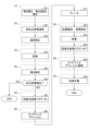
- FIG. 4 is a flowchart showing the flow of charging in the recovery charging/discharging mode. Note that the charging mode in the initial setting of this flow is the normal charging mode. In this flow, first in S11, the detection unit 10 detects the battery voltage Vb and battery temperature.
- the temporary calculation unit 21 of the calculation unit 20 calculates a temporary self-discharge rate Dst based on the detected change in battery voltage Vb.
- the correction unit 22 of the calculation unit 20 calculates the self-discharge rate Ds by correcting the temporary self-discharge rate Dst based on the battery temperature.
- the recording unit 30 stores the self-discharge rate Ds. As a result, the history of the self-discharge rate Ds is successively stored.
- the determination unit 40 calculates the slope of the self-discharge rate Ds based on the history of the self-discharge rate Ds.
- the determination unit 40 determines whether the slope is positive, that is, whether the self-discharge rate Ds is increasing. If a negative determination is made in S42, the flow is ended without switching the charging mode from the normal charging mode to the recovery charging/discharging mode, that is, while maintaining the charging mode in the normal charging mode. On the other hand, if an affirmative determination is made in S42, the process advances to S51.
- S51 the switching unit 51 of the control unit 50 turns on the recovery charge/discharge flag. This allows charging in the recovery charge/discharge mode.
- the maintenance attention unit 60 issues a maintenance attention. Note that the order of S51 and S61 may be reversed or may be performed simultaneously.
- the setting unit 52 of the control unit 50 sets the discharge current value and discharge time.
- the control unit 50 causes discharge to occur based on the set discharge current value and discharge time. Note that at this time, the charging is started by the temperature control unit 53 on the condition that the battery temperature is within a predetermined temperature range such as 20 to 25°C. Due to this discharge, most of the lithium metal layer at the negative electrode of the lithium metal battery 210 is eluted into the electrolyte.
- the switching unit 51 turns off the recovery charge/discharge flag in S54, and the maintenance attention unit 60 cancels the maintenance attention in S62.
- the control unit 50 causes charging to take longer than in the normal charging mode, that is, to perform charging at a slower speed than in the normal charging mode. This causes lithium metal to crystallize to a larger size at the negative electrode. After charging is completed, the flow ends.
- the determination unit 40 determines whether or not charging in the recovery charge/discharge mode is necessary based on the time series of the self-discharge rate Ds, rather than determining the necessity of charging in the recovery charge/discharge mode based on the magnitude of the battery voltage Vb itself or the magnitude of the self-discharge rate Ds itself. Judgment is made based on the change in. Therefore, since the object to be compared is the past self-discharge rate Ds, the determination can be made with high accuracy even when there is variation in battery voltage Vb between the lithium metal batteries 210.
- the lithium metal battery 210 has a relatively high self-discharge rate Ds when it is new, but once it is used, the self-discharge rate Ds may gradually decrease as the electrodes etc. gradually get used to it. many. However, when a slight short circuit begins to occur, the self-discharge rate Ds starts to increase. In this regard, the determination unit 40 determines that recovery charging/discharging is necessary on the condition that the self-discharge rate Ds is increasing. Therefore, the occurrence of a slight short circuit can be detected based on the fact that the self-discharge rate Ds changes from decreasing to increasing.
- the switching unit 51 allows switching from the normal charging mode to the recovery charging/discharging mode when the determining unit 40 determines that recovery charging/discharging is necessary. Therefore, it is possible to switch from the normal charging mode to the recovery charging/discharging mode only when charging in the recovery charging/discharging mode is necessary.
- the maintenance attention unit 60 issues a maintenance attention when the determination unit 40 determines that recovery charging/discharging is required. Therefore, when charging in the recovery charge/discharge mode is required, the user etc. can be notified of this fact.
- the calculation unit 20 calculates the self-discharge rate Ds at a predetermined temperature such as 25° C. and a predetermined charging state such as a fully charged state, based on the detected battery voltage Vb and the detected battery temperature. Therefore, an error in the self-discharge rate Ds caused by a difference in battery temperature can be corrected. Therefore, it is possible to more accurately determine whether or not charging in the recovery charge/discharge mode is necessary.
- the self-discharge rate Ds tends to increase due to an increase in the travel distance and operation time of the electric vehicle 200.
- the determining unit 40 determines whether or not charging in the recovery charging/discharging mode is necessary based on a change in the self-discharging rate with respect to an increase in either the traveling distance or the operating time. Therefore, the necessity of charging in the recovery charge/discharge mode can be determined more accurately than in the case where the necessity of charging in the recovery charge/discharge mode is determined based on a change in the self-discharge rate Ds with respect to a mere increase in elapsed time since the battery was new.
- the optimal discharge current value and discharge time during discharge in the recovery charge/discharge mode vary depending on the self-discharge rate Ds and battery temperature.
- the setting unit 52 sets the discharge current value and discharge time based on the self-discharge rate Ds calculated by the calculation unit, the battery temperature detected by the temperature detection unit 13, and the table 52a. Therefore, it becomes easier to set the optimal discharge current value and discharge time.
- the discharge in the recovery charge/discharge mode be performed at a predetermined temperature or higher.
- the temperature control unit 53 allows charging in the recovery charge/discharge mode on the condition that the battery temperature is equal to or higher than a predetermined temperature, so that the lithium metal battery 210 can be efficiently protected.
- the maintenance attention unit 60 issues a maintenance attention when the determination unit 40 determines that recovery charging/discharging is required, and cancels the maintenance attention when discharging in the recovery charging/discharging mode is completed. Therefore, the maintenance attention unit 60 can automatically issue and release maintenance attention.
- the determination unit 40 may determine that recovery charging/discharging is necessary at a timing that is slightly earlier or slightly later than the inflection point. That is, the determination unit 40 may determine that recovery charging/discharging is necessary, for example, on the condition that the slope of the self-discharge rate Ds is larger than a threshold value that is slightly smaller than zero or slightly larger than zero.
Landscapes
- Engineering & Computer Science (AREA)
- Manufacturing & Machinery (AREA)
- Chemical & Material Sciences (AREA)
- Chemical Kinetics & Catalysis (AREA)
- Electrochemistry (AREA)
- General Chemical & Material Sciences (AREA)
- Power Engineering (AREA)
- Secondary Cells (AREA)
- Charge And Discharge Circuits For Batteries Or The Like (AREA)
Priority Applications (3)
| Application Number | Priority Date | Filing Date | Title |
|---|---|---|---|
| CN202380026769.8A CN118922983A (zh) | 2022-03-31 | 2023-03-28 | 充电控制装置 |
| JP2024512604A JP7682380B2 (ja) | 2022-03-31 | 2023-03-28 | 充電制御装置 |
| US18/851,071 US20250219173A1 (en) | 2022-03-31 | 2023-03-28 | Charge control device |
Applications Claiming Priority (2)
| Application Number | Priority Date | Filing Date | Title |
|---|---|---|---|
| JP2022058653 | 2022-03-31 | ||
| JP2022-058653 | 2022-03-31 |
Publications (1)
| Publication Number | Publication Date |
|---|---|
| WO2023190576A1 true WO2023190576A1 (ja) | 2023-10-05 |
Family
ID=88201821
Family Applications (1)
| Application Number | Title | Priority Date | Filing Date |
|---|---|---|---|
| PCT/JP2023/012637 Ceased WO2023190576A1 (ja) | 2022-03-31 | 2023-03-28 | 充電制御装置 |
Country Status (4)
| Country | Link |
|---|---|
| US (1) | US20250219173A1 (https=) |
| JP (1) | JP7682380B2 (https=) |
| CN (1) | CN118922983A (https=) |
| WO (1) | WO2023190576A1 (https=) |
Cited By (2)
| Publication number | Priority date | Publication date | Assignee | Title |
|---|---|---|---|---|
| CN118432234A (zh) * | 2024-07-03 | 2024-08-02 | 斯普屹科技(北京)有限公司 | 配电自动化直流电源自动充放电系统 |
| JP2026064141A (ja) * | 2024-10-01 | 2026-04-13 | ソフトバンク株式会社 | 温度管理システム、温度管理方法、及びプログラム |
Families Citing this family (1)
| Publication number | Priority date | Publication date | Assignee | Title |
|---|---|---|---|---|
| CN120473590B (zh) * | 2025-07-15 | 2025-10-17 | 歌尔股份有限公司 | 一种电池保护方法、装置及电子设备 |
Citations (2)
| Publication number | Priority date | Publication date | Assignee | Title |
|---|---|---|---|---|
| JP2011165343A (ja) * | 2010-02-04 | 2011-08-25 | Hitachi Ltd | 非水電解質二次電池装置およびその負極を充電する方法 |
| JP2020205142A (ja) * | 2019-06-14 | 2020-12-24 | 株式会社Abri | リチウム二次電池 |
-
2023
- 2023-03-28 CN CN202380026769.8A patent/CN118922983A/zh active Pending
- 2023-03-28 US US18/851,071 patent/US20250219173A1/en active Pending
- 2023-03-28 WO PCT/JP2023/012637 patent/WO2023190576A1/ja not_active Ceased
- 2023-03-28 JP JP2024512604A patent/JP7682380B2/ja active Active
Patent Citations (2)
| Publication number | Priority date | Publication date | Assignee | Title |
|---|---|---|---|---|
| JP2011165343A (ja) * | 2010-02-04 | 2011-08-25 | Hitachi Ltd | 非水電解質二次電池装置およびその負極を充電する方法 |
| JP2020205142A (ja) * | 2019-06-14 | 2020-12-24 | 株式会社Abri | リチウム二次電池 |
Cited By (2)
| Publication number | Priority date | Publication date | Assignee | Title |
|---|---|---|---|---|
| CN118432234A (zh) * | 2024-07-03 | 2024-08-02 | 斯普屹科技(北京)有限公司 | 配电自动化直流电源自动充放电系统 |
| JP2026064141A (ja) * | 2024-10-01 | 2026-04-13 | ソフトバンク株式会社 | 温度管理システム、温度管理方法、及びプログラム |
Also Published As
| Publication number | Publication date |
|---|---|
| CN118922983A (zh) | 2024-11-08 |
| JP7682380B2 (ja) | 2025-05-23 |
| JPWO2023190576A1 (https=) | 2023-10-05 |
| US20250219173A1 (en) | 2025-07-03 |
Similar Documents
| Publication | Publication Date | Title |
|---|---|---|
| JP7682380B2 (ja) | 充電制御装置 | |
| CN103430371B (zh) | 恢复锂离子蓄电池容量的方法 | |
| JP5094230B2 (ja) | 非水電解質二次電池 | |
| CN105990599B (zh) | 非水电解质二次电池 | |
| JP5219422B2 (ja) | 非水電解質二次電池 | |
| KR20200105227A (ko) | 리튬 이차 전지용 전해질 및 이를 포함하는 리튬 이차 전지 | |
| JP4970056B2 (ja) | 非水電解液及びこれを用いたリチウム二次電池 | |
| JP2005521220A (ja) | 過放電防止剤を含むリチウム二次電池 | |
| US20100248022A1 (en) | Nonaqueous electrolyte secondary battery | |
| JP2004063394A (ja) | 非水電解質電池 | |
| JP6287187B2 (ja) | 非水電解質二次電池 | |
| CN104011924A (zh) | 非水电解质二次电池 | |
| JP2006512747A (ja) | 過放電性能改善用添加剤を含む正極活物質及びこれを用いたリチウム二次電池 | |
| JP2013069659A (ja) | 非水電解液二次電池 | |
| JP2010182477A (ja) | 非水電解質二次電池 | |
| JP2015125857A (ja) | 非水電解質二次電池 | |
| JP5741942B2 (ja) | リチウム二次電池の容量回復方法 | |
| JP2025100926A (ja) | 電池の劣化状態推定装置、劣化抑制システム、劣化状態推定方法、劣化抑制方法 | |
| JP2008091041A (ja) | 非水電解質二次電池 | |
| CN104704669A (zh) | 非水电解质二次电池 | |
| CN115117483A (zh) | 延长电池寿命的方法、电动设备以及存储介质 | |
| KR20200072723A (ko) | 리튬 이차전지 | |
| KR20220018216A (ko) | 다환식 설파이트/설페이트/포스파이트/포스페이트 유도체, 이를 포함하는 리튬 이차전지 전해액 및 리튬 이차전지 | |
| KR20220025311A (ko) | 전해액 첨가제, 이를 포함하는 리튬 이차전지 전해액 및 리튬 이차전지 | |
| KR20220021809A (ko) | 아세토아세트산 유도체, 이를 포함하는 리튬 이차전지 전해액 및 리튬 이차전지 |
Legal Events
| Date | Code | Title | Description |
|---|---|---|---|
| 121 | Ep: the epo has been informed by wipo that ep was designated in this application |
Ref document number: 23780585 Country of ref document: EP Kind code of ref document: A1 |
|
| ENP | Entry into the national phase |
Ref document number: 2024512604 Country of ref document: JP Kind code of ref document: A |
|
| WWE | Wipo information: entry into national phase |
Ref document number: 202380026769.8 Country of ref document: CN |
|
| WWE | Wipo information: entry into national phase |
Ref document number: 18851071 Country of ref document: US |
|
| NENP | Non-entry into the national phase |
Ref country code: DE |
|
| 122 | Ep: pct application non-entry in european phase |
Ref document number: 23780585 Country of ref document: EP Kind code of ref document: A1 |
|
| WWP | Wipo information: published in national office |
Ref document number: 18851071 Country of ref document: US |