WO2023190524A1 - 放熱板及びベイパーチャンバー - Google Patents
放熱板及びベイパーチャンバー Download PDFInfo
- Publication number
- WO2023190524A1 WO2023190524A1 PCT/JP2023/012540 JP2023012540W WO2023190524A1 WO 2023190524 A1 WO2023190524 A1 WO 2023190524A1 JP 2023012540 W JP2023012540 W JP 2023012540W WO 2023190524 A1 WO2023190524 A1 WO 2023190524A1
- Authority
- WO
- WIPO (PCT)
- Prior art keywords
- needle
- heat sink
- main surface
- bodies
- region
- Prior art date
- Legal status (The legal status is an assumption and is not a legal conclusion. Google has not performed a legal analysis and makes no representation as to the accuracy of the status listed.)
- Ceased
Links
Images





Classifications
-
- F—MECHANICAL ENGINEERING; LIGHTING; HEATING; WEAPONS; BLASTING
- F28—HEAT EXCHANGE IN GENERAL
- F28D—HEAT-EXCHANGE APPARATUS, NOT PROVIDED FOR IN ANOTHER SUBCLASS, IN WHICH THE HEAT-EXCHANGE MEDIA DO NOT COME INTO DIRECT CONTACT
- F28D15/00—Heat-exchange apparatus with the intermediate heat-transfer medium in closed tubes passing into or through the conduit walls ; Heat-exchange apparatus employing intermediate heat-transfer medium or bodies
- F28D15/02—Heat-exchange apparatus with the intermediate heat-transfer medium in closed tubes passing into or through the conduit walls ; Heat-exchange apparatus employing intermediate heat-transfer medium or bodies in which the medium condenses and evaporates, e.g. heat pipes
- F28D15/0233—Heat-exchange apparatus with the intermediate heat-transfer medium in closed tubes passing into or through the conduit walls ; Heat-exchange apparatus employing intermediate heat-transfer medium or bodies in which the medium condenses and evaporates, e.g. heat pipes the conduits having a particular shape, e.g. non-circular cross-section, annular
-
- F—MECHANICAL ENGINEERING; LIGHTING; HEATING; WEAPONS; BLASTING
- F28—HEAT EXCHANGE IN GENERAL
- F28D—HEAT-EXCHANGE APPARATUS, NOT PROVIDED FOR IN ANOTHER SUBCLASS, IN WHICH THE HEAT-EXCHANGE MEDIA DO NOT COME INTO DIRECT CONTACT
- F28D15/00—Heat-exchange apparatus with the intermediate heat-transfer medium in closed tubes passing into or through the conduit walls ; Heat-exchange apparatus employing intermediate heat-transfer medium or bodies
- F28D15/02—Heat-exchange apparatus with the intermediate heat-transfer medium in closed tubes passing into or through the conduit walls ; Heat-exchange apparatus employing intermediate heat-transfer medium or bodies in which the medium condenses and evaporates, e.g. heat pipes
- F28D15/04—Heat-exchange apparatus with the intermediate heat-transfer medium in closed tubes passing into or through the conduit walls ; Heat-exchange apparatus employing intermediate heat-transfer medium or bodies in which the medium condenses and evaporates, e.g. heat pipes with tubes having a capillary structure
- F28D15/046—Heat-exchange apparatus with the intermediate heat-transfer medium in closed tubes passing into or through the conduit walls ; Heat-exchange apparatus employing intermediate heat-transfer medium or bodies in which the medium condenses and evaporates, e.g. heat pipes with tubes having a capillary structure characterised by the material or the construction of the capillary structure
-
- H—ELECTRICITY
- H10—SEMICONDUCTOR DEVICES; ELECTRIC SOLID-STATE DEVICES NOT OTHERWISE PROVIDED FOR
- H10W—GENERIC PACKAGES, INTERCONNECTIONS, CONNECTORS OR OTHER CONSTRUCTIONAL DETAILS OF DEVICES COVERED BY CLASS H10
- H10W40/00—Arrangements for thermal protection or thermal control
- H10W40/70—Fillings or auxiliary members in containers or in encapsulations for thermal protection or control
- H10W40/73—Fillings or auxiliary members in containers or in encapsulations for thermal protection or control for cooling by change of state
Definitions
- the present disclosure relates to a heat sink and a vapor chamber.
- Patent Document 1 shows a configuration in which a wick is included in the internal space of a plate-shaped heat pipe (i.e., vapor chamber).
- An object of the present disclosure is to provide a heat sink having a structure that can maintain a liquid phase fluid (i.e., liquid) near a substrate surface at a low cost. Furthermore, it is an object of the present invention to provide a vapor chamber having the heat sink.
- the heat sink according to the present disclosure includes: a substrate having a first main surface and a second main surface located on the opposite side of the first main surface; a plurality of needle-like bodies extending outward from the first main surface of the substrate; Equipped with There is an arrangement part in which a fluid is arranged between the plurality of needle-like bodies, A portion of the substrate that includes at least a portion of the first main surface is ceramic; The needle-like body is a needle-like crystal of the ceramic.
- the vapor chamber according to the present disclosure includes: The above heat sink, a casing having an opening; a liquid phase fluid located within the housing; Equipped with the heat sink covers the opening; The plurality of needle-like bodies are located in a space surrounded by the housing and the substrate.
- FIG. 2 is an exploded perspective view showing a heat sink and a vapor chamber according to the first embodiment.
- FIG. 2 is a cross-sectional view showing a heat sink and a vapor chamber according to the first embodiment.
- FIG. 3 is a perspective view showing the back side of the heat sink of Embodiment 1. It is a perspective view showing the back side of the heat sink of a modification. It is a figure explaining a needle-like object.
- FIG. 3 is a side view illustrating a pair of needle-like bodies that intersect with each other.
- FIG. 3 is a plan view illustrating a pair of needle-like bodies that intersect with each other. It is a figure explaining the crossing of the 1st aspect of a pair of needle-like bodies which intersect with each other.
- FIG. 3 is a diagram illustrating an example of the arrangement of a pair of needle-like bodies having an intersection in a first aspect and a pair of needle-like bodies having an intersection in a second aspect, and is a diagram illustrating the flow of a gas-phase fluid and a liquid-phase fluid.
- FIG. 3 It is a figure explaining the example of arrangement
- FIG. 3 is a side view showing a plurality of needle-like bodies.
- FIG. 3 is a cross-sectional view of a needle-like body.
- FIG. 7 is a longitudinal cross-sectional view showing a heat sink and a vapor chamber according to Embodiment 2.
- FIG. 7 is a plan view showing a heat sink and a vapor chamber according to Embodiment 2.
- FIG. 7 is a vertical cross-sectional view showing a heat sink and a vapor chamber according to Embodiment 3.
- FIG. 7 is a plan view showing a heat sink and a vapor chamber according to Embodiment 3.
- FIG. 7 is a diagram showing a vapor chamber according to Embodiment 4.
- FIG. 7 is a diagram showing a vapor chamber according to Embodiment 5.
- FIG. 1A is an exploded perspective view showing a heat sink and a vapor chamber according to the first embodiment.
- FIG. 1B is a sectional view showing a heat sink and a vapor chamber according to the first embodiment.
- FIG. 2A is a perspective view showing the back side of the heat sink of Embodiment 1.
- FIG. 2B is a perspective view showing the back side of a heat sink according to a modified example.
- the needle-like bodies in FIGS. 2A and 2B are schematically shown.
- the vapor chamber 1 includes a heat sink 10 and a housing 20 having an opening E1 (see FIG. 1A).
- the housing 20 may have a space C1 such as a recess that becomes a sealed chamber when the opening E1 is closed.
- the heat sink 10 may be joined to the housing 20 so as to cover the opening E1.
- liquid phase fluid for example, water
- the heat sink 10 or the housing 20 may have one or more columnar parts 25 that support the above-mentioned space, as shown by imaginary lines in FIGS. 1A and 1B.
- the columnar portion 25 may be omitted.
- the columnar portion 25 is made of ceramic and may be integrally formed with the heat sink 10 or the housing 20. Alternatively, the columnar portion 25 may be made of metal and integrally formed with the housing 20.
- the columnar portion 25 may have a shape that is elongated in the radial direction centered on the heat source 41 (see FIG. 6A) (that is, longer than the circumferential direction centered on the heat source 41) in plan view.
- Planar perspective means seeing through from a direction perpendicular to the first principal surface S1.
- the housing 20 may be made of metal such as copper, or may be made of ceramic.
- the housing 20 may include a plate-shaped portion 21 that faces the heat sink 10 and a frame portion 22 that laterally surrounds the space within the opening E1.
- the plate portion 21 and the frame portion 22 may be integrally molded or may be joined.
- the plate portion 21 and the frame portion 22 may be made of the same material or may be made of different materials.
- one of the plate portion 21 and the frame portion 22 may be made of metal, and the other may be made of ceramic.
- the heat sink 10 may include a substrate 11 having a first main surface S1 and a second main surface S2, and a plurality of needle-like bodies 12 extending outward from the first main surface S1 of the substrate 11.
- the first principal surface S1 and the second principal surface S2 refer to two surfaces whose front area is larger than the other surfaces when the substrate 11 is viewed from multiple directions.
- the first main surface S1 and the second main surface S2 may be surfaces located on opposite sides of each other.
- Substrate 11 may be made of ceramic.
- the needle-like body 12 may be a ceramic needle-like crystal.
- the above ceramic may have a structure containing silicon nitride (Si 3 N 4 ), silicon carbide (SiC), mullite, or aluminum nitride (AlN) as a main component.
- the main component means a component having a mass ratio of 80% or more.
- the entire substrate 11 does not need to be made of ceramic, and a portion including a part of the first main surface S1 may be made of ceramic.
- the plurality of needle-shaped bodies 12 may be located in a region R2 facing the opening E1 of the housing 20 on the first main surface S1.
- the modification shown in FIG. 2B is an example in which the horizontal dimension of the board 11 is larger than the horizontal dimension of the housing 20.
- a placement portion 121 (i.e., a gap) is provided between the plurality of needle-shaped bodies 12 in which a fluid is placed. That is, when the substrate 11 exists alone, a fluid such as air may be placed in the placement portion 121. Further, when the substrate 11 is applied to the vapor chamber 1, a liquid phase fluid or a gas phase fluid may be placed in the placement portion 121.
- the needle-like body 12 can function as a wick for the vapor chamber 1.
- a wick corresponds to a structure that can hold and transport a liquid phase fluid by the surface tension of a fine linear body.
- the needle-like bodies 12 are ceramic needle-like crystals, and can be produced by a ceramic firing process. Therefore, the heat sink 10 that can hold the liquid phase fluid near the surface of the first main surface S1 can be provided at low cost.
- the arrangement portion 121 may hold a liquid phase fluid. That is, the arrangement section 121 may be called a holding section that holds the liquid phase fluid.
- the arrangement portion 121 may have the following properties for retaining a liquid phase fluid. That is, when the first main surface S1 is immersed in water and then exposed to the air with the first main surface S1 facing vertically downward, water accumulates in the gaps between the plurality of needle-shaped bodies 12 (for example, when the first main surface S1 is exposed to air on a flat surface).
- the arrangement portion 121 may have the property of accumulating 5 times or more water compared to This property can be achieved by adjusting the density and arrangement (for example, inclination, degree of variation in inclination direction, etc.) of the plurality of needle-like bodies 12. According to this property, the action of the needle-shaped body 12 as a wick can be further enhanced.
- the liquid phase fluid may be water, acetone, ammonia, etc.
- the second main surface S2 of the substrate 11 may be flatter than the region R2 where the needle-shaped body 12 is located.
- the term "flat" means that it is flat compared to the region R2 which is non-flat due to the presence of the plurality of needle-like bodies 12, and is not a comparison with the region R2 when the needle-like bodies 12 are removed.
- the above-mentioned flatness may mean that there are no needle-like crystals or that there are very short needle-like crystals.
- the second main surface S2 may be planar.
- the second main surface S2 may have a stepped portion, a convex portion, a concave portion, but the upper surface of the stepped portion, the upper surface of the convex portion, the inner bottom surface of the concave portion, etc.
- the second main surface S2 can be used as a mounting surface for an electronic element serving as a heat source.
- the second main surface S2 can be employed as the surface facing the module substrate.
- the first main surface S1 of the substrate 11 may have a bonding region R1 to which the upper surface of the frame portion 22 (i.e., the surface around the opening E1 of the housing 20) is bonded. good.
- Bonding region R1 may be annular.
- a region R2 in which the needle-shaped body 12 is located may be located inside the joint region R1 so as to be surrounded by the joint region R1.
- the joining region R1 is flatter than the region R2 where the needle-shaped body 12 is located, and may be planar.
- the flatness may mean that there are no needle-like crystals or that there are very short needle-like crystals.
- the modification shown in FIG. 2B is an example in which a joining region R1 where the housing 20 is joined and a region R2 where the needle-shaped body 12 is located are located in a part of the first main surface S1 of the heat sink 10.
- the remaining region R3 of the first principal surface S1 may have a structure in which other structures such as a conductive plate are located.
- the flatness of the second main surface S2 and the flatness of the bonding region R1 of the first main surface S1 may be achieved by polishing or blasting.
- a wick 23 may be located on the inner surface of the casing 20.
- the wick 23 may be omitted.
- the wick 23 is a sintered body formed by sintering mesh-like metal fibers, metal or ceramic particles, or a communicating hole formed by forming through holes in a plate and connecting the holes when stacking multiple layers. Good too.
- the wick 23 may be made of ceramic needle-like crystals, like the plurality of needle-like bodies 12 of the heat sink 10 .
- the vapor chamber 1 having the above structure may be used with a heat source in contact with a part of the outer surface and a cooling part such as a heat sink in contact with another part of the outer surface.
- the liquid-phase fluid e.g., water
- a gas-phase fluid e.g., steam
- the vaporized gas-phase fluid is cooled in the cooling section to become a liquid phase.
- Condenses into a fluid e.g. water).
- the gas-phase fluid and the liquid-phase fluid circulate within the space C1 while undergoing the phase change, thereby realizing high heat conduction from the heat source to the cooling section.
- the needle-shaped body 12 and the wick 23 attract the liquid phase fluid due to surface tension. Therefore, the liquid phase fluid tends to flow near the first main surface S1 where the plurality of needle-shaped bodies 12 are located and near the inner surface of the casing 20 where the wick 23 is located.
- the gas-phase fluid tends to flow in an open space away from the needle-shaped body 12 and the wick 23. Due to this action, the gas-phase fluid flows in a space away from the first main surface S1 and the inner surface of the housing 20, and the liquid-phase fluid flows in the vicinity of the first main surface S1 and in the vicinity of the inner surface of the space C1. A closed circuit is formed, and smooth circulation of gas-phase fluid and liquid-phase fluid is realized.
- FIG. 3 is a diagram illustrating the needle-like body.
- the plurality of needle-like bodies 12 may include a first needle-like body 12a that is inclined at an angle ⁇ of more than 50 degrees with respect to the perpendicular to the first main surface S1.
- the needle-shaped bodies 12 having such an inclination may be included in a number of 40% or more. According to this configuration, a minute gap is created between the first needle-shaped body 12a and the first main surface S1, and the ability to draw liquid into the gap based on surface tension is obtained. Therefore, the plurality of needle-like bodies 12 can make the vapor chamber 1 more effective as a wick.
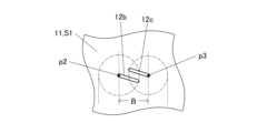
- FIGS. 4A and 4B are diagrams illustrating a pair of needle-like bodies that intersect with each other, with FIG. 4A being a side view and FIG. 4B being a plan view.
- the plurality of needle-like bodies 12 include a second needle-like body 12b and a third needle-like body 12c that are adjacent to each other, and the second needle-like bodies 12b and the third needle-like body 12c cross each other when viewed from the side.
- the formula (1) may also be satisfied.
- A2 is the length of the second needle-like body 12b
- A3 is the length of the third needle-like body 12c
- B is the length of the third needle-like body 12c from the root p2 of the second needle-like body 12b. This is the distance to the root p3.
- Length means the straight-line distance from the root to the tip.
- Viewing from the side means viewing from the direction along the first principal surface S1, and the side may be a direction perpendicular to the line segment connecting the roots p2 and p3.
- the root of the needle-like body means the boundary between the first main surface S1 and the needle-like body.
- the plurality of needle-like bodies 12 may include a pair of intersecting needle-like bodies 12 in a number of 50% or more.
- the pair of intersecting needle-like bodies 12 creates a fine space between the pair of needle-like bodies 12, and a high ability to draw liquid into the space based on surface tension is obtained. Therefore, the plurality of needle-shaped bodies 12 can make the vapor chamber 1 more effective as a wick.
- FIG. 5A is a diagram illustrating the first mode of intersection of a pair of needle-shaped bodies that intersect with each other.
- FIG. 5B is a diagram illustrating the second mode of intersection of a pair of needle-like bodies that intersect with each other.
- the intersection p1 of the second needle-like body 12b and the third needle-like body 12c, the root p2 of the second needle-like body 12b, and the root p3 of the third needle-like body 12c are defined as three vertices.
- the area D2 of the triangle on the tip side whose three vertices are the intersection p1, the tip p12 of the second needle-like body 12b, and the tip p13 of the third needle-like body 12c is larger than the area D1 of the triangle on the base side. may be smaller (see FIG. 5A). This mode of intersection is called the first mode.
- more liquid can be held near the surface of the first main surface S1, so that the effect of transporting more liquid phase fluid in the vapor chamber 1 is obtained, and the heat of the vapor chamber 1 is increased.
- Transport volume can be improved.
- the intersection p1 of the second needle-like body 12b and the third needle-like body 12c, the root p2 of the second needle-like body 12b, and the root p3 of the third needle-like body 12c are defined as three vertices.
- the area D2 of the triangle on the tip side whose three vertices are the intersection p1, the tip p12 of the second needle-like body 12b, and the tip p13 of the third needle-like body 12c is larger than the area D1 of the triangle on the base side. may be larger (see FIG. 5B). This mode of intersection is called the second mode.
- surface tension produces an effect of drawing the liquid more toward the surface side of the first main surface S1, so when the liquid phase fluid circulates in the vapor chamber 1, the liquid is drawn onto the first main surface S1.
- the thickness of the liquid phase fluid can be reduced. Therefore, the thermal resistance due to the film-like liquid phase fluid can be reduced.
- FIGS. 6A and 6B are diagrams illustrating an example of the arrangement of a pair of needle-like bodies having an intersection in the first mode and a pair of needle-like bodies having an intersection in the second mode
- FIG. FIG. 6B which is a diagram explaining the flow of the liquid phase fluid, is a diagram showing the arrangement area on the first main surface.
- white arrows indicate the flow of gas-phase fluid
- shaded arrows indicate the flow of liquid-phase fluid.
- regions R31 and R32 are indicated by hatching.
- the needle-shaped body 12 having the first aspect of intersection is located in the first principal surface S1 in a region R32 near the edge (see FIG. 6B). A large amount may be included in the central region R31 (see FIG. 6B) of one main surface S1. On the other hand, the needle-like bodies 12 having the second aspect of intersection are more concentrated in the region R32 near the edge of the first main surface S1 (see FIG. 6B) than in the region R31 in the center of the first main surface S1 (see FIG. 6B). ) may be included in large amounts.
- the efficiency of heat exchange can be improved as follows. That is, as shown in FIG. 6A, when the heat source 41 is located at the center of the second main surface S2 or the center of the plate-shaped portion 21 of the housing 20, the region R31 of the first main surface S1 near the heat source 41 Vaporization of the liquid phase fluid occurs frequently. On the other hand, a large amount of gaseous fluid condenses in the region R32 near the edge of the first principal surface S1. If there are many needle-like bodies 12 having the first aspect of intersection (see FIG. 5A), a large amount of liquid phase fluid can be held near the first main surface S1. Therefore, it is desirable that the needle-like bodies 12 having the first aspect of intersection (see FIG.
- FIG. 7A is a side view showing a plurality of needle-like bodies.
- FIG. 7B is a cross-sectional view of the needle-like body.
- the plurality of needle-like bodies 12 has a gap v1 in a region from half the maximum height occupied by the needle-like bodies 12 to the first main surface S1 when viewed from the side.
- the area may be smaller than the area of the gap v2 in the region opposite to the first principal surface S1 from half the height.
- the areas of the gaps v1 and v2 are determined by slicing the heat dissipation plate 10 having the plurality of needle-like bodies 12 to a predetermined thickness (for example, 5 mm) so that the cut surface is perpendicular to the first main surface S1, and This can be confirmed by measuring the range in which the other side of the plurality of needle-like bodies 12 can be seen from a position facing the slice plane.
- the effect of drawing the liquid phase fluid by surface tension is greater on the root side closer to the first main surface S1 than on the tip side farther from the first main surface S1 in the plurality of needle-like bodies 12. Since the gas phase fluid flows in a space away from the first principal surface S1, the above configuration causes the liquid phase flow and the gas phase flow to collide at the interface between the gas phase fluid flow and the liquid phase fluid flow. It is possible to reduce the turbulence of fluid reflux that occurs. Therefore, smooth circulation of the gas phase fluid and liquid phase fluid within the space C1 (see FIG. 1B) can be realized, and the efficiency of heat exchange can be improved.
- the plurality of needle-shaped bodies 12 may have a polygonal cross section as shown in FIG. 7B.
- the needle-like bodies 12 have the function of transmitting heat applied from outside the heat sink 10 to the fluid (that is, liquid phase fluid and gas phase fluid), or the function of transmitting the heat of the fluid to the outside of the heat sink 10. take charge With the above configuration, the surface area of the needle-shaped body 12 can be increased relative to its volume. Therefore, the efficiency of heat exchange between the needle-shaped body 12 and the fluid can be improved.
- FIG. 8A is a longitudinal cross-sectional view showing a heat sink and a vapor chamber according to the second embodiment.
- FIG. 8B is a plan view showing a heat sink and a vapor chamber according to the second embodiment.
- the heat sink 10A of the second embodiment includes a conductor plate 13 located on the second main surface S2 of the substrate 11.
- the other configuration of the heat sink 10A may be the same as that of the heat sink 10 of the first embodiment.
- the conductor plate 13 may be located at the center of the second main surface S2 or may be located off the center.
- the upper surface of the conductor plate 13 may be a mounting portion for mounting a heat source 41 (for example, an electronic device, etc.).
- the conductor plate 13 is a metallized conductor, and may be hardened during and after firing the heat dissipation plate 10A, or may be formed by vacuum film formation, wet plating, etc. after firing.
- the main component of the conductive plate 13 may be copper.
- the conductor plate 13 may have multiple electrodes.
- the heat sink 10A has a wiring conductor (not shown) extending from a plurality of electrodes (for example, the conductor plate 13) along the outer surface of the substrate 11, and connects a heat source 41 (for example, an electronic device, etc.) via the wiring conductor and the conductor plate 13.
- the structure may be such that at least one of an electrical signal and a power supply voltage is transmitted to the terminal.
- 10 A of heat sinks which have at least one of an electrode and a wiring conductor may be called a circuit board.
- the vapor chamber 1A of the second embodiment is the same as the vapor chamber 1 of the first embodiment except for the conductor plate 13 of the heat sink 10A.
- the heat sink 10A of the second embodiment heat is conducted from the heat source 41 to the heat sink 10A via the conductor plate 13, so that the thermal conductivity to the heat sink 10A can be improved.
- the heat source 41 is arranged not on the side of the housing 20 but on the side of the heat sink 10A having a plurality of needle-shaped bodies 12. . Therefore, the liquid phase fluid can be caused to flow toward the heat supply side by the plurality of needle-like bodies 12 acting as wicks. Therefore, the heat exchange efficiency of the vapor chamber 1A can be improved.
- FIG. 9A is a longitudinal cross-sectional view showing a heat sink and a vapor chamber according to Embodiment 3.
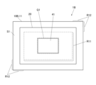
- FIG. 9B is a plan view showing a heat sink and a vapor chamber according to the third embodiment.
- the heat sink 10B of the third embodiment is the same as the heat sink 10 of the first embodiment except that the configuration of the first main surface S1 is different.
- the first main surface S1 of the heat dissipation plate 10B has a first region R11 where a plurality of needle-shaped bodies 12 are located, and a second region R12 that is flatter than the first region R11, and the second region R12 has a first region R12 that is flatter than the first region R11.
- a second region R12 surrounding the region R11 may have a larger area than the first region R11.
- “Flat” may mean that there are no needle-like crystals, or that there are very short needle-like crystals, or it may mean that it is planar.
- the second region R12 of the first main surface S1 is connected to the outside along with the casing 20. It is possible to configure a vapor chamber 1B exposed to Since the exposed portion of the first principal surface S1 is flat, it is possible to mount other components on the portion, or to hold the portion for gripping or fixing. is obtained.
- At least one of an electrode and a wiring conductor may be located on the exposed portion of the first main surface S1, inside the insulating portion of the substrate 11, and on the second main surface S2.
- the heat sink 10B having at least one of an electrode and a wiring conductor may be called a circuit board.
- the housing 20 may have the configuration described in the first embodiment.
- the heat source 41 may be arranged on the housing 20 side instead of on the heat sink 10B side. That is, the mounting portion Q1 (see FIG. 9B) of the heat source 41 may be located on the surface of the plate-like portion 21 of the casing 20 opposite to the heat sink 10B.
- condensation of the gaseous fluid can be promoted by absorbing heat from the tip side of the plurality of needle-like bodies 12. Further, the liquid phase fluid drawn near the first main surface S1 by the plurality of needles 12 spreads to the region of the first main surface S1 where the needles 12 are located, thereby becoming thinner. Therefore, the thermal resistance due to the film-like liquid phase fluid can be reduced.
- FIG. 10A shows a vapor chamber according to Embodiment 4.
- FIG. 10B is a diagram showing a vapor chamber according to Embodiment 5.
- the vapor chamber 1C (see FIG. 10A) according to the fourth embodiment is an example in which the plate-shaped portion 21 of the housing 20 is configured in the same manner as the heat sink 10 of the first embodiment, and the other parts are the same as the vapor chamber of the first embodiment. It is the same as 1.
- the first main surface S1 of the heat sink 10, which is the plate-like part 21, is located so as to face the internal space C1
- the plurality of needles located on the first main surface S1 of the heat sink 10, which is the plate-like part 21, are located so as to face the internal space C1 side.
- the shaped body 12 is located in the internal space C1.
- the plurality of needle-shaped bodies 12 of the pair of opposing heat sinks 10 act as wicks, and highly efficient heat exchange can be achieved.
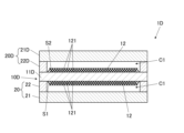
- the heat dissipation plate 10D includes a substrate 11D in which a plurality of needle-like bodies 12 are located on the first main surface S1 and the second main surface S2.
- the second main surface S2 of the substrate 11D may have the same configuration as the first main surface S1 of the heat sink 10 of the first embodiment.
- the housing 20D is also bonded to the second main surface S2 of the substrate 11D.
- the housing 20D has a plate-like portion 21D and a frame portion 22D.
- the housing 20D may be configured similarly to the housing 20 of the first embodiment.
- the other configurations are the same as the vapor chamber 1 of the first embodiment.
- the plurality of needle-like bodies 12 on the first main surface S1 and the plurality of needle-like bodies 12 on the second main surface S2 act as a wick, making it possible to realize highly efficient heat exchange.
- the heat sink and vapor chamber of the present disclosure are not limited to the above embodiments.
- the space inside the vapor chamber may be a space that spreads out in a plate shape, or may be a space that extends in a bar shape.
- the heat sink may be configured to surround at least a portion of the space.
- Other details shown in the embodiments can be changed as appropriate without departing from the spirit of the invention.
- the present disclosure can be used for heat sinks and vapor chambers.
Landscapes
- Engineering & Computer Science (AREA)
- Life Sciences & Earth Sciences (AREA)
- Sustainable Development (AREA)
- Physics & Mathematics (AREA)
- Thermal Sciences (AREA)
- Mechanical Engineering (AREA)
- General Engineering & Computer Science (AREA)
- Cooling Or The Like Of Semiconductors Or Solid State Devices (AREA)
- Cooling Or The Like Of Electrical Apparatus (AREA)
Priority Applications (4)
| Application Number | Priority Date | Filing Date | Title |
|---|---|---|---|
| CN202380029917.1A CN118922681A (zh) | 2022-03-30 | 2023-03-28 | 散热板及均热板 |
| US18/853,008 US20250224181A1 (en) | 2022-03-30 | 2023-03-28 | Heat dissipation plate and vapor chamber |
| JP2024512571A JPWO2023190524A1 (https=) | 2022-03-30 | 2023-03-28 | |
| EP23780533.8A EP4502522A1 (en) | 2022-03-30 | 2023-03-28 | Heat dissipation plate and vapor chamber |
Applications Claiming Priority (2)
| Application Number | Priority Date | Filing Date | Title |
|---|---|---|---|
| JP2022-055454 | 2022-03-30 | ||
| JP2022055454 | 2022-03-30 |
Publications (1)
| Publication Number | Publication Date |
|---|---|
| WO2023190524A1 true WO2023190524A1 (ja) | 2023-10-05 |
Family
ID=88202585
Family Applications (1)
| Application Number | Title | Priority Date | Filing Date |
|---|---|---|---|
| PCT/JP2023/012540 Ceased WO2023190524A1 (ja) | 2022-03-30 | 2023-03-28 | 放熱板及びベイパーチャンバー |
Country Status (5)
| Country | Link |
|---|---|
| US (1) | US20250224181A1 (https=) |
| EP (1) | EP4502522A1 (https=) |
| JP (1) | JPWO2023190524A1 (https=) |
| CN (1) | CN118922681A (https=) |
| WO (1) | WO2023190524A1 (https=) |
Cited By (1)
| Publication number | Priority date | Publication date | Assignee | Title |
|---|---|---|---|---|
| WO2025244030A1 (ja) * | 2024-05-21 | 2025-11-27 | 京セラ株式会社 | 放熱部材、ベイパーチャンバー及び機能モジュール |
Citations (5)
| Publication number | Priority date | Publication date | Assignee | Title |
|---|---|---|---|---|
| JPS5050411A (https=) * | 1973-09-05 | 1975-05-06 | ||
| JP2000150739A (ja) * | 1998-11-05 | 2000-05-30 | Electrovac Fabrikation Elektrotechnischer Spezialartikel Gmbh | 電気デバイスおよび/または電子デバイス用のヒ―トシンク |
| JP2003254685A (ja) | 2001-10-01 | 2003-09-10 | Furukawa Electric Co Ltd:The | 板型ヒートパイプおよびその製造方法 |
| JP2009260168A (ja) * | 2008-04-21 | 2009-11-05 | Sumitomo Electric Ind Ltd | 放熱構造、放熱装置及び放熱構造の製造方法 |
| JP2010151354A (ja) * | 2008-12-24 | 2010-07-08 | Sony Corp | 熱輸送デバイス及び電子機器 |
Family Cites Families (9)
| Publication number | Priority date | Publication date | Assignee | Title |
|---|---|---|---|---|
| JP2002141449A (ja) * | 2000-10-31 | 2002-05-17 | Denso Corp | 沸騰冷却器 |
| US7579077B2 (en) * | 2003-05-05 | 2009-08-25 | Nanosys, Inc. | Nanofiber surfaces for use in enhanced surface area applications |
| US20110108245A1 (en) * | 2009-11-10 | 2011-05-12 | Dsem Holdings Sdn. Bhd. | Circuit Board Forming Diffusion Bonded Wall of Vapor Chamber |
| CN103649240B (zh) * | 2011-01-19 | 2016-09-14 | 哈佛学院院长等 | 具有高压稳定性、光学透明性以及自修复特征的光滑表面 |
| US20130126132A1 (en) * | 2011-11-18 | 2013-05-23 | Chih-peng Chen | Vapor chamber with integrally formed wick structure and method of manufacturing same |
| CN108323137A (zh) * | 2017-01-18 | 2018-07-24 | 台达电子工业股份有限公司 | 均热板 |
| US10473404B2 (en) * | 2017-11-14 | 2019-11-12 | Asia Vital Components Co., Ltd. | Straight-through structure of heat dissipation unit |
| US20190285357A1 (en) * | 2018-03-19 | 2019-09-19 | Asia Vital Components Co., Ltd. | Middle member of heat dissipation device and the heat dissipation device |
| WO2021188128A1 (en) * | 2020-03-18 | 2021-09-23 | Kelvin Thermal Technologies, Inc. | Deformed mesh thermal ground plane |
-
2023
- 2023-03-28 EP EP23780533.8A patent/EP4502522A1/en not_active Withdrawn
- 2023-03-28 WO PCT/JP2023/012540 patent/WO2023190524A1/ja not_active Ceased
- 2023-03-28 US US18/853,008 patent/US20250224181A1/en active Pending
- 2023-03-28 CN CN202380029917.1A patent/CN118922681A/zh active Pending
- 2023-03-28 JP JP2024512571A patent/JPWO2023190524A1/ja active Pending
Patent Citations (5)
| Publication number | Priority date | Publication date | Assignee | Title |
|---|---|---|---|---|
| JPS5050411A (https=) * | 1973-09-05 | 1975-05-06 | ||
| JP2000150739A (ja) * | 1998-11-05 | 2000-05-30 | Electrovac Fabrikation Elektrotechnischer Spezialartikel Gmbh | 電気デバイスおよび/または電子デバイス用のヒ―トシンク |
| JP2003254685A (ja) | 2001-10-01 | 2003-09-10 | Furukawa Electric Co Ltd:The | 板型ヒートパイプおよびその製造方法 |
| JP2009260168A (ja) * | 2008-04-21 | 2009-11-05 | Sumitomo Electric Ind Ltd | 放熱構造、放熱装置及び放熱構造の製造方法 |
| JP2010151354A (ja) * | 2008-12-24 | 2010-07-08 | Sony Corp | 熱輸送デバイス及び電子機器 |
Cited By (1)
| Publication number | Priority date | Publication date | Assignee | Title |
|---|---|---|---|---|
| WO2025244030A1 (ja) * | 2024-05-21 | 2025-11-27 | 京セラ株式会社 | 放熱部材、ベイパーチャンバー及び機能モジュール |
Also Published As
| Publication number | Publication date |
|---|---|
| JPWO2023190524A1 (https=) | 2023-10-05 |
| EP4502522A1 (en) | 2025-02-05 |
| CN118922681A (zh) | 2024-11-08 |
| US20250224181A1 (en) | 2025-07-10 |
Similar Documents
| Publication | Publication Date | Title |
|---|---|---|
| JP7023298B2 (ja) | 電力変換装置及び電力変換装置の製造方法 | |
| JP5537736B2 (ja) | 半導体素子収納用パッケージ、これを備えた半導体装置および電子装置 | |
| CN110809910B (zh) | 功率模块用基板以及功率模块 | |
| US10959357B2 (en) | Circuit block assembly | |
| KR20090004738A (ko) | 반도체 패키지용 방열 플레이트 및 반도체 장치 | |
| US20200144223A1 (en) | Structure of electronic device | |
| JP7622410B2 (ja) | 冷却器及び半導体装置 | |
| TW201138028A (en) | Package for housing semiconductor element and semiconductor device using the same | |
| WO2021124704A1 (ja) | 半導体装置 | |
| WO2023190524A1 (ja) | 放熱板及びベイパーチャンバー | |
| CN105451512A (zh) | 散热器 | |
| TW201427583A (zh) | 散熱裝置 | |
| WO2021245983A1 (ja) | 車載電子制御装置 | |
| JP2021158190A (ja) | 電子機器及びベーパーチャンバー | |
| KR20200142264A (ko) | 방열부재를 포함하는 인쇄회로기판 어셈블리 | |
| WO2015097833A1 (ja) | 電力変換装置 | |
| WO2024019108A1 (ja) | 放熱基板及びベイパーチャンバー | |
| CN117276211A (zh) | 半导体装置和半导体装置的制造方法 | |
| CN101641784B (zh) | 表面贴装器件及其制造方法 | |
| CN113903714A (zh) | 半导体装置 | |
| US20250392096A1 (en) | Substrate, electronic device, electronic module, and module device | |
| CN116325128B (zh) | 半导体装置 | |
| US20250254829A1 (en) | Vapor chamber | |
| JP7494138B2 (ja) | 電子制御装置 | |
| WO2025244030A1 (ja) | 放熱部材、ベイパーチャンバー及び機能モジュール |
Legal Events
| Date | Code | Title | Description |
|---|---|---|---|
| 121 | Ep: the epo has been informed by wipo that ep was designated in this application |
Ref document number: 23780533 Country of ref document: EP Kind code of ref document: A1 |
|
| ENP | Entry into the national phase |
Ref document number: 2024512571 Country of ref document: JP Kind code of ref document: A |
|
| WWE | Wipo information: entry into national phase |
Ref document number: 202380029917.1 Country of ref document: CN |
|
| WWE | Wipo information: entry into national phase |
Ref document number: 18853008 Country of ref document: US |
|
| WWE | Wipo information: entry into national phase |
Ref document number: 2023780533 Country of ref document: EP |
|
| NENP | Non-entry into the national phase |
Ref country code: DE |
|
| ENP | Entry into the national phase |
Ref document number: 2023780533 Country of ref document: EP Effective date: 20241030 |
|
| WWP | Wipo information: published in national office |
Ref document number: 18853008 Country of ref document: US |
|
| WWW | Wipo information: withdrawn in national office |
Ref document number: 2023780533 Country of ref document: EP |