WO2023190388A1 - 作業機械 - Google Patents
作業機械 Download PDFInfo
- Publication number
- WO2023190388A1 WO2023190388A1 PCT/JP2023/012298 JP2023012298W WO2023190388A1 WO 2023190388 A1 WO2023190388 A1 WO 2023190388A1 JP 2023012298 W JP2023012298 W JP 2023012298W WO 2023190388 A1 WO2023190388 A1 WO 2023190388A1
- Authority
- WO
- WIPO (PCT)
- Prior art keywords
- arm
- bucket
- height
- interference prevention
- angle
- Prior art date
- Legal status (The legal status is an assumption and is not a legal conclusion. Google has not performed a legal analysis and makes no representation as to the accuracy of the status listed.)
- Ceased
Links
Images


Classifications
-
- E—FIXED CONSTRUCTIONS
- E02—HYDRAULIC ENGINEERING; FOUNDATIONS; SOIL SHIFTING
- E02F—DREDGING; SOIL-SHIFTING
- E02F3/00—Dredgers; Soil-shifting machines
- E02F3/04—Dredgers; Soil-shifting machines mechanically-driven
- E02F3/28—Dredgers; Soil-shifting machines mechanically-driven with digging tools mounted on a dipper- or bucket-arm, i.e. there is either one arm or a pair of arms, e.g. dippers, buckets
- E02F3/36—Component parts
- E02F3/42—Drives for dippers, buckets, dipper-arms or bucket-arms
- E02F3/43—Control of dipper or bucket position; Control of sequence of drive operations
- E02F3/435—Control of dipper or bucket position; Control of sequence of drive operations for dipper-arms, backhoes or the like
- E02F3/437—Control of dipper or bucket position; Control of sequence of drive operations for dipper-arms, backhoes or the like providing automatic sequences of movements, e.g. linear excavation, keeping dipper angle constant
-
- E—FIXED CONSTRUCTIONS
- E02—HYDRAULIC ENGINEERING; FOUNDATIONS; SOIL SHIFTING
- E02F—DREDGING; SOIL-SHIFTING
- E02F3/00—Dredgers; Soil-shifting machines
- E02F3/04—Dredgers; Soil-shifting machines mechanically-driven
- E02F3/28—Dredgers; Soil-shifting machines mechanically-driven with digging tools mounted on a dipper- or bucket-arm, i.e. there is either one arm or a pair of arms, e.g. dippers, buckets
- E02F3/30—Dredgers; Soil-shifting machines mechanically-driven with digging tools mounted on a dipper- or bucket-arm, i.e. there is either one arm or a pair of arms, e.g. dippers, buckets with a dipper-arm pivoted on a cantilever beam, i.e. boom
- E02F3/32—Dredgers; Soil-shifting machines mechanically-driven with digging tools mounted on a dipper- or bucket-arm, i.e. there is either one arm or a pair of arms, e.g. dippers, buckets with a dipper-arm pivoted on a cantilever beam, i.e. boom working downwardly and towards the machine, e.g. with backhoes
-
- E—FIXED CONSTRUCTIONS
- E02—HYDRAULIC ENGINEERING; FOUNDATIONS; SOIL SHIFTING
- E02F—DREDGING; SOIL-SHIFTING
- E02F3/00—Dredgers; Soil-shifting machines
- E02F3/04—Dredgers; Soil-shifting machines mechanically-driven
- E02F3/28—Dredgers; Soil-shifting machines mechanically-driven with digging tools mounted on a dipper- or bucket-arm, i.e. there is either one arm or a pair of arms, e.g. dippers, buckets
- E02F3/36—Component parts
- E02F3/42—Drives for dippers, buckets, dipper-arms or bucket-arms
- E02F3/43—Control of dipper or bucket position; Control of sequence of drive operations
- E02F3/435—Control of dipper or bucket position; Control of sequence of drive operations for dipper-arms, backhoes or the like
- E02F3/439—Automatic repositioning of the implement, e.g. automatic dumping, auto-return
-
- E—FIXED CONSTRUCTIONS
- E02—HYDRAULIC ENGINEERING; FOUNDATIONS; SOIL SHIFTING
- E02F—DREDGING; SOIL-SHIFTING
- E02F9/00—Component parts of dredgers or soil-shifting machines, not restricted to one of the kinds covered by groups E02F3/00 - E02F7/00
- E02F9/08—Superstructures; Supports for superstructures
- E02F9/10—Supports for movable superstructures mounted on travelling or walking gears or on other superstructures
- E02F9/12—Slewing or traversing gears
- E02F9/121—Turntables, i.e. structure rotatable about 360°
- E02F9/123—Drives or control devices specially adapted therefor
-
- E—FIXED CONSTRUCTIONS
- E02—HYDRAULIC ENGINEERING; FOUNDATIONS; SOIL SHIFTING
- E02F—DREDGING; SOIL-SHIFTING
- E02F9/00—Component parts of dredgers or soil-shifting machines, not restricted to one of the kinds covered by groups E02F3/00 - E02F7/00
- E02F9/20—Drives; Control devices
- E02F9/2025—Particular purposes of control systems not otherwise provided for
- E02F9/2033—Limiting the movement of frames or implements, e.g. to avoid collision between implements and the cabin
-
- E—FIXED CONSTRUCTIONS
- E02—HYDRAULIC ENGINEERING; FOUNDATIONS; SOIL SHIFTING
- E02F—DREDGING; SOIL-SHIFTING
- E02F9/00—Component parts of dredgers or soil-shifting machines, not restricted to one of the kinds covered by groups E02F3/00 - E02F7/00
- E02F9/20—Drives; Control devices
- E02F9/2025—Particular purposes of control systems not otherwise provided for
- E02F9/2037—Coordinating the movements of the implement and of the frame
-
- E—FIXED CONSTRUCTIONS
- E02—HYDRAULIC ENGINEERING; FOUNDATIONS; SOIL SHIFTING
- E02F—DREDGING; SOIL-SHIFTING
- E02F9/00—Component parts of dredgers or soil-shifting machines, not restricted to one of the kinds covered by groups E02F3/00 - E02F7/00
- E02F9/20—Drives; Control devices
- E02F9/22—Hydraulic or pneumatic drives
-
- E—FIXED CONSTRUCTIONS
- E02—HYDRAULIC ENGINEERING; FOUNDATIONS; SOIL SHIFTING
- E02F—DREDGING; SOIL-SHIFTING
- E02F9/00—Component parts of dredgers or soil-shifting machines, not restricted to one of the kinds covered by groups E02F3/00 - E02F7/00
- E02F9/24—Safety devices, e.g. for preventing overload
-
- E—FIXED CONSTRUCTIONS
- E02—HYDRAULIC ENGINEERING; FOUNDATIONS; SOIL SHIFTING
- E02F—DREDGING; SOIL-SHIFTING
- E02F9/00—Component parts of dredgers or soil-shifting machines, not restricted to one of the kinds covered by groups E02F3/00 - E02F7/00
- E02F9/26—Indicating devices
-
- E—FIXED CONSTRUCTIONS
- E02—HYDRAULIC ENGINEERING; FOUNDATIONS; SOIL SHIFTING
- E02F—DREDGING; SOIL-SHIFTING
- E02F9/00—Component parts of dredgers or soil-shifting machines, not restricted to one of the kinds covered by groups E02F3/00 - E02F7/00
- E02F9/26—Indicating devices
- E02F9/261—Surveying the work-site to be treated
- E02F9/262—Surveying the work-site to be treated with follow-up actions to control the work tool, e.g. controller
-
- E—FIXED CONSTRUCTIONS
- E02—HYDRAULIC ENGINEERING; FOUNDATIONS; SOIL SHIFTING
- E02F—DREDGING; SOIL-SHIFTING
- E02F9/00—Component parts of dredgers or soil-shifting machines, not restricted to one of the kinds covered by groups E02F3/00 - E02F7/00
- E02F9/26—Indicating devices
- E02F9/264—Sensors and their calibration for indicating the position of the work tool
- E02F9/265—Sensors and their calibration for indicating the position of the work tool with follow-up actions (e.g. control signals sent to actuate the work tool)
-
- B—PERFORMING OPERATIONS; TRANSPORTING
- B60—VEHICLES IN GENERAL
- B60Y—INDEXING SCHEME RELATING TO ASPECTS CROSS-CUTTING VEHICLE TECHNOLOGY
- B60Y2200/00—Type of vehicle
- B60Y2200/40—Special vehicles
- B60Y2200/41—Construction vehicles, e.g. graders, excavators
- B60Y2200/412—Excavators
-
- E—FIXED CONSTRUCTIONS
- E02—HYDRAULIC ENGINEERING; FOUNDATIONS; SOIL SHIFTING
- E02F—DREDGING; SOIL-SHIFTING
- E02F9/00—Component parts of dredgers or soil-shifting machines, not restricted to one of the kinds covered by groups E02F3/00 - E02F7/00
- E02F9/20—Drives; Control devices
- E02F9/22—Hydraulic or pneumatic drives
- E02F9/2203—Arrangements for controlling the attitude of actuators, e.g. speed, floating function
-
- E—FIXED CONSTRUCTIONS
- E02—HYDRAULIC ENGINEERING; FOUNDATIONS; SOIL SHIFTING
- E02F—DREDGING; SOIL-SHIFTING
- E02F9/00—Component parts of dredgers or soil-shifting machines, not restricted to one of the kinds covered by groups E02F3/00 - E02F7/00
- E02F9/20—Drives; Control devices
- E02F9/22—Hydraulic or pneumatic drives
- E02F9/2278—Hydraulic circuits
- E02F9/2285—Pilot-operated systems
-
- E—FIXED CONSTRUCTIONS
- E02—HYDRAULIC ENGINEERING; FOUNDATIONS; SOIL SHIFTING
- E02F—DREDGING; SOIL-SHIFTING
- E02F9/00—Component parts of dredgers or soil-shifting machines, not restricted to one of the kinds covered by groups E02F3/00 - E02F7/00
- E02F9/20—Drives; Control devices
- E02F9/22—Hydraulic or pneumatic drives
- E02F9/2278—Hydraulic circuits
- E02F9/2292—Systems with two or more pumps
Definitions
- the present invention relates to working machines.
- a working machine such as a hydraulic excavator, is known that includes a rotating body that is rotatably attached to a traveling body and an articulated working device that is attached to the rotating body.
- a working device installed on a hydraulic excavator or the like includes a boom rotatably attached to a revolving body, an arm rotatably attached to the boom, and a bucket rotatably attached to the arm.
- Hydraulic excavators have two functions: a transport operation in which excavated material such as earth and sand excavated by a working device is transported above the loading platform (vessel) of a loaded machine such as a dump truck, and a discharge operation in which the excavated material is discharged onto the loading platform of a dump truck. , and carry out the loading work of the excavated materials.
- Patent Document 1 discloses a hydraulic excavator equipped with a control device that can perform control to prevent a bucket from coming into contact with a dump truck due to rotation of a revolving structure.
- the control device for a hydraulic excavator described in Patent Document 1 specifies a discharge position based on position information and azimuth information of a dump truck, and specifies an interference avoidance position based on the specified discharge position.
- the control device described in Patent Document 1 has a height equal to the discharge position (unloading position), a distance from the rotation center of the revolving body equal to the distance from the rotation center to the discharge position, and a dumping position below the bucket.
- An interference avoidance position where no truck exists is specified, and after the bucket reaches the interference avoidance position, an operation signal is generated to drive only the revolving structure.
- a hydraulic excavator operator may adjust the attitude of the work equipment when the bucket is located near the loading platform. For example, in a loading operation, a suitable position for discharging the excavated material from the bucket to the dump truck differs depending on the situation of the excavated material discharged to the dump truck. Therefore, during loading work, the operator of the hydraulic excavator may adjust the attitude of the working device so that the bucket reaches a desired discharge position after the bucket is located above the dump truck.
- control device for a hydraulic excavator described in Patent Document 1 operates only the rotating body when moving the bucket from the interference avoidance position to the release position.
- the technology described in Patent Document 1 after the bucket approaches the loading platform of the dump truck, it is not possible to operate the working device to reflect the operator's intention and adjust the discharge position, which may give the operator a sense of discomfort. be.
- the present invention is a working machine that can prevent interference between a working device and a vessel of a loaded machine during loading work, etc., and that reflects the operator's intention after the working device approaches the side of the vessel.
- An object of the present invention is to provide a working machine in which the posture of a working device can be adjusted.
- a working machine includes a traveling body, a revolving body that is rotatably provided with respect to the traveling body, a working device that is attached to the rotating body and has a boom, an arm, and a bucket, and the working device.
- a posture detection device for detecting the posture of the machine
- a vessel position acquisition device for acquiring the position of a vessel of a loaded machine into which excavated material excavated by the work device is loaded
- an arm operation device for operating the arm.
- a swing operation device for operating the swing structure, and a control device for controlling operations of the working device and the swing structure, the vessel having a bottom and a plurality of side parts and an open top surface; Load the excavated object.
- the control device calculates, as an interference prevention height, a height of the tip of the arm at which the vessel and the working device do not interfere, based on the position of the vessel acquired by the vessel position acquisition device, and If it is determined whether the interference prevention control execution condition including that the bucket has been rotated in a direction toward the side of the vessel is satisfied, and it is determined that the interference prevention control execution condition is satisfied; , based on the attitude of the working device detected by the attitude detection device, specifying an operation start position that is a position in the circumferential direction of the tip of the arm when the interference prevention control execution condition is satisfied; An interference prevention position, which is an angular position in the turning direction of the tip end of the arm, at which the vessel and the working device do not interfere between the operation start position and the side part of the vessel, is specified, and the specified operation is performed.
- the angular position of the tip of the arm in the rotation direction is larger as it approaches the interference prevention position and becomes the interference prevention height at the interference prevention position.
- an enabling condition for the operation of the arm including reaching an angular position in the rotation direction that exceeds the interference prevention position, is met, and if the enabling condition is met, the arm operation device operates the arm.
- enabling operation of the arm determining whether the bucket has passed through the side of the vessel in plan view after turning beyond the interference prevention position, and causing the bucket to pass through the side of the vessel; If it is not determined that the arm is operated by the arm operating device, at least one of the boom and the arm is set so that the height of the tip of the arm that operates in response to the operation of the arm by the arm operating device does not fall below the interference prevention height. and when it is determined that the bucket has passed the side of the vessel, the distal end of the arm is allowed to move to a position lower than the interference prevention height.
- a working machine is capable of preventing interference between a working device and a vessel of a loaded machine during loading work, etc., and the operator's intention is reflected after the working device approaches the side of the vessel. Accordingly, it is possible to provide a working machine in which the posture of the working device can be adjusted.
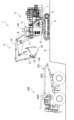
- FIG. 1 is a side view of a hydraulic excavator according to a first embodiment.
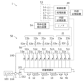
- FIG. 2 is a schematic configuration diagram of a hydraulic drive system of a hydraulic excavator.
- FIG. 3 is a functional block diagram of the control device according to the first embodiment.
- FIG. 4 is a diagram showing the excavator reference coordinate system viewed from the Y-axis direction.
- FIG. 5 is a diagram showing the shovel reference coordinate system viewed from the Z-axis direction.
- FIG. 6 is a diagram showing a correlation map Ma used by the control device according to the first embodiment during the loading operation.
- FIG. 7 is a side view of the hydraulic excavator and the loaded machine, and shows the lower limit height for passage Zamta1.
- FIG. 1 is a side view of a hydraulic excavator according to a first embodiment.
- FIG. 2 is a schematic configuration diagram of a hydraulic drive system of a hydraulic excavator.
- FIG. 3 is a functional block diagram of the
- FIG. 8 is a plan view of the hydraulic excavator and the loaded machine, and shows the control start turning angle ⁇ swsa1 and the interference prevention angle ⁇ swta1.
- FIG. 9 is a plan view of the hydraulic excavator and the loaded machine, and shows the loading platform arrival angle ⁇ swta2.
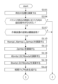
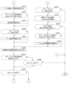
- FIG. 10 is a flowchart showing an example of the flow of the loading operation support control process executed by the control device according to the first embodiment, and shows the processes of steps S101 to S122.
- FIG. 11 is a flowchart showing an example of the flow of the loading operation support control process executed by the control device according to the first embodiment, and shows the processes of steps S125 to S166.
- FIG. 12 is a diagram illustrating the main operations of the hydraulic excavator 1.
- FIG. 12 is a diagram illustrating the main operations of the hydraulic excavator 1.
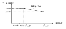
- FIG. 13 is a diagram showing a correlation map Mb used by the control device according to the second embodiment during the preparation operation.
- FIG. 14 is a flowchart showing an example of the process flow of the preparation operation support control executed by the control device according to the second embodiment, and shows the processes of steps S201 to S222.
- FIG. 15 is a flowchart illustrating an example of the process flow of the preparation operation support control executed by the control device according to the second embodiment, and illustrates the processes of steps S231 to S269.
- FIG. 16 is a plan view of the hydraulic excavator and the loaded machine, and shows the loading platform internal limit angle ⁇ swta3.
- FIG. 17 is a side view of the hydraulic excavator and the loaded machine, and shows the lower limit height within the vessel Zamta2.
- FIG. 16 is a plan view of the hydraulic excavator and the loaded machine, and shows the loading platform internal limit angle ⁇ swta3.
- FIG. 17 is a side view of the hydraulic excavator and
- FIG. 18 is a diagram showing a correlation map Ma' used by the control device according to the third embodiment during the loading operation.
- FIG. 19A is a diagram illustrating an example of the arrangement of support control execution switches.
- FIG. 19B is a diagram illustrating another example of the arrangement of the support control execution switch.
- FIG. 20 is a flowchart showing the flow of processing of loading operation support control executed by the control device according to modification 1-1.
- FIG. 21 is a functional block diagram of a control device according to modification 1-2.
- FIG. 22 is a flowchart showing the process flow of loading operation support control executed by the control device according to Modification 1-2.
- FIG. 23 is a flowchart showing an example of the flow of the loading operation support control process executed by the control device according to the third modification, and shows the processes of steps S125 to S166.
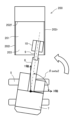
- FIG. 24 is a side view of a hydraulic excavator according to modification example 4.
- traveling hydraulic motor 4 when there are multiple identical components, a lowercase letter of the alphabet may be added to the end of the code, but the lowercase letter of the alphabet may be omitted and the multiple components may be written together. .
- traveling hydraulic motor 4a and 4b when two identical traveling hydraulic motors 4a and 4b are present, they may be collectively referred to as traveling hydraulic motor 4.
- loading operation support control the control executed by the control device to support the loading operation according to the operator's operation
- preparation operation support control the control executed by the control device to support the preparation operation according to the operator's operation
- FIG. 1 is a side view of a hydraulic excavator 1 according to a first embodiment of the present invention.
- the hydraulic excavator 1 according to the present embodiment is a backhoe excavator in which a bucket 10 is attached to the tip of an arm 9 facing backward.
- the hydraulic excavator 1 performs excavation work to excavate a surface to be excavated such as the ground, and loading work to load excavated materials such as excavated earth and sand onto the platform 201 of a loading machine 200 such as a transport vehicle such as a dump truck. and do it.
- the hydraulic excavator 1 performs a transport operation in which the upper rotating body 7 is rotated to transport the excavated material in the bucket 10 to above the loaded machine 200, and a transport operation in which the bucket 10 is moved in the dumping direction to transport the excavated material in the bucket 10.
- a discharging operation is performed to discharge the loaded machine 200 onto the loading platform 201 of the loaded machine 200.
- the loading platform 201 includes a pair of left and right side parts 202l, 202r (see FIG. 8), a front side part 202f, and a bottom part 203 (see FIG. 8) to which these plurality of side parts 202l, 202r, 202f are connected. It is a vessel (tray) with an open top surface. The left side 202l and the right side 202r are arranged to face each other.
- the hydraulic excavator 1 includes a vehicle body (machine main body) 3 and an articulated working device 2 attached to the vehicle body 3.
- the vehicle body 3 includes a lower traveling body 5 and an upper rotating body 7 that is rotatably provided with respect to the lower traveling body 5.
- the lower traveling body 5 is driven by a right crawler drive hydraulic motor 4a (see FIG. 2) that drives the right crawler, and a left crawler drive hydraulic motor 4b (see FIG. 2) that drives the left crawler. do.
- the upper rotating body 7 is attached to the upper part of the lower traveling body 5 via a swing device, and is rotated by a swing hydraulic motor 6 of the swing device.
- the traveling hydraulic motor 4a for driving the right crawler and the traveling hydraulic motor 4b for driving the left crawler are collectively referred to as traveling hydraulic motor 4.
- the working device 2 includes a plurality of drive target members (8, 9, 10) that are rotatably connected and a plurality of hydraulic cylinders (11, 12, 13) that drive the drive target members.
- a boom 8, an arm 9, and a bucket 10, which are three driven members driven by a plurality of hydraulic cylinders (11, 12, 13), are connected in series.
- the base end of the boom 8 is rotatably connected to the front part of the upper revolving structure 7 by a boom pin 8a (see FIG. 4).
- the base end of the arm 9 is rotatably connected to the distal end of the boom 8 by an arm pin 9a.
- the bucket 10 is rotatably connected to the tip of the arm 9 by a bucket pin 10a.
- the boom pin 8a, the arm pin 9a, and the bucket pin 10a are arranged parallel to each other, and each of the driven members (8, 9, 10) is relatively rotatable within the same plane.
- the boom 8 is rotated in the vertical direction by the expansion and contraction movement of the boom cylinder 11.
- the arm 9 rotates in the front-rear direction (dump direction and cloud direction) by the expansion and contraction movement of the arm cylinder 12.
- the bucket 10 rotates in the front-rear direction (dump direction and cloud direction) by the expansion and contraction movement of the bucket cylinder 13.
- the boom cylinder 11 has one end connected to the boom 8 and the other end connected to the frame of the upper revolving structure 7.
- the arm cylinder 12 has one end connected to the arm 9 and the other end connected to the boom 8.
- the bucket cylinder 13 has one end connected to the bucket 10 via a bucket link 16 and the other end connected to the arm 9.
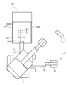
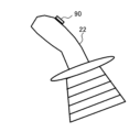
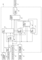
- FIG. 2 is a schematic configuration diagram of the hydraulic drive system 50 of the hydraulic excavator 1.
- the hydraulic drive system 50 includes an engine 103 that is a prime mover mounted on the upper revolving structure 7, and a main pump 102 and a pilot pump 104 that are hydraulic pumps driven by the engine 103.
- Main pump 102 and pilot pump 104 are driven by engine 103 and discharge hydraulic oil.
- the hydraulic drive system 50 includes a flow control valve 101 that controls the flow rate and flow direction of hydraulic oil discharged from the main pump 102, and a plurality of electromagnetic proportional valves 51 that outputs operating pressure as an operation signal to the flow control valve 101. , a control device 40 that outputs a control signal to the electromagnetic proportional valve 51, and operating devices 20 and 21 that are operated by an operator and output signals corresponding to the amount of operation and the direction of operation to the control device 40.
- the operating devices 20 and 21 are installed in a driver's cab 71 (see FIG. 1) provided in the upper revolving structure 7.
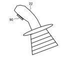
- the operation device 20 for operation includes a right operation lever 22a for operating the boom 8 and the bucket 10, and a left operation operation lever 22b for operating the arm 9 and the upper revolving structure 7. That is, the operating device 20 has functions as a boom operating device, a bucket operating device, an arm operating device, and a swing operating device.
- the operating device 21 for traveling includes a right traveling operation lever 23a for operating the right crawler and a left traveling operation lever 23b for operating the left crawler.
- the work operation right lever 22a and the work operation left lever 22b are collectively referred to as the operation lever 22, and the travel operation right lever 23a and the travel operation left lever 23b are collectively referred to as the operation lever 23.
- an electrical signal representing the amount of operation and an operating direction is input from the operating device 20 to the control device 40, a control signal is output from the control device 40 to the electromagnetic proportional valve 51, and the electromagnetic proportional valve 51 outputs a control signal.
- This is an electric lever type operating system in which operating pressure is output to the flow control valve 101.
- the hydraulic excavator 1 includes an operation detection device 56 that detects the amount and direction of operation of the operation levers 22 and 23 and outputs a signal representing the detection result to the control device 40.
- the operation detection device 56 includes an operation amount sensor 52a that detects the arm cloud operation amount and arm dump operation amount by the work operation left lever 22b, and an operation amount sensor 52a that detects the right turning operation amount and the left turning operation amount by the work operation left lever 22b.
- the amount sensor 52b, the operation amount sensor 52c that detects the boom raising operation amount and boom lowering operation amount by the work operation right lever 22a, and the operation amount sensor 52c that detects the bucket cloud operation amount and bucket dump operation amount by the work operation right lever 22a.
- the plurality of operation amount sensors 52 are, for example, rotary encoders or potentiometers that can detect the operation amount and operation direction of the operation levers 22 and 23.
- the control device 40 controls the rotation operation of the working device 2, the traveling operation of the lower traveling body 5, and the upper Controls the turning operation of the rotating structure 7.
- the control device 40 outputs a control signal according to the amount and direction of operation of the operating levers 22 and 23 by the operator to the electromagnetic proportional valves 51 (51a to 51l).
- the electromagnetic proportional valve 51 is provided in a pilot line 100 to which pressure oil is supplied from a pilot pump 104.
- the electromagnetic proportional valve 51 operates when a control signal from the control device 40 is input, and outputs the secondary pressure generated by reducing the primary pressure of the pilot line 100 to the flow rate control valve 101 as an operating pressure.
- the flow rate control valve 101 includes a plurality of spool valves provided for each of a plurality of hydraulic actuators (swivel hydraulic motor 6, arm cylinder 12, boom cylinder 11, bucket cylinder 13, traveling hydraulic motor 4a, and traveling hydraulic motor 4b). ing.
- the operating pressure output by the electromagnetic proportional valve 51 is guided to a pressure receiving chamber of the spool valve, and the spool is operated.
- the hydraulic oil discharged from the main pump 102 is supplied to the corresponding hydraulic actuator through the spool valve, and the hydraulic actuator is operated.
- the electromagnetic proportional valves 51a and 51b output operating pressure for controlling the pressure oil supplied to the swing hydraulic motor 6 to the pressure receiving chamber of the spool valve for driving the swing hydraulic motor 6 of the flow control valve 101.
- the electromagnetic proportional valves 51c and 51d output operating pressure for controlling the pressure oil supplied to the arm cylinder 12 to a pressure receiving chamber of a spool valve for driving the arm cylinder 12 of the flow control valve 101.
- the electromagnetic proportional valves 51e and 51f output operating pressure for controlling the pressure oil supplied to the boom cylinder 11 to a pressure receiving chamber of a spool valve for driving the boom cylinder 11 of the flow control valve 101.
- the electromagnetic proportional valves 51g and 51h output operating pressure for controlling the pressure oil supplied to the bucket cylinder 13 to a pressure receiving chamber of a spool valve for driving the bucket cylinder 13 of the flow control valve 101.
- the electromagnetic proportional valves 51i and 51j output operating pressure for controlling the pressure oil supplied to the travel hydraulic motor 4a to the pressure receiving chamber of the spool valve for driving the travel hydraulic motor 4a of the flow control valve 101.
- the electromagnetic proportional valves 51k and 51l output operating pressure for controlling the pressure oil supplied to the travel hydraulic motor 4b to the pressure receiving chamber of the spool valve for driving the travel hydraulic motor 4b of the flow control valve 101.
- the boom cylinder 11, arm cylinder 12, and bucket cylinder 13 are expanded and contracted by the supplied pressure oil, respectively, and rotate the boom 8, arm 9, and bucket 10.
- the swing hydraulic motor 6 is rotated by the supplied pressure oil, and swings the upper revolving structure 7.
- the traveling hydraulic motor 4a and the traveling hydraulic motor 4b are rotated by the supplied pressure oil and cause the lower traveling body 5 to travel. Note that even if the operator does not operate the operating levers 22 and 23, the hydraulic actuator ( 4a, 4b, 6, 11, 12, 13).
- the hydraulic excavator 1 includes a posture detection device 53 that detects the postures of the working device 2 and the vehicle body 3.
- the attitude detection device 53 includes a boom angle sensor 14, an arm angle sensor 15, a bucket angle sensor 17, an inclination angle sensor 18, and a turning angle sensor 19 as a plurality of attitude sensors.
- the boom angle sensor 14 is attached to the boom pin 8a, detects the rotation angle of the boom 8 with respect to the upper rotating structure 7, and outputs a signal representing the detection result to the control device 40.
- Arm angle sensor 15 is attached to arm pin 9a, detects the rotation angle of arm 9 with respect to boom 8, and outputs a signal representing the detection result to control device 40.
- Bucket angle sensor 17 is attached to bucket link 16, detects the rotation angle of bucket 10 with respect to arm 9, and outputs a signal representing the detection result to control device 40.
- the control device 40 obtains each rotation angle of the boom 8, arm 9, and bucket 10 using each angle sensor 14, 15, and 17.
- each rotation angle of the boom 8, arm 9, and bucket 10 is not limited to this.
- the control device 40 detects each angle of the boom 8, arm 9, and bucket 10 with respect to a reference plane such as a horizontal surface using an inertial measurement unit (IMU), and adjusts each rotation angle of the boom 8, arm 9, and bucket 10. Each rotation angle may be obtained by conversion.
- the control device 40 detects each stroke of the boom cylinder 11, arm cylinder 12, and bucket cylinder 13 with a stroke sensor, and converts each stroke into each rotation angle of the boom 8, arm 9, and bucket 10, thereby converting each rotation angle into the rotation angle of the boom cylinder 11, arm cylinder 12, and bucket cylinder 13. You may obtain it.
- the inclination angle sensor 18 is attached to the upper rotating body 7, detects the inclination angle of the upper rotating body 7 (vehicle body 3) with respect to a reference plane such as a horizontal plane, and outputs a signal representing the detection result to the control device 40.
- the turning angle sensor 19 is attached to the turning device between the lower traveling body 5 and the upper rotating body 7, detects the turning angle of the upper rotating body 7 with respect to the lower traveling body 5, and sends a signal representing the detection result to the control device 40. Output to.
- each rotation angle of the boom 8, arm 9, and bucket 10 is a parameter representing the attitude of the working device 2. That is, the boom angle sensor 14, the arm angle sensor 15, and the bucket angle sensor 17 function as attitude sensors that detect the attitude of the working device 2. Further, the inclination angle of the upper rotating body 7 and the turning angle of the upper rotating body 7 with respect to the lower traveling body 5 are parameters representing the attitude of the upper rotating body 7 (vehicle body 3). That is, the inclination angle sensor 18 and the turning angle sensor 19 function as attitude sensors that detect the attitude of the upper rotating structure 7 (vehicle body 3).
- the hydraulic excavator 1 is equipped with an object position detection device 54 that detects the types and positions of objects existing around the hydraulic excavator 1.
- the object position detection device 54 is, for example, a LiDAR (Light Detection And Ranging) or a stereo camera, and is attached to the upper part of the driver's cab 71 or the like.
- the object position detection device 54 detects the loading platform (vessel) 201 of the loaded machine 200 into which the excavated material excavated by the working device 2 is loaded, and also detects the load with respect to the object position detection device 54 provided on the upper revolving structure 7. The relative position of the loading platform 201 of the loading machine 200 is detected.
- a plurality of object position detection devices 54 may be attached to the hydraulic excavator 1.
- the control device 40 includes processing devices such as a CPU (Central Processing Unit), an MPU (Micro Processing Unit), and a DSP (Digital Signal Processor), an internal storage device such as a RAM (Random Access Memory), and a ROM (Read Only Memory); These are computers with external I/Fs (Interfaces) etc. connected to each other via a bus.
- An external I/F of the control device 40 is connected to an operation detection device 56, a posture detection device 53, an object position detection device 54, and an external storage device (not shown) such as a hard disk drive or a large-capacity flash memory.
- the ROM stores programs that can execute various operations. That is, the ROM is a storage medium that can read a program that implements the functions of this embodiment.
- a processing device is an arithmetic device that expands a program stored in a ROM into a RAM and executes arithmetic operations. performs predetermined arithmetic processing.
- the input section of the external I/F converts signals input from various devices (operation detection device 56, posture detection device 53, object position detection device 54, etc.) so that they can be calculated by the processing device. Further, the output section of the external I/F generates an output signal according to the calculation result in the processing device, and outputs the signal to various devices (such as the electromagnetic proportional valve 51).
- the attitude detection device 53 includes an attitude sensor (14, 15, 17) that detects the attitude of the working device 2 described above, and an attitude sensor (18, 19) that detects the attitude of the upper rotating body 7 (vehicle body 3). It consists of:
- FIG. 3 is a functional block diagram of the control device 40.
- the control device 40 executes a program stored in the ROM, thereby controlling the posture calculation section 41, loaded machine position calculation section 42, speed calculation section 43, speed vector calculation section 44, It functions as a condition determination section 45 , a target angle calculation section 46 , a posture comparison section 47 , a target speed calculation section 48 , a correlation map generation section 49 , and an actuator control section 39 .
- the ROM of the control device 40 stores in advance an excavator reference coordinate system used to specify the positions and postures of the components of the hydraulic excavator 1.
- the excavator reference coordinate system of this embodiment is defined as a right-handed coordinate system in which the origin O is the point where the rotation center axis and the ground G intersect.
- the forward direction of the undercarriage 5 is defined as the positive direction of the X-axis.
- the direction extending upward from the origin O in parallel with the rotation center axis is defined as the positive direction of the Z axis.
- the excavator reference coordinate system of this embodiment is orthogonal to each of the X-axis and the Z-axis, and the left side of the undercarriage 5 is defined as the positive direction of the Y-axis.
- the shovel reference coordinate system of the present embodiment is a coordinate system set with the undercarriage body 5 as a reference, and the XY plane is fixed to the ground (running surface) G with which the undercarriage body 5 is in contact.
- the turning angle ⁇ sw of the upper rotating body 7 is 0 degrees when the hydraulic excavator 1 is in the reference posture, that is, when the working device 2 is in a state parallel to the X-axis.
- the rotation angle ⁇ sw of the upper revolving structure 7 is 0 degrees
- the operating plane of the working device 2 is parallel to the XZ plane
- the direction of the raising operation of the boom 8 is the positive direction of the Z axis
- the dump direction is the positive direction of the X axis.
- the attitude calculation unit 41 calculates the attitude of the components of the hydraulic excavator 1 in the excavator reference coordinate system from the detection signal of the attitude detection device 53. Specifically, the posture calculation unit 41 calculates the rotation angle (hereinafter also referred to as boom angle) ⁇ bm of the boom 8 with respect to the X axis from the detection signal of the rotation angle of the boom 8 output from the boom angle sensor 14. do. The attitude calculation unit 41 calculates the rotation angle (hereinafter also referred to as arm angle) ⁇ am of the arm 9 with respect to the boom 8 from the detection signal of the rotation angle of the arm 9 output from the arm angle sensor 15.
- the rotation angle hereinafter also referred to as boom angle
- the attitude calculation unit 41 calculates the rotation angle (hereinafter also referred to as bucket angle) ⁇ bk of the bucket 10 with respect to the arm 9 from the detection signal of the rotation angle of the bucket 10 output from the bucket angle sensor 17.
- the attitude calculation unit 41 calculates the turning angle ⁇ sw of the upper rotating structure 7 with respect to the X axis (the lower traveling structure 5) from the detection signal of the turning angle of the upper rotating structure 7 output from the turning angle sensor 19.
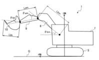
- the posture calculation unit 41 calculates the rotation angle ⁇ bm, ⁇ am, ⁇ bk of the working device 2 and the rotation angle ⁇ sw of the upper rotating body 7 based on the boom length Lbm, arm length Lam, and bucket length Lbk. , the positions of the boom 8, arm 9, and bucket 10 in the shovel reference coordinate system, that is, the plane positions specified by the X and Y coordinates and the heights from the ground G specified by the Z coordinate.
- the boom length Lbm is the length from the boom pin 8a to the arm pin 9a.
- Arm length Lam is the length from arm pin 9a to bucket pin 10a.
- the bucket length Lbk is the length from the bucket pin 10a to the tip (toe) of the bucket 10.
- the boom pin 8a is provided at a position offset by Lox in the X-axis direction from the rotation center axis (Z-axis) when the rotation angle is 0 degrees.
- the attitude calculation unit 41 calculates the inclination angle (pitch angle and roll angle) of the vehicle body 3 (lower traveling body 5) with respect to the reference plane from the detection signal of the inclination angle of the vehicle body 3 output from the inclination angle sensor 18. ) is calculated.
- the reference plane is, for example, a horizontal plane perpendicular to the direction of gravity.
- the posture calculation unit 41 calculates the ground angle ⁇ , which is the angle of the bucket 10 with respect to the ground G, from the rotation angles ⁇ bm, ⁇ am, and ⁇ bk of the working device 2.
- the ground angle ⁇ of the bucket 10 is the angle that a straight line passing through the tip of the bucket 10 and the bucket pin 10a makes with the ground G.
- the loaded machine position calculation section 42 shown in FIG. Based on the rotation angle ⁇ sw of the upper revolving body 7 calculated by The plane position specified by the coordinates and the Y coordinate, and the height from the ground G specified by the Z coordinate) are calculated. In this way, the control device 40 according to the present embodiment uses the object position detection device 54 to obtain the relative position of the loading platform 201 with respect to the hydraulic excavator 1 (X, Y, Z coordinates in the excavator reference coordinate system).
- the positional information of the loading platform 201 acquired by the control device 40 includes, for example, the position coordinates of the four corners of the upper surface of the loading platform 201, that is, the front and rear ends of the upper edge of the left side 202l of the loading platform 201, and the right side 202r. These include the position coordinates of the front end and rear end of the upper edge of .
- the speed calculation unit 43 calculates the operation command speed of each hydraulic actuator 6, 11, 12, 13 based on the detection signal from the operation detection device 56.
- the ROM of the control device 40 stores in advance a speed table showing the correspondence between the operation amounts of the operation levers 22 and 23 and the operation command speeds of the hydraulic actuators 6, 11, 12, and 13. .
- the speed calculation unit 43 refers to this speed table and determines the operation command speed of each hydraulic actuator 6, 11, 12, 13 from the operation amount included in the operation information of the operation levers 22, 23 output from the operation detection device 56. Calculate.
- the speed calculation unit 43 converts the operation command speed of the swing hydraulic motor 6 into the swing speed ⁇ sw of the upper swing structure 7.
- the speed calculation unit 43 converts the operation command speed of the boom cylinder 11 into the rotation speed of the boom 8.
- the speed calculation unit 43 converts the operation command speed of the arm cylinder 12 into the rotation speed of the arm 9.
- the speed calculation unit 43 converts the operation command speed of the bucket cylinder 13 into the rotation speed of the bucket 10.
- the speed calculation unit 43 calculates the actual rotational speed of the working device 2 from the temporal changes in the rotational angles ⁇ bm, ⁇ am, and ⁇ bk of the working device 2 calculated by the posture calculation unit 41.
- the speed calculating unit 43 calculates the actual turning speed ⁇ swr of the upper rotating body 7 from the time change of the turning angle ⁇ sw of the upper rotating structure 7 calculated by the attitude calculating unit 41.
- the speed vector calculation section 44 calculates a speed vector generated in the work device 2 based on the calculation results of the posture calculation section 41 and the speed calculation section 43. Specifically, the speed vector calculation unit 44 calculates the rotation angles ⁇ bm, ⁇ am, ⁇ bk of the working device 2 calculated by the posture calculation unit 41 and the rotation angle ⁇ sw of the upper rotating body 7, and the rotation angle ⁇ sw of the upper rotating body 7 calculated by the speed calculation unit 43. The speed vector of the tip of the arm 9 is calculated based on the rotation speed of the working device 2 and the rotation speed of the upper rotating body 7.
- the condition determination unit 45 determines whether a loading operation support control execution condition (first interference prevention control execution condition), which is a condition for executing loading operation support control as interference prevention control to be described later, is satisfied. .
- the loading operation support control execution conditions include the following (condition 1) and (condition 2).
- the loading operation support control execution condition is established when both (condition 1) and (condition 2) are satisfied, and is not established when either (condition 1) or (condition 2) is not satisfied.
- (Condition 1) The bucket 10 is rotated in a direction approaching the side portion 202 of the loading platform 201 from the outside of the loading platform 201 in plan view.
- Condition 2 The posture of the working device 2 is the transport posture. If both (Condition 1) and (Condition 2) are satisfied, it can be determined that the operator has an intention to carry out a transport operation to transport the excavated material.
- the condition determining unit 45 determines, based on the relative position of the loading platform 201 with respect to the hydraulic excavator 1 and the moving direction of the working device 2, the operator determines whether the bucket 10 approaches the side 202 of the loading platform 201 from the outside of the loading platform 201 in plan view. Determine whether or not a turning operation has been performed. For example, the condition determination unit 45 determines the position (plane position and height) of the loading platform 201 of the loaded machine 200 calculated by the loaded machine position calculation unit 42 and the arm 9 calculated by the speed vector calculation unit 44. Based on the velocity vector of the tip (parameter indicating the moving direction of the bucket 10), the operator performs a turning operation in a direction in which the bucket 10 approaches the side of the loading platform 201 from the outside of the loading platform 201 in plan view. Determine whether
- the condition determination unit 45 determines the position of the loading platform 201 calculated by the loaded machine position calculation unit 42, the position of the tip of the arm 9 calculated by the attitude calculation unit 41, and the position detected by the operation detection device 56. Based on the operation direction of the turning operation (left turning direction or right turning direction), it is determined whether the turning operation has been performed in a direction in which the bucket 10 approaches the side part 202 of the loading platform 201 from the outside of the loading platform 201 in plan view. You may judge.
- condition determination unit 45 determines that (condition 1 ) is determined to have been established and the distance between the position of the loading platform 201 of the loaded machine 200 and the position of the hydraulic excavator 1 is a predetermined value or more, or if the turning operation is not performed, It may be determined that (condition 1) is not satisfied.
- the condition determination section 45 determines whether the posture of the working device 2 is the transport posture based on the calculation result of the posture calculation section 41. For example, the condition determination unit 45 compares the absolute value of the ground angle ⁇ of the bucket 10 calculated by the posture calculation unit 41 with the ground angle threshold value ⁇ t.
- the ground angle threshold value ⁇ t is a threshold value for determining whether the attitude of the working device 2 is the transport attitude, and is stored in advance in the ROM of the control device 40. For example, a value of about 10 degrees to 20 degrees is adopted as the ground angle threshold value ⁇ t.
- the condition determination unit 45 determines that the posture of the working device 2 is the transport posture. If the absolute value of the ground angle ⁇ of the bucket 10 calculated by the posture calculation unit 41 is larger than the ground angle threshold ⁇ t, the condition determination unit 45 determines that the posture of the working device 2 is not the transport posture.
- the loading operation support control execution condition (first interference prevention control execution condition)
- the loading operation support control that is interference prevention control during the loading operation is executed.
- Ru Interference prevention control is control for preventing the bucket 10 from interfering with the loading platform 201.
- loading operation support control which is interference prevention control for preventing the bucket 10 from interfering with the loading platform 201, is executed.
- the control device 40 controls whether the bucket 10 is connected to the loaded machine.
- a correlation map Ma (see FIG. 6) for supporting the operator's operation is generated and stored in the storage device so that the loading platform 200 can be moved to the discharge position without interfering with the loading platform 201.
- FIG. 6 is a diagram showing a correlation map Ma used by the control device 40 during the loading operation.
- the correlation map Ma is a map that defines the lower limit value of the arm tip height according to the turning angle.
- the arm tip height is the height (distance in the Z-axis direction) from the ground G to the tip of the arm 9 (for example, the center of the bucket pin 10a).
- the vertical axis indicates the lower limit of the arm tip height.
- Zamta 1 has a height of the tip of the arm 9 (interference prevention height), hereinafter also referred to as the lower limit height for passage.
- the lower limit height for passage Zamta1 is the height in the shovel reference coordinate system that the tip of the arm 9 should reach in order to cause the bucket 10 to pass above the side 202 of the loading platform 201. Therefore, if the arm tip height is greater than the lower limit height for passage Zamta1, the swinging operation of the upper revolving body 7 allows the bucket 10 to be moved from the outside to the inside of the loading platform 201 without interfering with the loading platform 201.
- the horizontal axis of the correlation map Ma indicates the turning angle, and assuming that the turning angle when the hydraulic excavator 1 is in the reference posture is 0 degrees, the turning angle increases when turning to the left.
- ⁇ swsa1 is the turning angle at the position where the transport operation in the loading operation starts (operation start position), that is, the position where the loading operation support control starts (control start position), Hereinafter, it will also be referred to as the control start turning angle.
- ⁇ swta is the position where the predicted movement trajectory L of the tip of the arm 9 intersects the outer surface of the side part 202r of the loading platform 201 of the loaded machine 200 in plan view, that is, the position where the bucket 10 is on the side of the loading platform 201 in plan view.
- This is a turning angle at a position overlapping with the portion 202r (wrap position), and hereinafter also referred to as a wrap turning angle.
- the predicted movement trajectory L is a movement trajectory of the tip of the arm 9 when the arm tip height is the lower limit height for passage Zamta1.
- ⁇ swta1 is the turning angle when the working device 2 is located at the interference prevention position, and hereinafter also referred to as the interference prevention angle.
- the interference prevention position is a position near the loading platform 201 where the bucket 10 does not interfere with the loading platform 201 even if the arm tip height is lower than the interference prevention height.
- the interference prevention angle ⁇ swta1 can also be said to be a turning angle for specifying the interference prevention position.
- ⁇ swta2 is the turning angle when the bucket 10 crosses the side 202r from the outside of the loading platform 201 and the entire bucket 10 is located inside the loading platform 201, as shown in FIG. Also written as angle.
- the control device 40 refers to the correlation map Ma shown in FIG. 6 and controls the operation of the working device 2 and the upper revolving body 7 so that the arm tip height does not fall below the lower limit defined by the correlation map Ma.
- the details of the method of generating the correlation map Ma and the method of controlling the work device 2 will be described below.
- the operation start position which is the position in the circumferential direction, is specified.
- the posture calculation unit 41 calculates the turning angle ⁇ sw of the upper rotating structure 7 at the time of starting the loading operation support control (when the conditions for executing the loading operation support control are satisfied) as the control start turning angle ⁇ swsa1.
- the posture calculation unit 41 calculates the height of the tip of the arm 9 at the time of starting the loading operation support control as a control start height Zamsa1.
- the target angle calculation unit 46 calculates the height Zv, which is the position of the loading platform 201 in the Z-axis direction in the shovel reference coordinate system, calculated by the loaded machine position calculation unit 42, and By adding the predetermined set value Za, the lower limit height for passage Zamta1 is calculated.
- the height Zv of the loading platform 201 is the height from the ground G to the upper edge of the side portion 202 of the loading platform 201 in the shovel reference coordinate system.
- the set value Za is set by adding the bucket length Lbk and the margin.
- the attitude calculation unit 41 calculates the arm angle ⁇ am at the start of the loading operation support control as the control start arm angle ⁇ amsa1.
- the target angle calculation unit 46 determines the boom angle at which the arm tip height becomes the lower limit height for passing Zamta1 based on the control start arm angle ⁇ amsa1 and the lower limit height for passing Zamta1.
- a lower limit boom angle ⁇ bmta1 for passage is calculated.
- the target angle calculation unit 46 calculates the operation start position specified on the outside of the loading platform 201 based on the passing lower limit boom angle ⁇ bmta1, Among the plurality of side parts 202 of the loading platform 201, the working device 2 is located between the loading platform 201 and the side 202 that can be reached first by the working device 2 after the operation of the upper revolving body 7 (in the example shown in FIG. 8, the right side 202r).
- An interference prevention angle ⁇ swta1 that specifies an interference prevention position, which is an angular position in the rotation direction of the tip of the arm 9 that does not interfere with the device 2, is calculated.
- the arm tip height Zam which is the height of the tip of the arm 9 from the ground G in the shovel reference coordinate system, is determined by the following equation (1).
- Loz is the height of the boom pin 8a from the ground G in the shovel reference coordinate system.
- Lbm is the boom length
- Lam is the arm length
- ⁇ bm is the boom angle
- ⁇ am is the arm angle. Note that, as will be described later, the arm angle ⁇ am is maintained at the control start arm angle ⁇ amsa1 from when the loading operation support control is started until a condition for enabling the operation of the arm 9 is satisfied.
- the lower limit boom angle for passing ⁇ bmta1 which is the boom angle when the tip of the arm 9 is at the lower limit height for passing Zamta1, is determined by the following equation (2).
- Ata1, bta1, and ⁇ ta1 are coefficients related to the composition of trigonometric functions.
- the distance Rta1 from the rotation center axis (Z-axis) to the tip of the arm 9 (hereinafter also referred to as arm tip distance) when viewed from above is determined by the following equation (3). Desired.
- Lox is the distance (offset) from the rotation center axis (Z-axis) to the boom pin 8a.
- the wrap turning angle ⁇ swta is a turning angle in a state where the bucket 10 is located directly above the side portion 202 and the side portion 202 and the bucket 10 overlap in plan view.
- the predetermined margin ⁇ swtam is a margin that is added so that the working device 2 is disposed at a position outward of the loading platform 201 and away from the side portion 202.
- the margin ⁇ swtam is a negative value.
- the absolute value of the margin is at least a value greater than half the width of the bucket 10.
- the predetermined margin ⁇ swtam2 here is a margin that is added so that the working device 2 is disposed at a position toward the inside of the loading platform 201 and away from the side portion 202.
- the margin ⁇ swtam2 is a positive value.
- the absolute value of the margin is at least a value greater than half the width of the bucket 10.
- the correlation map generation unit 49 shown in FIG. 3 generates a correlation map Ma during loading operation support as shown in FIG. 6 based on the calculation result of the target angle calculation unit 46.
- the correlation map Ma from the control start rotation angle ⁇ swsa1 to the interference prevention angle ⁇ swta1, as the rotation angle increases, the lower limit value of the arm tip height increases monotonically from the control start height Zamsa1 until the interference prevention angle ⁇ swta1.
- the lower limit of the arm tip height is generated to be the lower limit height for passage Zamta1.
- the correlation map Ma is generated such that the lower limit value of the arm tip height becomes the lower limit height for passage Zamta1 when the turning angle is from the interference prevention angle ⁇ swta1 to the platform arrival angle ⁇ swta2.
- control device 40 controls the operating range of the upper rotating structure 7 from the operation start position specified by the control start rotation angle ⁇ swsa1 to the interference prevention position specified by the interference prevention angle ⁇ swta1, so that the closer to the interference prevention position the
- the lower limit value in the height direction of the working device 2 is calculated according to the angular position in the turning direction of the tip of the arm 9, which is large and becomes the lower limit height for passage (interference prevention height) Zamta1 at the interference prevention position.
- the arm angle ⁇ am may change depending on the operator's operation.
- the reach (arm tip distance) of the working device 2 when viewed from above changes, so the reach angle ⁇ swta2 in the loading platform, which is the turning angle at the position where the entire bucket fits inside the loading platform 201, is dynamic. Changes to That is, when the arm angle ⁇ am changes, the target angle calculation unit 46 recalculates the cargo platform arrival angle ⁇ swta2.
- the correlation map generation unit 49 updates the correlation map Ma based on the recalculated in-bed arrival angle ⁇ swta2.
- the attitude comparison unit 47 shown in FIG. 3 compares the turning angle ⁇ sw calculated by the attitude calculation unit 41 and the interference prevention angle ⁇ swta1 calculated by the target angle calculation unit 46, and based on the comparison result, Determine whether the activation condition for the operation is satisfied.
- the conditions for enabling the operation of the arm 9 include that the tip of the arm 9 reaches a height exceeding the interference prevention height and reaches an angular position in the turning direction that exceeds the interference prevention position.
- the posture comparison unit 47 determines that the tip of the arm 9 does not exceed the interference prevention position. In other words, the posture comparison unit 47 determines that the validation condition is not satisfied.
- the attitude comparison unit 47 determines that the tip of the arm 9 is beyond the interference prevention position.
- the lower limit in the height direction of the working device 2 at the interference prevention position is the lower limit height for passage (interference prevention height) Zamta1. Therefore, the posture comparison unit 47 determines that the enabling condition is satisfied when the turning angle ⁇ sw is equal to or greater than the interference prevention angle ⁇ swta1.
- the posture comparison section 47 compares the arm tip height Zam calculated by the posture calculation section 41 and the lower limit height for passage Zamta1 calculated by the target angle calculation section 46.
- the posture comparison unit 47 establishes conditions for executing control to automatically perform boom raising operation (hereinafter also referred to as automatic boom raising control execution conditions) based on the comparison result between the arm tip height Zam and the lower limit height for passing Zamta1. Determine whether or not.
- the automatic boom raising control execution conditions include at least the following (condition 3).
- the automatic boom raising control execution condition is satisfied when the following (condition 3) is satisfied while the interference prevention control is being executed, and is not satisfied when (condition 3) is not satisfied.
- Condition 3 The arm tip height Zam is less than or equal to the lower limit height for passage Zamta1.
- the attitude comparison unit 47 compares the turning angle ⁇ sw calculated by the attitude calculation unit 41 and the arrival angle ⁇ swta2 in the loading platform calculated by the target angle calculation unit 46, so that the bucket 10 turns beyond the interference prevention position. After that, whether or not the bucket 10 has passed through the side 202 of the loading platform 201 (among the sides 202r and 202l, only the side 202r that can be reached first) in a plan view, that is, whether the entire bucket 10 has passed the side 202r in a plan view. It is determined whether the vehicle has crossed over and reached the inside of the loading platform 201, which is a position in the turning direction in front of the side portion 202l.
- the posture comparison unit 47 determines that the entire bucket 10 has not reached the inside of the loading platform 201 when the turning angle ⁇ sw is less than the loading platform arrival angle ⁇ swta2. The posture comparison unit 47 determines that the entire bucket 10 has reached the inside of the loading platform 201 when the turning angle ⁇ sw becomes equal to or greater than the loading platform arrival angle ⁇ swta2.
- the target speed calculation section 48 calculates the target speed of the hydraulic actuator that drives the boom 8, arm 9, bucket 10, upper revolving structure 7, etc. based on the operation command speed calculated by the speed calculation section 43.
- the actuator control unit 39 controls the electromagnetic proportional valve 51 so that each hydraulic actuator (boom cylinder 11, arm cylinder 12, bucket cylinder 13, swing hydraulic motor 6, etc.) operates at the target speed calculated by the target speed calculation unit 48. Outputs a control signal to.
- the target speed calculation unit 48 calculates the target speed of each hydraulic actuator based on the attitude of the hydraulic excavator 1 and the correlation map Ma calculated by the attitude calculation unit 41.
- the details of how the target speed calculation unit 48 calculates the target speed of each hydraulic actuator in the loading operation support control are as follows.
- the target speed calculation section 48 controls the operation of the arm 9 by the posture comparison section 47 until the turning angle ⁇ sw calculated by the posture calculation section 41 reaches the interference prevention angle ⁇ swta1. While it is determined that the enabling condition is not satisfied, a disabling process is executed to disable the arm operation by the operator. In the invalidation process, the target speed calculation unit 48 sets the target speed of the arm cylinder 12 to 0 (zero) even if the operation command speed of the arm cylinder 12 calculated by the speed calculation unit 43 is not 0 (zero). Set to .
- the control device 40 disables the operation of the arm 9 by the operating device 20 while the upper revolving structure 7 is in operation and until the enabling condition is satisfied. Make it. In other words, the control device 40 disables the operation of the arm 9 by the arm operating device (operating device 20) during the operation of the upper revolving structure 7 from the operation start position to the interference prevention position.
- the target speed calculation unit 48 does not perform the invalidation process when the attitude comparison unit 47 determines that the activation condition for the operation of the arm 9 is satisfied. That is, the target speed calculation unit 48 sets the operation command speed of the arm cylinder 12 calculated by the speed calculation unit 43 as the target speed of the arm cylinder 12. In this manner, the control device 40 according to the present embodiment enables the operation of the arm 9 by the operating device 20 when the enabling condition is satisfied in the loading operation support control.
- the target speed calculation unit 48 sets the boom to a predetermined target speed of the boom cylinder 11 regardless of the boom operation by the operator. Set the automatic raising speed.
- the boom automatic raising speed is stored in the ROM of the control device 40 in advance. Note that when the attitude comparison unit 47 determines that the automatic boom raising control execution condition is not satisfied, the target speed calculation unit 48 does not perform the process of setting the boom automatic raising speed as the target speed of the boom cylinder 11. do not have.
- the target speed calculation unit 48 compares the arm tip height Zam calculated by the posture calculation unit 41 with the correlation map Ma generated by the correlation map generation unit 49, and calculates the arm tip height Zam by the rotation operation from the correlation map.
- the target turning speed is set so as not to fall below the lower limit defined by Ma.
- the target speed calculation unit 48 calculates the limit swing speed ⁇ swt that satisfies the slope ⁇ of the correlation map Ma from the rotation speed (angular velocity) ⁇ bm of the boom 8 calculated by the speed calculation unit 43.
- the target speed calculating unit 48 compares the turning speed ⁇ sw calculated by the speed calculating unit 43 according to the operator's turning operation with the limit turning speed ⁇ swt, and based on the comparison result, the arm tip is adjusted according to the operator's turning operation. It is determined whether the height Zam is less than the lower limit defined by the correlation map Ma.
- the target speed calculation unit 48 determines that the arm tip height Zam does not fall below the lower limit defined by the correlation map Ma due to the operator's turning operation. If the turning speed ⁇ sw is greater than the limit turning speed ⁇ swt, the target speed calculation unit 48 determines that the arm tip height Zam falls below the lower limit defined by the correlation map Ma due to the operator's turning operation.
- the target speed calculation unit 48 calculates the rotation hydraulic motor 6 calculated by the speed calculation unit 43.
- the operation command speed is set as the target speed of the swing hydraulic motor 6.
- the upper rotating body 7 operates at a turning speed ⁇ sw corresponding to the turning operation by the operator.
- the target speed calculation unit 48 sets the target speed of the swing hydraulic motor 6 to the limit swing speed ⁇ swt. Set to corresponding speed.
- the upper revolving body 7 operates at a limited rotation speed ⁇ swt that is lower than the rotation speed corresponding to the operator's rotation operation. In other words, the turning operation of the upper revolving body 7 is decelerated.
- control device 40 controls the automatic raising operation of the boom 8 and the operation of the upper rotating body 7 so that the arm tip height Zam does not fall below the lower limit defined by the correlation map Ma. Control limits.
- the target speed calculation unit 48 calculates that the arm tip height Zam is set to a lower limit value (for passing through) by the operator's arm operation. It is determined whether the height is below the lower limit height Zamta1). If the velocity vector of the arm tip computed by the velocity vector computing unit 44 does not include a downward component, the target velocity computing unit 48 calculates the arm tip height Zam based on the correlation map Ma by the operator's arm operation. It is determined that the height does not fall below the lower limit value (lower limit height for passage Zamta1) defined by .
- the target speed calculation unit 48 calculates that the arm tip height Zam is adjusted to the correlation map Ma by the operator's arm operation. It is determined that the height is below the lower limit value (lower limit height for passage Zamta1) defined by.
- the target speed calculation unit 48 calculates the speed of the boom cylinder 11. Set the target speed to 0 (zero). Further, the target speed calculation unit 48 sets the operation command speed of the arm cylinder 12 calculated by the speed calculation unit 43 as the target speed of the arm cylinder 12.
- the target speed calculation unit 48 calculates the arm tip height Zam.
- a target speed in the extension direction of the boom cylinder 11 (the raising direction of the boom 8) is calculated so that Zam does not fall below the lower limit defined by the correlation map Ma. Note that instead of calculating the target speed of the boom cylinder 11 in the extension direction, or in addition to calculating the target speed of the boom cylinder 11 in the extension direction, the target speed calculation unit 48 sets the target speed of the arm cylinder 12 to 0. (zero).
- control device 40 controls the arm that operates in response to the operation of the arm 9 by the operating device 20 when it is not determined that the bucket 10 has passed the side portion 202 of the loading platform 201 in plan view.
- the operation of at least one of the boom 8 and the arm 9 is controlled so that the height of the tip of the boom 9 does not fall below the lower limit height for passage (interference prevention height) Zamta1.
- the control device 40 ends the loading operation support control when the turning angle ⁇ sw becomes equal to or greater than the loading platform arrival angle ⁇ swta2. That is, the target speed calculation section 48 sets the operation command speed of the arm cylinder 12 calculated by the speed calculation section 43 as the target speed of the arm cylinder 12 when the turning angle ⁇ sw becomes equal to or greater than the cargo platform arrival angle ⁇ swta2.
- the control device 40 when it is determined that the bucket 10 has passed the side part 202 of the loading platform 201 in plan view, the control device 40 according to the present embodiment moves the bucket 10 to a position lower than the lower limit height for passage (interference prevention height) Zamta1. The movement of the tip of the arm 9 is permitted.
- FIGS. 10 and 11 An example of the flow of the loading operation support control process executed by the control device 40 will be described with reference to FIGS. 10 and 11.
- the processes shown in the flowcharts of FIGS. 10 and 11 are started when an ignition switch (not shown) is turned on, and are repeatedly executed at a predetermined control cycle.
- step S101 the loaded machine position calculation unit 42 calculates the relative position of the loading platform 201 of the loaded machine 200 with respect to the hydraulic excavator 1 based on the detection result of the object position detection device 54. Calculate.
- the condition determination unit 45 allows the operator to determine whether or not the bucket can be adjusted in plan view based on the position of the loading platform 201 calculated in step S101 and the speed vector of the arm tip calculated by the speed vector calculation unit 44. It is determined whether or not a turning operation has been performed in the direction in which the vehicle 10 approaches the side portion 202 of the loading platform 201 from the outside of the loading platform 201.
- step S104 If it is determined in step S104 that the operator has performed a turning operation in a direction in which the bucket 10 approaches the side portion 202 of the loading platform 201 from the outside of the loading platform 201 in plan view, the process proceeds to step S107. In step S104, if it is determined that the operator has not performed a turning operation in the direction in which the bucket 10 approaches the side portion 202 of the loading platform 201 from the outside of the loading platform 201 in plan view, as shown in the flowcharts of FIGS. 10 and 11. Processing ends.
- step S107 the condition determination unit 45 determines whether the attitude of the working device 2 is the transport attitude based on the ground angle ⁇ of the bucket 10 calculated by the attitude calculation unit 41. If it is determined in step S107 that the posture of the work device 2 is the transport posture, the process proceeds to step S110. If it is determined in step S107 that the posture of the working device 2 is not the transportation posture, the processing shown in the flowcharts of FIGS. 10 and 11 ends.
- step S110 the posture calculation unit 41 calculates a control start turning angle ⁇ swsa1, a control start arm angle ⁇ amsa1, and a control start height Zamsa1.
- the target angle calculation unit 46 calculates the lower limit height for passage Zamta1. In the next step S116, the target angle calculation unit 46 calculates the lower limit boom angle for passing ⁇ bmta1 and the wrap turning angle ⁇ swta. In the next step S119, the target angle calculation unit 46 calculates the interference prevention angle ⁇ swta1 and the platform arrival angle ⁇ swta2.
- the correlation map generation unit 49 In the next step S122, the correlation map generation unit 49 generates a correlation map Ma (see FIG. 6) based on the calculation results in steps S110, S113, and S119.
- step S125 the attitude comparison unit 47 determines whether the current turning angle ⁇ sw calculated by the attitude calculation unit 41 is less than the interference prevention angle ⁇ swta1 calculated in step S119. If it is determined in step S125 that the current turning angle ⁇ sw is less than the interference prevention angle ⁇ swta1, the process proceeds to step S128. If it is determined in step S125 that the current turning angle ⁇ sw is equal to or greater than the interference prevention angle ⁇ swta1, the enabling condition for operating the arm 9 is satisfied, and the process proceeds to step S145.
- step S1208 the attitude comparison unit 47 determines whether the current arm tip height Zam calculated by the attitude calculation unit 41 is less than or equal to the lower limit height for passage Zamta1 calculated in step S113. If it is determined in step S128 that the current arm tip height Zam is less than or equal to the lower limit height for passage Zamta1, the process proceeds to step S131. If it is determined in step S128 that the current arm tip height Zam is greater than the lower limit height for passage Zamta1, the process proceeds to step S134.
- step S131 the target speed calculation unit 48 sets the target speed of the boom cylinder 11 to a predetermined boom automatic raising speed.
- step S134 the target speed calculation unit 48 determines that the arm tip height Zam is defined by the correlation map Ma according to the operator's turning operation, based on the turning speed ⁇ sw corresponding to the operator's turning operation and the limit turning speed ⁇ swt. Determine whether the value is below the lower limit. If it is determined in step S134 that the arm tip height Zam is less than the lower limit defined by the correlation map Ma due to the operator's turning operation, the process proceeds to step S137. If it is determined in step S134 that the arm tip height Zam does not fall below the lower limit defined by the correlation map Ma due to the operator's turning operation, the process proceeds to step S140.
- step S137 the target speed calculation unit 48 sets the target speed of the swing hydraulic motor 6 to a speed corresponding to the limited swing speed ⁇ swt.
- the turning operation and the boom raising operation are performed in combination so that the arm tip height does not fall below the lower limit defined by the correlation map Ma.
- step S134 the operation command speed corresponding to the amount of swing operation by the operator is set as the target speed of the swing hydraulic motor 6.
- step S140 the target speed calculation section 48 determines whether or not there is an arm operation by the operator based on the operation command speed of the arm cylinder 12 calculated by the speed calculation section 43.
- the target speed calculation unit 48 determines that there is an arm operation by the operator when the operation command speed of the arm cylinder 12 is not 0 (zero), and determines that the arm operation is performed by the operator when the operation command speed of the arm cylinder 12 is 0 (zero). It is determined that there is no arm operation by the operator. If it is determined in step S140 that there is an arm operation by the operator, the process advances to step S143. If it is determined in step S140 that there is no arm operation by the operator, the process proceeds to step S160.
- step S143 the target speed calculation unit 48 sets the target arm speed to 0 (zero).
- the process in step S143 can be said to be an invalidation process for invalidating the arm operation by the operator.
- the process in step S143 ends, the process advances to step S160.
- step S145 the target angle calculation unit 46 performs the same process as step S140. If it is determined in step S145 that there is an arm operation by the operator, the process advances to step S147. If it is determined in step S145 that there is no arm operation by the operator, the process proceeds to step S150.
- step S147 the target angle calculation unit 46 recalculates the arrival angle ⁇ swta2 in the loading platform, and the correlation map generation unit 49 updates the correlation map Ma.
- the process in step S147 ends the process advances to step S150.
- step S150 the posture comparison unit 47 determines whether the entire bucket 10 has reached the inside of the loading platform 201 in a plan view based on the current turning angle ⁇ sw calculated by the posture calculation unit 41 and the loading platform arrival angle ⁇ swta2. Determine whether or not. If it is determined in step S150 that the entire bucket 10 has not reached the inside of the loading platform 201 in plan view, the process proceeds to step S153. In step S150, when it is determined that the entire bucket 10 has reached the inside of the loading platform 201 in plan view, the processing shown in the flowcharts of FIGS. 10 and 11 ends.
- step S153 the target speed calculation unit 48 determines, based on the speed vector of the arm tip calculated by the speed vector calculation unit 44, the arm tip height Zam to a lower limit value defined by the correlation map Ma by the operator's arm operation. It is determined whether or not the height is below (lower limit height for passage Zamta1). If it is determined in step S153 that the arm tip height Zam is less than the lower limit defined by the correlation map Ma due to the operator's arm operation, the process proceeds to step S156. If it is determined in step S153 that the arm tip height Zam does not fall below the lower limit defined by the correlation map Ma due to the operator's arm operation, the process proceeds to step S160.
- step S156 the target speed calculation unit 48 calculates the target speed of the boom cylinder 11 for raising the boom 8 so that the arm tip height Zam does not fall below the lower limit defined by the correlation map Ma. Thereby, the arm operation and the boom raising operation are performed in combination so that the arm tip height does not fall below the lower limit height for passage Zamta1.
- step S160 the process advances to step S160.
- step S160 the actuator control section 39 outputs a control signal according to the target speed calculated by the target speed calculation section 48 to the electromagnetic proportional valve 51.
- the condition determination unit 45 determines whether or not the turning operation by the operator is continued based on the calculation result of the speed vector calculation unit 44 or the calculation result of the speed calculation unit 43.
- the condition determination unit 45 determines that the operator continues the turning operation. However, if the velocity vector of the tip of the arm 9 does not include a component in the turning direction, it is determined that the turning operation by the operator is not continued.
- the condition determination unit 45 determines that the swing operation by the operator is continued, and the speed calculation unit When the operation command speed of the swing hydraulic motor 6 calculated by 43 is 0 (zero), it may be determined that the swing operation by the operator is not continued.
- step S163 If it is determined in step S163 that the turning operation by the operator is continued, the process returns to step S125. If it is determined in step S163 that the turning operation by the operator is not continued, the process advances to step S166.
- step S166 the condition determination unit 45 determines whether the actual turning speed ⁇ swr calculated by the speed calculation unit 43 is greater than or equal to the speed threshold ⁇ swr0.
- the process of step S166 corresponds to a process of determining whether or not the upper revolving body 7 is operating due to inertia. If it is determined in step S166 that the actual turning speed ⁇ swr is equal to or greater than the speed threshold ⁇ swr0, the process returns to step S125. If it is determined in step S166 that the actual turning speed ⁇ swr is less than the speed threshold ⁇ swr0, the processing shown in the flowcharts of FIGS. 10 and 11 ends.
- the upper revolving body 7 starts a left turning operation.
- the arm tip height Zam is less than the lower limit height for passage Zamta1
- the left turning operation of the upper rotating body 7 and the raising operation of the boom 8 are performed in combination. Note that at the turning speed corresponding to the operator's left turning operation, if the arm tip height Zam falls below the lower limit defined by the correlation map Ma, the turning speed is automatically reduced.
- the arm tip height Zam is arranged at a position higher than the lower limit height for passage Zamta1.
- the bucket 10 passes above the side part 202 of the loading platform 201 without interfering with the side part 202.
- the arm 9 can be operated effectively.
- the discharge position of the excavated material can be adjusted. .
- the efficiency of loading work by the hydraulic excavator 1 can be improved.
- the control device 40 determines the tip of the arm 9 so that the loading platform 201 and the working device 2 do not interfere with each other.
- the height is calculated as the lower limit height for passage (interference prevention height) Zamta1.
- the control device 40 determines whether loading operation support control execution conditions (interference prevention control execution conditions) including that the bucket 10 has been swiveled toward the side 202 of the loading platform 201 are satisfied. . When it is determined that the loading operation support control execution condition (interference prevention control execution condition) is satisfied, the control device 40 performs the loading operation support control based on the attitude of the working device 2 detected by the attitude detection device 53.
- the operation start position which is the position in the circumferential direction of the tip of the arm 9 when the execution condition (interference prevention control execution condition) is satisfied, is specified, and the operation start position is determined between the operation start position and the side part 202 of the loading platform 201.
- An interference prevention position which is an angular position in the turning direction of the tip of the arm 9 at which the working device 2 and the working device 2 do not interfere is specified.
- the control device 40 controls The lower limit value in the height direction of the working device 2 is calculated according to the angular position of the tip of the arm 9 in the turning direction, which is the lower limit height for passage (interference prevention height) Zamta1 at the interference prevention position.
- the control device 40 disables the operation of the arm 9 by the operating device (arm operating device) 20, and controls the height of the tip of the arm 9. The operations of the boom 8 and the upper revolving body 7 are controlled so that the value does not fall below the lower limit value.
- the control device 40 satisfies conditions for enabling the operation of the arm 9, including reaching an angular position in the rotation direction that exceeds the interference prevention position while the tip of the arm 9 has reached a height that exceeds the interference prevention position. Determine whether or not.
- the control device 40 enables the operation of the arm 9 by the operating device (arm operating device) 20 when the enabling condition is satisfied.
- the control device 40 determines whether the bucket 10 has passed through the side portion 202 of the loading platform 201 in a plan view after turning beyond the interference prevention position. If it is not determined that the bucket 10 has passed through the side 202 of the loading platform 201 in plan view, the control device 40 controls the tip of the arm 9 to operate in response to the operation of the arm 9 by the operating device (arm operating device) 20. The operation of at least one of the boom 8 and the arm 9 is controlled so that the height does not fall below the lower limit height for passage (interference prevention height) Zamta1.
- the control device 40 moves the tip of the arm 9 to a position lower than the lower limit height for passage (interference prevention height) Zamta1. Allow movement.
- the hydraulic excavator 1 is capable of preventing interference between the working device 2 and a vessel such as the loading platform 201 of the loaded machine 200 during loading work, and the working device 2 is attached to the side 202 of the loading platform 201. It is possible to provide a hydraulic excavator 1 that can adjust the attitude of the working device 2 to reflect the operator's intention after the object approaches the operator.
- the loading operation support control execution condition includes that the posture of the work device 2 is the transport posture.
- the control device 40 determines whether the posture of the working device 2 is the transport posture based on the detection result of the posture detection device 53.
- loading operation support control execution conditions do not include the transporting posture of the work device 2, loading may occur against the operator's intention during excavation work, such as when the toe of the bucket 10 is pointing downward. Motion support control may be performed. Therefore, according to the present embodiment, it is possible to execute loading operation support control that better reflects the operator's intention.
- a hydraulic excavator 1 according to a second embodiment of the present invention will be described with reference to FIG. 3 and FIGS. 13 to 15.
- the same reference numerals are attached to the structure which is the same as the structure explained in 1st Embodiment, or corresponds, and differences are mainly explained.
- the interference prevention control is executed when preparing to move the working device 2 again toward the excavation area where the excavation target object (ground mass, etc.) is present. It may also be a thing.
- the preparation operation support control which is interference prevention control for preventing the bucket 10 from interfering with the loading platform 201 when the hydraulic excavator 1 performs the preparation operation, is performed. executed.
- the preparation operation starts from a situation where the dumping operation of the bucket 10 is performed in a state where the entire bucket 10 is accommodated inside the loading platform 201 of the loaded machine 200 in a plan view.
- the condition determining unit 45 shown in FIG. 3 determines whether a preparatory operation support control execution condition (second interference prevention control execution condition), which is a condition for executing the preparatory operation support control, is satisfied. do.
- the preparation operation support control execution conditions include at least the following (condition 1B). (Condition 1B) A turning operation was performed in a direction in which the bucket 10 approached the side portion 202 of the loading platform 201 from inside the loading platform 201 in plan view.
- the condition determination unit 45 calculates the position of the loading platform 201 of the loaded machine 200 calculated by the loaded machine position calculation unit 42 and the speed vector of the tip of the arm 9 (bucket 10 calculated by the speed vector calculation unit 44). Based on the parameter indicating the moving direction of judge.
- condition determination unit 45 determines that the preparatory operation support control execution condition is satisfied.
- the condition determination unit 45 determines the position of the loading platform 201 of the loaded machine 200 calculated by the loaded machine position calculation unit 42, the position of the tip of the arm 9 calculated by the attitude calculation unit 41, and the operation Based on the operating direction of the turning operation detected by the detection device 56, the operator performs a turning operation in a direction in which the bucket 10 approaches the side part 202 of the loading platform 201 of the loaded machine 200 from the inside of the loading platform 201 in plan view. It may also be determined whether or not it has occurred.
- control device 40 sets the position of the excavated site according to the operator's operation, and when it is detected that the bucket 10 moves toward the side portion 202 between the bucket 10 and the excavated site, It may be determined that the preparation operation support control execution condition is satisfied. Note that the operator can input the position of the excavated site to the control device 40 by operating an input device (not shown) having a plurality of switches.
- the control device 40 may specify and store the position of the excavation site based on a change in the posture of the working device 2 and the pressure of the hydraulic actuator when the posture of the working device 2 changes.
- the pressure of the hydraulic actuator is detected by a pressure sensor (not shown) and input to the control device 40.
- the attitude calculation unit 41 shown in FIG. is calculated as the control start turning angle ⁇ swsb1 to specify.
- the posture calculation unit 41 calculates the height of the tip of the arm 9 at the time of starting the preparatory motion support control as the control start height Zamsb1.
- the target angle calculation unit 46 calculates the position (X, Y, Z coordinate), the lower limit height for passage Zamtb1 is calculated.
- the lower limit height for passage Zamtb1 is calculated by adding the height Zv of the loading platform 201 in the shovel reference coordinate system and a predetermined setting value Za.
- the lower limit height for passage Zamtb1 may be set as the lower limit height for passage Zmata1 described in the first embodiment.
- the posture calculation unit 41 calculates the arm angle ⁇ am at the start of the preparatory motion support control as the control start arm angle ⁇ amsb1.
- the target angle calculation unit 46 calculates the boom angle at which the arm tip height becomes the lower limit height for passing Zamtb1 based on the control start arm angle ⁇ amsb1 and the lower limit height for passing Zamtb1.
- the lower limit boom angle ⁇ bmtb1 is calculated.
- the target angle calculation unit 46 calculates the wrap turning angle ⁇ swtb based on the lower limit boom angle ⁇ bmtb1 for passage, and adds a predetermined margin to the wrap turning angle ⁇ swtb to calculate the wrap turning angle ⁇ swtb on the inside of the loading platform 201.
- An interference prevention angle ⁇ swtb1 that specifies an interference prevention position between the specified operation start position and the side portion 202 of the loading platform 201 is calculated.
- wrap turning angle ⁇ swtb is defined as the position where the predicted movement trajectory L of the tip of the arm 9 intersects the inner surface of the side portion 202 of the loading platform 201 of the loaded machine 200 in plan view, that is, the position where the bucket 10 intersects in plan view. This is the turning angle at the position where the loading platform 201 overlaps the side portion 202 (lap position).
- the target angle calculation unit 46 adds a predetermined margin to the lap rotation angle ⁇ swtb, and calculates when the bucket 10 passes from the inside of the loading platform 201 to the side portion 202 and the entire bucket 10 is located outside the loading platform 201.
- the arrival angle ⁇ swtb2 outside the platform is calculated.
- the correlation map generation unit 49 generates a correlation map Mb during preparation motion support as shown in FIG. 13 based on the calculation result of the target angle calculation unit 46, and stores it in the storage device. Note that the horizontal axis of the correlation map Mb shown in FIG. 13 indicates the turning angle.
- the correlation map Mb is a map in which the turning angle in the reference attitude is 0 degrees and the turning angle increases when turning left, that is, the turning angle decreases when returning to the reference attitude after turning left.
- the correlation map Mb From the control start rotation angle ⁇ swsb1 to the interference prevention angle ⁇ swtb1, as the rotation angle decreases, the lower limit value of the arm tip height increases monotonically from the control start height Zamsb1 until the interference prevention angle ⁇ swtb1.
- the lower limit of the arm tip height is generated to be the lower limit height for passage Zamtb1.
- the correlation map Mb is generated such that the lower limit of the arm tip height is the lower limit height for passing Zamtb1 when the turning angle is from the interference prevention angle ⁇ swtb1 to the platform outside arrival angle ⁇ swtb2.
- the attitude comparison unit 47 shown in FIG. 3 compares the arm tip height Zam calculated by the attitude calculation unit 41 and the lower limit height for passing Zamtb1 calculated by the target angle calculation unit 46, and based on the comparison result. , it is determined whether the enabling condition for the operation of the arm 9 is satisfied.
- the condition for enabling the operation of the arm 9 is satisfied when the tip of the arm 9 exceeds the lower limit height for passage (interference prevention height) Zamtb1.
- the posture comparison unit 47 determines that when the arm tip height Zam is less than or equal to the lower limit height for passage (interference prevention height) Zamtb1, the tip of the arm 9 does not exceed the lower limit height for passage (interference prevention height). It is determined that In other words, the posture comparison unit 47 determines that the validation condition is not satisfied.
- the posture comparison unit 47 determines whether the tip of the arm 9 exceeds the lower limit height for passage (interference prevention height) Zamtb1. It is determined that there is. In other words, the posture comparison unit 47 determines that the validation condition is satisfied.
- FIGS. 14 and 15 are diagrams similar to FIGS. 10 and 11, and are flowcharts illustrating an example of the process flow of the preparation operation support control executed by the control device 40.
- the processes shown in the flowcharts of FIGS. 14 and 15 are started when an ignition switch (not shown) is turned on, and are repeatedly executed at a predetermined control cycle.
- step S201 the loaded machine position calculation unit 42 calculates the relative position of the loading platform 201 of the loaded machine 200 with respect to the hydraulic excavator 1 based on the detection result of the object position detection device 54. Calculate.
- the condition determination unit 45 allows the operator to determine whether or not the bucket can be adjusted in plan view based on the position of the loading platform 201 calculated in step S201 and the speed vector of the arm tip calculated by the speed vector calculation unit 44. It is determined whether or not a turning operation has been performed in the direction in which the vehicle 10 approaches the side portion 202 of the loading platform 201 from inside the loading platform 201.
- step S204 If it is determined in step S204 that the operator has performed a turning operation in a direction in which the bucket 10 approaches the side portion 202 of the loading platform 201 from inside the loading platform 201 in plan view, the process proceeds to step S210. In step S204, if it is determined that the operator has not performed a turning operation in the direction in which the bucket 10 approaches the side portion 202 of the loading platform 201 from inside the loading platform 201 in plan view, as shown in the flowcharts of FIGS. 14 and 15. Processing ends.
- step S210 the attitude calculation unit 41 calculates a control start turning angle ⁇ swsb1, a control start arm angle ⁇ amsb1, and a control start height Zamsb1.
- step S215 the target angle calculation unit 46 calculates the lower limit height for passage Zamtb1.
- step S215 the attitude comparison unit 47 determines whether the current arm tip height Zam calculated by the attitude calculation unit 41 is less than or equal to the lower limit height for passage Zamtb1 calculated in step S213. . If it is determined in step S215 that the current arm tip height Zam is less than or equal to the lower limit height for passage Zamtb1, the process advances to step S216. In step S215, if it is determined that the current arm tip height Zam is greater than the lower limit height for passage Zamtb1, the enabling condition for operating the arm 9 is satisfied, and the process proceeds to step S245.
- step S216 the target angle calculation unit 46 calculates the lower limit boom angle for passing ⁇ bmtb1 and the wrap turning angle ⁇ swtb.
- step S219 the target angle calculation unit 46 calculates the interference prevention angle ⁇ swtb1 and the outside loading angle arrival angle ⁇ swtb2.
- the correlation map generation unit 49 generates a correlation map Mb (see FIG. 13) based on the calculation results in steps S210, S213, and S219.
- step S215 If an affirmative determination is made in the determination process of step S215, the automatic boom raising control execution condition is satisfied. Thereby, as shown in FIG. 15, in step S231, the target speed calculation unit 48 sets the target speed of the boom cylinder 11 to a predetermined boom automatic raising speed. When the process in step S231 ends, the process advances to step S234.
- step S234 the target speed calculation unit 48 determines that the arm tip height Zam is defined by the correlation map Mb according to the operator's turning operation based on the turning speed ⁇ sw corresponding to the operator's turning operation and the limit turning speed ⁇ swt. Determine whether the value is below the lower limit. If it is determined in step S234 that the arm tip height Zam is less than the lower limit defined by the correlation map Mb due to the operator's turning operation, the process proceeds to step S237. If it is determined in step S234 that the arm tip height Zam does not fall below the lower limit defined by the correlation map Mb due to the operator's turning operation, the process proceeds to step S240.
- step S237 the target speed calculation unit 48 sets the target speed of the swing hydraulic motor 6 to a speed corresponding to the limited swing speed ⁇ swt.
- the turning operation and the boom raising operation are performed in combination so that the arm tip height does not fall below the lower limit defined by the correlation map Mb.
- step S234 the operation command speed corresponding to the amount of swing operation by the operator is set as the target speed of the swing hydraulic motor 6.
- steps S240 and S243 are similar to steps S140 and S143 shown in FIG. 11, respectively, so the explanation will be omitted.
- step S245 the target angle calculation unit 46 performs the same process as step S240. If it is determined in step S245 that there is an arm operation by the operator, the process advances to step S247. If it is determined in step S245 that there is no arm operation by the operator, the process proceeds to step S250.
- step S247 the target angle calculation unit 46 recalculates the outside loading angle arrival angle ⁇ swtb2, and the correlation map generation unit 49 updates the correlation map Mb.
- step S247 ends, the process advances to step S250.
- step S250 the posture comparison unit 47 determines whether the entire bucket 10 has reached the outside of the loading platform 201 in a plan view based on the current turning angle ⁇ sw calculated by the posture calculation unit 41 and the landing angle ⁇ swtb2 outside the loading platform. Determine whether or not. If it is determined in step S250 that the entire bucket 10 has not reached the outside of the loading platform 201 in plan view, the process proceeds to step S253. In step S250, when it is determined that the entire bucket 10 has reached the outside of the loading platform 201 in plan view, the processing shown in the flowcharts of FIGS. 14 and 15 ends.
- step S253 the target speed calculation unit 48 determines, based on the speed vector of the arm tip calculated by the speed vector calculation unit 44, the arm tip height Zam to a lower limit value defined by the correlation map Mb by the operator's arm operation. It is determined whether the height is lower than (lower limit height for passage Zamtb1). If it is determined in step S253 that the arm tip height Zam is less than the lower limit defined by the correlation map Mb due to the operator's arm operation, the process proceeds to step S256. If it is determined in step S253 that the arm tip height Zam does not fall below the lower limit defined by the correlation map Mb due to the operator's arm operation, the process proceeds to step S260.
- step S256 the target speed calculation unit 48 calculates the target speed of the boom cylinder 11 for raising the boom 8 so that the arm tip height Zam does not fall below the lower limit defined by the correlation map Mb. As a result, the arm operation and the boom raising operation are performed in combination so that the arm tip height does not fall below the lower limit height for passage Zamtb1.
- step S260 the process advances to step S260.
- steps S260, S263, and S266 are similar to steps S160, S163, and S166 in FIG. Note that, as shown in FIG. 15, if an affirmative determination is made in step S263, the process advances to step S269. Further, if an affirmative determination is made in step S266, the process advances to step S269.
- step S269 the posture comparison unit 47 performs the same process as step S215. If it is determined in step S269 that the current arm tip height Zam is less than or equal to the lower limit height for passage Zamtb1, the process returns to step S231. In step S269, if it is determined that the current arm tip height Zam is larger than the lower limit height for passage Zamtb1, the enabling condition for operating the arm 9 is satisfied, and the process proceeds to step S245.
- the control device 40 supports the preparation operation, so that after the discharge operation of the object onto the loading platform 201 is completed, the bucket 10 is lower than the upper edge of the side portion 202 of the loading platform 201.
- the control device 40 provides support only for operator operations that may interfere with the operation. It can be performed.
- the tip of the arm 9 is allowed to move to a position lower than the interference prevention height Zamtb1. It is possible to get closer to the excavated object and move on to excavation work.
- the arm tip height In the preparation operation, the arm tip height often exceeds the interference prevention height at the start of the operation, or immediately exceeds the interference prevention height after the operation starts.
- the activation condition includes that the tip of the arm 9 exceeds the interference prevention height, so that the operation of the arm 9 is immediately activated after the start of the preparation operation. be able to. Thereby, the preparatory operation for the excavation work can be performed to better reflect the operator's intention.
- a hydraulic excavator 1 according to a third embodiment of the present invention will be described with reference to FIG. 3 and FIGS. 16 to 18.
- the same reference numerals are attached to the structure which is the same as the structure explained in 1st Embodiment, or corresponds, and differences are mainly explained.
- the loading operation support control is continued even after the entire bucket 10 reaches the inside of the loading platform 201 in plan view.
- details of the control by the control device 40 of the hydraulic excavator 1 according to the third embodiment will be described in detail.
- the control device 40 is configured such that when the bucket 10 is present in the loading platform 201 of the loaded machine 200, the height of the tip of the arm 9 is such that the bottom 203 of the loading platform 201 and the bucket 10 do not come into contact with each other.
- Set the vessel inner lower limit height (vessel inner lower limit value) Zamta2 (see FIG. 17).
- the target angle calculation unit 46 shown in FIG. 3 calculates the arm tip distance Rta1 based on the calculation result in the posture calculation unit 41. As shown in FIG. 16, the target angle calculation unit 46 calculates a predicted movement trajectory L' of the tip of the arm 9 when turning with the arm tip distance Rta1 and a line segment indicating the inner surface of the side portion 202l of the loading platform 201. The position of the intersection point P' with the shovel reference coordinate system is calculated. The target angle calculating section 46 calculates the lap turning angle ⁇ swta' based on the position of the point P'.
- the wrap rotation angle ⁇ swta is determined by the position (point P ) is the turning angle when the working device 2 is located at .
- the wrap turning angle ⁇ swta' is determined by the predicted movement trajectory L' of the other of the pair of left and right sides 202 (for example, the left side 202l) and the tip of the arm 9. This is the turning angle when the working device 2 is located at the position where P' and P' overlap (point P').
- the predetermined margin ⁇ swtam' is a position where the working device 2 moves toward the inside of the loading platform 201 and away from the side portion 202l, and is added so that the entire bucket 10 can fit inside the loading platform 201 in plan view. This is the margin.
- the margin ⁇ swtam' is a negative value.
- the absolute value of the margin is at least a value greater than half the width of the bucket 10.
- the inside loading angle ⁇ swta2 and the inside loading platform limit angle ⁇ swta3 are turning angles that represent the range in which the entire bucket 10 can be placed inside the loading platform 201 in plan view.
- the target angle calculation section 46 subtracts the height hb from the height Zv of the loading platform 201 in the shovel reference coordinate system calculated by the loaded machine position calculation section 42 to obtain the bottom plate height Zvb. calculate.
- the height hb is the height from the bottom 203 to the upper edge of the loading platform 201.
- the target angle calculation unit 46 calculates the vessel interior lower limit height Zamta2 by adding a predetermined set value Zb to the bottom plate height Zvb. Note that when the bottom portion 203 is inclined with respect to the horizontal, the height hb is set to the minimum value hbmin of the height from the bottom portion 203 to the upper edge of the loading platform 201. Further, the height hb is not limited to a constant value. In this case, the target angle calculating section 46 calculates the height hb based on the positional relationship between the bucket 10 and the loading platform 201.
- the set value Zb is set by adding the bucket length Lbk and the margin.
- the correlation map generation unit 49 generates a correlation map Ma′ during loading operation support as shown in FIG. 18 based on the calculation result of the target angle calculation unit 46, and stores it in the storage device.
- the correlation map Ma' is the same as the correlation map Ma (see FIG. 6) described in the first embodiment from the control start turning angle ⁇ swsa1 to the loading platform arrival angle ⁇ swta2.
- the correlation map Ma′ is different from the correlation map Ma described in the first embodiment (see FIG. 6) in that the lower limit value of the arm tip height is set in the range from the inside loading angle ⁇ swta2 to the inside loading limit angle ⁇ swta3. ) is different from The correlation map Ma' is generated such that the lower limit value of the arm tip height is equal to the vessel inner minimum height Zamta2 from the platform arrival angle ⁇ swta2 to the platform inner limit angle ⁇ swta3.
- the target speed calculation unit 48 calculates that when the turning angle ⁇ sw is within the range from the loading platform arrival angle ⁇ swta2 to the loading platform limit angle ⁇ swta3, that is, the bucket 10 passes through the right side (first side) 202r and moves to the loading platform.
- the arm tip height Zam is changed by the operator's operation of the arm 9.
- the target speed in the direction of extension of the boom cylinder 11 (the direction of raising the boom 8) is calculated so as not to fall below the lower limit height within the vessel Zamta2.
- the target speed calculation unit 48 sets the target speed of the arm cylinder 12 to 0. (zero). Thereby, even after the bucket 10 reaches the loading platform 201 of the loaded machine 200, interference between the bucket 10 and the loading platform 201 of the loaded machine 200 can be prevented.
- the control device 40 of the hydraulic excavator 1 continues to rotate after the bucket 10 overlaps the right side (first side) 202r, and both of them overlap. If it is determined that the buckets 10 have moved to a position where they do not overlap (the entire bucket 10 has passed through the side portion 202r), the tip of the arm 9 is allowed to move to a position lower than the interference prevention height Zamta1.
- the control device 40 also controls the tip of the arm 9 where the bottom 203 and the bucket 10 do not come into contact between the right side (first side) 202r and the left side (second side) 202l.
- control device 40 controls the bucket 10 to pass through the right side (first side) 202r and the right side (first side) 202r and the left side (second side) in the loading platform 201. ) 202l, at least one of boom 8 and arm 9 should be operated so that the height of the tip of arm 9 (arm tip height) Zam does not fall below the lower limit height inside the vessel Zamta2. control.
- the loading operation support control execution conditions are (Condition 1) that a turning operation is performed in a direction in which the bucket 10 approaches the side part 202 of the loading platform 201 from the outside of the loading platform 201 in a plan view; (Condition 2) Although an example has been described in which the posture of the working device 2 is the transporting posture, the present invention is not limited to this. It is sufficient that the loading operation support control execution conditions include at least that "a turning operation has been performed in the direction in which the bucket 10 approaches the side portion 202 of the loading platform 201". Moreover, further conditions may be added to the loading operation support control execution conditions.
- Modification 1-1 in which the following (condition A) is added to the loading operation support control execution conditions described in the first embodiment will be described with reference to FIGS. 19A, 19B, and 20.
- the loading operation support control execution condition is satisfied when all of (condition 1), (condition 2), and (condition A) are satisfied, and (condition 1), (condition 2) and (Condition A) are not satisfied. (Condition A)
- the support control execution switch 90 is turned on.
- FIG. 19A is a diagram showing an example of the arrangement of the support control execution switch 90
- FIG. 19B is a diagram showing another example of the arrangement of the support control execution switch 90.
- the support control execution switch 90 is provided on the operating lever 22, for example.
- the support control execution switch 90 is provided on the front side of the operating lever 22. According to this configuration, the operator can easily operate the support control execution switch 90 with his or her index finger while grasping and operating the operating lever 22.
- the support control execution switch 90 is provided on the rear side of the operating lever 22. According to this configuration, the operator can easily operate the support control execution switch 90 with his/her thumb or the like while grasping and operating the operating lever 22 .
- the support control execution switch 90 is switched from the off position to the on position by being pushed in. Note that the operation method of the support control execution switch 90 may be a momentary operation method or an alternate operation method.
- the support control execution switch 90 outputs an OFF signal to the control device 40 in the OFF position, and outputs an ON signal to the control device 40 in the ON position.
- FIG. 20 is a flowchart in which the process of step S103A is added between step S101 and step S104 in the flowchart of FIG.
- step S101 when the process of step S101 is completed, the process proceeds to step S103A.
- step S103A the condition determining unit 45 determines whether the support control execution switch 90 is turned on. If it is determined in step S103A that the support control execution switch 90 is turned on (pushed in), the process advances to step S104. If it is determined in step S103A that the support control execution switch 90 has not been turned on, the processing shown in the flowcharts of FIGS. 20 and 11 ends.
- the loading operation support control execution condition is satisfied when all of (condition 1), (condition 2), and (condition B) are satisfied, and (condition 1), (condition 2) and (Condition B) are not satisfied.
- Condition B An object to be transported (excavated object) exists in the bucket 10.
- the hydraulic excavator 1 according to the present modification 1-2 includes an object information acquisition device 55 that acquires information on the object to be transported in the bucket 10.
- the object information acquisition device 55 is, for example, a device that acquires the load of the object (load) in the bucket 10.
- the object information acquisition device 55 includes, for example, a pressure sensor that detects the pressure of the boom cylinder 11, and a controller that calculates the weight of the object in the bucket 10 based on the detection result of the pressure sensor. It is a device.
- the condition determination unit 45 compares the weight W of the object in the bucket 10 acquired by the object information acquisition device 55 and the weight threshold value W0.
- the weight threshold value W0 is determined in advance through experiments and the like, and is stored in the storage device of the control device 40.
- the weight threshold value W0 corresponds to the weight of the object to be transported in an amount sufficient to cause the transport operation to be performed.
- FIG. 22 is a flowchart in which the process of step S109B is added between step S107 and step S110 in the flowchart of FIG.
- step S107 if an affirmative determination is made in step S107, the process advances to step S109B.
- step S ⁇ b>109 ⁇ /b>B the condition determining unit 45 determines whether or not there is an object to be transported in the bucket 10 based on the weight W acquired by the object information acquisition device 55 .
- step S109B if the weight W acquired by the object information acquisition device 55 is larger than the weight threshold value W0, the condition determination unit 45 determines that the object to be transported exists in the bucket 10, and in step Proceed to S110.
- step S109B if the weight W acquired by the object information acquisition device 55 is less than or equal to the weight threshold value W0, the condition determination unit 45 determines that the object to be transported does not exist in the bucket 10, and 22 and the processing shown in the flowchart of FIG. 11 ends.
- the interference prevention control execution condition includes "the presence of an object to be transported in the bucket 10".
- the control device 40 determines whether the object to be transported exists in the bucket 10 based on the information (weight) acquired by the object information acquisition device 55. According to the present modification 1-2, it is possible to more accurately determine whether the operator intends to carry out the transport operation. Since the operator's intention can be more accurately grasped, loading work can be supported without making the operator feel uncomfortable. As a result, the efficiency of loading work can be further improved.
- the object information acquisition device 55 is not limited to a weight detection device that detects the weight of the object in the bucket 10.
- the object information acquisition device 55 may include a photographing device such as a camera that photographs the bucket 10, and an image recognition controller that recognizes the target object from an image photographed by the photographing device.
- the control device 40 determines whether the object to be transported exists in the bucket 10 based on the information (image) of the object to be transported in the bucket 10 acquired by the object information acquisition device.
- the wrap turning angle ⁇ swta at which the work device 2 overlaps the side portion 202 of the loading platform 201 in plan view is calculated, and a margin ⁇ swtam considering the width of the bucket 10 is added to the wrap turning angle ⁇ swta to prevent interference.
- An example of calculating the angle ⁇ swta1 has been described.
- the method for calculating the interference prevention angle ⁇ swta1 is not limited to this method.
- a standard prevention angle ⁇ swta0 that can theoretically prevent interference between the loading platform 201 and the bucket 10 is calculated using the following formula (5), and a predetermined margin is added to the standard prevention angle ⁇ swta0 calculated using formula (5). By doing so, the interference prevention angle ⁇ swta1 may be calculated.
- Wbk is the width of the bucket 10
- Rta1 is the arm tip distance determined by equation (3).
- Xta1 and Yta1 are the position coordinates of the intersection of the predicted movement locus of the tip of the arm 9 and the line segment indicating the side 202 of the loading platform 201 when the arm 9 performs a turning operation with the arm tip distance Rta1.
- the distance from the rotation center axis (Z axis) to the tip of the bucket 10 (hereinafter also referred to as bucket tip distance) Rta1a when viewed in plan is used.
- various calculations may be performed.
- the bucket tip distance Rta1a is determined by the following equation (6).
- ⁇ bk is a bucket angle calculated by the posture calculation unit 41
- ⁇ am is an arm angle calculated by the posture calculation unit 41
- ⁇ bmta1 is the lower limit boom angle for passage determined by equation (2).
- Lox is the distance (offset) from the rotation center axis (Z axis) to the boom pin 8a
- Lbm is the boom length
- Lam is the arm length
- Lbk is the bucket length.
- the reference prevention angle ⁇ swta0 is determined by the following equation (7) using the bucket tip distance Rta1a.
- Xta1a and Yta1a are the position coordinates of the intersection of the predicted movement locus of the tip of the bucket 10 and the line segment indicating the side 202 of the loading platform 201 when the bucket 10 rotates with the bucket tip distance Rta1a.
- the condition for enabling the operation of the arm 9 is satisfied only when the tip of the arm 9 exceeds the interference prevention position in the rotation direction, that is, when the rotation angle ⁇ sw becomes the interference prevention angle ⁇ swta1 or more.
- the conditions for enabling the operation of the arm 9 are not only when the tip of the arm 9 exceeds the interference prevention position in the turning direction, but also when the tip of the arm 9 exceeds the interference prevention height (lower limit for passing). It may also be made to hold true when the height exceeds the height.
- FIG. 23 is a flowchart showing an example of the flow of the loading operation support control process executed by the control device 40 according to the third modification, and shows the processing of steps S125 to S166.
- the flowchart in FIG. 11 and the flowchart in FIG. 23 differ in the processing that is executed when a negative determination is made in step S128.
- the process proceeds to step S134.
- the process advances to step S145.
- step S128 if it is determined in step S128 that the current arm tip height Zam is larger than the lower limit height for passage Zamta1, the control device 40 adjusts the lower limit value of the arm tip height even when the interference prevention angle ⁇ swta1 is less than ⁇ swta1.
- a correlation map Ma may be generated in which the lower limit height for passage Zamta1 is set as Zamta1. In this configuration, if the arm tip height Zam exceeds the lower limit height for passage Zamta1 before the turning angle ⁇ sw reaches the interference prevention angle ⁇ swta1, from then on, even before the turning angle ⁇ sw reaches the interference prevention angle ⁇ swta1.
- the boom raising operation is performed so that the arm tip height does not fall below the lower limit height for passage Zamta1. Thereby, even if the arm operation becomes effective before the turning angle ⁇ sw reaches the interference prevention angle ⁇ swta1, the arm tip height is prevented from falling below the lower limit height for passage Zamta1. Therefore, interference between the loading platform 201 and the bucket 10 can be more appropriately prevented during the loading operation.
- a backhoe shovel in which the bucket 10 is attached rearward to the tip of the arm 9 has been described as an example of a working machine, but the present invention is not limited thereto.
- the working machine may be a loading shovel in which a bucket 10 is attached to the tip of an arm 9 so as to face forward.
- ⁇ Modification 5> an example has been described in which the vessel position acquisition device that acquires the relative position of the loading platform (vessel) 201 of the loaded machine 200 with respect to the hydraulic excavator 1 is the object position detection device 54. Not limited.
- the vessel position acquisition device may be configured to acquire, via a communication device, the position information of the loading platform 201 of the loaded machine 200, which is acquired by a server at a management office or the like at the work site.
- the control device 40 acquires the position coordinates (Xg, Yg, Zg) of the loading platform 201 of the loaded machine 200 in the global coordinate system via the communication device.
- the control device 40 acquires the position coordinates (Xg, Yg, Zg) and orientation of the hydraulic excavator 1 in the global coordinate system from a positioning device including a GNSS (Global Navigation Satellite System) antenna attached to the hydraulic excavator 1.
- GNSS Global Navigation Satellite System
- the control device 40 may convert the position coordinates of the loading platform 201 and the hydraulic excavator 1 in the global coordinate system to the position coordinates (X, Y, Z) of the hydraulic excavator 1 in the excavator reference coordinate system.
- the object position acquisition device acquires position coordinates based on the global coordinate system, but it may also acquire position coordinates based on a site-based coordinate system (local coordinate system).
- the operating system may be a hydraulic pilot type operating system in which the operating devices 20 and 21 include a pressure reducing valve that generates operating pressure according to the operating amount and operating direction of the operating levers 22 and 23.
- the control device 40 of the hydraulic excavator 1 is configured such that the bucket 10 is located on the loading platform 201 in plan view based on the relative position of the loading platform 201 with respect to the hydraulic excavator 1 acquired by the object position detection device (vessel position acquisition device) 54. It is determined whether or not a first interference prevention control execution condition including that a turning operation has been performed in a direction approaching the right side (first side) 202r from the outside is satisfied. The control device 40 enables the operation of the arm 9 by the operating device (arm operating device) 20 when the enabling condition is satisfied. The control device 40 determines whether the bucket 10 has passed through the right side (first side) 202r in plan view after turning beyond the interference prevention position.
- the control device 40 controls the arm 9 to operate in response to the operation of the arm 9 by the operating device (arm operating device) 20.
- the operation of at least one of the boom 8 and the arm 9 is controlled so that the height of the tip does not fall below the interference prevention height Zamta1. If it is determined that the bucket 10 has passed the right side (first side) 202r, the control device 40 allows the tip of the arm 9 to move to a position lower than the interference prevention height Zamta1.
- control device 40 of the hydraulic excavator 1 determines whether the bucket 10 is adjusted in plan view based on the relative position of the loading platform 201 with respect to the hydraulic excavator 1 acquired by the object position detection device (vessel position acquisition device) 54. It is determined whether a second interference prevention control execution condition including a turning operation in a direction approaching the right side (first side) 202r from inside the loading platform 201 is satisfied.
- the control device 40 enables the operation of the arm 9 by the operating device (arm operating device) 20 when the enabling condition is satisfied.
- the control device 40 determines whether the bucket 10 has passed through the right side (first side) 202r in plan view.
- the control device 40 controls the arm 9 to operate in response to the operation of the arm 9 by the operating device (arm operating device) 20.
- the operation of at least one of the boom 8 and the arm 9 is controlled so that the height of the tip does not fall below the interference prevention height Zamtb1. If it is determined that the bucket 10 has passed the right side (first side) 202r, the control device 40 allows the tip of the arm 9 to move to a position lower than the interference prevention height Zamtb1.
- the vessel into which the excavated material excavated by the working device 2 is loaded is the loading platform 201 of a dump truck, but the present invention is not limited to this.
- the present invention may be applied to the case where excavated materials are loaded onto the loading platform (vessel) of a rough terrain carrier equipped with a crawler-type traveling body. Further, the present invention may be applied to the case where excavated materials are loaded into a vessel placed on a belt conveyor.
- control lines and information lines shown in the figures are those considered necessary for the explanation, and do not necessarily show all the control lines and information lines necessary on the product. In reality, almost all configurations may be considered to be interconnected.
- SYMBOLS 1 Hydraulic excavator, 2... Work equipment, 3... Vehicle body, 4... Traveling hydraulic motor (hydraulic actuator), 5... Lower traveling body (traveling body), 6... Swinging hydraulic motor (hydraulic actuator), 7...
- Upper rotating body ( revolving body), 8...boom, 8a...boom pin, 9...arm, 9a...arm pin, 10...bucket, 10a...bucket pin, 11...boom cylinder, 12...arm cylinder, 13...bucket cylinder, 14...boom angle sensor ( Attitude sensor), 15...Arm angle sensor (Attitude sensor), 17...Bucket angle sensor (Attitude sensor), 18...Inclination angle sensor (Attitude sensor), 19...Turning angle sensor (Attitude sensor), 20... Operating device (Arm operating device, swing operating device), 39... actuator control section, 40... control device, 41... posture computing section, 42... loaded machine position computing section, 43... speed computing section, 44... speed vector computing section, 45... Condition determination section, 46...
- Target angle calculation section 47... Posture comparison section, 48... Target speed calculation section, 49... Correlation map generation section, 50... Hydraulic drive system, 51... Electromagnetic proportional valve, 52... Operation amount sensor, 53 ...Attitude detection device, 54...Object position detection device (vessel position acquisition device), 55...Target information acquisition device, 56...Operation detection device, 90...Support control execution switch, 100...Pilot line, 101...Flow rate control valve, 102... Main pump (hydraulic pump), 103... Engine, 104... Pilot pump (hydraulic pump), 200... Loaded machine, 201... Loading platform (vessel), 202...
- Hydraulic drive system 51. Electromagnetic proportional valve, 52... Operation amount sensor, 53 ...Attitude detection device, 54...Object position detection device (vessel position acquisition device), 55...Target information acquisition device, 56...Operation detection device, 90...Support control execution switch, 100...Pilot line, 101...Flow rate control valve, 102... Main pump (
- Turning angle ⁇ swsa1, ⁇ swsb1... Control start turning angle, ⁇ swta... Wrap turning angle, ⁇ swta0... Reference prevention angle, ⁇ swta1... Interference prevention angle, ⁇ swta2... Arrival angle inside the loading platform, ⁇ swta3... Limit angle inside the loading platform, ⁇ swtb... Lap turning angle, ⁇ swtb1...interference prevention angle, ⁇ swtb2...outside loading angle
Landscapes
- Engineering & Computer Science (AREA)
- Mining & Mineral Resources (AREA)
- Civil Engineering (AREA)
- General Engineering & Computer Science (AREA)
- Structural Engineering (AREA)
- Mechanical Engineering (AREA)
- Life Sciences & Earth Sciences (AREA)
- General Life Sciences & Earth Sciences (AREA)
- Paleontology (AREA)
- Operation Control Of Excavators (AREA)
- Component Parts Of Construction Machinery (AREA)
Priority Applications (4)
| Application Number | Priority Date | Filing Date | Title |
|---|---|---|---|
| KR1020247030336A KR102916955B1 (ko) | 2022-03-31 | 2023-03-27 | 작업 기계 |
| EP23780397.8A EP4502280A4 (en) | 2022-03-31 | 2023-03-27 | WORK MACHINE |
| CN202380026578.1A CN118843729A (zh) | 2022-03-31 | 2023-03-27 | 作业机械 |
| US18/845,496 US20250207353A1 (en) | 2022-03-31 | 2023-03-27 | Work vehicle |
Applications Claiming Priority (2)
| Application Number | Priority Date | Filing Date | Title |
|---|---|---|---|
| JP2022060395A JP7569351B2 (ja) | 2022-03-31 | 2022-03-31 | 作業機械 |
| JP2022-060395 | 2022-03-31 |
Publications (1)
| Publication Number | Publication Date |
|---|---|
| WO2023190388A1 true WO2023190388A1 (ja) | 2023-10-05 |
Family
ID=88202340
Family Applications (1)
| Application Number | Title | Priority Date | Filing Date |
|---|---|---|---|
| PCT/JP2023/012298 Ceased WO2023190388A1 (ja) | 2022-03-31 | 2023-03-27 | 作業機械 |
Country Status (6)
| Country | Link |
|---|---|
| US (1) | US20250207353A1 (https=) |
| EP (1) | EP4502280A4 (https=) |
| JP (1) | JP7569351B2 (https=) |
| KR (1) | KR102916955B1 (https=) |
| CN (1) | CN118843729A (https=) |
| WO (1) | WO2023190388A1 (https=) |
Citations (5)
| Publication number | Priority date | Publication date | Assignee | Title |
|---|---|---|---|---|
| JPH1134719A (ja) * | 1997-07-15 | 1999-02-09 | Hitachi Constr Mach Co Ltd | 作業機 |
| JP2016089389A (ja) * | 2014-10-30 | 2016-05-23 | 日立建機株式会社 | 作業機械の旋回支援装置 |
| JP2019065661A (ja) | 2017-10-04 | 2019-04-25 | 株式会社小松製作所 | 積込機械制御装置および制御方法 |
| JP2020033825A (ja) * | 2018-08-31 | 2020-03-05 | 株式会社小松製作所 | 制御装置、積込機械、および制御方法 |
| JP2021050474A (ja) * | 2019-09-20 | 2021-04-01 | 日立建機株式会社 | 作業機械 |
Family Cites Families (39)
| Publication number | Priority date | Publication date | Assignee | Title |
|---|---|---|---|---|
| US5957989A (en) * | 1996-01-22 | 1999-09-28 | Hitachi Construction Machinery Co. Ltd. | Interference preventing system for construction machine |
| AU2002344089B2 (en) * | 2001-10-18 | 2006-06-22 | Hitachi Construction Machinery Co., Ltd. | Hydraulic shovel work amount detection apparatus, work amount detection method, work amount detection result display apparatus |
| US7748147B2 (en) * | 2007-04-30 | 2010-07-06 | Deere & Company | Automated control of boom or attachment for work vehicle to a present position |
| US7934329B2 (en) * | 2008-02-29 | 2011-05-03 | Caterpillar Inc. | Semi-autonomous excavation control system |
| AU2010265789B2 (en) * | 2009-06-25 | 2015-02-12 | Commonwealth Scientific And Industrial Research Organisation | Autonomous loading |
| US8527158B2 (en) * | 2010-11-18 | 2013-09-03 | Caterpillar Inc. | Control system for a machine |
| AU2012202213B2 (en) * | 2011-04-14 | 2014-11-27 | Joy Global Surface Mining Inc | Swing automation for rope shovel |
| WO2013057758A1 (ja) * | 2011-10-19 | 2013-04-25 | 住友重機械工業株式会社 | 旋回作業機械及び旋回作業機械の制御方法 |
| EP2803769A4 (en) * | 2012-01-02 | 2015-11-25 | Volvo Constr Equip Ab | METHOD FOR CONTROLLING THE OPERATION OF A DISPOSAL DEPONY FOR CONSTRUCTION MACHINES |
| US20140338235A1 (en) * | 2013-05-16 | 2014-11-20 | Caterpillar Global Mining Llc | Load release height control system for excavators |
| US20170073935A1 (en) * | 2015-09-11 | 2017-03-16 | Caterpillar Inc. | Control System for a Rotating Machine |
| EP3399109B1 (en) * | 2015-12-28 | 2020-03-18 | Sumitomo (S.H.I.) Construction Machinery Co., Ltd. | Excavator |
| WO2017170243A1 (ja) * | 2016-03-30 | 2017-10-05 | 住友建機株式会社 | 作業機械 |
| JP6716358B2 (ja) * | 2016-06-21 | 2020-07-01 | 株式会社小松製作所 | 作業車両、作業管理システムおよび作業車両の制御方法 |
| WO2018043104A1 (ja) * | 2016-08-31 | 2018-03-08 | 株式会社小松製作所 | ホイールローダおよびホイールローダの制御方法 |
| US10106951B2 (en) * | 2016-09-21 | 2018-10-23 | Deere & Company | System and method for automatic dump control |
| CN107250461B (zh) * | 2016-10-28 | 2018-10-12 | 株式会社小松制作所 | 装载机械的控制系统及装载机械的控制方法 |
| US10570582B2 (en) * | 2016-11-23 | 2020-02-25 | Caterpillar Inc. | System and method for operating a material-handling machine |
| CN107109820B (zh) * | 2016-11-29 | 2020-04-28 | 株式会社小松制作所 | 工作装置控制装置以及作业机械 |
| US10273124B2 (en) * | 2016-12-15 | 2019-04-30 | Caterpillar Inc. | Rotation control system for material handling machines |
| GB2558266A (en) * | 2016-12-23 | 2018-07-11 | Caterpillar Inc | Work tool positioning system |
| EP3604689B1 (en) * | 2017-03-22 | 2024-09-25 | Sumitomo Heavy Industries, Ltd. | Shovel, and management device and support device for shovels |
| WO2019116068A1 (en) * | 2017-12-14 | 2019-06-20 | Volvo Construction Equipment Ab | Method for alerting a person near a vehicle when said vehicle performs a movement and vehicle |
| JP7658661B2 (ja) * | 2018-01-30 | 2025-04-08 | 住友建機株式会社 | ショベル及びショベルの管理システム |
| JP7036606B2 (ja) * | 2018-01-31 | 2022-03-15 | 株式会社小松製作所 | 積込機械の制御装置および制御方法 |
| JP7088691B2 (ja) * | 2018-02-28 | 2022-06-21 | 株式会社小松製作所 | 積込機械の制御装置、制御方法および遠隔操作システム |
| WO2019189013A1 (ja) * | 2018-03-26 | 2019-10-03 | 住友建機株式会社 | ショベル |
| US11248365B2 (en) * | 2018-07-23 | 2022-02-15 | Massachusetts Institute Of Technology | Automated control for excavators |
| JP7265323B2 (ja) * | 2018-07-31 | 2023-04-26 | 株式会社小松製作所 | 作業機械を制御するためのシステム及び方法 |
| JP7311250B2 (ja) * | 2018-08-31 | 2023-07-19 | 株式会社小松製作所 | 作業機械の運搬物特定装置、作業機械、作業機械の運搬物特定方法、補完モデルの生産方法、および学習用データセット |
| JP7166108B2 (ja) * | 2018-08-31 | 2022-11-07 | 株式会社小松製作所 | 画像処理システム、表示装置、画像処理方法、学習済みモデルの生成方法、および学習用データセット |
| JP7197310B2 (ja) * | 2018-08-31 | 2022-12-27 | 株式会社小松製作所 | 積込機械の制御装置および制御方法 |
| WO2020101004A1 (ja) * | 2018-11-14 | 2020-05-22 | 住友重機械工業株式会社 | ショベル、ショベルの制御装置 |
| WO2021054436A1 (ja) * | 2019-09-18 | 2021-03-25 | 住友重機械工業株式会社 | ショベル |
| CN114174599B (zh) * | 2020-03-26 | 2023-11-10 | 日立建机株式会社 | 作业车辆 |
| JP7572797B2 (ja) * | 2020-05-29 | 2024-10-24 | 株式会社小松製作所 | 作業システムおよび制御方法 |
| US11966220B2 (en) * | 2021-05-25 | 2024-04-23 | Deere & Company | Method and user interface for selectively assisted automation of loading operation stages for work vehicles |
| JP2023034980A (ja) * | 2021-08-31 | 2023-03-13 | 株式会社小松製作所 | 制御システム、制御方法および制御プログラム |
| US20250043541A1 (en) * | 2023-08-02 | 2025-02-06 | Deere & Company | Collision avoidance system for avoiding collision between dig components and blade on an excavator |
-
2022
- 2022-03-31 JP JP2022060395A patent/JP7569351B2/ja active Active
-
2023
- 2023-03-27 KR KR1020247030336A patent/KR102916955B1/ko active Active
- 2023-03-27 US US18/845,496 patent/US20250207353A1/en active Pending
- 2023-03-27 EP EP23780397.8A patent/EP4502280A4/en active Pending
- 2023-03-27 WO PCT/JP2023/012298 patent/WO2023190388A1/ja not_active Ceased
- 2023-03-27 CN CN202380026578.1A patent/CN118843729A/zh active Pending
Patent Citations (5)
| Publication number | Priority date | Publication date | Assignee | Title |
|---|---|---|---|---|
| JPH1134719A (ja) * | 1997-07-15 | 1999-02-09 | Hitachi Constr Mach Co Ltd | 作業機 |
| JP2016089389A (ja) * | 2014-10-30 | 2016-05-23 | 日立建機株式会社 | 作業機械の旋回支援装置 |
| JP2019065661A (ja) | 2017-10-04 | 2019-04-25 | 株式会社小松製作所 | 積込機械制御装置および制御方法 |
| JP2020033825A (ja) * | 2018-08-31 | 2020-03-05 | 株式会社小松製作所 | 制御装置、積込機械、および制御方法 |
| JP2021050474A (ja) * | 2019-09-20 | 2021-04-01 | 日立建機株式会社 | 作業機械 |
Also Published As
| Publication number | Publication date |
|---|---|
| KR102916955B1 (ko) | 2026-01-23 |
| CN118843729A (zh) | 2024-10-25 |
| EP4502280A4 (en) | 2026-04-01 |
| KR20240144405A (ko) | 2024-10-02 |
| US20250207353A1 (en) | 2025-06-26 |
| JP7569351B2 (ja) | 2024-10-17 |
| EP4502280A1 (en) | 2025-02-05 |
| JP2023151010A (ja) | 2023-10-16 |
Similar Documents
| Publication | Publication Date | Title |
|---|---|---|
| JP7149205B2 (ja) | 自動運転作業機械 | |
| JP7715874B2 (ja) | 積込機械の制御装置および制御方法 | |
| CN112639210A (zh) | 装载机械的控制装置及控制方法 | |
| JP7179688B2 (ja) | 作業機械 | |
| JP7342205B2 (ja) | 積込機械の制御装置および制御方法 | |
| WO2020044842A1 (ja) | 制御装置、積込機械、および制御方法 | |
| WO2017221904A1 (ja) | 作業車両、作業管理システムおよび作業車両の制御方法 | |
| JP7030149B2 (ja) | 作業機械 | |
| CN113454293A (zh) | 作业机械 | |
| CN113574227B (zh) | 作业机械 | |
| JP2022111341A (ja) | 積込機械の制御装置、制御方法、および遠隔操作システム | |
| JP7569351B2 (ja) | 作業機械 | |
| WO2023038000A1 (ja) | 制御装置、作業機械、制御方法および制御システム | |
| CN119923504A (zh) | 作业机械 | |
| WO2022230980A1 (ja) | 積込機械の制御装置及び制御方法 | |
| JP2024106574A (ja) | 積込機械の制御装置、積込機械の制御方法および積込機械の制御システム | |
| JP2025034797A (ja) | 積込機械の制御システム、積込機械の制御方法および積込機械の遠隔操作システム | |
| JP2025016237A (ja) | 積込機械の制御装置、積込機械の制御方法および遠隔操作システム | |
| JP2025056408A (ja) | 作業機械 | |
| JP2026020737A (ja) | 作業機械を制御するためのシステム、方法、及び作業機械 | |
| CN117203398A (zh) | 目标轨迹生成系统 | |
| WO2024024510A1 (ja) | 積込機械の制御装置、積込機械の制御方法および制御システム | |
| JP2024144800A (ja) | 制御装置、制御方法および作業機械 |
Legal Events
| Date | Code | Title | Description |
|---|---|---|---|
| 121 | Ep: the epo has been informed by wipo that ep was designated in this application |
Ref document number: 23780397 Country of ref document: EP Kind code of ref document: A1 |
|
| ENP | Entry into the national phase |
Ref document number: 20247030336 Country of ref document: KR Kind code of ref document: A |
|
| WWE | Wipo information: entry into national phase |
Ref document number: 18845496 Country of ref document: US Ref document number: 202380026578.1 Country of ref document: CN Ref document number: 1020247030336 Country of ref document: KR |
|
| WWE | Wipo information: entry into national phase |
Ref document number: 2023780397 Country of ref document: EP |
|
| ENP | Entry into the national phase |
Ref document number: 2023780397 Country of ref document: EP Effective date: 20241031 |
|
| NENP | Non-entry into the national phase |
Ref country code: DE |
|
| WWP | Wipo information: published in national office |
Ref document number: 18845496 Country of ref document: US |