WO2023190232A1 - 乾燥システム - Google Patents
乾燥システム Download PDFInfo
- Publication number
- WO2023190232A1 WO2023190232A1 PCT/JP2023/011978 JP2023011978W WO2023190232A1 WO 2023190232 A1 WO2023190232 A1 WO 2023190232A1 JP 2023011978 W JP2023011978 W JP 2023011978W WO 2023190232 A1 WO2023190232 A1 WO 2023190232A1
- Authority
- WO
- WIPO (PCT)
- Prior art keywords
- coating film
- base material
- heating
- amount
- roll
- Prior art date
- Legal status (The legal status is an assumption and is not a legal conclusion. Google has not performed a legal analysis and makes no representation as to the accuracy of the status listed.)
- Ceased
Links
Images

Classifications
-
- F—MECHANICAL ENGINEERING; LIGHTING; HEATING; WEAPONS; BLASTING
- F26—DRYING
- F26B—DRYING SOLID MATERIALS OR OBJECTS BY REMOVING LIQUID THEREFROM
- F26B13/00—Machines and apparatus for drying fabrics, fibres, yarns, or other materials in long lengths, with progressive movement
- F26B13/10—Arrangements for feeding, heating or supporting materials; Controlling movement, tension or position of materials
-
- Y—GENERAL TAGGING OF NEW TECHNOLOGICAL DEVELOPMENTS; GENERAL TAGGING OF CROSS-SECTIONAL TECHNOLOGIES SPANNING OVER SEVERAL SECTIONS OF THE IPC; TECHNICAL SUBJECTS COVERED BY FORMER USPC CROSS-REFERENCE ART COLLECTIONS [XRACs] AND DIGESTS
- Y02—TECHNOLOGIES OR APPLICATIONS FOR MITIGATION OR ADAPTATION AGAINST CLIMATE CHANGE
- Y02E—REDUCTION OF GREENHOUSE GAS [GHG] EMISSIONS, RELATED TO ENERGY GENERATION, TRANSMISSION OR DISTRIBUTION
- Y02E60/00—Enabling technologies; Technologies with a potential or indirect contribution to GHG emissions mitigation
- Y02E60/10—Energy storage using batteries
Definitions
- the present invention relates to a drying system that dries a coating film formed on a sheet-like base material while conveying the base material.
- a typical roll-to-roll type conveying device has an unwinding roll that unwinds the base material, a take-up roll that winds up the base material, and a take-up roll that winds up the base material unwound from the unwind roll. (For example, Patent Document 1 below).
- the unwinding roll, the take-up roll, and the conveyance roll convey the base material while applying a predetermined tension to the base material.
- a conventional drying device includes a casing section that is provided on the transport path of the base material by the transport device and through which the base material passes, and a nozzle that is provided inside the casing section (for example, as disclosed in the following patent document). 1).
- This drying device heats the coating film on the substrate being transported by blowing gas from the nozzle outlet to increase the temperature inside the casing, and vaporizes the solvent to form a coating film. is being dried.
- a coating film is composed of fine powder such as an active material, a binder, and a conductive additive. Since the coating film is composed of powder in this way, pores, which are gaps between the powder particles, are formed in the coating film. Then, in the process of being heated and dried by a drying device, the coating film dries sequentially from the surface to the inside. Therefore, the surface of the coated film after heating has a smaller amount of solvent than the inside of the coated film. As a result, the size of the pores on the surface of the coating film where the amount of solvent is small becomes smaller compared to the pores inside the coating film where the amount of solvent is large, causing deformation of the coating film (see Figure 4(a)). reference).
- the present invention was made in view of the above-mentioned problems, and an object of the present invention is to provide a drying system that can prevent wrinkles from forming on the base material even when the coating film is heated.
- the drying system of the present invention for solving the above problems is a drying system that is installed on the conveyance path of the base material conveyed by roll-to-roll, and dries the coating film applied to the base material while conveying the base material.
- the heating unit heats the coating film applied to the base material and vaporizes the solvent contained in the coating film
- the humidity control means adjusts the amount of the solvent contained in the coating film.
- the humidity control means is configured to reduce the amount of solvent contained in the coating film on the substrate at least when the substrate to be conveyed passes through the heating section and comes into contact with the first conveyance roll that initially contacts at a predetermined angle. It is characterized by being adjusted to a predetermined amount.
- the humidity control means is provided, and this humidity control means is used when the substrate to be conveyed passes through the heating section and comes into contact with the first conveyance roll that initially contacts at a predetermined angle of embrace.
- this humidity control means is used when the substrate to be conveyed passes through the heating section and comes into contact with the first conveyance roll that initially contacts at a predetermined angle of embrace.
- the humidity control means may include a humidifying section that is located between the heating section and the first conveyance roll and humidifies the coating film.
- the amount of solvent contained in the coating film can be adjusted in the vicinity of the first conveyance roll, so that when the base material and the first conveyance roll come into contact, the coating film on the base material is Deformation can be reliably prevented.
- the humidity control means may include a slow cooling section that slowly cools the coating film heated by the heating section.
- the coating film by gradually cooling and lowering the temperature of the coating film that is in a high temperature state due to heating by the heating section, the coating film is in a state where it is easier to absorb solvent and moisture than when it is in a high temperature state. It can be done.
- the structure may include a liquid amount measuring means for measuring the amount of solvent contained in the coating film, and the amount of solvent contained in the coating film may be adjusted by the humidity control means based on the measurement result by the liquid amount measuring means. good.
- the amount of solvent contained in the coating film is adjusted based on the result of measuring the amount of solvent contained in the coating film using the liquid amount measuring means, the amount of solvent contained in the coating film can be adjusted. becomes easier.
- an evaluation means for evaluating the state of the base material that has passed through the first conveyance roll, an evaluation result by the evaluation means, and a parameter related to the evaluation result, the coating film is heated by at least the heating section.
- a control unit that stores as data a heating parameter set for controlling the temperature and a humidity control parameter set for controlling the amount of solvent contained in the coating film by the humidity control means; The unit predicts the evaluation result by the evaluation means based on the accumulated data before heating the coating film by the heating unit and adjusting the amount of solvent contained in the coating film by the humidity control means, It may be configured to select suitable heating parameters and humidity control parameters.
- the evaluation result by the evaluation means is predicted based on the accumulated data, and suitable heating parameters and humidity control parameters are selected based on the accumulated data, so the condition of the base material W can be easily adjusted. can be brought to a state that exceeds the standard.
- the drying system of the present invention it is possible to prevent wrinkles from forming on the base material even when the coating film is heated.
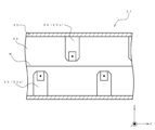
- FIG. 1 is a diagram schematically showing a coating device equipped with a drying system in an embodiment of the present invention.
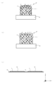
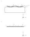
- FIG. FIG. 1 is a diagram for explaining a drying system in an embodiment of the present invention. It is a figure for explaining the state of a coating film and a base material in one embodiment of the present invention. It is a figure for demonstrating the state of a coating film and a base material after drying a coating film by the conventional drying apparatus.
- the three axes of the orthogonal coordinate system are X, Y, and Z, the horizontal direction is expressed as the X-axis direction, and the Y-axis direction, and the direction perpendicular to the XY plane (that is, the vertical direction) is expressed as the Z-axis. Expressed as direction.
- FIG. 1 is a diagram schematically showing a coating device 1 including a drying system 2 in this embodiment.
- FIG. 2 is a diagram for explaining the drying system 2 in this embodiment, and shows a side sectional view of the heating section 21.
- FIG. 3 is a diagram for explaining the state of the coating film M and the base material W in this embodiment, and FIG. 3(a) shows a state in which there is a difference in moisture content between the surface and the inside of the coating film M.
- FIG. 3(b) shows the state of the coating film M with the moisture content adjusted to a predetermined amount
- FIG. 3(c) shows the state of the coating film M and the base material W after passing through the first conveying roll 11e. There is.
- a coating device 1 equipped with a drying system 2 of the present invention includes a conveyance mechanism 11 for conveying a sheet-like base material W, and a coating film M for applying a coating liquid to a predetermined surface of the base material W. (See FIG. 3(c)). Further, the drying system 2 is arranged on the conveyance path of the base material W by the conveyance mechanism 11.
- the predetermined surface of the base material W in this embodiment refers to the surface of the base material W.
- the surface of the base material W here is the surface on which the coating film M is formed by the coating mechanism 12 described later.
- the predetermined surface of the base material W will be referred to as the surface of the base material W.
- the coating device 1 in this embodiment forms a coating film M by the coating mechanism 12 on the surface of the base material W transported by the transportation mechanism 11, and dries this coating film M by the drying system 2.
- the base material W in this embodiment is a metal foil that serves as a battery electrode plate of a lithium ion battery, and aluminum foil or the like is used when forming a positive electrode, and copper foil or the like is used when forming a negative electrode.
- This base material W is a belt-shaped sheet that is long in one direction, and is transported by a transport mechanism 11 so as to pass through each part of the coating device 1 .
- the case of manufacturing a negative electrode plate for a battery will be explained as an example.
- the coating liquid in this embodiment includes, for example, active material A (see FIG. 3(a)), binder B (see FIG. 3(a)), and water E (see FIG. (see (a))), and is used as a material for the negative electrode plate (so-called electrode material) of lithium ion batteries.
- active material A see FIG. 3(a)
- binder B see FIG. 3(a)
- water E see FIG. (see (a)
- a coating film M is formed.
- graphite is used as the active material A
- SBR styrene-butadiene rubber
- acetylene black is used as the conductive agent.
- the transport mechanism 11 in this embodiment is for transporting the base material W.
- the conveyance mechanism 11 includes an unwinding roll 11a that unwinds the base material W, a winding roll 11b that winds up the base material W, and a winding roll 11b that winds the base material W unwound from the unwinding roll 11a. It has a transport roll 11c that the substrate W passes through before being wound up on the roll 11b, and a coating roll 11d that guides the base material W to a position where a coating liquid is applied by a coating mechanism 12, which will be described later.
- Each roll included in the transport mechanism 11 is formed in a cylindrical shape, and rotates about the central axis of the cylinder as a rotation axis.
- the rotation of the unwinding roll 11a is controlled by a control unit (not shown), and unwinds the base material W at a predetermined speed.
- the control unit is configured by, for example, a general-purpose computer device.
- the rotation of the take-up roll 11b is driven and controlled by the control unit similarly to the unwind roll 11a, and winds up the base material W while applying a predetermined tension to the base material W.
- the tension here refers to the tension in the transport direction of the base material W (X-axis direction in FIG. 1).
- a plurality of transport rolls 11c are provided as shown in FIG. 1, and are arranged so that the base material W passes through each part of the coating device 1. Some or all of the transport rolls 11c among the plurality of transport rolls 11c are driven and controlled to rotate by a control unit in the same manner as the unwinding roll 11a and the take-up roll 11b, and apply a predetermined tension to the base material W. While transporting the base material W.
- the coating roll 11d is arranged to face a coating mechanism 12, which will be described later. Therefore, the base material W can be transported while maintaining a constant distance from the coating mechanism 12.
- the transport mechanism 11 can transport the base material W at a predetermined speed while applying a predetermined tension to the base material W.
- the coating mechanism 12 in this embodiment is for coating the surface of the substrate W being transported with a coating liquid to form a striped coating M (see FIG. 3(c)).
- Forming the coating film M in a striped shape means that the base material W has a plurality of coating parts T on which the coating film M is formed, and the coating film M is formed between the plurality of coating parts T as shown in FIG. 3(c).
- the coating film M is formed in the width direction of the base material W so as to have an uncoated area N where no coating is formed.
- the application mechanism 12 will be explained using a slit die as an example, but the application mechanism 12 is not limited to the slit die, and may be compatible with application methods such as inkjet application and gravure application, for example. There may be.
- the coating mechanism 12 is formed long along the width direction of the base material W (Y-axis direction in FIG. 1).
- the coating roll 11d described above is arranged at a predetermined interval with respect to the coating mechanism 12 so that the rotation axis direction of the coating roll 11d and the width direction of the coating mechanism 12 are parallel to each other.
- the coating mechanism 12 is connected to the supply path 17 as shown in FIG. It is constituted by a discharge port 15 that opens with the same length as the slit 14 in the direction and discharges the coating liquid. Thereby, the coating liquid stored in the manifold 13 is discharged onto the base material W from the discharge port 15 via the slit 14. Further, the discharge port 15 faces the coating roll 11d with the base material W interposed therebetween. That is, the discharge port 15 faces the base material W on the surface side of the base material W. Thereby, the coating liquid can be applied to the substrate W while keeping the distance between the discharge port 15 and the substrate W constant.
- the coating mechanism 12 is further provided with a shim plate (not shown) for making the coating film M formed on the base material W into a striped shape.
- the shim plate has, for example, a substantially comb shape, and is arranged to divide the slit 14 in the width direction.
- the coating liquid is applied with the slit 14 divided in the width direction by the shim plate, the coating liquid is applied from the part where the shim plate is not present, and the coating liquid is not applied from the part where the shim plate is present.
- the coating film M can be formed in a stripe shape. Note that by changing the shape of this shim plate, the width of the coating film M can be adjusted. That is, the width of the coated portion T and the non-coated portion N in the width direction of the base material W can be adjusted.
- the supply path 17 connects the manifold 13 and the tank 16 in which the coating liquid is stored. Then, the coating liquid is supplied from the tank 16 to the manifold 13 via the supply path 17 by a pump (not shown).
- the coating mechanism 12 having these configurations allows the coating film M to be formed in stripes on the surface of the base material W.
- the drying system 2 in this embodiment is for drying the coating film M formed on the surface of the base material W by the coating mechanism 12.
- the drying system 2 is provided on the downstream side of the coating mechanism 12 on the conveyance path of the base material W by the conveyance mechanism 11, and includes a heating section 21 and a humidity control means 3. .
- the heating unit 21 is for heating the coating film M formed on the base material W. As shown in FIGS. 1 and 2, the heating unit 21 includes a housing 22 and a heating nozzle 23 that is provided inside the housing 22 and sprays gas toward the base material W. .
- the gas here may be, for example, air or an inert gas such as N 2 gas, He gas, or Ar gas. This gas is heated to a high temperature by a supply source (not shown) and then supplied to the heating nozzle 23.
- the housing portion 22 is a box that is elongated in the transport direction of the base material W, and has a space inside the box through which the base material W passes, and an entrance and an entrance through which the base material W enters and exits this space. It has an exit. Then, the base material W on which the coating film M is formed is transported by the transport mechanism 11 so as to pass through the inside of the casing section 22 . Furthermore, the housing section 22 is divided into a plurality of spaces in the transport direction of the base material W (details will be described later).
- the above-described transport roll 11c is not arranged inside the casing section 22 in this embodiment. Therefore, within the housing section 22, the base material W is transported in a floating state.
- a predetermined tension is applied to the base material W by the conveyance roll 11c disposed on the upstream side and the conveyance roll 11c disposed on the downstream side of the casing part 22, and/or as described below.
- the heating nozzle 23 blows hot air from the back side of the base material W to give a lifting force to the base material W, and the conveyance mechanism 11 transports the base material W to pass through the inside of the casing section 22. ing.
- the heating nozzle 23 is for heating the coating film M by spraying high temperature gas onto the base material W.
- This heating nozzle 23 is formed long in the width direction of the base material W, and has a cavity (not shown) which is a space to which high temperature gas is supplied from the supply source as described above, and a high temperature gas supplied to the cavity. It has a blower outlet (not shown) which is a so-called opening for blowing out gas.
- the heating nozzle 23 includes a lower nozzle 23a that is disposed below the base material W in the casing 22 and sprays high-temperature gas onto the back surface of the base material W, and a lower nozzle 23a that is disposed below the base material W in the casing 22.
- a transport roll 11c may be provided to face the heating nozzle 23 with the base material W in between in the casing 22, and the base material W may be supported and transported from below by the transport roll 11c. That is, the base material W may be transported within the casing section 22 without being levitated.
- the heating unit 21 sprays high-temperature gas toward the base material W using the heating nozzle 23 to heat the coating film M, and vaporizes the moisture E contained in the coating film M.
- the coating film M is not completely dried by the humidity control means 3, which will be described later.
- the humidity control means 3 is for adjusting the amount of solvent contained in the coating film M, and includes a control unit that controls the heating operation of the coating film M by the heating unit 21, and a control unit that controls the heating operation of the coating film M by the heating unit 21. It has a slow cooling section (not shown) that slowly cools the film M, a humidifying section 31 shown in FIG. are doing. In addition, the humidity control means 3 in this embodiment adjusts the moisture content of the coating film M.
- control unit is a general-purpose computer, and in this embodiment controls the heating of the coating film M by the heating unit 21.
- This control section controls the temperature of the gas blown out from the heating nozzle 23 provided in each of the plurality of spaces of the housing section 22 divided in the transport direction of the base material W described above. That is, the temperature of the gas sent to each heating nozzle 23 is controlled by the supply source.
- the casing is installed to the extent that the coating film M is not deformed, that is, the difference in the amount of water E contained in the coating film M between the surface and the inside of the coating film M is suppressed as shown in FIG. 3(b).
- the temperature at which the coating film M is heated in each space is controlled so that the coating film M can be passed through the body portion 22.
- each of the plurality of spaces in the housing section 22 will be referred to as a heating zone 24.
- the slow cooling section is for slowly cooling the coating film M heated by the heating section 21.
- This slow cooling section is composed of some heating zones 24 among the plurality of heating zones 24 described above and heating nozzles 23 provided in the heating zones 24.
- the heating zone 24d located at the most downstream position in the conveyance path of the base material W and the heating nozzle 23 provided within the space are used as a slow cooling section.
- the humidifying section 31 is for humidifying the coating film M, and as shown in FIG.
- the first transport roll 11e is located near the first transport roll 11e) and between the housing portion 22 and the first transport roll 11e.
- This humidifying unit 31 is a box having a space inside which the base material W passes, and has an entrance and an exit for the base material W to enter and exit the box. Then, the base material W having the coating film M heated by the heating section 21 is transported by the transport mechanism 11 so as to pass through the humidifying section 31 .
- the humidifying unit 31 in this embodiment includes a filter (not shown) containing water E, a heater (not shown) that heats and evaporates the water E contained in the filter, and a heater (not shown) that sprays water vapor toward the coating film M. It has a so-called heating vaporization type humidifier having a fan. The humidifying unit 31 then sprays water vapor onto the coating film M to humidify the coating film M so that the amount of water contained in the coating film M becomes a predetermined amount. Thereby, the humidifying section 31 can supplement the moisture E vaporized from the surface of the coating film M.
- the amount of water in the coating film M reaches a predetermined amount means that the coating film M is not deformed, that is, there is no difference in the amount of water E contained in the coating film M between the surface and the inside of the coating film M. This refers to a state in which the coating film M contains water E.
- the humidifying operation of the coating film M by the humidifying section 31 is controlled by the control section.
- the humidifying part 31 may adjust the moisture content of the coating film M by filling the inside with humidified air.
- the liquid amount measuring means is for measuring the amount of solvent contained in the coating film M (hereinafter referred to as the water content of the coating film M), and is, for example, an infrared moisture meter or a color difference meter for measuring the amount of solvent contained in the coating film M. Any device that can measure the moisture content of the coating film M without contacting the coating film M may be used.
- this liquid amount measuring means is used in each heating zone 24 of the housing section 22, between the housing section 22 and the humidifying section 31 in the conveyance path of the substrate W, the humidifying section 31, and the area between the humidifying section 31 and the substrate W. They are arranged between the humidifier 31 and the first transport roll 11e on the transport path. Then, the liquid amount measuring means measures the amount of water in the coating film M at each of the above-mentioned parts, and sends the results of this measurement to the above-mentioned control section.
- the control unit operates to adjust the moisture content of the coating film M by the humidity control unit 3 so that the moisture content of the coating film M becomes a predetermined moisture content based on the measurement result sent by the liquid volume measuring unit.
- Set the humidity control parameter which is the parameter that controls the humidity.
- the humidity control parameter here is, for example, data sent from the control unit to the humidifying unit 31 in order to set the amount of water vapor sprayed onto the coating film M by the humidifying unit 31.
- the control unit in this embodiment immediately feeds back the measurement results sent by the liquid amount measuring means. That is, after measuring with the liquid amount measuring means, humidity control parameters are immediately set based on the measurement results, and the moisture content of the coating film M on the substrate W being conveyed is adjusted by the humidity control means 3. let Thereby, the humidity control means 3 adjusts the moisture content of the coating film M to a predetermined amount.
- the humidity control means 3 adjusts the moisture content of the coating film M on the base material W to a predetermined amount when the base material W that has passed through the housing section 22 comes into contact with the first conveyance roll 11e.
- the coating film M formed on the base material W dries naturally before the base material W is wound up on the take-up roll 11b.
- a heater for assisting drying of the coating film M may be provided between the transport roll 11e and the take-up roll 11b. In this case, the heater dries the coating film M at a drying speed that does not deform the coating film M.
- the drying system 2 in this embodiment further includes an evaluation means for evaluating the state of the base material W after contacting with the first conveyance roll 11e.
- the evaluation means includes an imaging section (not shown), which is a so-called camera that takes an image of the base material W, and an evaluation section (not shown) that evaluates the state of the base material W based on the image taken by the imaging section.
- the evaluation section is one function of the control section, and will be referred to as a control section in the following description.
- This evaluation means images the base material W using the imaging section, and compares the captured image data with image data of the base material W in a normal state prepared in advance in the control section by the control section. Determine whether the condition is normal or not.
- the state in which the state of the base material W is normal refers to the state of the base material W in which the state of the base material W exceeds the standard of the state of the base material W as a normal state set in advance in the control unit. In the embodiment, this means that the base material W has no wrinkles and is not deviated from the position where it should be transported by the transport mechanism 11.
- control unit associates the evaluation result by the evaluation means, the parameters related to this evaluation result, and the measurement result by the liquid amount measuring means and accumulates them as data.
- the parameters related to the evaluation results mentioned here are, for example, heating parameters set to heat the coating film M by the heating unit 21, and parameters set to adjust the moisture content of the coating film M by the humidity control means 3.
- the control section performs an evaluation based on the accumulated data before applying the coating liquid by the coating mechanism 12, heating the coating film M by the heating section 21, and adjusting the moisture content of the coating film M by the humidity control means 3. Predicting instrumental assessment results. Then, the control unit sets appropriate application parameters, heating parameters, and adjustment based on the accumulated data so that the actual evaluation result is at least higher than the condition of the base material W than the above-mentioned criteria with respect to the predicted evaluation result. Select humidity parameters. For example, the control unit detects that the amount of water contained in the coating film M does not meet the predetermined amount due to the fact that the humidity included in the environmental parameters is relatively lower than normal.
- each parameter for making the water content of the coating film M satisfy a predetermined amount so that the condition of the base material W exceeds the standard can be selected.
- the drying system 2 can bring the state of the base material W to a state equal to or higher than the standard. That is, the base material W can be made free of wrinkles and misalignment.
- each parameter by the control unit may be performed by artificial intelligence.
- artificial intelligence may perform learning from data accumulated in the control unit, and automatically select each optimal parameter based on the learning.
- the coating film M is composed of fine powder such as an active material A, a binder B, and a conductive additive. Since the coating film M is composed of powder in this way, pores H (see FIG. 3(b)), which are gaps between the powders, are formed in the coating film.
- the coating film M dries in order from the surface to the inside, so as shown in FIG. 3(a), the coating film M
- the amount of water E is small compared to the inside of the . Therefore, as shown in FIG.
- the size of the pores H1 on the surface of the coating film M with a small amount of water E is smaller than the pores H2 on the inside of the coating film M with a large amount of water E. becomes smaller. That is, on the surface of the coating film M, the above-mentioned gaps between the powder particles become smaller. This causes deviation in the position of the powder in the coating film M. As a result, the coating film M is deformed into a curved shape as shown in FIG. 4(a), for example.
- the drying system 2 in this embodiment has a humidity control means 3, and when the base material W comes into contact with the first conveyance roll 11e, The amount of water contained in the coating film M is adjusted so that the coating film M contains a predetermined amount of water E. Therefore, it is possible to prevent a difference in moisture content between the surface and the inside of the coating film M, thereby preventing the base material W from coming into contact with the first conveyance roll 11e while the coating film M is deformed. be able to. This can prevent wrinkles from forming on the base material W. Therefore, even if the coating film M is heated, it is possible to prevent wrinkles from forming on the base material W.
- the control unit controls each heating zone 24 of the heating unit 21 so that there is no difference in the amount of water contained in the coating film M between the surface and inside of the coating film M.
- the heating operation of the coating film M in is controlled. Therefore, as shown in FIG. 3(b), it is possible to suppress the difference in moisture content between the surface and the inside of the coating film M, and the difference between the pores H2 on the surface of the coating film M and the moisture content inside the coating film M can be suppressed. It is possible to suppress differences in the size of the pores H1 . From this, deformation of the coating film M can be suppressed.
- the humidifying section 31 humidifies the coating film M on the base material W after passing through the housing section 22, deformation of the coating film M can be further suppressed. I can do it. Specifically, as water E evaporates from the surface of the coating film M after passing through the casing 22, as shown in the coating film M shown in FIG.
- the humidifying unit 31 adds water E to the surface of the coating film M where the amount of water has decreased so as to supplement the vaporized water E. Therefore, as shown in FIG. 3(b), it is possible to prevent a difference in moisture content between the surface and the inside of the coating film M. Thereby, it is possible to prevent the coating film M from being deformed during the time from the housing portion 22 to the first conveyance roll 11e. Therefore, deformation of the coating film M can be further suppressed.
- the humidifying unit 31 can adjust the moisture content of the coating film M in the vicinity of the first conveyance roll 11e, when the base material W and the first conveyance roll 11e come into contact, Deformation of the coating film M can be reliably prevented. That is, it is possible to prevent wrinkles from forming on the base material W when the base material W and the first transport roll 11e come into contact with each other.
- the humidity control means 3 in this embodiment has a slow cooling section, and the slow cooling section slowly cools the coating film M before the base material W passes through the housing section 22 to reduce the temperature of the coating film M. Since the temperature is lowered, at least the temperature of the coating film M can be made lower than the temperature when it was heated by the heating section 21. Since the coating film M absorbs moisture E more easily in a low temperature state than in a high temperature state, it easily absorbs and absorbs moisture E in the atmosphere and moisture E sprayed by the humidifying section 31. Become. That is, it becomes easier to control the moisture content of the coating film M to a predetermined amount. Thereby, deformation of the coating film M can be further suppressed.
- the humidity control means 3 in this embodiment has a liquid amount measuring means, and the measurement result by the liquid amount measuring means can be immediately fed back by the control section to the adjustment of the moisture content of the coating film M by the humidity control means 3. can. That is, the control unit can immediately reset suitable humidity control parameters based on the measurement result by the liquid amount measuring means, and therefore can easily adjust the moisture content of the coating film M to a predetermined amount.
- the drying system 2 since the drying system 2 includes a control section and an evaluation means, it is possible to easily bring the state of the base material W into a state equal to or higher than the standard.
- the control unit stores the evaluation result by the evaluation means, the parameter related to this evaluation result, and the measurement result by the liquid amount measuring means as data, and controls the application liquid by the application mechanism 12. Before coating, heating the coating film M by the heating unit 21, and adjusting the moisture content of the coating film M by the humidity control unit 3, the evaluation result by the evaluation unit is predicted based on the accumulated data.
- control unit sets appropriate coating parameters, heating parameters, and adjustment based on the accumulated data so that the actual evaluation result is at least higher than the condition of the base material W compared to the predicted evaluation result.
- Each parameter such as the humidity parameter can be selected. Thereby, the state of the base material W can be easily brought into a state equal to or higher than the standard.
- the drying system 2 is used to manufacture a battery plate for a negative electrode, but it may also be used for manufacturing a battery plate for a positive electrode.
- the humidity control means 3 adjusts the moisture content of the coating film M, but the present invention is not limited to this, and the solvent contained in the coating film M is not water, for example, NMP (N-methyl-pyrrolidone) solvent, the humidity control means 3 adjusts the amount of NMP solvent contained in the coating film M. In this case, the humidifying section 31 adds the NMP solvent to the coating film M.
- NMP N-methyl-pyrrolidone
- the humidity control means 3 has both the slow cooling section and the humidification section 31, but it is not necessary to have either one or both of them, and at least the control It is preferable that the heating unit 21 has a configuration in which the heating of the coating film M by the heating unit 21 is controlled so that there is no difference in moisture content between the surface and the inside of the coating film M.
- the humidity control means 3 does not include the slow cooling section and the humidifying section 31, and only controls the heating section 21 by the control section, so that when the substrate W comes into contact with the first conveyance roll 11e, The upper coating film M may be adjusted to have a predetermined moisture content.
- the liquid amount measuring means is an infrared moisture meter or a color difference meter
- a non-contact displacement meter may be used.
- the amount of deformation of the coating film M and the amount of liquid contained in the coating film M are stored in the control unit in advance, and the amount of deformation of the coating film M is measured by a displacement meter, so that the amount of liquid contained in the coating film M is stored in advance. measure the amount of
Landscapes
- Engineering & Computer Science (AREA)
- Textile Engineering (AREA)
- Mechanical Engineering (AREA)
- General Engineering & Computer Science (AREA)
- Drying Of Solid Materials (AREA)
- Coating Apparatus (AREA)
Abstract
塗膜を加熱しても基材に皺が生じることを防ぐことができる乾燥システムを提供することを目的としている。具体的には、ロールツーロールにより搬送する基材の搬送経路上に設けられ、基材を搬送しながら基材に塗布された塗膜を乾燥させる乾燥システムであって、基材に塗布された塗膜を加熱し、塗膜に含まれる溶媒を気化させる加熱部と、塗膜に含まれる溶媒の量を調節する調湿手段と、を備えており、前記調湿手段は、少なくとも搬送される基材が前記加熱部を通過して最初に所定の抱き角をもって接触する第1の搬送ロールと接触するときに、基材上の塗膜に含まれる溶媒が所定量になるよう調節する構成とする。
Description
本発明は、シート状の基材を搬送しながら、基材に形成された塗膜を乾燥する乾燥システムに関するものである。
従来、リチウムイオン電池の電池用極板の製造工程の中には、ロールツーロール方式の搬送装置により搬送されるシート状の基材に対して、活物質、バインダー、導電助剤および溶媒を含む電極材料のスラリーを塗布して塗膜を形成し、形成した塗膜を乾燥装置により乾燥する工程がある。
一般的なロールツーロール方式の搬送装置は、基材を巻き出す巻出ロールと、基材を巻き取る巻取ロールと、巻出ロールから巻き出された基材が巻取ロールに巻き取られるまでに経由する搬送ロールと、を有している(たとえば、下記特許文献1)。そして、搬送装置は、巻出ロール、巻取ロール、および搬送ロールは、基材に所定の張力を付与しながら搬送している。
従来の乾燥装置は、搬送装置による基材の搬送経路上に設けられ、基材が通過する筐体部と、筐体部内に設けられたノズルと、を有している(たとえば、下記特許文献1)。この乾燥装置は、基材に対してノズルの吹き出し口から気体を吹き付けて筐体部内の温度を高めることによって、搬送される基材上の塗膜を加熱し、溶媒を気化させることで塗膜を乾燥させている。
しかし、上記のような従来の乾燥装置では、基材に皺が生じてしまう場合があった。
具体的に説明する。一般的に塗膜は、活物質、バインダー、および導電助剤といった微小な粉体によって構成されている。このように塗膜は粉体により構成されているため、塗膜には粉体同士の隙間である空孔が形成される。そして、塗膜は、乾燥装置により加熱されて乾燥する過程で、表面から内部へと順番に乾燥する。そのため、加熱後の塗膜表面は、塗膜内部と比較して溶媒の量が少ない状態となる。これにより、溶媒の量が多い塗膜内部における空孔と比較して、溶媒の量が少ない塗膜表面における空孔のサイズが小さくなるため、塗膜に変形が生じる(図4(a)を参照)。
そのため、乾燥装置の筐体部を通過した基材が、この基材に対して張力を付与するために所定の抱き角で基材と最初に接触する搬送ロールと接触するときに、この搬送ロールと基材との間で接触しない部分ができる(図4(a)を参照)。この基材の搬送ロールと接触しない部分に空気が巻き込まれることによって、その部分に皺が生じる(図4(b)を参照)。特に基材において塗膜が形成されていない部分である不塗布部は、基材において塗膜が形成されている部分である塗布部よりも強度が弱くなっているため、皺が生じやすくなっている。このように基材に皺が生じた結果、基材に位置ずれが生じたり、基材が破断したりする問題が生じる。
本発明は、上記問題を鑑みてされたものであり、塗膜を加熱しても基材に皺が生じることを防ぐことができる乾燥システムを提供することを目的としている。
上記課題を解決するための本発明の乾燥システムは、ロールツーロールにより搬送する基材の搬送経路上に設けられ、基材を搬送しながら基材に塗布された塗膜を乾燥させる乾燥システムであって、基材に塗布された塗膜を加熱し、塗膜に含まれる溶媒を気化させる加熱部と、塗膜に含まれる溶媒の量を調節する調湿手段と、を備えており、前記調湿手段は、少なくとも搬送される基材が前記加熱部を通過して最初に所定の抱き角をもって接触する第1の搬送ロールと接触するときに、基材上の塗膜に含まれる溶媒が所定量になるよう調節することを特徴としている。
上記乾燥システムによれば、調湿手段を有し、この調湿手段は、搬送される基材が加熱部を通過して最初に所定の抱き角をもって接触する第1の搬送ロールと接触するときに、基材上の塗膜に含まれる溶媒が所定量になるよう塗膜に含まれる溶媒の量を調節するため、塗膜表面と塗膜内部とで塗膜が含む溶媒の量に差が生じて変形することを防ぐことができる。そのため、基材が第1の搬送ロールと接触しても皺の発生を防ぐことができる。したがって、塗膜を加熱しても基材に皺が生じることを防ぐことができる。
また、前記調湿手段は、前記加熱部と前記第1の搬送ロールとの間に位置するよう設けられ、塗膜を加湿する加湿部を有する構成としてもよい。
この構成によれば、第1の搬送ロールの近傍で塗膜に含まれる溶媒の量を調節することができるため、基材と第1の搬送ロールが接触するときに基材上の塗膜が変形していることを確実に防ぐことができる。
また、前記調湿手段は、前記加熱部により加熱された塗膜を徐冷する徐冷部を有している構成としてもよい。
この構成によれば、加熱部により加熱されて高温な状態となっている塗膜の温度を徐冷して下げることによって、塗膜が高温な状態のときよりも溶媒を吸収および吸湿しやすい状態にすることができる。
また、塗膜に含まれる溶媒の量を計測する液量測定手段を備え、前記液量測定手段による測定結果に基づいて前記調湿手段により塗膜に含まれる溶媒の量を調節する構成としてもよい。
この構成によれば、液量測定手段により塗膜に含まれる溶媒の量を測定した結果に基づいて塗膜に含まれる溶媒の量を調節するため、塗膜に含まれる溶媒の量の調節が容易になる。
また、前記第1の搬送ロールを通過した基材の状態を評価する評価手段と、前記評価手段による評価結果と、この評価結果と関係するパラメータのうち、少なくとも前記加熱部により塗膜を加熱するために設定する加熱パラメータと、前記調湿手段により塗膜に含まれる溶媒の量を調節するために設定する調湿パラメータと、を紐づけてデータとして蓄積する制御部と、を備え、前記制御部は、前記加熱部による塗膜の加熱および前記調湿手段による塗膜に含まれる溶媒の量の調節を行う前に、蓄積した前記データをもとに前記評価手段による評価結果を予測し、適した加熱パラメータおよび調湿パラメータを選択する構成としてもよい。
この構成によれば、蓄積したデータをもとに評価手段による評価結果を予測し、蓄積したデータをもとに適した加熱パラメータ、および調湿パラメータを選択するため、基材Wの状態を容易に基準以上の状態にすることができる。
本発明の乾燥システムによれば、塗膜を加熱しても基材に皺が生じることを防ぐことができる。
本発明の一実施形態における乾燥装置について図面を参照しながら説明する。なお、以下の説明では、直交座標系の3軸をX、Y、Zとし、水平方向をX軸方向、Y軸方向と表現し、XY平面と垂直な方向(つまり、鉛直方向)をZ軸方向と表現する。
図1は、本実施形態における乾燥システム2を備える塗布装置1を概略的に示す図である。図2は、本実施形態における乾燥システム2を説明するための図であり、加熱部21の側面断面図を示している。図3は、本実施形態における塗膜Mと基材Wの状態を説明するための図であり、図3(a)は塗膜Mの表面と内部とで水分量に差が生じている状態、図3(b)は水分量が所定量に調節された塗膜Mの状態、図3(c)は第1の搬送ロール11eを通過後の塗膜Mと基材Wの状態を示している。
本発明の乾燥システム2を備えた塗布装置1は、図1に示すようにシート状の基材Wを搬送する搬送機構11と、基材Wの所定面に塗布液を塗布して塗膜M(図3(c)を参照)形成する塗布機構12と、を有している。また、乾燥システム2は、搬送機構11による基材Wの搬送経路上に配置されている。
なお、本実施形態における基材Wの所定面とは基材Wの表面のことである。ここでいう、基材Wの表面とは後述する塗布機構12により塗膜Mが形成される面である。以下、基材Wの所定面を基材Wの表面と呼ぶ。
本実施形態における塗布装置1は、搬送機構11により搬送される基材Wの表面に塗布機構12により塗膜Mを形成し、この塗膜Mを乾燥システム2により乾燥させる。
本実施形態における基材Wは、リチウムイオン電池の電池用極板となる金属箔であり、正極を構成する場合はアルミニウム箔などが用いられ、負極を構成する場合は銅箔などが用いられる。この基材Wは、一方向に長い帯状のシートであり、搬送機構11により塗布装置1を構成する各部を経由するよう搬送される。なお、以下の説明では、負極の電池用極板を製造する場合を例に説明する。
本実施形態における塗布液は、たとえば、活物質A(図3(a)を参照)、バインダーB(図3(a)を参照)、および図示しない導電助剤を溶媒である水分E(図3(a)を参照)により混合させたスラリーのことであり、リチウムイオン電池の負極の電池用極板の材料(所謂、電極材料)として用いられる。この塗布液を基材Wに塗布することで、塗膜Mが形成される。なお、本実施形態では、活物質Aには黒鉛(グラファイト)、バインダーBにはSBR(スチレン・ブタジエンゴム)、導電助剤にはアセチレンブラックを用いる。
本実施形態における搬送機構11は、基材Wを搬送するためのものである。搬送機構11は、図1に示すように基材Wを巻き出す巻出ロール11aと、基材Wを巻き取る巻取ロール11bと、巻出ロール11aから巻き出された基材Wが巻取ロール11bに巻き取られるまでに経由する搬送ロール11cと、後述する塗布機構12により塗布液を塗布する位置に基材Wを案内する塗布ロール11dと、を有している。この搬送機構11が有する各々のロールは、円柱状に形成され、この円柱の中心軸を回転軸として回転する。
巻出ロール11aは、図示しない制御部により回転を駆動制御され、所定の速度で基材Wを巻き出す。制御部は、たとえば、汎用のコンピュータ装置によって構成されている。また、巻取ロール11bは、巻出ロール11aと同様に制御部により回転を駆動制御され、基材Wに所定の張力を付与しながら基材Wを巻き取る。なお、ここでいう張力は、基材Wの搬送方向(図1におけるX軸方向)の張力のことである。
搬送ロール11cは、図1に示すように複数設けられ、基材Wが塗布装置1を構成する各部を経由するよう配置されている。この複数の搬送ロール11cのうち一部、またはすべての搬送ロール11cは、巻出ロール11aおよび巻取ロール11bと同様に制御部により回転を駆動制御され、基材Wに所定の張力を付与しながら基材Wを搬送する。
塗布ロール11dは、図1に示すように後述する塗布機構12と対向するよう配置されている。そのため、塗布機構12と一定間隔を保ちながら基材Wを搬送することができる。
これら構成により、搬送機構11は、所定の張力を基材Wに付与しながら基材Wを所定の速度で搬送することができる。
本実施形態における塗布機構12は、搬送される基材Wの表面に塗布液を塗布してストライプ状に塗膜M(図3(c)を参照)を形成するためのものである。ストライプ状に塗膜Mを形成するとは、図3(c)に示すように基材Wが、塗膜Mが形成された複数の塗布部Tと、複数の塗布部Tの間に塗膜Mが形成されていない不塗布部Nを有するよう基材Wの幅方向に塗膜Mを形成することである。なお、本実施形態では塗布機構12が、スリットダイであるものを例に説明するが、塗布機構12はスリットダイに限らず、たとえば、インクジェット塗布用やグラビア塗布用の塗布方式に対応するものであってもよい。
塗布機構12は、基材Wの幅方向(図1におけるY軸方向)に沿って長く形成されている。ここで、前述した塗布ロール11dが、塗布機構12に対して、塗布ロール11dの回転軸方向と塗布機構12の幅方向とが平行になるよう所定の間隔を空けて配置されている。
また、塗布機構12は、図1に示すように供給路17に接続され、幅方向に長く塗布液を溜める空間であるマニホールド13と、このマニホールド13と繋がった幅方向に広いスリット14と、幅方向においてスリット14と同一の長さで開口し、塗布液を吐出する吐出口15により構成される。これにより、マニホールド13に溜められた塗布液がスリット14を経由して、吐出口15から基材Wに吐出される。また、吐出口15は、塗布ロール11dと基材Wを挟んで対向している。すなわち、吐出口15は基材Wの表面側で基材Wと対向している。これにより、吐出口15と基材Wとの間隔を一定に保った状態で、基材Wに塗布液を塗布することができる。
そして、塗布機構12には、基材Wに形成する塗膜Mをストライプ状にするための図示しないシム板がさらに設けられている。シム板は、たとえば、略櫛型状を有しており、スリット14を幅方向に分割するよう配置されている。このシム板によりスリット14を幅方向に分割した状態で塗布液を塗布すると、シム板がない部分から塗布液が塗布され、シム板がある部分から塗布液が塗布されないようになる。これにより、塗膜Mをストライプ状に形成することができる。なお、このシム板の形状を変更することで、塗膜Mの幅を調節することができるようになっている。すなわち、基材Wの幅方向における塗布部Tと不塗布部Nの幅を調節することができる。
供給路17は、マニホールド13と塗布液が貯留されているタンク16を接続している。そして、図示しないポンプによりタンク16から供給路17を介してマニホールド13に塗布液を供給する。
これらの構成を有する塗布機構12によって、基材Wの表面にストライプ状に塗膜Mを形成することができる。
本実施形態における乾燥システム2は、塗布機構12により基材Wの表面に形成された塗膜Mを乾燥させるためのものである。乾燥システム2は、図1に示すように搬送機構11による基材Wの搬送経路上において塗布機構12よりも下流側に設けられ、加熱部21と、調湿手段3と、を有している。
加熱部21は、基材Wに形成された塗膜Mを加熱するためのものである。この加熱部21は、図1および図2に示すように筐体部22と、筐体部22の内部に設けられ、基材Wに向けてガスを吹き付ける加熱ノズル23と、を有している。ここでいうガスは、たとえば、空気であってもよいし、N2ガスやHeガス、Arガスのような不活性ガスであってもよい。このガスは、図示しない供給源により高温に加熱されてから加熱ノズル23に供給される。
筐体部22は、基材Wの搬送方向に長く形成された箱体であり、この箱体の内部に基材Wが通過する空間と、この空間に基材Wが出入りするための入口および出口を有している。そして、塗膜Mが形成された基材Wが搬送機構11により筐体部22内を通過するよう搬送される。また、筐体部22は、基材Wの搬送方向において複数の空間に分けられている(詳細は後述する)。
なお、本実施形態における筐体部22内には、前述した搬送ロール11cが配置されていない。そのため、筐体部22内では、基材Wは浮いた状態で搬送される。これに対して、本実施形態では、筐体部22よりも上流側に配置された搬送ロール11cと下流側に配置された搬送ロール11cにより基材Wに所定の張力を付与、または/および後述する加熱ノズル23により基材Wの裏面側から熱風を吹き付けることで基材Wに揚力を付与した状態で、搬送機構11により基材Wが搬送されて筐体部22内を通過するようになっている。
加熱ノズル23は、基材Wに高温のガスを吹き付けることにより塗膜Mを加熱するためのものである。この加熱ノズル23は、基材Wの幅方向に長く形成されており、前述したように供給源から高温のガスを供給される空間である図示しない空洞部と、空洞部に供給された高温のガスを吹き出す所謂開口である図示しない吹出口と、を有している。
この加熱ノズル23は、筐体部22内で基材Wの下方に配置されて基材Wの裏面に高温のガスを吹き付ける下側ノズル23aと、筐体部22内で基材Wの上方に配置されて基材Wの表面に高温のガスを吹き付ける上側ノズル23bとがあり、これら下側ノズル23aと上側ノズル23bは、基材Wの搬送方向に交互に配置されている。そのため、基材Wに揚力が付与されて基材Wが浮揚した状態で、基材Wは略直線方向に搬送される。このように略直線的に基材Wを搬送させることにより、基材Wを浮揚させた状態であっても所定の方向に正確に搬送することができる。なお、筐体部22内で加熱ノズル23と基材Wを挟んで対向するように搬送ロール11cを設け、この搬送ロール11cにより基材Wを下側から支持、搬送してもよい。すなわち、筐体部22内で基材Wを浮揚させずに搬送してもよい。
これら構成により、加熱部21は、加熱ノズル23により基材Wに向かって高温のガスを吹き付けて塗膜Mを加熱し、塗膜Mに含まれる水分Eを気化させている。ここで、後述する調湿手段3により塗膜Mを完全には乾燥させない。
調湿手段3は、塗膜Mに含まれる溶媒の量を調節するためのものであり、加熱部21による塗膜Mの加熱動作を制御する制御部と、加熱部21により加熱されている塗膜Mを徐冷する図示しない徐冷部と、塗膜Mを加湿する図1に示す加湿部31と、塗膜Mに含まれる溶媒の量を測定する図示しない液量測定手段と、を有している。なお、本実施形態における調湿手段3は、塗膜Mの水分量を調節する。
制御部は、前述したように汎用のコンピュータであり、本実施形態では加熱部21による塗膜Mの加熱を制御している。この制御部は、前述した基材Wの搬送方向において分けられた筐体部22の複数の空間のそれぞれに設けられた加熱ノズル23から吹き出すガスの温度を制御している。すなわち、供給源により各加熱ノズル23に送るガスの温度を制御している。そして、塗膜Mに変形が生じない程度、すなわち図3(b)に示すように塗膜Mの表面と内部とで生じる塗膜Mに含まれる水分Eの量の差を抑えた状態で筐体部22を通過させることができるよう、各空間において塗膜Mを加熱する温度を制御する。以下の説明では、筐体部22の複数の空間のそれぞれを加熱ゾーン24と呼ぶ。
徐冷部は、加熱部21により加熱されている塗膜Mを徐冷するためのものである。この徐冷部は、前述した複数の加熱ゾーン24のうち一部の加熱ゾーン24と、その加熱ゾーン24に設けられた加熱ノズル23により構成される。本実施形態では、基材Wの搬送経路において最も下流に位置する加熱ゾーン24dと、その空間内に設けられた加熱ノズル23を徐冷部とする。
この徐冷部では、供給源から加熱していない低温のガスを加熱ゾーン24d内の加熱ノズル23に供給し、この低温のガスを加熱ノズル23により塗膜Mに吹き付けるようになっている。そのため、加熱ゾーン24a、加熱ゾーン24b、および加熱ゾーン24c内で、加熱されてきた塗膜Mの温度を下げることができる。すなわち、筐体部22を通過する直前に塗膜Mの温度を低くすることができる。これにより、塗膜Mは、加熱ゾーン24a、加熱ゾーン24b、および加熱ゾーン24c内で加熱されて高温な状態になっているときよりも、水分Eを吸収および吸湿しやすい状態になる。なお、徐冷部による塗膜Mの徐冷動作は、前述した制御部により制御される。
加湿部31は、塗膜Mを加湿するためのものであり、図1に示すように筐体部22を通過した基材Wが所定の抱き角をもって最初に接触する搬送ロール11c(以下、第1の搬送ロール11eと呼ぶ)の近傍、かつ筐体部22と第1の搬送ロール11eとの間に位置するよう配置されている。
この加湿部31は、内部に基材Wが通過する空間を有する箱体であり、この箱体内に基材Wが出入りするための入口および出口を有している。そして、加熱部21に加熱されたあとの塗膜Mを有する基材Wが搬送機構11により加湿部31内を通過するよう搬送される。
また、本実施形態における加湿部31は、水分Eを含んだ図示しないフィルターと、フィルターが含む水分Eを加熱して蒸発させる図示しないヒーターと、水蒸気を塗膜Mに向かって吹き付けるための図示しないファンと、を有する所謂加熱気化式の加湿器を有している。そして、加湿部31は、塗膜Mに含まれる水分量が所定量になるよう塗膜Mに対して水蒸気を吹き付け、塗膜Mを加湿する。これにより、加湿部31は、塗膜Mの表面から気化した水分Eを補うことができる。なお、塗膜Mの水分量が所定量になるとは、塗膜Mが変形しない程度、すなわち、塗膜Mの表面と内部とで塗膜Mに含まれる水分Eの量に差が生じないように、塗膜Mが水分Eを含んでいる状態をいう。また、加湿部31による塗膜Mの加湿動作は制御部により制御される。なお、加湿部31は、内部に加湿空気を充満させることで塗膜Mの水分量を調節してもよい。
液量測定手段は、塗膜Mに含まれる溶媒の量(以下、塗膜Mの水分量と呼ぶ)を測定するためのものであり、たとえば、赤外線式水分計や色差計のような塗膜Mに接触することなく塗膜Mの水分量を測定できるものであればよい。この液量測定手段は、本実施形態では、筐体部22の各加熱ゾーン24、基材Wの搬送経路における筐体部22と加湿部31との間、加湿部31、および基材Wの搬送経路における加湿部31と第1の搬送ロール11eとの間のそれぞれに配置される。そして、液量測定手段は、前述した各部における塗膜Mの水分量を測定し、この測定による結果を前述した制御部に送る。
制御部は、液量測定手段により送られた測定結果に基づいて、塗膜Mの水分量が所定の水分量になるように調湿手段3による塗膜Mの水分量を調節するための動作を制御するパラメータである調湿パラメータを設定する。ここでいう調湿パラメータとは、たとえば、加湿部31により塗膜Mに吹き付ける水蒸気の量を設定するために制御部から加湿部31へ送るデータのことである。本実施形態における制御部は、液量測定手段により送られた測定結果をただちにフィードバックする。すなわち、液量測定手段による測定を行ったあとに、ただちにその測定結果にもとづいて調湿パラメータの設定を行い、搬送中の基材W上の塗膜Mの水分量を調湿手段3により調節させる。これにより、調湿手段3は、塗膜Mの水分量を所定量に調節する。
これら構成により、調湿手段3は、筐体部22を通過した基材Wが第1の搬送ロール11eと接触するときに、基材W上の塗膜Mの水分量を所定量になるように調節することができる。そして、基材Wが第1の搬送ロール11eと接触したあと、基材W上に形成された塗膜Mは、基材Wが巻取ロール11bに巻き取られるまでに自然に乾燥する。なお、搬送ロール11eと巻取ロール11bの間に塗膜Mの乾燥を補助するヒーターを設けてもよい。この場合、ヒーターは、塗膜Mが変形しない乾燥速度で塗膜Mを乾燥させていく。
また、本実施形態における乾燥システム2は、第1の搬送ロール11eと接触したあとの基材Wの状態を評価する評価手段をさらに備えている。評価手段は、基材Wを撮像する所謂カメラである図示しない撮像部と、撮像部により撮像した画像に基づいて基材Wの状態を評価する図示しない評価部と、を有している。なお、本実施形態では、評価部を制御部の一つの機能とし、以下の説明では制御部と呼ぶ。
この評価手段は、撮像部により基材Wを撮像し、この撮像した画像データと制御部に予め用意された正常な状態の基材Wの画像データとを制御部によって比較し、基材Wの状態が正常か否かを判定する。ここで、基材Wの状態が正常である状態とは、予め制御部に設定した正常な状態であるとする基材Wの状態の基準を上回った基材Wの状態のことをいい、本実施形態では、基材Wに皺がなく、搬送機構11により搬送されるべき位置からずれていないことをいう。
また、制御部は、評価手段による評価結果と、この評価結果と関係するパラメータと、液量測定手段による測定結果と、を紐づけてデータとして蓄積する。ここでいう、評価結果と関係するパラメータは、たとえば、加熱部21により塗膜Mを加熱するために設定する加熱パラメータと、調湿手段3により塗膜Mの水分量を調節するために設定する前述した調湿パラメータと、塗布機構12により塗布液を塗布するために設定する塗布パラメータと、乾燥システム2を備える塗布装置1が設置されている室内の温度および湿度を含む環境パラメータと、塗布液に含まれる成分の比率、基材Wの材質、および基材Wの幅と厚みを含む材料パラメータのことである。
制御部は、塗布機構12による塗布液の塗布、加熱部21による塗膜Mの加熱、および調湿手段3による塗膜Mの水分量の調節を行う前に、蓄積したデータをもとに評価手段による評価結果を予測する。そして、制御部は、予測した評価結果に対して実際の評価結果が少なくとも基材Wの状態が前述した基準を上回るように、蓄積したデータをもとに適した塗布パラメータ、加熱パラメータ、および調湿パラメータを選択する。たとえば、制御部が、環境パラメータに含まれる湿度が通常時よりも比較的に低いパラメータとなっていたことを要因として、塗膜Mに含まれる水分量が所定量を満たさずに基材Wの状態が基準を下回ることを予測した場合、一部または全部のパラメータを変更して再評価を行い、基準を上回るまでパラメータの変更と評価を繰り返し行う。これにより、基材Wの状態が基準を上回るように塗膜Mの水分量を所定量に満たさせるための各パラメータを選択することができる。
この構成により、乾燥システム2は、基材Wの状態を基準以上の状態にすることができる。すなわち、基材Wに皺や位置ずれがない状態にすることができる。
また、制御部による各パラメータの選択は人工知能によって行ってもよい。具体的には、制御部に蓄積されるデータから人工知能が学習を行い、それをもとに自動で最適な各パラメータを選択するようにしてもよい。
このように上記実施形態における乾燥システム2によれば、塗膜Mを加熱しても基材Wに皺が生じることを防ぐことができる。
具体的に説明する。塗膜Mは、活物質A、バインダーB、および導電助剤といった微小な粉体によって構成されている。このように塗膜Mは粉体により構成されているため、塗膜には粉体同士の隙間である空孔H(図3(b)を参照)が形成される。そして、塗膜Mは、筐体部22内で加熱されて乾燥する過程で、表面から内部の順番に乾燥するため、図3(a)に示すように塗膜Mの表面は、塗膜Mの内部と比較して、水分Eの量が少ない状態となる。そのため、図3(a)に示すように水分Eの量が多い塗膜Mの内部における空孔H2と比較して、水分Eの量が少ない塗膜Mの表面における空孔H1のサイズが小さくなる。すなわち、塗膜Mの表面では、前述した粉体同士の隙間が小さくなる。これにより、塗膜Mにおける粉体の位置に偏りが生じる。その結果、たとえば、図4(a)に示す湾曲したような形状に塗膜Mが変形してしまう。
このように変形した塗膜Mを有する基材Wが、第1の搬送ロール11eに接触すると、図4(a)に示すように第1の搬送ロール11eと接触しない部分が基材Wにできる。この基材Wの搬送ロール11cと接触しない部分に空気が巻き込まれることによって、その部分に皺が生じる(図4(b)を参照)。特に基材Wの不塗布部Nは、塗布部Tよりも強度が弱くなっているため、皺が生じやすくなっている。このように基材Wに皺が生じた結果、基材Wに位置ずれが生じたり、基材Wが破断したりする問題が生じる。
これに対して、本実施形態における乾燥システム2は、調湿手段3を有し、この調湿手段3によって、基材Wが第1の搬送ロール11eと接触するときに、基材W上の塗膜Mが所定量の水分Eを含む状態となるよう塗膜Mに含まれる水分量を調節している。そのため、塗膜Mの表面と内部とで水分量に差が生じることを防ぐことができるため、塗膜Mが変形した状態で、基材Wが第1の搬送ロール11eと接触することを防ぐことができる。これにより、基材Wに皺が生じることを防ぐことができる。したがって、塗膜Mを加熱しても基材Wに皺が生じることを防ぐことができる。
より具体的には、図3(b)に示すように塗膜Mの表面と内部とで塗膜Mに含まれる水分量に差が生じないよう、制御部により加熱部21の各加熱ゾーン24における塗膜Mの加熱動作を制御している。そのため、図3(b)に示すように塗膜Mの表面と内部の水分量に差が生じることを抑制することができ、塗膜Mの表面における空孔H2と塗膜Mの内部における空孔H1のサイズに差が生じることを抑制することができる。これより、塗膜Mの変形を抑制することができる。
そして、本実施形態では、筐体部22を通過後の基材W上の塗膜Mに対して加湿部31により塗膜Mを加湿しているため、より塗膜Mの変形を抑制することができる。具体的には、筐体部22を通過後に図3(a)に示す塗膜Mのように塗膜Mの表面から水分Eが気化することで、塗膜Mの内部と比較して水分量が少なくなった塗膜Mの表面に対して、加湿部31は気化した水分Eを補うように水分Eを添加している。そのため、図3(b)に示すように塗膜Mの表面と内部で水分量に差が生じることを防ぐことができる。これにより、筐体部22から第1の搬送ロール11eに到達するまでに間に塗膜Mが変形することを防ぐことができる。したがって、塗膜Mの変形をより抑制することができる。
また、加湿部31は、第1の搬送ロール11eの近傍で塗膜Mの水分量を調節することができるため、基材Wと第1の搬送ロール11eが接触するときに基材W上の塗膜Mが変形していることを確実に防ぐことができる。すなわち、基材Wと第1の搬送ロール11eが接触したときに基材Wに皺が発生することを防ぐことができる。
また、本実施形態における調湿手段3は、徐冷部を有し、徐冷部により基材Wが筐体部22を通過するまでに塗膜Mを徐冷して塗膜Mの温度を下げているため、少なくとも塗膜Mの温度を加熱部21により加熱されていたときの温度よりも低くすることができる。そして、塗膜Mは高温な状態のときよりも低温の状態のときの方が水分Eを吸収しやすくなるため、大気中の水分Eや加湿部31により吹き付けられる水分Eを吸収および吸湿しやすくなる。すなわち、塗膜Mの水分量を所定量にしやすくなる。これにより、塗膜Mの変形をより抑制することができる。
また、本実施形態における調湿手段3は、液量測定手段を有し、液量測定手段による測定結果を制御部により調湿手段3による塗膜Mの水分量の調節にただちにフィードバックすることができる。すなわち、制御部は、液量測定手段による測定結果に基づいて、適した調湿パラメータをただちに設定し直すことができるため、塗膜Mの水分量を所定量に容易に調節することができる。
また、乾燥システム2は、制御部と評価手段とを備えているため、基材Wの状態を容易に基準以上の状態にすることができる。具体的には、制御部が、評価手段による評価結果と、この評価結果と関係するパラメータと、液量測定手段による測定結果と、を紐づけてデータとして蓄積し、塗布機構12による塗布液の塗布、加熱部21による塗膜Mの加熱、および調湿手段3による塗膜Mの水分量の調節を行う前に、蓄積したデータをもとに評価手段による評価結果を予測している。
そのため、制御部は、予測した評価結果に対して実際の評価結果が少なくとも基材Wの状態が前述した基準を上回るように、蓄積したデータをもとに適した塗布パラメータ、加熱パラメータ、および調湿パラメータ等の各パラメータを選択することができる。これにより、基材Wの状態を容易に基準以上の状態にすることができる。
以上、本発明の実施形態について図面を参照しながら詳述したが、各実施形態における構成およびそれらの組み合わせ等は一例であり、本発明の趣旨から逸脱しない範囲内で、構成の追加、省略、置換、およびその他の変更が可能である。たとえば、上記実施形態では、乾燥システム2を負極用の電池用極板の製造に用いることを例に説明したが、正極用の電池用極板の製造に用いてもよい。
また、上記実施形態では、調湿手段3が塗膜Mの水分量を調節することを例に説明したが、これに限られず、塗膜Mに含まれる溶媒が水ではない、たとえば、NMP(N‐メチル‐ピロリドン)溶剤を含むものである場合、調湿手段3は塗膜Mに含まれるNMP溶剤の量を調節する。この場合、加湿部31は、塗膜MにNMP溶剤を添加する。
また、上記実施形態では、調湿手段3が徐冷部と加湿部31の両方を有している例について説明したが、これらどちらか一方、または両方とも有していなくてもよく、少なくとも制御部が塗膜Mの表面と内部とで水分量に差が生じないように、加熱部21による塗膜Mの加熱を制御する構成を有しているとよい。
また、調湿手段3が、徐冷部と加湿部31を備えておらず、制御部による加熱部21の制御のみによって、基材Wが第1の搬送ロール11eと接触するときに基材W上の塗膜Mが所定の水分量になるよう調節してもよい。
また、上記実施形態では、液量測定手段が赤外線式水分計や色差計である例について説明したが、非接触の変位計であってもよい。この場合、予め制御部に塗膜Mの変形量と塗膜Mに含まれる液体の量を記憶させておき、変位計により塗膜Mの変形量を測定することで塗膜Mに含まれる液体の量を測定する。
1 塗布装置
11 搬送機構
11a 巻出ロール
11b 巻取ロール
11c 搬送ロール
11d 塗布ロール
11e 第1の搬送ロール
12 塗布機構
13 マニホールド
14 スリット
15 吐出口
16 タンク
17 供給路
2 乾燥システム
21 加熱部
22 筐体部
23 加熱ノズル
23a 下側ノズル
23b 上側ノズル
24 加熱ゾーン
24a 加熱ゾーン
24b 加熱ゾーン
24c 加熱ゾーン
24d 加熱ゾーン
3 調湿手段
31 加湿部
W 基材
M 塗膜
T 塗布部
N 不塗布部
E 水分
A 活物質
B バインダー
H 空孔
H1 空孔
H2 空孔
11 搬送機構
11a 巻出ロール
11b 巻取ロール
11c 搬送ロール
11d 塗布ロール
11e 第1の搬送ロール
12 塗布機構
13 マニホールド
14 スリット
15 吐出口
16 タンク
17 供給路
2 乾燥システム
21 加熱部
22 筐体部
23 加熱ノズル
23a 下側ノズル
23b 上側ノズル
24 加熱ゾーン
24a 加熱ゾーン
24b 加熱ゾーン
24c 加熱ゾーン
24d 加熱ゾーン
3 調湿手段
31 加湿部
W 基材
M 塗膜
T 塗布部
N 不塗布部
E 水分
A 活物質
B バインダー
H 空孔
H1 空孔
H2 空孔
Claims (5)
- ロールツーロールにより搬送する基材の搬送経路上に設けられ、基材を搬送しながら基材に塗布された塗膜を乾燥させる乾燥システムであって、
基材に塗布された塗膜を加熱し、塗膜に含まれる溶媒を気化させる加熱部と、
塗膜に含まれる溶媒の量を調節する調湿手段と、を備えており、
前記調湿手段は、少なくとも搬送される基材が前記加熱部を通過して最初に所定の抱き角をもって接触する第1の搬送ロールと接触するときに、基材上の塗膜に含まれる溶媒が所定量になるよう調節することを特徴とする乾燥システム。 - 前記調湿手段は、前記加熱部と前記第1の搬送ロールとの間に位置するよう設けられ、塗膜を加湿する加湿部を有することを特徴とする請求項1に記載の乾燥システム。
- 前記調湿手段は、前記加熱部により加熱された塗膜を徐冷する徐冷部を有していることを特徴とする請求項1若しくは請求項2のいずれかに記載の乾燥システム。
- 塗膜に含まれる溶媒の量を計測する液量測定手段を備え、
前記液量測定手段による測定結果に基づいて前記調湿手段により塗膜に含まれる溶媒の量を調節することを特徴とする請求項1から請求項3のいずれかに記載の乾燥システム。 - 前記第1の搬送ロールを通過した基材の状態を評価する評価手段と、
前記評価手段による評価結果と、この評価結果と関係するパラメータのうち、少なくとも前記加熱部により塗膜を加熱するために設定する加熱パラメータと、前記調湿手段により塗膜に含まれる溶媒の量を調節するために設定する調湿パラメータと、を紐づけてデータとして蓄積する制御部と、を備え、
前記制御部は、前記加熱部による塗膜の加熱および前記調湿手段による塗膜に含まれる溶媒の量の調節を行う前に、蓄積した前記データをもとに前記評価手段による評価結果を予測し、適した加熱パラメータおよび調湿パラメータを選択することを特徴とする請求項1から請求項4のいずれかに記載の乾燥システム。
Applications Claiming Priority (2)
| Application Number | Priority Date | Filing Date | Title |
|---|---|---|---|
| JP2022-058050 | 2022-03-31 | ||
| JP2022058050A JP2023149463A (ja) | 2022-03-31 | 2022-03-31 | 乾燥システム |
Publications (1)
| Publication Number | Publication Date |
|---|---|
| WO2023190232A1 true WO2023190232A1 (ja) | 2023-10-05 |
Family
ID=88201566
Family Applications (1)
| Application Number | Title | Priority Date | Filing Date |
|---|---|---|---|
| PCT/JP2023/011978 Ceased WO2023190232A1 (ja) | 2022-03-31 | 2023-03-24 | 乾燥システム |
Country Status (2)
| Country | Link |
|---|---|
| JP (1) | JP2023149463A (ja) |
| WO (1) | WO2023190232A1 (ja) |
Citations (10)
| Publication number | Priority date | Publication date | Assignee | Title |
|---|---|---|---|---|
| US6299685B1 (en) * | 2000-02-11 | 2001-10-09 | Hurletron, Incorporated | Web processing with electrostatic moistening |
| JP2003294364A (ja) * | 2002-03-29 | 2003-10-15 | Fuji Photo Film Co Ltd | 加熱乾燥装置 |
| JP2006138499A (ja) * | 2004-11-10 | 2006-06-01 | Fuji Photo Film Co Ltd | 被乾燥物の乾燥方法及び装置 |
| JP2007042591A (ja) * | 2005-07-07 | 2007-02-15 | Fujifilm Holdings Corp | 固体電解質フィルム及びその製造方法、設備、電極膜複合体、燃料電池 |
| JP2007123239A (ja) * | 2005-09-28 | 2007-05-17 | Honda Motor Co Ltd | 電解質構造体の製造方法 |
| WO2014129214A1 (ja) * | 2013-02-25 | 2014-08-28 | 東レエンジニアリング株式会社 | 塗工乾燥シミュレーション装置および塗工乾燥装置 |
| JP2015035256A (ja) * | 2013-08-07 | 2015-02-19 | 日産自動車株式会社 | 膜電極接合体の製造方法及び製造装置 |
| JP2016168589A (ja) * | 2015-03-11 | 2016-09-23 | 日東電工株式会社 | 塗工膜の製造方法 |
| WO2019224909A1 (ja) * | 2018-05-22 | 2019-11-28 | 富士通株式会社 | パラメータ選択方法、パラメータ選択プログラム、及び情報処理装置 |
| WO2020162205A1 (ja) * | 2019-02-06 | 2020-08-13 | 日本電信電話株式会社 | 最適化装置、方法、及びプログラム |
-
2022
- 2022-03-31 JP JP2022058050A patent/JP2023149463A/ja active Pending
-
2023
- 2023-03-24 WO PCT/JP2023/011978 patent/WO2023190232A1/ja not_active Ceased
Patent Citations (10)
| Publication number | Priority date | Publication date | Assignee | Title |
|---|---|---|---|---|
| US6299685B1 (en) * | 2000-02-11 | 2001-10-09 | Hurletron, Incorporated | Web processing with electrostatic moistening |
| JP2003294364A (ja) * | 2002-03-29 | 2003-10-15 | Fuji Photo Film Co Ltd | 加熱乾燥装置 |
| JP2006138499A (ja) * | 2004-11-10 | 2006-06-01 | Fuji Photo Film Co Ltd | 被乾燥物の乾燥方法及び装置 |
| JP2007042591A (ja) * | 2005-07-07 | 2007-02-15 | Fujifilm Holdings Corp | 固体電解質フィルム及びその製造方法、設備、電極膜複合体、燃料電池 |
| JP2007123239A (ja) * | 2005-09-28 | 2007-05-17 | Honda Motor Co Ltd | 電解質構造体の製造方法 |
| WO2014129214A1 (ja) * | 2013-02-25 | 2014-08-28 | 東レエンジニアリング株式会社 | 塗工乾燥シミュレーション装置および塗工乾燥装置 |
| JP2015035256A (ja) * | 2013-08-07 | 2015-02-19 | 日産自動車株式会社 | 膜電極接合体の製造方法及び製造装置 |
| JP2016168589A (ja) * | 2015-03-11 | 2016-09-23 | 日東電工株式会社 | 塗工膜の製造方法 |
| WO2019224909A1 (ja) * | 2018-05-22 | 2019-11-28 | 富士通株式会社 | パラメータ選択方法、パラメータ選択プログラム、及び情報処理装置 |
| WO2020162205A1 (ja) * | 2019-02-06 | 2020-08-13 | 日本電信電話株式会社 | 最適化装置、方法、及びプログラム |
Also Published As
| Publication number | Publication date |
|---|---|
| JP2023149463A (ja) | 2023-10-13 |
Similar Documents
| Publication | Publication Date | Title |
|---|---|---|
| JP6917329B2 (ja) | 塗布装置 | |
| JP7350750B2 (ja) | ウェブコーティング及びカレンダー加工システム並びに方法 | |
| JP5655769B2 (ja) | 電極の製造方法 | |
| JP6011478B2 (ja) | 電池用電極板の製造装置及び電池用電極板の製造方法 | |
| JP6657135B2 (ja) | 電池製造用装置 | |
| JP2014065000A (ja) | 両面塗工装置、両面塗工方法および塗膜形成システム | |
| JP2015172450A (ja) | 乾燥装置および処理膜形成システム | |
| KR20120082367A (ko) | 전극 제조 장치, 전극 제조 방법 및 컴퓨터 기억 매체 | |
| KR102537218B1 (ko) | 전극시트 이송 장치 및 방법 | |
| JP7554777B2 (ja) | 塗工装置、仕切部材及び塗工方法 | |
| WO2023190232A1 (ja) | 乾燥システム | |
| US20200075962A1 (en) | Manufacturing method and manufacturing apparatus for gas diffusion layer | |
| JP2024142345A (ja) | 乾燥装置 | |
| CN119838826A (zh) | 一种湿面朝上折返式双层涂布设备及涂布方法 | |
| JP2025150138A (ja) | 乾燥装置 | |
| US12224401B2 (en) | System and method of manufacturing lithium ion secondary battery | |
| WO2023037574A1 (ja) | 乾燥装置 | |
| JP2023041509A (ja) | 乾燥装置 | |
| JP2012202650A (ja) | 乾燥装置、および処理装置 | |
| KR20200123016A (ko) | 전지용 세퍼레이터의 제조 시스템 및 제조 방법 | |
| JP2023145188A (ja) | 乾燥装置 | |
| WO2023032250A1 (ja) | 乾燥システム | |
| CA3073569C (en) | Web coating and calendering system and method | |
| JP2020194701A (ja) | 乾燥装置 | |
| JP2009238511A (ja) | 膜電極接合体の製造方法及びその製造装置 |
Legal Events
| Date | Code | Title | Description |
|---|---|---|---|
| 121 | Ep: the epo has been informed by wipo that ep was designated in this application |
Ref document number: 23780242 Country of ref document: EP Kind code of ref document: A1 |
|
| NENP | Non-entry into the national phase |
Ref country code: DE |
|
| 122 | Ep: pct application non-entry in european phase |
Ref document number: 23780242 Country of ref document: EP Kind code of ref document: A1 |