WO2023190216A1 - Analyseur automatisé - Google Patents
Analyseur automatisé Download PDFInfo
- Publication number
- WO2023190216A1 WO2023190216A1 PCT/JP2023/011948 JP2023011948W WO2023190216A1 WO 2023190216 A1 WO2023190216 A1 WO 2023190216A1 JP 2023011948 W JP2023011948 W JP 2023011948W WO 2023190216 A1 WO2023190216 A1 WO 2023190216A1
- Authority
- WO
- WIPO (PCT)
- Prior art keywords
- analysis
- reagent
- section
- automatic analyzer
- item group
- Prior art date
Links
- 238000004458 analytical method Methods 0.000 claims abstract description 234
- 230000007246 mechanism Effects 0.000 claims abstract description 189
- 239000007788 liquid Substances 0.000 claims abstract description 27
- 239000003153 chemical reaction reagent Substances 0.000 claims description 254
- 238000006243 chemical reaction Methods 0.000 claims description 63
- 230000032258 transport Effects 0.000 claims description 13
- 230000001900 immune effect Effects 0.000 claims description 6
- 230000036039 immunity Effects 0.000 claims description 3
- 230000003053 immunization Effects 0.000 abstract 1
- 238000002649 immunization Methods 0.000 abstract 1
- 239000000523 sample Substances 0.000 description 116
- 238000005259 measurement Methods 0.000 description 65
- 238000003756 stirring Methods 0.000 description 37
- 230000007723 transport mechanism Effects 0.000 description 23
- 238000004140 cleaning Methods 0.000 description 21
- 238000001514 detection method Methods 0.000 description 18
- 239000000243 solution Substances 0.000 description 11
- 238000010586 diagram Methods 0.000 description 9
- 238000007599 discharging Methods 0.000 description 8
- 238000009434 installation Methods 0.000 description 6
- 238000002360 preparation method Methods 0.000 description 6
- 238000003860 storage Methods 0.000 description 6
- 239000012295 chemical reaction liquid Substances 0.000 description 5
- 239000006249 magnetic particle Substances 0.000 description 5
- 238000011017 operating method Methods 0.000 description 5
- 239000000538 analytical sample Substances 0.000 description 4
- 238000010790 dilution Methods 0.000 description 3
- 239000012895 dilution Substances 0.000 description 3
- 239000000203 mixture Substances 0.000 description 3
- 238000012545 processing Methods 0.000 description 3
- 210000003371 toe Anatomy 0.000 description 3
- 238000012742 biochemical analysis Methods 0.000 description 2
- 230000007423 decrease Effects 0.000 description 2
- 238000006073 displacement reaction Methods 0.000 description 2
- 230000000694 effects Effects 0.000 description 2
- 239000003792 electrolyte Substances 0.000 description 2
- 230000006870 function Effects 0.000 description 2
- 238000012423 maintenance Methods 0.000 description 2
- 238000000034 method Methods 0.000 description 2
- 238000012986 modification Methods 0.000 description 2
- 230000004048 modification Effects 0.000 description 2
- 238000012546 transfer Methods 0.000 description 2
- 239000011324 bead Substances 0.000 description 1
- 238000005119 centrifugation Methods 0.000 description 1
- 238000011109 contamination Methods 0.000 description 1
- 238000001816 cooling Methods 0.000 description 1
- 230000006866 deterioration Effects 0.000 description 1
- 239000012470 diluted sample Substances 0.000 description 1
- 238000009826 distribution Methods 0.000 description 1
- 238000007689 inspection Methods 0.000 description 1
- 239000004973 liquid crystal related substance Substances 0.000 description 1
- 230000008569 process Effects 0.000 description 1
- 230000001737 promoting effect Effects 0.000 description 1
- 230000009467 reduction Effects 0.000 description 1
- 238000010998 test method Methods 0.000 description 1
- 238000012360 testing method Methods 0.000 description 1
- 238000011282 treatment Methods 0.000 description 1
- 238000005406 washing Methods 0.000 description 1
Images


Classifications
-
- G—PHYSICS
- G01—MEASURING; TESTING
- G01N—INVESTIGATING OR ANALYSING MATERIALS BY DETERMINING THEIR CHEMICAL OR PHYSICAL PROPERTIES
- G01N35/00—Automatic analysis not limited to methods or materials provided for in any single one of groups G01N1/00 - G01N33/00; Handling materials therefor
Definitions
- the present invention relates to an automatic analyzer.
- Patent Document 1 describes an automatic analyzer in which at least two or more different measurement units, each of which performs a different type of analysis, are constructed into a single device configuration.
- the system configuration is a combination of a device configuration specialized for each item measurement and a sample input section. For this reason, there is a problem in that it can be used only in large-scale/medium-sized laboratories where the area occupied by the automatic analyzer in the site area of the laboratory can be widely used.
- the product is a family product with a conventional product
- the operating feel, analysis principles, and operating methods of the conventional device be the same or similar, from the perspective of reducing the burden on the operator.
- the mechanical layout and system configuration are mostly specialized for each operation. Therefore, it is necessary to appropriately arrange or simplify the mechanical layout according to each item while inheriting the operational feel of the conventional device.
- the present invention provides an automatic analysis device that inherits the operational feel of the conventional device and realizes a mechanical layout according to each item.
- the present invention includes a plurality of means for solving the above problems, and to give one example, a first analysis section that performs an analysis related to a first analysis item group, and a first analysis section that performs an analysis related to a first analysis item group; A second analysis unit that performs analysis related to two analysis item groups, a first mechanism that is commonly used for the first analysis item group and the second analysis item group, and a mechanism that is different from the first mechanism; , a second mechanism commonly used for the first analysis item group and the second analysis item group, and dispensing a first liquid from the first mechanism to the first analysis section and the second analysis section.
- a first dispensing section a second dispensing section that dispenses a second liquid different from the first liquid from the second mechanism to the first analysis section and the second analysis section;
- the left-right direction of the user's standing position is defined as the X-axis
- the direction perpendicular to the X-axis is defined as the Y-axis, along the X-axis, from the left of the standing position
- the analysis unit and the second mechanism are arranged in this order, and the first analysis unit and the second analysis unit are arranged in this order along the Y-axis in the direction away from the standing position.
- a first analysis section that performs an analysis related to a group of biochemical items
- a second analysis section that performs an analysis related to a group of immune items
- a second analysis section that performs an analysis related to a group of biochemical items and a group of immunological items
- a first mechanism that is commonly used, and a second mechanism that is different from the first mechanism and is commonly used for the biochemical item group and the immunological item group and is assumed to be
- the left-right direction of the user's standing position is defined as the X-axis
- the direction perpendicular to the X-axis is defined as the Y-axis, along the X-axis, from the left of the standing position
- the analysis unit and the second mechanism are arranged in this order, and the first analysis unit and the second analysis unit are arranged in this order along the Y-axis in the direction away from the standing position.
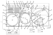
- FIG. 1 is a diagram showing an overview of the overall configuration of an automatic analyzer.
- FIG. 2 is a diagram showing an overview of the automatic analyzer as viewed diagonally from above. A diagram showing an overview of the lower structure of the automatic analyzer.
- FIGS. 1 to 5 An embodiment of the automatic analyzer of the present invention will be described using FIGS. 1 to 5.
- FIG. 1 is a diagram showing an example of a configuration diagram of an automatic analyzer.
- FIG. 2 is a diagram showing an overview of the first analysis and measurement section and the second analysis and measurement section, and
- FIG. 3 is a diagram showing an overview of the first mechanism, the first analysis and measurement section, the second mechanism, and the second analysis and measurement section.
- 4 is a diagram showing an overview of the automatic analyzer as viewed diagonally from above.
- the first mechanism commonly used for the first analysis item group 300 and the second analysis item group 400 is the specimen holding section 4 located in the specimen holding area 100
- the second mechanism commonly used in the second analysis item group 400 is the reagent holding section 16 located in the reagent holding area 200.
- An automatic analyzer 1 shown in FIGS. 1 to 4 is an apparatus for analyzing a sample using a reagent according to a predetermined analysis item, and is composed of an analysis section 2 and a control section 3.
- the analysis section 2 includes a sample holding section 4, a sample information reading section 5, a sample dispensing mechanism 25, a washing tank 26 for the sample dispensing mechanism, a reagent holding section 16, and a first reagent portion.
- the specimen holding unit 4 has a structure capable of holding a plurality of annular specimen containers 23 that contain specimens to be analyzed in the analysis related to the first analysis item group 300 and the analysis related to the second analysis item group 400.
- a sample information reading section 5 is provided around the sample holding section 4 to read information such as a bar code (various information regarding the sample) attached to the sample container.
- the sample information reading section 5 is located at the side edge of the device housing.
- the sample holding section 4 rotates and transports the sample container 23 to the access position of the sample dispensing mechanism 25.
- the sample holding unit 4 includes a sample suction position 24, and immediately before the sample dispensing mechanism 25 aspirates the sample to be analyzed, the sample holding unit 4 rotates and transports the sample container 23 to the sample suction position 24. do.
- the sample holding section 4 partially protrudes from the main frame of the automatic analyzer 1, but it is assumed that it is covered by the cover. It is desirable to do so.
- the specimen holding section 4 may be configured so that the two specimen holding sections 4 can be physically replaced alternately. Samples can also be added or replaced midway through a small window provided in the sample holding section 4. However, it does not have to be constructed by the user himself, and may be transported using a transport mechanism or the like. Further, the sample holding section 4 may have a structure capable of holding a plurality of sample racks capable of holding one or more sample containers 23. Furthermore, the automatic analyzer 1 may be connected to an external sample rack transport mechanism, and the sample racks may be transported to the sample holding section 4.
- the sample dispensing mechanism 25 transfers the sample from the sample container 23 at the sample suction position 24 to the first incubator 35 located at the first analysis sample discharge section 27 of the first analysis and measurement section 301 and from the sample container 23 at the sample suction position 24 to the first incubator 35 located at the first analysis sample discharge section 27 of the first analysis and measurement section 301 .
- It is composed of a rotational drive mechanism, a vertical drive mechanism, and a dispensing probe so as to move above the disposable container 7 located in the analysis sample discharge section 28 and perform sample dispensing.
- the rotational drive mechanism and vertical drive mechanism of the sample dispensing mechanism 25 move between the sample suction position and the sample discharge position, and dispense the sample at the sample suction position 24 into the first incubator 35 or the disposable container 7.
- the aspirated specimen is discharged into the container. After the sample is discharged, it is cleaned in the sample dispensing mechanism cleaning tank 26, and the next sample dispensing operation begins.
- the configuration may be such that each position is accessed by a rotational movement, or the configuration may be such that each position is accessed by a linear movement.
- the reagent holding unit 16 includes a first reagent container containing reagents used for analysis related to the first analysis item group 300 to be reacted in the first incubator 35 and a second analysis item group 400 to be reacted in the disposable container 7. It is a mechanism for holding a plurality of second reagent containers containing reagents used for analysis related to analysis, and includes a reagent disk (omitted for convenience of illustration), reagent container holding positions (first reagent container mounting section 38, It has a second reagent container mounting section 17A, a third reagent container mounting section 17B), and a cover 16A.
- the reagent holding section 16 has a reagent cooling function.
- Reagent container holding positions are arranged in a double ring on the reagent disk, and are configured to hold a plurality of first reagent containers and second reagent containers. The details will be described later. Further, the reagent disk has a rotational drive mechanism, and moves each of the first and second reagent containers to a predetermined position on the circumference by rotational movement.
- the reagent disk rotates before reagent dispensing, and by conveying an appropriate reagent container to the first reagent suction position 37 or the second reagent suction position 36, the first reagent dispensing mechanism 18 or the A two-reagent dispensing mechanism 33 can aspirate reagents necessary for analysis.
- the first reagent container and the second reagent container may each be composed of a plurality of different reagent bottles.
- the automatic analyzer 1 serves as a second dispensing section for dispensing reagents from the reagent holding section 16 to the first analysis and measurement section 301 and the second analysis and measurement section 401, and is for the first analysis item group 300.
- a second reagent dispensing mechanism 33 for discharging into the disposable container 7 is separately provided.
- each of the first reagent dispensing mechanism 18 and the second reagent dispensing mechanism 33 is common, and is composed of a rotational drive mechanism, a vertical drive mechanism, and a dispensing probe.
- the second reagent dispensing mechanism 33 may be configured to be able to aspirate the reagent from the second reagent container while the first reagent dispensing mechanism 18 is aspirating the reagent from the first reagent container. Thereby, it is possible to improve the analysis throughput.
- the first reagent dispensing mechanism 18 and the second reagent dispensing mechanism 33 rotate and descend to the position of a predetermined type of first reagent container or second reagent container in the reagent holding section 16 to aspirate a predetermined amount of reagent. do. After suctioning the reagent, the first reagent dispensing mechanism 18 and the second reagent dispensing mechanism 33 rise.
- the reagent discharge destination for example, the predetermined first incubator 35 in the case of the first reagent dispensing mechanism 18 for biochemical analysis, and the second reagent dispensing position in the case of the second reagent dispensing mechanism 33 for immunological analysis. It rotates and descends into a disposable container 7 for analysis of immune items installed at 31, and discharges each reagent. After the reagent is discharged, it is cleaned in the first reagent dispensing mechanism cleaning tank 19 or the second reagent dispensing mechanism cleaning tank 32, and the next reagent dispensing operation begins.
- a reagent stirring mechanism 34 (also referred to as a stirrer) is set around the reagent holding part 16 as a stirring means for stirring the reagent contained in the second reagent container.
- the reagent stirring mechanism 34 moves to the upper region of the second reagent container containing the magnetic particle solution to be stirred, lowers the magnetic particle stirring element of the reagent stirring mechanism 34, and rotates the stirring element to generate the magnetic particles. Stir the solution.
- the reagent stirring mechanism 34 stirs the magnetic particles immediately before the reagent is dispensed. After stirring, the reagent stirring mechanism is cleaned in a cleaning tank 15.
- the first reaction container transport mechanism 6 has a drive mechanism in the X-axis, Y-axis, and Z-axis directions, and a reaction container gripping mechanism, and has a first tray 7a, a second tray 7b, a reaction container disposal position 8, and a reaction container holding mechanism. 2 incubator 9 and above the second analysis sample discharge section 28.
- the second reaction container transport mechanism 11 has a rotational drive mechanism, a vertical drive mechanism, and a reaction container gripping mechanism, and is a disposable container that accommodates a reaction solution containing a mixture of a sample and a reagent in the analysis related to the second analysis item group 400.
- the container 7 is moved to a stirring position by the second stirring mechanism 10 provided on a rotating orbit, the second analysis sample discharge part 28, the reaction container standby position 29, the second detection part preparation operation mechanism 13, the second reagent discharge position 31, etc. It has a function to move to each reaction container installation position.
- the first reaction container transport mechanism 6 transports one disposable container 7 from the first tray 7 a and the second tray 7 b that accommodate unused disposable containers 7 to the second analytical sample discharge section 28 .
- the sample dispensing mechanism 25 dispenses a predetermined amount of sample into the disposable container 7 installed in the second analysis sample discharge section 28. Thereafter, the disposable container 7 into which the specimen has been discharged is transported to the second reagent discharge position 31 by the reaction container second transport mechanism 11 .
- the second reagent dispensing mechanism 33 dispenses a predetermined amount of R1/R2 reagent into the disposable container 7 installed at the second reagent discharge position 31. Thereafter, the disposable container 7 is moved to the position of the second stirring mechanism 10 by the reaction container second transport mechanism 11, and the liquid mixture in the disposable container 7 is stirred.
- the disposable container 7 After stirring the reaction solution, the disposable container 7 is moved to the second incubator 9 by the reaction container first transport mechanism 6. Here, if dilution is necessary, the disposable container 7 is transported to the dilution position 28a, and the diluted sample is aspirated in the next cycle.
- the disposable container 7 is transported to the reaction container standby position 29 by the reaction container first transport mechanism 6, and when the next reagent dispensing timing comes, the second reaction container transport mechanism 11 transports the disposable container 7 to the reaction container standby position 29. Transport to position 31.
- the Beads reagent is dispensed into the disposable container 7 by the second reagent dispensing mechanism 33, and then the disposable container 7 is transported to the second stirring mechanism 10 by the reaction container second transport mechanism 11 for further stirring. conduct.
- the disposable container 7 is transported to the second incubator 9 by the reaction container first transport mechanism 6.
- the second incubator 9 is temperature-controlled to an appropriate temperature for the purpose of holding the disposable container 7 and promoting the reaction between the specimen and the reagent, and when the reaction process between the specimen and the reagent on the second incubator 9 is completed, the reaction
- the first container transport mechanism 6 transports the disposable container 7 to the reaction container standby position 29 .
- the reaction liquid cleaning displacement mechanism 12 and the second detection section preparation operation mechanism 13 are moved, and the pre-cleaning step is carried out. implement.
- the disposable container 7 is transported to the second stirring mechanism 10 by the second reaction container transport mechanism 11 . Thereafter, the disposable container 7 is transported by the reaction container first transport mechanism 6 to the mixed liquid suction position on the second detection section preparation operation mechanism 13, and the second detection section preparation operation mechanism 13 is moved below the second analysis detection section 14. Move to the reaction liquid suction position provided in , and aspirate the reaction liquid. Thereafter, the reaction solution is sucked into the detection section in the second analysis detection section 14, and the reaction signal is measured.
- the second reaction container transport mechanism 11 transports the disposable container 7 to the reaction container standby position 29, and the first reaction container transport mechanism 6 transports it to the reaction container disposal position 8 for disposal.
- the automatic analyzer 1 of this embodiment has a first analysis sample discharge section 27 in which the first incubator 35 that receives the sample from the sample dispensing mechanism 25 is placed, a second analysis sample discharge section 28 on which a disposable container 7 is placed to receive the reagent dispensed; a second reagent discharge position 31 on which the disposable container 7 is placed to receive the reagent dispensed from the second dispensing section; A reaction container second transport mechanism 11 is provided that transports the disposable container 7 between the second analysis sample discharge section 28, the second analysis measurement section 401, and the second reagent discharge position 31.
- the suction position of the sample dispensing mechanism 25, the first analysis sample discharging section 27, and a second analysis sample discharge section 28 are arranged.
- the first incubator 35 is a mechanism that holds a reaction solution for analysis by the first analysis detection unit 21 that measures the reaction solution in the analysis related to the first analysis item group 300, and like the second incubator 9, it contains specimens and reagents.
- the temperature is controlled at an appropriate temperature to promote the reaction with
- the sample dispensing mechanism 25 dispenses a predetermined amount of a sample into a predetermined first incubator 35 that accommodates a reaction solution containing a mixture of a sample and a reagent in an analysis related to the first analysis item group 300. Thereafter, the first incubator 35 is rotated, and the first incubator 35 from which the specimen has been discharged is moved to the access position of the first reagent dispensing mechanism 18, and the first reagent dispensing mechanism 18 is connected to the first incubator from which the specimen has been discharged. Dispense a predetermined amount of reagent into 35 tubes.
- the first incubator 35 rotates, and the first incubator 35 from which the specimen and reagent have been discharged is moved to the first stirring mechanism 30 installation position, and the specimen and reagent in the first incubator 35 are stirred by the first stirring mechanism 30. be done.
- the first incubator 35 rotates, and the first incubator 35 containing the reaction solution after the reaction is completed is used for a first analysis for analyzing biochemical items of the sample. It is moved to the installation position of the detection unit 21.
- the detection section in the first analysis detection section 21 measures the reaction signal. After the signal measurement, the reaction solution is discharged from the first incubator 35 by the reaction container cleaning mechanism 22.
- electrolyte items may be further installed as the measurement unit 20 that can accompany the biochemical items.
- analysis items that can be added are not limited to electrolyte items, and may be other analysis items.
- the mechanism described above in the automatic analyzer 1 is referred to as the analysis operation section.
- the automatic analyzer 1 includes a control section 3 that controls the operation of each device in the automatic analyzer 1, including the sample holding section 4 and the sample dispensing mechanism 25.
- the control unit 3 may be composed of a computer having a display unit 3a such as a liquid crystal display, an input unit 3b, a storage device, a CPU, a memory, etc., and may be composed of one computer or another computer. It may be configured by a computer, and is not particularly limited.
- the control section 3 at least the display section 3a and the input section 3b are preferably arranged on the side where the specimen holding section 4 is arranged, especially when the specimen is It is desirable to arrange it between the holding part 4 and the second analysis part 400.
- the input unit 3b be movable to a position where the user can easily access it when in use, and to a position that does not obstruct the user's access to various mechanisms around the specimen holding unit 4 when not in use.
- Control of the operation of each device by the control unit 3 is executed based on various programs recorded in the storage device. Note that the control processing of the operations executed by the control unit 3 may be summarized into one program, each may be divided into a plurality of programs, or a combination thereof may be used. Further, part or all of the program may be realized by dedicated hardware or may be modularized.
- a mechanism that can be used in common for the analysis related to the first analysis item group 300 and the analysis related to the second analysis item group 400 (in this example, the sample holding part 4 , the reagent holding section 16, and the sample dispensing mechanism 25), thereby eliminating the need for a dedicated mechanism.
- the mechanical layout maintains the characteristics of the main mechanical layout for each item.
- the layout of the main mechanism of the first analysis item group 300 continuously monitors the reaction process from discharging the sample and reagent to extracting the measurement result, and removes the liquid in the first incubator 35 after measurement.
- the main mechanisms are arranged on the circumference of the first incubator 35, and other main mechanisms are laid out on the circumference of the first incubator 35.
- the main mechanism layout of the second analysis item group 400 is a test method that uses disposable containers 7 for each test item from the viewpoint of preventing contamination between samples.
- the main mechanism is laid out in such a way that the disposable containers 7 can be handled between areas for each functional use such as reagent reaction, reaction liquid measurement, etc.
- the horizontal direction of the assumed user's standing position (Figs. 1 to 3, lower middle side of Fig. 5) as the X-axis
- the direction perpendicular to this X-axis as the Y-axis.
- the sample holding section 4 the first analysis and measurement section 301, and the reagent holding section 16 were arranged in this order.
- the sample input and sample storage area into the automatic analyzer 1 and the reagent input and reagent storage area were placed on the left and right sides of the front side of the apparatus, respectively, for easy access. .
- the first analysis and measurement section 301 and the second analysis and measurement section 401 were arranged in this order along the Y axis in the direction away from the standing position (upper side in FIGS. 1 to 3 and 5).
- the first analysis and measurement section 301 since the first analysis and measurement section 301 has a structure in which the reaction process and various treatments are continuously carried out in the first incubator 35, there are relatively many short units, whereas the second analysis and measurement section 301 Since the section 401 has a structure for delivering the disposable container 7, there are many units, and many of the units and structures are tall overall. Therefore, from the viewpoint of usability, in order to ensure accessibility and visibility, the first analysis and measurement section 301 was laid out on the front side of the central part of the automatic analyzer 1, and the second analysis and measurement section 401 was laid out on the back side.
- the second analysis and measurement section 401 was installed higher than the first analysis and measurement section 301 in the vertical direction. More specifically, the first analysis and measurement section 301 was installed at the same height as the apparatus table surface, whereas the second analysis and measurement section 401 was installed at a higher position from the table surface in the vertical direction.
- a touch panel 3c serving as the display section 3a and input section 3b of the control section 3 was placed between the sample holding section 4 and the second analysis section 400.
- FIG. 5 is a diagram showing an outline of the lower structure of the automatic analyzer.
- the apparatus standing position 44 of the automatic analyzer 1 of the present invention can be located inside the apparatus, compared to the conventional apparatus standing position 43.
- the first reagent container containing the first reagent for the first analysis item group 300 and the second analysis item group 400 is different analysis items. It is desirable that the shape of the second reagent container containing the second reagent for group 400 is different. In this case, it is desirable that the reagent holding section 16 be provided with a dedicated position for holding each reagent container.
- the reagent holding section 16 has a first reagent container mounting section 38 that can hold only the first reagent container containing the first reagent among the reagents as the second liquid, and a first reagent holding section 38 as a reagent holding position.
- a second reagent container mounting portion 17A that can hold only a second reagent container containing a second reagent different in type from the first reagent, and a third reagent that can hold both the first reagent container and the second reagent container. It has a container mounting part 17B.
- Each position of the first reagent container placement portion 38, the second reagent container placement portion 17A, and the third reagent container placement portion 17B is such that only the first reagent container placement portion 38 is located on the inner circumferential side.
- the second reagent container placement portion 17A and the third reagent container placement portion 17B are arranged in a double ring shape alternately on the outer circumferential side.
- first reagent container placement portion 38 on the inner circumference side and the third reagent container placement portion 17B on the outer circumference side are configured such that the longitudinal direction thereof is such that the first reagent dispensing mechanism 18 can easily access the reagent container. It is assumed that the position is not parallel to a line extending radially from the center of the holding part 16.
- the second reagent container placement section 17A is positioned such that its longitudinal direction is not parallel to the longitudinal directions of the first reagent container placement section 38 and the third reagent container placement section 17B. did.
- the operating areas of the first reagent dispensing mechanism 18 and the second reagent dispensing mechanism 33 should interfere with each other. It is desirable not to do so. Also, the distance between the reagent suction position and the reagent discharge position (between the first reagent suction position 37 and the reagent discharge position of the first incubator 35, between the second reagent suction position 36 and the second reagent discharge position 31), (distance) is desirable.
- the rotating shaft 18A of the arm thereof is arranged on the cover 16A of the reagent holding section 16.
- the first reagent container and the second reagent container are provided with a stopper to prevent deterioration of the reagent. Further, the second reagent container containing the second liquid for the second analysis item group 400 may be provided with a cap instead of a stopper.
- the automatic analyzer 1 is equipped with a needle that automatically opens the caps for reagent containers inserted into the device. It is provided in the first reagent dispensing mechanism cleaning tank 19 in a form that is detachable from the dispensing mechanism 18 . Similarly, an opener 46 is provided near the second reagent aspiration position 36 as a mechanism for removing the cap.
- the cleaning tank 19 for the first reagent dispensing mechanism is not located between the first reagent suction position 37 and the reagent discharge position of the first incubator 35, but between the first reagent suction position 37 of the first reagent dispensing mechanism 18 and the reagent discharge position of the first incubator 35. It is arranged around the first incubator 35 on the extension line of the operation locus with the reagent discharge position of the first incubator 35, after the input of the reagent container is recognized, and at a timing that does not overlap with the timing of reagent suction, etc. The first reagent dispensing mechanism 18 grips the needle, opens the cap, and cleans the needle.
- the reagent stirring mechanism 34 is provided, but in order to shorten the operating distance of the reagent stirring mechanism 34 as much as possible, it must be placed at a position that does not overlap with the operating area of the second reagent dispensing mechanism 33 and at the outer periphery of the reagent holder 16. It is desirable to extend from the side to the second reagent suction position 36, which is the stirring position, at the shortest distance. However, in that case, it will be difficult to access the reagent stirring mechanism 34 from the front side of the automatic analyzer 1, and it is expected that maintenance will be troublesome.
- the reagent holding section 16 is provided at a position on the outer periphery on the opposite side to the side where the second reagent suction position 36 is located so as to be on the front side of the automatic analyzer 1. It is assumed that the trajectory straddles most of the reagent holding section 16.
- the operation will take time, but since the operation locus of the reagent stirring mechanism 34 does not overlap with the operation area of the second reagent dispensing mechanism 33, if stirring is necessary, it is necessary to This can be dealt with by moving near the second reagent suction position 36 and waiting at a timing up to this point, and there is almost no problem on the time chart.
- the second analysis sample dispensing unit 28 is used after aspirating the sample. Before moving, it is necessary to pass over the first incubator 35 in addition to the first analysis sample discharge section 27. At this time, in order to prevent the sample from dripping onto the first incubator 35, at least the first analysis sample discharge section 27 and the first analysis sample discharge section 27 are It is desirable that a cover be provided above the area between the two analytical sample discharge sections 28.
- the second analysis sample discharging unit 28 Although it is possible to access the second analysis sample discharging unit 28 without passing over the first incubator 35, the operating distance becomes longer, and the first tray 7a and the second tray 7b Although it is necessary to pass over the top of the first tray 7a and the second tray 7b, similar measures such as covering the first tray 7a and the second tray 7b must be taken, so in order to shorten the travel distance, the second analysis It is desirable that the trajectory of movement to the sample discharge section 28 passes over the first incubator 35 .
- the automatic analyzer 1 of the present embodiment described above includes the sample dispensing mechanism 25 that dispenses the first liquid from the first mechanism to the first analysis and measurement section 301 and the second analysis and measurement section 401, and the sample dispensing mechanism 25 that dispenses the first liquid from the first mechanism to the first analysis and measurement section 301 and the second analysis and measurement section 401.
- a second dispensing section that dispenses a second liquid different from the first liquid to the analysis and measurement section 301 and the second analysis and measurement section 401, or the first analysis and measurement that performs analysis related to a group of biochemical items.
- the X-axis represents the left and right direction of the assumed user's standing position
- the Y-axis represents the direction perpendicular to the X-axis.
- the first mechanism, the first analysis and measurement section 301, and the second mechanism are arranged in this order from the left of the standing position, and the first mechanism is arranged in the direction away from the standing position along the Y-axis. It is assumed that the first analysis measurement section 301 and the second analysis measurement section 401 are arranged in this order.
- an automatic analyzer that can perform analysis of two analysis items with different operating methods and measurement principles has a mechanical layout and system configuration specialized for each operation, and it also has an improved operability compared to conventional instruments. It is possible to appropriately arrange or simplify the mechanical layout according to each item while inheriting the above. Furthermore, it is possible to prevent the installation area of the automatic analyzer 1 from becoming larger than necessary.
- the sample dispensing mechanism 25 is configured to dispense the sample to the first analysis and measurement section 301 and the second analysis and measurement section 401.
- the second dispensing section includes the first reagent dispensing mechanism 18 configured to dispense the reagent for the first analysis item group 300 to the first analysis and measurement section 301 and the second analysis and measurement section 401.
- the second reagent dispensing mechanism 33 configured to dispense reagents for the second analysis item group 400
- the second analysis section that dispenses access to each analysis section can be paired with the analysis section.
- the method can be configured with a special dispensing probe, which prevents mistakes in reagent dispensing and decreases in analysis throughput.
- the second analysis and measurement section 401 vertically higher than the first analysis and measurement section 301, the structure corresponding to each measurement principle is maintained, and the When accessing the second analysis and measurement section 401 provided on the side, it is possible to prevent the first analysis and measurement section 301 from becoming an obstacle and to facilitate access.
- a space into which the user's toes can be inserted is provided vertically below at least one of the first mechanism, the first analysis and measurement unit 301, and the second mechanism and on a surface that contacts the floor in a standing position. This makes it easier to access the back side of the automatic analyzer 1.
- a first analysis sample discharge section 27 in which a first incubator 35 for receiving the sample to be dispensed from the sample dispensing mechanism 25 is placed, and a disposable container 7 for receiving the sample to be dispensed from the sample dispensing mechanism 25 are placed therein.
- the automatic analyzer 1 is equipped with a reaction container second transport mechanism 11 that transports the reaction container between the discharge section 28, the second analysis measurement section 401, and the second reagent discharge position 31, and when the automatic analyzer 1 is viewed from above in the vertical direction, By arranging the suction position of the sample dispensing mechanism 25, the first analytical sample discharging section 27, and the second analytical sample discharging section 28 at a position that overlaps with the movement trajectory of the dispensing probe of the sample dispensing mechanism 25, The handling of the disposable container 7 in the second analysis measurement unit 401 can be performed efficiently.
- first reagent container placement section 38 and the third reagent container placement section 17B are arranged parallel to a line extending radially from the center of the reagent holding section 16 so that the first reagent dispensing mechanism 18 can be easily accessed.
- the user can freely set the distribution of the various reagent containers stored in the third reagent container placement section 17B, allowing flexibility within the limited number of storage containers. This can lead to improved usability.
- the first reagent dispensing mechanism 18 dispenses the first reagent from the first reagent containers mounted on the first reagent container mounting section 38 and the third reagent container mounting section 17B, and the second reagent dispensing. It is possible to easily achieve both dispensing of the second reagent by the mechanism 33 from the second reagent container mounted on the second reagent container mounting portion 17A.
- the first reagent dispensing mechanism 18 is arranged so that the rotating shaft 18A of the arm is disposed on the cover 16A of the reagent holding section 16, so that the first reagent dispensing mechanism 18 can be mounted on the first reagent container mounting section 38 and the third reagent container mounting section 38.
- the arrangement can achieve both a reduction in the mounting area of the device while dispensing the first reagent from the first reagent container mounted on the storage section 17B.
- Second stirring mechanism 11 Reaction container second transport mechanism (transport unit) 12: Reaction liquid cleaning displacement mechanism 13: Second detection unit preparation mechanism 14: Second analysis detection unit 15: Reagent stirring mechanism cleaning tank 16: Reagent holding unit (second mechanism) 16A: Cover 17A: Second reagent container placement part (second placement part) 17B: Third reagent container placement part (third placement part) 18: First reagent dispensing mechanism (second dispensing section, first arm) 18A: Rotation shaft 19: First reagent dispensing mechanism cleaning tank 20: Measuring section 21 that can be attached to the first analysis item: First analysis detection section 22: Reaction container cleaning mechanism 23: Sample container 24: Sample suction position 25
Abstract
Lorsqu'il est équipé d'un mécanisme de distribution d'échantillons 25 qui distribue un premier liquide provenant d'un premier mécanisme dans la première unité d'analyse et de mesure 301 et une seconde unité d'analyse et de mesure 401, et d'une seconde unité de distribution qui distribue un second liquide différent du premier liquide provenant d'un second mécanisme dans la première unité d'analyse et de mesure 301 et une seconde unité d'analyse et de mesure 401, ou lorsqu'il est équipé d'une première unité d'analyse et de mesure 301 pour les analyses relatives aux groupes d'éléments biochimiques et d'une seconde unité d'analyse et de mesure 401 pour les analyses relatives aux groupes d'éléments d'immunisation, l'invention concerne un analyseur automatisé comportant, où l'axe x est défini comme la direction gauche/droite à partir de la position debout de l'utilisateur et l'axe y comme la direction perpendiculaire à l'axe x, le premier mécanisme, la première unité d'analyse et de mesure 301 et le second mécanisme disposés dans l'ordre le long de l'axe X à partir de la gauche de la position debout, et la première unité d'analyse et de mesure 301 et la seconde unité d'analyse et de mesure 401 disposées dans cet ordre le long de l'axe Y dans la direction s'éloignant de la position debout. Ainsi, l'invention concerne un analyseur automatisé réalisant une disposition de mécanisme conforme à chaque élément tout en conservant la sensation de fonctionnement d'un dispositif classique.
Applications Claiming Priority (2)
| Application Number | Priority Date | Filing Date | Title |
|---|---|---|---|
| JP2022058557 | 2022-03-31 | ||
| JP2022-058557 | 2022-03-31 |
Publications (1)
| Publication Number | Publication Date |
|---|---|
| WO2023190216A1 true WO2023190216A1 (fr) | 2023-10-05 |
Family
ID=88201534
Family Applications (1)
| Application Number | Title | Priority Date | Filing Date |
|---|---|---|---|
| PCT/JP2023/011948 WO2023190216A1 (fr) | 2022-03-31 | 2023-03-24 | Analyseur automatisé |
Country Status (1)
| Country | Link |
|---|---|
| WO (1) | WO2023190216A1 (fr) |
Citations (7)
| Publication number | Priority date | Publication date | Assignee | Title |
|---|---|---|---|---|
| JPH0592727U (ja) * | 1992-05-20 | 1993-12-17 | 株式会社ニッテク | 自動分析装置 |
| JP2001013151A (ja) * | 1999-06-30 | 2001-01-19 | Mitsubishi Chemicals Corp | 血液の検査装置 |
| JP4942049B2 (ja) * | 1998-05-01 | 2012-05-30 | ジェン−プロウブ インコーポレイテッド | 自動化診断用分析器および方法 |
| JP6334762B2 (ja) * | 2017-02-27 | 2018-05-30 | シスメックス株式会社 | 分析装置 |
| WO2018163745A1 (fr) * | 2017-03-07 | 2018-09-13 | 株式会社 日立ハイテクノロジーズ | Dispositif d'analyse automatique |
| JP2020091207A (ja) * | 2018-12-06 | 2020-06-11 | キヤノンメディカルシステムズ株式会社 | 自動分析装置 |
| JP6956848B2 (ja) * | 2018-02-13 | 2021-11-02 | 株式会社日立ハイテク | 自動分析装置 |
-
2023
- 2023-03-24 WO PCT/JP2023/011948 patent/WO2023190216A1/fr active Search and Examination
Patent Citations (7)
| Publication number | Priority date | Publication date | Assignee | Title |
|---|---|---|---|---|
| JPH0592727U (ja) * | 1992-05-20 | 1993-12-17 | 株式会社ニッテク | 自動分析装置 |
| JP4942049B2 (ja) * | 1998-05-01 | 2012-05-30 | ジェン−プロウブ インコーポレイテッド | 自動化診断用分析器および方法 |
| JP2001013151A (ja) * | 1999-06-30 | 2001-01-19 | Mitsubishi Chemicals Corp | 血液の検査装置 |
| JP6334762B2 (ja) * | 2017-02-27 | 2018-05-30 | シスメックス株式会社 | 分析装置 |
| WO2018163745A1 (fr) * | 2017-03-07 | 2018-09-13 | 株式会社 日立ハイテクノロジーズ | Dispositif d'analyse automatique |
| JP6956848B2 (ja) * | 2018-02-13 | 2021-11-02 | 株式会社日立ハイテク | 自動分析装置 |
| JP2020091207A (ja) * | 2018-12-06 | 2020-06-11 | キヤノンメディカルシステムズ株式会社 | 自動分析装置 |
Similar Documents
| Publication | Publication Date | Title |
|---|---|---|
| US10309979B2 (en) | Sample dispensing apparatus and automatic analyzer including the same | |
| JP6791874B2 (ja) | 消耗品振動装置を含む電気化学発光を使用する分析を実行するための高スループットシステム | |
| JP5300447B2 (ja) | 自動分析装置および自動分析装置における検体分注方法 | |
| JP4712363B2 (ja) | 着脱自在なホルダ又は遠心機を備えた分析器 | |
| JP4528814B2 (ja) | 自動分析装置、および自動分析装置の稼動方法 | |
| US20160363604A1 (en) | Automated analyzer | |
| EP2878956B1 (fr) | Analyseur automatisé | |
| CN116794337A (zh) | 具有竖直布置的圆盘传送带的自动化诊断分析仪及相关方法 | |
| JP2023021263A (ja) | 自動分析装置 | |
| JP7189339B2 (ja) | 自動分析装置 | |
| JP7234328B2 (ja) | 自動分析装置 | |
| JP2011013127A (ja) | 自動分析装置及び自動分析装置の制御方法 | |
| WO2023190216A1 (fr) | Analyseur automatisé | |
| JP7142155B2 (ja) | 自動分析装置 | |
| JP7053898B2 (ja) | 自動分析システムおよび検体の搬送方法 | |
| WO2020217636A1 (fr) | Dispositif d'analyse automatique | |
| JP2023056431A (ja) | 自動分析装置 | |
| JP7054616B2 (ja) | 自動分析装置 | |
| JP5054751B2 (ja) | 自動分析装置、および自動分析装置の稼動方法 | |
| WO2024062751A1 (fr) | Dispositif d'analyse automatique | |
| WO2023127182A1 (fr) | Dispositif et procédé d'analyse automatique | |
| JP7456008B2 (ja) | 自動分析装置および自動分析装置における試薬の保管方法 | |
| WO2022176556A1 (fr) | Dispositif d'analyse automatique et procédé d'aspiration d'échantillon dans un dispositif d'analyse automatique | |
| WO2023008069A1 (fr) | Dispositif d'analyse automatique et procédé de guidage utilisé dans un dispositif d'analyse automatique | |
| WO2020262361A1 (fr) | Dispositif d'analyse automatique |
Legal Events
| Date | Code | Title | Description |
|---|---|---|---|
| 121 | Ep: the epo has been informed by wipo that ep was designated in this application |
Ref document number: 23780226 Country of ref document: EP Kind code of ref document: A1 |
|
| DPE1 | Request for preliminary examination filed after expiration of 19th month from priority date (pct application filed from 20040101) |