WO2023190216A1 - Automated analyzer - Google Patents
Automated analyzer Download PDFInfo
- Publication number
- WO2023190216A1 WO2023190216A1 PCT/JP2023/011948 JP2023011948W WO2023190216A1 WO 2023190216 A1 WO2023190216 A1 WO 2023190216A1 JP 2023011948 W JP2023011948 W JP 2023011948W WO 2023190216 A1 WO2023190216 A1 WO 2023190216A1
- Authority
- WO
- WIPO (PCT)
- Prior art keywords
- analysis
- reagent
- section
- automatic analyzer
- item group
- Prior art date
Links
- 238000004458 analytical method Methods 0.000 claims abstract description 234
- 230000007246 mechanism Effects 0.000 claims abstract description 189
- 239000007788 liquid Substances 0.000 claims abstract description 27
- 239000003153 chemical reaction reagent Substances 0.000 claims description 254
- 238000006243 chemical reaction Methods 0.000 claims description 63
- 230000032258 transport Effects 0.000 claims description 13
- 230000001900 immune effect Effects 0.000 claims description 6
- 230000036039 immunity Effects 0.000 claims description 3
- 230000003053 immunization Effects 0.000 abstract 1
- 238000002649 immunization Methods 0.000 abstract 1
- 239000000523 sample Substances 0.000 description 116
- 238000005259 measurement Methods 0.000 description 65
- 238000003756 stirring Methods 0.000 description 37
- 230000007723 transport mechanism Effects 0.000 description 23
- 238000004140 cleaning Methods 0.000 description 21
- 238000001514 detection method Methods 0.000 description 18
- 239000000243 solution Substances 0.000 description 11
- 238000010586 diagram Methods 0.000 description 9
- 238000007599 discharging Methods 0.000 description 8
- 238000009434 installation Methods 0.000 description 6
- 238000002360 preparation method Methods 0.000 description 6
- 238000003860 storage Methods 0.000 description 6
- 239000012295 chemical reaction liquid Substances 0.000 description 5
- 239000006249 magnetic particle Substances 0.000 description 5
- 238000011017 operating method Methods 0.000 description 5
- 239000000538 analytical sample Substances 0.000 description 4
- 238000010790 dilution Methods 0.000 description 3
- 239000012895 dilution Substances 0.000 description 3
- 239000000203 mixture Substances 0.000 description 3
- 238000012545 processing Methods 0.000 description 3
- 210000003371 toe Anatomy 0.000 description 3
- 238000012742 biochemical analysis Methods 0.000 description 2
- 230000007423 decrease Effects 0.000 description 2
- 238000006073 displacement reaction Methods 0.000 description 2
- 230000000694 effects Effects 0.000 description 2
- 239000003792 electrolyte Substances 0.000 description 2
- 230000006870 function Effects 0.000 description 2
- 238000012423 maintenance Methods 0.000 description 2
- 238000000034 method Methods 0.000 description 2
- 238000012986 modification Methods 0.000 description 2
- 230000004048 modification Effects 0.000 description 2
- 238000012546 transfer Methods 0.000 description 2
- 239000011324 bead Substances 0.000 description 1
- 238000005119 centrifugation Methods 0.000 description 1
- 238000011109 contamination Methods 0.000 description 1
- 238000001816 cooling Methods 0.000 description 1
- 230000006866 deterioration Effects 0.000 description 1
- 239000012470 diluted sample Substances 0.000 description 1
- 238000009826 distribution Methods 0.000 description 1
- 238000007689 inspection Methods 0.000 description 1
- 239000004973 liquid crystal related substance Substances 0.000 description 1
- 230000008569 process Effects 0.000 description 1
- 230000001737 promoting effect Effects 0.000 description 1
- 230000009467 reduction Effects 0.000 description 1
- 238000010998 test method Methods 0.000 description 1
- 238000012360 testing method Methods 0.000 description 1
- 238000011282 treatment Methods 0.000 description 1
- 238000005406 washing Methods 0.000 description 1
Images


Classifications
-
- G—PHYSICS
- G01—MEASURING; TESTING
- G01N—INVESTIGATING OR ANALYSING MATERIALS BY DETERMINING THEIR CHEMICAL OR PHYSICAL PROPERTIES
- G01N35/00—Automatic analysis not limited to methods or materials provided for in any single one of groups G01N1/00 - G01N33/00; Handling materials therefor
Definitions
- the present invention relates to an automatic analyzer.
- Patent Document 1 describes an automatic analyzer in which at least two or more different measurement units, each of which performs a different type of analysis, are constructed into a single device configuration.
- the system configuration is a combination of a device configuration specialized for each item measurement and a sample input section. For this reason, there is a problem in that it can be used only in large-scale/medium-sized laboratories where the area occupied by the automatic analyzer in the site area of the laboratory can be widely used.
- the product is a family product with a conventional product
- the operating feel, analysis principles, and operating methods of the conventional device be the same or similar, from the perspective of reducing the burden on the operator.
- the mechanical layout and system configuration are mostly specialized for each operation. Therefore, it is necessary to appropriately arrange or simplify the mechanical layout according to each item while inheriting the operational feel of the conventional device.
- the present invention provides an automatic analysis device that inherits the operational feel of the conventional device and realizes a mechanical layout according to each item.
- the present invention includes a plurality of means for solving the above problems, and to give one example, a first analysis section that performs an analysis related to a first analysis item group, and a first analysis section that performs an analysis related to a first analysis item group; A second analysis unit that performs analysis related to two analysis item groups, a first mechanism that is commonly used for the first analysis item group and the second analysis item group, and a mechanism that is different from the first mechanism; , a second mechanism commonly used for the first analysis item group and the second analysis item group, and dispensing a first liquid from the first mechanism to the first analysis section and the second analysis section.
- a first dispensing section a second dispensing section that dispenses a second liquid different from the first liquid from the second mechanism to the first analysis section and the second analysis section;
- the left-right direction of the user's standing position is defined as the X-axis
- the direction perpendicular to the X-axis is defined as the Y-axis, along the X-axis, from the left of the standing position
- the analysis unit and the second mechanism are arranged in this order, and the first analysis unit and the second analysis unit are arranged in this order along the Y-axis in the direction away from the standing position.
- a first analysis section that performs an analysis related to a group of biochemical items
- a second analysis section that performs an analysis related to a group of immune items
- a second analysis section that performs an analysis related to a group of biochemical items and a group of immunological items
- a first mechanism that is commonly used, and a second mechanism that is different from the first mechanism and is commonly used for the biochemical item group and the immunological item group and is assumed to be
- the left-right direction of the user's standing position is defined as the X-axis
- the direction perpendicular to the X-axis is defined as the Y-axis, along the X-axis, from the left of the standing position
- the analysis unit and the second mechanism are arranged in this order, and the first analysis unit and the second analysis unit are arranged in this order along the Y-axis in the direction away from the standing position.
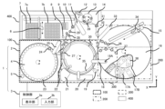
- FIG. 1 is a diagram showing an overview of the overall configuration of an automatic analyzer.
- FIG. 2 is a diagram showing an overview of the automatic analyzer as viewed diagonally from above. A diagram showing an overview of the lower structure of the automatic analyzer.
- FIGS. 1 to 5 An embodiment of the automatic analyzer of the present invention will be described using FIGS. 1 to 5.
- FIG. 1 is a diagram showing an example of a configuration diagram of an automatic analyzer.
- FIG. 2 is a diagram showing an overview of the first analysis and measurement section and the second analysis and measurement section, and
- FIG. 3 is a diagram showing an overview of the first mechanism, the first analysis and measurement section, the second mechanism, and the second analysis and measurement section.
- 4 is a diagram showing an overview of the automatic analyzer as viewed diagonally from above.
- the first mechanism commonly used for the first analysis item group 300 and the second analysis item group 400 is the specimen holding section 4 located in the specimen holding area 100
- the second mechanism commonly used in the second analysis item group 400 is the reagent holding section 16 located in the reagent holding area 200.
- An automatic analyzer 1 shown in FIGS. 1 to 4 is an apparatus for analyzing a sample using a reagent according to a predetermined analysis item, and is composed of an analysis section 2 and a control section 3.
- the analysis section 2 includes a sample holding section 4, a sample information reading section 5, a sample dispensing mechanism 25, a washing tank 26 for the sample dispensing mechanism, a reagent holding section 16, and a first reagent portion.
- the specimen holding unit 4 has a structure capable of holding a plurality of annular specimen containers 23 that contain specimens to be analyzed in the analysis related to the first analysis item group 300 and the analysis related to the second analysis item group 400.
- a sample information reading section 5 is provided around the sample holding section 4 to read information such as a bar code (various information regarding the sample) attached to the sample container.
- the sample information reading section 5 is located at the side edge of the device housing.
- the sample holding section 4 rotates and transports the sample container 23 to the access position of the sample dispensing mechanism 25.
- the sample holding unit 4 includes a sample suction position 24, and immediately before the sample dispensing mechanism 25 aspirates the sample to be analyzed, the sample holding unit 4 rotates and transports the sample container 23 to the sample suction position 24. do.
- the sample holding section 4 partially protrudes from the main frame of the automatic analyzer 1, but it is assumed that it is covered by the cover. It is desirable to do so.
- the specimen holding section 4 may be configured so that the two specimen holding sections 4 can be physically replaced alternately. Samples can also be added or replaced midway through a small window provided in the sample holding section 4. However, it does not have to be constructed by the user himself, and may be transported using a transport mechanism or the like. Further, the sample holding section 4 may have a structure capable of holding a plurality of sample racks capable of holding one or more sample containers 23. Furthermore, the automatic analyzer 1 may be connected to an external sample rack transport mechanism, and the sample racks may be transported to the sample holding section 4.
- the sample dispensing mechanism 25 transfers the sample from the sample container 23 at the sample suction position 24 to the first incubator 35 located at the first analysis sample discharge section 27 of the first analysis and measurement section 301 and from the sample container 23 at the sample suction position 24 to the first incubator 35 located at the first analysis sample discharge section 27 of the first analysis and measurement section 301 .
- It is composed of a rotational drive mechanism, a vertical drive mechanism, and a dispensing probe so as to move above the disposable container 7 located in the analysis sample discharge section 28 and perform sample dispensing.
- the rotational drive mechanism and vertical drive mechanism of the sample dispensing mechanism 25 move between the sample suction position and the sample discharge position, and dispense the sample at the sample suction position 24 into the first incubator 35 or the disposable container 7.
- the aspirated specimen is discharged into the container. After the sample is discharged, it is cleaned in the sample dispensing mechanism cleaning tank 26, and the next sample dispensing operation begins.
- the configuration may be such that each position is accessed by a rotational movement, or the configuration may be such that each position is accessed by a linear movement.
- the reagent holding unit 16 includes a first reagent container containing reagents used for analysis related to the first analysis item group 300 to be reacted in the first incubator 35 and a second analysis item group 400 to be reacted in the disposable container 7. It is a mechanism for holding a plurality of second reagent containers containing reagents used for analysis related to analysis, and includes a reagent disk (omitted for convenience of illustration), reagent container holding positions (first reagent container mounting section 38, It has a second reagent container mounting section 17A, a third reagent container mounting section 17B), and a cover 16A.
- the reagent holding section 16 has a reagent cooling function.
- Reagent container holding positions are arranged in a double ring on the reagent disk, and are configured to hold a plurality of first reagent containers and second reagent containers. The details will be described later. Further, the reagent disk has a rotational drive mechanism, and moves each of the first and second reagent containers to a predetermined position on the circumference by rotational movement.
- the reagent disk rotates before reagent dispensing, and by conveying an appropriate reagent container to the first reagent suction position 37 or the second reagent suction position 36, the first reagent dispensing mechanism 18 or the A two-reagent dispensing mechanism 33 can aspirate reagents necessary for analysis.
- the first reagent container and the second reagent container may each be composed of a plurality of different reagent bottles.
- the automatic analyzer 1 serves as a second dispensing section for dispensing reagents from the reagent holding section 16 to the first analysis and measurement section 301 and the second analysis and measurement section 401, and is for the first analysis item group 300.
- a second reagent dispensing mechanism 33 for discharging into the disposable container 7 is separately provided.
- each of the first reagent dispensing mechanism 18 and the second reagent dispensing mechanism 33 is common, and is composed of a rotational drive mechanism, a vertical drive mechanism, and a dispensing probe.
- the second reagent dispensing mechanism 33 may be configured to be able to aspirate the reagent from the second reagent container while the first reagent dispensing mechanism 18 is aspirating the reagent from the first reagent container. Thereby, it is possible to improve the analysis throughput.
- the first reagent dispensing mechanism 18 and the second reagent dispensing mechanism 33 rotate and descend to the position of a predetermined type of first reagent container or second reagent container in the reagent holding section 16 to aspirate a predetermined amount of reagent. do. After suctioning the reagent, the first reagent dispensing mechanism 18 and the second reagent dispensing mechanism 33 rise.
- the reagent discharge destination for example, the predetermined first incubator 35 in the case of the first reagent dispensing mechanism 18 for biochemical analysis, and the second reagent dispensing position in the case of the second reagent dispensing mechanism 33 for immunological analysis. It rotates and descends into a disposable container 7 for analysis of immune items installed at 31, and discharges each reagent. After the reagent is discharged, it is cleaned in the first reagent dispensing mechanism cleaning tank 19 or the second reagent dispensing mechanism cleaning tank 32, and the next reagent dispensing operation begins.
- a reagent stirring mechanism 34 (also referred to as a stirrer) is set around the reagent holding part 16 as a stirring means for stirring the reagent contained in the second reagent container.
- the reagent stirring mechanism 34 moves to the upper region of the second reagent container containing the magnetic particle solution to be stirred, lowers the magnetic particle stirring element of the reagent stirring mechanism 34, and rotates the stirring element to generate the magnetic particles. Stir the solution.
- the reagent stirring mechanism 34 stirs the magnetic particles immediately before the reagent is dispensed. After stirring, the reagent stirring mechanism is cleaned in a cleaning tank 15.
- the first reaction container transport mechanism 6 has a drive mechanism in the X-axis, Y-axis, and Z-axis directions, and a reaction container gripping mechanism, and has a first tray 7a, a second tray 7b, a reaction container disposal position 8, and a reaction container holding mechanism. 2 incubator 9 and above the second analysis sample discharge section 28.
- the second reaction container transport mechanism 11 has a rotational drive mechanism, a vertical drive mechanism, and a reaction container gripping mechanism, and is a disposable container that accommodates a reaction solution containing a mixture of a sample and a reagent in the analysis related to the second analysis item group 400.
- the container 7 is moved to a stirring position by the second stirring mechanism 10 provided on a rotating orbit, the second analysis sample discharge part 28, the reaction container standby position 29, the second detection part preparation operation mechanism 13, the second reagent discharge position 31, etc. It has a function to move to each reaction container installation position.
- the first reaction container transport mechanism 6 transports one disposable container 7 from the first tray 7 a and the second tray 7 b that accommodate unused disposable containers 7 to the second analytical sample discharge section 28 .
- the sample dispensing mechanism 25 dispenses a predetermined amount of sample into the disposable container 7 installed in the second analysis sample discharge section 28. Thereafter, the disposable container 7 into which the specimen has been discharged is transported to the second reagent discharge position 31 by the reaction container second transport mechanism 11 .
- the second reagent dispensing mechanism 33 dispenses a predetermined amount of R1/R2 reagent into the disposable container 7 installed at the second reagent discharge position 31. Thereafter, the disposable container 7 is moved to the position of the second stirring mechanism 10 by the reaction container second transport mechanism 11, and the liquid mixture in the disposable container 7 is stirred.
- the disposable container 7 After stirring the reaction solution, the disposable container 7 is moved to the second incubator 9 by the reaction container first transport mechanism 6. Here, if dilution is necessary, the disposable container 7 is transported to the dilution position 28a, and the diluted sample is aspirated in the next cycle.
- the disposable container 7 is transported to the reaction container standby position 29 by the reaction container first transport mechanism 6, and when the next reagent dispensing timing comes, the second reaction container transport mechanism 11 transports the disposable container 7 to the reaction container standby position 29. Transport to position 31.
- the Beads reagent is dispensed into the disposable container 7 by the second reagent dispensing mechanism 33, and then the disposable container 7 is transported to the second stirring mechanism 10 by the reaction container second transport mechanism 11 for further stirring. conduct.
- the disposable container 7 is transported to the second incubator 9 by the reaction container first transport mechanism 6.
- the second incubator 9 is temperature-controlled to an appropriate temperature for the purpose of holding the disposable container 7 and promoting the reaction between the specimen and the reagent, and when the reaction process between the specimen and the reagent on the second incubator 9 is completed, the reaction
- the first container transport mechanism 6 transports the disposable container 7 to the reaction container standby position 29 .
- the reaction liquid cleaning displacement mechanism 12 and the second detection section preparation operation mechanism 13 are moved, and the pre-cleaning step is carried out. implement.
- the disposable container 7 is transported to the second stirring mechanism 10 by the second reaction container transport mechanism 11 . Thereafter, the disposable container 7 is transported by the reaction container first transport mechanism 6 to the mixed liquid suction position on the second detection section preparation operation mechanism 13, and the second detection section preparation operation mechanism 13 is moved below the second analysis detection section 14. Move to the reaction liquid suction position provided in , and aspirate the reaction liquid. Thereafter, the reaction solution is sucked into the detection section in the second analysis detection section 14, and the reaction signal is measured.
- the second reaction container transport mechanism 11 transports the disposable container 7 to the reaction container standby position 29, and the first reaction container transport mechanism 6 transports it to the reaction container disposal position 8 for disposal.
- the automatic analyzer 1 of this embodiment has a first analysis sample discharge section 27 in which the first incubator 35 that receives the sample from the sample dispensing mechanism 25 is placed, a second analysis sample discharge section 28 on which a disposable container 7 is placed to receive the reagent dispensed; a second reagent discharge position 31 on which the disposable container 7 is placed to receive the reagent dispensed from the second dispensing section; A reaction container second transport mechanism 11 is provided that transports the disposable container 7 between the second analysis sample discharge section 28, the second analysis measurement section 401, and the second reagent discharge position 31.
- the suction position of the sample dispensing mechanism 25, the first analysis sample discharging section 27, and a second analysis sample discharge section 28 are arranged.
- the first incubator 35 is a mechanism that holds a reaction solution for analysis by the first analysis detection unit 21 that measures the reaction solution in the analysis related to the first analysis item group 300, and like the second incubator 9, it contains specimens and reagents.
- the temperature is controlled at an appropriate temperature to promote the reaction with
- the sample dispensing mechanism 25 dispenses a predetermined amount of a sample into a predetermined first incubator 35 that accommodates a reaction solution containing a mixture of a sample and a reagent in an analysis related to the first analysis item group 300. Thereafter, the first incubator 35 is rotated, and the first incubator 35 from which the specimen has been discharged is moved to the access position of the first reagent dispensing mechanism 18, and the first reagent dispensing mechanism 18 is connected to the first incubator from which the specimen has been discharged. Dispense a predetermined amount of reagent into 35 tubes.
- the first incubator 35 rotates, and the first incubator 35 from which the specimen and reagent have been discharged is moved to the first stirring mechanism 30 installation position, and the specimen and reagent in the first incubator 35 are stirred by the first stirring mechanism 30. be done.
- the first incubator 35 rotates, and the first incubator 35 containing the reaction solution after the reaction is completed is used for a first analysis for analyzing biochemical items of the sample. It is moved to the installation position of the detection unit 21.
- the detection section in the first analysis detection section 21 measures the reaction signal. After the signal measurement, the reaction solution is discharged from the first incubator 35 by the reaction container cleaning mechanism 22.
- electrolyte items may be further installed as the measurement unit 20 that can accompany the biochemical items.
- analysis items that can be added are not limited to electrolyte items, and may be other analysis items.
- the mechanism described above in the automatic analyzer 1 is referred to as the analysis operation section.
- the automatic analyzer 1 includes a control section 3 that controls the operation of each device in the automatic analyzer 1, including the sample holding section 4 and the sample dispensing mechanism 25.
- the control unit 3 may be composed of a computer having a display unit 3a such as a liquid crystal display, an input unit 3b, a storage device, a CPU, a memory, etc., and may be composed of one computer or another computer. It may be configured by a computer, and is not particularly limited.
- the control section 3 at least the display section 3a and the input section 3b are preferably arranged on the side where the specimen holding section 4 is arranged, especially when the specimen is It is desirable to arrange it between the holding part 4 and the second analysis part 400.
- the input unit 3b be movable to a position where the user can easily access it when in use, and to a position that does not obstruct the user's access to various mechanisms around the specimen holding unit 4 when not in use.
- Control of the operation of each device by the control unit 3 is executed based on various programs recorded in the storage device. Note that the control processing of the operations executed by the control unit 3 may be summarized into one program, each may be divided into a plurality of programs, or a combination thereof may be used. Further, part or all of the program may be realized by dedicated hardware or may be modularized.
- a mechanism that can be used in common for the analysis related to the first analysis item group 300 and the analysis related to the second analysis item group 400 (in this example, the sample holding part 4 , the reagent holding section 16, and the sample dispensing mechanism 25), thereby eliminating the need for a dedicated mechanism.
- the mechanical layout maintains the characteristics of the main mechanical layout for each item.
- the layout of the main mechanism of the first analysis item group 300 continuously monitors the reaction process from discharging the sample and reagent to extracting the measurement result, and removes the liquid in the first incubator 35 after measurement.
- the main mechanisms are arranged on the circumference of the first incubator 35, and other main mechanisms are laid out on the circumference of the first incubator 35.
- the main mechanism layout of the second analysis item group 400 is a test method that uses disposable containers 7 for each test item from the viewpoint of preventing contamination between samples.
- the main mechanism is laid out in such a way that the disposable containers 7 can be handled between areas for each functional use such as reagent reaction, reaction liquid measurement, etc.
- the horizontal direction of the assumed user's standing position (Figs. 1 to 3, lower middle side of Fig. 5) as the X-axis
- the direction perpendicular to this X-axis as the Y-axis.
- the sample holding section 4 the first analysis and measurement section 301, and the reagent holding section 16 were arranged in this order.
- the sample input and sample storage area into the automatic analyzer 1 and the reagent input and reagent storage area were placed on the left and right sides of the front side of the apparatus, respectively, for easy access. .
- the first analysis and measurement section 301 and the second analysis and measurement section 401 were arranged in this order along the Y axis in the direction away from the standing position (upper side in FIGS. 1 to 3 and 5).
- the first analysis and measurement section 301 since the first analysis and measurement section 301 has a structure in which the reaction process and various treatments are continuously carried out in the first incubator 35, there are relatively many short units, whereas the second analysis and measurement section 301 Since the section 401 has a structure for delivering the disposable container 7, there are many units, and many of the units and structures are tall overall. Therefore, from the viewpoint of usability, in order to ensure accessibility and visibility, the first analysis and measurement section 301 was laid out on the front side of the central part of the automatic analyzer 1, and the second analysis and measurement section 401 was laid out on the back side.
- the second analysis and measurement section 401 was installed higher than the first analysis and measurement section 301 in the vertical direction. More specifically, the first analysis and measurement section 301 was installed at the same height as the apparatus table surface, whereas the second analysis and measurement section 401 was installed at a higher position from the table surface in the vertical direction.
- a touch panel 3c serving as the display section 3a and input section 3b of the control section 3 was placed between the sample holding section 4 and the second analysis section 400.
- FIG. 5 is a diagram showing an outline of the lower structure of the automatic analyzer.
- the apparatus standing position 44 of the automatic analyzer 1 of the present invention can be located inside the apparatus, compared to the conventional apparatus standing position 43.
- the first reagent container containing the first reagent for the first analysis item group 300 and the second analysis item group 400 is different analysis items. It is desirable that the shape of the second reagent container containing the second reagent for group 400 is different. In this case, it is desirable that the reagent holding section 16 be provided with a dedicated position for holding each reagent container.
- the reagent holding section 16 has a first reagent container mounting section 38 that can hold only the first reagent container containing the first reagent among the reagents as the second liquid, and a first reagent holding section 38 as a reagent holding position.
- a second reagent container mounting portion 17A that can hold only a second reagent container containing a second reagent different in type from the first reagent, and a third reagent that can hold both the first reagent container and the second reagent container. It has a container mounting part 17B.
- Each position of the first reagent container placement portion 38, the second reagent container placement portion 17A, and the third reagent container placement portion 17B is such that only the first reagent container placement portion 38 is located on the inner circumferential side.
- the second reagent container placement portion 17A and the third reagent container placement portion 17B are arranged in a double ring shape alternately on the outer circumferential side.
- first reagent container placement portion 38 on the inner circumference side and the third reagent container placement portion 17B on the outer circumference side are configured such that the longitudinal direction thereof is such that the first reagent dispensing mechanism 18 can easily access the reagent container. It is assumed that the position is not parallel to a line extending radially from the center of the holding part 16.
- the second reagent container placement section 17A is positioned such that its longitudinal direction is not parallel to the longitudinal directions of the first reagent container placement section 38 and the third reagent container placement section 17B. did.
- the operating areas of the first reagent dispensing mechanism 18 and the second reagent dispensing mechanism 33 should interfere with each other. It is desirable not to do so. Also, the distance between the reagent suction position and the reagent discharge position (between the first reagent suction position 37 and the reagent discharge position of the first incubator 35, between the second reagent suction position 36 and the second reagent discharge position 31), (distance) is desirable.
- the rotating shaft 18A of the arm thereof is arranged on the cover 16A of the reagent holding section 16.
- the first reagent container and the second reagent container are provided with a stopper to prevent deterioration of the reagent. Further, the second reagent container containing the second liquid for the second analysis item group 400 may be provided with a cap instead of a stopper.
- the automatic analyzer 1 is equipped with a needle that automatically opens the caps for reagent containers inserted into the device. It is provided in the first reagent dispensing mechanism cleaning tank 19 in a form that is detachable from the dispensing mechanism 18 . Similarly, an opener 46 is provided near the second reagent aspiration position 36 as a mechanism for removing the cap.
- the cleaning tank 19 for the first reagent dispensing mechanism is not located between the first reagent suction position 37 and the reagent discharge position of the first incubator 35, but between the first reagent suction position 37 of the first reagent dispensing mechanism 18 and the reagent discharge position of the first incubator 35. It is arranged around the first incubator 35 on the extension line of the operation locus with the reagent discharge position of the first incubator 35, after the input of the reagent container is recognized, and at a timing that does not overlap with the timing of reagent suction, etc. The first reagent dispensing mechanism 18 grips the needle, opens the cap, and cleans the needle.
- the reagent stirring mechanism 34 is provided, but in order to shorten the operating distance of the reagent stirring mechanism 34 as much as possible, it must be placed at a position that does not overlap with the operating area of the second reagent dispensing mechanism 33 and at the outer periphery of the reagent holder 16. It is desirable to extend from the side to the second reagent suction position 36, which is the stirring position, at the shortest distance. However, in that case, it will be difficult to access the reagent stirring mechanism 34 from the front side of the automatic analyzer 1, and it is expected that maintenance will be troublesome.
- the reagent holding section 16 is provided at a position on the outer periphery on the opposite side to the side where the second reagent suction position 36 is located so as to be on the front side of the automatic analyzer 1. It is assumed that the trajectory straddles most of the reagent holding section 16.
- the operation will take time, but since the operation locus of the reagent stirring mechanism 34 does not overlap with the operation area of the second reagent dispensing mechanism 33, if stirring is necessary, it is necessary to This can be dealt with by moving near the second reagent suction position 36 and waiting at a timing up to this point, and there is almost no problem on the time chart.
- the second analysis sample dispensing unit 28 is used after aspirating the sample. Before moving, it is necessary to pass over the first incubator 35 in addition to the first analysis sample discharge section 27. At this time, in order to prevent the sample from dripping onto the first incubator 35, at least the first analysis sample discharge section 27 and the first analysis sample discharge section 27 are It is desirable that a cover be provided above the area between the two analytical sample discharge sections 28.
- the second analysis sample discharging unit 28 Although it is possible to access the second analysis sample discharging unit 28 without passing over the first incubator 35, the operating distance becomes longer, and the first tray 7a and the second tray 7b Although it is necessary to pass over the top of the first tray 7a and the second tray 7b, similar measures such as covering the first tray 7a and the second tray 7b must be taken, so in order to shorten the travel distance, the second analysis It is desirable that the trajectory of movement to the sample discharge section 28 passes over the first incubator 35 .
- the automatic analyzer 1 of the present embodiment described above includes the sample dispensing mechanism 25 that dispenses the first liquid from the first mechanism to the first analysis and measurement section 301 and the second analysis and measurement section 401, and the sample dispensing mechanism 25 that dispenses the first liquid from the first mechanism to the first analysis and measurement section 301 and the second analysis and measurement section 401.
- a second dispensing section that dispenses a second liquid different from the first liquid to the analysis and measurement section 301 and the second analysis and measurement section 401, or the first analysis and measurement that performs analysis related to a group of biochemical items.
- the X-axis represents the left and right direction of the assumed user's standing position
- the Y-axis represents the direction perpendicular to the X-axis.
- the first mechanism, the first analysis and measurement section 301, and the second mechanism are arranged in this order from the left of the standing position, and the first mechanism is arranged in the direction away from the standing position along the Y-axis. It is assumed that the first analysis measurement section 301 and the second analysis measurement section 401 are arranged in this order.
- an automatic analyzer that can perform analysis of two analysis items with different operating methods and measurement principles has a mechanical layout and system configuration specialized for each operation, and it also has an improved operability compared to conventional instruments. It is possible to appropriately arrange or simplify the mechanical layout according to each item while inheriting the above. Furthermore, it is possible to prevent the installation area of the automatic analyzer 1 from becoming larger than necessary.
- the sample dispensing mechanism 25 is configured to dispense the sample to the first analysis and measurement section 301 and the second analysis and measurement section 401.
- the second dispensing section includes the first reagent dispensing mechanism 18 configured to dispense the reagent for the first analysis item group 300 to the first analysis and measurement section 301 and the second analysis and measurement section 401.
- the second reagent dispensing mechanism 33 configured to dispense reagents for the second analysis item group 400
- the second analysis section that dispenses access to each analysis section can be paired with the analysis section.
- the method can be configured with a special dispensing probe, which prevents mistakes in reagent dispensing and decreases in analysis throughput.
- the second analysis and measurement section 401 vertically higher than the first analysis and measurement section 301, the structure corresponding to each measurement principle is maintained, and the When accessing the second analysis and measurement section 401 provided on the side, it is possible to prevent the first analysis and measurement section 301 from becoming an obstacle and to facilitate access.
- a space into which the user's toes can be inserted is provided vertically below at least one of the first mechanism, the first analysis and measurement unit 301, and the second mechanism and on a surface that contacts the floor in a standing position. This makes it easier to access the back side of the automatic analyzer 1.
- a first analysis sample discharge section 27 in which a first incubator 35 for receiving the sample to be dispensed from the sample dispensing mechanism 25 is placed, and a disposable container 7 for receiving the sample to be dispensed from the sample dispensing mechanism 25 are placed therein.
- the automatic analyzer 1 is equipped with a reaction container second transport mechanism 11 that transports the reaction container between the discharge section 28, the second analysis measurement section 401, and the second reagent discharge position 31, and when the automatic analyzer 1 is viewed from above in the vertical direction, By arranging the suction position of the sample dispensing mechanism 25, the first analytical sample discharging section 27, and the second analytical sample discharging section 28 at a position that overlaps with the movement trajectory of the dispensing probe of the sample dispensing mechanism 25, The handling of the disposable container 7 in the second analysis measurement unit 401 can be performed efficiently.
- first reagent container placement section 38 and the third reagent container placement section 17B are arranged parallel to a line extending radially from the center of the reagent holding section 16 so that the first reagent dispensing mechanism 18 can be easily accessed.
- the user can freely set the distribution of the various reagent containers stored in the third reagent container placement section 17B, allowing flexibility within the limited number of storage containers. This can lead to improved usability.
- the first reagent dispensing mechanism 18 dispenses the first reagent from the first reagent containers mounted on the first reagent container mounting section 38 and the third reagent container mounting section 17B, and the second reagent dispensing. It is possible to easily achieve both dispensing of the second reagent by the mechanism 33 from the second reagent container mounted on the second reagent container mounting portion 17A.
- the first reagent dispensing mechanism 18 is arranged so that the rotating shaft 18A of the arm is disposed on the cover 16A of the reagent holding section 16, so that the first reagent dispensing mechanism 18 can be mounted on the first reagent container mounting section 38 and the third reagent container mounting section 38.
- the arrangement can achieve both a reduction in the mounting area of the device while dispensing the first reagent from the first reagent container mounted on the storage section 17B.
- Second stirring mechanism 11 Reaction container second transport mechanism (transport unit) 12: Reaction liquid cleaning displacement mechanism 13: Second detection unit preparation mechanism 14: Second analysis detection unit 15: Reagent stirring mechanism cleaning tank 16: Reagent holding unit (second mechanism) 16A: Cover 17A: Second reagent container placement part (second placement part) 17B: Third reagent container placement part (third placement part) 18: First reagent dispensing mechanism (second dispensing section, first arm) 18A: Rotation shaft 19: First reagent dispensing mechanism cleaning tank 20: Measuring section 21 that can be attached to the first analysis item: First analysis detection section 22: Reaction container cleaning mechanism 23: Sample container 24: Sample suction position 25
Abstract
When provided with a specimen dispensing mechanism 25 that dispenses a first liquid from a first mechanism into the first analyzing and measuring unit 301 and a second analyzing and measuring unit 401, and a second dispensing unit that dispenses a second liquid different from the first liquid from a second mechanism into the first analyzing and measuring unit 301 and a second analyzing and measuring unit 401, or when provided with a first analyzing and measuring unit 301 for analyses pertaining to biochemical item groups and a second analyzing and measuring unit 401 for analyses pertaining to immunization item groups, the automated analyzer of the present invention has, where the x-axis is defined as the left/right direction from the user's standing position and the y-axis is defined as the direction perpendicular to the x-axis, the first mechanism, the first analyzing and measuring unit 301, and the second mechanism arranged in order along the X-axis from the left of the standing position, and the first analyzing and measuring unit 301 and the second analyzing and measuring unit 401 arranged in this order along the Y-axis in the direction away from the standing position. Thereby provided is an automatic analyzer that realizes a mechanism layout in line with each item while maintaining the operational feel of a conventional device.
Description
本発明は、自動分析装置に関する。
The present invention relates to an automatic analyzer.
特許文献1には、それぞれが異なる種類の分析を行う少なくとも2つ以上の異なる測定ユニットを複合的に1台の装置構成で構築した自動分析装置について記載されている。
Patent Document 1 describes an automatic analyzer in which at least two or more different measurement units, each of which performs a different type of analysis, are constructed into a single device configuration.
上述の特許文献1の装置構成の場合、各項目測定に特化した装置構成及び検体投入部を組み合わせるシステム構成となっている。このため、使用できるのが検査室内の敷地面積における自動分析装置の占有面積を広く使用可能な大規模/中規模の検査室に限定されてしまう、との課題がある。
In the case of the device configuration of Patent Document 1 mentioned above, the system configuration is a combination of a device configuration specialized for each item measurement and a sample input section. For this reason, there is a problem in that it can be used only in large-scale/medium-sized laboratories where the area occupied by the automatic analyzer in the site area of the laboratory can be widely used.
このため、小規模の検査室をターゲットとしている複数の項目分析を実施する統合型の自動分析装置では、その占有面積をより縮小することが望ましい。
For this reason, it is desirable to further reduce the area occupied by an integrated automatic analyzer that performs multiple item analysis and is targeted at small-scale laboratories.
ここで、従来製品とのファミリ製品であれば、オペレータの負担の軽減などの観点から、従来装置の操作感や分析原理、動作手法は同等もしくは類似していることが望ましい。しかし、各項目で動作手法や測定原理が異なるため、機構レイアウトやシステム構成は各動作に特化していることがほとんどである。このため、従来装置の操作感を継承しつつ、各々の項目に沿った機構レイアウトを適切に配置、又は簡略化する必要がある。
Here, if the product is a family product with a conventional product, it is desirable that the operating feel, analysis principles, and operating methods of the conventional device be the same or similar, from the perspective of reducing the burden on the operator. However, since the operating methods and measurement principles differ for each item, the mechanical layout and system configuration are mostly specialized for each operation. Therefore, it is necessary to appropriately arrange or simplify the mechanical layout according to each item while inheriting the operational feel of the conventional device.
本発明は、従来装置の操作感を継承しつつ、各々の項目に沿った機構レイアウトを実現した自動分析装置を提供する。
The present invention provides an automatic analysis device that inherits the operational feel of the conventional device and realizes a mechanical layout according to each item.
本発明は、上記課題を解決する手段を複数含んでいるが、その一例を挙げるならば、第1分析項目群に係る分析を行う第1分析部と、前記第1分析項目群とは異なる第2分析項目群に係る分析を行う第2分析部と、前記第1分析項目群及び前記第2分析項目群に共通して使用される第1機構と、前記第1機構とは異なる機構であり、前記第1分析項目群及び前記第2分析項目群に共通して使用される第2機構と、前記第1機構から前記第1分析部及び前記第2分析部へ第1液体を分注する第1分注部と、前記第2機構から前記第1分析部及び前記第2分析部へ第1液体とは異なる第2液体を分注する第2分注部と、を備え、想定されるユーザの立ち位置の左右方向をX軸、前記X軸に対して垂直の方向をY軸と定義した場合において、前記X軸に沿って、前記立ち位置の左から前記第1機構、前記第1分析部、前記第2機構の順に配置され、前記立ち位置から遠ざかる方向に、前記Y軸に沿って、前記第1分析部、前記第2分析部の順に配置されることを特徴とする。
The present invention includes a plurality of means for solving the above problems, and to give one example, a first analysis section that performs an analysis related to a first analysis item group, and a first analysis section that performs an analysis related to a first analysis item group; A second analysis unit that performs analysis related to two analysis item groups, a first mechanism that is commonly used for the first analysis item group and the second analysis item group, and a mechanism that is different from the first mechanism; , a second mechanism commonly used for the first analysis item group and the second analysis item group, and dispensing a first liquid from the first mechanism to the first analysis section and the second analysis section. a first dispensing section; a second dispensing section that dispenses a second liquid different from the first liquid from the second mechanism to the first analysis section and the second analysis section; In a case where the left-right direction of the user's standing position is defined as the X-axis, and the direction perpendicular to the X-axis is defined as the Y-axis, along the X-axis, from the left of the standing position, the first mechanism, the first The analysis unit and the second mechanism are arranged in this order, and the first analysis unit and the second analysis unit are arranged in this order along the Y-axis in the direction away from the standing position.
また、他の一例をあげるならば、生化学項目群に係る分析を行う第1分析部と、免疫項目群に係る分析を行う第2分析部と、前記生化学項目群及び前記免疫項目群に共通して使用される第1機構と、前記第1機構とは異なる機構であり、前記生化学項目群及び前記免疫項目群に共通して使用される第2機構と、を備え、想定されるユーザの立ち位置の左右方向をX軸、前記X軸に対して垂直の方向をY軸と定義した場合において、前記X軸に沿って、前記立ち位置の左から前記第1機構、前記第1分析部、前記第2機構の順に配置され、前記立ち位置から遠ざかる方向に、前記Y軸に沿って、前記第1分析部、前記第2分析部の順に配置されることを特徴とする。
To give another example, a first analysis section that performs an analysis related to a group of biochemical items, a second analysis section that performs an analysis related to a group of immune items, and a second analysis section that performs an analysis related to a group of biochemical items and a group of immunological items, A first mechanism that is commonly used, and a second mechanism that is different from the first mechanism and is commonly used for the biochemical item group and the immunological item group, and is assumed to be In a case where the left-right direction of the user's standing position is defined as the X-axis, and the direction perpendicular to the X-axis is defined as the Y-axis, along the X-axis, from the left of the standing position, the first mechanism, the first The analysis unit and the second mechanism are arranged in this order, and the first analysis unit and the second analysis unit are arranged in this order along the Y-axis in the direction away from the standing position.
本発明によれば、従来装置の操作感を継承しつつ、各々の項目に沿った機構レイアウトを実現できる。上記した以外の課題、構成及び効果は、以下の実施例の説明により明らかにされる。
According to the present invention, it is possible to realize a mechanical layout in line with each item while inheriting the operational feel of the conventional device. Problems, configurations, and effects other than those described above will be made clear by the description of the following examples.
本発明の自動分析装置の実施例について図1乃至図5を用いて説明する。
An embodiment of the automatic analyzer of the present invention will be described using FIGS. 1 to 5.
なお、以下に説明する実施例は一例であり、要旨を逸脱しない範囲で変形実施することが可能である。また、1つの例示的な態様と共に図示又は記述される特色を、他の態様の特色と組み合わせてもよい。
Note that the embodiments described below are merely examples, and modifications can be made without departing from the scope of the invention. Additionally, features illustrated or described with one exemplary embodiment may be combined with features of other embodiments.
また、本明細書で用いる図面において、同一の又は対応する構成要素には同一、又は類似の符号を付け、これらの構成要素については繰り返しの説明を省略する場合がある。
In addition, in the drawings used in this specification, the same or corresponding components are given the same or similar symbols, and repeated description of these components may be omitted.
最初に、自動分析装置の全体構成について図1乃至図4を用いて説明する。図1は、自動分析装置の構成図の一例を示す図である。図2は第1分析測定部及び第2分析測定部の概要を示す図、図3は第1機構、第1分析測定部、第2機構、及び第2分析測定部の概要を示す図、図4は自動分析装置を斜め上方から見たときの概要を示す図である。
First, the overall configuration of the automatic analyzer will be explained using FIGS. 1 to 4. FIG. 1 is a diagram showing an example of a configuration diagram of an automatic analyzer. FIG. 2 is a diagram showing an overview of the first analysis and measurement section and the second analysis and measurement section, and FIG. 3 is a diagram showing an overview of the first mechanism, the first analysis and measurement section, the second mechanism, and the second analysis and measurement section. 4 is a diagram showing an overview of the automatic analyzer as viewed diagonally from above.
自動分析装置1では、第1分析項目群300及び第2分析項目群400に共通して使用される第1機構は検体保持領域100に位置する検体保持部4であり、第1分析項目群300及び第2分析項目群400に共通して使用される第2機構は試薬保持領域200に位置する試薬保持部16とする。また、第1分析項目群300は生化学に係る項目群を示し、第2分析項目群400は免疫に係る項目群を示す場合について説明するが、この組み合わせに限定されないことは言うまでもない。
In the automatic analyzer 1, the first mechanism commonly used for the first analysis item group 300 and the second analysis item group 400 is the specimen holding section 4 located in the specimen holding area 100, The second mechanism commonly used in the second analysis item group 400 is the reagent holding section 16 located in the reagent holding area 200. Furthermore, although a case will be described in which the first analysis item group 300 represents a biochemistry-related item group and the second analysis item group 400 represents an immunity-related item group, it goes without saying that the combination is not limited to this.
図1乃至図4に示す自動分析装置1は、検体を所定の分析項目に応じた試薬を用いて分析するための装置であり、分析部2と制御部3とから構成される。
An automatic analyzer 1 shown in FIGS. 1 to 4 is an apparatus for analyzing a sample using a reagent according to a predetermined analysis item, and is composed of an analysis section 2 and a control section 3.
分析部2は、図1乃至図4に示すように、検体保持部4、検体情報読取部5、検体分注機構25、検体分注機構用洗浄槽26、試薬保持部16、第1試薬分注機構18、第1試薬分注機構用洗浄槽19、第2試薬分注機構33、オープナー46、第2試薬分注機構用洗浄槽32、試薬撹拌機構34、試薬撹拌機構用洗浄槽15、第2分析検出部14、第1インキュベータ35、第1撹拌機構30、第1分析検出部21、反応容器洗浄機構22、反応容器第1搬送機構6、第2インキュベータ9、第2撹拌機構10、反応容器第2搬送機構11等を備えている。
As shown in FIGS. 1 to 4, the analysis section 2 includes a sample holding section 4, a sample information reading section 5, a sample dispensing mechanism 25, a washing tank 26 for the sample dispensing mechanism, a reagent holding section 16, and a first reagent portion. Note mechanism 18, first reagent dispensing mechanism cleaning tank 19, second reagent dispensing mechanism 33, opener 46, second reagent dispensing mechanism cleaning tank 32, reagent stirring mechanism 34, reagent stirring mechanism cleaning tank 15, second analysis detection section 14, first incubator 35, first stirring mechanism 30, first analysis detection section 21, reaction container cleaning mechanism 22, reaction container first transport mechanism 6, second incubator 9, second stirring mechanism 10, It is equipped with a reaction container second transport mechanism 11 and the like.
検体保持部4は、第1分析項目群300に係る分析及び第2分析項目群400に係る分析において分析対象となる検体を収容する検体容器23を環状に複数保持可能な構造となっている。この検体保持部4の周囲には、検体容器に取り付けられたバーコード等の情報(検体に関する様々な情報)を読み取るための検体情報読取部5が設けられる。好適には、検体情報読取部5は、装置筐体の側面端部に位置することが望ましい。
The specimen holding unit 4 has a structure capable of holding a plurality of annular specimen containers 23 that contain specimens to be analyzed in the analysis related to the first analysis item group 300 and the analysis related to the second analysis item group 400. A sample information reading section 5 is provided around the sample holding section 4 to read information such as a bar code (various information regarding the sample) attached to the sample container. Preferably, the sample information reading section 5 is located at the side edge of the device housing.
検体分注の際に検体保持部4が回転し、検体分注機構25のアクセスポジションへ検体容器23を輸送する。この検体保持部4は検体吸引位置24を備えており、検体分注機構25が分析対象の検体を吸引する直前に、検体保持部4が回転し、検体容器23を検体吸引位置24へと搬送する。
During sample dispensing, the sample holding section 4 rotates and transports the sample container 23 to the access position of the sample dispensing mechanism 25. The sample holding unit 4 includes a sample suction position 24, and immediately before the sample dispensing mechanism 25 aspirates the sample to be analyzed, the sample holding unit 4 rotates and transports the sample container 23 to the sample suction position 24. do.
ここで、検体保持部4は、自動分析装置1の筐体をできる限り小さくするために、自動分析装置1のメインフレームから一部分はみ出しているものとするが、カバーには覆われているものとすることが望ましい。
Here, in order to make the casing of the automatic analyzer 1 as small as possible, it is assumed that the sample holding section 4 partially protrudes from the main frame of the automatic analyzer 1, but it is assumed that it is covered by the cover. It is desirable to do so.
なお、検体保持部4は物理的に2つの検体保持部4を交互に入れ替えて使用可能に構成されてもよい。検体保持部4に設けられた小窓を介して検体の途中追加・交換などもできる。但し、ユーザが自ら架設する形態である必要は無く、搬送機構などを用いて搬送する形式としてもよい。また、検体保持部4は検体容器23を1つ又は複数保持可能な検体ラックを複数保持可能な構造であってもよい。更に、自動分析装置1が外部の検体ラック搬送機構と接続され、検体保持部4へ検体ラックが搬送される形式としてもよい。
Note that the specimen holding section 4 may be configured so that the two specimen holding sections 4 can be physically replaced alternately. Samples can also be added or replaced midway through a small window provided in the sample holding section 4. However, it does not have to be constructed by the user himself, and may be transported using a transport mechanism or the like. Further, the sample holding section 4 may have a structure capable of holding a plurality of sample racks capable of holding one or more sample containers 23. Furthermore, the automatic analyzer 1 may be connected to an external sample rack transport mechanism, and the sample racks may be transported to the sample holding section 4.
検体分注機構25は、検体吸引位置24にある検体容器23から第1分析測定部301の第1分析検体吐出部27に位置する第1インキュベータ35の上、及び第2分析測定部401の第2分析検体吐出部28に位置するディスポーザブル容器7の上に移動して検体分注を実施するように、回転駆動機構、上下駆動機構、及び分注プローブから構成されている。
The sample dispensing mechanism 25 transfers the sample from the sample container 23 at the sample suction position 24 to the first incubator 35 located at the first analysis sample discharge section 27 of the first analysis and measurement section 301 and from the sample container 23 at the sample suction position 24 to the first incubator 35 located at the first analysis sample discharge section 27 of the first analysis and measurement section 301 . 2. It is composed of a rotational drive mechanism, a vertical drive mechanism, and a dispensing probe so as to move above the disposable container 7 located in the analysis sample discharge section 28 and perform sample dispensing.
この検体分注機構25の回転駆動機構及び上下駆動機構により検体吸引位置と検体吐出位置との間を移動して、検体吸引位置24において検体を分注し、第1インキュベータ35あるいはディスポーザブル容器7に対して吸引した検体を吐出する。検体の吐出後は、検体分注機構用洗浄槽26にて洗浄され、次の検体分注動作に移行する。
The rotational drive mechanism and vertical drive mechanism of the sample dispensing mechanism 25 move between the sample suction position and the sample discharge position, and dispense the sample at the sample suction position 24 into the first incubator 35 or the disposable container 7. The aspirated specimen is discharged into the container. After the sample is discharged, it is cleaned in the sample dispensing mechanism cleaning tank 26, and the next sample dispensing operation begins.
なお、図示されているように、回転動作によって各位置にアクセスする構成であってもよいし、直線動作によって各位置にアクセスする構成であってもよい。
Note that, as shown in the figure, the configuration may be such that each position is accessed by a rotational movement, or the configuration may be such that each position is accessed by a linear movement.
試薬保持部16は、第1インキュベータ35で反応させる、第1分析項目群300に係る分析に使用する試薬が収容された第1試薬容器や、ディスポーザブル容器7で反応させる、第2分析項目群400に係る分析に使用する試薬が収容された第2試薬容器を複数保持するための機構であり、試薬ディスク(図示の都合上省略)、試薬容器保持ポジション(第1試薬容器載置部38、第2試薬容器載置部17A、第3試薬容器載置部17B)及びカバー16Aを有する。試薬保持部16は、試薬の保冷機能を備えている。
The reagent holding unit 16 includes a first reagent container containing reagents used for analysis related to the first analysis item group 300 to be reacted in the first incubator 35 and a second analysis item group 400 to be reacted in the disposable container 7. It is a mechanism for holding a plurality of second reagent containers containing reagents used for analysis related to analysis, and includes a reagent disk (omitted for convenience of illustration), reagent container holding positions (first reagent container mounting section 38, It has a second reagent container mounting section 17A, a third reagent container mounting section 17B), and a cover 16A. The reagent holding section 16 has a reagent cooling function.
試薬ディスク上には試薬容器保持ポジションが二重環状に並んでおり、複数の第1試薬容器や第2試薬容器を保持できるように構成されている。その詳細は後述する。また、試薬ディスクは回転駆動機構を有し、回転運動によって各々の第1試薬容器や第2試薬容器を円周部上の所定位置へ移動させる。
Reagent container holding positions are arranged in a double ring on the reagent disk, and are configured to hold a plurality of first reagent containers and second reagent containers. The details will be described later. Further, the reagent disk has a rotational drive mechanism, and moves each of the first and second reagent containers to a predetermined position on the circumference by rotational movement.
試薬保持部16では、試薬分注前に試薬ディスクが回転し、第1試薬吸引位置37もしくは第2試薬吸引位置36に適切な試薬容器を搬送することで、第1試薬分注機構18もしくは第2試薬分注機構33が分析に必要な試薬を吸引することができる。
In the reagent holding section 16, the reagent disk rotates before reagent dispensing, and by conveying an appropriate reagent container to the first reagent suction position 37 or the second reagent suction position 36, the first reagent dispensing mechanism 18 or the A two-reagent dispensing mechanism 33 can aspirate reagents necessary for analysis.
ここで、第1試薬容器及び第2試薬容器は、それぞれ複数の異なる試薬ボトルから構成されていてもよい。
Here, the first reagent container and the second reagent container may each be composed of a plurality of different reagent bottles.
自動分析装置1は、試薬保持部16から第1分析測定部301及び第2分析測定部401へ試薬を分注する第2分注部として、第1分析項目群300用であり、第1試薬容器から吸引した試薬を第1分析に係る第1インキュベータ35に吐出する第1試薬分注機構18と、第2分析項目群400用であり、第2試薬容器から吸引した試薬を第2分析に係るディスポーザブル容器7に吐出する第2試薬分注機構33と、をそれぞれ個別に備えている。
The automatic analyzer 1 serves as a second dispensing section for dispensing reagents from the reagent holding section 16 to the first analysis and measurement section 301 and the second analysis and measurement section 401, and is for the first analysis item group 300. A first reagent dispensing mechanism 18 for discharging the reagent sucked from the container into the first incubator 35 related to the first analysis, and a second analysis item group 400 for discharging the reagent sucked from the second reagent container for the second analysis. A second reagent dispensing mechanism 33 for discharging into the disposable container 7 is separately provided.
第1試薬分注機構18、第2試薬分注機構33の各々の構成は共通しており、回転駆動機構、上下駆動機構、及び分注プローブから構成されている。これら第1試薬分注機構18が第1試薬容器から試薬を吸引している時に、第2試薬分注機構33が第2試薬容器から試薬を吸引可能に構成されてもよい。これにより、分析のスループットの向上を図ることができる。
The configuration of each of the first reagent dispensing mechanism 18 and the second reagent dispensing mechanism 33 is common, and is composed of a rotational drive mechanism, a vertical drive mechanism, and a dispensing probe. The second reagent dispensing mechanism 33 may be configured to be able to aspirate the reagent from the second reagent container while the first reagent dispensing mechanism 18 is aspirating the reagent from the first reagent container. Thereby, it is possible to improve the analysis throughput.
試薬保持部16の所定の種類の第1試薬容器や第2試薬容器の位置へ第1試薬分注機構18、第2試薬分注機構33が回転及び下降動作し、所定の量の試薬を吸引する。試薬吸引後は第1試薬分注機構18、第2試薬分注機構33は上昇する。
The first reagent dispensing mechanism 18 and the second reagent dispensing mechanism 33 rotate and descend to the position of a predetermined type of first reagent container or second reagent container in the reagent holding section 16 to aspirate a predetermined amount of reagent. do. After suctioning the reagent, the first reagent dispensing mechanism 18 and the second reagent dispensing mechanism 33 rise.
次に、試薬吐出先、例えば、生化学分析用の第1試薬分注機構18であれば所定の第1インキュベータ35、免疫分析用の第2試薬分注機構33であれば第2試薬吐出位置31に設置された免疫項目の分析用であるディスポーザブル容器7へ回転及び下降動作し、各々の試薬を吐出する。試薬の吐出後は、第1試薬分注機構用洗浄槽19、あるいは第2試薬分注機構用洗浄槽32にて洗浄され、次の試薬分注動作に移行する。
Next, the reagent discharge destination, for example, the predetermined first incubator 35 in the case of the first reagent dispensing mechanism 18 for biochemical analysis, and the second reagent dispensing position in the case of the second reagent dispensing mechanism 33 for immunological analysis. It rotates and descends into a disposable container 7 for analysis of immune items installed at 31, and discharges each reagent. After the reagent is discharged, it is cleaned in the first reagent dispensing mechanism cleaning tank 19 or the second reagent dispensing mechanism cleaning tank 32, and the next reagent dispensing operation begins.
試薬保持部16の周囲には、撹拌手段として、第2試薬容器に収容された試薬を撹拌するための試薬撹拌機構34(スティラーとも称される)がセットされている。この試薬撹拌機構34は、撹拌するべき磁性粒子溶液が入っている第2試薬容器の上部領域へ移動し、試薬撹拌機構34の磁性粒子撹拌要素を下げ、この撹拌要素を回転させることによって磁性粒子溶液を撹拌する。溶液内の磁性粒子が自然沈殿しないように、試薬撹拌機構34は、試薬が分注される直前に磁性粒子を撹拌する。撹拌後は試薬撹拌機構用洗浄槽15にて洗浄される。
A reagent stirring mechanism 34 (also referred to as a stirrer) is set around the reagent holding part 16 as a stirring means for stirring the reagent contained in the second reagent container. The reagent stirring mechanism 34 moves to the upper region of the second reagent container containing the magnetic particle solution to be stirred, lowers the magnetic particle stirring element of the reagent stirring mechanism 34, and rotates the stirring element to generate the magnetic particles. Stir the solution. To prevent the magnetic particles in the solution from spontaneously settling, the reagent stirring mechanism 34 stirs the magnetic particles immediately before the reagent is dispensed. After stirring, the reagent stirring mechanism is cleaned in a cleaning tank 15.
以下、第2分析測定部401での、第2分析項目群400に係る免疫分析フローを処理の順に説明する。
Hereinafter, the immune analysis flow related to the second analysis item group 400 in the second analysis measurement unit 401 will be explained in the order of processing.
反応容器第1搬送機構6は、X軸、Y軸及びZ軸方向の駆動機構、及び反応容器把持機構を有しており、第1トレイ7a、第2トレイ7b、反応容器廃棄位置8、第2インキュベータ9、及び第2分析検体吐出部28の上方を移動する。
The first reaction container transport mechanism 6 has a drive mechanism in the X-axis, Y-axis, and Z-axis directions, and a reaction container gripping mechanism, and has a first tray 7a, a second tray 7b, a reaction container disposal position 8, and a reaction container holding mechanism. 2 incubator 9 and above the second analysis sample discharge section 28.
反応容器第2搬送機構11は、回転駆動機構、上下駆動機構、及び反応容器把持機構を有しており、第2分析項目群400に係る分析において検体と試薬を混合した反応液を収容するディスポーザブル容器7を回転軌道上に設けられた第2撹拌機構10による撹拌位置や第2分析検体吐出部28、反応容器待機位置29、第2検出部準備動作機構13、第2試薬吐出位置31等の各反応容器設置ポジションに移動させる機能を備えている。
The second reaction container transport mechanism 11 has a rotational drive mechanism, a vertical drive mechanism, and a reaction container gripping mechanism, and is a disposable container that accommodates a reaction solution containing a mixture of a sample and a reagent in the analysis related to the second analysis item group 400. The container 7 is moved to a stirring position by the second stirring mechanism 10 provided on a rotating orbit, the second analysis sample discharge part 28, the reaction container standby position 29, the second detection part preparation operation mechanism 13, the second reagent discharge position 31, etc. It has a function to move to each reaction container installation position.
反応容器第1搬送機構6は、未使用のディスポーザブル容器7を収容する第1トレイ7a、第2トレイ7bから1個のディスポーザブル容器7を第2分析検体吐出部28に搬送する。
The first reaction container transport mechanism 6 transports one disposable container 7 from the first tray 7 a and the second tray 7 b that accommodate unused disposable containers 7 to the second analytical sample discharge section 28 .
検体分注機構25は、第2分析検体吐出部28に設置されたディスポーザブル容器7に対し、所定の量の検体を分注する。その後、検体が吐出されたディスポーザブル容器7を、反応容器第2搬送機構11により第2試薬吐出位置31に搬送する。
The sample dispensing mechanism 25 dispenses a predetermined amount of sample into the disposable container 7 installed in the second analysis sample discharge section 28. Thereafter, the disposable container 7 into which the specimen has been discharged is transported to the second reagent discharge position 31 by the reaction container second transport mechanism 11 .
第2試薬分注機構33は、第2試薬吐出位置31に設置されたディスポーザブル容器7に対し、所定の量のR1/R2試薬を分注する。その後、ディスポーザブル容器7を反応容器第2搬送機構11によって第2撹拌機構10の位置に移動させ、ディスポーザブル容器7内の混合液が撹拌される。
The second reagent dispensing mechanism 33 dispenses a predetermined amount of R1/R2 reagent into the disposable container 7 installed at the second reagent discharge position 31. Thereafter, the disposable container 7 is moved to the position of the second stirring mechanism 10 by the reaction container second transport mechanism 11, and the liquid mixture in the disposable container 7 is stirred.
反応液撹拌後、ディスポーザブル容器7を反応容器第1搬送機構6によって第2インキュベータ9に移動させる。ここで、希釈を行う必要がある場合は、希釈ポジション28aにディスポーザブル容器7を搬送し、次サイクルにて希釈済み検体を吸引する。
After stirring the reaction solution, the disposable container 7 is moved to the second incubator 9 by the reaction container first transport mechanism 6. Here, if dilution is necessary, the disposable container 7 is transported to the dilution position 28a, and the diluted sample is aspirated in the next cycle.
その後、反応容器第1搬送機構6によりディスポーザブル容器7を反応容器待機位置29に搬送し、次の試薬分注のタイミングが来ると、反応容器第2搬送機構11によりディスポーザブル容器7を第2試薬吐出位置31に搬送する。
Thereafter, the disposable container 7 is transported to the reaction container standby position 29 by the reaction container first transport mechanism 6, and when the next reagent dispensing timing comes, the second reaction container transport mechanism 11 transports the disposable container 7 to the reaction container standby position 29. Transport to position 31.
更に、第2試薬分注機構33にディスポーザブル容器7にBeads試薬を分注し、その後は、反応容器第2搬送機構11によりディスポーザブル容器7を第2撹拌機構10に搬送して、更なる撹拌を行う。
Furthermore, the Beads reagent is dispensed into the disposable container 7 by the second reagent dispensing mechanism 33, and then the disposable container 7 is transported to the second stirring mechanism 10 by the reaction container second transport mechanism 11 for further stirring. conduct.
撹拌完了後は、反応容器第1搬送機構6によりディスポーザブル容器7を第2インキュベータ9に搬送する。
After the stirring is completed, the disposable container 7 is transported to the second incubator 9 by the reaction container first transport mechanism 6.
第2インキュベータ9はディスポーザブル容器7を保持して検体と試薬との反応を促進する目的で適温に温調されており、第2インキュベータ9上での検体と試薬との反応プロセスが完了すると、反応容器第1搬送機構6によりディスポーザブル容器7を反応容器待機位置29に搬送する。
The second incubator 9 is temperature-controlled to an appropriate temperature for the purpose of holding the disposable container 7 and promoting the reaction between the specimen and the reagent, and when the reaction process between the specimen and the reagent on the second incubator 9 is completed, the reaction The first container transport mechanism 6 transports the disposable container 7 to the reaction container standby position 29 .
更に、反応容器第2搬送機構11によりディスポーザブル容器7を第2検出部準備動作機構13上に搬送すると、反応液洗浄置換機構12及び第2検出部準備動作機構13が移動し、前洗浄工程を実施する。
Furthermore, when the disposable container 7 is transported onto the second detection section preparation operation mechanism 13 by the reaction container second transfer mechanism 11, the reaction liquid cleaning displacement mechanism 12 and the second detection section preparation operation mechanism 13 are moved, and the pre-cleaning step is carried out. implement.
次いで、反応容器第2搬送機構11によりディスポーザブル容器7を第2撹拌機構10に搬送する。その後、反応容器第1搬送機構6によりディスポーザブル容器7を第2検出部準備動作機構13上の混合液吸引位置に搬送するとともに、第2検出部準備動作機構13が第2分析検出部14の下方に設けられた反応液吸引ポジションに移動し、反応液の吸引を実施する。その後、反応液は第2分析検出部14内の検出部に吸引され、反応シグナルの測定が実施される。
Next, the disposable container 7 is transported to the second stirring mechanism 10 by the second reaction container transport mechanism 11 . Thereafter, the disposable container 7 is transported by the reaction container first transport mechanism 6 to the mixed liquid suction position on the second detection section preparation operation mechanism 13, and the second detection section preparation operation mechanism 13 is moved below the second analysis detection section 14. Move to the reaction liquid suction position provided in , and aspirate the reaction liquid. Thereafter, the reaction solution is sucked into the detection section in the second analysis detection section 14, and the reaction signal is measured.
シグナル測定後、反応容器第2搬送機構11によりディスポーザブル容器7を反応容器待機位置29に搬送して、反応容器第1搬送機構6により反応容器廃棄位置8に搬送して廃棄する。
After the signal measurement, the second reaction container transport mechanism 11 transports the disposable container 7 to the reaction container standby position 29, and the first reaction container transport mechanism 6 transports it to the reaction container disposal position 8 for disposal.
このように、本実施例の自動分析装置1は、検体分注機構25から検体の分注を受ける第1インキュベータ35が載置される第1分析検体吐出部27、検体分注機構25から検体の分注を受けるディスポーザブル容器7が載置される第2分析検体吐出部28、第2分注部から試薬の分注を受けるためにディスポーザブル容器7が載置される第2試薬吐出位置31、ディスポーザブル容器7を、第2分析検体吐出部28、第2分析測定部401、及び第2試薬吐出位置31との間で搬送する反応容器第2搬送機構11、を備えている。そして、自動分析装置1を鉛直方向上方から見たときに、検体分注機構25の分注プローブの移動軌道と重なる位置に、検体分注機構25の吸引位置、第1分析検体吐出部27、及び第2分析検体吐出部28が配置されることになる。
As described above, the automatic analyzer 1 of this embodiment has a first analysis sample discharge section 27 in which the first incubator 35 that receives the sample from the sample dispensing mechanism 25 is placed, a second analysis sample discharge section 28 on which a disposable container 7 is placed to receive the reagent dispensed; a second reagent discharge position 31 on which the disposable container 7 is placed to receive the reagent dispensed from the second dispensing section; A reaction container second transport mechanism 11 is provided that transports the disposable container 7 between the second analysis sample discharge section 28, the second analysis measurement section 401, and the second reagent discharge position 31. When the automatic analyzer 1 is viewed from above in the vertical direction, the suction position of the sample dispensing mechanism 25, the first analysis sample discharging section 27, and a second analysis sample discharge section 28 are arranged.
次に、第1分析測定部301での、第1分析項目群300に係る生化学分析フローを処理の順に説明する。
Next, a biochemical analysis flow related to the first analysis item group 300 in the first analysis measurement unit 301 will be explained in the order of processing.
第1インキュベータ35は、第1分析項目群300に係る分析において反応液を測定する第1分析検出部21による分析用の反応液を保持する機構であり、第2インキュベータ9と同様に検体と試薬との反応を促進する目的で適温に温調されている。
The first incubator 35 is a mechanism that holds a reaction solution for analysis by the first analysis detection unit 21 that measures the reaction solution in the analysis related to the first analysis item group 300, and like the second incubator 9, it contains specimens and reagents. The temperature is controlled at an appropriate temperature to promote the reaction with
最初に、検体分注機構25は、第1分析項目群300に係る分析において検体と試薬を混合した反応液を収容する所定の第1インキュベータ35に対して所定の量の検体を分注する。その後、第1インキュベータ35が回転し、検体が吐出された第1インキュベータ35を第1試薬分注機構18のアクセスポジションに移動させ、第1試薬分注機構18は検体が吐出された第1インキュベータ35に対して所定の量の試薬を分注する。
First, the sample dispensing mechanism 25 dispenses a predetermined amount of a sample into a predetermined first incubator 35 that accommodates a reaction solution containing a mixture of a sample and a reagent in an analysis related to the first analysis item group 300. Thereafter, the first incubator 35 is rotated, and the first incubator 35 from which the specimen has been discharged is moved to the access position of the first reagent dispensing mechanism 18, and the first reagent dispensing mechanism 18 is connected to the first incubator from which the specimen has been discharged. Dispense a predetermined amount of reagent into 35 tubes.
次いで、第1インキュベータ35が回転し、検体及び試薬が吐出された第1インキュベータ35を第1撹拌機構30設置ポジションに移動させ、第1インキュベータ35内の検体及び試薬は第1撹拌機構30によって撹拌される。
Next, the first incubator 35 rotates, and the first incubator 35 from which the specimen and reagent have been discharged is moved to the first stirring mechanism 30 installation position, and the specimen and reagent in the first incubator 35 are stirred by the first stirring mechanism 30. be done.
第1インキュベータ35上での検体と試薬の反応プロセスが完了すると、第1インキュベータ35が回転し、反応完了後の反応液が入った第1インキュベータ35を検体の生化学項目を分析する第1分析検出部21の設置ポジションに移動させる。
When the reaction process between the sample and the reagent on the first incubator 35 is completed, the first incubator 35 rotates, and the first incubator 35 containing the reaction solution after the reaction is completed is used for a first analysis for analyzing biochemical items of the sample. It is moved to the installation position of the detection unit 21.
その後、第1分析検出部21内の検出部により反応シグナルの測定が実施される。シグナル測定後、反応液は反応容器洗浄機構22により第1インキュベータ35から排出される。
Thereafter, the detection section in the first analysis detection section 21 measures the reaction signal. After the signal measurement, the reaction solution is discharged from the first incubator 35 by the reaction container cleaning mechanism 22.
また、生化学項目に付随可能な測定部20として電解質項目を更に搭載してもよい。なお、追加可能な分析項目は電解質項目に限られず、他の分析項目としてもよい。
Additionally, electrolyte items may be further installed as the measurement unit 20 that can accompany the biochemical items. Note that the analysis items that can be added are not limited to electrolyte items, and may be other analysis items.
自動分析装置1のうち、以上説明した機構を分析動作部と称する。
The mechanism described above in the automatic analyzer 1 is referred to as the analysis operation section.
更に、自動分析装置1は、分析動作部に加えて、検体保持部4や検体分注機構25を始めとした自動分析装置1内の各機器の動作を制御する制御部3を備えている。
Furthermore, in addition to the analysis operation section, the automatic analyzer 1 includes a control section 3 that controls the operation of each device in the automatic analyzer 1, including the sample holding section 4 and the sample dispensing mechanism 25.
制御部3は、液晶ディスプレイ等の表示部3aや入力部3b、記憶装置、CPU、メモリなどを有するコンピュータで構成されるものとすることができ、1つのコンピュータで構成されるものとしても別のコンピュータで構成されるものとしてもよく、特に限定されない。この制御部3のうち、少なくとも表示部3aや入力部3bについては、好適には、検体情報を手入力で入力する作業が容易になることから、検体保持部4が配置される側、特に検体保持部4と第2分析部400の間に配置されることが望ましい。更に、入力部3bは、使用時にはユーザが容易にアクセスできる位置へ、非使用時には検体保持部4周辺にある各機構へのユーザのアクセスを妨げない位置へ、移動可能であることが望ましい。
The control unit 3 may be composed of a computer having a display unit 3a such as a liquid crystal display, an input unit 3b, a storage device, a CPU, a memory, etc., and may be composed of one computer or another computer. It may be configured by a computer, and is not particularly limited. Of the control section 3, at least the display section 3a and the input section 3b are preferably arranged on the side where the specimen holding section 4 is arranged, especially when the specimen is It is desirable to arrange it between the holding part 4 and the second analysis part 400. Furthermore, it is desirable that the input unit 3b be movable to a position where the user can easily access it when in use, and to a position that does not obstruct the user's access to various mechanisms around the specimen holding unit 4 when not in use.
制御部3による各機器の動作の制御は、記憶装置に記録された各種プログラムに基づき実行される。なお、制御部3で実行される動作の制御処理は、1つのプログラムにまとめられていても、それぞれが複数のプログラムに別れていてもよく、それらの組み合わせでもよい。また、プログラムの一部又は全ては専用ハードウェアで実現してもよく、モジュール化されていてもよい。
Control of the operation of each device by the control unit 3 is executed based on various programs recorded in the storage device. Note that the control processing of the operations executed by the control unit 3 may be summarized into one program, each may be divided into a plurality of programs, or a combination thereof may be used. Further, part or all of the program may be realized by dedicated hardware or may be modularized.
以上が本実施形態の自動分析装置1の構成である。
The above is the configuration of the automatic analyzer 1 of this embodiment.
次に、自動分析装置1のレイアウト構成について説明する。
Next, the layout configuration of the automatic analysis device 1 will be explained.
まず、本実施例では、検体投入から測定結果出力までの過程で各項目に特化せず共通的に使用可能な機構は共用化することとした。
First, in this example, it was decided to share commonly usable mechanisms without specializing in each item in the process from sample input to measurement result output.
具体的には、機構のレイアウトの簡略化のため、第1分析項目群300に係る分析と第2分析項目群400に係る分析で共通的に使用可能な機構(本実施例では検体保持部4、試薬保持部16、検体分注機構25)を共通化して、専用の機構を設けないものとした。
Specifically, in order to simplify the layout of the mechanism, a mechanism that can be used in common for the analysis related to the first analysis item group 300 and the analysis related to the second analysis item group 400 (in this example, the sample holding part 4 , the reagent holding section 16, and the sample dispensing mechanism 25), thereby eliminating the need for a dedicated mechanism.
また、各項目の動作手法による主機構レイアウトの特徴を維持し、従来製品と同等の占有面積を持った機構レイアウトとするものとした。すなわち、従来製品と同等の測定原理や動作手法を継承するために、各項目の主機構レイアウトの特徴を維持した機構レイアウトとした。
In addition, we maintained the characteristics of the main mechanism layout based on the operating method of each item, and created a mechanism layout that has the same footprint as conventional products. In other words, in order to inherit the same measurement principles and operating methods as conventional products, the mechanical layout maintains the characteristics of the main mechanical layout for each item.
このうち、第1分析項目群300の主機構のレイアウトは、検体及び試薬の吐出から測定結果の抽出に至るまでの反応過程を連続的にモニタリングし、測定後の第1インキュベータ35内の液体除去、清掃についても連続的に実施するために、第1インキュベータ35の円周上に配置し、第1インキュベータ35の円周上に他の主機構をレイアウトするものとした。
Among these, the layout of the main mechanism of the first analysis item group 300 continuously monitors the reaction process from discharging the sample and reagent to extracting the measurement result, and removes the liquid in the first incubator 35 after measurement. In order to perform cleaning continuously, the main mechanisms are arranged on the circumference of the first incubator 35, and other main mechanisms are laid out on the circumference of the first incubator 35.
これに対し、第2分析項目群400の主機構レイアウトは、検体間でのコンタミネーション防止の観点より、各々の検査項目でディスポーザブル容器7を使い捨てる検査手法のため、検体分注、試薬分注、試薬反応、反応液測定等の各機能用途別にエリア間でディスポーザブル容器7のハンドリングが可能な配置に主機構をレイアウトするものとした。
On the other hand, the main mechanism layout of the second analysis item group 400 is a test method that uses disposable containers 7 for each test item from the viewpoint of preventing contamination between samples. The main mechanism is laid out in such a way that the disposable containers 7 can be handled between areas for each functional use such as reagent reaction, reaction liquid measurement, etc.
これらの要求を満たすために、想定されるユーザの立ち位置(図1乃至図3、図5中下側)の左右方向をX軸、このX軸に対して垂直の方向をY軸と定義した場合において、X軸に沿って、立ち位置の左(図1乃至図3、図5中のX方向のプラス方向)から右(図1乃至図3、図5中のX方向のマイナス方向)に向けて検体保持部4、第1分析測定部301、試薬保持部16の順に配置した。すなわち、自動分析装置1内への検体投入、及び検体の保管エリアと試薬投入及び試薬の保管エリアとは、アクセスが容易となるように装置の前面となる側の左右にそれぞれ配置するものとした。
In order to meet these requirements, we defined the horizontal direction of the assumed user's standing position (Figs. 1 to 3, lower middle side of Fig. 5) as the X-axis, and the direction perpendicular to this X-axis as the Y-axis. In this case, along the X axis, from the left of the standing position (the positive direction of the X direction in Figures 1 to 3, and Figure 5) to the right (the negative direction of the The sample holding section 4, the first analysis and measurement section 301, and the reagent holding section 16 were arranged in this order. In other words, the sample input and sample storage area into the automatic analyzer 1 and the reagent input and reagent storage area were placed on the left and right sides of the front side of the apparatus, respectively, for easy access. .
同時に、立ち位置から遠ざかる(図1乃至図3、図5中上側)方向に、Y軸に沿って、第1分析測定部301、第2分析測定部401の順に配置した。
At the same time, the first analysis and measurement section 301 and the second analysis and measurement section 401 were arranged in this order along the Y axis in the direction away from the standing position (upper side in FIGS. 1 to 3 and 5).
この際、第1分析測定部301は、反応過程及び各種処理を第1インキュベータ35で連続的に実施する構造であることから、背の低いユニットが比較的多いのに対して、第2分析測定部401はディスポーザブル容器7を受け渡す構造を有しているため、多数のユニットが存在し、全体的に背の高いユニット、構造物が多い。このため、ユーザビリティの観点より、アクセス性と視認性を確保するために、自動分析装置1の中央部の前面側に第1分析測定部301、背面側に第2分析測定部401をレイアウトした。
At this time, since the first analysis and measurement section 301 has a structure in which the reaction process and various treatments are continuously carried out in the first incubator 35, there are relatively many short units, whereas the second analysis and measurement section 301 Since the section 401 has a structure for delivering the disposable container 7, there are many units, and many of the units and structures are tall overall. Therefore, from the viewpoint of usability, in order to ensure accessibility and visibility, the first analysis and measurement section 301 was laid out on the front side of the central part of the automatic analyzer 1, and the second analysis and measurement section 401 was laid out on the back side.
また、第2分析測定部401は、第1分析測定部301よりも鉛直方向に高くなるように設置されるものとした。より具体的には、第1分析測定部301は装置テーブル面と同等高さに設置するのに対し、第2分析測定部401は鉛直方向にテーブル面から高い位置に設置されるものとした。
Furthermore, the second analysis and measurement section 401 was installed higher than the first analysis and measurement section 301 in the vertical direction. More specifically, the first analysis and measurement section 301 was installed at the same height as the apparatus table surface, whereas the second analysis and measurement section 401 was installed at a higher position from the table surface in the vertical direction.
制御部3の表示部3aと入力部3bを兼ねるタッチパネル3cは、検体保持部4と第2分析部400の間に配置した。
A touch panel 3c serving as the display section 3a and input section 3b of the control section 3 was placed between the sample holding section 4 and the second analysis section 400.
図5は、自動分析装置の下部構造の概要を示す図である。
FIG. 5 is a diagram showing an outline of the lower structure of the automatic analyzer.
第2分析測定部401や、第1トレイ7a、第2トレイ7bの設置位置等は、上述の理由により装置の手前側に配置することができない。そこで、ユーザの日々点検やメンテナンスの際に、自動分析装置1の正面から容易に背面側に存在する機構へのアクセスを容易にするために、検体保持部4、第1分析測定部301、試薬保持部16のうち少なくとも一つの鉛直方向下方、かつ、立ち位置における床と接する面の上に、ユーザのつま先を挿入可能なスペースを設けるものとした。
The installation positions of the second analysis and measurement section 401, the first tray 7a, and the second tray 7b cannot be placed on the front side of the apparatus for the above-mentioned reasons. Therefore, in order to make it easier for the user to access the mechanisms located on the back side from the front of the automatic analyzer 1 during daily inspection and maintenance, we A space into which the user's toes can be inserted is provided below in the vertical direction of at least one of the holding parts 16 and on the surface that contacts the floor in the standing position.
このような足元つま先部を装置が据え付けられた占有面積(フットプリント)内に踏み込める構造として、自動分析装置1の筐体の端に装置保持キャスター部41を設けるとともに、自動分析装置1の前面側の下部にスカート構造40を設けた。これにより、従来スカート構造42では、従来装置立ち位置43に比べて、本発明の自動分析装置1における装置立ち位置44が装置内側に位置できるようにした。
As a structure that allows the toes to step into the occupied area (footprint) where the device is installed, device holding casters 41 are provided at the end of the casing of the automatic analyzer 1, and the front side of the automatic analyzer 1 is A skirt structure 40 is provided at the lower part of the side. As a result, in the conventional skirt structure 42, the apparatus standing position 44 of the automatic analyzer 1 of the present invention can be located inside the apparatus, compared to the conventional apparatus standing position 43.
また、第1分析項目群300と第2分析項目群400とは、異なる分析項目であることから、第1分析項目群300用の第1試薬が収容された第1試薬容器と第2分析項目群400用の第2試薬が収容された第2試薬容器の形状とは、異なるものとすることが望ましい。この場合、試薬保持部16は、それぞれの試薬容器を保持する専用のポジションを設けることが望ましい。
Moreover, since the first analysis item group 300 and the second analysis item group 400 are different analysis items, the first reagent container containing the first reagent for the first analysis item group 300 and the second analysis item It is desirable that the shape of the second reagent container containing the second reagent for group 400 is different. In this case, it is desirable that the reagent holding section 16 be provided with a dedicated position for holding each reagent container.
具体的には、試薬保持部16は、試薬保持ポジションとして、第2液体としての試薬のうち第1試薬が収容された第1試薬容器のみが保持可能な第1試薬容器載置部38、第1試薬とは種類が異なる第2試薬が収容された第2試薬容器のみが保持可能な第2試薬容器載置部17A、第1試薬容器及び第2試薬容器の双方とも保持可能な第3試薬容器載置部17B、を有するものとした。
Specifically, the reagent holding section 16 has a first reagent container mounting section 38 that can hold only the first reagent container containing the first reagent among the reagents as the second liquid, and a first reagent holding section 38 as a reagent holding position. A second reagent container mounting portion 17A that can hold only a second reagent container containing a second reagent different in type from the first reagent, and a third reagent that can hold both the first reagent container and the second reagent container. It has a container mounting part 17B.
そして、これらの第1試薬容器載置部38、第2試薬容器載置部17A、及び第3試薬容器載置部17Bの各ポジションは、内周側には第1試薬容器載置部38のみが、外周側に第2試薬容器載置部17A及び第3試薬容器載置部17Bが交互になるように、二重環状に配置されているものとした。
Each position of the first reagent container placement portion 38, the second reagent container placement portion 17A, and the third reagent container placement portion 17B is such that only the first reagent container placement portion 38 is located on the inner circumferential side. However, the second reagent container placement portion 17A and the third reagent container placement portion 17B are arranged in a double ring shape alternately on the outer circumferential side.
更に、内周側の第1試薬容器載置部38及び外周側の第3試薬容器載置部17Bは、その長手方向が、第1試薬分注機構18のアクセスが容易となるように、試薬保持部16の中心から放射線状に延びる線に平行でないように位置するものとした。
Furthermore, the first reagent container placement portion 38 on the inner circumference side and the third reagent container placement portion 17B on the outer circumference side are configured such that the longitudinal direction thereof is such that the first reagent dispensing mechanism 18 can easily access the reagent container. It is assumed that the position is not parallel to a line extending radially from the center of the holding part 16.
これに対し、第2試薬容器載置部17Aは、その長手方向が、第1試薬容器載置部38及び第3試薬容器載置部17Bの長手方向に対して平行でないように位置するものとした。
On the other hand, the second reagent container placement section 17A is positioned such that its longitudinal direction is not parallel to the longitudinal directions of the first reagent container placement section 38 and the third reagent container placement section 17B. did.
ここで、自動分析装置1の筐体の設置面積を低減しつつ、分析のスループットの低下を避けるためには第1試薬分注機構18及び第2試薬分注機構33の互いの動作領域が干渉しないことが望ましい。また、試薬の吸引位置と試薬の吐出位置との距離(第1試薬吸引位置37と第1インキュベータ35の試薬吐出位置との間、第2試薬吸引位置36と第2試薬吐出位置31との間の距離)が近いことが望ましい。
Here, in order to reduce the installation area of the casing of the automatic analyzer 1 and avoid a decrease in analysis throughput, the operating areas of the first reagent dispensing mechanism 18 and the second reagent dispensing mechanism 33 should interfere with each other. It is desirable not to do so. Also, the distance between the reagent suction position and the reagent discharge position (between the first reagent suction position 37 and the reagent discharge position of the first incubator 35, between the second reagent suction position 36 and the second reagent discharge position 31), (distance) is desirable.
上記の試薬保持部16の構造と第1試薬分注機構18及び第2試薬分注機構33の配置関係を両立するために、自動分析装置1では、図4等に示すように、第1試薬分注機構18は、そのアームの回転軸18Aが試薬保持部16のカバー16A上に配置されているものとした。
In order to achieve both the structure of the reagent holding section 16 and the arrangement relationship of the first reagent dispensing mechanism 18 and the second reagent dispensing mechanism 33, in the automatic analyzer 1, as shown in FIG. In the dispensing mechanism 18, the rotating shaft 18A of the arm thereof is arranged on the cover 16A of the reagent holding section 16.
第1試薬容器や第2試薬容器には、試薬の劣化を防ぐために栓が設けられている。また、第2分析項目群400用の第2液体を収容する第2試薬容器には、栓の替わりにキャップが設けられることがある。
The first reagent container and the second reagent container are provided with a stopper to prevent deterioration of the reagent. Further, the second reagent container containing the second liquid for the second analysis item group 400 may be provided with a cap instead of a stopper.
これらの栓あるいはキャップの開栓をユーザが行うことは負担になるため、自動分析装置1には、装置内に投入された試薬容器に対して自動で開栓するためのニードルが、第1試薬分注機構18に対して着脱可能な形態で、第1試薬分注機構用洗浄槽19に設けられる。同様に、キャップを外す機構としてオープナー46が第2試薬吸引位置36の近くに設けられる。
Since it is a burden for the user to open these plugs or caps, the automatic analyzer 1 is equipped with a needle that automatically opens the caps for reagent containers inserted into the device. It is provided in the first reagent dispensing mechanism cleaning tank 19 in a form that is detachable from the dispensing mechanism 18 . Similarly, an opener 46 is provided near the second reagent aspiration position 36 as a mechanism for removing the cap.
ニードルについては、ニードルに試薬が垂れ落ちることを避けるために第1試薬吸引位置37と第1インキュベータ35の試薬吐出位置との間に設けないことが望まれる。よって、第1試薬分注機構用洗浄槽19は、第1試薬吸引位置37と第1インキュベータ35の試薬吐出位置との間ではなく、第1試薬分注機構18の第1試薬吸引位置37と第1インキュベータ35の試薬吐出位置との動作軌跡の延長線のうち、第1インキュベータ35の周囲に配置するものとして、試薬容器の投入を認識した後に、試薬吸引などのタイミングと重複しないタイミングにて第1試薬分注機構18がニードルを把持して開栓、ニードル洗浄を行うものとした。
As for the needle, it is preferable not to provide it between the first reagent suction position 37 and the reagent discharge position of the first incubator 35 in order to avoid reagent dripping onto the needle. Therefore, the cleaning tank 19 for the first reagent dispensing mechanism is not located between the first reagent suction position 37 and the reagent discharge position of the first incubator 35, but between the first reagent suction position 37 of the first reagent dispensing mechanism 18 and the reagent discharge position of the first incubator 35. It is arranged around the first incubator 35 on the extension line of the operation locus with the reagent discharge position of the first incubator 35, after the input of the reagent container is recognized, and at a timing that does not overlap with the timing of reagent suction, etc. The first reagent dispensing mechanism 18 grips the needle, opens the cap, and cleans the needle.
更に、第2分析項目群400用の第2液体は、使用前のタイミングで撹拌することが望ましいものがある。このために試薬撹拌機構34が設けられるが、試薬撹拌機構34の動作距離を極力短くするためには、第2試薬分注機構33の動作領域と重複しない位置で、且つ試薬保持部16の外周側から最短距離で撹拌位置となる第2試薬吸引位置36まで伸びるものとすることが望ましい。しかしながら、その場合は試薬撹拌機構34が自動分析装置1の前面側からのアクセスが困難になり、メンテナンスに手間を要することが予想される。
Furthermore, there are some cases in which it is desirable to stir the second liquid for the second analysis item group 400 before use. For this purpose, the reagent stirring mechanism 34 is provided, but in order to shorten the operating distance of the reagent stirring mechanism 34 as much as possible, it must be placed at a position that does not overlap with the operating area of the second reagent dispensing mechanism 33 and at the outer periphery of the reagent holder 16. It is desirable to extend from the side to the second reagent suction position 36, which is the stirring position, at the shortest distance. However, in that case, it will be difficult to access the reagent stirring mechanism 34 from the front side of the automatic analyzer 1, and it is expected that maintenance will be troublesome.
そこで、図1等に示すように、自動分析装置1の前面側になるように試薬保持部16の第2試薬吸引位置36が位置する側とは反対側の外周の位置に設けて、その動作軌跡が試薬保持部16の大半を跨ぐものとした。
Therefore, as shown in FIG. 1, etc., the reagent holding section 16 is provided at a position on the outer periphery on the opposite side to the side where the second reagent suction position 36 is located so as to be on the front side of the automatic analyzer 1. It is assumed that the trajectory straddles most of the reagent holding section 16.
この場合、動作に時間がかかることになるが、試薬撹拌機構34の動作軌跡は第2試薬分注機構33動作領域とは重複しないことから、撹拌が必要な場合は、撹拌実行のサイクルの前までのタイミングで第2試薬吸引位置36の近くまで移動して待機させる等の対処により対応可能であり、タイムチャート上に問題は生じることはほとんどない。
In this case, the operation will take time, but since the operation locus of the reagent stirring mechanism 34 does not overlap with the operation area of the second reagent dispensing mechanism 33, if stirring is necessary, it is necessary to This can be dealt with by moving near the second reagent suction position 36 and waiting at a timing up to this point, and there is almost no problem on the time chart.
本実施例の自動分析装置1では、第1分析項目群300と第2分析項目群400とで検体分注機構25を共用していることから、検体の吸引後に第2分析検体吐出部28に移動するまでの間に、第1分析検体吐出部27に加えて第1インキュベータ35の上を通過する必要が生じる。この際に、第1インキュベータ35に対して検体が垂れ落ちることを避けるために、検体分注機構25の軌跡と第1インキュベータ35とが重なる部分のうち、少なくとも第1分析検体吐出部27と第2分析検体吐出部28の間の方の上空にはカバーが設けられていることが望ましい。
In the automatic analyzer 1 of this embodiment, since the sample dispensing mechanism 25 is shared between the first analysis item group 300 and the second analysis item group 400, the second analysis sample dispensing unit 28 is used after aspirating the sample. Before moving, it is necessary to pass over the first incubator 35 in addition to the first analysis sample discharge section 27. At this time, in order to prevent the sample from dripping onto the first incubator 35, at least the first analysis sample discharge section 27 and the first analysis sample discharge section 27 are It is desirable that a cover be provided above the area between the two analytical sample discharge sections 28.
なお、第2分析検体吐出部28へのアクセスでは、第1インキュベータ35の上を通過しないようにすることも可能であるが、動作距離が長くなること、また第1トレイ7aや第2トレイ7bの上を通過する必要があるが、それら第1トレイ7aや第2トレイ7bに対しても同様のカバーなどの対策をすることになることから、移動距離をより短くするために、第2分析検体吐出部28に移動する軌跡は第1インキュベータ35の上を通過することが望ましい。
Although it is possible to access the second analysis sample discharging unit 28 without passing over the first incubator 35, the operating distance becomes longer, and the first tray 7a and the second tray 7b Although it is necessary to pass over the top of the first tray 7a and the second tray 7b, similar measures such as covering the first tray 7a and the second tray 7b must be taken, so in order to shorten the travel distance, the second analysis It is desirable that the trajectory of movement to the sample discharge section 28 passes over the first incubator 35 .
次に、本実施例の効果について説明する。
Next, the effects of this embodiment will be explained.
上述した本実施例の自動分析装置1では、第1機構から第1分析測定部301及び第2分析測定部401へ第1液体を分注する検体分注機構25と、第2機構から第1分析測定部301及び第2分析測定部401へ第1液体とは異なる第2液体を分注する第2分注部と、を備える場合、あるいは生化学項目群に係る分析を行う第1分析測定部301と、免疫項目群に係る分析を行う第2分析測定部401と、を備える場合において、想定されるユーザの立ち位置の左右方向をX軸、X軸に対して垂直の方向をY軸と定義した場合において、X軸に沿って、立ち位置の左から第1機構、第1分析測定部301、第2機構の順に配置され、立ち位置から遠ざかる方向に、Y軸に沿って、第1分析測定部301、第2分析測定部401の順に配置されるものとする。
The automatic analyzer 1 of the present embodiment described above includes the sample dispensing mechanism 25 that dispenses the first liquid from the first mechanism to the first analysis and measurement section 301 and the second analysis and measurement section 401, and the sample dispensing mechanism 25 that dispenses the first liquid from the first mechanism to the first analysis and measurement section 301 and the second analysis and measurement section 401. A second dispensing section that dispenses a second liquid different from the first liquid to the analysis and measurement section 301 and the second analysis and measurement section 401, or the first analysis and measurement that performs analysis related to a group of biochemical items. section 301 and a second analysis and measurement section 401 that performs analysis related to a group of immune items, the X-axis represents the left and right direction of the assumed user's standing position, and the Y-axis represents the direction perpendicular to the X-axis. In this case, along the X-axis, the first mechanism, the first analysis and measurement section 301, and the second mechanism are arranged in this order from the left of the standing position, and the first mechanism is arranged in the direction away from the standing position along the Y-axis. It is assumed that the first analysis measurement section 301 and the second analysis measurement section 401 are arranged in this order.
これによって、動作手法や測定原理が異なる2つの分析項目の分析を実行可能な自動分析装置において、各動作に特化した機構レイアウトやシステム構成を有しているものとして、また従来装置の操作感を継承しつつ、各々の項目に沿った機構レイアウトを適切に配置、又は簡略化することができる。更に、自動分析装置1の設置面積が必要以上に大きくなることを抑制することができる。
As a result, an automatic analyzer that can perform analysis of two analysis items with different operating methods and measurement principles has a mechanical layout and system configuration specialized for each operation, and it also has an improved operability compared to conventional instruments. It is possible to appropriately arrange or simplify the mechanical layout according to each item while inheriting the above. Furthermore, it is possible to prevent the installation area of the automatic analyzer 1 from becoming larger than necessary.
また、検体は測定の主対象として各項目測定に使用されるため、検体分注機構25は、第1分析測定部301及び第2分析測定部401に検体を分注するよう構成されることにより、1回の検体吸引を1つの分析項目に1回として検体分注を確実に実施するものとして、検体取り違えや誤分注を防止することが可能である。また、複数の検体分注機構を実装する必要がなく、省スペース化に貢献することができる。
In addition, since the sample is used as the main target for measurement of each item, the sample dispensing mechanism 25 is configured to dispense the sample to the first analysis and measurement section 301 and the second analysis and measurement section 401. By reliably dispensing the sample by aspirating the sample once for each analysis item, it is possible to prevent sample mix-ups and erroneous dispensing. Furthermore, there is no need to implement multiple sample dispensing mechanisms, which can contribute to space saving.
更に、試薬保持部16は生化学と免疫との各試薬を共通して保管する構造としたものの、項目に応じて試薬容器が基本的に異なること、従来製品と同等の分注動作を継承することから、第2分注部は、第1分析測定部301に第1分析項目群300用の試薬を分注するよう構成される第1試薬分注機構18と、第2分析測定部401に第2分析項目群400用の試薬を分注するよう構成される第2試薬分注機構33と、を有することで、各分析部へ分注アクセスする第2分析部では、分析部と対をなす専用の分注プローブで構成されるものとすることができ、試薬の分注間違いや分析スループットの低下を防ぐことができる。
Furthermore, although the reagent holding unit 16 has a structure that commonly stores biochemical and immunological reagents, the reagent containers are fundamentally different depending on the item, and the dispensing operation is the same as that of conventional products. Therefore, the second dispensing section includes the first reagent dispensing mechanism 18 configured to dispense the reagent for the first analysis item group 300 to the first analysis and measurement section 301 and the second analysis and measurement section 401. By having a second reagent dispensing mechanism 33 configured to dispense reagents for the second analysis item group 400, the second analysis section that dispenses access to each analysis section can be paired with the analysis section. The method can be configured with a special dispensing probe, which prevents mistakes in reagent dispensing and decreases in analysis throughput.
また、第2分析測定部401は、第1分析測定部301よりも鉛直方向に高くなるように設置されることにより、各々の測定原理に応じた構造を維持しつつ、自動分析装置1の背面側に設けられる第2分析測定部401にアクセスする際に第1分析測定部301が障害となることを抑制してアクセスを容易なものとすることができる。
In addition, by installing the second analysis and measurement section 401 vertically higher than the first analysis and measurement section 301, the structure corresponding to each measurement principle is maintained, and the When accessing the second analysis and measurement section 401 provided on the side, it is possible to prevent the first analysis and measurement section 301 from becoming an obstacle and to facilitate access.
更に、第1機構、第1分析測定部301、第2機構のうち少なくとも一つの鉛直方向下方、かつ、立ち位置における床と接する面の上に、ユーザのつま先を挿入可能なスペースが設けられることで、自動分析装置1の背面側へのアクセスがより容易になる。
Further, a space into which the user's toes can be inserted is provided vertically below at least one of the first mechanism, the first analysis and measurement unit 301, and the second mechanism and on a surface that contacts the floor in a standing position. This makes it easier to access the back side of the automatic analyzer 1.
また、検体分注機構25から検体の分注を受ける第1インキュベータ35が載置される第1分析検体吐出部27と、検体分注機構25から検体の分注を受けるディスポーザブル容器7が載置される第2分析検体吐出部28と、第2分注部から試薬の分注を受けるためにディスポーザブル容器7が載置される第2試薬吐出位置31と、ディスポーザブル容器7を、第2分析検体吐出部28、第2分析測定部401、及び第2試薬吐出位置31との間で搬送する反応容器第2搬送機構11と、を備え、自動分析装置1を鉛直方向上方から見たときに、検体分注機構25の分注プローブの移動軌道と重なる位置に、検体分注機構25の吸引位置、第1分析検体吐出部27、及び第2分析検体吐出部28が配置されることにより、第2分析測定部401でのディスポーザブル容器7のハンドリングを効率的に実行することができる。
Further, a first analysis sample discharge section 27 in which a first incubator 35 for receiving the sample to be dispensed from the sample dispensing mechanism 25 is placed, and a disposable container 7 for receiving the sample to be dispensed from the sample dispensing mechanism 25 are placed therein. a second analysis sample discharge section 28 for dispensing the reagent from the second dispensing section; The automatic analyzer 1 is equipped with a reaction container second transport mechanism 11 that transports the reaction container between the discharge section 28, the second analysis measurement section 401, and the second reagent discharge position 31, and when the automatic analyzer 1 is viewed from above in the vertical direction, By arranging the suction position of the sample dispensing mechanism 25, the first analytical sample discharging section 27, and the second analytical sample discharging section 28 at a position that overlaps with the movement trajectory of the dispensing probe of the sample dispensing mechanism 25, The handling of the disposable container 7 in the second analysis measurement unit 401 can be performed efficiently.
更に、第1試薬容器載置部38及び第3試薬容器載置部17Bは、第1試薬分注機構18のアクセスが容易となるように試薬保持部16の中心から放射線状に延びる線に平行でないように位置することで、第3試薬容器載置部17Bに収納する各種試薬容器の配分はユーザが自由に設定できるため、限られた収納数の中でフレキシビリティを持たせることができ、ユーザビリティ向上につなげることができる。また、第1試薬容器と第2試薬容器が全部搭載された場合の重量の偏りを減らし、遠心時の中心軸を試薬ディスクの回転中心に近づけることができる、との効果が得られる。更に、第1試薬分注機構18による第1試薬容器載置部38及び第3試薬容器載置部17Bに搭載された第1試薬容器からの第1試薬の分注と、第2試薬分注機構33による第2試薬容器載置部17Aに搭載された第2試薬容器からの第2試薬の分注との両立を容易に図ることができる。
Furthermore, the first reagent container placement section 38 and the third reagent container placement section 17B are arranged parallel to a line extending radially from the center of the reagent holding section 16 so that the first reagent dispensing mechanism 18 can be easily accessed. By locating the reagent containers so that the reagent containers are not placed in the third reagent container placement section 17B, the user can freely set the distribution of the various reagent containers stored in the third reagent container placement section 17B, allowing flexibility within the limited number of storage containers. This can lead to improved usability. Furthermore, it is possible to reduce the weight imbalance when all the first reagent containers and second reagent containers are mounted, and to bring the central axis during centrifugation closer to the rotation center of the reagent disk. Furthermore, the first reagent dispensing mechanism 18 dispenses the first reagent from the first reagent containers mounted on the first reagent container mounting section 38 and the third reagent container mounting section 17B, and the second reagent dispensing. It is possible to easily achieve both dispensing of the second reagent by the mechanism 33 from the second reagent container mounted on the second reagent container mounting portion 17A.
また、第1試薬分注機構18は、アームの回転軸18Aが試薬保持部16のカバー16A上に配置されているものとすることにより、第1試薬容器載置部38及び第3試薬容器載置部17Bに搭載された第1試薬容器からの第1試薬の分注を実施しつつ、装置の実装面積の低減を両立した配置とすることができる。
In addition, the first reagent dispensing mechanism 18 is arranged so that the rotating shaft 18A of the arm is disposed on the cover 16A of the reagent holding section 16, so that the first reagent dispensing mechanism 18 can be mounted on the first reagent container mounting section 38 and the third reagent container mounting section 38. The arrangement can achieve both a reduction in the mounting area of the device while dispensing the first reagent from the first reagent container mounted on the storage section 17B.
<その他>
なお、本発明は上記の実施例に限られず、種々の変形、応用が可能なものである。上述した実施例は本発明を分かりやすく説明するために詳細に説明したものであり、必ずしも説明した全ての構成を備えるものに限定されない。 <Others>
Note that the present invention is not limited to the above-described embodiments, and various modifications and applications are possible. The embodiments described above are described in detail to explain the present invention in an easy-to-understand manner, and the present invention is not necessarily limited to having all the configurations described.
1:自動分析装置
2:分析部
3:制御部
3a:表示部
3b:入力部
3c:タッチパネル
4:検体保持部(第1機構)
5:検体情報読取部
6:反応容器第1搬送機構
7:ディスポーザブル容器(第2反応容器)
7a:第1トレイ
7b:第2トレイ
8:反応容器廃棄位置
9:第2インキュベータ
10:第2撹拌機構
11:反応容器第2搬送機構(搬送部)
12:反応液洗浄置換機構
13:第2検出部準備動作機構
14:第2分析検出部
15:試薬撹拌機構用洗浄槽
16:試薬保持部(第2機構)
16A:カバー
17A:第2試薬容器載置部(第2載置部)
17B:第3試薬容器載置部(第3載置部)
18:第1試薬分注機構(第2分注部、第1アーム)
18A:回転軸
19:第1試薬分注機構用洗浄槽
20:第1分析項目に付随可能な測定部
21:第1分析検出部
22:反応容器洗浄機構
23:検体容器
24:検体吸引位置
25:検体分注機構(第1分注部)
26:検体分注機構用洗浄槽
27:第1分析検体吐出部(第1載置場所)
28:第2分析検体吐出部(第2載置場所)
28a:希釈ポジション
29:反応容器待機位置
30:第1撹拌機構
31:第2試薬吐出位置(第3載置場所)
32:第2試薬分注機構用洗浄槽
33:第2試薬分注機構(第2分注部、第2アーム)
34:試薬撹拌機構
35:第1インキュベータ(第1反応容器)
36:第2試薬吸引位置
37:第1試薬吸引位置
38:第1試薬容器載置部(第1載置部)
39:検出部吸引ノズル洗浄槽
40:スカート構造
41:装置保持キャスター部
42:従来スカート構造
43:従来装置立ち位置
44:装置立ち位置
46:オープナー
100:検体保持領域
200:試薬保持領域
300:第1分析項目群(生化学項目群)
301:第1分析測定部(第1分析部)
400:第2分析項目群(免疫項目群)
401:第2分析測定部(第2分析部) 1: Automatic analyzer 2: Analysis section 3:Control section 3a: Display section 3b: Input section 3c: Touch panel 4: Sample holding section (first mechanism)
5: Sample information reading unit 6: Reaction container first transport mechanism 7: Disposable container (second reaction container)
7a:First tray 7b: Second tray 8: Reaction container disposal position 9: Second incubator 10: Second stirring mechanism 11: Reaction container second transport mechanism (transport unit)
12: Reaction liquid cleaning displacement mechanism 13: Second detection unit preparation mechanism 14: Second analysis detection unit 15: Reagent stirring mechanism cleaning tank 16: Reagent holding unit (second mechanism)
16A:Cover 17A: Second reagent container placement part (second placement part)
17B: Third reagent container placement part (third placement part)
18: First reagent dispensing mechanism (second dispensing section, first arm)
18A: Rotation shaft 19: First reagent dispensing mechanism cleaning tank 20: Measuringsection 21 that can be attached to the first analysis item: First analysis detection section 22: Reaction container cleaning mechanism 23: Sample container 24: Sample suction position 25 :Sample dispensing mechanism (1st dispensing section)
26: Cleaning tank for sample dispensing mechanism 27: First analysis sample discharge section (first placement location)
28: Second analysis sample discharge part (second placement place)
28a: Dilution position 29: Reaction container standby position 30: First stirring mechanism 31: Second reagent discharge position (third placement location)
32: Cleaning tank for second reagent dispensing mechanism 33: Second reagent dispensing mechanism (second dispensing section, second arm)
34: Reagent stirring mechanism 35: First incubator (first reaction container)
36: Second reagent suction position 37: First reagent suction position 38: First reagent container placement part (first placement part)
39: Detection section suction nozzle cleaning tank 40: Skirt structure 41: Device holding caster section 42: Conventional skirt structure 43: Conventional device standing position 44: Device standing position 46: Opener 100: Sample holding area 200: Reagent holding area 300: No. 1 analysis item group (biochemical item group)
301: First analysis and measurement section (first analysis section)
400: Second analysis item group (immunity item group)
401: Second analysis and measurement section (second analysis section)
2:分析部
3:制御部
3a:表示部
3b:入力部
3c:タッチパネル
4:検体保持部(第1機構)
5:検体情報読取部
6:反応容器第1搬送機構
7:ディスポーザブル容器(第2反応容器)
7a:第1トレイ
7b:第2トレイ
8:反応容器廃棄位置
9:第2インキュベータ
10:第2撹拌機構
11:反応容器第2搬送機構(搬送部)
12:反応液洗浄置換機構
13:第2検出部準備動作機構
14:第2分析検出部
15:試薬撹拌機構用洗浄槽
16:試薬保持部(第2機構)
16A:カバー
17A:第2試薬容器載置部(第2載置部)
17B:第3試薬容器載置部(第3載置部)
18:第1試薬分注機構(第2分注部、第1アーム)
18A:回転軸
19:第1試薬分注機構用洗浄槽
20:第1分析項目に付随可能な測定部
21:第1分析検出部
22:反応容器洗浄機構
23:検体容器
24:検体吸引位置
25:検体分注機構(第1分注部)
26:検体分注機構用洗浄槽
27:第1分析検体吐出部(第1載置場所)
28:第2分析検体吐出部(第2載置場所)
28a:希釈ポジション
29:反応容器待機位置
30:第1撹拌機構
31:第2試薬吐出位置(第3載置場所)
32:第2試薬分注機構用洗浄槽
33:第2試薬分注機構(第2分注部、第2アーム)
34:試薬撹拌機構
35:第1インキュベータ(第1反応容器)
36:第2試薬吸引位置
37:第1試薬吸引位置
38:第1試薬容器載置部(第1載置部)
39:検出部吸引ノズル洗浄槽
40:スカート構造
41:装置保持キャスター部
42:従来スカート構造
43:従来装置立ち位置
44:装置立ち位置
46:オープナー
100:検体保持領域
200:試薬保持領域
300:第1分析項目群(生化学項目群)
301:第1分析測定部(第1分析部)
400:第2分析項目群(免疫項目群)
401:第2分析測定部(第2分析部) 1: Automatic analyzer 2: Analysis section 3:
5: Sample information reading unit 6: Reaction container first transport mechanism 7: Disposable container (second reaction container)
7a:
12: Reaction liquid cleaning displacement mechanism 13: Second detection unit preparation mechanism 14: Second analysis detection unit 15: Reagent stirring mechanism cleaning tank 16: Reagent holding unit (second mechanism)
16A:
17B: Third reagent container placement part (third placement part)
18: First reagent dispensing mechanism (second dispensing section, first arm)
18A: Rotation shaft 19: First reagent dispensing mechanism cleaning tank 20: Measuring
26: Cleaning tank for sample dispensing mechanism 27: First analysis sample discharge section (first placement location)
28: Second analysis sample discharge part (second placement place)
28a: Dilution position 29: Reaction container standby position 30: First stirring mechanism 31: Second reagent discharge position (third placement location)
32: Cleaning tank for second reagent dispensing mechanism 33: Second reagent dispensing mechanism (second dispensing section, second arm)
34: Reagent stirring mechanism 35: First incubator (first reaction container)
36: Second reagent suction position 37: First reagent suction position 38: First reagent container placement part (first placement part)
39: Detection section suction nozzle cleaning tank 40: Skirt structure 41: Device holding caster section 42: Conventional skirt structure 43: Conventional device standing position 44: Device standing position 46: Opener 100: Sample holding area 200: Reagent holding area 300: No. 1 analysis item group (biochemical item group)
301: First analysis and measurement section (first analysis section)
400: Second analysis item group (immunity item group)
401: Second analysis and measurement section (second analysis section)
Claims (12)
- 第1分析項目群に係る分析を行う第1分析部と、
前記第1分析項目群とは異なる第2分析項目群に係る分析を行う第2分析部と、
前記第1分析項目群及び前記第2分析項目群に共通して使用される第1機構と、
前記第1機構とは異なる機構であり、前記第1分析項目群及び前記第2分析項目群に共通して使用される第2機構と、
前記第1機構から前記第1分析部及び前記第2分析部へ第1液体を分注する第1分注部と、
前記第2機構から前記第1分析部及び前記第2分析部へ第1液体とは異なる第2液体を分注する第2分注部と、を備え、
想定されるユーザの立ち位置の左右方向をX軸、前記X軸に対して垂直の方向をY軸と定義した場合において、
前記X軸に沿って、前記立ち位置の左から前記第1機構、前記第1分析部、前記第2機構の順に配置され、
前記立ち位置から遠ざかる方向に、前記Y軸に沿って、前記第1分析部、前記第2分析部の順に配置される
ことを特徴とする自動分析装置。 a first analysis unit that performs analysis related to the first analysis item group;
a second analysis unit that performs an analysis related to a second analysis item group different from the first analysis item group;
a first mechanism commonly used in the first analysis item group and the second analysis item group;
a second mechanism that is different from the first mechanism and is used in common for the first analysis item group and the second analysis item group;
a first dispensing unit that dispenses a first liquid from the first mechanism to the first analysis unit and the second analysis unit;
a second dispensing unit that dispenses a second liquid different from the first liquid from the second mechanism to the first analysis unit and the second analysis unit,
When the left and right direction of the assumed user's standing position is defined as the X axis, and the direction perpendicular to the X axis is defined as the Y axis,
The first mechanism, the first analysis unit, and the second mechanism are arranged in this order from the left of the standing position along the X axis,
An automatic analysis device characterized in that the first analysis section and the second analysis section are arranged in this order along the Y-axis in a direction away from the standing position. - 生化学項目群に係る分析を行う第1分析部と、
免疫項目群に係る分析を行う第2分析部と、
前記生化学項目群及び前記免疫項目群に共通して使用される第1機構と、
前記第1機構とは異なる機構であり、前記生化学項目群及び前記免疫項目群に共通して使用される第2機構と、を備え、
想定されるユーザの立ち位置の左右方向をX軸、前記X軸に対して垂直の方向をY軸と定義した場合において、
前記X軸に沿って、前記立ち位置の左から前記第1機構、前記第1分析部、前記第2機構の順に配置され、
前記立ち位置から遠ざかる方向に、前記Y軸に沿って、前記第1分析部、前記第2分析部の順に配置される
ことを特徴とする自動分析装置。 A first analysis department that conducts analysis related to biochemical item groups;
a second analysis department that conducts analysis related to immune item groups;
a first mechanism commonly used in the biochemical item group and the immunological item group;
a second mechanism that is different from the first mechanism and is commonly used in the biochemical item group and the immunological item group,
When the left and right direction of the assumed user's standing position is defined as the X axis, and the direction perpendicular to the X axis is defined as the Y axis,
The first mechanism, the first analysis unit, and the second mechanism are arranged in this order from the left of the standing position along the X axis,
An automatic analysis device characterized in that the first analysis section and the second analysis section are arranged in this order along the Y-axis in a direction away from the standing position. - 請求項1に記載の自動分析装置において、
前記第1分注部は、前記第1分析部及び前記第2分析部に前記第1液体を分注するよう構成される
ことを特徴とする自動分析装置。 The automatic analyzer according to claim 1,
The automatic analysis device is characterized in that the first dispensing section is configured to dispense the first liquid to the first analysis section and the second analysis section. - 請求項1に記載の自動分析装置において、
前記第2分注部は、前記第1分析部に前記第1分析項目群用の前記第2液体を分注するよう構成される第1アームと、前記第2分析部に前記第2分析項目群用の前記第2液体を分注するよう構成される第2アームと、を有する
ことを特徴とする自動分析装置。 The automatic analyzer according to claim 1,
The second dispensing unit includes a first arm configured to dispense the second liquid for the first analysis item group to the first analysis unit, and a first arm configured to dispense the second liquid for the first analysis item group to the second analysis unit. and a second arm configured to dispense the second liquid for groups. - 請求項1又は2に記載の自動分析装置において、
前記第2分析部は、前記第1分析部よりも鉛直方向に高くなるように設置される
ことを特徴とする自動分析装置。 The automatic analyzer according to claim 1 or 2,
The automatic analysis device is characterized in that the second analysis section is installed vertically higher than the first analysis section. - 請求項1又は2に記載の自動分析装置において、
前記第1機構は検体保持部であり、
前記第2機構は試薬保持部である
ことを特徴とする自動分析装置。 The automatic analyzer according to claim 1 or 2,
The first mechanism is a specimen holding section,
The automatic analyzer, wherein the second mechanism is a reagent holding section. - 請求項1に記載の自動分析装置において、
前記第1分析項目群は生化学に係る項目群を示し、
前記第2分析項目群は免疫に係る項目群を示す
ことを特徴とする自動分析装置。 The automatic analyzer according to claim 1,
The first analysis item group indicates an item group related to biochemistry,
An automatic analyzer characterized in that the second analysis item group indicates an immunity-related item group. - 請求項1又は2に記載の自動分析装置において、
前記第1機構、前記第1分析部、前記第2機構のうち少なくとも一つの鉛直方向下方、かつ、前記立ち位置における床と接する面の上に、前記ユーザのつま先を挿入可能なスペースが設けられる
ことを特徴とする自動分析装置。 The automatic analyzer according to claim 1 or 2,
A space into which the user's toe can be inserted is provided vertically below at least one of the first mechanism, the first analysis section, and the second mechanism and on a surface that contacts the floor in the standing position. An automatic analyzer characterized by: - 請求項1に記載の自動分析装置において、
前記第1分注部から前記第1液体の分注を受ける第1反応容器が載置される第1載置場所と、
前記第1分注部から前記第1液体の分注を受ける第2反応容器が載置される第2載置場所と、
前記第2分注部から前記第2液体の分注を受けるために前記第2反応容器が載置される第3載置場所と、
前記第2反応容器を、前記第2載置場所、前記第2分析部、及び前記第3載置場所との間で搬送する搬送部と、を備え、
前記自動分析装置を鉛直方向上方から見たときに、前記第1分注部の分注プローブの移動軌道と重なる位置に、前記第1分注部の吸引位置、前記第1載置場所、及び前記第2載置場所が配置される
ことを特徴とする自動分析装置。 The automatic analyzer according to claim 1,
a first mounting location where a first reaction container that receives the first liquid from the first dispensing section is mounted;
a second mounting location where a second reaction container that receives the first liquid from the first dispensing section is mounted;
a third mounting location where the second reaction container is mounted to receive the second liquid from the second dispensing section;
a transport unit that transports the second reaction container between the second mounting location, the second analysis unit, and the third mounting location,
When the automatic analyzer is viewed from above in the vertical direction, the suction position of the first dispensing section, the first mounting location, and An automatic analysis device, wherein the second mounting location is arranged. - 請求項4に記載の自動分析装置において、
前記第2機構は試薬保持部であり、
前記試薬保持部は、
前記第2液体としての試薬のうち第1試薬が収容された第1試薬容器のみが保持可能な第1載置部、
前記第1試薬とは種類が異なる第2試薬が収容された第2試薬容器のみが保持可能な第2載置部、
前記第1試薬容器及び前記第2試薬容器の双方とも保持可能な第3載置部、を有しており、
前記第1載置部、前記第2載置部、及び前記第3載置部は、内周側には前記第1載置部のみが、外周側に前記第2載置部及び前記第3載置部が交互になるように、二重環状に配置されており、
前記第1載置部及び前記第3載置部は、前記第1アームのアクセスが容易となるよう前記試薬保持部の中心から放射線状に延びる線に平行でないように位置する
ことを特徴とする自動分析装置。 The automatic analyzer according to claim 4,
The second mechanism is a reagent holding section,
The reagent holding section is
a first mounting part capable of holding only a first reagent container containing a first reagent among the reagents as the second liquid;
a second mounting part capable of holding only a second reagent container containing a second reagent different in type from the first reagent;
a third mounting part capable of holding both the first reagent container and the second reagent container;
The first placing part, the second placing part, and the third placing part are such that only the first placing part is on the inner circumferential side, and the second placing part and the third placing part are on the outer circumferential side. They are arranged in a double ring shape so that the placing parts alternate.
The first placing part and the third placing part are located so as not to be parallel to a line extending radially from the center of the reagent holding part so that the first arm can easily access the first placing part and the third placing part. Automatic analyzer. - 請求項10に記載の自動分析装置において、
前記第1アームは、アームの回転軸が前記試薬保持部のカバー上に配置されている
ことを特徴とする自動分析装置。 The automatic analyzer according to claim 10,
The automatic analyzer according to claim 1, wherein the first arm has a rotation axis disposed on a cover of the reagent holding section. - 請求項1又は2に記載の自動分析装置において、
前記自動分析装置の動作を制御する制御部と、
前記制御部が出力した情報を表示する表示部と、
ユーザからの入力を受け付ける入力部と、を備え、
前記第1機構は検体保持部であり、
前記表示部及び前記入力部は、前記検体保持部と前記第2分析部との間に配置されている
ことを特徴とする自動分析装置。 The automatic analyzer according to claim 1 or 2,
a control unit that controls the operation of the automatic analyzer;
a display unit that displays information output by the control unit;
an input section that accepts input from a user;
The first mechanism is a sample holding section,
The automatic analyzer characterized in that the display section and the input section are arranged between the sample holding section and the second analysis section.
Applications Claiming Priority (2)
| Application Number | Priority Date | Filing Date | Title |
|---|---|---|---|
| JP2022-058557 | 2022-03-31 | ||
| JP2022058557 | 2022-03-31 |
Publications (1)
| Publication Number | Publication Date |
|---|---|
| WO2023190216A1 true WO2023190216A1 (en) | 2023-10-05 |
Family
ID=88201534
Family Applications (1)
| Application Number | Title | Priority Date | Filing Date |
|---|---|---|---|
| PCT/JP2023/011948 WO2023190216A1 (en) | 2022-03-31 | 2023-03-24 | Automated analyzer |
Country Status (1)
| Country | Link |
|---|---|
| WO (1) | WO2023190216A1 (en) |
Citations (7)
| Publication number | Priority date | Publication date | Assignee | Title |
|---|---|---|---|---|
| JPH0592727U (en) * | 1992-05-20 | 1993-12-17 | 株式会社ニッテク | Automatic analyzer |
| JP2001013151A (en) * | 1999-06-30 | 2001-01-19 | Mitsubishi Chemicals Corp | Inspection device of blood |
| JP4942049B2 (en) * | 1998-05-01 | 2012-05-30 | ジェン−プロウブ インコーポレイテッド | Automated diagnostic analyzer and method |
| JP6334762B2 (en) * | 2017-02-27 | 2018-05-30 | シスメックス株式会社 | Analysis equipment |
| WO2018163745A1 (en) * | 2017-03-07 | 2018-09-13 | 株式会社 日立ハイテクノロジーズ | Automatic analysis device |
| JP2020091207A (en) * | 2018-12-06 | 2020-06-11 | キヤノンメディカルシステムズ株式会社 | Autoanalyzer |
| JP6956848B2 (en) * | 2018-02-13 | 2021-11-02 | 株式会社日立ハイテク | Automatic analyzer |
-
2023
- 2023-03-24 WO PCT/JP2023/011948 patent/WO2023190216A1/en active Search and Examination
Patent Citations (7)
| Publication number | Priority date | Publication date | Assignee | Title |
|---|---|---|---|---|
| JPH0592727U (en) * | 1992-05-20 | 1993-12-17 | 株式会社ニッテク | Automatic analyzer |
| JP4942049B2 (en) * | 1998-05-01 | 2012-05-30 | ジェン−プロウブ インコーポレイテッド | Automated diagnostic analyzer and method |
| JP2001013151A (en) * | 1999-06-30 | 2001-01-19 | Mitsubishi Chemicals Corp | Inspection device of blood |
| JP6334762B2 (en) * | 2017-02-27 | 2018-05-30 | シスメックス株式会社 | Analysis equipment |
| WO2018163745A1 (en) * | 2017-03-07 | 2018-09-13 | 株式会社 日立ハイテクノロジーズ | Automatic analysis device |
| JP6956848B2 (en) * | 2018-02-13 | 2021-11-02 | 株式会社日立ハイテク | Automatic analyzer |
| JP2020091207A (en) * | 2018-12-06 | 2020-06-11 | キヤノンメディカルシステムズ株式会社 | Autoanalyzer |
Similar Documents
| Publication | Publication Date | Title |
|---|---|---|
| US10309979B2 (en) | Sample dispensing apparatus and automatic analyzer including the same | |
| JP6791874B2 (en) | High-throughput system for performing analyzes using electrochemical luminescence, including consumable oscillators | |
| JP5300447B2 (en) | Automatic analyzer and sample dispensing method in automatic analyzer | |
| JP4528814B2 (en) | Automatic analyzer and method of operating automatic analyzer | |
| JP4712363B2 (en) | Analyzer with removable holder or centrifuge | |
| US20160363604A1 (en) | Automated analyzer | |
| CN116794337A (en) | Automated diagnostic analyzer with vertically disposed carousel and related methods | |
| EP2878956B1 (en) | Automated analyzer | |
| JP2023021263A (en) | automatic analyzer | |
| JP7189339B2 (en) | automatic analyzer | |
| JP7234328B2 (en) | automatic analyzer | |
| JP2011013127A (en) | Automatic analyzer and control method of the same | |
| WO2023190216A1 (en) | Automated analyzer | |
| JP7142155B2 (en) | automatic analyzer | |
| JP7053898B2 (en) | Automated analysis system and sample transport method | |
| WO2020217636A1 (en) | Automatic analysis device | |
| JP7054616B2 (en) | Automatic analyzer | |
| WO2024062751A1 (en) | Automated analysis device | |
| WO2023127182A1 (en) | Automatic analysis device and automatic analysis method | |
| JP5054751B2 (en) | Automatic analyzer and method of operating automatic analyzer | |
| JP7456008B2 (en) | Automatic analyzer and how to store reagents in the automatic analyzer | |
| WO2022176556A1 (en) | Automatic analysis device and method for suctioning sample in automatic analysis device | |
| WO2023008069A1 (en) | Automatic analysis device, and guidance method used in automatic analysis device | |
| WO2020262361A1 (en) | Automatic analysis device | |
| JP2023056431A (en) | Autoanalyzer |
Legal Events
| Date | Code | Title | Description |
|---|---|---|---|
| 121 | Ep: the epo has been informed by wipo that ep was designated in this application |
Ref document number: 23780226 Country of ref document: EP Kind code of ref document: A1 |
|
| DPE1 | Request for preliminary examination filed after expiration of 19th month from priority date (pct application filed from 20040101) |