WO2023190072A1 - 測定装置及び測定方法 - Google Patents
測定装置及び測定方法 Download PDFInfo
- Publication number
- WO2023190072A1 WO2023190072A1 PCT/JP2023/011621 JP2023011621W WO2023190072A1 WO 2023190072 A1 WO2023190072 A1 WO 2023190072A1 JP 2023011621 W JP2023011621 W JP 2023011621W WO 2023190072 A1 WO2023190072 A1 WO 2023190072A1
- Authority
- WO
- WIPO (PCT)
- Prior art keywords
- measuring device
- imaging unit
- controller
- road surface
- virtual
- Prior art date
- Legal status (The legal status is an assumption and is not a legal conclusion. Google has not performed a legal analysis and makes no representation as to the accuracy of the status listed.)
- Ceased
Links
Images



Classifications
-
- G—PHYSICS
- G01—MEASURING; TESTING
- G01C—MEASURING DISTANCES, LEVELS OR BEARINGS; SURVEYING; NAVIGATION; GYROSCOPIC INSTRUMENTS; PHOTOGRAMMETRY OR VIDEOGRAMMETRY
- G01C3/00—Measuring distances in line of sight; Optical rangefinders
- G01C3/02—Details
- G01C3/06—Use of electric means to obtain final indication
Definitions
- the present invention relates to a measuring device and a measuring method.
- the measuring device is an acquisition unit that acquires a captured image of a space including a predetermined area from the imaging unit; a storage unit that stores a virtual plane used to measure a distance between an object on a road surface in the space and the imaging unit;
- the controller includes a controller that generates a correction parameter based on a difference between an elevation of a virtual plane at an arbitrary point on the road surface and an elevation of the road surface in real space, and corrects the distance based on the virtual plane using the correction parameter.
- the measurement method is storing a virtual plane used for measuring the distance between the imaging unit and an object on a road surface in a space imaged by the imaging unit; acquiring a captured image of the space from the imaging unit; generating a correction parameter based on the difference between the elevation of the virtual surface at any point on the road surface and the elevation of the road surface in real space; The distance based on the virtual plane is corrected using the correction parameter.
- FIG. 1 is a diagram illustrating a configuration example of a communication system including a measuring device according to an embodiment.
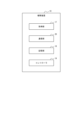
- FIG. 2 is a block diagram showing a schematic configuration of the measuring device of FIG. 1.
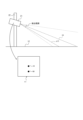
- FIG. FIG. 2 is a state diagram showing a fixed state of the measuring device of FIG. 1;
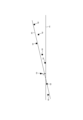
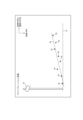
- FIG. 3 is a diagram illustrating a method of setting a virtual surface based on the altitudes of a plurality of calibration points.
- FIG. 3 is a diagram for explaining a method of calculating the altitude of a calibration point based on a comparison between a position based on an image position of the calibration point and a position in real space.
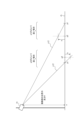
- FIG. 3 is a diagram for explaining a virtual surface correction method.
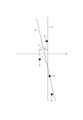
- FIG. 7 is a diagram for explaining an approximate straight line displayed in a correction image. It is a figure which shows the example of the image for correction.
- 3 is a flowchart for explaining a calibration process executed by the controller in FIG. 2.
- FIG. 2 is a block diagram
- FIG. 1 shows a configuration example of a communication system 11 including a measuring device 10 according to an embodiment.
- the communication system 11 is, for example, a safe driving support communication system for an intelligent transport system (ITS).
- ITS intelligent transport system
- the safe driving support communication system is sometimes called a safe driving support system or a safe driving support radio system.
- the measuring device 10 may be a device that observes a specific observation target such as a vehicle or a person on the road in a predetermined area.
- the measuring device 10 is, for example, a roadside device, a surveillance camera device, or the like.
- the measuring device 10 is a roadside device and may be placed near an intersection where a plurality of roads 12 (roadways) intersect to observe the road surface.
- the measuring device 10 may be placed on a roadside other than an intersection.
- the measuring device 10 and a mobile object 13 may communicate with each other wirelessly.
- the plurality of mobile bodies 13 may perform wireless communication with each other.
- the communication system 11 may include electronic devices carried by the pedestrian 14 to perform wireless communication.
- the electronic device is, for example, a mobile terminal device such as a smartphone.
- the measuring device 10 may notify the moving object 13 of support information for supporting safe driving of the driver of the moving object 13.
- the support information may include information regarding an observation target existing on the road to be observed.
- the information regarding the observation target may include the presence or absence of the observation target, the type of the existing observation target, and the distance to the measuring device 10.
- the measuring device 10 may notify an electronic device carried by the pedestrian 14 of the support information.
- the mobile body 13 may acquire various information notified from the measurement device 10 or the like using the electronic equipment mounted thereon.
- the electronic device mounted on the mobile object 13 is, for example, a car navigation system.
- the electronic device mounted on the mobile object 13 may support safe driving of the driver by notifying the driver of a warning or the like based on the support information notified from the measuring device 10.
- the notification to the driver may be the type and position of the object to be observed, such as another moving object 13, near the intersection where the vehicle is proceeding, and the presence of the pedestrian 14 on the crosswalk 16 near the intersection.
- the communication system 11 may support safe driving of the driver of the mobile object 13.
- the moving object 13 is not limited to a car.
- the mobile object 13 may include a motorcycle, a bus, a streetcar, or a bicycle.
- the measuring device 10 measures the distance to an object on a road surface in a predetermined area.
- the object may be an object to be observed.
- the distance to the object may be a distance from an arbitrary origin in real space.
- the arbitrary origin is, for example, the road surface at the position of the imaging unit that provides the measuring device 10 with an image when looking at the three-dimensional real space from vertically above.
- the measuring device 10 may have a measurement mode and a calibration mode as operating modes.
- the measuring device 10 may measure the distance to an object on the road surface in the measurement mode.
- the measuring device 10 may set a virtual surface and generate correction parameters, which will be described later, in the calibration mode.
- the measuring device 10 includes an acquisition section 17, a storage section 18, and a controller 19.
- the measuring device 10 may further include a communication section 20.
- the acquisition unit 17 acquires a captured image from the imaging unit.
- the imaging unit generates an image by imaging a space including the above-described predetermined area.
- the imaging unit is, for example, a monocular camera.
- the monocular camera may be a visible light camera or an FIR camera.
- the imaging unit may generate a captured image at a predetermined frame rate such as 30 fps, for example.
- the imaging unit may be, for example, a plurality of monocular cameras. In such a configuration, the plurality of monocular cameras may be of the same type or may be of different types.
- a camera coordinate system may be defined in the imaging unit.
- the camera coordinate system may be a three-dimensional coordinate system having an origin at an arbitrary position in the imaging unit and three axes that are perpendicular to each other and passing through the origin as coordinate axes.
- the origin of the camera coordinate system is, for example, the intersection of the detection axis of the imaging unit and the imaging element.
- the camera coordinate system includes, for example, an optical axis as a coordinate axis.
- the optical axis may pass through the center of the detection range of the image sensor.
- a camera coordinate system may be determined for each monocular camera, or a camera coordinate system integrated with the plurality of monocular cameras may be determined.
- the imaging unit 21 attaches to a structure 22 having a height that allows capturing an image of a scene including the road 12 outdoors, such as a signal device, utility pole, or street light near an intersection where the road 12 intersects. May be fixed.
- the position and orientation of the imaging unit 21 with respect to the structure 22 may be determined in advance. Furthermore, the position and orientation of the imaging unit 21 may be measured when the imaging unit 21 is actually installed and stored in the storage unit 18.
- the position of the imaging unit 21 means the origin of the camera coordinate system with respect to a reference position in the surrounding space coordinate system defined around the imaging unit 21.
- the attitude of the imaging unit 21 means the inclination of the coordinate axes of the camera coordinate system with respect to the coordinate axes of the surrounding space coordinate system.
- the surrounding space coordinate system may have a vertical direction of the real space and two directions parallel to the horizontal plane and perpendicular to each other as axes. Based on the position and orientation of the imaging unit 21, coordinates and trajectories of planes, lines, etc. in either the camera coordinate system or the surrounding space coordinate system can be converted to the other coordinate system.
- the position and orientation of the imaging unit 21 may be determined such that the optical axis ox of the imaging unit 21 intersects the road surface of the road 12.
- the position and orientation of the imaging unit 21 may be determined such that the detection range of the imaging unit 21 includes a predetermined area determined for the measuring device 10.
- the storage unit 18 includes any storage device such as a RAM (Random Access Memory) and a ROM (Read Only Memory).
- the storage unit 18 may store various programs that cause the controller 19 to function and various information that the controller 19 uses.
- the storage unit 18 stores virtual surfaces.
- the virtual plane is used to measure the distance between the imaging unit 21 and an object on the road surface in the space captured in the captured image ci.
- the virtual plane is, for example, a plane set in the surrounding space coordinate system.
- the entire virtual surface may be a plane, or may be a plurality of continuous planes that are curved.
- an arbitrary position in the captured image ci corresponds to a direction of inclination with respect to the optical axis ox
- an arbitrary image position ap in the captured image ci corresponds to the first straight line sl1 in the camera coordinate system.
- the storage unit 18 may further store at least one of a correction parameter and a correction surface, which will be described later.
- the communication unit 20 may be controlled by the controller 19 to perform wireless communication with the mobile body 13.
- the communication unit 20 may include a communication circuit and an antenna.
- the antenna may be, for example, an omnidirectional antenna.
- the communication unit 20 may perform wireless communication using, for example, the 700 MHz band allocated to the ITS. Further, the communication unit 20 may perform wireless communication using, for example, a wireless LAN (Local Area Network).
- a wireless LAN Local Area Network
- the communication unit 20 may perform various processing such as amplification processing on the signal received by the antenna, and output the processed received signal to the controller 19.
- the communication unit 20 may perform various processing such as amplification processing on the information acquired from the controller 19 and wirelessly transmit the processed transmission signal from the antenna.
- the controller 19 includes one or more processors and memory.
- the processor may include a general-purpose processor that loads a specific program to execute a specific function, and a dedicated processor specialized for specific processing.
- the dedicated processor may include an application specific integrated circuit (ASIC).
- the processor may include a programmable logic device (PLD).
- the PLD may include an FPGA (Field-Programmable Gate Array).
- the controller 19 may be either an SoC (System-on-a-Chip) or an SiP (System In-a-Package) in which one or more processors work together.
- the controller 19 may determine the presence or absence of an object to be observed in a predetermined area based on the image acquired from the imaging unit 21. Specifically, the controller 19 may detect a subject image corresponding to the subject to be observed using known image recognition such as pattern matching on images and deep learning. The controller 19 may determine whether the observation target exists or not by detecting the subject image.
- the controller 19 may identify the type of observation target based on the observation result of the imaging unit 21. Specifically, the controller 19 may detect the subject image and identify the type of observation target by image recognition.
- the controller 19 may obtain the distance to the position of the object to be observed based on the image.
- the acquisition of the distance is, for example, calculation by the controller 19.
- the controller 19 may specifically identify the image position in the two-dimensional coordinate system of the imaging pixels of the portion of the detected object image that is the observation target that touches the road surface.
- the controller 19 may specify the first straight line sl1 corresponding to the specified image position.
- the controller 19 may specify the intersection of the first straight line sl1 and the virtual plane as the position where the object to be observed exists.
- the controller 19 may recognize the distance from the imaging unit 21 to the intersection as a distance based on the virtual plane.
- the controller 19 may calculate the distance between the object and the imaging unit 21 by directly or indirectly correcting the distance based on the virtual plane using a correction parameter described below.
- the controller 19 corrects a portion of the virtual surface in the vicinity of the intersection of the first straight line sl1 and the virtual surface using a correction parameter, and determines the intersection of the corrected portion and the first straight line sl1. You may directly correct the distance based on . Correction of virtual surfaces using correction parameters will be explained later. Alternatively, for example, as will be described later, the controller 19 determines the intersection point between the first straight line sl and a correction surface set by correcting the virtual surface using correction parameters in the calibration mode, thereby determining the The distance may be corrected indirectly.
- the controller 19 may generate support information including the type and distance of the observation target.
- the controller 19 may control the communication unit 20 so as to notify the mobile objects 13 around the measuring device 10 of the generated support information.
- the controller 19 may set a reference horizontal plane.
- the reference horizontal plane may be a horizontal plane at the height of the intersection of the road surface and a straight line extending vertically downward passing through the position of the imaging unit 21 .
- the reference horizontal plane may be set based on a predetermined position of the imaging unit 21 or a position of the imaging unit 21 measured at the time of installation.
- the controller 19 may acquire the position of the imaging section 21 to be measured from an input device connected via the acquisition section 17 or the communication section 20, and may store it in the storage section 18.
- the controller 19 may set a virtual surface.
- any position on the road surface in real space may be determined as a calibration point.
- a target may be placed at the calibration point.
- the target may be imaged by the imaging unit 21.
- the position of the calibration point in real space with respect to the imaging unit 21 may be actually measured.
- the actual measurement of the position may be performed by an operator using an instrument.
- the actual measurement of the position may be performed by a positioning device such as a GNSS (Global Navigation Satellite System) provided at the target.
- GNSS Global Navigation Satellite System
- the controller 19 may detect the image position of the target in the captured image ci of the target, in other words, the image position of the calibration point.
- the controller 19 may set a straight line corresponding to the image position.
- the controller 19 may detect the estimated position of the calibration point in real space based on the image position by detecting the intersection between the straight line and the reference horizontal plane.
- the controller 19 may acquire the position of the calibration point in real space.
- the position in real space may be acquired as a position in the surrounding space coordinate system.
- the controller 19 may acquire the position from an input device connected via the acquisition section 17 or the communication section 20, and may store it in the storage section 18.
- the controller 19 may acquire the position from a positioning device connected via the communication unit 20 and may store it in the storage unit 18.
- the controller 19 may set a virtual plane based on the image position of the calibration point in the captured image ci and the position in real space. In order to set the virtual plane, the controller 19 may calculate the altitude of the calibration point based on the image position in the captured image ci and the position relative to the imaging unit 21 in real space. The altitude may be a height from a reference horizontal plane in the vertical direction. The controller 19 may calculate altitudes for a plurality of different calibration points. As shown in FIG. 4, the controller 19 may set an approximate straight line as based on the altitude h of a plurality of different calibration points cp as a virtual plane.
- the controller 19 compares the estimated position of the calibration point cp in real space, which is detected based on the image position of the calibration point cp, with the position relative to the imaging unit 21 in real space.
- the controller 19 calculates the altitude h of the calibration point cp with respect to the reference horizontal plane rh in real space by comparison. For example, as shown in FIG. 5, the controller 19 connects a second straight line sl2 from the imaging unit 21 to the position p1 based on the captured image ci, and a vertical line passing through the position p2 (actually measured position) with respect to the imaging unit 21 in real space.
- the height of the intersection with the straight line extending in the direction from the reference horizontal plane rh is calculated as the altitude h.
- the altitude h is calculated by equation (1) based on the ratio of similar triangles.
- the origin o is the intersection of a straight line passing through the position of the imaging unit 21 and extending vertically downward and the reference horizontal plane rh.
- h ⁇ (OP1-OP2)/OP1 ⁇ H (1)
- OP1 is the distance from the origin o to the position p1 based on the captured image ci.
- OP2 is the distance from the origin o to the position p2 with respect to the imaging unit 21 in real space.
- H is the height of the position of the imaging unit 21 from the reference horizontal plane rh.
- the altitude h is calculated by equation (2) based on the ratio of similar triangles.
- the controller 19 may set the virtual plane without using the altitude h of the calibration point cp.
- the controller 19 may set the reference horizontal plane rh as a virtual plane.
- the controller 19 may generate a correction parameter based on the difference between the elevation of the virtual surface at any point on the road surface and the elevation of the road surface in real space.
- the correction parameter may be any parameter that causes the correction surface to modify at least a portion of the virtual surface.
- the correction surface is a virtual surface in which a part of the virtual surface is made close to the elevation of the road surface in real space.
- the controller 19 may acquire an arbitrary point on the road surface and the altitude in real space from an input device connected via the acquisition section 17 or the communication section 20, and may store it in the storage section 18.
- the controller 19 when acquiring the elevation H1 in real space at an arbitrary point sp on the road surface, the controller 19 creates an approximate straight line such that the correction surface cs passes through the road surface in real space at the arbitrary point sp. Correct the virtual surface represented as as. In correcting the approximate straight line as, the controller 19 may also correct a portion near an arbitrary point sp. The controller 19 may correct the portion near the arbitrary point sp into a curved shape. Alternatively, the controller 19 may correct the portion near the arbitrary point sp into a straight line. The controller 19 may maintain the shape of the approximate straight line as in a portion other than the vicinity of the arbitrary point sp. The controller 19 may generate a correction parameter for correcting the virtual surface as described above based on the difference between the elevation of the virtual surface and the elevation H1 of the road surface in real space at an arbitrary point sp.
- the controller 19 may generate a correction image for inputting an arbitrary point on the road surface and the altitude H1 in real space.
- the correction image is an image of an approximate straight line as at an arbitrary position in a direction that intersects a plane parallel to the optical axis direction of the imaging unit 21 and the vertical direction in real space and parallel to the horizontal plane in real space, as seen from the direction. It is.
- an approximate straight line as at an arbitrary position in a direction intersecting the plane fs1 is an intersection line between a plane fs2 perpendicular to the direction and a virtual plane at an arbitrary position in a direction intersecting the plane fs1. It is. Therefore, the correction image is an image showing the approximate straight line as in the plane fs2.
- the controller 19 may display the correction image on a display connected via the acquisition unit 17 or the communication unit 20.
- the altitude at any position in the vertical direction may be entered into the input device by an operator checking the display.
- the input device may be a touch panel provided on a display that displays the correction image.
- the controller 19 may acquire the altitude at an arbitrary position in the vertical direction from the input device via the acquisition unit 17 or the communication unit 20 as the altitude H1 in real space for correcting the approximate straight line as.
- the input device is a touch panel, by pressing an arbitrary position in the correction image with a pointer pen or the like, an arbitrary position in the vertical direction and the altitude at the position may be detected.
- the position at which the controller 19 acquires the altitude for correcting the virtual plane may be arbitrarily determined by the operator, but the position of the calibration point cp may be used together with the altitude h.
- At least a portion of the virtual plane may be corrected along a straight line parallel to the lane in the space imaged by the imaging unit 21.
- Lanes may include traffic lanes and sidewalks. Therefore, any point for generating a correction parameter may be set on a straight line parallel to the lane in space. Further, a direction intersecting the plane fs1 parallel to the optical axis direction of the imaging unit 21 and the vertical direction in real space may be determined so that the above-mentioned correction image is parallel to the lane.
- the virtual plane may be corrected for each of the plurality of lanes in the space imaged by the imaging unit 21. Therefore, arbitrary points for generating correction parameters may be set for each of a plurality of lanes. Further, the correction parameters may be generated for each of a plurality of lanes. Further, the above-described correction images may be generated for each of a plurality of lanes so as to be parallel to the lanes.
- the virtual plane may also be set for each of a plurality of lanes.
- the calibration process is started by switching the operation mode to the calibration mode using an input device after the measurement device 10 is installed. Note that in the calibration mode, a display and an input device are connected to the measuring device 10.
- step S100 the controller 19 issues an input request for the position of the calibration point cp to the display. After granting, the process proceeds to step S101.
- step S101 the controller 19 determines whether an imaging command requesting imaging of the target at the calibration point cp has been obtained via the input device. If not acquired, the process returns to step S101. If so, the process proceeds to step S102.
- step S102 the controller 19 acquires the captured image ci from the imaging unit 21.
- the controller 19 acquires the captured image ci by notifying an imaging command.
- the controller 19 acquires the captured image ci of the frame immediately after acquiring the imaging command in step S101. After acquisition, the process proceeds to step S102.
- step S103 the controller 19 determines the position of the target at the calibration point cp based on the position of the calibration point cp input requested in step S100 relative to the imaging unit 21 and the position of the target in the captured image ci acquired in step S102. Calculate the altitude h. After calculating the altitude h, the process proceeds to step S104.
- step S104 the controller 19 provides the display with a question as to whether or not to add a calibration point. After the grant, the process proceeds to step S105.
- step S105 the controller 19 determines whether the input indicating that a calibration point CP has been added or the input indicating that there has been no addition has been obtained. If an input is obtained indicating that there is an addition, the process returns to step S101. If an input is obtained indicating that there is no addition, the process proceeds to step S106.
- step S106 the controller 19 sets a virtual plane based on the altitude h calculated in step S103. After the settings, the process proceeds to step S107.
- step S107 the controller 19 generates a correction image including an approximate straight line as corresponding to the virtual plane set in step S106. Further, the controller 19 applies the correction image to the display and causes it to be displayed. After generation, the process proceeds to step S108.
- step S108 the controller 19 determines whether the altitude H1 of an arbitrary position perpendicular to the vertical direction in the correction image has been acquired. If so, the process proceeds to step S109. If not, the process proceeds to step S110.
- step S109 the controller 19 generates a correction parameter based on the altitude on the virtual plane set in step S106 and the altitude H1 whose acquisition was confirmed in step S108. Furthermore, the controller 19 corrects the virtual surface based on the correction parameters. Further, the controller 19 stores the corrected virtual plane in the storage unit 18. After correction, the process proceeds to step S110.
- step S110 the controller 19 determines whether an input to end the calibration mode has been obtained. If not acquired, the process returns to step S107. If it has been acquired, the calibration process ends.
- the measuring device 10 of this embodiment configured as described above includes a storage unit 18 that stores a virtual plane used to measure the distance between an object on a road surface in space and the imaging unit 21, and a The controller 19 generates a correction parameter based on the difference between the elevation of the virtual surface and the elevation H1 of the road surface in real space, and corrects the distance based on the virtual surface using the correction parameter.
- the measuring device 10 corrects the distance between the virtual surface and the actual road surface unevenness based on the virtual surface using the image position of the subject image on the road surface. Therefore, the measuring device 10 can improve the accuracy of distance measurement using images.
- the measuring device 10 of the present embodiment indirectly corrects the distance using a correction surface cs obtained by correcting a virtual surface using correction parameters.
- the measuring device 10 generates the correction surface cs in advance and corrects the distance based on the correction surface cs at the time of measurement, so that the measurement device 10 has a configuration in which the distance is directly corrected using the correction parameter every time the measurement is performed.
- the time required to correct the distance after acquiring the captured image ci can be made faster.
- the virtual plane is set based on the image position of the calibration point cp in the captured image ci at an arbitrary position on the road surface and the position with respect to the imaging unit 21 in real space.
- a virtual plane to be used for distance measurement is set based on the position of the calibration point cp in real space, so compared to a configuration in which an arbitrary plane is set as a virtual plane.
- the accuracy of distance measurement using images can be further improved.
- a correction image viewed from this direction is generated, and the elevation at an arbitrary position of the approximate straight line as in the correction image is obtained as the elevation H1 in real space.
- an arbitrary point for generating a correction parameter is set on a straight line parallel to a lane in the space, and is set for each of a plurality of lanes in the space, and a plurality of correction parameters are set. generated for each lane. Correcting the elevation at many points on the road surface causes an increase in the processing load on the controller 19.
- the measuring device 10 having the above-mentioned configuration corrects the altitude at a position along the lane, so it can measure distance with the required measurement accuracy while suppressing an excessive increase in processing load. obtain.
- the embodiment of the measuring device 10 has been described above, but in addition to the method or program for implementing the device, the embodiment of the present disclosure also includes a storage medium (for example, an optical disk, a magneto-optical disk, etc.) on which the program is recorded. , CD-ROM, CD-R, CD-RW, magnetic tape, hard disk, memory card, etc.).
- a storage medium for example, an optical disk, a magneto-optical disk, etc.
- CD-ROM, CD-R, CD-RW magnetic tape, hard disk, memory card, etc.
- the implementation form of a program is not limited to an application program such as an object code compiled by a compiler or a program code executed by an interpreter, but may also be in the form of a program module incorporated into an operating system. good.
- the program may or may not be configured such that all processing is performed only in the CPU on the control board.
- the program may be configured such that part or all of the program is executed by an expansion board attached to the board or another processing unit mounted in an expansion unit, as necessary.
- the measuring device 10 is configured to be a separate device from the imaging section 21, but the measuring device 10 may include the imaging section 21.
- embodiments according to the present disclosure are not limited to any of the specific configurations of the embodiments described above. Embodiments of the present disclosure extend to any novel features or combinations thereof described in this disclosure, or to any novel methods or process steps or combinations thereof described. be able to.
- descriptions such as “first” and “second” are identifiers for distinguishing the configurations.
- the numbers in the configurations can be exchanged.
- the first straight line can exchange the identifiers “first” and “second” with the second straight line.
- the exchange of identifiers takes place simultaneously.
- the configurations are distinguished.
- Identifiers may be removed.
- Configurations with removed identifiers are distinguished by codes.
- the description of identifiers such as “first” and “second” in this disclosure should not be used to interpret the order of the configuration or to determine the existence of lower-numbered identifiers.
Landscapes
- Physics & Mathematics (AREA)
- Electromagnetism (AREA)
- Engineering & Computer Science (AREA)
- General Physics & Mathematics (AREA)
- Radar, Positioning & Navigation (AREA)
- Remote Sensing (AREA)
- Length Measuring Devices By Optical Means (AREA)
Abstract
測定装置は取得部と記憶部とコントローラとを有する。取得部は撮像画像を撮像部から取得する。記憶部は仮想面を記憶する。仮想面は空間内の路面上の物体と撮像部との距離の測定に利用される。コントローラは路面の任意の地点における仮想面の標高と路面の実空間の標高との差分に基づき補正パラメータを生成する。コントローラは仮想面に基づく距離を補正パラメータにより補正する。
Description
本出願は、2022年3月29日に日本国に特許出願された特願2022-054641の優先権を主張するものであり、この先の出願の開示全体をここに参照のために取り込む。
本発明は、測定装置及び測定方法に関するものである。
監視用カメラを設置した空間内における監視用カメラの位置及び姿勢に基づいて、カメラ座標系における位置を、実空間における路面上の位置に変換することが知られている。カメラ座標系における位置を実空間における路面上の位置に変換するためには、道路の平面パラメータを用いることが知られている(特許文献1参照)。
第1の観点による測定装置は、
所定の領域を含む空間の撮像画像を撮像部から取得する取得部と、
前記空間内の路面上の物体と前記撮像部との距離の測定に利用する仮想面を記憶する記憶部と、
前記路面の任意の地点における仮想面の標高と該路面の実空間の標高との差分に基づき補正パラメータを生成し、前記仮想面に基づく前記距離を前記補正パラメータにより補正するコントローラと、を備える。
所定の領域を含む空間の撮像画像を撮像部から取得する取得部と、
前記空間内の路面上の物体と前記撮像部との距離の測定に利用する仮想面を記憶する記憶部と、
前記路面の任意の地点における仮想面の標高と該路面の実空間の標高との差分に基づき補正パラメータを生成し、前記仮想面に基づく前記距離を前記補正パラメータにより補正するコントローラと、を備える。
第2の観点による測定方法は、
撮像部が撮像する空間内の路面上の物体と前記撮像部との距離の測定に利用する仮想面を記憶し、
前記空間の撮像画像を前記撮像部から取得し、
前記路面の任意の地点における仮想面の標高と該路面の実空間の標高との差分に基づき補正パラメータを生成し、
前記仮想面に基づく前記距離を、前記補正パラメータにより補正する。
撮像部が撮像する空間内の路面上の物体と前記撮像部との距離の測定に利用する仮想面を記憶し、
前記空間の撮像画像を前記撮像部から取得し、
前記路面の任意の地点における仮想面の標高と該路面の実空間の標高との差分に基づき補正パラメータを生成し、
前記仮想面に基づく前記距離を、前記補正パラメータにより補正する。
以下、本開示を適用した測定装置の実施形態について、図面を参照して説明する。
図1は、一実施形態に係る測定装置10を備える通信システム11の構成例を示す。通信システム11は、例えば、高度道路交通システム(ITS:Intelligent Transport Systems)の安全運転支援通信システムである。安全運転支援通信システムは、安全運転支援システムと呼ばれたり、安全運転支援無線システムと呼ばれたりする。
測定装置10は、所定の領域における路上の車両、人等の特定の観察対象を観察する装置であってよい。測定装置10は、例えば路側機、監視カメラ装置等である。本実施形態において、測定装置10は、路側機であって、複数の道路12(車道)が交差する交差点の近くに配置されて、路面を観察してよい。測定装置10は、交差点以外の路側に配置されてよい。
通信システム11では、測定装置10と、道路12を走る自動車等の移動体13とが、互いに無線通信を行ってよい。複数の移動体13は、互いに無線通信を行ってよい。通信システム11では、歩行者14が所持する電子機器を含んで無線通信を行ってよい。電子機器は、例えば、スマートフォン等の携帯端末装置である。
測定装置10は、移動体13の運転者の安全運転を支援するための支援情報を、移動体13に通知してよい。支援情報は、観察する路上に存在する観察対象に関する情報を含んでよい。観察対象に関する情報は、観察対象の存否、存在する観察対象の種類、及び測定装置10までの距離を含んでよい。測定装置10は、支援情報を歩行者14が所持する電子機器に通知してよい。
移動体13は、搭載している電子機器によって、測定装置10等から通知される各種情報を取得してよい。移動体13が搭載する電子機器は、例えばカーナビゲーションシステム等である。移動体13が搭載する電子機器は、測定装置10から通知される支援情報に基づいて、警告等の通知を運転者に行うことによって、運転者の安全運転を支援してよい。運転者への通知は、進行する交差点近傍の他の移動体13等の観察対象の種類及び位置、並びに交差点近傍の横断歩道16の歩行者14の存在であってよい。
上記のように、通信システム11は、移動体13の運転者の安全運転を支援してよい。移動体13は、自動車に限定されない。例えば、移動体13は、自動二輪車、バス、路面電車、自転車を含み得る。
以下に、測定装置10の詳細について説明する。測定装置10は、所定の領域における路面上の物体までの距離を測定する。物体は、観察対象であってよい。物体までの距離は、実空間における任意の原点からの距離であってよい。任意の原点は、例えば、3次元の実空間を鉛直上方から見た、測定装置10に画像を提供する撮像部の位置における路面である。
測定装置10は、動作モードとして、測定モード及びキャリブレーションモードを有してよい。測定装置10は、測定モードにおいて、路面上の物体までの距離を測定してよい。測定装置10は、キャリブレーションモードにおいて、後述する仮想面の設定、補正パラメータの生成を行ってよい。
図2に示すように、測定装置10は、取得部17、記憶部18、及びコントローラ19、を含んで構成される。測定装置10は、更に、通信部20を含んでよい。
取得部17は、撮像部から撮像画像を取得する。撮像部は、前述の所定の領域を含む空間を撮像することにより画像を生成する。撮像部は、例えば、単眼カメラである。単眼カメラは、可視光カメラ、FIRカメラであってよい。撮像部は、例えば、30fps等の所定のフレームレートで撮像画像を生成してよい。又は、撮像部は、例えば、複数の単眼カメラであってよい。このような構成において、複数の単眼カメラは同じ種類であってよく、異なる種類であってよい。
撮像部には、カメラ座標系が定められていてよい。カメラ座標系は、撮像部における任意の位置を原点とし、当該原点を通る互いに垂直な3軸を座標軸とする三次元座標系であってよい。カメラ座標系の原点は、例えば、撮像部の検出軸と撮像素子の交点である。カメラ座標系は、例えば、光軸を座標軸に含む。光軸は、撮像素子の検出範囲の中心を通ってよい。又、撮像部が、複数の単眼カメラである構成において、単眼カメラ各々にカメラ座標系が定められていてよく、複数の単眼カメラに統合したカメラ座標系が定められていてよい。
図3に示すように、撮像部21は、例えば、道路12が交差する交差点付近の信号装置、電柱、街灯等の、屋外において道路12を含む光景を撮像可能な高さを有する構造物22に固定されてよい。構造物22に対する撮像部21の位置及び姿勢は、事前に定められてよい。更には、撮像部21の位置及び姿勢は、実際に撮像部21が設置された際に測定されて、記憶部18に格納されていてよい。
撮像部21の位置は、撮像部21の周囲に定められる周囲空間座標系において基準となる位置に対するカメラ座標系の原点を意味する。撮像部21の姿勢は、周囲空間座標系の座標軸に対するカメラ座標系の座標軸の傾きを意味する。周囲空間座標系は、実空間の鉛直方向と、水平面に平行且つ互いに垂直な2方向とを軸としてよい。撮像部21の位置及び姿勢に基づいて、カメラ座標系及び周囲空間座標系のいずれかにおける、座標と面及び線等の軌跡とは他方の座標系に変換され得る。
撮像部21の位置及び姿勢は、撮像部21の光軸oxが道路12の路面に交差するように定められてよい。撮像部21の位置及び姿勢は、撮像部21の検出範囲が測定装置10に対して定められる所定の領域を含むように、定められてよい。
図2において、記憶部18は、例えば、RAM(Random Access Memory)およびROM(Read Only Memory)など、任意の記憶デバイスを含む。記憶部18は、コントローラ19を機能させる多様なプログラム、およびコントローラ19が用いる多様な情報を記憶してよい。
記憶部18は、仮想面を記憶する。仮想面は、撮像画像ciに撮像される空間内の路面上の物体と撮像部21との距離の測定に利用される。仮想面は、例えば、周囲空間座標系において、設定される面である。仮想面は、全体が平面であってよく、屈曲しながら連続する複数の平面であってよい。
図3に示すように、撮像画像ciにおける任意の位置は光軸oxに対する傾斜方向に対応しているので、撮像画像ciにおける任意の画像位置apはカメラ座標系における第1の直線sl1に対応させ得る。当該第1の直線sl1と仮想面との交点が路面上の物体の位置として検出され得るので、検出された位置と撮像部21の位置とにより、路面上の物体と撮像部21との距離が測定され得る。
記憶部18は、更に、後述する補正パラメータ及び補正面の少なくとも一方を記憶してよい。
通信部20は、コントローラ19によって制御されて移動体13と無線通信を行ってよい。通信部20は、通信回路と、アンテナとで構成されてよい。アンテナは例えば無指向性のアンテナであってよい。通信部20は、例えばITSに割り当てられている700MHz帯を使用して無線通信を行ってよい。また、通信部20は、例えば無線LAN(Local Area Network)を用いて無線通信を行ってよい。
通信部20は、アンテナで受信した信号に対して増幅処理などの各種処理を行い、処理後の受信信号をコントローラ19に出力してよい。通信部20は、コントローラ19から取得する情報に対して増幅処理などの各種処理を行って、処理後の送信信号をアンテナから無線送信してよい。
コントローラ19は、1以上のプロセッサおよびメモリを含む。プロセッサは、特定のプログラムを読み込ませて特定の機能を実行する汎用のプロセッサ、および特定の処理に特化した専用のプロセッサを含んでよい。専用のプロセッサは、特定用途向けIC(ASIC;Application Specific Integrated Circuit)を含んでよい。プロセッサは、プログラマブルロジックデバイス(PLD;Programmable Logic Device)を含んでよい。PLDは、FPGA(Field-Programmable Gate Array)を含んでよい。コントローラ19は、1つ又は複数のプロセッサが協働するSoC(System-on-a-Chip)、およびSiP(System In a Package)のいずれかであってもよい。
測定モードにおいて、コントローラ19は、撮像部21から取得する画像に基づいて、所定の領域における観察対象である物体の存否を判別してよい。コントローラ19は、具体的には、画像に対するパターンマッチング、深層学習等の公知の画像認識により、観察対象の被写体に対応する被写体像を検出してよい。コントローラ19は、被写体像の検出により、観察対象の存否を判別してよい。
測定モードにおいて、コントローラ19は、観察対象が存在する場合、撮像部21の観察結果に基づいて観察対象の種類を識別してよい。コントローラ19は、具体的には、被写体像の検出とともに画像認識により観察対象の種類を識別してよい。
測定モードにおいて、コントローラ19は、観察対象が存在する場合、画像に基づいて観察対象である物体の存在する位置までの距離を取得してよい。距離の取得は、例えば、コントローラ19による算出である。
測定モードにおいて、コントローラ19は、具体的には、検出された観察対象である被写体像の路面に接地する部分の、撮像画素の二次元座標系における画像位置を特定してよい。コントローラ19は、特定した画像位置に対応する第1の直線sl1を特定してよい。コントローラ19は、当該第1の直線sl1と仮想面との交点を、観察対象である物体の存在する位置として特定してよい。コントローラ19は、撮像部21から交点までの距離を、仮想面に基づく距離として認定してよい。コントローラ19は、仮想面に基づく距離を、後述する補正パラメータを用いて直接的に又は間接的に補正することにより、当該物体と撮像部21との距離を算出してよい。
例えば、コントローラ19は、第1の直線sl1及び仮想面の交点近傍における当該仮想面の部分を補正パラメータにより補正し、補正した当該部分と第1の直線sl1との交点を求めることにより、仮想面に基づく距離を直接的に補正してよい。補正パラメータを用いた仮想面の補正は、後に説明される。又は、例えば、コントローラ19は、後述するように、キャリブレーションモードにおいて補正パラメータにより仮想面を補正することにより設定される補正面と第1の直線slとの交点を求めることにより、仮想面に基づく距離を間接的に補正してよい。
測定モードにおいて、コントローラ19は、少なくとも1つの観察対象が存在する場合、観察対象の種類及び距離を含む支援情報を生成してよい。コントローラ19は、生成した支援情報を、測定装置10の周囲の移動体13に通知するように、通信部20を制御してよい。
キャリブレーションモードにおいて、コントローラ19は、基準水平面を設定してよい。基準水平面は、撮像部21の位置を通る鉛直下方に延びる直線と路面との交点の高さ位置における水平面であってよい。基準水平面は、予め定められる撮像部21の位置又は設置時に測定される撮像部21の位置に基づいて設定されてよい。コントローラ19は、測定される撮像部21の位置を、取得部17又は通信部20を介して接続される入力デバイスから取得してよく、記憶部18に格納してよい。
キャリブレーションモードにおいて、コントローラ19は、仮想面を設定してよい。仮想面の設定のために、実空間における路面上の任意の位置がキャリブレーションポイントに定められてよい。キャリブレーションポイントに、ターゲットが配置されてよい。ターゲットが撮像部21に撮像されてよい。実空間におけるキャリブレーションポイントの撮像部21に対する位置が実測されてよい。当該位置の実測は、オペレータにより器具を用いて行われてよい。又は、当該位置の実測は、ターゲットに設けるGNSS(Global Navigation Satellite System)等の測位装置により行われてよい。
キャリブレーションモードにおいて、コントローラ19は、ターゲットを撮像した撮像画像ciにおけるターゲットの画像位置、言換えるとキャリブレーションポイントの画像位置を検出してよい。コントローラ19は、画像位置に対応する直線を設定してよい。コントローラ19は、当該直線と基準水平面との交点を検出することにより、画像位置に基づくキャリブレーションポイントの実空間における推定位置を検出してよい。
キャリブレーションモードにおいて、コントローラ19は、キャリブレーションポイントの実空間における位置を取得してよい。実空間における位置は周囲空間座標系における位置として取得してよい。コントローラ19は、当該位置を取得部17又は通信部20を介して接続される入力デバイスから取得してよく、記憶部18に格納してよい。又は、コントローラ19は、当該位置を、通信部20を介して接続される測位装置から取得してよく、記憶部18に格納してよい。
キャリブレーションモードにおいて、コントローラ19は、キャリブレーションポイントの、撮像画像ciにおける画像位置と、実空間における位置とに基づいて、仮想面を設定してよい。コントローラ19は、仮想面の設定のために、撮像画像ciにおける画像位置と、実空間における撮像部21に対する位置とに基づいて、キャリブレーションポイントの標高を算出してよい。標高は、鉛直方向における基準水平面からの高さであってよい。コントローラ19は、複数の異なるキャリブレーションポイントに対して、標高を算出してよい。図4に示すように、コントローラ19は、複数の異なるキャリブレーションポイントcpの標高hに基づく近似直線asを、仮想面として設定してよい。
キャリブレーションポイントcpの標高hの算出方法を以下に説明する。コントローラ19は、キャリブレーションポイントcpの画像位置に基づいて検出されるキャリブレーションポイントcpの実空間における推定位置と、実空間における撮像部21に対する位置とを比較する。コントローラ19は、比較により、実空間において基準水平面rhに対するキャリブレーションポイントcpの標高hを算出する。例えば、図5に示すように、コントローラ19は、撮像部21から撮像画像ciに基づく位置p1に向かう第2の直線sl2と、実空間における撮像部21に対する位置p2(実測の位置)を通り鉛直方向に延びる直線との交点の、基準水平面rhからの高さを標高hとして算出する。
より具体的には、撮像画像に基づく位置p1が実空間における撮像部21に対する位置p2よりも原点oから遠い場合、相似する三角形の比により、標高hは(1)式により算出される。原点oは、撮像部21の位置を通る鉛直下方に延びる直線と基準水平面rhの交点である。
h={(OP1-OP2)/OP1}×H (1)
ただし、OP1は、原点oから撮像画像ciに基づく位置p1までの距離である。OP2は、原点oから実空間における撮像部21に対する位置p2までの距離である。Hは、基準水平面rhからの撮像部21の位置の高さである。
ただし、OP1は、原点oから撮像画像ciに基づく位置p1までの距離である。OP2は、原点oから実空間における撮像部21に対する位置p2までの距離である。Hは、基準水平面rhからの撮像部21の位置の高さである。
又、実空間における撮像部21に対する位置p2が撮像画像ciに基づく位置p1よりも原点oから遠い場合、相似する三角形の比により、標高hは(2)式により算出される。
h={(OP1-OP2)/OP1}×H (2)
コントローラ19は、キャリブレーションポイントcpの標高hを用いずに、仮想面を設定してよい。例えば、コントローラ19は、基準水平面rhを仮想面として設定してもよい。
キャリブレーションモードにおいて、コントローラ19は、路面の任意の地点における仮想面の標高と、当該路面の実空間の標高との差分に基づいて補正パラメータを生成してよい。補正パラメータは、仮想面の少なくとも一部を補正面に修正させる任意のパラメータであってよい。補正面は、仮想面の一部を実空間における路面の標高に近づけた仮想の面である。コントローラ19は、路面の任意の地点及び実空間の標高を、取得部17又は通信部20を介して接続される入力デバイスから取得してよく、記憶部18に格納してよい。
例えば、図6に示すように、コントローラ19は、路面における任意の地点spにおける実空間の標高H1を取得する場合、補正面csは任意の地点spにおいて実空間の路面を通るように、近似直線asとして表される仮想面を補正する。コントローラ19は、近似直線asの補正において、任意の地点sp近傍の部分も補正してよい。コントローラ19は、当該任意の地点sp近傍の部分を曲線状に補正してよい。又は、コントローラ19は、当該任意の地点sp近傍の部分を直線状に補正してよい。コントローラ19は、任意の地点sp近傍以外の部分を近似直線asの形状を維持させてよい。コントローラ19は、任意の地点spにおける、仮想面の標高と、当該路面の実空間の標高H1との差分に基づいて、上述のように仮想面を補正する補正パラメータを生成してよい。
キャリブレーションモードにおいて、コントローラ19は、路面の任意の地点及び実空間の標高H1を入力させるための補正用画像を生成してよい。補正用画像は、撮像部21の光軸方向と実空間における鉛直方向とに平行な平面に交差し且つ実空間における水平面に平行な方向における任意の位置の近似直線asを当該方向から見た画像である。図7に示すように、当該平面fs1に交差する方向における任意の位置の近似直線asは、当該平面fs1に交差する方向における任意の位置の当該方向に垂直な平面fs2と仮想面との交線である。したがって、補正用画像は、平面fs2における近似直線asを示す画像である。
図8に示すように、補正用画像においては、鉛直方向に垂直な方向の任意の位置を指定して、標高、言換えると鉛直方向における路面の位置を指定可能である。具体例を以下に説明する。コントローラ19は、補正用画像を取得部17又は通信部20を介して接続されるディスプレイに表示してよい。ディスプレイを確認するオペレータにより垂直な方向の任意の位置における標高が入力デバイスに入力されてよい。当該入力デバイスは補正用画像を表示するディスプレイに設けられたタッチパネルであってよい。コントローラ19は、当該入力デバイスから取得部17又は通信部20を介して、垂直な方向の任意の位置における標高を、近似直線asを補正するための実空間における標高H1として取得してよい。入力デバイスがタッチパネルである構成においては、補正用画像における任意の位置をポインタペン等で押圧することにより、垂直な方向の任意の位置及び当該位置における標高が検出されてよい。
補正用画像において、仮想面を補正するための標高をコントローラ19に取得させる位置は、オペレータによって任意に決められてよいが、キャリブレーションポイントcpの位置が標高hとともに用いられてよい。
キャリブレーションモードにおいて、仮想面の少なくとも一部は、撮像部21が撮像する空間内におけるレーンに平行な直線に沿って補正されてよい。レーンは、車線及び歩道を含んでよい。したがって、補正パラメータを生成するための任意の地点は、空間内におけるレーンに平行な直線上に設定されてよい。又、上述の補正用画像が当該レーンに平行となるように、撮像部21の光軸方向と実空間における鉛直方向とに平行な平面fs1に交差する方向が定められてよい。
キャリブレーションモードにおいて、仮想面は、撮像部21が撮像する空間内の複数のレーン別に補正されてよい。したがって、補正パラメータを生成するための任意の地点は、複数のレーン別に設定されてよい。又、補正パラメータは複数のレーン別に生成されてよい。又、上述の補正用画像は、複数のレーン別に、当該レーンに平行となるように生成されてよい。
キャリブレーションモードにおいて、複数の車線別に補正パラメータが生成される構成においては、仮想面も複数のレーン別に設定されてよい。
次に、本実施形態においてコントローラ19が実行する、キャリブレーション処理について、図9のフローチャートを用いて説明する。キャリブレーション処理は、測定装置10の設置後に、入力デバイスを用いて動作モードをキャリブレーションモードに切替えることにより開始する。なお、キャリブレーションモードにおいては、測定装置10にディスプレイ及び入力デバイスが接続される。
ステップS100において、コントローラ19は、キャリブレーションポイントcpの位置の入力要求をディスプレイに付与する。付与後、プロセスはステップS101に進む。
ステップS101では、コントローラ19は、入力デバイスを介してキャリブレーションポイントcpのターゲットの撮像を要求する撮像指令を取得しているか否かを判別する。取得していない場合、プロセスはステップS101に戻る。取得している場合、プロセスはステップS102に進む。
ステップS102では、コントローラ19は、撮像部21から撮像画像ciを取得する。なお、撮像部21がコントローラ19の制御により駆動する構成においては、コントローラ19は撮像指令を通知することにより撮像画像ciを取得する。撮像部21がコントローラ19の制御によらずに撮像画像ciを生成する構成においては、コントローラ19はステップS101における撮像指令を取得した直後のフレームの撮像画像ciを取得する。取得後、プロセスはステップS102に進む。
ステップS103では、コントローラ19は、ステップS100において入力要求したキャリブレーションポイントcpの撮像部21に対する位置と、ステップS102において取得した撮像画像ciにおけるターゲットの位置とに基づいて、キャリブレーションポイントcpにおけるターゲットの標高hを算出する。標高hの算出後、プロセスはステップS104に進む。
ステップS104では、コントローラ19は、キャリブレーションポイントの追加の有無の問いかけをディスプレイに付与する。付与後、プロセスはステップS105に進む。
ステップS105では、コントローラ19は、キャリブレーションポイントcpの追加があることを示す入力、又は追加がないことを示す入力のいずれを取得しているかを判別する。追加があることを示す入力を取得する場合、プロセスはステップS101に戻る。追加がないことを示す入力を取得する場合、プロセスはステップS106に進む。
ステップS106では、コントローラ19は、ステップS103において算出した標高hに基づいて、仮想面を設定する。設定後、プロセスはステップS107に進む。
ステップS107では、コントローラ19は、ステップS106において設定した仮想面に相当する近似直線asを含む補正用画像を生成する。更に、コントローラ19は、補正用画像をディスプレイに付与して、表示させる。生成後、プロセスはステップS108に進む。
ステップS108では、コントローラ19は、補正用画像における鉛直方向に垂直な任意の位置の標高H1を取得しているか否かを判別する。取得している場合、プロセスはステップS109に進む。取得していない場合、プロセスはステップS110に進む。
ステップS109では、コントローラ19は、ステップS106において設定した仮想面における標高と、ステップS108において取得が確認された標高H1とに基づいて補正パラメータを生成する。更に、コントローラ19は、補正パラメータに基づいて仮想面を補正する。更に、コントローラ19は、補正した仮想面を記憶部18に格納する。補正後、プロセスはステップS110に進む。
ステップS110では、コントローラ19は、キャリブレーションモードを終了する入力を取得しているか否かを判別する。取得していない場合、プロセスはステップS107に戻る。取得している場合、キャリブレーション処理は終了する。
以上のような構成の本実施形態の測定装置10は、空間内の路面上の物体と撮像部21との距離の測定に利用する仮想面を記憶する記憶部18と、路面の任意の地点における仮想面の標高と当該路面の実空間の標高H1との差分に基づき補正パラメータを生成し、仮想面に基づく距離を補正パラメータにより補正するコントローラ19とを備える。このような構成により、測定装置10は、仮想面に対する実際の路面の凹凸を、路面上の被写体像の画像位置を用いた仮想面に基づく距離を補正する。したがって、測定装置10は、画像を用いた距離の測定精度を向上させ得る。
また、本実施形態の測定装置10は、仮想面を補正パラメータによって補正した補正面csを用いて間接的に距離を補正する。このような構成により、測定装置10は、事前に補正面csを生成し、測定時には補正面csに基づいて距離を補正するので、測定の度に補正パラメータを用いて直接距離の補正を行う構成に比べて、撮像画像ciの取得後から距離の補正に係る時間を高速化し得る。
また、本実施形態の測定装置10では、仮想面は路面上の任意の位置におけるキャリブレーションポイントcpの撮像画像ciにおける画像位置と実空間における撮像部21に対する位置とに基づいて設定される。このような構成により、測定装置10は、実空間におけるキャリブレーションポイントcpの位置に基づいて、距離の測定に利用する仮想面が設定されるので、任意の平面を仮想面として設定する構成に比べて、画像を用いた距離の測定精度を更に向上させ得る。
また、本実施形態の測定装置10では、撮像部21の光軸方向と実空間における鉛直方向とに平行な平面fs1に交差し且つ実空間における水平面に平行な方向における任意の位置の近似直線asを、当該方向から見た補正用画像を生成し、補正用画像内の近似直線asの任意の位置における標高を、実空間の標高H1として取得する。このような構成により、測定装置10は、キャリブレーションを行うオペレータに仮想面の形状を視認させ得る。それゆえ、測定装置10は、オペレータに実空間の路面と仮想面の形状を比較させることにより、実空間の標高H1を、視覚的に仮想面に反映させ得る。したがって、測定装置10は、オペレータに容易に仮想面の補正を行わせ得る。
また、本実施形態の測定装置10では、補正パラメータを生成するための任意の地点は間内における車線に平行な直線上に設定され、且つ空間内における複数の車線別に設定され、補正パラメータは複数の車線別に生成される。路面の多数の地点における標高の補正は、コントローラ19における処理負荷の増加を引起こす。このような事象に対して、上述の構成を有する測定装置10は、標高の補正を車線に沿った位置で行うので、処理負荷の過大な増加を抑えながら、求められる測定精度で距離を測定し得る。
以上、測定装置10の実施形態を説明してきたが、本開示の実施形態としては、装置を実施するための方法又はプログラムの他、プログラムが記録された記憶媒体(一例として、光ディスク、光磁気ディスク、CD-ROM、CD-R、CD-RW、磁気テープ、ハードディスク、又はメモリカード等)としての実施態様をとることも可能である。
また、プログラムの実装形態としては、コンパイラによってコンパイルされるオブジェクトコード、インタプリタにより実行されるプログラムコード等のアプリケーションプログラムに限定されることはなく、オペレーティングシステムに組み込まれるプログラムモジュール等の形態であってもよい。さらに、プログラムは、制御基板上のCPUにおいてのみ全ての処理が実施されるように構成されてもされなくてもよい。プログラムは、必要に応じて基板に付加された拡張ボード又は拡張ユニットに実装された別の処理ユニットによってその一部又は全部が実施されるように構成されてもよい。
本開示に係る実施形態について説明する図は模式的なものである。図面上の寸法比率等は、現実のものとは必ずしも一致していない。
本開示に係る実施形態について、諸図面及び実施例に基づき説明してきたが、当業者であれば本開示に基づき種々の変形又は改変を行うことが可能であることに注意されたい。従って、これらの変形又は改変は本開示の範囲に含まれることに留意されたい。例えば、各構成部等に含まれる機能等は論理的に矛盾しないように再配置可能であり、複数の構成部等を1つに組み合わせたり、或いは分割したりすることが可能である。
例えば、本実施形態において、測定装置10は、撮像部21とは別の装置である構成であるが、測定装置10が撮像部21を含む構成であってよい。
本開示に記載された構成要件の全て、及び/又は、開示された全ての方法、又は、処理の全てのステップについては、これらの特徴が相互に排他的である組合せを除き、任意の組合せで組み合わせることができる。また、本開示に記載された特徴の各々は、明示的に否定されない限り、同一の目的、同等の目的、または類似する目的のために働く代替の特徴に置換することができる。したがって、明示的に否定されない限り、開示された特徴の各々は、包括的な一連の同一、又は、均等となる特徴の一例にすぎない。
さらに、本開示に係る実施形態は、上述した実施形態のいずれの具体的構成にも制限されるものではない。本開示に係る実施形態は、本開示に記載された全ての新規な特徴、又は、それらの組合せ、あるいは記載された全ての新規な方法、又は、処理のステップ、又は、それらの組合せに拡張することができる。
本開示において「第1」及び「第2」等の記載は、当該構成を区別するための識別子である。本開示における「第1」及び「第2」等の記載で区別された構成は、当該構成における番号を交換することができる。例えば、第1の直線は、第2の直線と識別子である「第1」と「第2」とを交換することができる。識別子の交換は同時に行われる。識別子の交換後も当該構成は区別される。識別子は削除してよい。識別子を削除した構成は、符号で区別される。本開示における「第1」及び「第2」等の識別子の記載のみに基づいて、当該構成の順序の解釈、小さい番号の識別子が存在することの根拠に利用してはならない。
10 測定装置
11 通信システム
12 道路
13 移動体
14 歩行者
15 信号機
16 横断歩道
17 取得部
18 記憶部
19 コントローラ
20 通信部
21 撮像部
22 構造物
ap 任意の画像位置
as 近似直線
ci 撮像画像
cp キャリブレーションポイント
cs 補正面
ox 光軸
p1 撮像画像に基づく位置
p2 実空間における位置
rh 基準水平面
sl1 第1の直線
sl2 第2の直線
sp 任意の地点
11 通信システム
12 道路
13 移動体
14 歩行者
15 信号機
16 横断歩道
17 取得部
18 記憶部
19 コントローラ
20 通信部
21 撮像部
22 構造物
ap 任意の画像位置
as 近似直線
ci 撮像画像
cp キャリブレーションポイント
cs 補正面
ox 光軸
p1 撮像画像に基づく位置
p2 実空間における位置
rh 基準水平面
sl1 第1の直線
sl2 第2の直線
sp 任意の地点
Claims (9)
- 所定の領域を含む空間の撮像画像を撮像部から取得する取得部と、
前記空間内の路面上の物体と前記撮像部との距離の測定に利用する仮想面を記憶する記憶部と、
前記路面の任意の地点における前記仮想面の標高と該路面の実空間の標高との差分に基づき補正パラメータを生成し、前記仮想面に基づく前記距離を前記補正パラメータにより補正するコントローラと、を備える
測定装置。 - 請求項1に記載の測定装置において、
前記コントローラは、前記仮想面を前記補正パラメータによって補正した補正面を用いて、間接的に前記距離を補正する
測定装置。 - 請求項1又は2に記載の測定装置において、
前記仮想面は、前記路面上の任意の位置におけるキャリブレーションポイントの、前記撮像画像における画像位置と、実空間における位置とに基づいて設定される
測定装置。 - 請求項3に記載の測定装置において、
前記キャリブレーションポイントにおける前記画像位置と前記撮像部に対する位置とに基づき前記キャリブレーションポイントの標高を算出し、複数の異なる前記キャリブレーションポイントの標高に基づく近似直線を、前記仮想面として設定する
測定装置。 - 請求項4に記載の測定装置において、
前記コントローラは、
前記撮像部の光軸方向と実空間における鉛直方向とに平行な平面に交差し且つ前記実空間における水平面に平行な方向における任意の位置の前記近似直線を、該方向から見た画像を生成し、
前記画像内の任意の地点における標高を、前記実空間の標高として取得する
測定装置。 - 請求項1から5のいずれか1項に記載の測定装置において、
前記補正パラメータを生成するための任意の地点は、前記空間内におけるレーンに平行な直線上に設定される
測定装置 - 請求項6に記載の測定装置において、
前記補正パラメータを生成するための任意の地点は、前記空間内における複数のレーン別に設定され、
前記補正パラメータは、前記複数のレーン別に生成される
測定装置。 - 請求項7に記載の測定装置において、
前記仮想面は、前記複数のレーン別に設定される
測定装置。 - 撮像部が撮像する空間内の路面上の物体と前記撮像部との距離の測定に利用する仮想面を記憶し、
前記空間の撮像画像を前記撮像部から取得し、
前記路面の任意の地点における仮想面の標高と該路面の実空間の標高との差分に基づき補正パラメータを生成し、
前記仮想面に基づく前記距離を、前記補正パラメータにより補正する
測定方法。
Priority Applications (1)
| Application Number | Priority Date | Filing Date | Title |
|---|---|---|---|
| JP2024512296A JPWO2023190072A1 (ja) | 2022-03-29 | 2023-03-23 |
Applications Claiming Priority (2)
| Application Number | Priority Date | Filing Date | Title |
|---|---|---|---|
| JP2022054641 | 2022-03-29 | ||
| JP2022-054641 | 2022-03-29 |
Publications (1)
| Publication Number | Publication Date |
|---|---|
| WO2023190072A1 true WO2023190072A1 (ja) | 2023-10-05 |
Family
ID=88202110
Family Applications (1)
| Application Number | Title | Priority Date | Filing Date |
|---|---|---|---|
| PCT/JP2023/011621 Ceased WO2023190072A1 (ja) | 2022-03-29 | 2023-03-23 | 測定装置及び測定方法 |
Country Status (2)
| Country | Link |
|---|---|
| JP (1) | JPWO2023190072A1 (ja) |
| WO (1) | WO2023190072A1 (ja) |
Citations (4)
| Publication number | Priority date | Publication date | Assignee | Title |
|---|---|---|---|---|
| JP2006349607A (ja) * | 2005-06-20 | 2006-12-28 | Toyota Central Res & Dev Lab Inc | 距離計測装置 |
| JP2010271162A (ja) * | 2009-05-21 | 2010-12-02 | Mitsubishi Electric Corp | 道路レーンデータ生成装置、道路レーンデータ生成方法および道路レーンデータ生成プログラム |
| JP2017129404A (ja) * | 2016-01-19 | 2017-07-27 | 三菱電機株式会社 | 路面起伏推定装置および路面起伏推定方法 |
| JP2020129319A (ja) * | 2019-02-12 | 2020-08-27 | 京セラ株式会社 | 路側機、制御プログラム及び路側機の動作方法 |
-
2023
- 2023-03-23 JP JP2024512296A patent/JPWO2023190072A1/ja active Pending
- 2023-03-23 WO PCT/JP2023/011621 patent/WO2023190072A1/ja not_active Ceased
Patent Citations (4)
| Publication number | Priority date | Publication date | Assignee | Title |
|---|---|---|---|---|
| JP2006349607A (ja) * | 2005-06-20 | 2006-12-28 | Toyota Central Res & Dev Lab Inc | 距離計測装置 |
| JP2010271162A (ja) * | 2009-05-21 | 2010-12-02 | Mitsubishi Electric Corp | 道路レーンデータ生成装置、道路レーンデータ生成方法および道路レーンデータ生成プログラム |
| JP2017129404A (ja) * | 2016-01-19 | 2017-07-27 | 三菱電機株式会社 | 路面起伏推定装置および路面起伏推定方法 |
| JP2020129319A (ja) * | 2019-02-12 | 2020-08-27 | 京セラ株式会社 | 路側機、制御プログラム及び路側機の動作方法 |
Also Published As
| Publication number | Publication date |
|---|---|
| JPWO2023190072A1 (ja) | 2023-10-05 |
Similar Documents
| Publication | Publication Date | Title |
|---|---|---|
| US10659677B2 (en) | Camera parameter set calculation apparatus, camera parameter set calculation method, and recording medium | |
| JP3263699B2 (ja) | 走行環境監視装置 | |
| KR101622028B1 (ko) | 차량 통신을 이용한 차량 제어 장치 및 제어 방법 | |
| JP5588812B2 (ja) | 画像処理装置及びそれを用いた撮像装置 | |
| KR20210061722A (ko) | 고정밀 지도 제작 방법, 고정밀 지도 제작 장치, 컴퓨터 프로그램 및 컴퓨터 판독 가능한 기록 매체 | |
| CN110709890A (zh) | 地图数据修正方法及装置 | |
| CN106289159B (zh) | 基于测距补偿的车辆测距方法及装置 | |
| US20090122136A1 (en) | Object detection device | |
| JP6736931B2 (ja) | 立体物検出方法及び立体物検出装置 | |
| US12535335B2 (en) | Method and communication system for supporting at least partially automatic vehicle control | |
| CN113850867A (zh) | 相机参数标定及设备的控制方法、装置、设备及存储介质 | |
| JP2012007922A (ja) | 道路構造測定方法および道路面測定装置 | |
| JP5104397B2 (ja) | 画像処理装置、画像処理方法 | |
| KR20160070874A (ko) | 모바일 기기를 이용한 위치기반 시설물 관리 시스템 | |
| JP2023126675A (ja) | 画像処理装置、画像処理方法、及び画像処理プログラム | |
| CN115004274A (zh) | 图像处理装置、拍摄装置、信息处理装置、检测装置、路侧机、图像处理方法及校正方法 | |
| CN105283873B (zh) | 用于发现经过车辆的一个或多个人员的方法和系统 | |
| CN110171362A (zh) | 一种人体识别和车辆识别的防撞预警方法及装置 | |
| JP3586938B2 (ja) | 車載用距離測定装置 | |
| WO2023190072A1 (ja) | 測定装置及び測定方法 | |
| KR20130123873A (ko) | 주변 차량 위치 인식 방법 및 장치 | |
| JP2021196214A (ja) | 位置推定装置及び位置推定用コンピュータプログラム | |
| JP4762774B2 (ja) | 測距装置および車両の周辺監視装置 | |
| CN111141252A (zh) | 一种单目标定测距的方法及系统 | |
| JP7468075B2 (ja) | 管制制御システム |
Legal Events
| Date | Code | Title | Description |
|---|---|---|---|
| 121 | Ep: the epo has been informed by wipo that ep was designated in this application |
Ref document number: 23780082 Country of ref document: EP Kind code of ref document: A1 |
|
| ENP | Entry into the national phase |
Ref document number: 2024512296 Country of ref document: JP Kind code of ref document: A |
|
| NENP | Non-entry into the national phase |
Ref country code: DE |
|
| 122 | Ep: pct application non-entry in european phase |
Ref document number: 23780082 Country of ref document: EP Kind code of ref document: A1 |