WO2023189912A1 - 通信装置及び通信方法 - Google Patents
通信装置及び通信方法 Download PDFInfo
- Publication number
- WO2023189912A1 WO2023189912A1 PCT/JP2023/011144 JP2023011144W WO2023189912A1 WO 2023189912 A1 WO2023189912 A1 WO 2023189912A1 JP 2023011144 W JP2023011144 W JP 2023011144W WO 2023189912 A1 WO2023189912 A1 WO 2023189912A1
- Authority
- WO
- WIPO (PCT)
- Prior art keywords
- communication
- communication device
- base station
- visible light
- sound wave
- Prior art date
- Legal status (The legal status is an assumption and is not a legal conclusion. Google has not performed a legal analysis and makes no representation as to the accuracy of the status listed.)
- Ceased
Links
Images









Classifications
-
- H—ELECTRICITY
- H04—ELECTRIC COMMUNICATION TECHNIQUE
- H04B—TRANSMISSION
- H04B10/00—Transmission systems employing electromagnetic waves other than radio-waves, e.g. infrared, visible or ultraviolet light, or employing corpuscular radiation, e.g. quantum communication
- H04B10/80—Optical aspects relating to the use of optical transmission for specific applications, not provided for in groups H04B10/03 - H04B10/70, e.g. optical power feeding or optical transmission through water
-
- G—PHYSICS
- G01—MEASURING; TESTING
- G01S—RADIO DIRECTION-FINDING; RADIO NAVIGATION; DETERMINING DISTANCE OR VELOCITY BY USE OF RADIO WAVES; LOCATING OR PRESENCE-DETECTING BY USE OF THE REFLECTION OR RERADIATION OF RADIO WAVES; ANALOGOUS ARRANGEMENTS USING OTHER WAVES
- G01S15/00—Systems using the reflection or reradiation of acoustic waves, e.g. sonar systems
- G01S15/74—Systems using reradiation of acoustic waves, e.g. IFF, i.e. identification of friend or foe
-
- G—PHYSICS
- G01—MEASURING; TESTING
- G01S—RADIO DIRECTION-FINDING; RADIO NAVIGATION; DETERMINING DISTANCE OR VELOCITY BY USE OF RADIO WAVES; LOCATING OR PRESENCE-DETECTING BY USE OF THE REFLECTION OR RERADIATION OF RADIO WAVES; ANALOGOUS ARRANGEMENTS USING OTHER WAVES
- G01S3/00—Direction-finders for determining the direction from which infrasonic, sonic, ultrasonic or electromagnetic waves, or particle emission, not having a directional significance, are being received
- G01S3/80—Direction-finders for determining the direction from which infrasonic, sonic, ultrasonic or electromagnetic waves, or particle emission, not having a directional significance, are being received using ultrasonic, sonic or infrasonic waves
- G01S3/802—Systems for determining direction or deviation from predetermined direction
- G01S3/808—Systems for determining direction or deviation from predetermined direction using transducers spaced apart and measuring phase or time difference between signals therefrom, i.e. path-difference systems
-
- G—PHYSICS
- G01—MEASURING; TESTING
- G01S—RADIO DIRECTION-FINDING; RADIO NAVIGATION; DETERMINING DISTANCE OR VELOCITY BY USE OF RADIO WAVES; LOCATING OR PRESENCE-DETECTING BY USE OF THE REFLECTION OR RERADIATION OF RADIO WAVES; ANALOGOUS ARRANGEMENTS USING OTHER WAVES
- G01S5/00—Position-fixing by co-ordinating two or more direction or position line determinations; Position-fixing by co-ordinating two or more distance determinations
- G01S5/18—Position-fixing by co-ordinating two or more direction or position line determinations; Position-fixing by co-ordinating two or more distance determinations using ultrasonic, sonic or infrasonic waves
- G01S5/30—Determining absolute distances from a plurality of spaced points of known location
-
- H—ELECTRICITY
- H04—ELECTRIC COMMUNICATION TECHNIQUE
- H04B—TRANSMISSION
- H04B10/00—Transmission systems employing electromagnetic waves other than radio-waves, e.g. infrared, visible or ultraviolet light, or employing corpuscular radiation, e.g. quantum communication
- H04B10/11—Arrangements specific to free-space transmission, i.e. transmission through air or vacuum
- H04B10/114—Indoor or close-range type systems
- H04B10/116—Visible light communication
-
- H—ELECTRICITY
- H04—ELECTRIC COMMUNICATION TECHNIQUE
- H04B—TRANSMISSION
- H04B10/00—Transmission systems employing electromagnetic waves other than radio-waves, e.g. infrared, visible or ultraviolet light, or employing corpuscular radiation, e.g. quantum communication
- H04B10/27—Arrangements for networking
-
- H—ELECTRICITY
- H04—ELECTRIC COMMUNICATION TECHNIQUE
- H04B—TRANSMISSION
- H04B10/00—Transmission systems employing electromagnetic waves other than radio-waves, e.g. infrared, visible or ultraviolet light, or employing corpuscular radiation, e.g. quantum communication
- H04B10/50—Transmitters
- H04B10/564—Power control
-
- H—ELECTRICITY
- H04—ELECTRIC COMMUNICATION TECHNIQUE
- H04B—TRANSMISSION
- H04B11/00—Transmission systems employing ultrasonic, sonic or infrasonic waves
-
- H—ELECTRICITY
- H04—ELECTRIC COMMUNICATION TECHNIQUE
- H04B—TRANSMISSION
- H04B13/00—Transmission systems characterised by the medium used for transmission, not provided for in groups H04B3/00 - H04B11/00
- H04B13/02—Transmission systems in which the medium consists of the earth or a large mass of water thereon, e.g. earth telegraphy
-
- H—ELECTRICITY
- H04—ELECTRIC COMMUNICATION TECHNIQUE
- H04W—WIRELESS COMMUNICATION NETWORKS
- H04W64/00—Locating users or terminals or network equipment for network management purposes, e.g. mobility management
- H04W64/006—Locating users or terminals or network equipment for network management purposes, e.g. mobility management with additional information processing, e.g. for direction or speed determination
-
- H—ELECTRICITY
- H04—ELECTRIC COMMUNICATION TECHNIQUE
- H04W—WIRELESS COMMUNICATION NETWORKS
- H04W76/00—Connection management
- H04W76/10—Connection setup
Definitions
- the present disclosure relates to a communication device and a communication method that perform underwater visible light communication.
- a method using visible light as a transmission medium in underwater communication is known. Because visible light has strong directionality, in conventional visible light communication, it is common to communicate with the transmitter and receiver facing each other, with the premise that the transmitter and receiver of the visible light signal are fixed. be.
- each communication device on the transmitting side and the receiving side moves in the visible light communication direction (for example, the optical axis direction), which is the direction in which the visible light signal is transmitted. It is necessary to direct the message to the other party.
- the visible light communication direction for example, the optical axis direction
- Patent Document 1 describes a laser underwater communication device having a sonar device. This communication device receives elevation angle and azimuth information regarding a communication target from a sonar device, and controls a servo motor to direct a laser optical system in that direction.
- the communication device is a device that performs underwater visible light communication with a target communication device.
- the communication device includes a visible light communication unit that transmits and receives visible light signals including communication data, and a sound wave signal that is transmitted from the target communication device or another communication device and includes information used to control establishment of a visible light communication connection.
- the communication device includes a sonic communication unit that receives the sonic wave signal, and a control unit that performs control to establish the visible light communication connection with the target communication device based on the information included in the received sonic signal.
- the communication method according to the second aspect is a method used in a communication device that performs underwater visible light communication with a target communication device.
- the communication method includes the steps of receiving a sound wave signal that is transmitted from the target communication device or another communication device and includes information used to control establishment of a visible light communication connection, and the information included in the received sound wave signal.
- the method includes the steps of performing control for establishing the visible light communication connection with the target communication device based on the above, and transmitting/receiving a visible light signal including communication data.
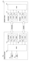
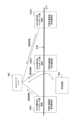
- FIG. 1 is a diagram showing the configuration of a communication device according to an embodiment.
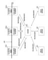
- FIG. 2 is a diagram illustrating an application example of a communication device according to an embodiment.
- FIG. 3 is a diagram illustrating an example of an operation scenario of the communication device according to the first embodiment.
- FIG. 3 is a diagram showing the content (format) of a sound wave signal transmitted and received in an example operation scenario according to the first embodiment.
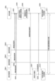
- FIG. 3 is a diagram illustrating an example of the operation flow of the communication device according to the first embodiment. It is a figure which shows the example of the operation
- FIG. 1 is a diagram showing the configuration of a communication device according to an embodiment.
- FIG. 2 is a diagram illustrating an application example of a communication device according to an embodiment.
- FIG. 3 is a diagram illustrating an example of an operation scenario of the communication device according to the first embodiment.
- FIG. 3 is a diagram showing the
- FIG. 7 is a diagram illustrating an example of an operation flow of a communication device according to a first modification of the first embodiment. It is a figure which shows the example of the operation
- FIG. 7 is a diagram illustrating the contents (format) of a sound wave signal transmitted and received in an example operation scenario according to a second modification of the first embodiment.
- FIG. 7 is a diagram illustrating an example of the operation flow of the communication device according to a second modification of the first embodiment. It is a figure which shows the example of the operation
- FIG. 7 is a diagram illustrating an example of the operation flow of the communication device according to a third modification of the first embodiment.
- FIG. 7 is a diagram illustrating an example of an operation scenario of a communication device according to a second embodiment.
- FIG. 6 is a diagram illustrating the contents (format) of a sound wave signal transmitted and received in an example operation scenario according to the second embodiment.
- FIG. 7 is a diagram illustrating an example of an operation flow of a communication device according to a second embodiment. It is a figure which shows an example of the content (format) of the notification sound wave signal based on 3rd Embodiment.
- FIG. 7 is a diagram illustrating an example of an operation scenario of a communication device according to a third embodiment.
- FIG. 7 is a diagram illustrating an example of an operation scenario of a communication device according to a first modification of the third embodiment.
- FIG. 7 is a diagram illustrating an example of an operation scenario of a communication device according to a second modification of the third embodiment.
- Sound waves have a longer communicable distance underwater than visible light (that is, the amount of attenuation in water is smaller), and have weaker directionality than visible light, so they are useful for determining the direction of the communication partner. It is suitable as a transmission medium.
- a sonar device like the communication device described in Patent Document 1, it is possible to detect an object by emitting sound waves and capturing the reflected waves.
- the present disclosure aims to facilitate the establishment of a visible light communication connection.
- the communication device according to the first embodiment is a device that performs underwater visible light communication with a target communication device (that is, a communication partner).
- a target communication device that is, a communication partner
- Such communication devices may be referred to as underwater communication devices or underwater visible light communication devices.
- underwater communication is mainly assumed as underwater communication below, underwater communication may also be communication in a lake or a river.
- FIG. 1 is a diagram showing the configuration of a communication device 100 according to the first embodiment.
- the communication device 100 includes a visible light communication section 110, a sound wave communication section 120, and a control section 130.
- the visible light communication unit 110 transmits and receives visible light signals including communication data under the control of the control unit 130. In other words, the visible light communication unit 110 performs data communication with the target communication device using visible light communication.
- the visible light communication section 110 includes a light emitting section 111, a light receiving section 112, and a driving section 113.
- the light emitting section 111 includes at least one light emitting element.
- the light emitting element may be a laser diode (LD) or a light emitting diode (LED).
- the light emitting unit 111 converts the electrical signal (transmission signal) output by the control unit 130 for visible light communication into a visible light signal, and transmits the visible light signal to the target communication device.
- the light emitting unit 111 may include a plurality of light emitting elements arranged in various directions so that visible light signals can be transmitted in various directions (for example, in all directions of 360 degrees).
- the light emitting element is an LD and that underwater laser communication is performed as underwater visible light communication.
- the communicable distance when using an LED is about several tens of meters, and the communicable distance when using an LD is about 200 meters.
- visible light is highly directional, highly accurate optical axis alignment technology is required.
- visible light communication allows higher speed communication than sound wave communication, and allows for smaller size and lower power consumption than sound wave communication.
- the light receiving section 112 includes at least one light receiving element.
- the light receiving unit 112 receives a visible light signal from the target communication device, converts the received visible light signal into an electrical signal (received signal), and outputs the received signal to the control unit 130.
- the light receiving unit 112 may include a plurality of light receiving elements arranged in various directions so as to be able to receive visible light signals from various directions (for example, all directions of 360 degrees).
- the driving unit 113 controls the visible light communication direction (for example, the optical axis direction), which is the direction in which the visible light communication unit 110 (specifically, the light emitting unit 111) transmits the visible light signal.
- the light emitting section 111 is driven so as to be variable.
- the drive unit 113 may include an actuator for changing the direction of the light emitting unit 111.
- the drive unit 113 may include an actuator for changing the orientation of the light receiving unit 112.
- the actuator may change the orientation of the set of the light emitting section 111 and the light receiving section 112.
- the drive unit 113 may include a drive circuit that selectively drives some light emitting elements corresponding to a specific direction among a plurality of light emitting elements arranged in various directions.
- the sonic communication unit 120 transmits and receives a sonic signal containing information used to control establishment of a visible light communication connection under the control of the control unit 130. In other words, the sonic communication unit 120 performs communication for controlling the establishment of a visible light communication connection using sonic communication.
- the sonic communication section 120 includes a wave transmitting section 121 and a wave receiving section 122.
- the wave transmitting unit 121 includes at least one wave transmitter.
- the wave transmitting unit 121 converts the electric signal (transmission signal) outputted by the control unit 130 for sonic communication into a sonic signal, and transmits the sonic signal.
- the wave receiving unit 122 includes at least one wave receiver. The wave receiving unit 122 receives a sound wave signal, converts the received sound wave signal into an electrical signal (received signal), and outputs the received signal to the control unit 130.
- Sound waves have a longer communicable transmission distance underwater than visible light, that is, the amount of attenuation in water is small, but the communication speed is very slow compared to visible light communication. Sound waves (acoustic signals) have weaker directivity than visible light (visible light signals), and do not require highly accurate optical axis alignment like visible light communication. In other words, acoustic wave communication allows communication over a wider communication range than visible light communication. However, acoustic wave communication consumes more power than visible light communication.
- the control unit 130 controls the overall operation of the communication device 100.
- the control unit 130 controls the visible light communication unit 110 and the acoustic wave communication unit 120.
- Control unit 130 includes at least one processor and at least one memory.
- the memory stores programs executed by the processor and information used in processing by the processor.
- the processor may include a digital signal processor and a CPU (Central Processing Unit).
- the digital signal processor modulates, demodulates, encodes, and decodes digital signals.
- the CPU executes programs stored in memory to perform various processes.
- the sonic wave communication unit 120 receives a sonic wave signal that is transmitted from the target communication device or another communication device and includes information used to control the establishment of a visible light communication connection. receive.
- the control unit 130 performs control to establish a visible light communication connection with the target communication device based on information included in the sound wave signal received by the sound wave communication unit 120. This enables more advanced control than when using a sonar device, and facilitates the establishment of visible light communication connections.
- the sonic wave communication unit 120 may receive the sonic signal including the identifier of the target communication device. Thereby, the control unit 130 can identify the target communication device based on the identifier included in the received sound wave signal.
- the sonic wave communication unit 120 (wave transmitting unit 121) may transmit a sonic signal including the identifier of the communication device 100. Thereby, another communication device that has received the sound wave signal can identify the communication device 100 based on the identifier included in the received sound wave signal.
- the control unit 130 acquires the position of the target communication device through sonic communication using the sonic communication unit 120. Based on the position of the target communication device and the position of the communication device 100 (i.e., self-position), the control unit 130 controls the visible light communication unit 110 (for example, the drive unit) so that the visible light communication direction is directed toward the target communication device. 113). Thereby, it is possible to appropriately direct the visible light communication direction (for example, the optical axis direction) toward the target communication device.
- the "position" is a three-dimensional position, and may be, for example, a position on the reference point coordinates. Alternatively, the "position" may be an absolute position consisting of latitude, longitude, and altitude.
- the sonic communication unit 120 receives a sonic signal including position information indicating the position of the target communication device.
- the control unit 130 acquires the position of the target communication device based on the position information included in the received sonic signal. Thereby, the control unit 130 can appropriately acquire the position of the target communication device.
- the sonic wave communication unit 120 receives a sonic wave signal including position information indicating the position of the target communication device from the target communication device. Thereby, the control unit 130 can directly acquire the position of the target communication device from the target communication device.
- the control unit 130 may store the self-position in advance. good.
- the communication device 100 is capable of receiving satellite signals from positioning satellites
- the communication device 100 has a GNSS (Global Navigation Satellite System) receiver, and the control unit 130 determines its own position using GNSS positioning. may be obtained.
- GNSS Global Navigation Satellite System
- the control unit 130 may acquire its own position using acoustic wave communication.
- a self-location acquisition method is suitable as a self-location acquisition method for the communication device 100 that operates as a terminal device. For example, after transmitting a first sound wave signal (hereinafter referred to as a "query sound wave signal"), the sound wave communication unit 120 transmits a second sound wave signal (hereinafter referred to as a "response sound wave signal”) from each base station device that has received the query sound wave signal. ”) may be received.
- a first sound wave signal hereinafter referred to as a "query sound wave signal”
- a second sound wave signal hereinafter referred to as a "response sound wave signal”
- the control unit 130 acquires the position of the terminal device (self-position) based on the round-trip propagation time with each base station device determined in response to reception of the response sound wave signal. Specifically, the control unit 130 can obtain the distance between the terminal device and each base station device from the underwater sound wave propagation speed (average sound speed) and the round-trip propagation time. When the control unit 130 acquires each distance to three or more base station devices, it can acquire its own position on the reference coordinates with each base station device as a reference point.
- Such a self-position acquisition method is sometimes referred to as an LBL (Long Base Line) method or an SBL (Short Base Line) method.
- LBL Long Base Line
- SBL Short Base Line
- the sonic communication unit 120 (wave transmitting unit 121) transmits a sonic signal including position information indicating the position (self-position) of the communication device 100 to the target communication device. Thereby, the target communication device can directly acquire the position of the communication device 100 from the communication device 100.
- the control unit 130 obtains the distance between the target communication device and the communication device 100 based on the position of the target communication device and the position of the communication device 100.
- the control unit 130 may control the initial transmission power of the visible light signal in visible light communication based on the acquired distance. Thereby, the control unit 130 can appropriately control and set the initial transmission power of the visible light signal in visible light communication.
- the sonic communication unit 120 receives a sonic signal including position information from each candidate communication device.
- the control unit 130 may obtain the distance to each candidate communication device based on the position of each candidate communication device and the position of the communication device 100.
- the control unit 130 may select a target communication device from these candidate communication devices based on each acquired distance. For example, the control unit 130 may select the candidate communication device having the shortest distance from the communication device 100 as the target communication device, giving priority to the candidate communication device over other candidate communication devices. Thereby, the control unit 130 can appropriately select the target communication device from among the plurality of candidate communication devices.
- the sonic communication unit 120 may transmit a connection sonic signal for establishing a visible light communication connection to and/or receive from the target communication device.
- the control unit 130 controls the visible light communication unit 110 to perform underwater visible light communication with the target communication device. This makes it possible to explicitly establish a visible light communication connection and appropriately start visible light communication.
- FIG. 2 is a diagram showing an application example of the communication device 100 according to the first embodiment.
- underwater communication is performed between a terminal device and a base station device.
- a case may be assumed in which underwater communication is performed between terminal devices.
- a case may be assumed in which underwater communication is performed between base station devices.
- a pair of communication devices self communication device and target communication device
- a pair of communication devices self communication device and target communication device that perform underwater visible light communication are both base station devices.
- one communication device 100 that performs underwater visible light communication is a terminal device 100a
- the other communication device 100 that performs underwater visible light communication is a base station device 100b.
- the base station device 100b is the target communication device
- the terminal device 100a is the target communication device.
- the base station device 100b has a backhaul communication section 140.
- the backhaul communication unit 140 communicates with the network side (for example, on the ground or on a ship) by wire communication, radio wave communication, or visible light communication under the control of the control unit 130b.
- the backhaul communication unit 140 may be capable of inter-base station communication with other nearby base station devices.
- the base station device 100b may include a GNSS positioning unit 150 that acquires the position (self-position) of the base station device 100b by GNSS positioning.
- the GNSS positioning unit 150 uses, for example, GPS (Global Positioning System), GLONASS (Global Navigation Satellite System), IRNSS (Indian Region 1 Navigational Satellite System), COMPASS, and Galileo.
- GPS Global Positioning System
- GLONASS Global Navigation Satellite System
- IRNSS Indian Region 1 Navigational Satellite System
- COMPASS Galileo
- Galileo Galileo
- the control unit 130b may store the position (self-position) of the base station apparatus 100b in advance. In this case, the base station device 100b does not need to have the GNSS positioning section 150.
- the visible light communication unit 110a of the terminal device 100a and the visible light communication unit 110b of the base station device 100b perform visible light communication (specifically, underwater visible light communication) and transmit and receive visible light signals.
- the sonic communication unit 120a of the terminal device 100a and the sonic communication unit 120b of the base station device 100b perform sonic communication (specifically, underwater sonic communication) and transmit and receive sonic signals.
- the sonic communication unit 120b receives a sonic signal transmitted from the terminal device 100a (wave transmitting unit 121a) and including information used to control establishment of a visible light communication connection.
- the control unit 130b performs control to establish a visible light communication connection with the terminal device 100a based on information included in the sonic signal received by the sonic communication unit 120b. For example, the control unit 130b acquires the position of the terminal device 100a through sonic communication using the sonic communication unit 120b.
- the control unit 130b controls the visible light communication unit 110b (for example, driving 113b).
- the sonic communication unit 120b may transmit a sonic signal including the base station ID to the terminal device 100a.
- the sound wave communication unit 120b (wave receiving unit 122b) may receive a sound wave signal including the terminal ID from the terminal device 100a.
- the sonic communication unit 120b may transmit a sonic signal including base station position information indicating the position of the base station device to the terminal device 100a.
- the sonic wave communication unit 120b (wave receiving unit 122b) may receive a sonic wave signal including terminal position information indicating the position of the terminal device 100a from the terminal device 100a.
- the sonic wave communication unit 120b may transmit a connection sonic signal for establishing a visible light communication connection to the terminal device 100a and/or receive it from the terminal device 100a.
- the sonic communication unit 120b receives a connection request sonic signal from the terminal device 100a, and transmits an acknowledgment sonic signal (hereinafter referred to as "ACK sonic signal") indicating acceptance of the connection request to the terminal device 100a.
- ACK sonic signal acknowledgment sonic signal
- the control unit 130b obtains the distance between the terminal apparatus 100a and the base station apparatus 100b based on the position of the terminal apparatus 100a and the position (self-position) of the base station apparatus 100b. Good too.
- the control unit 130b may control the initial transmission power of the visible light signal in visible light communication based on the acquired distance.
- the sonic wave communication unit 120a receives a sonic wave signal transmitted from the base station device 100b (wave transmitting unit 121b) and including information used to control establishment of a visible light communication connection. do.
- the control unit 130a performs control to establish a visible light communication connection with the base station device 100b based on information included in the sonic signal received by the sonic communication unit 120a. For example, the control unit 130a acquires the position of the base station device 100b through sonic communication using the sonic communication unit 120a.
- the control unit 130a controls the visible light communication unit 110a (for example, The drive unit 113a) is controlled.
- the sonic wave communication unit 120a may transmit a sonic signal including an identifier of the terminal device 100a (hereinafter referred to as “terminal ID”) to the base station device 100b.
- the sonic wave communication unit 120a (wave receiving unit 122a) may receive a sonic signal including an identifier of the base station device 100b (hereinafter referred to as “base station ID”) from the base station device 100b.
- the sonic communication unit 120a may transmit a sonic signal including terminal location information indicating the location of the terminal device 100a to the base station device 100b.
- the sonic communication unit 120a (wave receiving unit 122a) may receive a sonic signal including base station position information indicating the position of the base station device 100b from the base station device 100b.
- the sonic wave communication unit 120a may transmit a connection sonic signal for establishing a visible light communication connection to and/or receive from the base station device 100b.
- the sonic communication unit 120a may transmit a connection request sonic signal to the base station device 100b, and may receive an ACK sonic signal from the base station device 100b.
- the control unit 130a may obtain the distance between the terminal device 100a and the base station device 100b based on the location of the terminal device 100a (self-location) and the location of the base station device 100b. good.
- the control unit 130a may control the initial transmission power of the visible light signal in visible light communication based on the acquired distance.
- the terminal device 100a may perform underwater visible light communication with a base station device 100b selected from a plurality of base station devices 100b (that is, a plurality of candidate communication devices) as a target communication device.
- the control unit 130a may perform control to select a target communication device from among the plurality of base station devices 100b based on information included in the sonic signal received by the sonic communication unit 120a. This makes it possible to perform underwater visible light communication with the optimal target communication device among the plurality of base station devices 100b.
- the control unit 130a may obtain the distance between the terminal device 100a and each base station device 100b based on the sound wave signal received by the sound wave communication unit 120a.
- the control unit 130a may select a target communication device from among the plurality of base station devices 100b based on the distance acquired for each base station device 100b. For example, the control unit 130a may preferentially select the base station device 100b having the shortest distance from the terminal device 100a as the target communication device.
- the sonic communication unit 120b may transmit a sonic signal including accommodability information indicating whether the terminal device 100a can be accommodated in the base station device 100b. For example, if the base station device 100b is capable of visible light communication with only one terminal device 100a at a certain time and the base station device 100b is performing visible light communication with the terminal device 100a, the sonic wave communication unit 120b , the base station device 100b transmits a sound wave signal including accommodability information indicating that the terminal device 100a cannot be newly accommodated.
- the sonic communication unit 120a receives a sonic signal including accommodation availability information from the base station device 100b.
- the control unit 130a may select a target communication device from among the plurality of base station devices 100b based on accommodation availability information included in the received sound wave signal. Specifically, the control unit 130a extracts a base station device 100b that can newly accommodate the terminal device 100a from among the plurality of base station devices 100b, and selects a target communication device from among the extracted base station devices 100b. Select.
- FIG. 3 is a diagram illustrating an example of an operation scenario of the communication device 100 according to the first embodiment.
- FIG. 4 is a diagram showing the contents (format) of the sound wave signals transmitted and received in this example operation scenario.
- each base station device 100b has a function as a transponder in LBL.
- each base station device 100b is fixed to a buoy, for example.
- the visible light communication unit 110b and the acoustic wave communication unit 120b are located underwater (below the water surface), and the GNSS positioning unit 150 and the backhaul communication unit 140 are located above the water (above the water surface).
- the terminal device 100a is underwater.
- the terminal device 100a transmits and receives positioning sound wave signals in the LBL to and from each base station device 100b. Specifically, the terminal device 100a acquires the round-trip propagation time with each base station device 100b by transmitting a question sound wave signal to each base station device 100b and receiving a response sound wave signal from each base station device 100b. do. Then, the terminal device 100a acquires its own position based on the acquired round-trip propagation time.
- the terminal device 100a receives broadcast sound wave signals from each base station device 100b.
- the broadcast sound wave signal is a sound wave signal that is periodically transmitted and includes information regarding the base station device 100b.
- the broadcast sound wave signal is a broadcast message that does not specify the destination of the broadcast sound wave signal.
- the broadcast sound wave signal includes information regarding the base station device 100b that is the transmission source of the broadcast sound wave signal, as shown in FIG.
- the broadcasting sound wave signal includes the base station ID of the base station device 100b that is the transmission source of the broadcasting sound wave signal, the base station location information of the base station device 100b, and the accommodability information of the base station device 100b. including.
- the base station apparatus 100b instead of including the accommodation availability information in the broadcast sound wave signal, only the base station apparatus 100b that can accommodate the terminal device 100a may transmit the broadcast sound wave signal.
- the terminal device 100a acquires the position of each base station device 100b by receiving the broadcast sound wave signal from each base station device 100b.
- the terminal device 100a selects the base station device 100b as the target communication device, and transmits and receives the connection sound wave signal to and from the base station device 100b (target communication device). For example, the terminal device 100a transmits a connection request sonic signal to the base station device 100b (target communication device), and receives an ACK sonic signal from the base station device 100b (target communication device).
- the connection request sonic signal includes the base station ID of the base station device 100b (i.e., the destination of the connection request sonic signal) selected by the terminal device 100a, and the terminal device 100a (i.e., the destination of the connection request sonic signal). , the transmission source of the connection request sound wave signal), and the terminal location information of the terminal device 100a.
- the ACK sound wave signal includes the base station ID of the base station device 100b that is the transmission source of the ACK sound wave signal, and the terminal ID of the terminal device 100a that is the destination of the ACK sound wave signal.
- the base station device 100b acquires the location of the terminal device 100a by receiving the connection request sonic signal.
- the terminal device 100a directs the visible light communication direction toward the base station device 100b based on the position of the base station device 100b (target communication device) and the position of the terminal device 100a (self-position). Controls the visible light communication unit 110a.
- the base station device 100b configures the visible light communication unit 110b so that the visible light communication direction is directed toward the terminal device 100a based on the position of the base station device 100b (self-position) and the position of the terminal device 100a. control.
- a visible light communication connection is established between the base station device 100b and the terminal device 100a. Once the visible light communication connection is established, the base station device 100b and the terminal device 100a transmit and receive communication data using visible light communication.
- the base station device 100b that has received the connection request sonic signal rejects the connection request, it may transmit a negative acknowledgment sonic signal (NACK) sonic signal instead of transmitting the ACK sonic signal.
- NACK negative acknowledgment sonic signal
- the base station device 100b may not transmit the ACK sound wave signal when rejecting the connection request.
- the terminal device 100a selects the base station device 100b with the second highest priority when receiving the NACK sonic signal or when a predetermined time has elapsed since the transmission of the connection request sonic signal (i.e., when it is considered as a timeout).
- a connection request sound wave signal may be transmitted to the selected base station device 100b.
- the positioning sound wave signal, the notification sound wave signal, and the connection sound wave signal may be multiplexed in a time division manner (TDM).
- TDM time division manner
- the positioning sound wave signal, the notification sound wave signal, and the connection sound wave signal may be multiplexed by frequency division (FDM).
- FDM frequency division
- CDM code division
- the broadcast sound wave signals of each base station device 100b may be multiplexed in a time division manner.
- the broadcast sound wave signal may be multiplexed by frequency division.
- the broadcast sound wave signal may be multiplexed by code division using a unique orthogonal code sequence of each communication device 100.
- FIG. 5 is a diagram showing an example of the operation flow of the communication device 100 according to the first embodiment. In this operational flow example, it is assumed that each base station apparatus 100b has acquired its own position in advance.
- step S101 the terminal device 100a transmits an interrogation sound wave signal to each base station device 100b.
- the terminal device 100a transmits an interrogation sound wave signal when the need for data communication arises, for example, when communication data (for example, sensing data) to be transmitted to the network side is generated in the terminal device 100a. Good too.
- step S102 the base station device 100b3 that has received the interrogation sound wave signal transmits a response sound wave signal to the terminal device 100a.
- step S103 the base station device 100b2 that has received the interrogation sound wave signal transmits a response sound wave signal to the terminal device 100a.
- step S104 the base station device 100b1 that has received the interrogation sound wave signal transmits a response sound wave signal to the terminal device 100a.
- each base station apparatus 100b functions as a transponder in LBL.
- step S105 the terminal device 100a acquires its own position using LBL based on the results of steps S101 to S104.
- step S106 the base station device 100b3 transmits a broadcast sound wave signal to the terminal device 100a.
- step S107 the base station device 100b2 transmits a broadcast sound wave signal to the terminal device 100a.
- step S108 the base station device 100b1 transmits a broadcast sound wave signal to the terminal device 100a.
- each base station device 100b may transmit the notification sound wave signal using reception of the interrogation sound wave signal from the terminal device 100a as a trigger. In this case, each base station device 100b may transmit the broadcast sound wave signal only once. Alternatively, each base station device 100b may periodically transmit the notification sound wave signal only within a certain period of time after receiving the interrogation sound wave signal. This makes it possible to reduce power consumption compared to the case where the notification sound wave signal is always periodically transmitted.
- the terminal device 100a acquires the position of each base station device 100b by receiving the broadcast sound wave signal from each base station device 100b.
- step S109 the terminal device 100a selects the base station device 100b to be the target communication device (ie, the connection request destination).
- the target communication device ie, the connection request destination.
- step S110 the terminal device 100a transmits a connection request sonic signal to the base station device 100b1.
- This connection request sound wave signal includes the base station ID of the base station device 100b1 as a destination, and also includes the terminal location information of the terminal device 100a.
- step S111 the base station device 100b1 transmits an ACK sound wave signal to the terminal device 100a.
- This ACK sound wave signal includes the terminal ID of the terminal device 100a as the destination.
- step S112 the terminal device 100a performs visible light communication so that the visible light communication direction is directed toward the base station device 100b1, based on the self-position acquired in step S105 and the position of the base station device 100b1 acquired in step S108. 110a.
- step S113 the base station device 100b1 configures the visible light communication unit to direct the visible light communication direction toward the terminal device 100a based on the self-position acquired in advance and the position of the terminal device 100a acquired in step S110. 110b.
- step S114 the base station device 100b1 and the terminal device 100a perform processing to establish a visible light communication connection.
- each of the base station device 100b1 and the terminal device 100a sets the initial transmission power of the visible light signal based on the distance between the base station device 100b1 and the terminal device 100a.
- the base station device 100b1 and the terminal device 100a transmit and receive communication data using visible light communication.
- the communication device 100 according to the first modified example of the first embodiment will be mainly described with respect to the differences from the above-described first embodiment.
- the LBL reference point exists outside the base station device 100b. That is, a positioning communication device serving as an LBL reference point is provided separately from the base station device 100b.
- the sonic wave communication unit 120 of the communication device 100 transmits an interrogation sonic signal to a plurality of positioning communication devices, and receives a response sonic signal from each positioning communication device that has received the interrogation sonic signal.
- the control unit 130 of the communication device 100 acquires its own position based on the round-trip propagation time with each positioning communication device 200 determined according to the reception of the response sound wave signal.
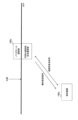
- FIG. 6 is a diagram illustrating an example of an operation scenario of the communication device 100 according to the first modification of the first embodiment.
- a plurality of positioning communication devices 200 are installed underwater.
- Each positioning communication device 200 has a sound wave communication unit and functions as a reference point and a transponder in the LBL.
- some of the plurality of positioning communication devices 200 may be integrated with any base station device 100b (see the first embodiment).
- the terminal device 100a transmits and receives positioning sound wave signals in LBL to and from each positioning communication device 200. Specifically, the terminal device 100a transmits an inquiry sound wave signal to each positioning communication device 200 and receives a response sound wave signal from each positioning communication device 200, thereby achieving round-trip propagation with each positioning communication device 200. Get the time. Then, the terminal device 100a acquires its own position based on the acquired round-trip propagation time.
- the base station device 100b may be movable. The base station device 100b may acquire its own position by transmitting and receiving positioning sound wave signals to and from each positioning communication device 200.
- FIG. 7 is a diagram illustrating an example of the operation flow of the communication device 100 according to the first modification of the first embodiment. In this operational flow example, it is assumed that each base station apparatus 100b has acquired its own position in advance.
- step S121 the terminal device 100a transmits an interrogation sound wave signal to each positioning communication device 200.
- each positioning communication device 200 that has received the interrogation sound wave signal transmits a response sound wave signal to the terminal device 100a.
- step S123 the terminal device 100a acquires its own position using LBL based on the results of steps S121 and S122.
- the communication device 100 according to the second modified example of the first embodiment will be mainly described with respect to the differences from the above-described first embodiment.
- a location management communication device that manages the location of each communication device 100 is provided.
- the sonic wave communication unit 120 of the communication device 100 receives a sonic signal including position information indicating the position of the target communication device from the position management communication device.
- FIG. 8 is a diagram illustrating an example of an operation scenario of the communication device 100 according to the second modification of the first embodiment.
- FIG. 9 is a diagram showing the contents (format) of the sound wave signals transmitted and received in this example operation scenario.
- a plurality of positioning communication devices 200 and a position management communication device 300 are installed underwater.
- the positioning communication device 200 is the same as the first modification example described above.
- the position management communication device 300 has a sonic communication unit and performs sonic communication with the terminal device 100a and the base station device 100b.
- the terminal device 100a acquires its own position using the positioning communication device 200, similarly to the first modification example described above.
- the base station device 100b may also acquire its own position using the positioning communication device 200. Therefore, the base station device 100b may be movable.
- the terminal device 100a transmits a registration sound wave signal including terminal location information to the location management communication device 300.
- the registration sound wave signal from the terminal device 100a includes the terminal ID of the terminal device 100a and the terminal location information of the terminal device 100a, as shown in FIG.
- the registration sound wave signal may further include the ID of the location management communication device 300 as a destination.
- Each base station device 100b may transmit a registration sound wave signal including base station location information to the location management communication device 300.
- the registration sound wave signal from the base station device 100b includes the base station ID of the base station device 100b, the base station location information of the base station device 100b, and the base station location information of the base station device 100b. This includes accommodability information.
- the location management communication device 300 may acquire the location of each base station device 100b in advance. In that case, the location management communication device 300 may not need the registration sound wave signal from the base station device 100b.
- the base station device 100b may transmit a registration sound wave signal that does not include the base station location information but includes the base station ID and accommodability information.
- the location management communication device 300 transmits a notification sound wave signal including the location information of each communication device 100 based on the information of each communication device 100 that it manages.
- the broadcasting sound wave signal according to this modification example includes the base station ID, base station location information, and accommodability information of each base station device 100b, and the terminal ID and terminal location information of the terminal device 100a. including.
- the terminal device 100a obtains the location (and whether the terminal can accommodate the terminal) of each base station device 100b by receiving the broadcast sound wave signal from the location management communication device 300.
- Each base station device 100b acquires the location of the terminal device 100a by receiving the broadcast sound wave signal from the location management communication device 300. Therefore, in this modified example, the connection request sound wave signal transmitted by the terminal device 100a does not need to include the terminal location information of the terminal device 100a.
- the positioning sound wave signal, the registration sound wave signal, the notification sound wave signal, and the connection sound wave signal may be multiplexed in a time division manner (TDM) in the sound wave communication area.
- the positioning sound wave signal, the registration sound wave signal, the notification sound wave signal, and the connection sound wave signal may be multiplexed by frequency division (FDM).
- the positioning sound wave signal, the registration sound wave signal, the notification sound wave signal, and the connection sound wave signal may be multiplexed by code division (CDM).
- the registration sound wave signals of each communication device 100 may be multiplexed in a time division manner.
- the registration sound wave signals of each communication device 100 may be multiplexed by frequency division.
- the registration sound wave signals of each communication device 100 may be multiplexed by code division using an orthogonal code sequence specific to each communication device 100.
- each base station apparatus 100b when the state of whether it can accommodate a terminal changes, specifically becomes unable to accommodate a new terminal apparatus 100a or becomes able to accommodate a new terminal apparatus 100a.
- a registration sound wave signal including accommodability information indicating the changed terminal accommodability state may be transmitted to the location management communication device 300.
- Each base station device 100b may transmit a registration sound wave signal to the location management communication device 300 when determining that its own location has been changed.
- FIG. 10 is a diagram showing an example of the operation flow of the communication device 100 according to the second modified example of the first embodiment. In this operational flow example, it is assumed that each base station apparatus 100b has acquired its own position in advance.
- step S130 the terminal device 100a acquires its own position in the same manner as in the first modification example described above.
- step S131 the base station device 100b1 transmits a registration sonic signal to the location management communication device 300.
- step S132 the base station device 100b2 transmits a registration sonic signal to the location management communication device 300.
- step S133 the base station device 100b3 transmits the registration sonic signal to the location management communication device 300.
- the location management communication device 300 acquires the location of each base station device 100b and/or whether or not a terminal can be accommodated based on the registration sound wave signal from each base station device 100b.
- step S134 the terminal device 100a transmits the registration sound wave signal to the location management communication device 300.
- the location management communication device 300 acquires the location of the terminal device 100a based on the registration sound wave signal from the terminal device 100a.
- step S135 the location management communication device 300 transmits a notification sound wave signal.
- the terminal device 100a acquires the position of each base station device 100b by receiving the broadcast sound wave signal.
- Each base station device 100b acquires the position of the terminal device 100a by receiving the broadcast sound wave signal.
- connection request sound wave signal transmitted from the terminal device 100a to the base station device 100b1 in step S110 does not include the location information of the terminal device 100a, but includes the identifier (destination) of the base station device 100b1 and the identifier (destination) of the terminal device 100a. (sending source).
- the communication device 100 according to the third modified example of the first embodiment will be mainly described with respect to the differences from the above-described first embodiment.
- the sonic communication unit 120a of the terminal device 100a receives the positioning reference signal transmitted from each base station device 100b in synchronization between the base station devices 100b as a sonic signal.
- the control unit 130a of the terminal device 100a acquires the position of the terminal device 100a based on the received positioning reference signal.
- FIG. 11 is a diagram illustrating an example of an operation scenario of the communication device 100 according to the second modification of the first embodiment.
- each base station device 100b transmits positioning reference signals as sound wave signals in synchronization with each other.
- the terminal device 100a can acquire its own position on the reference point coordinates with each base station device 100b as the reference point, based on the arrival time difference of each positioning reference signal. Therefore, it is not necessary to transmit and receive positioning sound wave signals (query sound wave signal and response sound wave signal) in the LBL as described above.
- each base station device 100b may always transmit the positioning reference signal separately from the broadcast sound wave signal.
- Each base station device 100b may configure a positioning reference signal using an orthogonal sequence using its own base station ID as a seed. Thereby, the terminal device 100a can acquire the base station ID based on the positioning reference signal, and therefore can associate the positioning reference signal and the broadcast sound wave signal based on the base station ID.
- the positioning reference signal, the notification sound wave signal, and the connection sound wave signal may be time-division multiplexed (TDM) in the sound wave communication area.
- TDM time-division multiplexed
- the positioning sound wave signal, the registration sound wave signal, the notification sound wave signal, and the connection sound wave signal may be multiplexed by frequency division (FDM).
- FDM frequency division
- the positioning sound wave signal, the registration sound wave signal, the notification sound wave signal, and the connection sound wave signal may be multiplexed by code division (CDM).
- the positioning reference signal may be shared with the notification sound wave signal.
- each base station device 100b may simultaneously transmit broadcast sound wave signals using orthogonal code sequences.
- FIG. 12 is a diagram illustrating an example of the operation flow of the communication device 100 according to the third modified example of the first embodiment. In this operational flow example, it is assumed that each base station apparatus 100b has acquired its own position in advance.
- the base station devices 100b1 to 100b3 transmit the positioning reference signal as a sound wave signal.
- step S144 the terminal device 100a acquires its own position based on the positioning reference signals received from the base station devices 100b1 to 100b3.
- the visible light communication direction was controlled by acquiring the position of each communication device 100, but in the second embodiment, instead of acquiring the position of each communication device 100, The visible light communication direction is controlled by acquiring the arrival direction of the acoustic wave signal from the target communication device.
- the sonic communication unit 120 receives the sonic signal transmitted from the target communication device.
- the control unit 130 estimates the arrival direction of the sound wave signal based on the sound wave signal received by the sound wave communication unit 120. Then, the control unit 130 controls the visible light communication unit 110 so that the visible light communication direction (for example, the optical axis direction) becomes the arrival direction. Thereby, it is possible to appropriately direct the visible light communication direction toward the target communication device.
- the wave receiving unit 122 of the sonic wave communication unit 120 of the communication device 100 includes a wave receiver array consisting of wave receivers installed at intervals comparable to the wavelength of the sound wave.
- the control unit 130 obtains the angle of arrival (direction of arrival) of the sound wave signal as a phase difference between the receivers.
- a method using such a method is also called a USBL (Ultra Short Base Line) method.
- the control unit 130 of the communication device 100 performs the following based on the attenuation amount calculated from the transmission power of the sonic signal in the target communication device and the reception power of the sonic signal received by the sonic communication unit 120.
- the distance between the target communication device and the communication device 100 may be acquired.
- the control unit 130 may control the initial transmission power of the visible light signal in visible light communication based on the acquired distance.
- the sonic wave communication unit 120 of the communication device 100 may receive a sonic signal from each of the plurality of candidate communication devices.
- the control unit 130 may acquire the distance between each candidate communication device and the communication device 100 based on the amount of attenuation, and select a target communication device from among the plurality of candidate communication devices based on the acquired distance. good.
- FIG. 13 is a diagram illustrating an example of an operation scenario of the communication device 100 according to the second embodiment.
- FIG. 14 is a diagram showing the contents (format) of the sound wave signals transmitted and received in this example operation scenario.
- the base station device 100b is on the water surface. Specifically, in the base station device 100b, the visible light communication unit 110b and the acoustic wave communication unit 120b are located underwater (below the water surface), and the backhaul communication unit 140 is located above the water (above the water surface). The base station device 100b does not need to have the GNSS positioning unit 150. In the second embodiment, the base station device 100b may be movable because the visible light communication direction is controlled by acquiring the arrival direction of the acoustic wave signal. The terminal device 100a is underwater.
- the base station device 100b transmits a broadcast sound wave signal.
- the broadcasting sound wave signal includes the base station ID of the base station device 100b, accommodating information of the base station device 100b, and transmission power indicating the transmission power of the broadcasting sound wave signal. power information. However, if the transmission power of the broadcast sound wave signal is known (fixed), the broadcast sound wave signal does not need to include transmission power information.
- the terminal device 100a receives the broadcast sound wave signal and acquires the direction of arrival of the broadcast sound wave signal. Furthermore, the terminal device 100a obtains the distance between the base station device 100b and the terminal device 100a based on the attenuation amount calculated from the transmission power of the broadcast sound wave signal and the reception power of the broadcast sound wave signal.
- the terminal device 100a may receive broadcast sound wave signals from each of the plurality of base station devices 100b.
- the terminal device 100a may acquire the distance between each base station device 100b and the terminal device 100a, and select a target communication device from among the plurality of base station devices 100b based on the acquired distance.
- the terminal device 100a transmits and receives a connection sound wave signal to and from the base station device 100b (target communication device). For example, the terminal device 100a transmits a connection request sonic signal to the base station device 100b, and receives an ACK sonic signal from the base station device 100b.
- the connection request sonic signal includes the base station ID of the base station device 100b (i.e., the destination of the connection request sonic signal) selected by the terminal device 100a, and the terminal device 100a (i.e., the destination of the connection request sonic signal), as shown in FIG. , the transmission source of the connection request sonic signal), and distance information indicating the distance between the base station device 100b and the terminal device 100a.
- the distance information is used by the base station device 100b to control the initial transmission power of the visible light signal.
- the ACK sound wave signal includes the base station ID of the base station device 100b that is the transmission source of the ACK sound wave signal, and the terminal ID of the terminal device 100a that is the destination of the ACK sound wave signal.
- the base station device 100b receives the connection request sonic signal from the terminal device 100a, and acquires the arrival direction of the broadcast sonic signal. Furthermore, the base station device 100b obtains the distance between the base station device 100b and the terminal device 100a based on the distance information included in the connection request sonic signal.
- the terminal device 100a controls the visible light communication unit 110a so that the visible light communication direction becomes the direction of arrival based on the estimated direction of arrival of the broadcast sound wave signal.
- the base station device 100b controls the visible light communication unit 110b so that the visible light communication direction becomes the direction of arrival based on the estimated direction of arrival of the connection request sound wave signal.
- a visible light communication connection is established between the base station device 100b and the terminal device 100a. Once the visible light communication connection is established, the base station device 100b and the terminal device 100a transmit and receive communication data using visible light communication.
- the broadcast sound wave signal and the connection sound wave signal may be multiplexed in a time division manner (TDM).
- TDM time division manner
- FDM frequency division
- CDM code division
- the broadcast sound wave signals of each base station device 100b may be multiplexed in a time division manner.
- the broadcast sound wave signals of each base station device 100b may be multiplexed by frequency division.
- the broadcast sound wave signals of each base station apparatus 100b may be multiplexed by code division using an orthogonal code sequence specific to each base station apparatus 100b.
- FIG. 15 is a diagram showing an example of the operation flow of the communication device 100 according to the second embodiment.
- the terminal device 100a receives broadcast sound wave signals from three base station devices 100b.
- step S201 the base station device 100b3 transmits a broadcast sound wave signal to the terminal device 100a.
- step S202 the base station device 100b2 transmits a broadcast sound wave signal to the terminal device 100a.
- step S203 the base station device 100b1 transmits a broadcast sound wave signal to the terminal device 100a.
- the terminal device 100a estimates the arrival direction of the broadcast sound wave signal from each base station device 100b. Furthermore, the terminal device 100a acquires (estimates) the distance between the terminal device 100a and each base station device 100b based on the attenuation amount of the broadcast sound wave signal from each base station device 100b. Note that the terminal device 100a receives the broadcast sound wave signal from each base station device 100b multiple times, and estimates the direction of arrival for each base station device 100b multiple times, thereby performing processing for increasing the accuracy of estimating the direction of arrival. You may go.
- the terminal device 100a selects the base station device 100b to be the target communication device (ie, the connection request destination).
- the terminal device 100a may preferentially select the base station device 100b having the shortest distance from the terminal device 100a as the target communication device.
- the terminal device 100a may extract a base station device 100b that can accommodate the terminal device 100a based on the broadcast sound wave signal from each base station device 100b, and select the extracted base station device 100b as a target communication device. good.
- the terminal device 100a selects the base station device 100b1 as the target communication device.
- step S206 the terminal device 100a transmits a connection request sonic signal to the base station device 100b1.
- This connection request sound wave signal includes the base station ID of the base station device 100b1 as a destination, and also includes distance information indicating the distance between the base station device 100b1 and the terminal device 100a.
- step S207 the base station device 100b1 receives the connection request sonic signal and estimates the arrival direction of the connection request sonic signal.
- step S208 the base station device 100b1 transmits an ACK sound wave signal to the terminal device 100a.
- This ACK sound wave signal includes the terminal ID of the terminal device 100a as the destination.
- the terminal device 100a may estimate the direction of arrival of the ACK sound wave signal, taking into consideration the possibility that the base station device 100b1 moves. If the direction of arrival of the ACK sound wave signal has changed from the direction of arrival estimated in step S204, the terminal device 100a may control the visible light communication direction using the direction of arrival of the ACK sound wave signal.
- step S209 the terminal device 100a controls the visible light communication unit 110a based on the estimated direction of arrival so that the visible light communication direction becomes the direction of arrival.
- step S210 the base station device 100b1 controls the visible light communication unit 110b so that the visible light communication direction becomes the direction of arrival based on the direction of arrival estimated in step S207.
- step S211 the base station device 100b1 and the terminal device 100a perform processing to establish a visible light communication connection.
- each of the base station device 100b1 and the terminal device 100a sets the initial transmission power of the visible light signal based on the distance between the base station device 100b1 and the terminal device 100a.
- the base station device 100b1 and the terminal device 100a transmit and receive communication data using visible light communication.
- the control unit 130 of the communication device 100 may calculate an evaluation value indicating the estimation accuracy of the direction of arrival.
- the control unit 130 may also control a movable range (also referred to as a "perturbation range") when adjusting the visible light communication direction (optical axis) in visible light communication based on the calculated evaluation value. good.
- the evaluation value indicating the estimation accuracy of the direction of arrival may be, for example, a variance value and an amount of change in direction when direction estimation using acoustic wave communication is performed multiple times. Specifically, when the variance is small, the control unit 130 may determine that the accuracy of narrowing down the direction of arrival is high and narrow the perturbation range.
- control unit 130 may estimate the moving direction and speed of the target communication device from the change in direction, and if the moving speed is fast, may extend the perturbation range in the moving direction of the target communication device. Further, the control unit 130 may re-estimate the direction of arrival (repeatedly) if the evaluation value indicating the accuracy of estimating the direction of arrival is worse than the threshold value.
- the terminal device 100a selects the target communication device (connection request destination) based on the distance to the base station device 100b and/or whether the base station device 100b can accommodate the terminal. .
- the base station apparatus 100b selected by such a selection method is not necessarily the optimal base station apparatus 100b from the viewpoint of the propagation environment in visible light communication. Since the terminal device 100a does not know the optical propagation environment with the selected base station device 100b until it establishes a visible light communication connection with the selected base station device 100b, the optical propagation environment with the selected base station device 100b is poor. obtain.
- the terminal device 100a selects a connection request destination in consideration of the propagation environment. Select base station device 100b. Note that the third embodiment can be used in combination with the first and second embodiments described above.
- the sonic communication unit 120a of the terminal device 100a receives a sonic signal that includes propagation environment information indicating a propagation environment that affects underwater visible light communication.
- the propagation environment information indicates at least one of turbidity and sunlight noise as the propagation environment.
- the control unit 130a of the terminal device 100a selects the base station device 100b to which the connection is requested from among the plurality of base station devices 100b based on the propagation environment information included in the received sound wave signal. This makes it possible to select the optimal base station apparatus 100b from the viewpoint of the propagation environment in visible light communication.
- the operation after the terminal device 100a selects the base station device 100b to which a connection request is made is the same as in the first and second embodiments described above.
- FIG. 16 is a diagram showing an example of the content (format) of the notification sound wave signal according to the third embodiment.
- the broadcasting sound wave signal according to the third embodiment includes the base station ID of the base station device 100b, the base station position information of the base station device 100b, the accommodability information of the base station device 100b, and the information about the base station device 100b. and propagation environment information indicating the propagation environment.
- the propagation environment information includes at least one of a value indicating turbidity and a value indicating sunlight noise. These values may be numerical values corresponding to measured values. Alternatively, these values may be index values such as high, medium, and low.
- the broadcasting sound wave signal may include transmission power information indicating the transmission power of the broadcasting sound wave signal instead of the base station location information.
- the terminal device 100a acquires (estimates) the propagation environment of each base station device 100b by receiving broadcasting sound wave signals as shown in FIG. 16 for the plurality of base station devices 100b, and issues a connection request based on the acquired propagation environment.
- the previous base station device 100b is selected.
- the broadcast sound wave signal may be transmitted from the base station device 100b or from the location management communication device 300. In the latter case, each base station device 100b may register its own propagation environment information in the location management communication device 300 using a registration sound wave signal.
- the broadcasting sound wave signal transmitted from the location management communication device 300 may include propagation environment information of each of the plurality of base station devices 100b (see FIG. 9).
- FIG. 17 is a diagram illustrating an example of an operation scenario of the communication device 100 according to the third embodiment.
- base station devices 100b1 and 100b2 are underwater (specifically, on the bottom of the water), and base station device 100b3 is on the water surface.
- the base station device 100b1 is located closer to the water surface than the base station device 100b2.
- the terminal device 100a is underwater.
- each base station device 100b has a turbidity sensor and a sunlight noise sensor (for example, an illuminance sensor for measuring environmental light that becomes noise).
- each base station device 100b is in a state where it can newly accommodate the terminal device 100a.
- the sensor is not limited to a sunlight noise sensor but may be any sensor that measures environmental light that becomes noise.
- the base station device 100b1 transmits a notification sound wave signal including propagation environment information indicating the turbidity and sunlight noise measured by itself.
- the measured turbidity is “medium” and the measured solar noise is “medium”.
- the base station device 100b2 also transmits a notification sound wave signal including propagation environment information indicating turbidity and sunlight noise measured by the base station device 100b2.
- the measured turbidity is "high” and the measured solar noise is “low”.
- the base station device 100b3 transmits a notification sound wave signal including propagation environment information indicating turbidity and sunlight noise measured by the base station device 100b3.
- the measured turbidity is "low” and the measured solar noise is “high.”
- the terminal device 100a that has received the broadcasting sound wave signal from each base station device 100b acquires the propagation environment of each base station device 100b based on the propagation environment information included in each broadcasting sound wave signal, and based on the acquired propagation environment.
- the base station device 100b to which the connection is requested is selected.
- the terminal device 100a determines that the base station device 100b2 whose turbidity is “high” and the base station device 100b3 whose sunlight noise is “high” are inappropriate as connection request destinations, and The station device 100b3 is selected as the connection request destination.
- the terminal device 100a may select a base station device 100b to which a connection is requested based on the distance between each base station device 100b and the terminal device 100a, in addition to the propagation environment of each base station device 100b.
- the distance acquisition method may be a distance acquisition method based on position as in the first embodiment.
- the method for obtaining the distance may be a distance obtaining method based on the amount of attenuation as in the second embodiment.
- the terminal apparatus 100a is connected to the base station with the smaller solar noise of the two base station apparatuses 100b.
- the station device 100b may also be selected.
- Condition 1 The distance (A) between the terminal device 100a and the base station device 100b (A) is larger than the distance (B) between the terminal device 100a and the base station device 100b (B), but the distance ( The difference between A) and distance (B) is within the threshold.
- Condition 2 The terminal device 100a can communicate with the base station device 100b (A) at the maximum transmission power or less.
- Condition 3 Regarding the base station device 100b (A) The propagation environment (turbidity and amount of sunlight noise) of the base station device 100b (B) is better than the propagation environment (turbidity and amount of sunlight noise), all conditions 1 to 3 are satisfied. In this case, the terminal device 100a may select the base station device 100b(A) which is far away from the base station device 100b(B), instead of the base station device 100b(B) which is close to the base station device 100b(B).
- the terminal device 100a may select the color of visible light used for visible light communication based on the chlorophyll concentration. This allows the terminal device 100a to select the optimal color.
- each base station device 100b measures the propagation environment
- another communication device for example, the positioning communication device 200 (see FIG. 6) and/or the location management communication device 300 ( (see FIG. 8) may also have a turbidity sensor and a sunlight noise sensor.
- the other communication device may notify the terminal device 100a and/or the base station device 100b of the measured propagation environment by sonic communication.
- the sonic communication unit 120a of the terminal device 100a receives a sonic signal including recommended base station information indicating at least one base station device 100b selected on the network side.
- the control unit 130a of the terminal device 100a selects the base station device 100b to which the connection is requested based on the recommended base station information.
- FIG. 18 is a diagram illustrating an example of an operation scenario of the communication device 100 according to the first modification of the third embodiment.
- each base station device 100b notifies the network node 400 of the measured propagation environment (turbidity/sunlight noise information).
- Network node 400 may be a node provided on a communication network.
- the network node 400 may be a node attached to any base station device 100b.
- the propagation environment information notified from each base station device 100b to the network node 400 may be a numerical value corresponding to a measured value.
- the propagation environment information may be an index value such as high, medium, or low.
- the timing of the notification may be the timing when the turbidity/sunlight noise measured by each base station device 100b changes or the notification may be made at regular timing.
- the network node 400 generates or updates an environment information map based on the propagation environment information from each base station device 100b.
- the environmental information map may be map information indicating a correspondence relationship between a position and a propagation environment.
- the terminal device 100a notifies the network node 400 of its own location information and connection request via any base station device 100b within the range where it can communicate with sound waves.
- the network node 400 notifies the terminal device 100a of the base station device 100b that is preferable for the terminal device 100a via the base station device 100b. Only one base station apparatus 100b may be notified to the terminal apparatus 100a, or a list may be provided in a preferable order from the top.
- the base station apparatuses 100b included in the list may be a list that does not take into consideration whether or not terminals can be accommodated, or may be a list that excludes base station apparatuses 100b that cannot accommodate terminals.
- the terminal device 100a determines whether the terminal can be accommodated based on the broadcast sound wave signal from each base station device 100b.
- each base station device 100b notifies the network node 400 of the change (state after change) in response to a change in the terminal accommodating state. It's okay. This notification may be performed together with the environmental information notification or alone. Further, each base station device 100b may be notified in response to a request from the network node 400.
- FIG. 19 is a diagram illustrating an example of an operation scenario of the communication device 100 according to the second modification of the third embodiment.
- a large number of fixed optical sensors 500 having an optical communication function are arranged.
- each base station device 100b acquires the light propagation state between itself and a known fixed point (photosensor 500) by regularly performing visible light communication with the optical sensor 500 at an arbitrary timing. do.
- the light propagation state may be, for example, information indicating the amount of attenuation of a visible light signal.
- the base station device 100b that is in optical communication with the terminal device 100a requests location information from the terminal device 100a at an arbitrary timing, acquires the location information and optical propagation state of the terminal device 100a, and transmits the acquired information.
- the network node 400 may also be notified.
- the terminal device 100a may notify the network node 400 of its own location information and optical propagation state. This notification may be made via visible light communication via the connected base station device 100b, or may be made via sonic communication via any base station device 100b. A timestamp indicating the time when the optical propagation state was acquired may be added to these notifications.
- each base station device 100b notifies the network node 400 that manages the optical propagation state of the optical propagation state and the corresponding position at an arbitrary timing.
- the network node 400 generates or updates a light propagation state map.
- the light propagation state map may be map information indicating a correspondence relationship between a position and a light propagation state.
- the terminal device 100a notifies the network node 400 of its own location information and connection request via any base station device 100b within the range where it can communicate with sound waves.
- the network node 400 notifies the terminal device 100a of the base station device 100b that is preferable for the terminal device 100a via the base station device 100b.
- the above-mentioned operation flows are not limited to being implemented separately, but can be implemented by combining two or more operation flows. For example, some steps of one operation flow may be added to another operation flow, or some steps of one operation flow may be replaced with some steps of another operation flow. Further, the order of steps in each of the above-mentioned operation flows is an example, and the order of steps may be changed as appropriate.
- a program that causes a computer to execute each process performed by the communication device 100 may be provided.
- the program may be recorded on a computer readable medium.
- Computer-readable media allow programs to be installed on a computer.
- the computer-readable medium on which the program is recorded may be a non-transitory recording medium.
- the non-transitory recording medium is not particularly limited, and may be, for example, a recording medium such as a CD-ROM or a DVD-ROM.
- the circuits that execute each process performed by the communication device 100 may be integrated, and at least a portion of the communication device 100 may be configured as a semiconductor integrated circuit (chip set, SoC: System on a chip).
- the words “based on” and “in accordance with” do not mean “based solely on” or “in accordance with” unless expressly stated otherwise. Reference to “based on” means both “based solely on” and “based at least in part on.” Similarly, the phrase “in accordance with” means both “in accordance with” and “in accordance with, at least in part.” Furthermore, “obtain/acquire” may mean obtaining information from among stored information, or may mean obtaining information from among information received from other nodes. Alternatively, it may mean obtaining the information by generating the information.
- the terms “include”, “comprise”, and variations thereof do not mean to include only the listed items, but may include only the listed items or in addition to the listed items.
- any reference to elements using the designations "first,” “second,” etc. used in this disclosure does not generally limit the amount or order of those elements. These designations may be used herein as a convenient way of distinguishing between two or more elements. Thus, reference to a first and second element does not imply that only two elements may be employed therein or that the first element must precede the second element in any way.
- articles are added by translation, for example, a, an, and the in English, these articles are used in the plural unless the context clearly indicates otherwise. shall include things.
- a communication device that performs underwater visible light communication with a target communication device, a visible light communication unit that transmits and receives visible light signals including communication data; a sonic communication unit that receives a sonic signal that is transmitted from the target communication device or another communication device and includes information used to control establishment of a visible light communication connection;
- a communication device comprising: a control unit that performs control to establish the visible light communication connection with the target communication device based on the information included in the received sound wave signal.
- the visible light communication direction in which the visible light communication unit transmits the visible light signal is variable,
- the control unit includes: acquiring the position of the target communication device by sonic communication using the sonic communication unit; According to (1) or (2) above, the visible light communication unit is controlled so that the visible light communication direction is directed toward the target communication device based on the position of the target communication device and the position of the communication device. communication equipment.
- the sonic wave communication unit receives the sonic signal including position information indicating the position of the target communication device as the information, The communication device according to any one of (1) to (3) above, wherein the control unit acquires the position of the target communication device based on the position information included in the sound wave signal.
- the communication device is a terminal device that performs the underwater visible light communication using a base station device selected from a plurality of base station devices as the target communication device, The communication device according to any one of (1) to (6) above, wherein the control unit further acquires the position of the terminal device through the sonic wave communication.
- the sonic wave communication unit includes: transmitting a first sound wave signal; receiving a second sound wave signal from each base station device that received the first sound wave signal; The control unit acquires the position of the terminal device based on the round-trip propagation time with each base station device determined in response to reception of the second sound wave signal.
- the sonic wave communication unit includes: transmitting a first sound wave signal to a plurality of positioning communication devices different from the base station device; receiving a second sound wave signal from each positioning communication device that received the first sound wave signal; The control unit acquires the position of the terminal device based on the round-trip propagation time with each of the positioning communication devices determined in response to reception of the second sound wave signal.
- the communication device described in Crab The communication device described in Crab.
- the sonic wave communication unit receives, as the sonic signal, a positioning reference signal transmitted from each base station device in synchronization between the base station devices, The communication device according to any one of (1) to (9) above, wherein the control unit acquires the position of the terminal device based on the received positioning reference signal.
- the control unit includes: obtaining the distance between the communication device and the communication device based on the location of the target communication device and the location of the communication device; The communication device according to any one of (1) to (10), wherein the initial transmission power of the visible light signal in the underwater visible light communication is controlled based on the acquired distance.
- the visible light communication direction in which the visible light communication unit transmits the visible light signal is variable,
- the sound wave communication unit receives the sound wave signal transmitted from the target communication device,
- the control unit includes: Estimating the arrival direction of the sound wave signal based on the sound wave signal received by the sound wave communication unit,
- the communication device according to any one of (1) to (11) above, wherein the visible light communication unit is controlled so that the visible light communication direction is the arrival direction.
- the control unit includes: between the target communication device and the communication device based on the amount of attenuation calculated from the transmission power of the sonic signal in the target communication device and the reception power of the sonic signal received by the sonic communication unit. get the distance,
- the communication device according to any one of (1) to (12), wherein the initial transmission power of the visible light signal in the underwater visible light communication is controlled based on the acquired distance.
- the control unit includes: Calculating an evaluation value indicating the estimation accuracy of the direction of arrival, The communication device according to any one of (1) to (13) above, wherein a movable range when adjusting the visible light communication direction in the underwater visible light communication is controlled based on the calculated evaluation value.
- the sonic wave communication unit transmits a connection sonic signal for establishing the visible light communication connection to and/or receives from the target communication device,
- the control unit controls the visible light communication unit to perform the underwater visible light communication with the target communication device after the visible light communication connection is established.
- the communication device is a terminal device that performs the underwater visible light communication using a base station device selected from a plurality of base station devices as the target communication device,
- the control unit performs the control to select the target communication device from among the plurality of base station devices based on the information included in the sound wave signal, according to any one of (1) to (15) above. communication equipment.
- the control unit includes: Obtaining the distance between the communication device and each base station device based on the sound wave signal, The communication according to any one of (1) to (16) above, wherein the control is performed to select the target communication device from among the plurality of base station devices based on the distance acquired for each of the base station devices. Device.
- the sonic wave communication unit receives the sonic signal including accommodability information indicating whether or not the terminal device can be accommodated in the base station device as the information,
- the control unit performs the control to select the target communication device from among the plurality of base station devices based on the accommodation availability information included in the sound wave signal.
- the sonic wave communication unit receives the sonic signal including propagation environment information indicating a propagation environment that affects the underwater visible light communication with the base station device as the information,
- the propagation environment information indicates at least one of turbidity and sunlight noise as the propagation environment
- the control unit performs the control to select the target communication device from among the plurality of base station devices based on the propagation environment information included in the sound wave signal.
- the sonic wave communication unit receives the sonic signal including recommended base station information indicating at least one base station device selected by the network side from among the plurality of base station devices as the information,
- the control unit performs the control to select the target communication device from among the plurality of base station devices based on the recommended base station information included in the sound wave signal.
- a communication method used in a communication device that performs underwater visible light communication with a target communication device, receiving a sound wave signal transmitted from the target communication device or another communication device and including information used to control establishment of a visible light communication connection; Performing control for establishing the visible light communication connection with the target communication device based on the information included in the received sound wave signal;
- a communication method comprising: transmitting and receiving visible light signals containing communication data.
- Communication device 100a Terminal device 100b: Base station device 110: Visible light communication section 111: Light emitting section 112: Light receiving section 113: Driving section 120: Sonic communication section 121: Wave transmitting section 122: Wave receiving section 130: Control section 140: Backhaul communication unit 150: GNSS positioning unit 200: Positioning communication device 300: Location management communication device 400: Network node 500: Optical sensor
Landscapes
- Engineering & Computer Science (AREA)
- Computer Networks & Wireless Communication (AREA)
- Physics & Mathematics (AREA)
- Signal Processing (AREA)
- Radar, Positioning & Navigation (AREA)
- Remote Sensing (AREA)
- Electromagnetism (AREA)
- General Physics & Mathematics (AREA)
- Computing Systems (AREA)
- Acoustics & Sound (AREA)
- Optical Communication System (AREA)
- Mobile Radio Communication Systems (AREA)
Priority Applications (5)
| Application Number | Priority Date | Filing Date | Title |
|---|---|---|---|
| KR1020247032215A KR20240153385A (ko) | 2022-03-31 | 2023-03-22 | 통신 장치 및 통신 방법 |
| EP23779924.2A EP4507217A4 (en) | 2022-03-31 | 2023-03-22 | COMMUNICATION DEVICE AND COMMUNICATION METHOD |
| JP2024511938A JP7791990B2 (ja) | 2022-03-31 | 2023-03-22 | 通信装置及び通信方法 |
| CN202380030988.3A CN118975167A (zh) | 2022-03-31 | 2023-03-22 | 通信装置以及通信方法 |
| US18/902,250 US20250024529A1 (en) | 2022-03-31 | 2024-09-30 | Communication apparatus and communication method |
Applications Claiming Priority (2)
| Application Number | Priority Date | Filing Date | Title |
|---|---|---|---|
| JP2022-060911 | 2022-03-31 | ||
| JP2022060911 | 2022-03-31 |
Related Child Applications (1)
| Application Number | Title | Priority Date | Filing Date |
|---|---|---|---|
| US18/902,250 Continuation US20250024529A1 (en) | 2022-03-31 | 2024-09-30 | Communication apparatus and communication method |
Publications (1)
| Publication Number | Publication Date |
|---|---|
| WO2023189912A1 true WO2023189912A1 (ja) | 2023-10-05 |
Family
ID=88201337
Family Applications (1)
| Application Number | Title | Priority Date | Filing Date |
|---|---|---|---|
| PCT/JP2023/011144 Ceased WO2023189912A1 (ja) | 2022-03-31 | 2023-03-22 | 通信装置及び通信方法 |
Country Status (6)
| Country | Link |
|---|---|
| US (1) | US20250024529A1 (https=) |
| EP (1) | EP4507217A4 (https=) |
| JP (1) | JP7791990B2 (https=) |
| KR (1) | KR20240153385A (https=) |
| CN (1) | CN118975167A (https=) |
| WO (1) | WO2023189912A1 (https=) |
Families Citing this family (2)
| Publication number | Priority date | Publication date | Assignee | Title |
|---|---|---|---|---|
| US12457148B2 (en) * | 2020-06-19 | 2025-10-28 | Kookmin University Industry Academy Cooperation Foundation | Underwater network management system and operation method thereof |
| US12549494B2 (en) * | 2023-06-09 | 2026-02-10 | Universal City Studios Llc | Systems and methods for scheduling transitory data transmissions in an interactive environment |
Citations (5)
| Publication number | Priority date | Publication date | Assignee | Title |
|---|---|---|---|---|
| JPH04103232A (ja) | 1990-08-22 | 1992-04-06 | Nec Corp | レーザ水中通信装置 |
| US7688680B1 (en) * | 2008-01-23 | 2010-03-30 | Nextel Communications Inc. | Systems and methods for visual light communication in an underwater environment |
| JP2016065807A (ja) * | 2014-09-25 | 2016-04-28 | 株式会社日立ソリューションズ | ダイバーを中心とする生物の位置情報取得システム |
| JP2020005157A (ja) * | 2018-06-29 | 2020-01-09 | 西日本電信電話株式会社 | 水中通信システム、移動体、水中測位装置、水中通信方法、水中測位方法及びコンピュータプログラム |
| JP2022060911A (ja) | 2020-10-05 | 2022-04-15 | 黒崎播磨株式会社 | Lf鍋用マグカーボンれんがの製造方法 |
Family Cites Families (4)
| Publication number | Priority date | Publication date | Assignee | Title |
|---|---|---|---|---|
| JP4568641B2 (ja) * | 2005-05-27 | 2010-10-27 | 株式会社日立製作所 | 無線通信システム、ノード位置算出方法及びノード |
| JP4869182B2 (ja) * | 2007-08-28 | 2012-02-08 | 三菱電機特機システム株式会社 | 水中通信システム |
| JP2009094692A (ja) * | 2007-10-05 | 2009-04-30 | Yamaha Corp | 無線通信システム、通信制御装置、無線通信端末 |
| JP6792686B1 (ja) * | 2019-09-20 | 2020-11-25 | ソフトバンク株式会社 | 移動体、プログラム、及び制御方法 |
-
2023
- 2023-03-22 EP EP23779924.2A patent/EP4507217A4/en active Pending
- 2023-03-22 CN CN202380030988.3A patent/CN118975167A/zh active Pending
- 2023-03-22 KR KR1020247032215A patent/KR20240153385A/ko active Pending
- 2023-03-22 JP JP2024511938A patent/JP7791990B2/ja active Active
- 2023-03-22 WO PCT/JP2023/011144 patent/WO2023189912A1/ja not_active Ceased
-
2024
- 2024-09-30 US US18/902,250 patent/US20250024529A1/en active Pending
Patent Citations (5)
| Publication number | Priority date | Publication date | Assignee | Title |
|---|---|---|---|---|
| JPH04103232A (ja) | 1990-08-22 | 1992-04-06 | Nec Corp | レーザ水中通信装置 |
| US7688680B1 (en) * | 2008-01-23 | 2010-03-30 | Nextel Communications Inc. | Systems and methods for visual light communication in an underwater environment |
| JP2016065807A (ja) * | 2014-09-25 | 2016-04-28 | 株式会社日立ソリューションズ | ダイバーを中心とする生物の位置情報取得システム |
| JP2020005157A (ja) * | 2018-06-29 | 2020-01-09 | 西日本電信電話株式会社 | 水中通信システム、移動体、水中測位装置、水中通信方法、水中測位方法及びコンピュータプログラム |
| JP2022060911A (ja) | 2020-10-05 | 2022-04-15 | 黒崎播磨株式会社 | Lf鍋用マグカーボンれんがの製造方法 |
Non-Patent Citations (2)
| Title |
|---|
| See also references of EP4507217A4 |
| TSUCHIYA, TOSHIO: "Listen freely with real-time signal processing, Latest sound technology", INTAFESU -INTERFACE, CO SHUPPAN, TOKYO, JP, vol. 40, no. 3, 1 March 2014 (2014-03-01), JP , pages 68 - 72, XP009549331, ISSN: 0387-9569 * |
Also Published As
| Publication number | Publication date |
|---|---|
| US20250024529A1 (en) | 2025-01-16 |
| JPWO2023189912A1 (https=) | 2023-10-05 |
| CN118975167A (zh) | 2024-11-15 |
| EP4507217A4 (en) | 2026-04-01 |
| EP4507217A1 (en) | 2025-02-12 |
| JP7791990B2 (ja) | 2025-12-24 |
| KR20240153385A (ko) | 2024-10-22 |
Similar Documents
| Publication | Publication Date | Title |
|---|---|---|
| Tan et al. | A survey of techniques and challenges in underwater localization | |
| US10989815B2 (en) | Method for positioning underwater objects and system for the implementation thereof | |
| US9213081B2 (en) | Cooperative positioning | |
| US20250024529A1 (en) | Communication apparatus and communication method | |
| CN107852582B (zh) | 通信网络中用于提供位置信息的方法及设备 | |
| ES2474611T3 (es) | Método y sistema para validar una determinación de posición de estación móvil | |
| US7333394B2 (en) | Navigational aid for diver | |
| RU2371738C1 (ru) | Гидроакустическая навигационная система | |
| CN103404189A (zh) | 无线站的自定位 | |
| US9897684B2 (en) | Systems and methods for estimating a position of a receiver in a network of beacons | |
| US20240151859A1 (en) | Method for adaptive location information obtainment in a wireless network | |
| US20250024423A1 (en) | Network-assisted self-positioning of a mobile communication device | |
| CN108449953A (zh) | 用于登记装置位置的方法和装置 | |
| JP4266669B2 (ja) | バイスタティック方位検出システム及び検出方法 | |
| CN115480125A (zh) | 故障定位方法和装置及系统、存储介质及电子装置 | |
| JP7689330B2 (ja) | 測位端末、情報処理装置、および測位方法 | |
| JP2019178974A (ja) | 移動端末の位置測位方法、通信装置、及び、移動端末 | |
| JP7686494B2 (ja) | 水中無線通信装置および方法 | |
| RU2812089C1 (ru) | Гидроакустический комплекс позиционирования и связи для навигационно-информационного обеспечения автономных необитаемых подводных аппаратов | |
| CN102783227A (zh) | 确定定时不确定性的方法和装置 | |
| McCoy et al. | JANUS: Lingua franca | |
| US12507195B2 (en) | Aided ambient internet of things | |
| JPS6336174A (ja) | 水中位置計測用ブイ | |
| US20250298117A1 (en) | Assessment of position estimate quality using line of sight predications | |
| JP7819485B2 (ja) | 歩行者位置検出装置、歩行者位置検出方法、及びプログラム |
Legal Events
| Date | Code | Title | Description |
|---|---|---|---|
| 121 | Ep: the epo has been informed by wipo that ep was designated in this application |
Ref document number: 23779924 Country of ref document: EP Kind code of ref document: A1 |
|
| ENP | Entry into the national phase |
Ref document number: 20247032215 Country of ref document: KR Kind code of ref document: A |
|
| WWE | Wipo information: entry into national phase |
Ref document number: 202380030988.3 Country of ref document: CN Ref document number: 1020247032215 Country of ref document: KR |
|
| ENP | Entry into the national phase |
Ref document number: 2024511938 Country of ref document: JP Kind code of ref document: A |
|
| WWE | Wipo information: entry into national phase |
Ref document number: 2023779924 Country of ref document: EP |
|
| ENP | Entry into the national phase |
Ref document number: 2023779924 Country of ref document: EP Effective date: 20241031 |
|
| NENP | Non-entry into the national phase |
Ref country code: DE |