WO2023189892A1 - 固体二次電池 - Google Patents
固体二次電池 Download PDFInfo
- Publication number
- WO2023189892A1 WO2023189892A1 PCT/JP2023/011101 JP2023011101W WO2023189892A1 WO 2023189892 A1 WO2023189892 A1 WO 2023189892A1 JP 2023011101 W JP2023011101 W JP 2023011101W WO 2023189892 A1 WO2023189892 A1 WO 2023189892A1
- Authority
- WO
- WIPO (PCT)
- Prior art keywords
- layer
- solid
- intermediate layer
- secondary battery
- solid electrolyte
- Prior art date
- Legal status (The legal status is an assumption and is not a legal conclusion. Google has not performed a legal analysis and makes no representation as to the accuracy of the status listed.)
- Ceased
Links
Images


Classifications
-
- H—ELECTRICITY
- H01—ELECTRIC ELEMENTS
- H01M—PROCESSES OR MEANS, e.g. BATTERIES, FOR THE DIRECT CONVERSION OF CHEMICAL ENERGY INTO ELECTRICAL ENERGY
- H01M10/00—Secondary cells; Manufacture thereof
- H01M10/05—Accumulators with non-aqueous electrolyte
- H01M10/052—Li-accumulators
-
- H—ELECTRICITY
- H01—ELECTRIC ELEMENTS
- H01M—PROCESSES OR MEANS, e.g. BATTERIES, FOR THE DIRECT CONVERSION OF CHEMICAL ENERGY INTO ELECTRICAL ENERGY
- H01M10/00—Secondary cells; Manufacture thereof
- H01M10/05—Accumulators with non-aqueous electrolyte
- H01M10/052—Li-accumulators
- H01M10/0525—Rocking-chair batteries, i.e. batteries with lithium insertion or intercalation in both electrodes; Lithium-ion batteries
-
- H—ELECTRICITY
- H01—ELECTRIC ELEMENTS
- H01M—PROCESSES OR MEANS, e.g. BATTERIES, FOR THE DIRECT CONVERSION OF CHEMICAL ENERGY INTO ELECTRICAL ENERGY
- H01M10/00—Secondary cells; Manufacture thereof
- H01M10/05—Accumulators with non-aqueous electrolyte
- H01M10/056—Accumulators with non-aqueous electrolyte characterised by the materials used as electrolytes, e.g. mixed inorganic/organic electrolytes
- H01M10/0561—Accumulators with non-aqueous electrolyte characterised by the materials used as electrolytes, e.g. mixed inorganic/organic electrolytes the electrolyte being constituted of inorganic materials only
- H01M10/0562—Solid materials
-
- H—ELECTRICITY
- H01—ELECTRIC ELEMENTS
- H01M—PROCESSES OR MEANS, e.g. BATTERIES, FOR THE DIRECT CONVERSION OF CHEMICAL ENERGY INTO ELECTRICAL ENERGY
- H01M10/00—Secondary cells; Manufacture thereof
- H01M10/05—Accumulators with non-aqueous electrolyte
- H01M10/058—Construction or manufacture
-
- H—ELECTRICITY
- H01—ELECTRIC ELEMENTS
- H01M—PROCESSES OR MEANS, e.g. BATTERIES, FOR THE DIRECT CONVERSION OF CHEMICAL ENERGY INTO ELECTRICAL ENERGY
- H01M10/00—Secondary cells; Manufacture thereof
- H01M10/05—Accumulators with non-aqueous electrolyte
- H01M10/058—Construction or manufacture
- H01M10/0585—Construction or manufacture of accumulators having only flat construction elements, i.e. flat positive electrodes, flat negative electrodes and flat separators
-
- H—ELECTRICITY
- H01—ELECTRIC ELEMENTS
- H01M—PROCESSES OR MEANS, e.g. BATTERIES, FOR THE DIRECT CONVERSION OF CHEMICAL ENERGY INTO ELECTRICAL ENERGY
- H01M10/00—Secondary cells; Manufacture thereof
- H01M10/42—Methods or arrangements for servicing or maintenance of secondary cells or secondary half-cells
- H01M10/4235—Safety or regulating additives or arrangements in electrodes, separators or electrolyte
-
- H—ELECTRICITY
- H01—ELECTRIC ELEMENTS
- H01M—PROCESSES OR MEANS, e.g. BATTERIES, FOR THE DIRECT CONVERSION OF CHEMICAL ENERGY INTO ELECTRICAL ENERGY
- H01M4/00—Electrodes
- H01M4/02—Electrodes composed of, or comprising, active material
- H01M4/13—Electrodes for accumulators with non-aqueous electrolyte, e.g. for lithium-accumulators; Processes of manufacture thereof
-
- H—ELECTRICITY
- H01—ELECTRIC ELEMENTS
- H01M—PROCESSES OR MEANS, e.g. BATTERIES, FOR THE DIRECT CONVERSION OF CHEMICAL ENERGY INTO ELECTRICAL ENERGY
- H01M4/00—Electrodes
- H01M4/02—Electrodes composed of, or comprising, active material
- H01M4/62—Selection of inactive substances as ingredients for active masses, e.g. binders, fillers
-
- H—ELECTRICITY
- H01—ELECTRIC ELEMENTS
- H01M—PROCESSES OR MEANS, e.g. BATTERIES, FOR THE DIRECT CONVERSION OF CHEMICAL ENERGY INTO ELECTRICAL ENERGY
- H01M2300/00—Electrolytes
- H01M2300/0017—Non-aqueous electrolytes
- H01M2300/0065—Solid electrolytes
- H01M2300/0068—Solid electrolytes inorganic
-
- Y—GENERAL TAGGING OF NEW TECHNOLOGICAL DEVELOPMENTS; GENERAL TAGGING OF CROSS-SECTIONAL TECHNOLOGIES SPANNING OVER SEVERAL SECTIONS OF THE IPC; TECHNICAL SUBJECTS COVERED BY FORMER USPC CROSS-REFERENCE ART COLLECTIONS [XRACs] AND DIGESTS
- Y02—TECHNOLOGIES OR APPLICATIONS FOR MITIGATION OR ADAPTATION AGAINST CLIMATE CHANGE
- Y02E—REDUCTION OF GREENHOUSE GAS [GHG] EMISSIONS, RELATED TO ENERGY GENERATION, TRANSMISSION OR DISTRIBUTION
- Y02E60/00—Enabling technologies; Technologies with a potential or indirect contribution to GHG emissions mitigation
- Y02E60/10—Energy storage using batteries
-
- Y—GENERAL TAGGING OF NEW TECHNOLOGICAL DEVELOPMENTS; GENERAL TAGGING OF CROSS-SECTIONAL TECHNOLOGIES SPANNING OVER SEVERAL SECTIONS OF THE IPC; TECHNICAL SUBJECTS COVERED BY FORMER USPC CROSS-REFERENCE ART COLLECTIONS [XRACs] AND DIGESTS
- Y02—TECHNOLOGIES OR APPLICATIONS FOR MITIGATION OR ADAPTATION AGAINST CLIMATE CHANGE
- Y02P—CLIMATE CHANGE MITIGATION TECHNOLOGIES IN THE PRODUCTION OR PROCESSING OF GOODS
- Y02P70/00—Climate change mitigation technologies in the production process for final industrial or consumer products
- Y02P70/50—Manufacturing or production processes characterised by the final manufactured product
Definitions
- the present invention relates to a solid state secondary battery.
- secondary batteries that contribute to energy efficiency, in order to ensure that more people have access to affordable, reliable, sustainable, and advanced energy.
- solid batteries are attracting particular attention because they are superior in that their solid electrolytes are nonflammable, which improves safety, and in that they have higher energy density.
- Patent Document 1 discloses that the coating layer is made of a metal that can form an alloy with lithium.
- the coating layer is made of a metal that can form an alloy with lithium.
- the intermediate layer is made of a material that is difficult to follow volume changes, there is a risk that interfacial adhesion will decrease and cycle characteristics will deteriorate.
- the present invention has been made in view of the above, and aims to provide a solid secondary battery that can suppress non-uniform metal deposition on the negative electrode interface of a solid secondary battery and improve cycle characteristics. .
- the present invention provides a positive electrode layer, a negative electrode layer containing at least a negative electrode current collector, a solid electrolyte layer containing a solid electrolyte material, an intermediate layer provided between the negative electrode layer and the solid electrolyte layer,
- the present invention relates to a solid secondary battery, wherein the porosity of the intermediate layer is larger than the porosity of the solid electrolyte layer.
- the adhesion between the solid electrolyte layer and the intermediate layer can be improved, and the contact area between the solid electrolyte layer and the intermediate layer can be increased.
- the charge transfer medium can easily pass through the intermediate layer and the structure of the intermediate layer can be easily maintained, making it difficult for metal to be deposited at the interface between the intermediate layer and the solid electrolyte layer. I can do it.
- the intermediate layer includes metal nanoparticles, and the content of the metal nanoparticles in the intermediate layer is more than 0% by mass and 30% by mass or less, according to any one of (1) to (5).
- the volumetric expansion of the intermediate layer can be reduced, structural destruction of the intermediate layer and non-uniform precipitation of the charge transfer medium can be suppressed, and the electronic conductivity of the intermediate layer can be improved.
- FIG. 1 is a schematic cross-sectional view showing the structure of a solid state secondary battery according to the present embodiment.
- FIG. 2 is an enlarged view of the main part of FIG. 1 and shows the structure of a solid-state secondary battery before charging and discharging.
- FIG. 2 is an enlarged view of the main part of FIG. 1, and is a diagram showing the structure of the solid secondary battery after charging and discharging.
- 2 is a microscopic photograph of a main part of a solid-state secondary battery according to a comparative example.
- 2 is a microscopic photograph of a main part of a solid-state secondary battery according to a comparative example.
- 1 is a microscopic photograph of a main part of a solid state secondary battery according to an example.
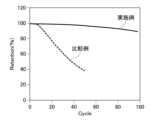
- FIG. 1 is a microscopic photograph of a main part of a solid state secondary battery according to an example. It is a graph showing the relationship between the number of cycles and capacity retention rate of solid secondary batteries according to Examples and Comparative Examples. It is a graph showing the relationship between the number of cycles and capacity retention rate of solid secondary batteries according to Examples and Comparative Examples.
- the solid secondary battery 1 As schematically shown in FIG. 1, the solid secondary battery 1 according to the present embodiment has a structure in which a positive electrode layer 20, a solid electrolyte layer 40, an intermediate layer 50, and a negative electrode layer 30 are laminated in this order. be done. Note that since FIG. 1 is a diagram schematically showing the configuration of the solid secondary battery 1 after charging and discharging, a metal deposit layer 60 is formed between the intermediate layer 50 and the negative electrode layer 30.
- the positive electrode layer 20 is a layer consisting of a positive electrode current collector 21 and a positive electrode active material layer 22 containing at least a positive electrode active material.
- the positive electrode current collector 21 is not particularly limited as long as it has the function of collecting current from the positive electrode layer, and examples thereof include aluminum, aluminum alloy, stainless steel, nickel, iron, titanium, etc. Among them, aluminum, Aluminum alloys and stainless steel are preferred. In addition, examples of the shape of the positive electrode current collector include a foil shape and a plate shape.
- the positive electrode active material contained in the positive electrode active material layer 22 may be the same as that used in the positive electrode layer of general solid-state batteries, and is not particularly limited.
- examples include a layered active material containing lithium, a spinel type active material, an olivine type active material, and the like.
- the positive electrode active material layer 22 may optionally contain a solid electrolyte from the viewpoint of improving charge transfer medium conductivity. Further, a conductive aid may optionally be included in order to improve conductivity. Furthermore, from the viewpoint of exhibiting flexibility, a binder may be optionally included. Regarding the solid electrolyte, conductive aid, and binder, those commonly used in solid batteries can be used.
- the negative electrode layer 30 is a layer consisting of a negative electrode current collector 31 and a negative electrode active material layer 32 containing at least a negative electrode active material.
- the negative electrode current collector 31 is not particularly limited as long as it has the function of collecting current from the negative electrode layer, and examples of the material of the negative electrode current collector include nickel, copper, stainless steel, and the like. Moreover, examples of the shape of the negative electrode current collector include foil shape, plate shape, and the like.
- the negative electrode active material contained in the negative electrode active material layer 32 known materials capable of intercalating and deintercalating charge transfer media such as lithium ions can be appropriately selected and used.
- lithium transition metal oxides such as lithium titanate, transition metal oxides such as TiO 2 , Nb 2 O 3 and WO 3 , Si, SiO, metal sulfides, metal nitrides, and artificial graphite, natural graphite, and graphite.
- carbon materials such as soft carbon and hard carbon, as well as metallic lithium, metallic indium, lithium alloys, and the like.
- the negative electrode active material is preferably metallic lithium. This is because the solid secondary battery 1 according to the present embodiment can preferably suppress the precipitation of dendrites when metallic lithium is used as the negative electrode active material.
- the negative electrode active material may be in the form of a powder or a thin film.
- the negative electrode active material layer 32 may optionally contain a solid electrolyte from the viewpoint of improving charge transfer medium conductivity. Further, a conductive aid may optionally be included in order to improve conductivity. Furthermore, from the viewpoint of exhibiting flexibility, a binder may be optionally included. Regarding the solid electrolyte, conductive aid, and binder, those commonly used in solid batteries can be used.
- the solid electrolyte layer 40 is a layer laminated between the positive electrode layer 20 and the negative electrode layer 30, and is a layer containing at least a solid electrolyte material. Charge transfer medium conduction between the positive electrode active material and the negative electrode active material can be performed through the solid electrolyte material contained in the solid electrolyte layer.
- the solid electrolyte material is not particularly limited as long as it has charge transfer medium conductivity, but examples include sulfide solid electrolyte materials, oxide solid electrolyte materials, nitride solid electrolyte materials, and halide solid electrolytes. Examples include materials.
- Li 2 SP 2 S 5 Li 2 SP 2 S 5 -LiI for lithium ion batteries.
- Li 2 S-P 2 S 5 means a sulfide solid electrolyte material using a raw material composition containing Li 2 S and P 2 S 5 , and other similar descriptions also apply. The same is true.
- oxide solid electrolyte materials include NASICON type oxides, garnet type oxides, perovskite type oxides, and the like in the case of lithium ion batteries.
- NASICON-type oxides include oxides containing Li, Al, Ti, P, and O (eg, Li 1.5 Al 0.5 Ti 1.5 (PO 4 ) 3 ).
- garnet-type oxides include oxides containing Li, La, Zr, and O (eg, Li 7 La 3 Zr 2 O 12 ).
- perovskite-type oxides include oxides containing Li, La, Ti, and O (for example, LiLaTiO 3 ).
- the porosity of the solid electrolyte layer 40 is lower than that of the intermediate layer 50 described below, for example, less than 10%. Further, the particle size of the solid electrolyte material 41 constituting the solid electrolyte layer 40 is, for example, 0.5 to 10 ⁇ m in median diameter (D50), and is preferably larger than the particles constituting the intermediate layer described later.
- the porosity of the solid electrolyte 40 can be determined, for example, using the following equation (1).
- the method for calculating the porosity is not limited to the above method, and may be calculated by instrumental analysis using BET, porosimeter, gas diffusion, etc., or image analysis using a scanning electron microscope, etc.
- the intermediate layer 50 is a layer laminated between the negative electrode layer 30 and the solid electrolyte layer 40.
- the intermediate layer 50 can suppress non-uniform precipitation of metal on the interface of the negative electrode layer 30 and can improve interfacial adhesion.
- the intermediate layer 50 preferably includes amorphous carbon 51 and metal nanoparticles 52.
- FIG. 2 is an enlarged view of the portion where the solid electrolyte layer 40, intermediate layer 50, and negative electrode layer 30 in FIG.
- FIG. 3 is a diagram corresponding to FIG. 2, and is a schematic diagram showing a state after the solid secondary battery 1 has been repeatedly charged and discharged.
- the charge transfer medium of the solid secondary battery 1 is Li ions.
- metallic lithium is deposited at the interface between the solid electrolyte layer and the negative electrode layer.
- the intermediate layer 50 of the solid state secondary battery 1 has electron conductivity and has voids through which Li ions can pass. Therefore, as shown in FIG. 3, as the solid secondary battery 1 is repeatedly charged and discharged, Li ions moving from the solid electrolyte layer 40 toward the negative electrode active material layer 32 pass through the intermediate layer 50 and A metal deposition layer 60 (a layer of metallic lithium) is formed between the layer 50 and the negative electrode active material layer 32. Thereby, the metal precipitated layer 60 can be uniformly formed.
- the intermediate layer 50 since the intermediate layer 50 has flexibility that can follow volume changes of each layer due to charging and discharging, even when the solid secondary battery 1 is repeatedly charged and discharged, interfacial adhesion can be maintained. The durability of the solid secondary battery 1 can be improved.
- the porosity of the intermediate layer 50 is higher than that of the solid electrolyte layer 40. Thereby, a void through which Li ions can pass can be formed inside the intermediate layer 50, and the intermediate layer 50 can be flexible and follow the volume change of the solid secondary battery 1.
- the porosity of the intermediate layer 50 can be, for example, 40 to 70%.
- a method for calculating the porosity of the intermediate layer 50 a method similar to the method for calculating the porosity of the solid electrolyte 40 can be applied.
- the intermediate layer 50 includes amorphous carbon 51.
- the amorphous carbon 51 does not react with lithium metal or the like to form an alloy, so that the formation of dendrites can be suppressed and the cycle characteristics of the solid secondary battery 1 can be improved.
- the amorphous carbon 51 include carbon blacks such as acetylene black, furnace black, and Ketjen black, coke, and activated carbon.
- the amorphous carbon 51 may be graphitizable carbon (soft carbon), non-graphitizable carbon (hard carbon), CNT (carbon nanotubes), fullerene, or graphene.
- Amorphous carbon here refers to carbon allotropes that do not exhibit a clear crystalline state, and strictly speaking, it is not amorphous but an aggregate of fine graphite crystals. In other words, amorphous carbon refers to carbon allotropes excluding diamond and graphite.
- the intermediate layer 50 includes metal nanoparticles 52.
- the electronic conductivity of the intermediate layer 50 can be increased, and the metal precipitated layer 60 can be formed more uniformly. Further, since the metal nanoparticles 52 have a higher Young's modulus than the amorphous carbon 51, the structure of the intermediate layer 50 can be maintained even when high-pressure pressing is performed when manufacturing the solid secondary battery 1.
- Examples of the metal nanoparticles 52 include tin (Sn), silicon (Si), zinc (Zn), magnesium (Mg), gold (Au), platinum (Pt), palladium (Pd), silver (Ag), and aluminum ( Examples include metal nanoparticles such as Al), bismuth (Bi), and antimony (Sb).
- the content of the metal nanoparticles 52 in the intermediate layer 50 is preferably more than 0% by mass and not more than 30% by mass.
- the particle size of the particles such as amorphous carbon 51 and metal nanoparticles 52 constituting the intermediate layer 50 is smaller than the particle size of the solid electrolyte material 41.
- the intermediate layer 50 can enter the gap between the solid electrolyte materials 41 forming the interface of the solid electrolyte layer 40, so that the contact area between the solid electrolyte layer 40 and the intermediate layer 50 can be increased. Adhesion can be improved.
- the particle diameter of the amorphous carbon 51 can be, for example, about 0.04 to 0.05 ⁇ m in median diameter (D50)
- the particle diameter of the metal nanoparticles 52 can be, for example, about 0.04 to 0.05 ⁇ m in median diameter (D50).
- a material with a diameter of about .07 ⁇ m can be used.
- the intermediate layer 50 preferably contains a binder as a binding material.
- the binder is not particularly limited, and binders commonly used in solid-state batteries can be used. Examples include acrylic acid polymers, cellulose polymers, styrene polymers, vinyl acetate polymers, urethane polymers, fluoroethylene polymers, and PVDF polymers.
- the solid secondary battery 1 according to the present embodiment is manufactured by stacking the positive electrode layer 20, the solid electrolyte layer 40, the intermediate layer 50, and the negative electrode layer 30 in the order shown in FIG. In addition, after the above-mentioned lamination, you may optionally press and integrate. Furthermore, a plurality of the structural units shown in FIG. 1 may be stacked as a unit battery.
- Example 1 [Preparation of solid electrolyte layer] An argyrodite-type sulfide solid electrolyte was used as the solid electrolyte material.
- Lithium nickel cobalt manganese composite oxide (NCM622) is used as the positive electrode active material, argyrodite sulfide solid electrolyte is used as the solid electrolyte, butyl butyrate is used as the solvent, carbon black is used as the conductive agent, and SBR (styrene butadiene rubber) type binder is used as the binder.
- a positive electrode layer was prepared by creating a slurry using the slurry, coating it on aluminum foil as a positive electrode current collector, and drying it.
- a negative electrode layer was produced by using metallic lithium as a negative electrode active material and bonding it to SUS foil as an electrode current collector.
- a slurry was created using Sn as metal nanoparticles, acetylene black (particle size 0.05 ⁇ m) as amorphous carbon, NMP (N-methyl-2-pyrrolidone) as a solvent, and a PVDF binder as a binding material.
- An intermediate layer was prepared by coating and drying.
- a metal deposited layer 60 is formed at the interface between the solid electrolyte layer 40 and the negative electrode layer, and the metal deposited layer 60 becomes porous. A condition was observed.
- the metal deposit layer 60 is formed at the interface between the intermediate layer 50 and the negative electrode layer, and the metal deposit layer 60 It was confirmed that the material was not porous.
- the solid-state secondary battery according to Example 1 exhibits a gradual decrease in capacity retention rate as the number of cycles increases, compared to the solid-state secondary battery according to Comparative Example 1.
- Favorable cycle characteristics were obtained.
- a metal deposit layer is formed between the intermediate layer and the negative electrode layer. 1. No metal deposited layer is formed between the intermediate layer and the negative electrode layer, or a metal deposited layer is formed within the solid electrolyte layer or between the intermediate layer and the solid electrolyte layer.
- the solid secondary battery according to each example has a discharge capacity retention rate (%) after a cycle test, and an average charge/discharge efficiency (%) from 1 to 50 cycles compared to the solid secondary battery according to each comparative example. ) is high, and it is clear that favorable cycle characteristics can be obtained.
Landscapes
- Chemical & Material Sciences (AREA)
- Engineering & Computer Science (AREA)
- Chemical Kinetics & Catalysis (AREA)
- Electrochemistry (AREA)
- General Chemical & Material Sciences (AREA)
- Manufacturing & Machinery (AREA)
- Materials Engineering (AREA)
- Physics & Mathematics (AREA)
- Condensed Matter Physics & Semiconductors (AREA)
- General Physics & Mathematics (AREA)
- Inorganic Chemistry (AREA)
- Secondary Cells (AREA)
- Battery Electrode And Active Subsutance (AREA)
Priority Applications (4)
| Application Number | Priority Date | Filing Date | Title |
|---|---|---|---|
| JP2024511928A JP7827832B2 (ja) | 2022-03-30 | 2023-03-22 | 固体二次電池 |
| KR1020247031729A KR20240155288A (ko) | 2022-03-30 | 2023-03-22 | 고체 이차 전지 |
| CN202380030297.3A CN118946998A (zh) | 2022-03-30 | 2023-03-22 | 固体二次电池 |
| US18/851,080 US20250219161A1 (en) | 2022-03-30 | 2023-03-22 | Solid-state secondary battery |
Applications Claiming Priority (2)
| Application Number | Priority Date | Filing Date | Title |
|---|---|---|---|
| JP2022055389 | 2022-03-30 | ||
| JP2022-055389 | 2022-03-30 |
Publications (1)
| Publication Number | Publication Date |
|---|---|
| WO2023189892A1 true WO2023189892A1 (ja) | 2023-10-05 |
Family
ID=88201190
Family Applications (1)
| Application Number | Title | Priority Date | Filing Date |
|---|---|---|---|
| PCT/JP2023/011101 Ceased WO2023189892A1 (ja) | 2022-03-30 | 2023-03-22 | 固体二次電池 |
Country Status (5)
| Country | Link |
|---|---|
| US (1) | US20250219161A1 (https=) |
| JP (1) | JP7827832B2 (https=) |
| KR (1) | KR20240155288A (https=) |
| CN (1) | CN118946998A (https=) |
| WO (1) | WO2023189892A1 (https=) |
Cited By (2)
| Publication number | Priority date | Publication date | Assignee | Title |
|---|---|---|---|---|
| JP2025148712A (ja) * | 2024-03-26 | 2025-10-08 | 本田技研工業株式会社 | 全固体電池及び全固体電池の製造方法 |
| WO2025211083A1 (ja) * | 2024-03-30 | 2025-10-09 | 本田技研工業株式会社 | リチウム金属電池 |
Citations (4)
| Publication number | Priority date | Publication date | Assignee | Title |
|---|---|---|---|---|
| JP2015092433A (ja) * | 2012-02-24 | 2015-05-14 | 住友電気工業株式会社 | 全固体リチウム二次電池 |
| JP2019033053A (ja) * | 2017-08-10 | 2019-02-28 | トヨタ自動車株式会社 | リチウム固体電池、およびリチウム固体電池の製造方法 |
| JP2021099958A (ja) * | 2019-12-23 | 2021-07-01 | 日産自動車株式会社 | 全固体リチウムイオン二次電池 |
| JP2021163622A (ja) * | 2020-03-31 | 2021-10-11 | 住友化学株式会社 | 固体電解質含有層 |
Family Cites Families (3)
| Publication number | Priority date | Publication date | Assignee | Title |
|---|---|---|---|---|
| JP5910737B2 (ja) | 2012-05-24 | 2016-04-27 | 株式会社村田製作所 | 全固体電池 |
| JP2018063850A (ja) * | 2016-10-13 | 2018-04-19 | 凸版印刷株式会社 | 積層体グリーンシート、全固体二次電池及びその製造方法 |
| JP7050419B2 (ja) | 2017-02-07 | 2022-04-08 | 三星電子株式会社 | 全固体型二次電池用負極及び全固体型二次電池 |
-
2023
- 2023-03-22 KR KR1020247031729A patent/KR20240155288A/ko active Pending
- 2023-03-22 US US18/851,080 patent/US20250219161A1/en active Pending
- 2023-03-22 CN CN202380030297.3A patent/CN118946998A/zh active Pending
- 2023-03-22 WO PCT/JP2023/011101 patent/WO2023189892A1/ja not_active Ceased
- 2023-03-22 JP JP2024511928A patent/JP7827832B2/ja active Active
Patent Citations (4)
| Publication number | Priority date | Publication date | Assignee | Title |
|---|---|---|---|---|
| JP2015092433A (ja) * | 2012-02-24 | 2015-05-14 | 住友電気工業株式会社 | 全固体リチウム二次電池 |
| JP2019033053A (ja) * | 2017-08-10 | 2019-02-28 | トヨタ自動車株式会社 | リチウム固体電池、およびリチウム固体電池の製造方法 |
| JP2021099958A (ja) * | 2019-12-23 | 2021-07-01 | 日産自動車株式会社 | 全固体リチウムイオン二次電池 |
| JP2021163622A (ja) * | 2020-03-31 | 2021-10-11 | 住友化学株式会社 | 固体電解質含有層 |
Cited By (3)
| Publication number | Priority date | Publication date | Assignee | Title |
|---|---|---|---|---|
| JP2025148712A (ja) * | 2024-03-26 | 2025-10-08 | 本田技研工業株式会社 | 全固体電池及び全固体電池の製造方法 |
| JP7818642B2 (ja) | 2024-03-26 | 2026-02-20 | 本田技研工業株式会社 | 全固体電池及び全固体電池の製造方法 |
| WO2025211083A1 (ja) * | 2024-03-30 | 2025-10-09 | 本田技研工業株式会社 | リチウム金属電池 |
Also Published As
| Publication number | Publication date |
|---|---|
| JPWO2023189892A1 (https=) | 2023-10-05 |
| JP7827832B2 (ja) | 2026-03-10 |
| US20250219161A1 (en) | 2025-07-03 |
| KR20240155288A (ko) | 2024-10-28 |
| CN118946998A (zh) | 2024-11-12 |
Similar Documents
| Publication | Publication Date | Title |
|---|---|---|
| KR102895248B1 (ko) | 리튬 석출물을 포함하는 전고체 전지 | |
| JP2023514346A (ja) | リチウム二次電池用正極材、これを含む正極及びリチウム二次電池 | |
| JP7064613B2 (ja) | 全固体二次電池用積層部材の製造方法及び全固体二次電池の製造方法 | |
| CN115668534A (zh) | 电池及电池的制造方法 | |
| JP2012243645A (ja) | 電極、および全固体型非水電解質電池 | |
| CN117638409A (zh) | 锂金属二次电池 | |
| JP7827832B2 (ja) | 固体二次電池 | |
| CN114649592A (zh) | 包含具有多层结构的锂存储层的全固态电池以及其制造方法 | |
| CN117917789A (zh) | 包括复合结构层的无阳极全固态电池及其制造方法 | |
| US20220181613A1 (en) | Anti-dendrite negative electrodes, and the electrochemical cells containing them | |
| CN119864480A (zh) | 全固体电池 | |
| CN115398666A (zh) | 负极材料及电池 | |
| WO2021260900A1 (ja) | リチウム2次電池、及びその使用方法 | |
| JP2024146931A (ja) | 固体二次電池 | |
| JP7827266B2 (ja) | 二次電池用負極、二次電池、および二次電池用負極の製造方法 | |
| JP7569299B2 (ja) | リチウムイオン電池用正極活物質及びその製造方法、並びに、リチウムイオン電池 | |
| CN115552662A (zh) | 电池及其制造方法 | |
| JP7643320B2 (ja) | リチウムイオン二次電池用正極、及び、リチウムイオン二次電池 | |
| US12308382B2 (en) | All-solid-state battery | |
| US20250174738A1 (en) | Method for producing all-solid-state battery | |
| CN120728003A (zh) | 固体二次电池及固体二次电池的中间层形成用涂布液的制造方法 | |
| US20250260067A1 (en) | Method of manufacturing solid-state secondary battery | |
| JP2023103175A (ja) | 負極構成部材、負極複合体及びこれらを含む全固体電池 | |
| JP2025044755A (ja) | 電池およびその製造方法 | |
| WO2025141751A1 (ja) | リチウム二次電池 |
Legal Events
| Date | Code | Title | Description |
|---|---|---|---|
| 121 | Ep: the epo has been informed by wipo that ep was designated in this application |
Ref document number: 23779906 Country of ref document: EP Kind code of ref document: A1 |
|
| ENP | Entry into the national phase |
Ref document number: 20247031729 Country of ref document: KR Kind code of ref document: A |
|
| WWE | Wipo information: entry into national phase |
Ref document number: 1020247031729 Country of ref document: KR |
|
| ENP | Entry into the national phase |
Ref document number: 2024511928 Country of ref document: JP Kind code of ref document: A |
|
| WWE | Wipo information: entry into national phase |
Ref document number: 202380030297.3 Country of ref document: CN |
|
| WWE | Wipo information: entry into national phase |
Ref document number: 18851080 Country of ref document: US |
|
| NENP | Non-entry into the national phase |
Ref country code: DE |
|
| 122 | Ep: pct application non-entry in european phase |
Ref document number: 23779906 Country of ref document: EP Kind code of ref document: A1 |
|
| WWP | Wipo information: published in national office |
Ref document number: 18851080 Country of ref document: US |