WO2023189500A1 - Véhicule du type à selle - Google Patents
Véhicule du type à selle Download PDFInfo
- Publication number
- WO2023189500A1 WO2023189500A1 PCT/JP2023/009706 JP2023009706W WO2023189500A1 WO 2023189500 A1 WO2023189500 A1 WO 2023189500A1 JP 2023009706 W JP2023009706 W JP 2023009706W WO 2023189500 A1 WO2023189500 A1 WO 2023189500A1
- Authority
- WO
- WIPO (PCT)
- Prior art keywords
- exhaust pipe
- vehicle
- downstream
- divided
- exhaust gas
- Prior art date
Links
- 239000003054 catalyst Substances 0.000 claims abstract description 54
- 238000011144 upstream manufacturing Methods 0.000 claims abstract description 47
- 239000007789 gas Substances 0.000 description 72
- 238000002485 combustion reaction Methods 0.000 description 23
- 238000001816 cooling Methods 0.000 description 10
- 230000005540 biological transmission Effects 0.000 description 9
- QVGXLLKOCUKJST-UHFFFAOYSA-N atomic oxygen Chemical compound [O] QVGXLLKOCUKJST-UHFFFAOYSA-N 0.000 description 7
- 239000001301 oxygen Substances 0.000 description 7
- 229910052760 oxygen Inorganic materials 0.000 description 7
- 230000003197 catalytic effect Effects 0.000 description 4
- 238000001514 detection method Methods 0.000 description 4
- 229910052751 metal Inorganic materials 0.000 description 4
- 239000002184 metal Substances 0.000 description 4
- 238000003466 welding Methods 0.000 description 4
- 239000003638 chemical reducing agent Substances 0.000 description 3
- KDLHZDBZIXYQEI-UHFFFAOYSA-N Palladium Chemical compound [Pd] KDLHZDBZIXYQEI-UHFFFAOYSA-N 0.000 description 2
- 238000007664 blowing Methods 0.000 description 2
- 230000000694 effects Effects 0.000 description 2
- 239000000446 fuel Substances 0.000 description 2
- 239000002828 fuel tank Substances 0.000 description 2
- 230000002093 peripheral effect Effects 0.000 description 2
- BASFCYQUMIYNBI-UHFFFAOYSA-N platinum Chemical compound [Pt] BASFCYQUMIYNBI-UHFFFAOYSA-N 0.000 description 2
- 239000000470 constituent Substances 0.000 description 1
- 238000002347 injection Methods 0.000 description 1
- 239000007924 injection Substances 0.000 description 1
- 230000037431 insertion Effects 0.000 description 1
- 238000003780 insertion Methods 0.000 description 1
- 238000009434 installation Methods 0.000 description 1
- 229910052763 palladium Inorganic materials 0.000 description 1
- 238000005192 partition Methods 0.000 description 1
- 229910052697 platinum Inorganic materials 0.000 description 1
- 239000011148 porous material Substances 0.000 description 1
- 238000000746 purification Methods 0.000 description 1
- 229910052703 rhodium Inorganic materials 0.000 description 1
- 239000010948 rhodium Substances 0.000 description 1
- MHOVAHRLVXNVSD-UHFFFAOYSA-N rhodium atom Chemical compound [Rh] MHOVAHRLVXNVSD-UHFFFAOYSA-N 0.000 description 1
- 238000004904 shortening Methods 0.000 description 1
Images


Classifications
-
- B—PERFORMING OPERATIONS; TRANSPORTING
- B62—LAND VEHICLES FOR TRAVELLING OTHERWISE THAN ON RAILS
- B62J—CYCLE SADDLES OR SEATS; AUXILIARY DEVICES OR ACCESSORIES SPECIALLY ADAPTED TO CYCLES AND NOT OTHERWISE PROVIDED FOR, e.g. ARTICLE CARRIERS OR CYCLE PROTECTORS
- B62J45/00—Electrical equipment arrangements specially adapted for use as accessories on cycles, not otherwise provided for
- B62J45/40—Sensor arrangements; Mounting thereof
- B62J45/41—Sensor arrangements; Mounting thereof characterised by the type of sensor
-
- B—PERFORMING OPERATIONS; TRANSPORTING
- B62—LAND VEHICLES FOR TRAVELLING OTHERWISE THAN ON RAILS
- B62J—CYCLE SADDLES OR SEATS; AUXILIARY DEVICES OR ACCESSORIES SPECIALLY ADAPTED TO CYCLES AND NOT OTHERWISE PROVIDED FOR, e.g. ARTICLE CARRIERS OR CYCLE PROTECTORS
- B62J45/00—Electrical equipment arrangements specially adapted for use as accessories on cycles, not otherwise provided for
- B62J45/40—Sensor arrangements; Mounting thereof
- B62J45/42—Sensor arrangements; Mounting thereof characterised by mounting
-
- B—PERFORMING OPERATIONS; TRANSPORTING
- B62—LAND VEHICLES FOR TRAVELLING OTHERWISE THAN ON RAILS
- B62K—CYCLES; CYCLE FRAMES; CYCLE STEERING DEVICES; RIDER-OPERATED TERMINAL CONTROLS SPECIALLY ADAPTED FOR CYCLES; CYCLE AXLE SUSPENSIONS; CYCLE SIDE-CARS, FORECARS, OR THE LIKE
- B62K11/00—Motorcycles, engine-assisted cycles or motor scooters with one or two wheels
- B62K11/02—Frames
- B62K11/10—Frames characterised by the engine being over or beside driven rear wheel
-
- B—PERFORMING OPERATIONS; TRANSPORTING
- B62—LAND VEHICLES FOR TRAVELLING OTHERWISE THAN ON RAILS
- B62M—RIDER PROPULSION OF WHEELED VEHICLES OR SLEDGES; POWERED PROPULSION OF SLEDGES OR SINGLE-TRACK CYCLES; TRANSMISSIONS SPECIALLY ADAPTED FOR SUCH VEHICLES
- B62M7/00—Motorcycles characterised by position of motor or engine
- B62M7/02—Motorcycles characterised by position of motor or engine with engine between front and rear wheels
-
- F—MECHANICAL ENGINEERING; LIGHTING; HEATING; WEAPONS; BLASTING
- F01—MACHINES OR ENGINES IN GENERAL; ENGINE PLANTS IN GENERAL; STEAM ENGINES
- F01M—LUBRICATING OF MACHINES OR ENGINES IN GENERAL; LUBRICATING INTERNAL COMBUSTION ENGINES; CRANKCASE VENTILATING
- F01M11/00—Component parts, details or accessories, not provided for in, or of interest apart from, groups F01M1/00 - F01M9/00
- F01M11/03—Mounting or connecting of lubricant purifying means relative to the machine or engine; Details of lubricant purifying means
-
- F—MECHANICAL ENGINEERING; LIGHTING; HEATING; WEAPONS; BLASTING
- F01—MACHINES OR ENGINES IN GENERAL; ENGINE PLANTS IN GENERAL; STEAM ENGINES
- F01N—GAS-FLOW SILENCERS OR EXHAUST APPARATUS FOR MACHINES OR ENGINES IN GENERAL; GAS-FLOW SILENCERS OR EXHAUST APPARATUS FOR INTERNAL COMBUSTION ENGINES
- F01N1/00—Silencing apparatus characterised by method of silencing
-
- F—MECHANICAL ENGINEERING; LIGHTING; HEATING; WEAPONS; BLASTING
- F01—MACHINES OR ENGINES IN GENERAL; ENGINE PLANTS IN GENERAL; STEAM ENGINES
- F01N—GAS-FLOW SILENCERS OR EXHAUST APPARATUS FOR MACHINES OR ENGINES IN GENERAL; GAS-FLOW SILENCERS OR EXHAUST APPARATUS FOR INTERNAL COMBUSTION ENGINES
- F01N13/00—Exhaust or silencing apparatus characterised by constructional features ; Exhaust or silencing apparatus, or parts thereof, having pertinent characteristics not provided for in, or of interest apart from, groups F01N1/00 - F01N5/00, F01N9/00, F01N11/00
- F01N13/08—Other arrangements or adaptations of exhaust conduits
-
- F—MECHANICAL ENGINEERING; LIGHTING; HEATING; WEAPONS; BLASTING
- F01—MACHINES OR ENGINES IN GENERAL; ENGINE PLANTS IN GENERAL; STEAM ENGINES
- F01N—GAS-FLOW SILENCERS OR EXHAUST APPARATUS FOR MACHINES OR ENGINES IN GENERAL; GAS-FLOW SILENCERS OR EXHAUST APPARATUS FOR INTERNAL COMBUSTION ENGINES
- F01N13/00—Exhaust or silencing apparatus characterised by constructional features ; Exhaust or silencing apparatus, or parts thereof, having pertinent characteristics not provided for in, or of interest apart from, groups F01N1/00 - F01N5/00, F01N9/00, F01N11/00
- F01N13/18—Construction facilitating manufacture, assembly, or disassembly
-
- F—MECHANICAL ENGINEERING; LIGHTING; HEATING; WEAPONS; BLASTING
- F01—MACHINES OR ENGINES IN GENERAL; ENGINE PLANTS IN GENERAL; STEAM ENGINES
- F01N—GAS-FLOW SILENCERS OR EXHAUST APPARATUS FOR MACHINES OR ENGINES IN GENERAL; GAS-FLOW SILENCERS OR EXHAUST APPARATUS FOR INTERNAL COMBUSTION ENGINES
- F01N3/00—Exhaust or silencing apparatus having means for purifying, rendering innocuous, or otherwise treating exhaust
- F01N3/08—Exhaust or silencing apparatus having means for purifying, rendering innocuous, or otherwise treating exhaust for rendering innocuous
- F01N3/10—Exhaust or silencing apparatus having means for purifying, rendering innocuous, or otherwise treating exhaust for rendering innocuous by thermal or catalytic conversion of noxious components of exhaust
- F01N3/24—Exhaust or silencing apparatus having means for purifying, rendering innocuous, or otherwise treating exhaust for rendering innocuous by thermal or catalytic conversion of noxious components of exhaust characterised by constructional aspects of converting apparatus
-
- F—MECHANICAL ENGINEERING; LIGHTING; HEATING; WEAPONS; BLASTING
- F01—MACHINES OR ENGINES IN GENERAL; ENGINE PLANTS IN GENERAL; STEAM ENGINES
- F01P—COOLING OF MACHINES OR ENGINES IN GENERAL; COOLING OF INTERNAL-COMBUSTION ENGINES
- F01P7/00—Controlling of coolant flow
- F01P7/02—Controlling of coolant flow the coolant being cooling-air
-
- F—MECHANICAL ENGINEERING; LIGHTING; HEATING; WEAPONS; BLASTING
- F02—COMBUSTION ENGINES; HOT-GAS OR COMBUSTION-PRODUCT ENGINE PLANTS
- F02B—INTERNAL-COMBUSTION PISTON ENGINES; COMBUSTION ENGINES IN GENERAL
- F02B61/00—Adaptations of engines for driving vehicles or for driving propellers; Combinations of engines with gearing
- F02B61/02—Adaptations of engines for driving vehicles or for driving propellers; Combinations of engines with gearing for driving cycles
-
- Y—GENERAL TAGGING OF NEW TECHNOLOGICAL DEVELOPMENTS; GENERAL TAGGING OF CROSS-SECTIONAL TECHNOLOGIES SPANNING OVER SEVERAL SECTIONS OF THE IPC; TECHNICAL SUBJECTS COVERED BY FORMER USPC CROSS-REFERENCE ART COLLECTIONS [XRACs] AND DIGESTS
- Y02—TECHNOLOGIES OR APPLICATIONS FOR MITIGATION OR ADAPTATION AGAINST CLIMATE CHANGE
- Y02A—TECHNOLOGIES FOR ADAPTATION TO CLIMATE CHANGE
- Y02A50/00—TECHNOLOGIES FOR ADAPTATION TO CLIMATE CHANGE in human health protection, e.g. against extreme weather
- Y02A50/20—Air quality improvement or preservation, e.g. vehicle emission control or emission reduction by using catalytic converters
Definitions
- the present invention relates to a straddle-type vehicle equipped with a unit swing engine.
- Conventional straddle-type vehicles are equipped with a unit swing engine, and a catalyst device is installed in the middle of the exhaust pipe connected to the internal combustion engine of the unit swing engine, and an exhaust gas sensor is installed upstream of the catalyst device in the exhaust pipe. is disclosed (see Patent Document 1).
- the exhaust gas sensor is attached to the exhaust pipe upstream of the catalytic device and measures the oxygen concentration of the exhaust gas before it passes through the catalytic device.
- the oxygen concentration in the exhaust gas can be detected more accurately by measuring the exhaust gas.
- an exhaust gas sensor is installed in the exhaust pipe downstream of the catalytic converter, depending on its installation position, it will be far away from the internal combustion engine, making it difficult to quickly warm up the exhaust gas sensor. If it is placed close to the opening, when the exhaust pipe becomes negative pressure, the flow of exhaust gas inside the exhaust pipe will be disturbed by the outside air flowing in from the atmosphere opening, which will affect the detection accuracy of the exhaust gas sensor. There are issues such as the effects of
- the present invention has been made in view of the above-mentioned problems, and includes a vehicle body frame, a cylinder portion arranged with the cylinder axis facing forward, a crankcase, and a crankshaft, and a link member is attached to the vehicle body frame.
- a unit swing engine swingably supported through the A straddle-type vehicle that is connected to the unit swing engine and includes an exhaust system that includes an exhaust pipe and a catalyst device disposed in the middle of the exhaust pipe, the exhaust pipe extends downward from the unit swing engine;
- the exhaust pipe includes a catalyst device housing exhaust pipe that houses the catalyst device therein, an upstream exhaust pipe connected to the upstream side of the catalyst device housing exhaust pipe, and a downstream side of the catalyst device housing exhaust pipe.
- the exhaust gas sensor and the catalytic device include, in a side view of the vehicle body, a first imaginary line connecting a link member connecting portion that connects the link member to the vehicle body frame and a rotation center of the crankshaft;
- the straddle type is located in a region between an exhaust pipe connecting portion of the unit swing engine to which an end of the exhaust pipe is connected and a second imaginary line connecting the link member connecting portion. It is a vehicle.
- the exhaust gas sensor in the downstream exhaust pipe on the downstream side of the catalyst device, the exhaust gas after passing through the catalyst device can be measured and the oxygen concentration in the exhaust gas can be detected with higher accuracy.
- the distance between the exhaust gas sensor and the internal combustion engine it is possible to warm up the exhaust gas sensor quickly.
- the exhaust gas sensor since the exhaust gas sensor is located far from the atmosphere opening of the exhaust pipe, the exhaust gas sensor To improve the accuracy of an exhaust gas sensor without affecting the detection accuracy of the exhaust gas sensor even if the flow of exhaust gas in the exhaust pipe is disturbed by outside air flowing in from the atmosphere opening when the inside of the pipe becomes negative pressure. I can do it.
- the downstream exhaust pipe when the vehicle is viewed from below, at least a portion of the downstream exhaust pipe is located on an extension line of the vehicle body frame, At least a portion of the exhaust gas sensor overlaps the vehicle body frame when viewed from the front of the vehicle.
- At least a portion of the downstream exhaust pipe is located on an extension of the vehicle body frame when viewed from the bottom of the vehicle, and at least a portion of the exhaust gas sensor overlaps with the vehicle body frame when viewed from the front of the vehicle. It can protect you from obstacles such as flying stones from the front.
- the downstream exhaust pipe is located outside the crankcase in the vehicle width direction when viewed from the bottom of the vehicle;
- the crankcase has an oil filter that is taken out toward the side of the vehicle,
- the exhaust gas sensor is arranged on a downstream exhaust pipe that is forward of the oil filter when viewed from the side of the vehicle.
- the exhaust gas sensor S1 when removing the oil filter 66 toward the side of the vehicle, the exhaust gas sensor S1 can be easily removed without becoming an obstacle.
- the present invention includes a fan that introduces outside air into the unit swing engine, and a fan cover that covers the fan from the side of the vehicle,
- the downstream exhaust pipe is characterized in that it does not overlap with the outside air inlet of the fan cover when viewed from the side of the vehicle.
- the downstream exhaust pipe is arranged at a position that does not overlap with the outside air inlet of the fan cover when viewed from the side of the vehicle, so warm air around the downstream exhaust pipe is difficult to be sucked into the power unit. This increases the cooling efficiency of the fan inside the power unit.
- the present invention is characterized in that a mesh portion is provided at the outer edge of the fan cover.
- the air inside the fan cover is discharged by the fan from the mesh part at the outer edge of the fan cover, so that the downstream side exhaust pipe near the fan cover can be cooled by blowing air, and the exhaust pipe can be cooled.
- the rigidity of the constituent metal can be increased.
- the present invention is characterized in that at least a portion of the exhaust pipe has a divided body structure.
- the exhaust pipe by making the exhaust pipe into a divided structure, it becomes easier to create a curved portion with a small curvature, and there are fewer restrictions regarding the curvature of the pipe.
- the exhaust pipe has a divided body structure in at least two places, At least one divided body structure is a divided body structure in which the divided edges of each divided body are joined by a matching structure to be integrated, In another divided body structure, the divided edge of one divided body has a jockle part that protrudes outward so as to fit the divided edge of the other divided body, and the divided edge of one divided body and the divided edge of the other divided body are connected to each other. It is characterized by a divided body structure in which the edges are joined and integrated by a jockle joint structure.
- the joint area of the divided bodies is larger in the divided body structure joined by the jockle alignment structure than in the divided body structure joined by the jockle alignment structure. Therefore, if all of the split structures at two or more locations are only split structures with a jockle alignment structure, the joint between the halves will be stronger compared to a split structure with a jockle alignment structure, but it will not cause heat damage.
- the curved portion of the metal exhaust pipe receives a force that returns it to a straight line, stress is concentrated at the joints between the divided bodies.
- the rigidity can be lowered and stress can be dispersed.
- the exhaust gas after passing through the catalyst device can be measured and the oxygen concentration in the exhaust gas can be detected with higher accuracy.
- the distance between the exhaust gas sensor and the internal combustion engine can be shortened, making it possible to warm up the exhaust gas sensor quickly.Furthermore, since the exhaust gas sensor is placed far from the atmosphere opening of the exhaust pipe, the exhaust gas sensor can be warmed up quickly. Even if the flow of exhaust gas inside the exhaust pipe is disturbed by outside air flowing in from the atmosphere opening when the inside of the pipe becomes negative pressure, it does not affect the detection accuracy of the exhaust gas sensor, and the accuracy of the exhaust gas sensor can be improved. can.
- FIG. 1 is an overall left side view of a motorcycle to which an intake structure for an internal combustion engine according to an embodiment of the present invention is applied.
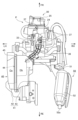
- FIG. 2 is an enlarged right side view of essential parts of the vehicle in FIG. 1.
- FIG. FIG. 2 is a left side view of the power unit, intake structure device, and exhaust device in FIG. 1;
- FIG. 3 is a plan view of FIG. 2;
- FIG. 2 is a bottom view of essential parts of the motorcycle.
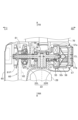
- FIG. 3 is a partial sectional view taken along the crankshaft of the internal combustion engine of the power unit.
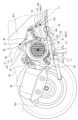
- FIG. 3 is an enlarged left side view of essential parts of the vehicle of FIG. 2, showing a state in which the internal combustion engine is suspended on the vehicle body frame.
- FIG. 2 is a front view of the main parts of the vehicle as seen from the front with the cover removed. It is a perspective view showing a part of exhaust pipe.
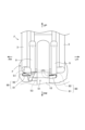
- FIG. 3 is a front view of the exhaust pipe in a state where the first upstream exhaust pipe is represented by a virtual line. It is a sectional view taken along the line XI-XI in FIG. 9. It is a sectional view taken along the line XII-XII in FIG. 9. It is a figure showing other attachment positions of an exhaust gas sensor. It is a figure showing still another attachment position of an exhaust gas sensor.
- the saddle type vehicle of this embodiment is a scooter type motorcycle 1, a left side view of which is shown in FIG.
- FR refers to the front
- RE refers to the forward direction
- LH indicates left
- RH indicates right
- UP indicates upward
- DW indicates downward.
- a front section 1F and a rear section 1R of the vehicle body are connected via a low floor section 1C, and the body frame F, which forms the skeleton of the vehicle body, is generally connected to the down tube 3. and main pipe 4. That is, a down tube 3 extends downward from the head pipe 2 at the front part 1F of the vehicle body, and the down tube 3 is bent horizontally at the lower end and extends rearward under the floor part 1C, and at the rear end, a pair of left and right main pipes 4 are provided. are connected, and the main pipe 4 forms an inclined part 4a extending diagonally upward rearward from the connecting part, and the upper part of the inclined part 4a is further bent to form a horizontal part 4b extending rearward substantially horizontally. .
- a storage box 5 is supported at the front, a fuel tank (not shown) is supported at the rear, and a sheet 7 covers the storage box 5 and the fuel tank above.
- a handle 8 is provided above the head pipe 2, which is pivotally supported, and a front fork 9 extends downward, and a front wheel 10 is pivotally supported at the lower end of the front fork 9.
- the vertically oriented parts of the head pipe 2 and down tube 3 are covered from the front and back by the front cover 1a and the leg shield 1b, and in the floor part 1C, the longitudinally oriented part of the down tube 3 is covered by the lower side cover 1c.
- the main pipe 4 is covered on the left, right, and rear sides by the body cover 1d.
- the motorcycle 1 is equipped with a power unit P located below the main pipe 4 and serving as a unit swing engine.
- the power unit P has a single-cylinder, four-stroke, air-cooled internal combustion engine 20 disposed at its front, and a belt-type continuously variable transmission at its rear.
- the power unit P is provided with a pair of left and right engine hangers 22h that protrude forward from the top of its crankcase 22.
- a link member 11 is protruded from the rear of the main pipe 4, and the end of the engine hanger 22h is connected to the link member 11 via a pivot shaft 12, so that the power unit P is swingably connected to the vehicle body frame F. Supported.
- the internal combustion engine 20 includes a crankcase 22, a cylinder block 23, a cylinder head 24, and a head cover 25, which are stacked one on top of the other in order, and are tilted significantly forward to a nearly horizontal state with the cylinder axis C facing forward. It is installed so that it protrudes forward in a posture.
- a crankshaft 21 is rotatably supported by the crankcase 22 so as to be oriented in the vehicle width direction.
- an intake port 24a is formed on the upper surface side of the cylinder head 24, and an inlet pipe 31 serving as an intake pipe extends upward from the intake port 24a.
- An exhaust port 24b is formed on the lower surface side of the cylinder head 24, and an exhaust pipe 51 extends downward from the exhaust port 24b.
- a spark plug 26 is fitted into the cylinder head 24 near the center head cover 25, and an oxygen concentration sensor is installed at a location where the exhaust pipe 51 extends, as shown in FIG. 27 is inserted.
- crankcase 22 is divided into left and right parts, and consists of a left crankcase part 22L and a right crankcase part 22R. 22R are rotatably supported via main bearings 21b and 21b, respectively.
- An AC generator 55 is provided on the right shaft portion of the crankshaft 21, and a centrifugal cooling fan 56 is integrally attached to an outer rotor 55r of the AC generator 55.
- a fan cover 57 that covers the right crankcase portion 22R from the right side accommodates a centrifugal cooling fan 56 therein.
- the fan cover 57 is formed with a grill 57g that is an outside air inlet facing the centrifugal cooling fan 56.
- the fan cover 57 has a mesh portion 57f formed in an area diagonally below the rear of the outer edge 57e surrounding the grille 57g, and the outside air introduced from the grille 57g flows through the centrifugal cooling fan 56. Due to the rotational force, the fan cover 57 is discharged from the mesh portion 57f.
- a shroud 70 surrounds the cylinder block 23 and cylinder head 24, and the shroud 70 is connected to the fan cover 57 on the right side.
- the left crankcase portion 22L extends rearward and also serves as a transmission case portion, and a transmission case cover 65 covers the transmission case portion (left crankcase portion) 22L from the left side.
- a belt type continuously variable transmission 60 is provided.
- a drive chain sprocket 58 is provided on the left shaft portion of the crankshaft 21 adjacent to the main bearing 21b, and a drive pulley 61 of a belt type continuously variable transmission 60 is provided on the left shaft end portion.
- a cam chain 59 wrapped around a drive chain sprocket 58 transmits power to the valve mechanism on the cylinder head 24 side.
- the reduction gear output shaft of the reduction mechanism 64 provided at the rear of the belt type continuously variable transmission 60 is a rear axle 28a, and the rear wheel 28 is provided on the rear axle 28a.
- a rear cushion (not shown) is interposed between the upper end of the rear portion of the transmission case portion 22L that accommodates the speed reduction mechanism 64 and the upper bent portion of the main pipe 4.
- a driven pulley 63 of a belt type continuously variable transmission 60 is pivotally supported on a reducer input shaft 64a of a reduction mechanism 64, and a drive pulley 61 provided on the crankshaft 21 and a reducer input shaft 64a of a reduction mechanism 64 are supported.
- a belt 62 is wound around a driven pulley 63 provided on the shaft 64a, and the power of the internal combustion engine 20 is transmitted to the driven pulley 63 via the belt 62, and the rotation of the driven pulley 63 is controlled via a centrifugal clutch (not shown).
- the power is transmitted to the speed reducer input shaft 64a of the speed reduction mechanism 64, the speed is reduced by the speed reduction mechanism 64, and the power is transmitted to the rear wheels 28.
- an outside air suction fan 61F is formed on the left half of the drive pulley 61.
- an oil filter 66 is disposed below the crankcase 22 and taken out toward the side of the vehicle, and the oil filter 66 supplies oil to various parts of the internal combustion engine 20. is filtered.
- an intake device 30 that takes in outside air and sends it to the internal combustion engine 20 is connected to the intake port 24a of the internal combustion engine 20.
- the intake device 30 includes an air cleaner device 40 that takes in and purifies outside air, a connecting tube 36 connected to the air cleaner device 40, and a throttle body 33 connected to the downstream side of the connecting tube 36.
- the inlet pipe 31 is connected to the upstream side of a throttle body 33 in which a butterfly-type throttle valve (not shown) is provided, and these constitute an intake system.
- the intake port 24a and the inlet pipe 31 are provided with a fuel injection valve 37 that injects fuel into the intake passage.
- the intake device 30 will be further explained.
- the air cleaner element 44 is partitioned into an unpurified chamber Ca on the unpurified chamber case 42 side and a purified chamber Cb on the purified chamber case 43 side by a partition portion 45 in which the air cleaner element 44 is disposed.
- an air introduction pipe 47 through which running wind and the like are taken in is arranged such that its opening 47a faces forward.
- the intake air introduced from the opening 47a passes through the air cleaner element 44 from within the unpurified chamber Ca, is purified, and is sent to the purified chamber Cb.
- the purification chamber Cb of the air cleaner device 40 is communicated with the throttle body 33 through an elastically deformable connecting tube 36 made of rubber.
- an exhaust device 50 is connected to the downstream end of the exhaust port 24b of the cylinder head 24.
- the lower surface of the cylinder head 24 is provided with an exhaust pipe connecting portion 24c to which the upstream side of the exhaust device 50 is connected.
- the exhaust system 50 includes an exhaust pipe 51 that is connected to the exhaust port 24b of the internal combustion engine 20 and discharges exhaust gas, a catalyst device 53 that is disposed inside the exhaust pipe 51 and purifies the exhaust gas, and a catalyst device 53 that is disposed inside the exhaust pipe 51 and purifies the exhaust gas. It is equipped with a muffler 52 connected downstream, and these constitute an exhaust system.
- the exhaust pipe 51 communicates with the exhaust port 24b and extends downward from the lower surface of the cylinder head 24, then bends diagonally forward to the left, and then curves further rearward.
- the muffler 52 is bent from the lower part of the crankcase 22 to the right, moves from the left side to the right side of the lower part of the crankcase 22, and further bent toward the rear, and then extends rearward and is connected to a muffler 52 disposed on the right side of the rear wheel 28.
- a catalyst device 53 is provided in the middle of the exhaust pipe 51, and the exhaust pipe 51 is connected to a catalyst device housing exhaust pipe 100 in which the catalyst device 53 is housed, and to the upstream side of the catalyst device housing exhaust pipe 100. It is composed of an upstream exhaust pipe 80 and a downstream exhaust pipe 90 connected to the downstream side of the catalyst device housing exhaust pipe 100.
- the downstream exhaust pipe 90 is arranged so that at least a portion thereof is located on an extension line of the vehicle body frame F and is located outside the crankcase 22 in the vehicle width direction when viewed from the bottom of the vehicle. has been done. Furthermore, as shown in FIG. 2, the downstream exhaust pipe 90 is arranged at a position that does not overlap with the grill 57g serving as an outside air inlet of the fan cover 57 when viewed from the side, so that warm air around the exhaust pipe 51 is not introduced. It looks like this.
- Exhaust gas discharged from the internal combustion engine 20 passes through the upstream exhaust pipe 80 from the exhaust port 24b, passes through the catalyst device 53 in the catalyst device housing exhaust pipe 100, and is purified, and then passes through the downstream exhaust pipe 90 and the muffler. 52 and is discharged to the outside air from the atmosphere opening 52a of the muffler 52.
- the catalyst device 53 is a honeycomb-like porous structure having a large number of pores extending along its axial direction, and supports, for example, platinum, rhodium, and palladium as a catalyst for decomposing exhaust gas components.
- the upstream exhaust pipe 80 of the exhaust pipe 51 includes a vertical part 80a extending downward from the exhaust pipe connection part 24c of the cylinder head 24, and a lateral extending part extending in front of the catalyst device 53 to the other side with respect to the crankcase split surface.
- the upstream exhaust pipe 80 includes a first upstream exhaust pipe 81 connected to the exhaust port 24b, and a second upstream exhaust pipe 81 connected to the downstream end 81b of the first upstream exhaust pipe 81. It consists of a tube 82.
- the upstream exhaust pipe 80 is divided into a first upstream exhaust pipe 81 and a second upstream exhaust pipe 82 in the middle of the curved portion 80c of the upstream exhaust pipe 80.
- the upstream end 82a of the second upstream exhaust pipe 82 is larger in diameter than the downstream end 81b of the first upstream exhaust pipe 81.
- the first upstream exhaust pipe 81 and the second upstream exhaust pipe 82 are connected in the circumferential direction after fitting the downstream end 81b of the first upstream exhaust pipe 81 into the upstream end 82a of the second upstream exhaust pipe 82. They are joined together by welding to form an upstream exhaust pipe 80.
- a flange portion 80d that is attached to the exhaust pipe connection portion 24c of the internal combustion engine 20 is fixed to the upstream end 81a of the first upstream exhaust pipe 81.
- a pair of bolt insertion holes 80e are provided in the flange portion 80d, and as shown in FIG. 5, the flange portion 80d is attached to the exhaust pipe connecting portion 24c of the cylinder head 24 with bolts 69.
- the downstream end 82b of the second upstream exhaust pipe 82 is connected to the upstream end 100a of the catalyst device housing exhaust pipe 100.
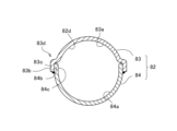
- the second upstream exhaust pipe 82 has a divided body structure that is approximately divided into two parts along the exhaust flow direction, and is composed of a first divided body 83 and a second divided body 84. It is configured. As shown in FIG. 11, when the first divided body 83 and the second divided body 84 are combined, the inner circumferential surface 82d of the second upstream exhaust pipe 82 is the same as the inner circumferential surface 83a of the first divided body 83.
- the inner peripheral surface 84a of the two-part body 84 forms a substantially circular shape.
- the divided end edge 83b of the first divided body 83 and the divided end edge 83b of the second divided body 84 are fitting parts 83c and 84c, respectively, and the fitting part 83c of the first divided body 83 is the second divided part 83b.
- a jockle portion 84d is formed which protrudes outward by a dimension corresponding to the plate thickness at the fitting portion 84c of the body 84 and extends along the dividing edge 84b.
- the first divided body 83 and the second divided body 84 are integrally joined by welding, with their fitting portions 83c and 84c forming a so-called jockle joint structure.
- the downstream exhaust pipe 90 is connected to the downstream end 100b of the catalyst device housing exhaust pipe 100, extends to the right side from the catalyst device housing exhaust pipe 100, and then extends rearward. It extends toward the rear wheel 28 and is connected to the muffler 52 on the right side of the rear wheel 28.
- the downstream exhaust pipe 90 is arranged so that at least a portion thereof is located on an extension line of the vehicle body frame F.
- the downstream exhaust pipe 90 includes a first downstream exhaust pipe 91 whose upstream end 91a is connected to the downstream end 100b of the catalyst device housing exhaust pipe 100, and a first downstream exhaust pipe 91 whose upstream end 92a is connected to the downstream end 100b of the catalyst device housing exhaust pipe 100.
- a second downstream exhaust pipe 92 is connected to the downstream end 91b of the side exhaust pipe 91.
- the downstream end b of the first downstream exhaust pipe 91 is larger in diameter than the upstream end 92a of the second downstream exhaust pipe 92.
- the first downstream exhaust pipe 91 and the second downstream exhaust pipe 92 are connected in the circumferential direction after the upstream end 92a of the second downstream exhaust pipe 92 is fitted into the downstream end 91b of the first downstream exhaust pipe 91. They are joined together by welding to form a downstream exhaust pipe 90.
- the first downstream exhaust pipe 91 has a divided body structure that is approximately divided into two parts along the exhaust flow direction, and is composed of a first divided body 93 and a second divided body 94. It is configured. As shown in FIG. 12, when the first divided body 93 and the second divided body 94 are combined, the inner circumferential surface 91d of the first downstream exhaust pipe 91 is the same as the inner circumferential surface 93a of the first divided body 93.
- the inner peripheral surface 94a of the two-part body 94 forms a substantially circular shape.
- the divided edge 93b of the first divided body 93 and the divided edge 93b of the second divided body 94 are each folded outward and overlapped, forming a so-called folded structure.
- the first divided body 93 and the second divided body 94 have divided edges 93b and 94b arranged in a stacked structure, and the overlapping ends are joined by welding to be integrated.
- a divided body structure joined by a matching structure may be adopted, and the other divided body structures are divided bodies joined by a jockle matching structure. It may be a structure.
- an exhaust gas sensor S1 is provided in the exhaust pipe 90 on the downstream side of the exhaust pipe 51 to detect the oxygen concentration, etc. in the exhaust gas after passing through the catalyst device 53 in order to purify the exhaust gas. ing.
- Exhaust gas sensor S1 is a LAF sensor or an O2 sensor.
- the exhaust gas sensor S1 is attached so as to be inserted into the exhaust pipe 51 from the upper surface of the second downstream exhaust pipe 92.
- the exhaust gas sensor S1 is provided in the downstream exhaust pipe 90 in a predetermined region located on the lower right side of the internal combustion engine 20, as shown in FIG.
- the exhaust gas sensor S1 and the catalyst device 53 are arranged in a region surrounded by the first imaginary line L1 and the second imaginary line L2 in FIG.
- the first imaginary line L1 connects the link member connecting portion 13, which is the location where the link member 11 and the main pipe 4 of the vehicle body frame F are joined, and the rotation center CL of the crankshaft 21 of the internal combustion engine 20, when viewed from the side of the vehicle.
- This is an imaginary line connecting the .
- the second imaginary line L2 is an imaginary line connecting the link member connecting portion 13 and the exhaust pipe connecting portion 24c to which the exhaust pipe 51 is connected to the internal combustion engine 20.
- the exhaust gas sensor S1 and the catalyst device 53 By disposing the exhaust gas sensor S1 and the catalyst device 53 in the area surrounded by the first imaginary line L1 and the second imaginary line L2 in FIG. 7, they can be arranged compactly. Furthermore, by arranging the exhaust gas sensor S1 and the catalyst device 53 at a position close to the exhaust port 24b of the internal combustion engine 20, it becomes possible to quickly warm up the exhaust gas sensor S1 and the catalyst device 53.
- the exhaust gas sensor S1 is provided on the downstream exhaust pipe 90 on the front side of the vehicle compared to the oil filter 66 when viewed from the side of the vehicle, and the oil filter 66 is disposed toward the side of the vehicle.
- the exhaust gas sensor S1 can be easily worked without becoming an obstacle.
- the exhaust gas sensor S1 is arranged at a position where at least a portion thereof overlaps with the vehicle body frame F, to prevent damage from obstacles such as flying stones from the front.
- the exhaust gas sensor S1 is attached from above the second downstream exhaust pipe 92, but it may be attached at a position that satisfies the above conditions, for example, as shown in FIG. It may be attached from above the first downstream exhaust pipe 91, or it may be attached to the rear of the first downstream exhaust pipe 91 as shown in FIG.
- the motorcycle 1, which is a straddle-type vehicle according to the embodiment of the present invention, is configured as described above, it has the following effects.
- the motorcycle 1 includes a body frame F, a cylinder block 23 arranged with the cylinder axis C facing forward, a crank case 22, and a crankshaft 21.
- a power unit P that is movably supported; and an exhaust device 50 that is connected to the power unit P and includes an exhaust pipe 51 and a catalyst device 53 disposed in the middle of the exhaust pipe 51, and the exhaust pipe 51 is connected to the power unit
- the exhaust pipe 51 includes a catalyst device housing exhaust pipe 100 that houses the catalyst device 53 therein, an upstream side exhaust pipe 80 connected to the upstream side of the catalyst device housing exhaust pipe 100, and a catalyst device housing exhaust pipe 100 that houses the catalyst device 53 therein.
- a downstream exhaust pipe 90 is connected to the downstream side of the device housing exhaust pipe 100, and the downstream exhaust pipe 90 is provided with an exhaust gas sensor S1, and the exhaust gas sensor S1 and the catalyst device 53 are , a first imaginary line L1 connecting the link member connecting portion 13 that connects the link member 11 to the vehicle body frame F and the rotation center CL of the crankshaft 21, and an exhaust pipe connection of the power unit P to which the end of the exhaust pipe 51 is connected. It is located in a region between the second imaginary line L2 connecting the portion 24c and the link member connecting portion 13.
- the exhaust gas sensor S1 in the downstream exhaust pipe 90 on the downstream side of the catalyst device 53, the exhaust gas after passing through the catalyst device 53 is measured and the oxygen concentration in the exhaust gas is determined.
- the exhaust gas sensor S1 can detect the atmosphere in the exhaust pipe 51. Since the exhaust gas sensor is located far from the opening 52a, even if the flow of exhaust gas in the exhaust pipe 51 is disturbed by the outside air flowing in from the atmosphere opening 52a when the pressure inside the exhaust pipe 51 becomes negative, the exhaust gas sensor The accuracy of the exhaust gas sensor S1 can be improved without affecting the detection accuracy of S1.
- At least a portion of the downstream exhaust pipe 90 is located on an extension line of the body frame F, and when viewed from the front of the vehicle, at least a portion of the exhaust gas sensor S1 overlaps with the body frame F, so that from the front of the vehicle can be protected from obstacles such as flying stones.
- downstream exhaust pipe 90 is located outside the crankcase 22 in the vehicle width direction when viewed from the bottom of the vehicle, and the crankcase 22 has an oil filter 66 that is taken out toward the side of the vehicle, and an exhaust gas sensor.
- S1 is disposed on the downstream exhaust pipe 90 on the front side of the vehicle compared to the oil filter 66 when viewed from the side of the vehicle, so when the oil filter 66 is taken out toward the side of the vehicle, the exhaust gas sensor S1 does not get in the way of obstacles. You can work easily without having to worry about it.
- centrifugal cooling fan 56 that introduces outside air into the power unit P
- a fan cover 57 that covers the centrifugal cooling fan 56 from the side of the vehicle. Since it is placed in a position that does not overlap with the grill 57g serving as an inlet, warm air around the downstream exhaust pipe 90 is difficult to be sucked into the power unit P, increasing the cooling efficiency in the power unit P by the centrifugal cooling fan 56. be able to.
- the outer edge 57e of the fan cover 57 is provided with a mesh portion 57f, the air inside the fan cover 57 is discharged from the mesh portion 57f by the rotation of the centrifugal cooling fan 56.
- the downstream exhaust pipe 90 can be cooled by blowing air, and the rigidity of the metal forming the exhaust pipe 51 can be increased.
- the exhaust pipe 51 is composed of the second upstream exhaust pipe 82 and the first downstream exhaust pipe 91 as a divided body structure, it is easy to create a curved part with a small curvature, and the curvature of the pipe is There are fewer restrictions.
- the exhaust pipe 51 has at least two divided body structures 82 and 91, at least one of which has a divided body structure such as the first downstream exhaust pipe 91, and each first The divided end edges 93b and 94b of the divided body 93 and the second divided body 94 are joined by an interlocking structure to form a unified divided body structure, and the other divided bodies such as the second upstream exhaust pipe 82
- the divided end edge 83b of one first divided body 83 is made into a jockle portion 84d that protrudes outward so as to fit the divided end edge 84b of the second divided body 84, and the divided end edge 83b and the divided end The edges 84b are joined together by a jockle joint structure to form a divided body structure.
- the joint area of the divided bodies is larger in the divided body structure joined by the jockle-joining structure than in the divided body structure joined by the jockle-joining structure. Therefore, if all of the split structures at two or more locations are only split structures with a jockle alignment structure, the joint between the halves will be stronger compared to a split structure with a jockle alignment structure, but it will not cause heat damage.
- the curved portion of the metal exhaust pipe receives a force that returns it to a straight line, stress is concentrated at the joints between the divided bodies.
- the rigidity can be lowered and stress can be dispersed.
- P...power unit C...cylinder axis, CL...crankshaft rotation center, F...body frame, S1...exhaust gas sensor, 1...Motorcycle, L1...first virtual line, L2...second virtual line, 11...Link member, 13...Link member connection part, 20... Internal combustion engine, 21... Crankshaft, 22... Crank case, 23... Cylinder block, 24... Cylinder head, 24c...
- Exhaust pipe connection part 50...Exhaust device, 51...Exhaust pipe, 53...Catalyst device, 56...Fan, 57...Fan cover, 57e...Outer edge, 57f...Mesh part, 57g...Grill, 80...upstream exhaust pipe, 82...second upstream exhaust pipe, 83...divided body, 83b...divided edge, 84...divided body, 84b...divided edge, 84d...jockle portion, 90...downstream exhaust pipe, 91...first downstream exhaust pipe, 93...divided body, 93b...divided edge, 94...divided body, 94b...divided edge, 100...Catalyst device housing exhaust pipe.
Landscapes
- Engineering & Computer Science (AREA)
- Mechanical Engineering (AREA)
- Chemical & Material Sciences (AREA)
- Combustion & Propulsion (AREA)
- General Engineering & Computer Science (AREA)
- Chemical Kinetics & Catalysis (AREA)
- Transportation (AREA)
- Health & Medical Sciences (AREA)
- Toxicology (AREA)
- Exhaust Gas After Treatment (AREA)
Abstract
Est fourni un véhicule du type à selle comprenant un cadre de carrosserie de véhicule (F), un moteur oscillant unitaire (P) supporté de manière oscillante par le cadre de carrosserie de véhicule (F) par l'intermédiaire d'un élément de liaison (11), et un dispositif d'échappement (50) équipé d'un tuyau d'échappement (51) et d'un dispositif de catalyseur (53). Le tuyau d'échappement (51) s'étend vers le bas à partir du moteur oscillant unitaire (P) et comprend un tuyau d'échappement de réception de dispositif de catalyseur (100), un tuyau d'échappement amont (80) et un tuyau d'échappement aval (90). Un capteur de gaz d'échappement (S1) est agencé dans le tuyau d'échappement aval (90). Dans une vue latérale de la carrosserie de véhicule, le capteur de gaz d'échappement (S1) et le dispositif de catalyseur (53) sont positionnés dans une zone entre une première ligne virtuelle (L1) raccordant le centre de rotation (CL) d'un vilebrequin (21) et une section de raccordement d'élément de liaison (13) reliant l'élément de liaison (11) au cadre de carrosserie de véhicule (F) et une seconde ligne virtuelle (L2) raccordant la section de raccordement d'élément de liaison (13) et une section de raccordement de tuyau d'échappement (24c) à laquelle l'extrémité du tuyau d'échappement (51) est raccordée. Le véhicule du type à selle permet ainsi un réchauffage précoce du capteur de gaz d'échappement, supprime une turbulence de gaz d'échappement dans le tuyau et améliore la précision du capteur de gaz d'échappement.
Applications Claiming Priority (2)
| Application Number | Priority Date | Filing Date | Title |
|---|---|---|---|
| JP2022-060510 | 2022-03-31 | ||
| JP2022060510 | 2022-03-31 |
Publications (1)
| Publication Number | Publication Date |
|---|---|
| WO2023189500A1 true WO2023189500A1 (fr) | 2023-10-05 |
Family
ID=88200931
Family Applications (1)
| Application Number | Title | Priority Date | Filing Date |
|---|---|---|---|
| PCT/JP2023/009706 WO2023189500A1 (fr) | 2022-03-31 | 2023-03-13 | Véhicule du type à selle |
Country Status (1)
| Country | Link |
|---|---|
| WO (1) | WO2023189500A1 (fr) |
Citations (3)
| Publication number | Priority date | Publication date | Assignee | Title |
|---|---|---|---|---|
| JPH04265418A (ja) * | 1991-02-19 | 1992-09-21 | Yutaka Giken Co Ltd | 多気筒エンジンの排気マニホルド |
| WO2018179915A1 (fr) * | 2017-03-29 | 2018-10-04 | 本田技研工業株式会社 | Véhicule du type à selle |
| JP2019178642A (ja) * | 2018-03-30 | 2019-10-17 | 本田技研工業株式会社 | 鞍乗り型車両 |
-
2023
- 2023-03-13 WO PCT/JP2023/009706 patent/WO2023189500A1/fr active Search and Examination
Patent Citations (3)
| Publication number | Priority date | Publication date | Assignee | Title |
|---|---|---|---|---|
| JPH04265418A (ja) * | 1991-02-19 | 1992-09-21 | Yutaka Giken Co Ltd | 多気筒エンジンの排気マニホルド |
| WO2018179915A1 (fr) * | 2017-03-29 | 2018-10-04 | 本田技研工業株式会社 | Véhicule du type à selle |
| JP2019178642A (ja) * | 2018-03-30 | 2019-10-17 | 本田技研工業株式会社 | 鞍乗り型車両 |
Similar Documents
| Publication | Publication Date | Title |
|---|---|---|
| TWI577883B (zh) | Straddle type vehicle | |
| JP2017150311A (ja) | エンジンユニット及び鞍乗型車両 | |
| JP2008114620A (ja) | 鞍乗り型車両 | |
| JP7314525B2 (ja) | 自動二輪車 | |
| JP6658820B2 (ja) | 自動二輪車 | |
| JP2017150309A (ja) | エンジンユニットおよび鞍乗型車両 | |
| JP6149705B2 (ja) | 自動二輪車の排気装置 | |
| JP4901619B2 (ja) | 内燃機関のブリーザ装置 | |
| WO2023189500A1 (fr) | Véhicule du type à selle | |
| JP6690440B2 (ja) | 排気ガスセンサの配置構造 | |
| CN112567115B (zh) | 排气系统 | |
| WO2023189494A1 (fr) | Véhicule à selle | |
| WO2023189504A1 (fr) | Véhicule de type à selle | |
| JP7433403B1 (ja) | 内燃機関及び鞍乗型車両 | |
| JP6750649B2 (ja) | 自動二輪車 | |
| JP6638776B1 (ja) | 自動二輪車 | |
| JP7285812B2 (ja) | 鞍乗型車両 | |
| JP2019178642A (ja) | 鞍乗り型車両 | |
| JP7119734B2 (ja) | 自動二輪車 | |
| WO2024071032A1 (fr) | Véhicule de type à selle | |
| JP7172290B2 (ja) | 自動二輪車 | |
| JP4670996B1 (ja) | エンジンの吸気系通路構造 | |
| JP2019199867A (ja) | 鞍乗型車両 | |
| JP2008080859A (ja) | 小型車両 | |
| JP2024051818A (ja) | 内燃機関の排気装置、内燃機関及び鞍乗型車両 |
Legal Events
| Date | Code | Title | Description |
|---|---|---|---|
| 121 | Ep: the epo has been informed by wipo that ep was designated in this application |
Ref document number: 23779520 Country of ref document: EP Kind code of ref document: A1 |
|
| DPE1 | Request for preliminary examination filed after expiration of 19th month from priority date (pct application filed from 20040101) |