WO2023189377A1 - カテーテル - Google Patents
カテーテル Download PDFInfo
- Publication number
- WO2023189377A1 WO2023189377A1 PCT/JP2023/009133 JP2023009133W WO2023189377A1 WO 2023189377 A1 WO2023189377 A1 WO 2023189377A1 JP 2023009133 W JP2023009133 W JP 2023009133W WO 2023189377 A1 WO2023189377 A1 WO 2023189377A1
- Authority
- WO
- WIPO (PCT)
- Prior art keywords
- longitudinal direction
- diameter
- tip portion
- distal tip
- section
- Prior art date
- Legal status (The legal status is an assumption and is not a legal conclusion. Google has not performed a legal analysis and makes no representation as to the accuracy of the status listed.)
- Ceased
Links
Images





Classifications
-
- A—HUMAN NECESSITIES
- A61—MEDICAL OR VETERINARY SCIENCE; HYGIENE
- A61M—DEVICES FOR INTRODUCING MEDIA INTO, OR ONTO, THE BODY; DEVICES FOR TRANSDUCING BODY MEDIA OR FOR TAKING MEDIA FROM THE BODY; DEVICES FOR PRODUCING OR ENDING SLEEP OR STUPOR
- A61M25/00—Catheters; Hollow probes
Definitions
- the present invention relates to a catheter.
- resin tubes are used to transport medical devices such as balloons and stents to the treatment area that is the target of treatment.
- the medical device is inserted into a body cavity such as a blood vessel while being placed in the inner lumen of a resin tube, and is transported to a treatment area.
- the resin tube used at this time has a simple cylindrical shape, there are problems in that the distal end portion hits the wall of the body cavity, damaging the wall of the body cavity and impairing passageability.
- Patent Document 1 describes a catheter that can make it difficult to damage the wall of a body cavity.
- the catheter has an elongated resilient tubular member having at least one lumen. Attached to the distal end of the catheter is a soft, deformable tip that expands in outer diameter and increases the contact area when pressed against a relatively stationary surface. It is stated that this makes it possible to reduce the pressure or force per unit area applied to the tissue.
- Patent Document 2 describes a medical technology instrument with good operability.
- the device includes an elongate, tubular, deformable inner body, an elongate, outer envelope that circumferentially surrounds the deformable body, at least partially, and which allows the device to be moved from a deformable state to a rigid state, and vice versa. and a device for migrating.
- the inner body is formed in the form of a double tube having an inner tube constituting an inner wall and an outer tube concentrically surrounding the inner tube constituting an outer wall.
- the device for transitioning the device from a variable state to a rigid state and vice versa applies pressure to the envelope by increasing pressure within the annular gap and radially expanding the outer tube.
- the description states that it causes the user to become rigid and is easy to operate. It is also described that although the outer diameter of the double tube included in the inner body increases, the size of the internal space included in the inner body remains fixed.
- the catheter described in Patent Document 1 prevents damage to the body cavity by increasing the outer diameter of the tip component. With the configuration of the catheter described in Patent Document 1, it was not possible to solve the problem that the distal end portion whose diameter is expanded tends to get caught on the wall of the body cavity, resulting in poor passage through the body cavity.
- Patent Document 2 creates a rigid state by applying pressure and expanding the outer diameter to improve operability. Therefore, the portion with the enlarged outer diameter tends to get caught on the wall inside the body cavity, and there is still room for improvement in terms of improving the passageability within the body cavity.
- the present invention has been made in view of the above-mentioned circumstances, and its purpose is to make it easier to prevent damage to the walls of body cavities during transportation to a treatment section, and to make it easier to improve passage through the body cavities.
- Our goal is to provide catheters that can.
- a first member having a distal end and a proximal end and a longitudinally extending lumen; a second member disposed outside the first member and movable in the longitudinal direction with respect to the first member;
- the first member has a cylindrical main body portion, and a cylindrical tip portion distal to the main body portion and having a thickness smaller than the thickness of the distal end of the main body portion,
- the second member is in contact with the surface of the second member in a cross section perpendicular to the longitudinal direction centered on the central axis in the extending direction of the first member in a natural state where no external force is applied to the second member.
- the distal tip portion In a state in which the distal tip portion is disposed inside the reduced section of the second member, at least a portion of the outer surface of the distal tip portion is in contact with the inner surface of the second member in the reduced section. and The distal end of the second member is distal to the proximal end of the distal tip portion, and at least a portion of the outer surface of the distal tip portion and the inner surface of the second member in the reduced section are The minimum inner diameter of the distal tip portion when located at the first point of contact is such that the distal end of the second member is located at a second point closer to the proximal side than the first point.
- the catheter is smaller than the minimum inner diameter of the distal tip portion in the state.
- [2] The catheter according to [1], wherein the stiffness of the distal tip portion in the direction perpendicular to the longitudinal direction is lower than the stiffness of the second member in the direction perpendicular to the longitudinal direction in the reduction section.
- [3] The catheter according to [1] or [2], wherein the rigidity of the main body in the direction perpendicular to the longitudinal direction is higher than the rigidity of the second member in the direction perpendicular to the longitudinal direction in the reduced section.
- the stiffness of the second member in the direction perpendicular to the longitudinal direction in the reduced section is the same as or lower than the stiffness of the second member in the direction perpendicular to the longitudinal direction on the proximal side of the reduced section.
- the number of the X-ray opaque portions arranged in a region from the distal end of the main body portion of the first member to 10 cm proximal side is equal to the number of the The catheter according to [6], wherein the number of the radiopaque parts is greater than the number of the radiopaque parts arranged in the region from 10 cm to the proximal side.
- a first shape memory member is provided inside the outer surface of the first member and at least in the distal tip portion;
- the elasticity of the first shape memory member is higher than the elasticity of the distal tip portion, In a natural state where no external force is applied to the first shape memory member, the minimum point in contact with the surface of the first shape memory member in a cross section perpendicular to the longitudinal direction centered on the central axis in the extending direction of the first member.
- the catheter according to any one of [1] to [7], wherein the diameter of the circle is larger than the minimum inner diameter of the distal tip portion.
- At least the reduced section of the second member has a second shape memory section, and the second shape memory section has a second shape memory section in a natural state where no external force is applied to the second shape memory section.
- the diameter of the smallest circle in contact with the surface of the second shape memory portion in a cross section perpendicular to the longitudinal direction centered on the central axis in the extending direction of the first member is centered on the central axis in the extending direction of the first member.
- the second member includes a lumen extending in the longitudinal direction, The catheter according to any one of [1] to [9], wherein the first member is disposed in the lumen of the second member. [11] It has a first linear member, The catheter according to any one of [1] to [10], wherein the first linear member is fixed to a proximal portion of the first member. [12] It has a second linear member, The catheter according to any one of [1] to [11], wherein the second linear member is fixed to a proximal portion of the second member.
- the first member is provided with a first reduced diameter in the proximal portion of the first member, the radial length of which becomes shorter toward the proximal side when observed from a direction perpendicular to the longitudinal direction.
- the catheter according to any one of [1] to [12], which has a region.
- a second linear member is provided on the proximal side of the second member, The catheter according to [13], wherein the second linear member is fixed to the second member distally from the proximal end of the first diameter-reduced region.
- a shaft disposed in the inner cavity of the first member so as to be movable relative to the first member;
- the catheter according to any one of [1] to [16], further comprising an expansion member that is provided at a distal portion of the shaft and expands in a radial direction.
- the catheter according to [17] further comprising a control mechanism that suppresses longitudinal movement of the shaft in the lumen of the first member.
- the expansion member is a balloon or stent having a coating layer formed on its outer surface.
- the coating layer contains a physiologically active agent.
- the catheter with the distal end of the second member positioned at the first point is transported to the treatment section. Since the distal end of the second member is located at the first point, the inner diameter of the distal tip portion is small.
- the small inner diameter of the distal tip makes it difficult for the catheter to come into contact with the wall of the body cavity and damage the wall of the body cavity when the catheter is transported to the treatment area, and also to prevent the catheter from getting caught on the wall of the body cavity. It can be made difficult.
- the minimum inner diameter of the distal tip portion can be adjusted to the minimum inner diameter of the second member.
- the diameter is larger than the minimum inner diameter of the distal tip portion when the distal end is located at the first point.
- the catheter of the present invention allows medical devices such as balloons, stents, baskets, needles, etc. to be easily protruded even when conveying them to the treatment area, and prevents damage to the wall of the body cavity when conveying them to the treatment area. It can be easily prevented and the passage inside the body cavity can be easily improved.
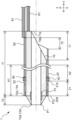
- FIG. 1 is a side view showing an example of a catheter according to an embodiment of the present invention.
- FIG. 2 is a cross-sectional view parallel to the longitudinal direction of the catheter shown in FIG. 1, showing a state in which the distal end of the second member is located at the first point.
- Figure 2 depicts a side view of the second member of the catheter shown in Figure 1 in its natural state;
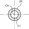
- 4 is a cross-sectional view taken along line IV-IV of the second member shown in FIG. 3.
- FIG. 4 shows a side view of a modification of the second member shown in FIG. 3.
- FIG. 6 shows a VI-VI sectional view of the second member shown in FIG. 5.
- FIG. FIG. 3 shows a VII-VII sectional view of the catheter shown in FIG. 2.
- FIG. 2 is a cross-sectional view parallel to the longitudinal direction of the catheter shown in FIG. 1, showing a state in which the distal end of the second member is located at the first point.
- Figure 2 depicts a side view of the second
- FIG. 2 is a cross-sectional view parallel to the longitudinal direction of the catheter shown in FIG. 1, showing a state in which the distal end of the second member is located at a second point.
- FIG. 7 shows a cross-sectional view parallel to the longitudinal direction of a catheter according to another embodiment of the present invention.
- One embodiment of a catheter of the present invention includes a first member having a distal end and a proximal end and a longitudinally extending lumen; and a second member that is movable in the longitudinal direction with respect to the first member, and the first member has a cylindrical main body and a thick member distal to the main body.
- the second member has a cylindrical distal tip portion that is smaller in thickness than the distal end of the main body portion, and the second member has a center point in the extending direction of the first member in a natural state where no external force is applied to the second member.
- the second member has a reduced section in the distal part of the second member in which the diameter of the smallest circle in contact with the surface of the second member in a cross section perpendicular to the longitudinal direction centered on the axis is smaller than the outer diameter of the main body part;
- the distal tip portion In a state in which the distal tip portion is disposed inside the reduced section, at least a portion of the outer surface of the distal tip portion is in contact with the inner surface of the second member in the reduced section, and the distal tip portion of the second member The end is located at a first point distal to the proximal end of the distal tip portion, where at least a portion of the outer surface of the distal tip portion contacts the inner surface of the second member in the reduced section.
- the minimum inner diameter of the distal tip portion is smaller than the minimum inner diameter of the distal tip portion when the distal end of the second member is located at a second point that is proximal to the first point. has.
- FIGS. 1 to 9. 1, 2, 8 and 9, a catheter 1 is shown having a first member 10 and a second member 20.
- the longitudinal direction of the first member 10 is indicated by x
- the radial direction is indicated by y.
- the radial direction y is a direction perpendicular to the longitudinal direction x, but only one direction perpendicular to the longitudinal direction x is shown here.
- the proximal side refers to the user's proximal side with respect to the extending direction of the first member 10
- the distal side refers to the side opposite to the proximal side, that is, the side to be treated.
- the distal part of each member refers to the distal half of each member
- the proximal part of each member refers to the proximal half of each member.
- FIG. 1 is a side view showing an example of a catheter 1 according to an embodiment of the present invention
- FIG. 2 is a cross-sectional view parallel to the longitudinal direction x of the catheter 1, in which the distal end 20d of the second member 20 is It represents the state of being located at the first point P1.
- the catheter 1 includes a first member 10 and a second member 20.
- the first member 10 has a distal end 10d and a proximal end 10p, and includes a lumen extending in the longitudinal direction x.
- the first member 10 has flexibility. Since the first member 10 has flexibility, when the first member 10 is inserted into the body, the first member 10 can be deformed along the shape of the body cavity. Moreover, it is preferable that the first member 10 has elasticity. Since the first member 10 has elasticity, even if the first member 10 is deformed to match the shape of the body cavity, the shape of the first member 10 can be maintained, and the inner cavity of the first member 10 can be made less likely to collapse.
- the first member 10 is, for example, a hollow body formed by arranging one or more wire rods in a predetermined pattern, or a hollow body coated with resin on at least one of the inner surface or outer surface of the hollow body. , resin tubes, and those connected in the longitudinal direction x.
- a hollow body in which wire rods are arranged in a predetermined pattern may have a network structure formed by intersecting or weaving wire rods, or by cutting out a metal tube or a tube made of a polymer material using a laser or the like.
- a cylindrical body having a cylindrical body, a coil around which a wire is wound, etc. are shown.
- the wire may be one or more single wires, or one or more twisted wires.
- the resin tube can be manufactured, for example, by extrusion molding.
- the first member 10 is preferably a resin tube. Since the first member 10 is a resin tube, it is easy to make the first member 10 excellent in both flexibility and elasticity.
- the first member 10 When the first member 10 is a resin tube, the first member 10 can be composed of a single layer or multiple layers.
- the first member 10 may have a single layer in the longitudinal direction x or a part in the circumferential direction, and may have a plurality of layers in other parts.
- Examples of materials constituting the first member 10 include polyolefin resins such as polyethylene and polypropylene, polyamide resins such as nylon, polyester resins such as PET, aromatic polyether ketone resins such as PEEK, and polyether polyamides. Synthetic resins such as polyurethane resins, polyurethane resins, polyimide resins, fluororesins such as PTFE, PFA, and ETFE, and metals such as stainless steel, carbon steel, and nickel-titanium alloys can be used. These may be used alone or in combination of two or more.
- the outer surface of the first member 10 has a layer containing at least one of a fluororesin and a polyolefin resin. Only a part of the outer surface of the first member 10 may be made of a fluororesin or a polyolefin resin, or the entire outer surface of the first member 10 may be made of a fluororesin or a polyolefin resin. good.
- the first member 10 may have a multilayer structure, and the material constituting the outermost layer may contain a fluorine-based resin. Examples include using at least one of a resin and a polyolefin resin, and applying a coating containing at least one of a fluororesin and a polyolefin resin to the outer surface of the first member 10.
- the inner surface of the first member 10 has a layer containing at least one of a fluororesin and a polyolefin resin. Only a part of the inner surface of the first member 10 may be made of a fluororesin or a polyolefin resin, or the entire inner surface of the first member 10 may be made of a fluororesin or a polyolefin resin. good.
- the first member 10 may have a multilayer structure, and the material constituting the innermost layer may contain a fluorine-based resin. Examples include using at least one of a resin and a polyolefin resin, and applying a coating containing at least one of a fluororesin and a polyolefin resin to the inner surface of the first member 10.
- the length of the first member 10 in the longitudinal direction x is the length of the second member 20 disposed outside the first member 10 in the longitudinal direction x, or the length of the article disposed in the inner cavity of the first member 10 in the longitudinal direction x.
- An appropriate length can be selected depending on the length etc.
- the length of the first member 10 in the longitudinal direction x can be, for example, 30 mm or more and 700 mm or less.
- the outer diameter of the first member 10 may be a size that allows the second member 20 disposed outside the first member 10 to slide, and an appropriate size can be selected as appropriate.
- the first member 10 includes a cylindrical main body 11 and a thickness that is distal to the main body 11 and is smaller than the thickness of the distal end 11d of the main body 11. It has a cylindrical tip portion 12.
- the thickness of the main body portion 11 may be different in at least one of the longitudinal direction x and the circumferential direction of the first member 10, but is preferably constant. Since the thickness of the main body portion 11 is constant in the longitudinal direction x and the circumferential direction, the rigidity of the main body portion 11 tends to be constant in the longitudinal direction Less likely to occur.
- the thickness of the main body portion 11 can be appropriately selected.
- the thickness of the main body portion 11 can be, for example, 0.01 mm or more and 1.0 mm or less.
- the inner diameter of the main body portion 11 can be appropriately selected depending on the size of the article placed in the inner cavity of the first member 10.
- the inner diameter of the main body portion 11 can be, for example, 0.4 mm or more, 0.8 mm or more, 1.2 mm or more, and 4.0 mm or less.
- the thickness of the distal end 12d of the distal tip portion 12 is preferably smaller than the thickness of the proximal end 12p of the distal tip portion 12. Since the thickness of the distal end 12d of the distal tip portion 12 is smaller than the thickness of the proximal end 12p of the distal tip portion 12, the rigidity of the distal side of the distal tip portion 12 is lower than that of the proximal side of the distal tip portion 12. The rigidity is lower than the rigidity, and the contact between the second member 20 and the distal tip portion 12 allows the minimum inner diameter of the distal tip portion 12 to be easily changed.
- the thickness of the proximal end 12p of the tip portion 12 can be appropriately selected depending on the thickness of the distal end 11d of the main body portion 11, etc.
- the thickness of the proximal end 12p of the tip portion 12 can be approximately the same as the thickness of the distal end 11d of the main body portion 11, and can be, for example, 0.01 mm or more and 1.0 mm or less.
- the distal tip portion 12 has a tapered shape that tapers from the proximal side to the distal side. Since the distal tip portion 12 is tapered, the second member 20 can easily slide on the distal tip portion 12 of the first member 10, and the second member 20 can be smoothly moved in the longitudinal direction x. It becomes easier.
- the outer diameter of the distal end 12d of the distal tip portion 12 is preferably smaller than the outer diameter of the proximal end 12p of the distal tip portion 12. Since the outer diameter of the distal end 12d of the distal tip portion 12 is smaller than the outer diameter of the proximal end 12p of the distal tip portion 12, the insertion property of the first member 10 can be improved, and the narrowed body cavity can be easily penetrated. The first member 10 can easily pass through.
- the first member 10 may be constructed by combining the parts that constitute the main body part 11 and the parts that constitute the distal tip part 12, but it is preferable that the main body part 11 and the distal tip part 12 are integrated. It is preferable. Since the main body part 11 and the distal tip part 12 are integrated, the second member 20 can easily move outside the first member 10 in the longitudinal direction x, and the distal tip part 12 can be moved away from the main body part 11. Separation can be made less likely to occur.
- the second member 20 is disposed outside the first member 10 and is movable in the longitudinal direction x with respect to the first member 10.
- FIG. 3 is a side view of the second member 20 in a natural state
- FIG. 4 is a sectional view perpendicular to the longitudinal direction x of the second member 20 shown in FIG. 3.
- 5 is a modification of the second member 20 shown in FIG. 3, and is a side view of the second member 20 in a natural state
- FIG. 6 is a side view of the second member 20 shown in FIG. 5 perpendicular to the longitudinal direction x.
- the second member 20 in a natural state where no external force is applied to the second member 20, the second member 20 is perpendicular to the longitudinal direction x centered on the central axis in the extending direction of the first member 10.
- the second member 20 has a reduced section 21 in the distal portion thereof, in which the diameter of the smallest circle C1 in contact with the surface of the second member 20 in a cross section is smaller than the outer diameter of the main body portion 11.
- the second member 20 may be, for example, a cylindrical body as shown in FIGS. 3 and 4, a wire rod as shown in FIGS. 5 and 6, or one or more wire rods arranged in a predetermined pattern. Examples include a hollow body formed by doing this, a hollow body coated with a resin on at least one of the inner surface or outer surface of the hollow body, and a hollow body formed by connecting these in the longitudinal direction x. As shown in FIGS. 5 and 6, when the second member 20 is made of a wire rod, the number of wire rods may be one or more.
- a hollow body in which wire rods are arranged in a predetermined pattern is a mesh formed by intersecting or weaving wire rods, or by cutting out a tube made of a metal tube or a polymeric material using a laser or the like.
- a cylindrical body having a structure, a coil wound with a wire, etc. are shown.
- the wire may be one or more single wires, or one or more twisted wires.
- Examples of materials constituting the second member 20 include metals such as stainless steel, carbon steel, and nickel-titanium alloys, polyolefin resins such as polyethylene and polypropylene, polyamide resins such as nylon, polyester resins such as PET, and PEEK. Synthetic resins such as aromatic polyetherketone resins, polyether polyamide resins, polyurethane resins, polyimide resins, and fluorine resins such as PTFE, PFA, and ETFE can be used. These may be used alone or in combination of two or more.
- the outer surface of the second member 20 is coated with a hydrophilic polymer. Since the outer surface of the second member 20 is coated with a hydrophilic polymer, the slipperiness of the outer surface of the second member 20 is improved, and the catheter 1 can be easily inserted.
- hydrophilic polymer examples include poly2-hydroxyethyl methacrylate, polyacrylamide, polyvinylpyrrolidone, and maleic anhydride copolymers such as methyl vinyl ether maleic anhydride copolymer.
- the length of the second member 20 in the longitudinal direction x can be appropriately selected depending on the length of the first member 10 in the longitudinal direction x.
- the length of the second member 20 in the longitudinal direction x can be 15 mm or more and 600 mm or less.
- the outer diameter of the second member 20 can be appropriately selected depending on the outer diameter of the first member 10 disposed inside the second member 20, etc.
- the outer diameter of the second member 20 can be 1.0 mm or more and 5.0 mm or less.
- the outer diameter of the second member 20 is preferably 1.0 mm or more and 2.5 mm or less.
- the thickness of the second member 20 can be selected to be an appropriate thickness, and can be, for example, 0.05 mm or more and 0.4 mm or less.
- the average thickness of the second member 20 can be, for example, 0.075 mm.
- FIG. 7 is a cross-sectional view of the catheter 1 perpendicular to the longitudinal direction x. As shown in FIGS. 1, 2, and 7, when the distal tip portion 12 is disposed inside the reduced section 21 of the second member 20, at least a portion of the outer surface of the distal tip portion 12 is reduced. It is in contact with the inner surface of the second member 20 in the section 21 .
- FIG. 8 is a cross-sectional view parallel to the longitudinal direction x of the catheter 1, showing a state in which the distal end 20d of the second member 20 is located at the second point P2.
- the distal end 20d of the second member 20 is distal to the proximal end 12p of the distal tip portion 12 and is contracted with at least a portion of the outer surface of the distal tip portion 12.
- the minimum inner diameter of the distal tip portion 12 in the state where the tip portion 12 is located at the first point P1 where it contacts the inner surface of the second member 20 in the section 21 is such that the distal end 20d of the second member 20 is closer to the first point P1 than the first point P1. is also smaller than the minimum inner diameter of the distal tip portion 12 when it is located at the second point P2 on the proximal side.
- the minimum inner diameter of the distal tip portion 12 when the distal end 20d of the second member 20 is located at the first point P1 is the same as when the distal end 20d of the second member 20 is located at the second point P2.
- the diameter of the distal tip portion 12 is smaller than the minimum inner diameter of the distal tip portion 12 in The inner diameter can be reduced.
- the catheter 1 with the distal end 20d of the second member 20 located at the first point P1 is transported to the treatment section. Since the distal end 20d of the second member 20 is located at the first point P1, the inner diameter of the distal tip portion 12 is in a small state. The small inner diameter of the distal tip portion 12 makes it difficult for the catheter 1 to come into contact with the wall of the body cavity and damage the wall of the body cavity when the catheter 1 is transported to the treatment section. Since it is less likely to get caught on the wall of the body, it is possible to improve its passage through the body cavity.
- the distal end 20d of the second member 20 is located closer to the proximal side than the first point P1, so that the distal end of the second member 20 20d is larger than the minimum inner diameter of the distal tip portion 12 when it is located at the first point P1.
- a medical device such as a balloon, stent, basket, needle, etc. is arranged in the inner cavity of the first member 10 and transported to a treatment section, the medical device can be easily protruded from the distal tip portion 12.
- the minimum inner diameter of the distal tip portion 12 is preferably located at the distal end 12d of the distal tip portion 12. That is, it is preferable that the portion of the distal tip portion 12 having the smallest inner diameter be the distal end 12d of the distal tip portion 12. Since the portion of the distal tip portion 12 with the smallest inner diameter is the distal end 12d of the distal tip portion 12, the outer diameter of the distal end of the catheter 1 is reduced, and the insertability of the catheter 1 can be improved.
- the smallest circle C1 in contact with the surface of the second member 20 in a cross section perpendicular to the longitudinal direction The diameter is preferably 98% or less, more preferably 95% or less, and even more preferably 93% or less of the maximum outer diameter of the main body portion 11.
- the lower limit of the ratio of the diameter of the smallest circle C1 in contact with the surface of the second member 20 and the maximum outer diameter of the main body portion 11 is not particularly limited, but may be, for example, 5% or more, 10% or more, or 15% or more. can do.
- a lubricious coating layer be provided between the first member 10 and the second member 20.
- a lubricant coating layer between the first member 10 and the second member 20.
- silicone fluororesin, polyolefin resin, and the like.
- silicone can be suitably used as the material constituting the lubricious coating layer.
- the minimum inner diameter of the distal tip portion 12 in a state where the distal end 20d of the second member 20 is located more distally than the proximal end 12p of the distal tip portion 12 is 30% or more of the inner diameter of the main body portion 11. It is preferably at least 35%, more preferably at least 40%.
- the minimum inner diameter of the distal tip portion 12 in a state where the distal end 20d of the second member 20 is located more distally than the proximal end 12p of the distal tip portion 12 is 70% of the inner diameter of the main body portion 11. It is preferably at most 65%, even more preferably at most 60%.
- the minimum inner diameter of the distal tip portion 12 is likely to be sufficiently small relative to the main body portion 11. . As a result, the distal tip portion 12 is less likely to come into contact with the wall of the body cavity, and the catheter 1 can be inserted easily.
- the minimum inner diameter of the distal tip portion 12 in a state where the distal end 20d of the second member 20 is located more distally than the proximal end 12p of the distal tip portion 12 can be selected to be an appropriate size. .
- the minimum inner diameter of the distal tip portion 12 in a state where the distal end 20d of the second member 20 is located more distally than the proximal end 12p of the distal tip portion 12 is, for example, 0.3 mm or more, 2.0 mm. It can be as follows.
- An appropriate size can be selected as appropriate.
- the minimum outer diameter of the distal tip portion 12 in a state in which the distal end 20d of the second member 20 is located more distally than the proximal end 12p of the distal tip portion 12 is, for example, 0.31 mm or more, 3. It can be set to 0 mm or less.
- the minimum inner diameter of the distal tip portion 12 in a state where the distal end 20d of the second member 20 is located closer to the proximal end 12p of the distal tip portion 12 is appropriate depending on the inner diameter of the main body portion 11, etc. You can choose the size you want.
- the minimum inner diameter of the distal tip portion 12 in a state where the distal end 20d of the second member 20 is located closer to the proximal side than the proximal end 12p of the distal tip portion 12 is approximately the same as the inner diameter of the main body portion 11. be able to.
- the minimum inner diameter of the distal tip portion 12 in a state where the distal end 20d of the second member 20 is located closer to the proximal side than the proximal end 12p of the distal tip portion 12 is, for example, 0.4 mm or more, 0.8 mm. Above, it can be set to 1.2 mm or more, and it can be set to 4.0 mm or less.
- the length in the longitudinal direction x of the distal tip portion 12 in a state where the distal end 20d of the second member 20 is located closer to the proximal end 12p of the distal tip portion 12 is appropriately set to an appropriate length. can be selected.
- the length in the longitudinal direction x of the distal tip portion 12 in a state where the distal end 20d of the second member 20 is located more proximally than the proximal end 12p of the distal tip portion 12 is, for example, 1 mm or more and 20 mm. It can be as follows.
- RX type rapid exchange type
- OGW type over-the-wire type
- the rigidity of the distal tip portion 12 in the direction perpendicular to the longitudinal direction x is preferably lower than the rigidity of the second member 20 in the direction perpendicular to the longitudinal direction x in the reduction section 21. Since the rigidity of the distal tip portion 12 is lower than the rigidity of the second member 20 in the reduced section 21, when the distal tip portion 12 is disposed inside the reduced section 21 of the second member 20, the distal tip portion 12 can be easily reduced in diameter by the reduction section 21.
- the rigidity of the main body portion 11 in the direction perpendicular to the longitudinal direction x is preferably higher than the rigidity of the second member 20 in the direction perpendicular to the longitudinal direction x in the reduced section 21. Since the rigidity of the main body portion 11 is higher than the rigidity of the second member 20 in the reduced section 21, the second member 20 is pulled toward the hand, and the distal end 20d of the second member 20 is moved proximal to the distal tip portion 12. When located on the proximal side of the end 12p, the reduced section 21 becomes easier to expand in diameter along the outer shape of the main body portion 11. As a result, the second member 20 can be easily moved toward the user's hand, and the operation of protruding the medical device from the distal tip portion 12 can be facilitated.
- the stiffness of the second member 20 in the direction perpendicular to the longitudinal direction x in the reduced section 21 is the same as or higher than the stiffness of the second member 20 in the direction perpendicular to the longitudinal direction x on the proximal side of the reduced section 21. It is also preferable that the temperature is also low. Since the stiffness of the second member 20 in the reduced section 21 is the same as or lower than the stiffness of the second member 20 on the proximal side of the reduced section 21, the reduced section 21 becomes easier to expand in diameter. , it is possible to smoothly pull the second member 20 toward the user's hand.
- the stiffness of the second member 20 in the direction perpendicular to the longitudinal direction x in the reduced section 21 may be lower than the stiffness of the second member 20 in the direction perpendicular to the longitudinal direction x on the proximal side of the reduced section 21. More preferred. Since the stiffness of the second member 20 in the reduced section 21 is lower than the stiffness of the second member 20 on the proximal side of the reduced section 21, the distal end 20d of the second member 20 is connected to the distal tip portion 12. When disposed on the distal side of the proximal end 12p, the reduced section 21 is easy to reduce in diameter, and the inner diameter of the distal tip portion 12 can be easily reduced in diameter.
- the length of the reduction section 21 is preferably longer than the length of the distal tip portion 12 in the longitudinal direction x. Since the length of the reduced section 21 is longer than the length of the distal tip section 12, the reduced section 21 can easily cover the distal tip section 12. Therefore, even if the diameter of the distal tip portion 12 is reduced by the reduced section 21 of the second member 20 and folds or wrinkles occur in the distal tip portion 12, the reduced section 21 covers the distal tip portion 12, so that the distal end of the catheter 1 The catheter 1 can easily have a smooth end surface, and is less likely to get caught on the wall of a body cavity.
- the length of the reduced section 21 is preferably 1.05 times or more, more preferably 1.1 times or more, and 1.15 times or more the length of the distal tip portion 12. It is even more preferable that there be.
- the lower limit of the ratio of the length of the reduced section 21 to the length of the distal tip section 12 within the above range, the entire distal tip section 12 can be easily covered by the reduced section 21.
- the upper limit of the ratio between the length of the reduced section 21 and the length of the distal tip portion 12 in the longitudinal direction x is not particularly limited, but may be, for example, 3 times or less, 2.5 times or less, or 2 times or less. .
- a region A1 extends 10 cm proximal from the distal end 11d of the main body 11 in the first member 10, and a region A1 extends 10 cm from the proximal end 21p of the reduced section 21 in the second member 20. It is preferable to have an X-ray opaque portion 40 in at least one of the regions A2 up to the front side. By having the X-ray opaque portion 40 in at least one of the regions A1 and A2, it becomes possible to visually confirm the position of the distal end of the catheter 1 using an X-ray imaging device.
- the X-ray opaque portion 40 is a portion containing an X-ray opaque substance.
- the X-ray opaque substance include at least one selected from the group consisting of lead, barium, iodine, tungsten, gold, platinum, iridium, stainless steel, titanium, cobalt-chromium alloy, and the like.
- the X-ray opaque portion 40 may include a portion formed from an X-ray opaque substance, or may be a portion formed by kneading an X-ray opaque substance into a material such as a synthetic resin. .
- the X-ray opaque portion 40 is preferably formed of an X-ray opaque marker containing an X-ray opaque substance. Since the X-ray opaque portion 40 is an X-ray opaque marker, it is possible to easily form the X-ray opaque portion 40 at a desired position with high accuracy in manufacturing the catheter 1.
- Examples of the shape of the X-ray opaque marker forming the X-ray opaque portion 40 include a cylindrical shape, a polygonal cylindrical shape, a C-shaped cross section with a notch in the tube, and a coil shape in which a wire is wound. Among these, it is preferable that the X-ray opaque marker has a cylindrical shape. Since the X-ray opaque marker has a cylindrical shape, the visibility of the X-ray opaque portion 40 by the X-ray imaging device can be improved.
- the number of X-ray opaque parts 40 arranged in the region A1 from the distal end 11d of the main body part 11 to the proximal side by 10 cm in the first member 10 may be one or more. good. Further, the number of X-ray opaque portions 40 arranged in the region A2 from the proximal end 21p of the reduced section 21 to the proximal side by 10 cm in the second member 20 may be one, or may be plural. It's okay.
- the X-ray opaque part 40 is a region A1 from the distal end 11d of the main body part 11 in the first member 10 to a proximal side of 10 cm and a region A1 from the proximal end 21p of the reduced section 21 in the second member 20 to a proximal side by 10 cm. It is preferable to have it in area A2. That is, it is preferable that the X-ray opaque portion 40 is disposed in both the area A1 and the area A2. By disposing the X-ray opaque portion 40 in both the region A1 and the region A2, the positions of the distal ends of both the first member 10 and the second member 20 can be confirmed by an X-ray imaging device. This can make the procedure easier to perform.
- the number of X-ray opaque parts 40 arranged in the region A1 from the distal end 11d of the main body part 11 to the proximal side by 10 cm in the first member 10 is the same as that in the second member 10.
- the number of X-ray opaque parts 40 is preferably greater than the number of X-ray opaque parts 40 arranged in the region A2 from the proximal end 21p of the reduced section 21 in 20 to the 10 cm proximal side. Since the number of X-ray opaque parts 40 disposed in area A1 is greater than the number of X-ray opaque parts 40 disposed in area A2, the position of the distal end of catheter 1 can be captured by X-ray imaging. Confirmation can be made easier depending on the device.
- a first shape memory member 51 is provided at least in the distal tip portion 12 and inward from the outer surface of the first member 10.
- the elasticity is higher than the elasticity of the distal tip portion 12, and in the natural state where no external force is applied to the first shape memory member 51, the elasticity is perpendicular to the longitudinal direction x centered on the central axis in the extending direction of the first shape memory member 51.
- the diameter of the smallest circle in contact with the surface of the first shape memory member 51 in the cross section is preferably larger than the smallest inner diameter of the distal tip portion 12.
- elasticity refers to the magnitude of strain at the elastic limit
- high elasticity means that even if a large strain is applied, the material returns to its original shape and has a large restoring force.
- the first shape memory member 51 has higher elasticity than the distal tip portion 12, and even if the first shape memory member 51 is deformed by applying an external force, the first shape memory member 51 will naturally deform when the external force applied to the first shape memory member 51 is removed. This allows the first shape memory member 51 to easily return to its original shape.
- the distal end 20d of the second member 20 is The diameter of the distal tip portion 12 becomes easier to expand due to the first shape memory member 51 as it moves more proximally than the distal end 12d. As a result, the distal tip portion 12 can be opened easily.
- the material constituting the first shape memory member 51 examples include stainless steels such as SUS304 and SUS316, shape memory alloys such as Ni-Ti alloys, shape memory resins, and the like.
- the material constituting the first shape memory member 51 is preferably a shape memory alloy, and more preferably a Ni-Ti alloy. Since the material constituting the first shape memory member 51 is a Ni-Ti alloy, the first shape memory member 51 has excellent shape memory properties and elasticity.
- the diameter of the circle is preferably 1.1 times or more, more preferably 1.2 times or more, and even more preferably 1.3 times or more the minimum inner diameter of the distal tip portion 12.
- the surface of the first shape memory member 51 in a cross section perpendicular to the longitudinal direction x centered on the central axis in the extending direction of the first member 10 The diameter of the smallest contacting circle is preferably 100 times or less, more preferably 90 times or less, and even more preferably 80 times or less than the minimum inner diameter of the distal tip portion 12.
- the first shape memory member 51 is provided over both the distal tip portion 12 and the main body portion 11. Since the first shape memory member 51 is provided in both the distal tip portion 12 and the main body portion 11, the external force can be removed from the first shape memory member 51 after applying an external force to the first shape memory member 51 to deform it. At this time, the first shape memory member 51 easily returns to its original shape, making it easier to expand the diameter of the distal tip portion 12.
- the second shape memory section 52 has a second shape memory section 52 in a natural state where no external force is applied to the second shape memory section 52.
- the diameter of the smallest circle in contact with the surface of the second shape memory section 52 in a cross section perpendicular to the longitudinal direction x centered on the central axis in the extending direction of the first member 10 of the shape memory section 52 is The diameter of the second member 20 is preferably smaller than the diameter of the smallest circle in contact with the surface of the second member 20 in a cross section perpendicular to the longitudinal direction x centered on the central axis in the extending direction.
- the second shape memory section 52 Even if the second shape memory section 52 is deformed by applying an external force to the second shape memory section 52, if the external force applied to the second shape memory section 52 is removed, the second shape memory section 52 will remain the same in its natural state. It easily returns to its shape. Since at least the reduced section 21 of the second member 20 has the second shape memory section 52, the second shape memory section 52 allows the center axis of the first member 10 in the natural state to be The diameter of the smallest circle in contact with the surface of the second member 20 in the cross section perpendicular to the longitudinal direction x tends to become smaller. Therefore, the diameter of the distal tip portion 12 can be easily reduced by the reduced section 21 of the second member 20.
- the second shape memory section 52 may be a member separate from the second member 20 provided at least in the reduced section 21 of the second member 20, or may be at least a part of the second member 20. good.
- the entire second member 20 may be the second shape memory section 52 .
- Examples of materials constituting the second shape memory portion 52 include stainless steels such as SUS304 and SUS316, shape memory alloys such as Ni-Ti alloys, shape memory resins, and the like.
- the material constituting the second shape memory portion 52 is preferably a shape memory alloy, and more preferably a Ni-Ti alloy. Since the material constituting the second shape memory section 52 is a Ni-Ti alloy, the second shape memory section 52 can have excellent shape memory properties and elasticity.
- Second shape memory in a cross section perpendicular to the longitudinal direction x centered on the central axis in the extending direction of the first member 10 of the second shape memory section 52 in a natural state where no external force is applied to the second shape memory section 52
- the diameter of the smallest circle in contact with the surface of the portion 52 is the diameter of the smallest circle in contact with the surface of the second member 20 in a cross section perpendicular to the longitudinal direction x centered on the central axis in the extending direction of the first member 10. It is preferably 99% or less, more preferably 97% or less, even more preferably 95% or less.
- the second shape memory section 52 in the natural state where no external force is applied to the second shape memory section 52 in a cross section perpendicular to the longitudinal direction
- the diameter of the smallest circle in contact with the surface of the shape memory portion 52 is the diameter of the smallest circle in contact with the surface of the second member 20 in a cross section perpendicular to the longitudinal direction x centered on the central axis in the extending direction of the first member 10.
- the second member 20 includes a lumen extending in the longitudinal direction x, and the first member 10 may be disposed in the lumen of the second member 20.
- the second member 20 is preferably a cylindrical body.
- the second member 20 When the second member 20 is a cylindrical body, the second member 20 can be composed of a single layer or multiple layers.
- the second member 20 may have a single layer in the longitudinal direction x or a part in the circumferential direction, and may have a plurality of layers in the other part.
- the catheter 1 further includes a first linear member 61, and the first linear member 61 is fixed to the proximal portion of the first member 10. is preferred. Since the catheter 1 includes the first linear member 61 fixed to the proximal portion of the first member 10, it becomes easier to push the first member 10 toward the treatment section. By pushing the first member 10 toward the treatment section, the distal end 20d of the second member 20 can be relatively moved proximally, and the diameter of the distal tip portion 12 can be expanded by the reduction section 21.
- the first linear member 61 is a long wire.
- the wire constituting the first linear member 61 may be a single wire or may be a stranded wire made of a plurality of single wires.
- the material constituting the first linear member 61 is preferably a metal such as stainless steel, titanium, nickel titanium alloy, cobalt chromium alloy, tungsten alloy, etc., and more preferably stainless steel or tungsten alloy. Since the material constituting the first linear member 61 is metal, the first linear member 61 can be made flexible and highly rigid, and the first linear member 61 can be made flexible and highly rigid even in a bent body cavity. You can make it easier to press.
- the length of the first linear member 61 in the longitudinal direction x may be any length that allows it to be operated from hand, and an appropriate length can be selected as appropriate.
- Examples of the cross-sectional shape of the first linear member 61 perpendicular to the longitudinal direction x include square, rectangular, trapezoidal, and circular shapes. Among these, it is preferable that the cross-sectional shape of the first linear member 61 perpendicular to the longitudinal direction x is circular. Since the cross-sectional shape of the first linear member 61 is circular, even if the first linear member 61 comes into contact with another object when pushing the first linear member 61, the first linear member 61 It can make things less likely to be damaged.
- the outer diameter of the first linear member 61 can be, for example, 0.2 mm or more and 1.0 mm or less.
- the outer diameter of the first linear member 61 refers to the diameter of the circumscribed circle of the cross-sectional shape of the first linear member 61.
- the first linear member 61 may be fixed to the proximal portion of the first member 10 by, for example, welding using a laser, welding, brazing, caulking, or using an adhesive such as acrylic, epoxy, or urethane. Examples include a method of joining by adhesion, a method of fixing with a heat shrink tube, and the like. Among these, it is preferable that the first linear member 61 is fixed to the proximal portion of the first member 10 by bonding with an adhesive. Since the first linear member 61 is fixed to the proximal portion of the first member 10 by adhesive bonding, the bonding strength between the first linear member 61 and the first member 10 can be easily increased. .
- a grip portion is provided on the proximal side of the first linear member 61.
- the material constituting the gripping portion include synthetic resins such as polyolefin resins such as polyethylene and polypropylene.
- the catheter 1 further includes a second linear member 62, and the second linear member 62 is fixed to the proximal portion of the second member 20. is preferred. Since the catheter 1 has the second linear member 62 fixed to the proximal portion of the second member 20, it becomes easier to pull the second member 20 toward the proximal side. By pulling the second member 20 toward the proximal side, the distal end 20d of the second member 20 can be moved toward the proximal side, and the diameter of the distal tip portion 12 can be expanded.
- the second linear member 62 is a long wire.
- the wire constituting the second linear member 62 may be a single wire or a stranded wire made of a plurality of single wires.
- the material constituting the second linear member 62 is preferably a metal such as stainless steel, titanium, nickel titanium alloy, cobalt chromium alloy, tungsten alloy, etc., and more preferably stainless steel or tungsten alloy. Since the material constituting the second linear member 62 is metal, the second linear member 62 can be flexible and have high rigidity, and the second linear member 62 can be used even in a bent body cavity. 62 becomes easier to draw.
- the length of the second linear member 62 in the longitudinal direction x may be a length that can be operated from hand or a length that can be inserted into the inner cavity of a cylindrical member 81, which will be described later. can be selected.
- Examples of the cross-sectional shape of the second linear member 62 perpendicular to the longitudinal direction x include square, rectangular, trapezoidal, and circular shapes. Among these, it is preferable that the cross-sectional shape of the second linear member 62 perpendicular to the longitudinal direction x is circular. Since the cross-sectional shape of the second linear member 62 is circular, even if the second linear member 62 comes into contact with another object when pulling the second linear member 62, the second linear member 62 Less likely to damage things.
- the outer diameter of the second linear member 62 can be, for example, 0.2 mm or more and 1.0 mm or less.
- the outer diameter of the second linear member 62 refers to the diameter of the circumscribed circle of the cross-sectional shape of the second linear member 62.
- the second linear member 62 may be fixed to the proximal portion of the second member 20 by, for example, welding using a laser, welding, brazing, caulking, or using an adhesive such as acrylic, epoxy, or urethane. Examples include a method of joining by adhesion, a method of fixing with a heat shrink tube, and the like. Among these, it is preferable that the second linear member 62 is fixed to the proximal portion of the second member 20 by bonding with an adhesive. Since the second linear member 62 is fixed to the proximal portion of the second member 20 by adhesive bonding, the bonding strength between the second linear member 62 and the second member 20 can be easily increased.
- a grip portion is provided on the proximal side of the second linear member 62.
- the material constituting the gripping portion include synthetic resins such as polyolefin resins such as polyethylene and polypropylene.
- the first member 10 has a proximal portion with a length in the radial direction y when observed from a direction perpendicular to the longitudinal direction x toward the proximal side.
- the first diameter-reduced region 71 may have a shorter diameter. Since the first member 10 has the first diameter-reduced region 71, the flexibility of the first member 10 is increased, and the first member 10 becomes easier to bend in accordance with the curved body cavity.
- the length of the first diameter-reduced region 71 in the longitudinal direction x is preferably 50% or less of the length of the first member 10, more preferably 40% or less, and still more preferably 30% or less. preferable.
- the rigidity of the first member 10 can be maintained and the insertability of the catheter 1 can be improved.
- the length of the first diameter-reduced region 71 in the longitudinal direction x is preferably 2% or more, more preferably 4% or more, and 6% or more of the length of the first member 10. is even more preferable.
- the lower limit of the ratio of the length of the first diameter-reduced region 71 to the length of the first member 10 in the above range the flexibility of the first member 10 is increased and the first member 10 is easily curved. can do.
- a second linear member 62 is provided on the proximal side of the second member 20, and the second linear member 62 is located at the proximal end of the first diameter-reduced region 71.
- it is fixed to the second member 20 on the distal side of 71p. Since the second linear member 62 is fixed to the second member 20 on the distal side of the proximal end 71p of the first diameter-reduced region 71, it is easy to pull the second linear member 62 toward the proximal side. This makes it easier to move the second member 20 in the longitudinal direction x.
- the catheter 1 further includes a cylindrical member 81 whose maximum outer diameter is smaller than the maximum outer diameter of the second member 20, and the distal portion of the cylindrical member 81 is connected to the first member 20.
- the second linear member 62 is fixed to the proximal portion of the reduced diameter region 71 and disposed in the inner cavity of the cylindrical member 81 .
- the cylindrical member 81 is a cylindrical member having an inner cavity, and has a maximum outer diameter smaller than the maximum outer diameter of the second member 20.
- the minimum outer diameter of the cylindrical member 81 may be smaller than the minimum outer diameter of the second member 20.
- Examples of the material constituting the cylindrical member 81 include the same synthetic resin and metal as the material constituting the first member 10.
- the material constituting the cylindrical member 81 may be a different material from the material constituting the first member 10, but is preferably the same material as the material constituting the first member 10. Since the material constituting the cylindrical member 81 is the same material as the material constituting the first member 10, the strength of fixing the cylindrical member 81 and the first diameter-reduced region 71 can be easily increased.
- the length in the longitudinal direction x of the cylindrical member 81 can be selected appropriately depending on the length in the longitudinal direction x of the second linear member 62 disposed in the inner cavity of the cylindrical member 81. .
- the length of the cylindrical member 81 in the longitudinal direction x can be, for example, 100 mm or more and 2400 mm or less.
- the outer diameter of the cylindrical member 81 can be appropriately selected, and can be, for example, 0.6 mm or more and 3.0 mm or less. Among these, the outer diameter of the cylindrical member 81 is preferably 0.6 mm or more and 1.0 mm or less. By setting the outer diameter of the cylindrical member 81 within the above range, the outer diameter of the cylindrical member 81 is difficult to increase, and the outer diameter of the catheter 1 is prevented from increasing in accordance with the outer diameter of the cylindrical member 81. can do.
- the inner diameter of the cylindrical member 81 can be, for example, 0.3 mm or more and 2.5 mm or less. Among these, the inner diameter of the cylindrical member 81 is preferably 0.5 mm or more and 0.9 mm or less. By setting the inner diameter of the cylindrical member 81 within the above range, it is possible to easily insert the second linear member 62 into the inner cavity of the cylindrical member 81, and to keep the outer diameter of the cylindrical member 81 small. becomes.
- the outer surface of the cylindrical member 81 may be coated with a lubricant coating.
- a lubricant coating fluororesin such as PTFE, PFA, ETFE, etc. can be used.
- the lubricating coating on the outer surface of the cylindrical member 81 increases the slipperiness of the outer surface of the cylindrical member 81. As a result, the insertability of the catheter 1 can be improved.
- a position marker may be provided on the cylindrical member 81 in order to confirm the length of the catheter 1 inserted into the body cavity.
- methods for providing position markers on the cylindrical member 81 include arranging markers on the cylindrical member 81 and partially peeling off a coating applied to the outer surface of the cylindrical member 81. .
- Examples of methods for fixing the distal part of the cylindrical member 81 to the proximal part of the first diameter-reduced region 71 include laser welding, welding, brazing, caulking, acrylic, epoxy, urethane, etc.
- a method of bonding by bonding with an adhesive or the like can be mentioned.
- the second member 20 has a proximal portion that has a length in the radial direction y when observed from a direction perpendicular to the longitudinal direction x.
- the second diameter-reduced region 72 is shortened. Since the second member 20 has the second diameter-reduced region 72, the flexibility of the second member 20 can be increased, and the second member 20 can be easily bent along a curved body cavity. I can do it.
- the length of the second reduced diameter region 72 in the longitudinal direction x is preferably 50% or less of the length of the second member 20, more preferably 40% or less, and still more preferably 30% or less. preferable.
- the rigidity of the second member 20 can be maintained and the insertability of the catheter 1 can be increased.
- the length of the second diameter-reduced region 72 in the longitudinal direction x is preferably 2% or more, more preferably 4% or more, and 6% or more of the length of the second member 20. is even more preferable.
- the lower limit value of the ratio of the length of the second diameter-reduced region 72 to the length of the second member 20 in the above range the flexibility of the second member 20 is increased, and the second member 20 can be easily bent. I can do it.
- the catheter 1 preferably further includes a hub 110 at the proximal end of the first member 10 or the cylindrical member 81.
- the hub 110 has a port inside thereof that communicates with the inner cavity of the first member 10 or the cylindrical member 81, and when introducing a member or fluid into the inner cavity of the first member 10 or the cylindrical member 81. This is the member used.
- the hub 110 may be directly connected to the proximal end 10p of the first member 10 or the proximal end of the cylindrical member 81, or indirectly connected to the proximal end 10p of the first member 10 or the cylindrical member 81 via another member. It may be connected to the proximal end of the shaped member 81.
- FIG. 9 is a sectional view parallel to the longitudinal direction x of a catheter 1 according to another embodiment of the present invention.
- a shaft 90 is disposed in the inner cavity of the first member 10 in a movable state with respect to the first member 10, and a shaft 90 is provided at a distal portion of the shaft 90 and is disposed in a radial direction.
- An expansion member 100 that expands in y.
- the shaft 90 can be configured to have a lumen extending in the longitudinal direction x. Note that the inner cavity of the shaft 90 can be used as an insertion path for a guide wire 120, etc., as shown in FIG.
- Examples of the material constituting the shaft 90 include the same synthetic resin and metal as the material constituting the first member 10.
- the material forming the shaft 90 may be the same material as the material forming the first member 10, or may be a different material from the material forming the first member 10.
- expansion member 100 for example, a balloon or a stent can be used.
- the balloon is made of resin.
- resins constituting the balloon include polyamide resins, polyester resins, polyurethane resins, polyolefin resins, vinyl chloride resins, silicone resins, and natural rubber. These may be used alone or in combination of two or more.
- polyamide resins, polyester resins, and polyurethane resins are preferably used as resins constituting the balloon. From the viewpoint of making the balloon thinner and more flexible, elastomer resin can be used.
- a stent is an expandable structure made of a network structure such as a mesh, and includes a plurality of struts. Stents, for example, can be formed from a pattern of interconnected structural elements that expand and contract circumferentially and axially.
- a stent is a coil made of a single linear metal or polymeric material, a metal tube or a polymeric material tube cut out using a laser, etc., or a stent assembled by welding linear parts. , one constructed by weaving a plurality of linear metals, etc.
- the stent is preferably constructed from a shape memory alloy or shape memory resin. Since the stent is made of shape memory alloy or shape memory resin, the stent can be expanded smoothly.
- the stent may be made of, for example, stainless steel such as SUS304 or SUS316, platinum, nickel, cobalt, chromium, titanium, tungsten, aluminum, gold, silver, Ni-Ti alloy, Co-Cr alloy, or the like.
- the stent may be a self-expanding stent or a balloon expandable stent.
- the catheter 1 may be configured to further include a control mechanism that suppresses movement of the shaft 90 in the longitudinal direction x in the inner cavity of the first member 10. Since the catheter 1 includes the control mechanism, the control mechanism enables the catheter 1 to be transported to the treatment section while suppressing movement of the shaft 90 in the longitudinal direction x in the inner lumen of the first member 10. Therefore, the catheter 1 can be easily transported to the treatment section.
- the control mechanism may include, for example, a mode in which the first member 10 is provided with a gripping member that can grip the shaft 90. Since the first member 10 is provided with the gripping member, the shaft 90 can be gripped by the gripping member, and movement of the shaft 90 in the longitudinal direction x in the inner cavity of the first member 10 can be temporarily suppressed. . Then, by removing the shaft 90 from the gripping member, the shaft 90 can be returned to a movable state with respect to the first member 10.
- the gripping member include a rubber member provided with a slit for gripping the shaft 90, a clip made of synthetic resin, and the like.
- the expansion member 100 is preferably a balloon or stent with a coating layer formed on its outer surface. Since the expansion member 100 is a balloon or stent with a coating layer formed on the outer surface, the outer surface of the expansion member 100 has increased slipperiness, and the expansion member 100 can be easily released from the distal tip portion 12.
- the coating layer can be formed by applying a coating agent to the outer surface of the balloon or stent.
- the coating layer may be formed only on a part of the outer surface of the balloon or stent, or may be formed on the entire outer surface of the balloon or stent.
- the coating layer may contain a lubricating coating agent or a physiologically active agent.
- lubricating coating agents examples include silicone coating agents such as silicone and polydimethylsiloxane, sodium (meth)acrylate, butyl (meth)acrylate, methyl (meth)acrylate, ethyl (meth)acrylate, and propyl (meth)acrylate.
- silicone coating agents such as acrylate, octyl (meth)acrylate, 2,2,2-trifluoroethyl methacrylate, fluorine coating agents such as polytetrafluoroethylene, hydrophilic coating agents such as polyvinylpyrrolidone, hyaluronic acid, polyethylene glycol, etc. can be mentioned.
- physiologically active drugs include paclitaxel, docetaxel, sirolimus, temsirolimus, everolimus, zotarolimus, biolimus A9, cilostazol, cyclosporine, NF- ⁇ B decoy oligo, and the like.
- Physiologically active agents may be used alone or in combination.
- the balloon or stent may be coated with the physiologically active substance alone, or an additive may be used in combination as appropriate.
- the coating layer preferably contains a physiologically active drug. Since the coating layer of the balloon or stent contains a physiologically active agent, the efficiency of treatment can be increased by placing the balloon or stent in the treatment area using the catheter 1.
- the catheter 1 may further include a controller for the catheter 1, a device used together with the catheter 1, a hub, etc.
- the catheter 1 may have a locking mechanism for fixing a controller, a device, a hub, etc. to the proximal end thereof.
- the length of the catheter 1 in the longitudinal direction x can be appropriately selected.
- the length of the catheter 1 in the longitudinal direction x can be, for example, 200 mm or more and 2500 mm or less.
- First member 10d Distal end of first member 10p: Proximal end of first member 11: Main body 11d: Distal end of main body 12: Distal tip 12d: Distal of distal tip Proximal end 12p: Proximal end of the distal tip portion 20: Second member 20d: Distal end of the second member 21: Reduction section 21p: Proximal end of the reduction section 40: X-ray opaque portion 51: First shape memory Member 52: Second shape memory portion 61: First linear member 62: Second linear member 71: First reduced diameter region 71p: Proximal end of first reduced diameter region 72: Second reduced diameter region 81: Cylinder shaped member 90: shaft 100: expansion member 110: hub 120: guide wire x: longitudinal direction y: radial direction C1: second member in a cross section perpendicular to the longitudinal direction centered on the central axis in the extending direction of the first member The smallest circle in contact with the surface of Area up to 10cm proximal
Landscapes
- Health & Medical Sciences (AREA)
- Life Sciences & Earth Sciences (AREA)
- Biophysics (AREA)
- Pulmonology (AREA)
- Engineering & Computer Science (AREA)
- Anesthesiology (AREA)
- Biomedical Technology (AREA)
- Heart & Thoracic Surgery (AREA)
- Hematology (AREA)
- Animal Behavior & Ethology (AREA)
- General Health & Medical Sciences (AREA)
- Public Health (AREA)
- Veterinary Medicine (AREA)
- Media Introduction/Drainage Providing Device (AREA)
Priority Applications (2)
| Application Number | Priority Date | Filing Date | Title |
|---|---|---|---|
| CN202380030411.2A CN118973646A (zh) | 2022-03-29 | 2023-03-09 | 导管 |
| JP2024511647A JPWO2023189377A1 (https=) | 2022-03-29 | 2023-03-09 |
Applications Claiming Priority (2)
| Application Number | Priority Date | Filing Date | Title |
|---|---|---|---|
| JP2022054635 | 2022-03-29 | ||
| JP2022-054635 | 2022-03-29 |
Publications (1)
| Publication Number | Publication Date |
|---|---|
| WO2023189377A1 true WO2023189377A1 (ja) | 2023-10-05 |
Family
ID=88200654
Family Applications (1)
| Application Number | Title | Priority Date | Filing Date |
|---|---|---|---|
| PCT/JP2023/009133 Ceased WO2023189377A1 (ja) | 2022-03-29 | 2023-03-09 | カテーテル |
Country Status (3)
| Country | Link |
|---|---|
| JP (1) | JPWO2023189377A1 (https=) |
| CN (1) | CN118973646A (https=) |
| WO (1) | WO2023189377A1 (https=) |
Citations (4)
| Publication number | Priority date | Publication date | Assignee | Title |
|---|---|---|---|---|
| US5447503A (en) * | 1991-08-14 | 1995-09-05 | Cordis Corporation | Guiding catheter tip having a tapered tip with an expandable lumen |
| JP2010057770A (ja) * | 2008-09-05 | 2010-03-18 | Nipro Corp | カテーテル組立体 |
| JP2015526159A (ja) * | 2012-07-17 | 2015-09-10 | ボストン サイエンティフィック サイムド,インコーポレイテッドBoston Scientific Scimed,Inc. | ガイド拡張カテーテル |
| JP2019154903A (ja) * | 2018-03-15 | 2019-09-19 | テルモ株式会社 | カテーテル組立体 |
-
2023
- 2023-03-09 JP JP2024511647A patent/JPWO2023189377A1/ja active Pending
- 2023-03-09 WO PCT/JP2023/009133 patent/WO2023189377A1/ja not_active Ceased
- 2023-03-09 CN CN202380030411.2A patent/CN118973646A/zh active Pending
Patent Citations (4)
| Publication number | Priority date | Publication date | Assignee | Title |
|---|---|---|---|---|
| US5447503A (en) * | 1991-08-14 | 1995-09-05 | Cordis Corporation | Guiding catheter tip having a tapered tip with an expandable lumen |
| JP2010057770A (ja) * | 2008-09-05 | 2010-03-18 | Nipro Corp | カテーテル組立体 |
| JP2015526159A (ja) * | 2012-07-17 | 2015-09-10 | ボストン サイエンティフィック サイムド,インコーポレイテッドBoston Scientific Scimed,Inc. | ガイド拡張カテーテル |
| JP2019154903A (ja) * | 2018-03-15 | 2019-09-19 | テルモ株式会社 | カテーテル組立体 |
Also Published As
| Publication number | Publication date |
|---|---|
| CN118973646A (zh) | 2024-11-15 |
| JPWO2023189377A1 (https=) | 2023-10-05 |
Similar Documents
| Publication | Publication Date | Title |
|---|---|---|
| US11712544B2 (en) | Guide extension catheter | |
| JP4547374B2 (ja) | アンバランスな補強部材を含む医療用装置及びその製造方法 | |
| EP4008388B1 (en) | Catheter including radiopaque expandable member | |
| JP5728779B2 (ja) | 血管内止血カテーテル | |
| JP2015525636A (ja) | 拡張型ガイドエクステンションカテーテル | |
| EP4039315A1 (en) | Guide extension catheter | |
| JP2008508936A (ja) | 管内ステント組立体およびこの定置方法 | |
| JP2018187229A (ja) | 医療用長尺体 | |
| JP7524080B2 (ja) | 延長カテーテル、及びその製造方法 | |
| JP2013223663A (ja) | バルーンカテーテル用保護スリーブ、バルーンカテーテルシステムおよびステントデリバリーシステム | |
| JP2006218070A (ja) | カテーテル | |
| WO2023189377A1 (ja) | カテーテル | |
| WO2023189378A1 (ja) | カテーテル | |
| JP2023147080A (ja) | カテーテル | |
| JP2023147081A (ja) | カテーテル | |
| JP2025051095A (ja) | カテーテル | |
| WO2023189376A1 (ja) | カテーテル | |
| JP2025051096A (ja) | カテーテル | |
| WO2025069714A1 (ja) | カテーテル | |
| JP5799488B2 (ja) | 血管内薬剤溶出カテーテル | |
| US20250010031A1 (en) | Catheter | |
| WO2025204430A1 (ja) | 延長カテーテル | |
| JP2023130234A (ja) | 医療用管状体搬送装置の製造方法 | |
| WO2025187632A1 (ja) | 延長カテーテル | |
| WO2022154118A1 (ja) | カテーテルおよびカテーテル組立体 |
Legal Events
| Date | Code | Title | Description |
|---|---|---|---|
| 121 | Ep: the epo has been informed by wipo that ep was designated in this application |
Ref document number: 23779403 Country of ref document: EP Kind code of ref document: A1 |
|
| ENP | Entry into the national phase |
Ref document number: 2024511647 Country of ref document: JP Kind code of ref document: A |
|
| WWE | Wipo information: entry into national phase |
Ref document number: 202380030411.2 Country of ref document: CN |
|
| NENP | Non-entry into the national phase |
Ref country code: DE |
|
| 122 | Ep: pct application non-entry in european phase |
Ref document number: 23779403 Country of ref document: EP Kind code of ref document: A1 |