WO2023189352A1 - 異常判定装置および異常判定方法 - Google Patents
異常判定装置および異常判定方法 Download PDFInfo
- Publication number
- WO2023189352A1 WO2023189352A1 PCT/JP2023/009048 JP2023009048W WO2023189352A1 WO 2023189352 A1 WO2023189352 A1 WO 2023189352A1 JP 2023009048 W JP2023009048 W JP 2023009048W WO 2023189352 A1 WO2023189352 A1 WO 2023189352A1
- Authority
- WO
- WIPO (PCT)
- Prior art keywords
- evaluation value
- machine
- abnormality
- series
- calculated
- Prior art date
- Legal status (The legal status is an assumption and is not a legal conclusion. Google has not performed a legal analysis and makes no representation as to the accuracy of the status listed.)
- Ceased
Links
Images

Classifications
-
- B—PERFORMING OPERATIONS; TRANSPORTING
- B23—MACHINE TOOLS; METAL-WORKING NOT OTHERWISE PROVIDED FOR
- B23Q—DETAILS, COMPONENTS, OR ACCESSORIES FOR MACHINE TOOLS, e.g. ARRANGEMENTS FOR COPYING OR CONTROLLING; MACHINE TOOLS IN GENERAL CHARACTERISED BY THE CONSTRUCTION OF PARTICULAR DETAILS OR COMPONENTS; COMBINATIONS OR ASSOCIATIONS OF METAL-WORKING MACHINES, NOT DIRECTED TO A PARTICULAR RESULT
- B23Q17/00—Arrangements for observing, indicating or measuring on machine tools
-
- G—PHYSICS
- G05—CONTROLLING; REGULATING
- G05B—CONTROL OR REGULATING SYSTEMS IN GENERAL; FUNCTIONAL ELEMENTS OF SUCH SYSTEMS; MONITORING OR TESTING ARRANGEMENTS FOR SUCH SYSTEMS OR ELEMENTS
- G05B19/00—Program-control systems
- G05B19/02—Program-control systems electric
- G05B19/18—Numerical control [NC], i.e. automatically operating machines, in particular machine tools, e.g. in a manufacturing environment, so as to execute positioning, movement or co-ordinated operations by means of program data in numerical form
Definitions
- the present disclosure relates to an abnormality determining device and an abnormality determining method for determining abnormalities in machines including machine tools and processing machines.
- Patent Document 1 discloses an abnormality detection device for a machine tool.
- the abnormality detection device compares a preset normal range using the evaluation value during normal operation of the machine tool with the evaluation value during operation of the machine tool, and detects when the evaluation value during operation deviates from the normal range.
- Sometimes the machine tool is determined to be abnormal.
- the evaluation value is obtained by quantifying the waveform change of a target signal, which is a signal during a specific period during operation of the machine tool, among the signals output from the sensor.
- the abnormality detection device usually determines an abnormality in the machine tool by using a period in which the waveform is in a steady state as a specific period. Therefore, with the abnormality detection device, it may be difficult to detect an abnormality in the machine tool in an operating state where a transient phenomenon occurs in the waveform of the target signal (for example, immediately after the start of a series of operations of the machine tool).
- An object of the present disclosure is to provide an abnormality determination device and an abnormality determination method that can determine the abnormality of a machine regardless of its operating state.
- An abnormality determination device includes: an acquisition unit that acquires a signal corresponding to the operation of a machine including a machine tool and a processing machine that can repeatedly execute a series of operations; a calculation unit that calculates an evaluation value of the entire series of motions based on the signal acquired during a motion period that is set according to the length of the series of motions; a determination unit that determines whether or not the machine tool is abnormal based on the calculated evaluation value; The determination unit determines that the machine is abnormal when the calculated evaluation value is larger than a threshold value.
- An abnormality determination method includes: Acquires signals corresponding to the operation of machines, including machine tools and processing machines that can repeat a series of operations, calculating an evaluation value for the entire series of motions based on the signal acquired during a motion period set according to the length of the series of motions; When the calculated evaluation value is larger than a threshold value, it is determined that the machine is abnormal.
- the abnormality determination device of the above aspect it is possible to realize an abnormality determination device that can determine the abnormality of a machine regardless of the operating state.
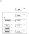
- FIG. 1 is a block diagram showing an abnormality determination device according to an embodiment of the present disclosure.
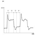
- the graph which shows an example of the waveform of the signal output from the sensor which detects the signal of a machine.
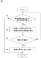
- 2 is a flowchart for explaining an abnormality determination process performed by the abnormality determination apparatus of FIG. 1.
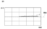
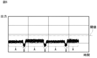
- FIG. 2 is a graph showing an example of an evaluation value of the entire series of operations calculated by the abnormality determination device of FIG. 1 based on a signal output from a sensor that detects a signal of a normal machine.
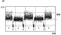
- 2 is a graph showing an example of an evaluation value of the entire series of operations calculated by the abnormality determination device of FIG. 1 based on a signal output from a sensor that detects an abnormal machine signal.
- the graph which shows an example of the evaluation value calculated based on the signal output from the sensor which detects the signal of a normal machine by the conventional method.
- the graph which shows an example of the evaluation value calculated based on the signal output from the sensor which detects the signal of an abnormal machine by the conventional method.
- an abnormality determination device 1 includes an acquisition unit 10, a calculation unit 20, and a determination unit 30, and is a machine 100 that can repeatedly execute a series of operations as one cycle. It is configured to perform abnormality determination.
- the machine 100 includes, for example, a machine tool that creates a workpiece into a desired shape, and a processing machine that processes a material into a desired shape using a machine tool or the like.
- the abnormality determination device 1 includes a calculation control section 40 and an output section 50.
- the abnormality determination device 1 includes, for example, a CPU 2, a storage device 3, and a communication device 4.
- Each of the acquisition unit 10, the calculation unit 20, the determination unit 30, and the calculation control unit 40 is a function realized by, for example, the CPU 2 executing a predetermined program.
- the storage device 3 is composed of, for example, a ROM and a RAM, and stores programs and the like necessary for executing abnormality determination.
- the communication device 4 is configured to be capable of wireless or wired communication with an external device (not shown).
- the acquisition unit 10 is configured to acquire a signal corresponding to the operation of the machine 100, for example via the communication device 4.
- Signals corresponding to the operation of the machine 100 include, for example, a signal output from a sensor that detects a signal from the machine 100, a signal output from a sensor that detects a current supplied to the machine 100, and a signal that drives the machine 100. This includes the signal output from the encoder attached to the motor.
- FIG. 2 shows an example of a waveform of a signal output from a sensor that detects a signal of the machine 100 when the machine 100 uses a drill to make a hole in a metal workpiece.
- a transient phenomenon occurs in which the waveform of the acquired signal temporarily increases due to switching of the drive state of the drill or the like.
- the waveform of the acquired signal is in a steady state.
- (1) to (4) in FIG. 2 show the following operating states. (1) The operating state in which the drill approaches and contacts the workpiece while it is being driven. (2) An operating state in which the drill contacts the workpiece and then moves toward the inside of the workpiece to a predetermined position. (3) The operating state from when the drill reaches the predetermined position until it stops. (4) An operating state in which the drill is stopped and away from the workpiece.
- the calculation unit 20 calculates an evaluation value of the entire series of operations of the machine 100 (hereinafter referred to as the evaluation value) based on the signal acquired by the acquisition unit 10 during the operation period set according to the length of the series of operations of the machine 100. .)".
- the evaluation value is, for example, an average value or an effective value calculated from Equation 1 below.
- x i is the measured value of the sensor acquired in each operation constituting the series of operations
- n is the number of operations included in the series of operations.
- the average value is a value that is the center of gravity of the entire data, and is calculated by adding up the sensor measurement values acquired in each motion that makes up the series of motions and dividing by the number of motions that make up the series of motions.
- the effective value is a value that indicates the same power consumption when all alternating current voltages and currents are replaced with direct current voltages and currents, assuming how many volts and how many amperes of current are respectively replaced. be.
- the determination unit 30 is configured to determine whether or not the machine 100 is abnormal based on the evaluation value calculated by the calculation unit 20. Specifically, the determination unit 30 determines that the machine 100 is abnormal when the calculated evaluation value deviates from the normal range. Whether or not the calculated evaluation value deviates from the normal range is determined by, for example, whether the calculated evaluation value is larger than a threshold value.
- the threshold value is set, for example, based on a pre-calculated normal evaluation value, or based on a pre-calculated normal evaluation value and a pre-calculated abnormal evaluation value.
- the determination unit 30 sets the 3 sigma value of the normal evaluation value or any value (for example, an intermediate value) between the normal evaluation value and the abnormal evaluation value as the threshold value.
- the normal evaluation value is the evaluation value when the machine 100 executes a series of operations and no abnormality occurs in the machine 100
- the abnormality evaluation value is the evaluation value when the machine 100 executes a series of operations and no abnormality occurs in the machine 100. This is the evaluation value when it occurs.
- whether or not an abnormality has occurred in the machine 100 is determined, for example, by visual inspection by the user.
- the calculation control unit 40 is configured to cause the calculation unit 20 to calculate the evaluation value for each set operation period after the series of operations of the machine 100 is started. For example, the calculation control unit 40 outputs a calculation signal that causes the calculation unit 20 to calculate the evaluation value at an arbitrary timing after the machine 100 starts a series of operations. The calculated signal is repeatedly output, for example, until the machine 100 stops or until it is determined that the machine 100 is abnormal.
- the output unit 50 is configured to output the abnormality determination result determined by the determination unit 30 to the user, for example via the communication device 4.
- abnormality determination process An example of the abnormality determination process performed by the abnormality determination device 1 will be described with reference to FIG. 3. Here, a case will be described in which whether or not the calculated evaluation deviates from the normal range is determined based on whether the calculated evaluation value is larger than a threshold value.
- the abnormality determination process is performed, for example, by the CPU 2 executing a predetermined program.
- the abnormality determination device 1 determines whether the acquisition unit 10 can acquire signals from the machine 100 over the entire operation period (step S1 ).
- the abnormality determination process ends.
- the calculation unit 20 calculates an evaluation value for the entire series of operations based on the acquired signals (step S2).
- the determination unit 30 determines whether the calculated evaluation value is larger than the threshold (step S3). If it is determined that the calculated evaluation value is larger than the threshold value, the determination unit 30 determines that the machine 100 is abnormal (step S4), and the output unit 50 outputs the determination result to the user and indicates that the machine 100 is abnormal. The determination process ends.
- step S1 If it is determined that the calculated evaluation value is not larger than the threshold value, the process returns to step S1, and it is determined whether the acquisition unit 10 has acquired the signal from the machine 100 over the entire operation period.
- the abnormality determination device 1 can exhibit the following effects.
- 4 and 5 are examples of evaluation values calculated by the calculation unit 20 of the abnormality determination device 1.
- FIGS. 6 and 7 are examples of evaluation values calculated by the conventional method. In FIGS. 6 and 7, among the output signals, a signal whose waveform is in a steady state is extracted, and an evaluation value is calculated each time the signal is output. That is, conventionally, the evaluation value group B in FIGS. 6 and 7 is not calculated, and the abnormality determination of the machine 100 is performed using only the evaluation value group A in FIGS. 6 and 7.
- the abnormality determination device 1 includes an acquisition section 10, a calculation section 20, and a determination section 30.
- the acquisition unit 10 acquires a signal corresponding to the operation of the machine 100 that can repeatedly execute a series of operations.
- the calculation unit 20 calculates an evaluation value for the entire series of operations based on signals acquired during an operation period that is set according to the length of the series of operations of the machine 100.
- the determination unit 30 determines whether or not the machine 100 is abnormal based on the calculated evaluation value. When the calculated evaluation value deviates from the normal range (for example, when the calculated evaluation value is larger than a threshold value), it is determined that the machine 100 is abnormal. That is, as shown in FIGS.
- the abnormality determination device 1 calculates the evaluation value C of the entire series of operations without cutting out the signal.
- the machine 100 can be constantly monitored without being affected by transient phenomena, so it is possible to realize an abnormality determination device 1 that can determine abnormalities in the machine 100 regardless of the operating state.
- the abnormality determination device 1 can arbitrarily adopt one or more of the following configurations. In other words, any one or more of the following configurations can be arbitrarily deleted if included in the above embodiment, and can be arbitrarily added if not included in the above embodiment. can. By employing such a configuration, it is possible to realize an abnormality determination device 1 that can more reliably determine abnormalities in the machine 100 regardless of the operating state.
- the determination unit 30 determines that the machine 100 is abnormal when the calculated evaluation value is larger than the threshold value.
- the determination unit 30 sets a threshold value based on a pre-calculated normal evaluation value, or based on a pre-calculated normal evaluation value and a pre-calculated abnormality evaluation value.
- the determination unit 30 sets the 3 sigma value of the normal evaluation value as a threshold value.
- the determination unit 30 sets an arbitrary value between the normal evaluation value and the abnormal evaluation value as a threshold value.
- An abnormality determination method acquires a signal corresponding to the operation of a machine 100 including a machine tool and a processing machine that can repeatedly execute a series of operations, and an operation period that is set according to the length of the series of operations.
- An evaluation value of the entire series of operations is calculated based on the signals acquired in , and when the calculated evaluation value is larger than a threshold value, it is determined that the machine 100 is abnormal.
- the machine 100 can be constantly monitored without being affected by transient phenomena, so it is possible to determine whether there is an abnormality in the machine 100 regardless of the operating state.
- the abnormality determination device 1 can also be configured as follows.
- the determination unit 30 may determine the range of evaluation values for abnormality determination based on the pre-calculated normality evaluation value and the pre-calculated abnormality evaluation value. With such a configuration, for example, the frequency of determination results output from the output unit 50 to the user can be reduced.
- the calculation control unit 40 can be omitted.
- the threshold value is not limited to being set based on the normal evaluation value and the abnormal evaluation value.
- the threshold value may be set by the operator manually inputting the threshold value.
- the abnormality determination device 1 includes: an acquisition unit 10 configured to acquire a signal according to the operation of a machine including a machine tool and a processing machine that can repeatedly execute a series of operations; a calculation unit 20 configured to calculate an evaluation value of the entire series of motions based on the signal acquired during a motion period set according to the length of the series of motions; a determination unit 30 configured to determine whether or not the machine is abnormal based on the calculated evaluation value; The determination unit 30 determines that the machine is abnormal when the calculated evaluation value deviates from a normal range.
- the abnormality determination device 1 includes: The determination unit 30 determines that the machine is abnormal when the calculated evaluation value is larger than a threshold value.
- the abnormality determination device 1 includes: The evaluation value when the series of operations is executed and no abnormality occurs in the machine is defined as a normal evaluation value, and the evaluation value when the series of operations is executed and an abnormality occurs in the machine is an abnormality evaluation value. Then, The determination unit 30 is configured to set the threshold based on the normality evaluation value calculated in advance, or based on the normality evaluation value calculated in advance and the abnormality evaluation value calculated in advance. ing.
- the abnormality determination device 1 includes: The determination unit 30 is configured to set the 3 sigma value of the normality evaluation value as the threshold value.
- the abnormality determination device 1 includes: The determination unit 30 is configured to set a value between the normal evaluation value and the abnormal evaluation value as the threshold value.
- the abnormality determination device 1 includes: The evaluation value when the series of operations is executed and no abnormality occurs in the machine is defined as a normal evaluation value, and the evaluation value when the series of operations is executed and an abnormality occurs in the machine is an abnormality evaluation value. Then, the determination unit 30 is configured to determine the range of the evaluation value for which the abnormality determination is performed based on the normality evaluation value calculated in advance and the abnormality evaluation value calculated in advance.
- the abnormality determination method includes: Acquires signals corresponding to the operation of machines, including machine tools and processing machines that can repeat a series of operations, calculating an evaluation value for the entire series of motions based on the signal acquired during a motion period set according to the length of the series of motions; If the calculated evaluation value deviates from a normal range, it is determined that the machine is abnormal.
- the abnormality determination device of the present disclosure is applicable not only to machine tools and processing machines, but also to extruders, conveyors, pumps, fans, machining centers, and the like.
Landscapes
- Engineering & Computer Science (AREA)
- Mechanical Engineering (AREA)
- Human Computer Interaction (AREA)
- Manufacturing & Machinery (AREA)
- Physics & Mathematics (AREA)
- General Physics & Mathematics (AREA)
- Automation & Control Theory (AREA)
- Machine Tool Sensing Apparatuses (AREA)
- Numerical Control (AREA)
- Testing Of Devices, Machine Parts, Or Other Structures Thereof (AREA)
- Testing And Monitoring For Control Systems (AREA)
Abstract
異常判定装置が、一連動作を繰り返し実行可能な工作機械および加工機械を含む機械の動作に応じた信号を取得する取得部と、一連動作の長さに応じて設定される動作期間に取得された信号に基づいて一連動作全体の評価値を算出する算出部と、算出された評価値に基づいて工作機械が異常であるか否かの異常判定を行う判定部とを備える。判定部は、算出された評価値が閾値よりも大きい場合に、機械が異常であると判定する。
Description
本開示は、工作機械および加工機械を含む機械の異常を判定する異常判定装置および異常判定方法に関する。
特許文献1には、工作機械の異常検出装置が開示されている。前記異常検出装置では、工作機械の正常運転時における評価値を用いてあらかじめ設定した正常範囲と工作機械の運転時における評価値とを比較し、運転時の評価値が正常範囲を逸脱しているときに工作機械が異常であると判定される。評価値は、センサから出力された信号のうち工作機械の運転中における特定期間の信号である対象信号の波形変化を数値化することで求められる。
前記異常検出装置では、通常、波形が定常状態の期間を特定期間として工作機械の異常が判定される。このため、前記異常検出装置では、対象信号の波形に過渡現象が発生する稼働状態(例えば、工作機械の一連動作の開始直後)における工作機械の異常を検出することが難しい場合がある。
本開示は、稼働状態にかかわらず機械の異常を判定可能な異常判定装置および異常判定方法を提供することにある。
本開示の一態様の異常判定装置は、
一連動作を繰り返し実行可能な工作機械および加工機械を含む機械の動作に応じた信号を取得する取得部と、
前記一連動作の長さに応じて設定される動作期間に取得された前記信号に基づいて前記一連動作全体の評価値を算出する算出部と、
算出された前記評価値に基づいて前記工作機械が異常であるか否かの異常判定を行う判定部と
を備え、
前記判定部は、算出された前記評価値が閾値よりも大きい場合に、前記機械が異常であると判定する。
一連動作を繰り返し実行可能な工作機械および加工機械を含む機械の動作に応じた信号を取得する取得部と、
前記一連動作の長さに応じて設定される動作期間に取得された前記信号に基づいて前記一連動作全体の評価値を算出する算出部と、
算出された前記評価値に基づいて前記工作機械が異常であるか否かの異常判定を行う判定部と
を備え、
前記判定部は、算出された前記評価値が閾値よりも大きい場合に、前記機械が異常であると判定する。
本開示の一態様の異常判定方法は、
一連動作を繰り返し実行可能な工作機械および加工機械を含む機械の動作に応じた信号を取得し、
前記一連動作の長さに応じて設定される動作期間に取得された前記信号に基づいて前記一連動作全体の評価値を算出し、
算出された前記評価値が閾値よりも大きい場合に前記機械が異常であると判定する。
一連動作を繰り返し実行可能な工作機械および加工機械を含む機械の動作に応じた信号を取得し、
前記一連動作の長さに応じて設定される動作期間に取得された前記信号に基づいて前記一連動作全体の評価値を算出し、
算出された前記評価値が閾値よりも大きい場合に前記機械が異常であると判定する。
前記態様の異常判定装置によれば、稼働状態にかかわらず機械の異常を判定可能な異常判定装置を実現できる。
以下、本開示の一例を添付図面に従って説明する。以下の説明は、本質的に例示に過ぎず、本開示、その適用物、あるいは、その用途を制限することを意図するものではない。図面は模式的なものであり、各寸法の比率等は現実のものとは必ずしも合致していない。
本開示の一実施形態の異常判定装置1は、図1に示すように、取得部10と、算出部20と、判定部30とを備え、一連動作を1サイクルとして繰り返し実行可能な機械100の異常判定を行うように構成されている。機械100は、例えば、工作物を所要の形状に作り上げる工作機械と、工作機械等を用いて材料を目的の形状に加工する加工機械とを含む。本実施形態では、異常判定装置1は、算出制御部40と出力部50とを備えている。
異常判定装置1は、一例として、CPU2、記憶装置3および通信装置4を備えている。取得部10、算出部20、判定部30および算出制御部40の各々は、例えば、CPU2が所定のプログラムを実行することにより実現される機能である。記憶装置3は、例えば、ROMおよびRAM等で構成され、異常判定の実行に必要なプログラム等を記憶する。通信装置4は、外部装置(図示せず)と無線通信または有線通信可能に構成されている。
取得部10は、例えば通信装置4を介して、機械100の動作に応じた信号を取得するように構成されている。機械100の動作に応じた信号には、例えば、機械100の信号を検出するセンサから出力される信号、機械100に供給される電流を検出するセンサから出力される信号、および、機械100を駆動するモータに取り付けられたエンコーダから出力される信号が含まれる。
機械100がドリルを使用して金属製の加工物に孔を空ける場合に、機械100の信号を検出するセンサから出力される信号の波形の一例を図2に示す。(1)および(3)では、ドリルの駆動状態の切り替え等に起因して、取得される信号の波形が一時的に大きくなる過渡現象が発生している。(2)および(4)では、取得される信号の波形が定常状態になっている。図2の(1)~(4)は、次の稼働状態を示している。
(1)ドリルが駆動した状態で加工物に接近して接触するまでの稼働状態。
(2)ドリルが加工物に接触した後、加工物の内部に向かって所定の位置まで移動している稼働状態。
(3)ドリルが所定の位置に到達した後、停止するまでの稼働状態。
(4)ドリルが停止した状態で加工物から離れている稼働状態。
(1)ドリルが駆動した状態で加工物に接近して接触するまでの稼働状態。
(2)ドリルが加工物に接触した後、加工物の内部に向かって所定の位置まで移動している稼働状態。
(3)ドリルが所定の位置に到達した後、停止するまでの稼働状態。
(4)ドリルが停止した状態で加工物から離れている稼働状態。
算出部20は、機械100の一連動作の長さに応じて設定される動作期間に取得部10で取得された信号に基づいて、「機械100の一連動作全体の評価値(以下、評価値という。)」を算出するように構成されている。評価値は、例えば、平均値または次の数式1から算出される実効値である。下記数式1において、xiは一連動作を構成する各動作において取得されたセンサの測定値であり、nは一連動作に含まれる動作数である。
平均値は、データ全体の重心となる値であり、一連動作を構成する各動作において取得されたセンサの測定値を足し合わせ、一連動作を構成する動作の数で割ることで算出される。実効値は、交流の電圧および電流が、全て直流の電圧および電流に置き換えられたときに、それぞれ何Vの電圧および何Aの電流に置き換えられたと想定すると同じ消費電力になるかを示す値である。
判定部30は、算出部20で算出された評価値に基づいて、機械100が異常であるか否かの異常判定を行うように構成されている。具体的には、判定部30は、算出された評価値が正常範囲を逸脱した場合に、機械100が異常であると判定する。算出された評価値が正常範囲を逸脱したか否かは、例えば、算出された評価値が閾値よりも大きいか否かにより判定される。
閾値は、例えば、予め算出された正常評価値に基づいて、または、予め算出された正常評価値および予め算出された異常評価値に基づいて設定される。例えば、判定部30は、正常評価値の3シグマ値、または、正常評価値および異常評価値の間の任意の値(例えば、中間値)を閾値として設定する。正常評価値は、機械100に一連動作を実行させて、機械100に異常が発生しなかったときの評価値であり、異常評価値は、機械100に一連動作を実行させて機械100に異常が発生したときの評価値である。正常評価値および異常評価値を取得する場合、機械100に異常が発生したか否かは、例えば、使用者の目視により判断される。
算出制御部40は、機械100の一連動作が開始された以降、設定された動作期間毎に、算出部20に評価値を算出させるように構成されている。例えば、算出制御部40は、機械100が一連動作を開始した以降における任意のタイミングで、算出部20に評価値を算出させる算出信号を出力する。算出信号は、例えば、機械100が停止するまで、または、機械100が異常であると判定されるまで、繰り返し出力される。
出力部50は、例えば通信装置4を介して、判定部30で判定された異常判定の結果を使用者に出力するように構成されている。
図3を参照して、異常判定装置1が実施する異常判定処理の一例を説明する。ここでは、算出された評価が正常範囲を逸脱したか否かが、算出された評価値が閾値よりも大きいか否かにより判定される場合について説明する。異常判定処理は、例えば、CPU2が所定のプログラムを実行することで実施される。
図3に示すように、異常判定処理が開始されると、異常判定装置1は、取得部10が動作期間全体に亘って機械100から信号を取得可能であるか否かを判定する(ステップS1)。
動作期間全体に亘って機械100から信号を取得可能であると判定されなかった場合、異常判定処理が終了する。動作期間全体に亘って機械100から信号を取得可能であると判定された場合、取得された信号に基づいて算出部20が一連動作全体の評価値を算出する(ステップS2)。
一連動作全体の評価値が算出されると、判定部30は、算出された評価値が閾値よりも大きいか否かを判定する(ステップS3)。算出された評価値が閾値よりも大きいと判定された場合、判定部30は、機械100が異常であると判定し(ステップS4)、出力部50が判定結果を使用者に出力して、異常判定処理が終了する。
算出された評価値が閾値よりも大きいと判定されなかった場合、ステップS1に戻り、取得部10が動作期間全体に亘って機械100から信号を取得した否かが判定される。
異常判定装置1は、次のような効果を発揮できる。
エンドミルを用いて加工物を加工する場合に、機械100の信号を検出するセンサから出力された信号に基づいて算出された評価値の一例を図4~図7に示す。図4および図5は、異常判定装置1の算出部20により算出された評価値の一例である。図6および図7は、従来の方法により算出された評価値の一例である。図6および図7では、出力された信号のうち、波形が定常状態の信号が切り出され、信号が出力される毎に評価値が算出される。つまり、従来は、図6および図7の評価値B群は算出されず、図6および図7の評価値A群のみを用いて機械100の異常判定が行われる。
これに対して、異常判定装置1は、取得部10、算出部20および判定部30を備えている。取得部10は、一連動作を繰り返し実行可能な機械100の動作に応じた信号を取得する。算出部20は、機械100の一連動作の長さに応じて設定される動作期間に取得された信号に基づいて一連動作全体の評価値を算出する。判定部30は、算出された評価値に基づいて機械100が異常であるか否かの異常判定を行う。算出された評価値が正常範囲を逸脱した場合(例えば、算出された評価値が閾値よりも大きい場合)に、機械100が異常であると判定される。つまり、異常判定装置1は、図4および図5に示すように、信号の切り出しを行うことなく、一連動作全体の評価値Cを算出する。このような構成により、過渡現象の影響を受けずに機械100を常時監視することができるので、稼働状態にかかわらず機械100の異常を判定可能な異常判定装置1を実現できる。
異常判定装置1は、次に示す複数の構成のいずれか1つまたは複数の構成を任意に採用できる。つまり、次に示す複数の構成のいずれか1つまたは複数の構成は、前記実施形態に含まれていた場合は任意に削除でき、前記実施形態に含まれていない場合は任意に付加することができる。このような構成を採用することにより、稼働状態にかかわらず機械100の異常をより確実に判定可能な異常判定装置1を実現できる。
判定部30は、算出された評価値が閾値よりも大きい場合に、機械100が異常であると判定する。
判定部30は、予め算出された正常評価値に基づいて、または、予め算出された正常評価値および予め算出された異常評価値に基づいて、閾値を設定する。
判定部30は、正常評価値の3シグマ値を閾値として設定する。
判定部30は、正常評価値および異常評価値の間の任意の値を閾値として設定する。
本開示の一態様の異常判定方法は、一連動作を繰り返し実行可能な工作機械および加工機械を含む機械100の動作に応じた信号を取得し、一連動作の長さに応じて設定される動作期間に取得された信号に基づいて一連動作全体の評価値を算出し、算出された評価値が閾値よりも大きい場合に、機械100が異常であると判定する。このような構成により、過渡現象の影響を受けずに機械100を常時監視することができるので、稼働状態にかかわらず機械100の異常を判定できる。
異常判定装置1は、次のように構成することもできる。
判定部30は、予め算出された正常評価値および予め算出された異常評価値に基づいて、異常判定を行う評価値の範囲を決定してもよい。このような構成により、例えば、出力部50から使用者に出力される判定結果の頻度を低下させることができる。
算出制御部40は省略できる。
閾値は、正常評価値および異常評価値に基づいて設定される場合に限らない。例えば、操作者が手動で閾値を入力することにより、閾値が設定されてもよい。
以上、図面を参照して本開示における種々の実施形態を詳細に説明したが、最後に、本開示の種々の態様について説明する。なお、以下の説明では、一例として、参照符号も添えて記載する。
本開示の第1態様の異常判定装置1は、
一連動作を繰り返し実行可能な工作機械および加工機械を含む機械の動作に応じた信号を取得するように構成されている取得部10と、
前記一連動作の長さに応じて設定される動作期間に取得された前記信号に基づいて前記一連動作全体の評価値を算出するように構成されている算出部20と、
算出された前記評価値に基づいて前記機械が異常であるか否かの異常判定を行うように構成されている判定部30と
を備え、
前記判定部30は、算出された前記評価値が正常範囲を逸脱した場合に、前記機械が異常であると判定する。
一連動作を繰り返し実行可能な工作機械および加工機械を含む機械の動作に応じた信号を取得するように構成されている取得部10と、
前記一連動作の長さに応じて設定される動作期間に取得された前記信号に基づいて前記一連動作全体の評価値を算出するように構成されている算出部20と、
算出された前記評価値に基づいて前記機械が異常であるか否かの異常判定を行うように構成されている判定部30と
を備え、
前記判定部30は、算出された前記評価値が正常範囲を逸脱した場合に、前記機械が異常であると判定する。
本開示の第2態様の異常判定装置1は、
前記判定部30は、算出された前記評価値が閾値よりも大きい場合に、前記機械が異常であると判定する。
前記判定部30は、算出された前記評価値が閾値よりも大きい場合に、前記機械が異常であると判定する。
本開示の第3態様の異常判定装置1は、
前記一連動作が実行されて前記機械に異常が発生しなかったときの前記評価値を正常評価値とし、前記一連動作が実行されて前記機械に異常が発生したときの前記評価値を異常評価値とすると、
前記判定部30は、予め算出された前記正常評価値に基づいて、または、予め算出された前記正常評価値および予め算出された前記異常評価値に基づいて、前記閾値を設定するように構成されている。
前記一連動作が実行されて前記機械に異常が発生しなかったときの前記評価値を正常評価値とし、前記一連動作が実行されて前記機械に異常が発生したときの前記評価値を異常評価値とすると、
前記判定部30は、予め算出された前記正常評価値に基づいて、または、予め算出された前記正常評価値および予め算出された前記異常評価値に基づいて、前記閾値を設定するように構成されている。
本開示の第4態様の異常判定装置1は、
前記判定部30は、前記正常評価値の3シグマ値を前記閾値として設定するように構成されている。
前記判定部30は、前記正常評価値の3シグマ値を前記閾値として設定するように構成されている。
本開示の第5態様の異常判定装置1は、
前記判定部30は、前記正常評価値および前記異常評価値の間の値を前記閾値として設定するように構成されている。
前記判定部30は、前記正常評価値および前記異常評価値の間の値を前記閾値として設定するように構成されている。
本開示の第6態様の異常判定装置1は、
前記一連動作が実行されて前記機械に異常が発生しなかったときの前記評価値を正常評価値とし、前記一連動作が実行されて前記機械に異常が発生したときの前記評価値を異常評価値とすると、
前記判定部30は、予め算出された前記正常評価値および予め算出された前記異常評価値に基づいて、前記異常判定を行う前記評価値の範囲を決定するように構成されている。
前記一連動作が実行されて前記機械に異常が発生しなかったときの前記評価値を正常評価値とし、前記一連動作が実行されて前記機械に異常が発生したときの前記評価値を異常評価値とすると、
前記判定部30は、予め算出された前記正常評価値および予め算出された前記異常評価値に基づいて、前記異常判定を行う前記評価値の範囲を決定するように構成されている。
本開示の第7態様の異常判定方法は、
一連動作を繰り返し実行可能な工作機械および加工機械を含む機械の動作に応じた信号を取得し、
前記一連動作の長さに応じて設定される動作期間に取得された前記信号に基づいて前記一連動作全体の評価値を算出し、
算出された前記評価値が正常範囲を逸脱した場合に前記機械が異常であると判定する。
一連動作を繰り返し実行可能な工作機械および加工機械を含む機械の動作に応じた信号を取得し、
前記一連動作の長さに応じて設定される動作期間に取得された前記信号に基づいて前記一連動作全体の評価値を算出し、
算出された前記評価値が正常範囲を逸脱した場合に前記機械が異常であると判定する。
前記様々な実施形態または変形例のうちの任意の実施形態または変形例を適宜組み合わせることにより、それぞれの有する効果を奏するようにすることができる。また、実施形態同士の組み合わせまたは実施例同士の組み合わせまたは実施形態と実施例との組み合わせが可能であると共に、異なる実施形態または実施例の中の特徴同士の組み合わせも可能である。
本開示は、添付図面を参照しながら好ましい実施形態に関連して充分に記載されているが、この技術の熟練した人々にとっては種々の変形や修正は明白である。そのような変形や修正は、添付した請求の範囲による本開示の範囲から外れない限りにおいて、その中に含まれると理解されるべきである。
本開示の異常判定装置は、工作機械および加工機械に限らず、押出機、搬送コンベア、ポンプ、ファン、マシニングセンタなどに適用できる。
1 異常判定装置
2 CPU
3 記憶装置
4 通信装置
10 取得部
20 算出部
30 判定部
40 算出制御部
50 出力部
100 機械
2 CPU
3 記憶装置
4 通信装置
10 取得部
20 算出部
30 判定部
40 算出制御部
50 出力部
100 機械
Claims (6)
- 一連動作を繰り返し実行可能な工作機械および加工機械を含む機械の動作に応じた信号を取得する取得部と、
前記一連動作の長さに応じて設定される動作期間に取得された前記信号に基づいて前記一連動作全体の評価値を算出する算出部と、
算出された前記評価値に基づいて前記機械が異常であるか否かの異常判定を行う判定部と
を備え、
前記判定部は、算出された前記評価値が閾値よりも大きい場合に、前記機械が異常であると判定する、異常判定装置。 - 前記一連動作が実行されて前記機械に異常が発生しなかったときの前記評価値を正常評価値とし、前記一連動作が実行されて前記機械に異常が発生したときの前記評価値を異常評価値とすると、
前記判定部は、予め算出された前記正常評価値に基づいて、または、予め算出された前記正常評価値および予め算出された前記異常評価値に基づいて、前記閾値を設定する、請求項1の異常判定装置。 - 前記判定部は、前記正常評価値の3シグマ値を前記閾値として設定する、請求項2の異常判定装置。
- 前記判定部は、前記正常評価値および前記異常評価値の間の値を前記閾値として設定する、請求項2の異常判定装置。
- 前記一連動作が実行されて前記機械に異常が発生しなかったときの前記評価値を正常評価値とし、前記一連動作が実行されて前記機械に異常が発生したときの前記評価値を異常評価値とすると、
前記判定部は、予め算出された前記正常評価値および予め算出された前記異常評価値に基づいて、前記異常判定を行う前記評価値の範囲を決定する、請求項1から4のいずれか1つの異常判定装置。 - 一連動作を繰り返し実行可能な工作機械および加工機械を含む機械の動作に応じた信号を取得し、
前記一連動作の長さに応じて設定される動作期間に取得された前記信号に基づいて前記一連動作全体の評価値を算出し、
算出された前記評価値が閾値よりも大きい場合に前記機械が異常であると判定する、異常判定方法。
Applications Claiming Priority (2)
| Application Number | Priority Date | Filing Date | Title |
|---|---|---|---|
| JP2022-061947 | 2022-04-01 | ||
| JP2022061947A JP7859150B2 (ja) | 2022-04-01 | 2022-04-01 | 異常判定装置および異常判定方法 |
Publications (1)
| Publication Number | Publication Date |
|---|---|
| WO2023189352A1 true WO2023189352A1 (ja) | 2023-10-05 |
Family
ID=88200762
Family Applications (1)
| Application Number | Title | Priority Date | Filing Date |
|---|---|---|---|
| PCT/JP2023/009048 Ceased WO2023189352A1 (ja) | 2022-04-01 | 2023-03-09 | 異常判定装置および異常判定方法 |
Country Status (3)
| Country | Link |
|---|---|
| JP (1) | JP7859150B2 (ja) |
| TW (1) | TW202402448A (ja) |
| WO (1) | WO2023189352A1 (ja) |
Citations (3)
| Publication number | Priority date | Publication date | Assignee | Title |
|---|---|---|---|---|
| JPS5421687A (en) * | 1977-07-18 | 1979-02-19 | Mitsubishi Electric Corp | Device for detecting abnormality of operation of machines |
| JPH09120365A (ja) * | 1995-10-24 | 1997-05-06 | Anritsu Corp | 製造装置診断の判定データ作成方法 |
| JP2018132884A (ja) * | 2017-02-14 | 2018-08-23 | 富士通株式会社 | 判定装置、判定方法および判定プログラム |
-
2022
- 2022-04-01 JP JP2022061947A patent/JP7859150B2/ja active Active
-
2023
- 2023-03-09 WO PCT/JP2023/009048 patent/WO2023189352A1/ja not_active Ceased
- 2023-03-28 TW TW112111608A patent/TW202402448A/zh unknown
Patent Citations (3)
| Publication number | Priority date | Publication date | Assignee | Title |
|---|---|---|---|---|
| JPS5421687A (en) * | 1977-07-18 | 1979-02-19 | Mitsubishi Electric Corp | Device for detecting abnormality of operation of machines |
| JPH09120365A (ja) * | 1995-10-24 | 1997-05-06 | Anritsu Corp | 製造装置診断の判定データ作成方法 |
| JP2018132884A (ja) * | 2017-02-14 | 2018-08-23 | 富士通株式会社 | 判定装置、判定方法および判定プログラム |
Also Published As
| Publication number | Publication date |
|---|---|
| JP7859150B2 (ja) | 2026-05-15 |
| TW202402448A (zh) | 2024-01-16 |
| JP2023152024A (ja) | 2023-10-16 |
Similar Documents
| Publication | Publication Date | Title |
|---|---|---|
| CN1243628C (zh) | 数字控制单元 | |
| JP5411055B2 (ja) | 工具寿命検出方法、および工具寿命検出装置 | |
| US20160279794A1 (en) | Robot controller capable of performing fault diagnosis of robot | |
| CN110174873B (zh) | 伺服控制装置 | |
| CN105204443A (zh) | 无须进行繁杂的准备工作便可算出能够抑制再生颤振的主轴稳定转数的装置 | |
| EP2821870A1 (en) | Setting method of revolutions per minute on real time of rotating cutting tool, and control device | |
| JP3996812B2 (ja) | ワイヤカット放電加工機のワイヤ接触・非接触境界位置検出装置 | |
| CN105938352B (zh) | 避免主轴过热的数值控制装置 | |
| WO2019069877A1 (ja) | 異常の生じた部位の推定方法及び異常の生じた部位の推定を行わせるプログラム | |
| JP2010149206A (ja) | 切削加工モニタリング装置、切削加工装置、切削加工モニタリング方法及び切削加工方法 | |
| KR102676632B1 (ko) | 공구마모 변화량 기반 공구마모 추정 모델 생성 방법 | |
| JP6070139B2 (ja) | 電圧異常検出装置 | |
| JP4860444B2 (ja) | 切削加工における異常検出方法 | |
| KR20200053414A (ko) | 와이어 단선 예측 장치 | |
| CN111198534A (zh) | 预热运转评价装置、预热运转评价方法及计算机可读介质 | |
| JP6629672B2 (ja) | 加工装置 | |
| JP2019091299A (ja) | 工作機械の送り軸の稼働状態表示装置及び稼働状態表示方法 | |
| JP6034835B2 (ja) | サイクルタイムを短縮するための情報を提示する数値制御装置 | |
| JP2000107987A (ja) | 工具異常検出装置 | |
| JP2023152024A (ja) | 異常判定装置および異常判定方法 | |
| CN113632020B (zh) | 用于运行工具机的方法以及工具机 | |
| JP6924529B1 (ja) | 工作機械の電流計測システムおよびその方法 | |
| JP7773440B2 (ja) | 切削工具の異常検知装置および異常検知方法 | |
| JP2011107030A (ja) | 転がり直動装置の作動状態監視方法および作動状態監視装置 | |
| KR100604227B1 (ko) | 잔재부상검출장치 및 그 검출방법 |
Legal Events
| Date | Code | Title | Description |
|---|---|---|---|
| 121 | Ep: the epo has been informed by wipo that ep was designated in this application |
Ref document number: 23779379 Country of ref document: EP Kind code of ref document: A1 |
|
| NENP | Non-entry into the national phase |
Ref country code: DE |
|
| 122 | Ep: pct application non-entry in european phase |
Ref document number: 23779379 Country of ref document: EP Kind code of ref document: A1 |