WO2023182258A1 - リブ補強成形体及びその製造方法 - Google Patents
リブ補強成形体及びその製造方法 Download PDFInfo
- Publication number
- WO2023182258A1 WO2023182258A1 PCT/JP2023/010832 JP2023010832W WO2023182258A1 WO 2023182258 A1 WO2023182258 A1 WO 2023182258A1 JP 2023010832 W JP2023010832 W JP 2023010832W WO 2023182258 A1 WO2023182258 A1 WO 2023182258A1
- Authority
- WO
- WIPO (PCT)
- Prior art keywords
- rib
- fiber
- molded body
- resin
- reinforced
- Prior art date
Links
- 238000000465 moulding Methods 0.000 title claims abstract description 84
- 238000004519 manufacturing process Methods 0.000 title claims description 71
- 239000000835 fiber Substances 0.000 claims abstract description 274
- 229920005989 resin Polymers 0.000 claims abstract description 208
- 239000011347 resin Substances 0.000 claims abstract description 208
- 229920005992 thermoplastic resin Polymers 0.000 claims abstract description 72
- 239000000463 material Substances 0.000 claims abstract description 60
- 238000000034 method Methods 0.000 claims description 88
- 230000003014 reinforcing effect Effects 0.000 claims description 86
- 238000010438 heat treatment Methods 0.000 claims description 51
- 229920000049 Carbon (fiber) Polymers 0.000 claims description 49
- 239000004917 carbon fiber Substances 0.000 claims description 49
- 239000012783 reinforcing fiber Substances 0.000 claims description 46
- VNWKTOKETHGBQD-UHFFFAOYSA-N methane Chemical compound C VNWKTOKETHGBQD-UHFFFAOYSA-N 0.000 claims description 41
- 239000000843 powder Substances 0.000 claims description 39
- 238000001816 cooling Methods 0.000 claims description 28
- 229920001169 thermoplastic Polymers 0.000 claims description 16
- 239000004416 thermosoftening plastic Substances 0.000 claims description 16
- 238000002844 melting Methods 0.000 claims description 14
- 230000008018 melting Effects 0.000 claims description 14
- 238000007666 vacuum forming Methods 0.000 claims description 13
- 238000001746 injection moulding Methods 0.000 claims description 7
- 239000003365 glass fiber Substances 0.000 claims description 5
- 238000010030 laminating Methods 0.000 claims description 4
- 230000001419 dependent effect Effects 0.000 claims 1
- 230000002787 reinforcement Effects 0.000 abstract description 11
- 239000010410 layer Substances 0.000 description 26
- 239000011159 matrix material Substances 0.000 description 15
- 238000010586 diagram Methods 0.000 description 12
- 238000002347 injection Methods 0.000 description 9
- 239000007924 injection Substances 0.000 description 9
- 239000011199 continuous fiber reinforced thermoplastic Substances 0.000 description 6
- -1 polypropylene Polymers 0.000 description 6
- 238000003892 spreading Methods 0.000 description 6
- 238000004804 winding Methods 0.000 description 6
- 239000004734 Polyphenylene sulfide Substances 0.000 description 5
- 239000012778 molding material Substances 0.000 description 5
- 229920000069 polyphenylene sulfide Polymers 0.000 description 5
- 238000002360 preparation method Methods 0.000 description 5
- 239000004743 Polypropylene Substances 0.000 description 4
- 239000002131 composite material Substances 0.000 description 4
- 238000003475 lamination Methods 0.000 description 4
- 229920001721 polyimide Polymers 0.000 description 4
- 239000009719 polyimide resin Substances 0.000 description 4
- 229920001155 polypropylene Polymers 0.000 description 4
- 239000004925 Acrylic resin Substances 0.000 description 3
- 229920000178 Acrylic resin Polymers 0.000 description 3
- 230000006835 compression Effects 0.000 description 3
- 238000007906 compression Methods 0.000 description 3
- 238000005470 impregnation Methods 0.000 description 3
- 229920006287 phenoxy resin Polymers 0.000 description 3
- 239000013034 phenoxy resin Substances 0.000 description 3
- 229920006122 polyamide resin Polymers 0.000 description 3
- 229920005668 polycarbonate resin Polymers 0.000 description 3
- 239000004431 polycarbonate resin Substances 0.000 description 3
- 229920001225 polyester resin Polymers 0.000 description 3
- 239000004645 polyester resin Substances 0.000 description 3
- 229920013716 polyethylene resin Polymers 0.000 description 3
- 229920005990 polystyrene resin Polymers 0.000 description 3
- 238000007493 shaping process Methods 0.000 description 3
- 229920002379 silicone rubber Polymers 0.000 description 3
- 239000004945 silicone rubber Substances 0.000 description 3
- XLYOFNOQVPJJNP-UHFFFAOYSA-N water Substances O XLYOFNOQVPJJNP-UHFFFAOYSA-N 0.000 description 3
- 239000004593 Epoxy Substances 0.000 description 2
- 229920002430 Fibre-reinforced plastic Polymers 0.000 description 2
- 229910000990 Ni alloy Inorganic materials 0.000 description 2
- 239000004696 Poly ether ether ketone Substances 0.000 description 2
- 239000004372 Polyvinyl alcohol Substances 0.000 description 2
- 229920006231 aramid fiber Polymers 0.000 description 2
- 238000005452 bending Methods 0.000 description 2
- QHIWVLPBUQWDMQ-UHFFFAOYSA-N butyl prop-2-enoate;methyl 2-methylprop-2-enoate;prop-2-enoic acid Chemical compound OC(=O)C=C.COC(=O)C(C)=C.CCCCOC(=O)C=C QHIWVLPBUQWDMQ-UHFFFAOYSA-N 0.000 description 2
- 239000003795 chemical substances by application Substances 0.000 description 2
- 238000000576 coating method Methods 0.000 description 2
- 150000001875 compounds Chemical class 0.000 description 2
- 239000000470 constituent Substances 0.000 description 2
- 230000007423 decrease Effects 0.000 description 2
- 230000006866 deterioration Effects 0.000 description 2
- 239000011151 fibre-reinforced plastic Substances 0.000 description 2
- 238000003780 insertion Methods 0.000 description 2
- 230000037431 insertion Effects 0.000 description 2
- 239000000155 melt Substances 0.000 description 2
- 238000002156 mixing Methods 0.000 description 2
- 239000002245 particle Substances 0.000 description 2
- 229920002530 polyetherether ketone Polymers 0.000 description 2
- 229920002451 polyvinyl alcohol Polymers 0.000 description 2
- 238000003825 pressing Methods 0.000 description 2
- 238000004513 sizing Methods 0.000 description 2
- 239000000126 substance Substances 0.000 description 2
- 229920001187 thermosetting polymer Polymers 0.000 description 2
- 239000013585 weight reducing agent Substances 0.000 description 2
- 239000004705 High-molecular-weight polyethylene Substances 0.000 description 1
- 229920000299 Nylon 12 Polymers 0.000 description 1
- 239000004721 Polyphenylene oxide Substances 0.000 description 1
- 229920002978 Vinylon Polymers 0.000 description 1
- 229910052782 aluminium Inorganic materials 0.000 description 1
- XAGFODPZIPBFFR-UHFFFAOYSA-N aluminium Chemical compound [Al] XAGFODPZIPBFFR-UHFFFAOYSA-N 0.000 description 1
- 229920003235 aromatic polyamide Polymers 0.000 description 1
- 239000004566 building material Substances 0.000 description 1
- 239000001913 cellulose Substances 0.000 description 1
- 229920002678 cellulose Polymers 0.000 description 1
- 238000010924 continuous production Methods 0.000 description 1
- 230000006837 decompression Effects 0.000 description 1
- 238000007598 dipping method Methods 0.000 description 1
- 210000004177 elastic tissue Anatomy 0.000 description 1
- 230000005674 electromagnetic induction Effects 0.000 description 1
- 238000007610 electrostatic coating method Methods 0.000 description 1
- RTZKZFJDLAIYFH-UHFFFAOYSA-N ether Substances CCOCC RTZKZFJDLAIYFH-UHFFFAOYSA-N 0.000 description 1
- 125000000623 heterocyclic group Chemical group 0.000 description 1
- 229910052751 metal Inorganic materials 0.000 description 1
- 239000002184 metal Substances 0.000 description 1
- 229920001778 nylon Polymers 0.000 description 1
- 230000002093 peripheral effect Effects 0.000 description 1
- 239000000088 plastic resin Substances 0.000 description 1
- 229920001230 polyarylate Polymers 0.000 description 1
- 229920000728 polyester Polymers 0.000 description 1
- 229920000570 polyether Polymers 0.000 description 1
- 229920000642 polymer Polymers 0.000 description 1
- 229920001343 polytetrafluoroethylene Polymers 0.000 description 1
- 239000004810 polytetrafluoroethylene Substances 0.000 description 1
- 239000002994 raw material Substances 0.000 description 1
- 239000012779 reinforcing material Substances 0.000 description 1
- 239000002356 single layer Substances 0.000 description 1
- 239000007787 solid Substances 0.000 description 1
- 239000000243 solution Substances 0.000 description 1
- 238000005507 spraying Methods 0.000 description 1
- 238000003856 thermoforming Methods 0.000 description 1
Images


Classifications
-
- B—PERFORMING OPERATIONS; TRANSPORTING
- B29—WORKING OF PLASTICS; WORKING OF SUBSTANCES IN A PLASTIC STATE IN GENERAL
- B29C—SHAPING OR JOINING OF PLASTICS; SHAPING OF MATERIAL IN A PLASTIC STATE, NOT OTHERWISE PROVIDED FOR; AFTER-TREATMENT OF THE SHAPED PRODUCTS, e.g. REPAIRING
- B29C70/00—Shaping composites, i.e. plastics material comprising reinforcements, fillers or preformed parts, e.g. inserts
- B29C70/04—Shaping composites, i.e. plastics material comprising reinforcements, fillers or preformed parts, e.g. inserts comprising reinforcements only, e.g. self-reinforcing plastics
- B29C70/28—Shaping operations therefor
- B29C70/40—Shaping or impregnating by compression not applied
- B29C70/42—Shaping or impregnating by compression not applied for producing articles of definite length, i.e. discrete articles
-
- B—PERFORMING OPERATIONS; TRANSPORTING
- B29—WORKING OF PLASTICS; WORKING OF SUBSTANCES IN A PLASTIC STATE IN GENERAL
- B29C—SHAPING OR JOINING OF PLASTICS; SHAPING OF MATERIAL IN A PLASTIC STATE, NOT OTHERWISE PROVIDED FOR; AFTER-TREATMENT OF THE SHAPED PRODUCTS, e.g. REPAIRING
- B29C70/00—Shaping composites, i.e. plastics material comprising reinforcements, fillers or preformed parts, e.g. inserts
- B29C70/68—Shaping composites, i.e. plastics material comprising reinforcements, fillers or preformed parts, e.g. inserts by incorporating or moulding on preformed parts, e.g. inserts or layers, e.g. foam blocks
Definitions
- the present invention relates to a rib-reinforced molded body and a method for manufacturing the same.
- Carbon fiber which is a reinforcing fiber material, is composited with various matrix resins, and the resulting fiber-reinforced plastics have come to be widely used in various fields and applications.
- unidirectional continuous fibers are used along with thermoplastic resins as matrix resins.
- Patent Document 1 discloses that a lattice pattern is formed on one side of a prepreg in which reinforcing fibers are impregnated with a matrix resin.
- a molded product in which lattice-shaped reinforcing ribs and prepreg are joined and integrated by injection molding thermoplastic resin.
- Patent Document 2 discloses a thermoplastic resin layer with a thickness of 0.01 to 30 mm on the surface and/or intermediate layer of a single-layer or multi-layer flexible carbon fiber composite material plate with a thickness of 0.01 to 2.0 mm. Discloses a carbon fiber composite molded product obtained by injection molding and bonding and integrating.
- Patent Document 3 discloses that a prepreg in which reinforcing fibers are impregnated with a matrix resin is heated in a mold, a thermoplastic resin is melted and injected into the groove, and the injection-molded reinforcing rib is integrally formed with the prepreg. I am proposing to do so.
- the present invention provides a rib-reinforced molded product that has high strength and rigidity even when the wall thickness is reduced, and a method for manufacturing the same.
- the present invention provides a rib-reinforced molded body in which a resin-containing molded body and reinforcing ribs are integrally molded, wherein the reinforcing ribs include reinforcing fibers and a thermoplastic resin, and the reinforcing fibers include reinforcing fibers and a thermoplastic resin.
- a rib-reinforced molded article including continuous fibers arranged along the length direction of the reinforcing ribs.
- the present invention provides a method for manufacturing an example of the rib-reinforced molded article of the present invention, comprising: heating and softening a laminate in which reinforcing ribs are arranged on the material of the molded body main body containing resin; vacuum forming the laminate in a lower mold having a pressure reduction line; and upper mold having a pressure line. vacuum-pressure forming the laminate by supplying compressed air from the lower mold side to the lower mold side, or After positioning and arranging the reinforcing ribs in the cavity of the molding die, the material for the molded body main body containing molten resin is injected into the cavity and injection molding is performed, thereby forming the molded body and the reinforcing ribs. It relates to a method of manufacturing a rib-reinforced molded body, which is integrally molded with the rib-reinforced molded body.
- the present invention provides a method for manufacturing another example of the rib-reinforced molded article of the present invention, comprising: A plurality of base sheets that contain resin and are the material of the base layer constituting the molded body are laminated, and reinforcing fibers and thermoplastic resin are placed between any one of the plurality of base sheets. A plurality of the bases are laminated with the rib member such that a rib member including the rib member is arranged as a reinforcing rib, and a convex strip corresponding to the outer shape of the rib member is formed on one main surface of the rib-reinforced molded body.
- the present invention relates to a method for producing a rib-reinforced molded body, in which a rib-reinforced molded body is integrally formed with a material sheet by a vacuum forming method, a pressure forming method, or a vacuum pressure forming method.
- the rib-reinforced molded article of the present invention includes reinforcing ribs integrally molded on a molded article body containing resin, and the reinforcing fibers constituting the reinforcing ribs are continuous fibers arranged along the length direction of the reinforcing ribs. Since the reinforcing ribs themselves have high strength and rigidity, it is possible to provide a rib-reinforced molded body that has high strength and rigidity even if the molded body is thinned.
- the reinforcing ribs are integrally molded with the material of the molded body body by a vacuum-pressure molding method or an injection molding method. Therefore, the rib-reinforced molded body can be efficiently manufactured.
- a plurality of base sheets containing resin are laminated, and reinforcing fibers are placed between any one of the plurality of base sheets.
- Rib members containing plastic resin are arranged and these are integrally molded by vacuum forming, pressure forming, or vacuum pressure forming, so the rib-reinforced molded body of the present invention has high strength and rigidity, and can have various shapes. Can be manufactured.
- FIG. 1A to 1C are schematic cross-sectional views of a rib-reinforced molded body according to one embodiment of the present invention.
- FIG. 2 is a schematic back view of a rib-reinforced molded body according to another embodiment of the present invention.
- FIG. 3 is a schematic back view of a rib-reinforced molded body according to still another embodiment of the present invention.
- FIG. 4 is a schematic back view of a rib-reinforced molded body according to still another embodiment of the present invention.
- FIG. 5 is a schematic perspective view of a rib-reinforced molded body according to still another embodiment of the present invention.
- FIG. 6 is a schematic cross-sectional view of a vacuum-pressure forming apparatus used in a method for manufacturing a rib-reinforced molded body according to still another embodiment of the present invention.
- FIG. 7 is a schematic process diagram illustrating one step of a method for manufacturing a rib-reinforced molded body according to one embodiment of the present invention.
- FIG. 8 is a schematic process diagram illustrating one step of a method for manufacturing a rib-reinforced molded body according to one embodiment of the present invention.
- FIGS. 9A to 9C are schematic process diagrams illustrating one step of a method for manufacturing a rib-reinforced molded body according to another embodiment of the present invention.
- FIG. 10 is a schematic perspective view of a semi-preg sheet used for manufacturing a rib-reinforced molded article according to one embodiment of the present invention.
- FIG. 11 is a schematic cross-sectional view along the width direction of the semi-preg sheet shown in FIG. 10.
- FIG. 12 is a schematic process diagram showing a method for manufacturing the semi-preg sheet shown in FIG. 10.
- FIG. 13A is a schematic perspective view of a fiber-reinforced resin pultrusion molded body used for manufacturing a rib-reinforced molded body according to one embodiment of the present invention
- FIG. 13B is a schematic cross-sectional view thereof.
- FIG. 14 is a schematic process diagram showing an example of a method for manufacturing a fiber-reinforced resin pultrusion molded body used for manufacturing the rib-reinforced molded body of one embodiment of the present invention.
- FIG. 15A is a schematic diagram of a fiber sheet folded and fed to the heating section of a pultrusion mold in an example of a method for manufacturing a fiber-reinforced resin pultrusion molded body used for manufacturing a rib-reinforced molded body according to one embodiment of the present invention.
- FIG. 15B is a schematic explanatory diagram showing how a fiber sheet is wound and supplied
- FIG. 15C is a schematic diagram where a plurality of fiber sheets cut into strips are laminated and supplied.
- FIG. 16 is a schematic perspective view of a rib-reinforced molded body according to another embodiment of the present invention.
- FIG. 17 is a schematic partially enlarged sectional view of the rib-reinforced molded body shown in FIG. 16.
- FIG. 18 is a schematic process diagram illustrating one step of a method for manufacturing a rib-reinforced molded body according to one embodiment of the present invention.
- FIG. 19 is a schematic process diagram illustrating one step of a method for manufacturing a rib-reinforced molded body according to one embodiment of the present invention.
- FIG. 20 is a photograph of the rib-reinforced molded product of Example 3.
- the present invention is a rib-reinforced molded body in which a molded body containing resin and reinforcing ribs are integrally molded. Since the reinforcing ribs contain thermoplastic resin, they can be integrally molded with the material of the molded body body containing resin. Furthermore, since the reinforcing ribs include continuous fibers arranged along the length of the reinforcing ribs as reinforcing fibers, the reinforcing ribs themselves have high strength and rigidity.
- arranged along the length direction of the reinforcing rib means that the length direction of the continuous fibers is along the length direction of the reinforcing rib as a whole, and "arranged along the length direction of the reinforcing rib""Continuous fibers arranged along the longitudinal direction" is not limited to the case where the continuous fibers are arranged linearly along the length direction of the reinforcing rib, but also includes cases where the continuous fibers are arranged in a spiral or zigzag pattern. do.
- the reinforcing ribs are preferably a fiber-reinforced resin pultrusion molded body (hereinafter sometimes abbreviated as "pultrusion molded body") that is pre-molded before integral molding with the material of the molded body body.
- the pultrusion molded body is preferably one in which a fiber sheet is pultruded, the fiber sheet is folded into an amorphous shape, and a resin is filled in and between the folded fiber sheets and integrated.
- a pultrusion molded article is obtained by passing the converged fiber sheet through a die (pultrusion mold).
- the obtained pultrusion molded product has a fiber sheet folded into an amorphous shape inside, and the thermoplastic resin constituting the fiber sheet is melted and filled inside the fiber sheet and between the fiber sheets, thereby creating a matrix. It is a solid molded body made of resin. Filling here means that the thermoplastic resin is impregnated into the fiber sheets and fills the spaces between the fiber sheets.
- the pultrusion molded product formed in this manner has few voids.
- the pultrusion molded body is a molded body with uniform stress without directivity in the cross section perpendicular to the length direction of the pultrusion molded body. Become. Therefore, the pultruded body is suitable as a reinforcing material.
- the fiber sheet is a non-resin-impregnated and/or semi-resin-impregnated semi-preg sheet containing reinforcing fibers and a thermoplastic resin, and is highly flexible, since it has good pultrusion moldability. More preferred is a semi-preg sheet with a thermoplastic powder resin fused to the surface to serve as a matrix. By using the semi-preg sheet, pultrusion moldability is good and continuous pultrusion molding is possible.
- the fiber sheet is more preferably a unidirectional continuous fiber (spread sheet) in which continuous fiber groups (reinforcing fibers) are opened and arranged in parallel in one direction.
- a semi-preg sheet in which a thermoplastic powder resin that becomes a matrix is fused to the fiber surface of the pultrusion molded product.
- the pultrusion method is a versatile molding method that can form pultrusion products of various shapes, has good secondary processability, and is easy to process into parts such as curved linear objects and rivets. .
- the reinforcing fibers constituting the pultrusion molded body may be either short fibers or continuous fibers or both, and among them, carbon fibers, glass fibers, and highly elastic fibers with an elastic modulus of 380 cN/dtex or more It is preferable that the fiber contains at least one kind of continuous fiber selected from continuous fibers.
- the high elastic modulus fiber examples include aramid fiber, especially para-aramid fiber (elastic modulus: 380 to 980 cN/dtex), polyarylate fiber (elastic modulus: 600 to 741 cN/dtex), heterocyclic polymer (PBO, elastic modulus) : 1060-2200cN/dtex) fiber, high molecular weight polyethylene fiber (elastic modulus: 883-1413cN/dtex), polyvinyl alcohol fiber (PVA, strength: 14-18cN/dtex), etc. These fibers are useful as resin-reinforced fibers. Carbon fiber is particularly useful from the viewpoint of weight reduction.
- thermoplastic resin constituting the fiber sheet examples include polyamide resin, polycarbonate resin, polypropylene resin, polyester resin, polyethylene resin, acrylic resin, phenoxy resin, polystyrene resin, polyimide resin, and polyether. Ether ketone resins, polyphenylene sulfide resins, and the like can be used, but are not limited to these. From the viewpoint of moldability of the rib-reinforced molded body, the thermoplastic resin constituting the fiber sheet is preferably a thermoplastic resin having a higher softening point than the resin constituting the molded body.
- the reinforcing rib is at least one rod selected from the group consisting of a square rod, a round rod, a flat rod, and a plate rod.
- the cross section of the pultrusion molded body can have various shapes depending on the die shape used in the manufacturing process of the pultrusion molded body.
- the molded body may be formed only from resin, but preferably contains reinforcing fibers from the viewpoint of improving the strength and rigidity of the rib-reinforced molded body.
- the reinforcing fibers may be either or both of short fibers and continuous fibers.
- the resin contained in the molded body may be either a thermosetting resin or a thermoplastic resin, but a thermoplastic resin is preferable.
- thermoplastic resins include polyamide resins, polycarbonate resins, polypropylene resins, polyester resins, polyethylene resins, acrylic resins, phenoxy resins, polystyrene resins, polyimide resins, and polyether ether ketone resins.
- the blending ratio of the resin and the reinforcing fibers is preferably 20 to 65 vol%, with the volume ratio (Vf) of the fibers being 20 to 65 vol%, with the thermoplastic resin
- the volume ratio of the fiber is 35 to 80 volume %, more preferably the volume ratio of the fiber (Vf) is 25 to 60 volume %, and the volume ratio of the thermoplastic resin is 40 to 75 volume %.
- the reinforcing fibers include at least one type of fiber selected from carbon fibers, glass fibers, and high elastic modulus fibers having an elastic modulus of 380 cN/dtex or more.
- a specific example of the high elastic modulus fiber is the same as the high elastic modulus fiber described as an example of the reinforcing fiber.
- the molded body may be formed by laminating and integrating one or more fiber-reinforced resin sheets containing the reinforcing fibers.
- the fiber-reinforced resin sheet which is the material of the molded body, may be either a prepreg sheet or a semi-preg sheet, but from the viewpoint of achieving both thinness and high strength of the rib-reinforced molded body, a continuous fiber group is used. It is preferable to use a semi-preg sheet in which thermoplastic powder resin is fused to the fiber surface of unidirectional continuous fibers (spread sheet), which are opened and arranged in parallel in one direction.From the viewpoint of weight reduction, continuous fibers is preferably carbon fiber.
- the rib-reinforced molded product is preferably a hot press molded product, a vacuum molded product, a pressure molded product, a vacuum pressure molded product, or an injection molded product.
- the reinforcing ribs and the molded body body are formed by, for example, one or more of the following molding methods: hot press molding, vacuum forming, pressure forming, and vacuum-pressure forming. can be integrally molded.
- the above-mentioned molding method is preferably any one of vacuum forming, pressure forming, and vacuum pressure forming, and particularly, vacuum forming is preferable.
- a vacuum is created between a lower mold having a vacuum line and a heated and softened molding material, and the molding material is sucked into the lower mold and brought into close contact with the lower mold (vacuum forming).
- This is a molding method in which a molding material heated and softened by compressed air supplied from an upper mold having a pressure line to a lower mold side is pressed onto a lower mold (pressure-air pressed).
- the resin constituting the semi-preg sheet will be filled in the semi-preg sheets and between the semi-preg sheets to form the molded body.
- the semi-preg sheet becomes the matrix resin of the main body, and the semi-preg sheet becomes the molded body, and the molded body and the reinforcing ribs are integrated.
- the vacuum-pressure forming method allows various shapes to be performed while integrating the molding materials, and is suitable as a method for forming thin-walled molded bodies.
- Injection molding is also called in-mold molding, and has a high molding speed, and can mold thermoplastic resins or thermoplastic resins containing short fibers at high molding speeds.
- the reinforcing ribs are placed on a lower mold having grooves in which the reinforcing ribs can be positioned, and a plurality of semi-preg sheets are laminated on top of the reinforcing ribs.
- the semi-preg sheet may be sandwiched and pressed between a heated lower mold and a heated upper mold. Such a forming method improves the positional accuracy of the reinforcing ribs.
- a laminate in which reinforcing ribs are arranged on a plurality of laminated semi-preg sheets is heated and softened, and the laminate is heated and softened in a lower mold having a vacuum line.
- the method includes vacuum forming the laminate, and pressure-forming the laminate using compressed air supplied from an upper mold having a pressure line to a lower mold.
- a rib-reinforced molded body is formed by a method including the following steps (a) to (d) using a vacuum-pressure forming apparatus including the lower mold, the bagging film, and the upper mold. Manufacture.
- the bagging film is also referred to as a bagging film or a vacuum bag film.
- the laminate is placed in a lower mold such that the semi-preg sheet faces the lower mold.
- the temperature equal to or higher than the softening point is the temperature at which the resin softens or melts.
- a fiber-reinforced resin pultrusion molded body obtained by pultrusion of a fiber sheet is preferably used as the reinforcing rib.
- the fiber sheet is preferably a semi-preg sheet in which a thermoplastic powder resin is fused to the surface of unidirectional continuous fibers in which a group of continuous fibers are opened and arranged in parallel in one direction.
- the method for producing a fiber-reinforced resin pultrusion molded article preferably, converging the fiber sheet and supplying it to a heating section of a pultrusion mold; Compressing the fiber sheet while heating the thermoplastic resin to a temperature higher than the melting point or resin flow temperature in the heating section, The compressed fiber sheet is molded in the molding section of the pultrusion mold, and then cooled in the cooling section of the pultrusion mold to obtain a pultrusion molded body, and the pultrusion molded body is then molded into the pultrusion molding mold. Including pulling from the mold.
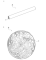
- FIG. 13A is a schematic perspective view of a fiber-reinforced resin pultrusion molded body used in one embodiment of the present invention
- FIG. 13B is a schematic cross-sectional view of the same.
- the pultrusion molded body 30 is a rod-shaped molded body, and the fiber sheet is folded into an amorphous shape in cross section. Further, a thermoplastic resin is filled in and between the fiber sheets and integrated.
- the matrix resin component 31 of the pultrusion molded body 30 is a thermoplastic resin, and is impregnated into the fiber sheet and also filled between the fiber sheets.
- pultrusion marks on the surface of the pultrusion molded body. Further, in the pultrusion molded article, at least some of the fibers constituting the raw material fiber sheet are present on the surface. When the fiber sheet is passed through a die while being converged and pulled out, pultrusion marks remain on the surface of the resulting molded product, allowing it to be determined whether it has been pultruded or not.
- the blending ratio of the resin and reinforcing fibers is preferably 20 to 70 volume % of the reinforcing fibers, when the total is 100 volume %, and the thermoplastic resin is preferably 20 to 70 volume %.
- the volume proportion of the reinforcing fibers is preferably 30 to 80 volume %, more preferably the volume proportion of reinforcing fibers (Vf) is 25 to 60 volume %, and the volume proportion of the thermoplastic resin is 40 to 75 volume %.
- the pultrusion molded body 30 is a continuous product or a product cut into a predetermined length.
- the cross-sectional diameter or thickness of the pultruded body is preferably 0.2 to 15 mm, more preferably 1 to 10 mm.
- the cross-sectional shape can be any shape such as round, square, C-shaped, H-shaped, L-shaped, etc., and the shape can be linear, rod-shaped, plate-shaped, etc.
- the fiber sheet is preferably a semi-preg sheet in which a thermoplastic powder resin, which will become the matrix resin of the pultrusion molded product, is adhered and heat-sealed to the surface of the unidirectional continuous fibers.
- This semi-preg sheet is molded so that the thermoplastic resin on the surface is filled within the fiber sheets and between the fiber sheets.
- the fiber sheet more preferably contains crosslinked fibers intersecting with the unidirectional continuous fibers as a subcomponent, and the thermoplastic resin preferably integrates the unidirectional continuous fibers and the crosslinked fibers.
- the main component of the fibers constituting the fiber sheet is unidirectional continuous fibers that are opened and arranged in parallel in one direction.
- the thermoplastic resin used to form the fiber sheet is preferably a powder, and the thermoplastic powder resin is applied onto the unidirectional continuous fibers and crosslinked fibers, and the thermoplastic resin is thermally melted on or near the surface of the unidirectional continuous fibers. It is preferable that the unidirectional continuous fibers and the crosslinked fibers are integrated. Since this fiber sheet has unidirectional continuous fibers and crosslinked fibers integrated by heat-fused thermoplastic resin, it is easy to handle and has good operability during convergence, drawing, and thermoforming.
- the mass proportion of unidirectional continuous fibers is preferably 75 to 99% by mass, more preferably 80 to 97% by mass, and even more preferably 85% by mass. ⁇ 97% by mass.
- the mass proportion of the crosslinked fibers is preferably 1 to 25% by mass, more preferably 3 to 20% by mass, and even more preferably 3 to 15% by mass. If the mass ratio of each fiber is within the above range, the fiber sheet has high integrity and high tensile strength in the width direction, which is preferable.
- the average length of the crosslinked fibers is preferably 1 mm or more, more preferably 5 mm or more.
- the upper limit of the average length of the crosslinked fibers is preferably 1000 mm or less, more preferably 500 mm or less.
- the fiber sheet has high strength in the width direction and is easy to handle, which is preferable.
- the mass per unit area of the fiber sheet is preferably 10 to 500 g/m 2 , more preferably 20 to 400 g/m 2 , and still more preferably 30 to 300 g/m 2 . When it is within the above range, it is easy to handle the fiber sheet for convergence and pultrusion molding.
- the fiber sheet may also include auxiliary yarns arranged in the other direction with respect to the unidirectional continuous fibers. The auxiliary thread keeps the orientation of the fiber sheet constant. Examples of the auxiliary yarn include glass fiber, aramid fiber, polyester fiber, nylon fiber, and vinylon fiber.
- FIG. 10 is a schematic perspective view of a carbon fiber sheet 1, which is an example of the semi-preg sheet
- FIG. 11 is a schematic cross-sectional view of the carbon fiber sheet 1 shown in FIG.
- crosslinked fibers 3 are arranged in various directions on the surface of the opened unidirectional carbon fiber 2.
- the thermoplastic resin 4 is melted and solidified and attached to the surface of the unidirectional carbon fiber 2 and its vicinity, and the resin 4 is not impregnated into the unidirectional carbon fiber sheet or is only partially impregnated. It is.
- FIG. 10 is a schematic perspective view of a carbon fiber sheet 1, which is an example of the semi-preg sheet
- FIG. 11 is a schematic cross-sectional view of the carbon fiber sheet 1 shown in FIG.
- crosslinked fibers 3 are arranged in various directions on the surface of the opened unidirectional carbon fiber 2.
- the thermoplastic resin 4 is melted and solidified and attached to the surface of the unidirectional carbon fiber 2 and its vicinity, and the resin 4 is not impregnated
- crosslinked fibers 3a and 3b are present on the surface of the unidirectional carbon fiber 2. All of the crosslinked fibers 3a are on the surface of the unidirectional carbon fibers 2. A part of the crosslinked fibers 3b is on the surface of the unidirectional carbon fiber 2, and a part is inside and intersects with the carbon fiber.
- "cross” includes entanglement. For example, some or all of the crosslinked fibers 3 are present within the unidirectional continuous fibers and intersect with the unidirectional continuous fibers in a three-dimensional manner.
- the resin 4 adhesively fixes the crosslinked fibers 3 to the surface of the unidirectional carbon fibers 2. Further, the carbon fiber sheet 1 has a portion to which resin 4 is attached and a portion 5 to which no resin is attached.
- the portion 5 to which the resin is not attached becomes a passage through which the air inside the fiber sheet escapes when the carbon fiber sheet 1 is heated and pultruded, making it easier for the resin on the surface to impregnate the entire inside of the fiber sheet. .
- the resin 4 becomes the matrix resin of the pultrusion molded body.
- FIG. 12 is a schematic process diagram showing the method for manufacturing the semi-preg sheet.
- a group of carbon fiber filaments (tows) 8 are pulled out from a large number of supply bobbins 7 and spread by passing between the spreading rolls 21a to 21j (roll spreading step 23).
- Air opening may be used instead of roll opening.
- the opening roll may be fixed or rotating, or may vibrate in the width direction.
- the opened tow is nipped between nip rolls 9a and 9b, and passed between a plurality of bridge rolls 12a-12b installed between the nip rolls 9a and 9b, and the tension of the tow is adjusted to, for example, per 15,000 rolls (1
- the bridge roll may rotate or vibrate in the width direction.
- the bridge roll is, for example, a plurality of rolls with matte, uneven, or mirror surfaces, and generates crosslinked fibers by bending, fixing, rotating, vibrating, or a combination of carbon fiber filaments.
- 13a-13g are guide rolls.
- crosslinked fibers are generated from the carbon fiber filament group by applying a predetermined tension to the opened carbon fiber filament group, so crosslinked fibers are also generated inside the fiber sheet in the direction across the fiber sheet. This is preferable because it exists and intersects with the unidirectional continuous fibers in a three-dimensional manner.
- dry powder resin 15 is sprinkled on the surface of the spread sheet from the powder supply hopper 14, and is supplied into the heating device 16 in a pressure-free state and heated to melt the dry powder resin 15, and then Cooling.
- dry powder resin 18 is also sprinkled from the powder supply hopper 17 on the back side of the spread sheet, and the dry powder resin 18 is fed into the heating device 19 in a pressure-free state and heated to melt the dry powder resin 18, cooled, and then placed on the winding roll 20. (powder resin application step 25).
- the dry powder resins 15 and 18 are, for example, polyphenylene sulfide resin (melting point: 290°C), and the temperatures in the heating devices 16 and 19 are, for example, +5 to 60°C above the melting point or resin flow temperature of the resin, and the residence time is, for example, Each time is 4 seconds.
- the strength of the carbon fiber sheet in the width direction is increased, and the constituent carbon fibers do not fall apart, allowing it to be handled as a sheet.
- a powder coating method for applying the powder resin, a powder coating method, an electrostatic coating method, a spraying method, a fluidized dipping method, etc. can be adopted.
- a powder coating method in which powdered resin is dropped onto the surface of the spread sheet is preferred.
- powdered resin in the form of dry powder is sprinkled on the spread sheet.
- crosslinked fibers are generated from the carbon fiber filament group by applying a predetermined tension to the spread carbon fiber filament group, but instead of this, the crosslinked fibers are dropped onto the spread sheet. Good too.
- the crosslinked fibers may be present only on one side of the spread sheet, or may be present on both surfaces. If the fiber sheet (semi-preg sheet) does not contain crosslinked fibers, the crosslinked fiber generation step 24 in FIG. 12 may be omitted.
- the pultrusion mold 37 is a pultrusion mold that includes a heating section 34, a forming section 35, and a cooling section 36 in this order along the traveling direction of the fiber sheet.
- the fiber sheet 32 passes through a guide 33, converges, and is supplied to a heating section 34 of a pultrusion mold 37.
- the heating section 34 the fiber sheet 32 is heated to a temperature higher than the melting point or resin flow temperature of the thermoplastic resin present on at least the surface of the fiber sheet 32.
- the resin flow temperature is the temperature at which resin flow begins.
- the fiber sheet is compressed while being pulled out in the traveling direction, and is formed into the shape of the inner cavity of the heating section 34.
- it is drawn into the molding part 35, shaped into the shape of the inner cavity of the molding part 35, and stabilized in that shape within the molding part 35.
- the mold temperature of the molding section 35 is preferably equal to the mold temperature of the heating section 34 .
- it is cooled in the cooling unit 36 to fix the shape.
- the mold temperature of the molding section 35 is, for example, higher than the melting point or resin flow temperature of the thermoplastic resin. It is efficient to use water cooling as the cooling means for the cooling unit 36.
- the obtained pultrusion molded product is pulled out from the pultrusion mold 37 by pultrusion rollers 38a and 38b, and if the molded product is thin, it is rolled up or, if necessary, a fiber-reinforced resin pultrusion molded product 40 of a predetermined length is used with a blade 39. Cut to.
- a matrix resin of the pultrusion molded body is added to the surface of the unidirectional continuous fibers and in the vicinity thereof.
- a fiber sheet (semi-preg sheet) to which a thermoplastic powder resin is fused is used, and the following steps are included.
- one or more fiber sheets are used.
- the fiber sheet is preferably supplied to the heating section in at least one converged state selected from a folded state, a rolled state, and a state in which strip-shaped sheets are stacked.
- the planar fiber sheet can be brought close to a three-dimensional molded body such as a rod shape, and in the obtained pultrusion molded body, the fiber sheet is folded into an amorphous shape.
- convergence refers to gathering or bundling the fiber sheets into a moldable state. For example, the above-mentioned folding, winding, stacking of strip-shaped sheets, etc. are included.
- FIG. 15A shows a fiber sheet 41 in a folded state
- FIG. 15B shows a fiber sheet 42 in a rolled state
- FIG. 15C shows a fiber sheet 43 in a state in which strip-shaped fiber sheets are laminated.
- the fiber sheet 42 may be wound diagonally.
- a guide 33 FIG. 14 or the like can be used as a means for converging the fiber sheet 32.
- the orientation direction of the fibers can be set at an arbitrary angle.
- the rolled sheet When using a rolled fiber sheet, the rolled sheet may be further wound. Winding is possible at any angle.
- the fiber sheets may be laminated, and can be laminated at any angle such as 0°, 45°, or 90°. Usually, it is based on a fiber sheet with a length direction (one direction) of 0°. 0° means that the length direction of the unidirectional continuous fibers of the fiber sheet and the drawing direction of pultrusion molding (length direction of the molded object) are the same direction.
- the amount of insertion of the semi-preg sheet into the pultrusion mold can be changed depending on the target diameter of the pultrusion molded body and the mass per unit length.
- the heating temperature of the fiber sheet (the mold temperature of the heating section 34) is, for example, a temperature equal to or higher than the resin melting temperature, and the drawing speed is preferably 10 mm to 100 m/min. Melting of thermoplastic resin, impregnation between fibers, and molding can be controlled by two conditions: temperature and drawing speed.
- the shape of the internal space of the heating section 34 is preferably a tapered shape, a trumpet shape, etc. in which the diameter decreases in the direction of travel of the fiber sheet.
- the inlet diameter (D1) of the heating section 34 is larger than the target diameter of the pultruded body, and the outlet diameter (D2) of the heating section and the diameter (D3) of the forming section are the same as the target diameter.
- the exit diameter (D2) of the heating section 34 and the diameter (D3) of the molding section 35 are, for example, 1 to 15 mm.
- the ratio of the inlet diameter (D1) of the heating part 34 to the outlet diameter (D2) of the heating part 34 is preferably 1.5 times or more, more preferably 2 times or more, and still more preferably 2.5 times or more. Although there is no upper limit for D1/D2, practically it is preferably 10 times or less, more preferably 8 times or less.
- the fiber sheet 32 that is the material of the pultrusion molded body is compressed in the heating section 34 by a pulling force, in other words, it is compressed while being pulled out in the advancing direction.
- the diameter (D4) of the mold of the cooling section 36 is preferably the same as the exit diameter (D2) of the mold of the heating section 34 and the diameter (D3) of the molding section 35.
- the steps from the supplying step to the drawing step are continuous. If it is a continuous process, manufacturing efficiency is high and manufacturing costs can be reduced.
- the elongated pultrusion molded product obtained after the cooling step can be continuously rolled up or cut into a predetermined length as long as it is thin enough to be rolled up.
- the method for manufacturing a pultrusion molded article according to one embodiment described above is characterized in that a semi-preg sheet is directly molded.
- the fiber sheet (semi-preg sheet) used is flexible and has excellent shapeability, and can be inserted into the heating section 34 as it is, eliminating the need for preheating.
- prepreg since prepreg is hard, it cannot be folded as it is.
- thermoplastic resin in which fiber bundles are bound with a binding material and dipped in a thermoplastic resin solution to make a wire rod, there are restrictions on the selection of thermoplastic resin.
- thermoplastic resin powder is dropped onto the fiber surface of unidirectional continuous fibers (spread sheet) and welded and solidified, so that the pultrusion molded article It can be said that heating and melting of the resin during molding and subsequent cooling can be performed efficiently, and that the moldability of the pultrusion molded product is good and the molding speed is high.
- the fiber reinforced resin sheet is the material of the molded body.
- the fiber-reinforced resin sheet is preferably a non-resin-impregnated and/or semi-resin-impregnated semi-preg sheet containing fibers and a thermoplastic resin and having high flexibility.
- the fiber-reinforced resin sheet is more preferably made of unidirectional continuous fibers (spread sheet) in which continuous fiber groups are opened and arranged in parallel in one direction.
- thermoplastic powder resin becomes a matrix (base material) resin of the molded body during molding of the rib-reinforced molded body, and joins the molded body and the reinforcing ribs to integrate them.
- the fiber reinforced resin sheet may further contain crosslinked fibers intersecting with the unidirectional continuous fibers as a subcomponent, in which case the thermoplastic resin integrates the unidirectional continuous fibers and the crosslinked fibers. It is preferable that the The semi-preg sheet that becomes the main body of the molded body by molding the rib-reinforced molded body is as shown in FIG.
- the fiber-reinforced resin sheet does not contain crosslinked fibers, the crosslinked fiber generation step 24 in FIG. 12 may be omitted. Further, the fiber-reinforced resin sheet can be manufactured by the method for manufacturing a resin-integrated fiber sheet disclosed in WO2021/095626.
- the thermoplastic resin contained in the fiber-reinforced resin sheet is preferably a thermoplastic resin having a softening point lower than that of the thermoplastic resin constituting the pultrusion molded body.
- the volume ratio (Vf) of fibers is preferably 20 to 65 volume %, the ratio of thermoplastic resin is 35 to 80 volume %, and more preferably the volume ratio (Vf) of fibers is 25 to 60 volume %. %, the proportion of thermoplastic resin is 40 to 75% by volume.
- the resin component of the fiber-reinforced resin sheet can be used as the matrix resin component of the molded body, and the reinforcing ribs and the molded body can be integrated, and when manufacturing the rib-reinforced molded body, new resin It is not necessary to add .
- the mass proportion of the unidirectional continuous fibers is preferably 75 to 99% by mass, more preferably It is 80 to 97% by weight, more preferably 85 to 95% by weight. Further, the mass proportion of the crosslinked fibers is preferably 1 to 25% by mass, more preferably 3 to 20% by mass, and still more preferably 5 to 15% by mass. If the mass ratio of each fiber is within the above range, the fiber-reinforced resin sheet has high integrity and high tensile strength in the width direction, which is preferable.
- the average length of the crosslinked fibers is preferably 1 mm or more, more preferably 5 mm or more.
- the upper limit of the average length of the crosslinked fibers is preferably 1000 mm or less, more preferably 500 mm or less. If the average length of the crosslinked fibers is within the above range, the fiber-reinforced resin sheet has high strength in the width direction and is excellent in handleability, which is preferable.
- the mass per unit area of the fiber-reinforced resin sheet is preferably 10 to 3000 g/m 2 , more preferably 20 to 2000 g/m 2 , and still more preferably 30 to 1000 g/m 2 .
- the thickness of one fiber reinforced resin sheet is preferably 0.01 to 5.0 mm.
- a fiber-reinforced resin sheet with a thickness within this range is easy to vacuum-pressure form.
- the preferred number of fiber-reinforced resin sheets to be laminated is 2 to 70, more preferably 2 to 50.
- FIG. 1A to 1C are schematic cross-sectional views of a rib-reinforced molded body according to one embodiment of the present invention.
- FIG. 1A shows a rib-reinforced molded body 51a in which reinforcing ribs 53 are arranged on one main surface (lower surface) of a molded body 52 containing resin or resin and reinforcing fibers (short fibers).
- FIG. 1B shows a rib-reinforced molded body 51b in which a part of the reinforcing ribs 53 is embedded inside the molded body 52, and the remainder of the reinforcing ribs 53 protrudes from one main surface (lower surface) of the molded body 52.
- FIG. 1C shows a rib-reinforced molded body 51c in which a part of the reinforcing ribs 53 is embedded inside the molded body 52, and the remainder of the reinforcing ribs 53 protrudes from the other main surface (upper surface) of the molded body 52. .
- the reinforcing ribs 53 are integrated into the molded body 52.
- two or more of the embodiments shown in FIGS. 1A to 1C can be used in combination.
- the entire reinforcing rib may be embedded inside the molded body 52.
- FIG. 2 is a schematic back view of a rib-reinforced molded body 51d according to another embodiment of the present invention.
- the rib-reinforced molded body 51d includes reinforcing ribs 53a to 53c integrally molded to the molded body 52, and the reinforcing ribs 53a to 53c are arranged parallel to each other on the back surface of the molded body 52.
- FIG. 3 is a schematic back view of a rib-reinforced molded body 51e according to still another embodiment of the present invention.
- the rib-reinforced molded body 51e includes reinforcing ribs 53a and 53b integrally molded on the molded body 52, and the reinforcing ribs 53a and 53b intersect on the back surface of the molded body 52.
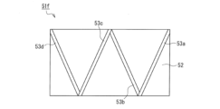
- FIG. 4 is a schematic back view of a rib-reinforced molded body 51f according to still another embodiment of the present invention.
- the rib-reinforced molded body 51f includes reinforcing ribs 53a to 53d integrally molded to the molded body 52, and the reinforcing ribs 53a to 53d are arranged in a W-shape on the back surface of the molded body 52.
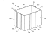
- FIG. 5 is a schematic back view of a rib-reinforced molded body 51g (casing) of still another embodiment of the present invention.
- the rib-reinforced molded body 51g is a casing, and includes a box-shaped molded body consisting of a bottom portion 52e and side portions 52a to 52d.
- the rib-reinforced molded body 51g includes reinforcing ribs 53a-53j integrally molded on the molded body. Two reinforcing ribs are arranged parallel to each other on the outer surfaces of the bottom portion 52e and the side portions 52a-52d, respectively.
- FIG. 6 is a schematic cross-sectional view of a vacuum-pressure forming apparatus used in the method for manufacturing a rib-reinforced molded product according to one embodiment of the present invention, and FIGS. It is a typical process diagram explaining each process of a manufacturing method.
- the vacuum-pressure forming apparatus 60 includes a lower mold 63 having a vacuum line 64 and an upper mold 69 having a pressure line 70.
- the lower mold 63 is fixed on a base 61 and a mold stand 62, and a vacuum line 64 extends to a molding surface 65.
- a vacuum pump (not shown) is connected to the vacuum line 64.
- the upper mold 69 includes an upper mold main body 66 including a pressurizing line 70, and can supply compressed air downward (toward the lower mold 63) from the air groove 67 and the air hole 71 of the face plate 68.
- a compressor (not shown) is connected to the pressurizing line 70.
- the lower mold 63 is heated and cooled by an electromagnetic induction heating type, resistance wire heating type, infrared heating type, or wire heating type heater 72 and a water cooling pipe 73, and can be controlled to a predetermined temperature.
- FIG. 7 shows the preparation process
- FIG. 8A shows the heating and temperature raising process
- FIG. 8B shows the heating vacuum pressure forming process
- FIG. 8C shows the cooling and demolding process.
- a laminate 90 in which a plurality of semi-preg sheets 10 are laminated on the molding surface 65 of the lower mold 63 and reinforcing ribs 30 are arranged on top of the semi-preg sheets 10 is placed on the molding surface 65 of the lower mold 63. I'll put it on.
- the laminate 90 is placed so that the semi-preg sheet 10 faces the molding surface 65.
- the lower mold 63 is covered with a bagging film 74 to form a closed space that can be under a vacuum atmosphere below the bagging film 74.
- an upper mold 69 is placed on the bagging film 74.
- the air inside the lower mold 63 (inside the closed space) is sucked through the vacuum line 64 to reduce the pressure in the closed space, and the laminate 90 is sucked toward the lower mold 63. It is brought into close contact with the mold 63.
- the lower mold 63 is heated by a heater 72 .
- the temperature increase of the lower mold 63 may be started at the same time as the start of pressure reduction, but may be raised either before or after the start of pressure reduction.
- the laminate 90 is heated to a temperature equal to or higher than the softening point of the thermoplastic resin constituting the semi-preg sheet 10 to soften the thermoplastic resin.
- the obtained molded body is cooled while maintaining the pressure conditions in FIG. 8B, and after cooling, the pressure applied to the closed space is released, and the rib reinforced molded body 50 (vacuum pressure molded body).
- the degree of reduced pressure (degree of vacuum) in the closed space due to exhaust from the vacuum line 64 of the lower mold 63 is preferably 0 to 0.1 MPa, and the air pressure of compressed air supplied from the pressurizing line 70 of the upper mold 69 is 0.1 MPa. 1 to 2.0 MPa is preferable.
- a fluororesin film such as polytetrafluoroethylene, a thermal film such as a polyimide resin film, or a silicone rubber sheet can be used.
- the advantages of the method for producing a rib-reinforced molded body according to this embodiment are as follows. (1) Since a semi-preg sheet containing unidirectional continuous fibers (spread sheet) and thermoplastic resin is used as the material for the molded body 10, the molded body 10 is thin, has high strength, and has good shapeability. An excellent rib-reinforced molded product can be obtained.
- direct molding is possible. That is, the laminate 90 can be shaped without preheating (preheating for softening the molding material before placing it in the molding die), and the shaping and resin spread sheet can be performed. The entire filling (impregnation) can be done almost simultaneously. (2) Since direct molding is possible, the thermal history of the resin can be reduced and deterioration of the resin can be prevented. (3) Since the vacuum-pressure forming method uses a bagging film, it is possible to form not only flat shapes but also various three-dimensional shapes.
- FIG. 9A shows an in-mold (injection) molding device 80 used in the method for manufacturing a rib-reinforced molded body of this embodiment.
- the molding device 80 includes an upper mold 81 and a lower mold 82.
- the upper mold 81 and the lower mold 82 are placed apart, but the gap created when these are aligned and overlapped is a cavity.
- Grooves 83a-83c for positioning reinforcing ribs are formed on the surface of the lower mold 82 constituting the cavity.
- 84 is an injection port for molten resin.
- Reinforcing ribs 85a-85c are arranged in the grooves 83a-83c as shown in FIG. 9B.
- the upper mold and the lower mold are aligned and overlapped, and then molten resin 86 is injected from the injection port 84.
- the molten resin is molded into a molded body 87 in a cavity formed between the upper mold 81 and the lower mold 82, and is integrated with the reinforcing ribs 85a-85c.
- the molded body is a laminated base material in which base material layers containing a plurality of resins are laminated, and the reinforcing ribs are arranged inside the laminated base material.
- This is a rib member made of aluminum.
- the rib-reinforced molded body has a structure in which a protrusion corresponding to the outer shape of the rib member disposed inside the laminated base material is formed on one main surface thereof.
- the rib-reinforced molded article of the present invention includes a laminated base material in which a plurality of base material layers are laminated, reinforcing fibers and a thermoplastic resin, and ribs arranged inside the laminated base material.
- the reinforcing fibers include continuous fibers arranged along the length direction of the reinforcing ribs, and a protruding strip corresponding to the outer shape of the rib member is formed on one main surface. Since the rib member contains reinforcing fibers, the strength and rigidity of the ridges are high, and therefore the strength and rigidity of the rib-reinforced molded body are also high. Furthermore, since the protrusions have high strength and rigidity, even if the laminated base material is made thinner, it is possible to provide a rib-reinforced molded body with high strength and rigidity.
- the rib member is preferably a fiber-reinforced resin pultrusion molded article containing reinforcing fibers and a thermoplastic resin.
- the pultrusion molded body the same one as described in [Embodiment 1] can be used.
- the fiber sheet used to form the pultrusion molded body, the reinforcing fibers and thermoplastic resin constituting the fiber sheet, the shape of the pultrusion molded body, the method for manufacturing the pultrusion molded body, etc. are as described in [Embodiment 1] ] It is the same as that explained in .
- the thermoplastic resin constituting the fiber sheet is preferably a thermoplastic resin having a higher softening point than the resin constituting the base layer.
- the base sheet which is the material of the base layer constituting the laminated base material, is not particularly limited, and examples include resin sheets, fiber-reinforced resin sheets containing reinforcing fibers, metal sheets, cellulose sheets, etc. , preferably at least one resin-containing sheet selected from resin sheets and fiber-reinforced resin sheets containing reinforcing fibers.
- the resin-containing sheet is not particularly limited as long as it can be integrally molded with the rib member, but from the viewpoint of molding a high-strength rib-reinforced molded body, a fiber-reinforced resin sheet is more preferable.
- the resin contained in the base layer and the resin-containing sheet may be either a thermosetting resin or a thermoplastic resin, but a thermoplastic resin is preferable.
- thermoplastic resins include polyamide resins, polycarbonate resins, polypropylene resins, polyester resins, polyethylene resins, acrylic resins, phenoxy resins, polystyrene resins, polyimide resins, and polyether ether ketone resins. Usable include, but are not limited to:
- the resin-reinforced resin sheet is made of the fiber-reinforced resin that is the material of the molded body described in [Embodiment 1]. The same thing as the sheet can be used.
- the rib-reinforced molded product of this embodiment is preferably a hot press molded product, a vacuum molded product, a pressure molded product, or a vacuum pressure molded product, and is processed by a hot press molding method, a vacuum forming method, a pressure forming method, and a vacuum pressure molding method.
- the rib-reinforced molded body of this embodiment can be manufactured by integrally molding the rib member and a plurality of base sheets using any one of these molding methods.
- the above-mentioned molding method is preferably any one of vacuum forming, pressure forming, and vacuum pressure forming, and particularly, vacuum forming is preferable. According to the vacuum-pressure forming method, various shapes can be performed while integrating constituent materials, and it is suitable as a method for forming thin-walled molded objects.
- a laminate in which a plurality of resin-containing sheets are laminated and a rib member is arranged between any one of the plurality of resin-containing sheets is heated.
- the laminate is softened and vacuum-formed in a lower mold having a vacuum line, and the laminate is pressure-formed with compressed air supplied from the upper mold to the lower mold.
- a rib-reinforced molded body is formed by a method including the following steps (a) to (d) using a vacuum-pressure forming apparatus including the lower mold, the bagging film, and the upper mold. Manufacture.
- Step of pressing the laminate against the lower mold side a step of vacuum-pressure forming the laminate
- the temperature above the softening point is the temperature at which the resin softens or melts. be.
- the resin-containing sheet is preferably a fiber-reinforced resin sheet, and the thickness of one fiber-reinforced resin sheet is preferably 0.01 to 5.0 mm.
- a fiber-reinforced resin sheet with a thickness within this range is easy to vacuum-pressure form.
- the preferred number of fiber-reinforced resin sheets to be laminated is 5 to 70, more preferably 8 to 50.
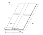
- FIG. 16 is a schematic perspective view of a rib-reinforced molded body 500 according to one embodiment of the present invention
- FIG. 17 is a schematic partial enlarged sectional view of the rib-reinforced molded body 500 shown in FIG. 16.
- the rib-reinforced molded body 500 is a plate-shaped body in which a protruding strip 530 is formed on one main surface 510.
- a rib member 300 is arranged as a reinforcing rib inside a laminated base material 540 including a plurality of base material layers 520, for example, on one main surface 510 side.
- the rib member 300 is disposed between the second and third base material layers 520, and the rib member 300 and the plurality of base material layers 520 are laminated and integrated.
- the base material layer 520 disposed closer to one main surface 510 than the rib member 300 covers the rib member 300 along the outer peripheral surface of the rib member 300.
- a protruding strip 530 corresponding to the outer shape of the rib member 300 is formed as a rib on one main surface 51. Since the rib member 300 is disposed between the base material layers 520, it is not exposed on the surface of the rib-reinforced molded body 500, but is embedded within the rib-reinforced molded body 500.
- the base material layer 520 and the rib member 300 contain thermoplastic resin, in the manufacturing process of the rib-reinforced molded body 500, the resin-containing sheets 100 (see FIG. 18B) that become the base material layer 520 through molding are laminated and integrated. It is possible to integrally mold the rib member 300 and the resin-containing sheet 100. Since the protruding strip 530 is a protruding strip formed corresponding to the outer shape of the rib member 300 containing reinforcing fibers, the protruding strip 530 itself has high strength and rigidity. Therefore, the rib-reinforced molded body 500 has improved strength and rigidity by including the rib member 300 therein.
- the number of base material layers 520 there is no particular restriction on the number of base material layers 520, but the preferred number of layers is 5 to 70, more preferably 8 to 50. There is no particular restriction on the arrangement position of the rib member 300 in the laminated base material layer 520.
- the rib member 300 is a pultrusion molded body, the pultrusion marks and fibers on the surface of the pultrusion molded body, and the fibers constituting the fiber reinforced resin sheet forming the base material layer 520 are hidden with resin, and the rib reinforced molded body 500 is From the viewpoint of improving the smoothness of one surface, it is preferable that the rib member 300 is disposed two or more layers below the one main surface side on which the protruding stripes 530 are formed.
- the direction of the unidirectional continuous fibers may be changed. It may also be laminated.
- the direction of the unidirectional continuous fibers can be changed such as 0°/45°/90°/135°/180°/..., 0°/90°/180°/..., etc. As a result, a molded article having the required mechanical properties can be obtained.
- the rib-reinforced molded body 500 includes one rib member 300, there is no particular restriction on the number of rib members 300, and depending on the size, shape, application, required strength, etc. of the rib-reinforced molded body 500, You can decide as appropriate.
- the rib-reinforced molded body 500 may include a plurality of rib members, the plurality of rib members may be arranged parallel to each other, or the other rib members may be inclined relative to one rib member, and the rib-reinforced molded body 500 may May include braces.
- a method for manufacturing the rib-reinforced molded body 500 shown in FIGS. 16 and 17 will be described as an example. Since the method for manufacturing a rib-reinforced molded body according to this aspect also uses the vacuum-pressure forming apparatus 60 described in [Embodiment 1], a description of the vacuum-pressure forming apparatus 60 will be omitted.
- the manufacturing method of the rib-reinforced molded body 500 of this embodiment is similar to that shown in FIGS. 7 and 8 in [Embodiment 1] except that the laminate 900 shown in FIG. 18B is used instead of the laminate 90 shown in FIG. 7B. This method is the same as the manufacturing method of the rib-reinforced molded body explained using.
- a plurality of resin-containing sheets 100 are stacked on the molding surface 65 of the lower mold 63, and a rib member 300 is arranged between any one of the plurality of resin-containing sheets 100.
- laminate 900 (see FIG. 18B) is placed thereon. At this time, the laminate 900 is placed on the molding surface 65 so that the rib member 300 is far from the molding surface 65.
- the lower mold 63 is covered with a bagging film 74 to form a closed space that can be under a vacuum atmosphere below the bagging film 74. Further, an upper mold 69 is placed on the bagging film 74.
- the air inside the lower mold 63 (inside the closed space) is sucked through the vacuum line 64 to reduce the pressure in the closed space, and the laminate 900 is sucked toward the lower mold 63, and It is brought into close contact with the mold 63.
- the lower mold 63 is heated by a heater 72 .
- the temperature increase of the lower mold 63 may be started at the same time as the start of pressure reduction, but may be raised either before or after the start of pressure reduction.
- the pre-laminated body 900 is heated to a temperature equal to or higher than the softening point of the thermoplastic resin constituting the resin-containing sheet 100 to soften the thermoplastic resin.
- the preferable degree of reduced pressure (degree of vacuum) of the closed space due to exhaust from the vacuum line 64 of the lower mold 63 and the preferable air pressure of the compressed air supplied from the compressed air pipe 70 of the upper mold 69 are respectively [Embodiment 1] It is the same as that in .
- the bagging film 74 used can also be the same as that in [Embodiment 1].
- the advantages of the method for manufacturing a rib-reinforced molded body according to one embodiment of the present invention are as follows. (1) Since the rib member, which has high strength and rigidity due to the inclusion of reinforcing fibers, is embedded in the molded body, it is possible to provide a rib-reinforced molded body that has high strength and rigidity even if the laminated base material is thinned. (2) In particular, if a fiber-reinforced resin sheet (semi-preg) containing continuous fibers is used as the resin-containing sheet 100, a rib-reinforced molded body that is thin but has high strength and excellent shapeability can be obtained. In addition, direct molding is possible.
- the laminate 900 can be shaped without preheating (preheating for softening before placement in a molding die), and the shaping and the entire fiber-reinforced resin sheet of the resin can be performed. Filling (impregnation) can be done almost simultaneously.
- the thermal history of the resin can be reduced and deterioration of the resin can be prevented.
- Three-dimensional shapes can also be formed.
- Example 1 Vacuum pressure forming method
- Unopened carbon fiber tow The unopened carbon fiber tow was manufactured by Mitsubishi Chemical Corporation, product number: PYROFILE TR 50S15L, shape: regular tow, filament 15K (15,000 filaments), and single fiber diameter 7 ⁇ m.
- An epoxy compound is attached as a sizing agent to the carbon fibers of this unopened carbon fiber tow.
- Spreading means for unopened tow The fibers were opened using the opening means shown in FIG. 12. In the crosslinked fiber generation step, the tension of the carbon fiber filament group (tow) was 15 N per 15,000 filaments.
- the unspread tow was made into a spread sheet having 15K carbon fiber filaments, a spread width of 500 mm, and a thickness of 0.08 mm.
- the crosslinked fiber content was 3.3% by mass.
- the average particle size of the dry powder resin was 350 ⁇ m.
- This resin powder was applied in an average of 29.7 g on one side and 59.4 g on both sides to 1 m 2 of carbon fiber (the above-mentioned spread sheet).
- the temperatures in the heating devices 16 and 19 were each 380° C., and the residence time was 4 seconds each.
- the mass of the obtained semi-preg sheet (fiber sheet) was 139.6 g/m 2
- the volume ratio of fiber (Vf) was 50 volume %
- the volume ratio of PPS resin was 50 volume %.
- a pultrusion molded body was formed using the pultrusion processing apparatus shown in FIG. -
- the insertion width of the semi-preg sheet (fiber sheet) was set to 20 mm, and the sheet was folded arbitrarily and supplied to the heating section 34 of the mold.
- the semi-preg sheet heated, compressed and molded in the heating section 34 was passed through the heated molding section 35 to stabilize its shaping and shape.
- the formed semi-preg sheet was cooled in the cooling section 36 to fix its shape.
- the obtained molded body was wound up by a winding machine having a curvature that allows winding.
- the mold temperature of the heating section 34 and the molding section 35 was 400° C.
- the mold temperature of the cooling section 36 (water cooling) was 15° C.
- the drawing speed was 72 mm/min.
- the obtained pultrusion molded product (CFRTP) had a substantially circular cross section and a lot shape with a diameter of 2.5 mm.
- the crosslinked fiber content was 3.3% by mass.
- PA12 resin powder (polyamide 12, melting point: 176°C, manufactured by Ube Industries, Ltd.) was used as the dry powder resin.
- the average particle size of the dry powder resin was 340 ⁇ m.
- This resin powder was applied in an average of 22.5 g on one side and 45.0 g on both sides to 1 m 2 of carbon fiber (the spread sheet).
- the temperatures in the heating devices 16 and 19 were each 240° C., and the residence time was 4 seconds each.
- the mass of the obtained semi-preg sheet (fiber-reinforced resin sheet) was 125 g/m 2
- the volume ratio of fibers (Vf) was 50 volume %
- the volume ratio of PA12 resin was 50 volume %.
- Example 2 Vacuum-pressure forming
- the rib-reinforced molded body of Example 1 was produced using the vacuum-pressure forming apparatus shown in FIGS. 6 to 8 according to the following procedure.
- - Step 1 A laminate of a semi-preg sheet and the above CFRTP was placed on a nickel alloy lower mold according to the above "(1) Lamination conditions". At that time, the above laminate was placed in the lower mold so that the semi-preg sheet faced the lower mold, and later the CFRTP faced the upper mold.
- a bagging film was placed thereon to form a closed space that could be placed under a vacuum atmosphere between the bagging film and the lower mold.
- a silicone rubber sheet with a thickness of 2 mm was used as the bagging film.
- Step 2 The closed space was depressurized from the vacuum line of the lower mold to a degree of decompression of 0.09 MPa, and at the same time as the start of depressurization, the temperature of the lower mold was started to rise.
- ⁇ Process 3 After the lower mold temperature reaches 205°C (molding temperature), the laminate is pressurized at 0.70 MPa with compressed air from above the bagging film, the pressurized state is maintained for 3 minutes, and then vacuum pressure is applied. Molded. Step 3 was performed while maintaining the pressure conditions of Step 2.
- - Step 4 The lower mold was cooled to 50° C. while maintaining the pressure conditions of Step 3, and then the vacuum line and the pressure line were shut off, and the obtained vacuum-pressure molded product was demolded. One cycle of steps 1 to 4 was 400 seconds. The obtained vacuum-pressure molded body was integrally formed with the molded body and the reinforcing ribs.
- the rib-reinforced molded body of Example 1 is a substantially plate-shaped body including one reinforcing rib, and the length of the molded body body is 300 mm, the width is 300 mm, and the thickness (wall thickness). was 1 mm.
- the height of the reinforcing ribs from the surface of the molded body (the surface from which the reinforcing ribs protruded) was 2.5 mm.
- This vacuum-pressure molded product had no warpage, and the strength and rigidity of the reinforcing ribs were high, so the strength and rigidity of the rib-reinforced molded product were also high.
- Example 2 In-mold molding
- the rib-reinforced molded body of Example 2 was produced using an in-mold (injection) molding apparatus shown in FIGS. 9A to 9C. Specifically, reinforcing ribs are placed in grooves formed on the surface of the lower mold that constitutes the cavity, and then the upper and lower molds are aligned and overlapped, and heated to 220°C to melt them. The prepared polypropylene resin (melting point: 160°C) was injected into the cavity from the injection port. Thereafter, the upper mold and the lower mold were water-cooled to cool the mold to 30° C., and then the rib-reinforced molded product (injection molded product) was taken out.
- injection molding apparatus shown in FIGS. 9A to 9C. Specifically, reinforcing ribs are placed in grooves formed on the surface of the lower mold that constitutes the cavity, and then the upper and lower molds are aligned and overlapped, and heated to 220°C to melt them. The prepared polypropylene resin (melting point:
- the molded body and the reinforcing ribs were integrally molded.
- the length of the molded body was 300 mm
- the width was 300 mm
- the thickness (wall thickness) was 1 mm.
- a part of the reinforcing ribs is embedded in the molded body, and the rest protrudes outward from one main surface (lower surface) of the molded body, and The height of the reinforcing ribs from the surface (the side surface from which the reinforcing ribs protruded) was 2 mm.
- This molded product had no warpage and the reinforcing ribs had high strength and rigidity, so the strength and rigidity of the molded product were also high.
- Example 3 Vacuum pressure forming method, rib member embedding type
- Example 3 Vacuum-pressure forming
- the rib-reinforced molded body of Example 3 was produced using the vacuum-pressure forming apparatus shown in FIGS. 6 to 8 according to the following procedure.
- - Step 1 A laminate of a semi-preg sheet and the above CFRTP was placed on a nickel alloy lower mold according to the above "(1) Lamination conditions". At that time, the laminate was placed in the lower mold so that the first semi-preg sheet from the bottom in FIG. 18B faced the lower mold.
- a bagging film was placed over the lower mold to form a closed space that could be placed under a vacuum atmosphere between the bagging film and the lower mold.
- a silicone rubber sheet with a thickness of 2 mm was used as the bagging film.
- Step 2 The closed space was depressurized from the vacuum line of the lower mold to 0.09 MPa, and the temperature of the lower mold was started to increase at the same time as the start of depressurization.
- ⁇ Process 3 After the lower mold temperature reaches 205°C (molding temperature), the laminate is pressurized at 0.70 MPa with compressed air from above the bagging film, the pressurized state is maintained for 3 minutes, and then vacuum pressure is applied. Molded. Step 3 was performed while maintaining the pressure conditions of Step 2.
- Step 4 The lower mold was cooled to 50° C. while maintaining the pressure conditions of Step 3, and then the vacuum line and the pressure line were shut off, and the obtained vacuum-pressure molded product was demolded. One cycle of steps 1 to 4 was 400 seconds.
- FIG. 20 is a photograph of the rib-reinforced molded body of Example 3 produced as described above, the right figure is a photograph taken from one main surface side, and the left figure is a photograph taken from the other main surface side. This is a photo I took.
- the height h of the rib-reinforced molded body of Example 3 was 2 mm, the width w was 30 mm, the thickness (thickness) t was about 1 mm, and the length L was 300 mm (see FIG. 1).
- This molded body does not warp, and the ridges are formed by embedding a pultrusion molded body containing reinforcing fibers inside.
- the strength and rigidity of the protrusions themselves are high, and therefore the strength and rigidity of the rib-reinforced molded body are also high.
- the rib-reinforced molded product of the present invention has high strength in the reinforcing rib itself, so the rib-reinforced molded product has a high reinforcing effect on the molded product body, and is useful for various uses such as frames, plates, shelves, walls, and housings. It is. Furthermore, it can be widely applied in aviation, space, automobiles, sports, three-dimensional printers, industrial applications, building materials, windmills, bicycles, railways, ships, etc.
- Carbon fiber sheet 2 Unidirectional carbon fibers 3, 3a, 3b Crosslinked fibers 4 Resin 5 Portion to which resin is not attached 6
- Supply bobbin 8 Carbon fiber filament group (carbon fiber unspread tow) 9a, 9b Nip roll 10 Fiber reinforced resin sheet (semi-preg sheet) 12a-12b Bridge rolls 13a-13g Guide rolls 14, 17 Powder supply hoppers 15, 18 Dry powder resin 16, 19 Heating device 20 Winding rolls 21a-21j Spreading roll 23 Roll opening process 24 Crosslinked fiber generation process 25 Powder Resin application step 30, 40 Fiber-reinforced resin pultrusion molded body 31 Thermoplastic resin impregnated integral cross section 32, 41-43 Fiber sheet 33 Guide 34 Heating section 35 Molding section 36 Cooling section 37 Molding mold 38a, 38b Drawing roller 39 Blade 51a-51g Rib reinforced molded body 52 Molded body body 53a-53j Reinforcement rib 60 Vacuum pressure forming device 64 Vacuum line 63 Lower mold 69 Upper mold 70 Pressure line 80 In-mold (injection),
Abstract
本発明のリブ補強成形体は、一態様において、樹脂を含む成形体本体52と、補強リブ53とが一体成形されたリブ補強成形体であって、前記補強リブは、前記成形体本体の一方の主面から突出している。本発明のリブ補強成形体は、別の一態様において、基材層が積層された積層基材と、補強繊維と熱可塑性樹脂とを含み、積層基材の内部に配置された補強リブとしてのリブ部材とを含み、リブ補強成形体の一方の主面には、リブ部材300の外形に対応する凸条が形成されたている。補強リブは、補強繊維と熱可塑性樹脂とを含み、補強繊維は、前記補強リブの長さ方向に沿って配置された連続繊維を含む。補強リブは、好ましくは、樹脂を含む繊維シートが無定形に折り畳まれ、折り畳まれた繊維シート内及び繊維シート間に前記樹脂が充填し一体化された、繊維補強樹脂引抜成形体である。
Description
本発明は、リブ補強成形体及びその製造方法に関する。
強化繊維材料である炭素繊維は、各種のマトリックス樹脂と複合化され、得られる繊維強化プラスチックは種々の分野・用途に広く利用されるようになってきた。高度の機械的特性や耐熱性等を要求される航空・宇宙分野や、一般産業分野では、マトリックス樹脂である熱可塑性樹脂とともに、一方向性の連続繊維が用いられている。
従来から、樹脂と一方向性の連続繊維の複合材料として、例えば、炭素繊維基材に樹脂を完全含浸して得られるプリプレグが用いられている。このような複合材料を用いて成形された成形体の曲げ性能や耐衝撃性能を向上させるために、特許文献1は、強化繊維にマトリックス樹脂を含浸させたプリプレグの一方の面に、格子状となるように熱可塑性樹脂を射出成形して、格子状の補強リブとプリプレグとを接合一体化した成形品を提案している。特許文献2は、厚さ0.01~2.0mmの単層または複層の可撓性を有する炭素繊維複合材料板の表面および/または中間層に厚み0.01~30mmの熱可塑性樹脂層を射出成形して、結合一体化せしめて得た炭素繊維複合成形品を開示している。特許文献3は、強化繊維にマトリックス樹脂を含浸させたプリプレグを金型内で加熱しておき、溝部に熱可塑性樹脂を溶融して射出充填し、射出成形された補強リブと前記プリプレグと一体成形することを提案している。
繊維強化プラスチック、特に繊維強化熱可塑性プラスチック(FRTP)が用いられる製品に対する小型化の要請は依然として高い。当然ながら使用される繊維強化熱可塑性プラスチックについて薄肉化が要求される。繊維強化熱可塑性プラスチックの薄肉化による剛性の低下を補うために、補強リブを設けることが考えられるが、前記従来技術では、補強リブ自体の強度及び剛性に問題があり、強度及び剛性の高い成形体を得ることは困難であった。
本発明は、薄肉化しても強度及び剛性が高いリブ補強成形体及びその製造方法を提供する。
本発明は、一態様において、樹脂を含む成形体本体と補強リブとが一体成形されたリブ補強成形体であって、前記補強リブは、補強繊維と熱可塑性樹脂とを含み、前記補強繊維は、前記補強リブの長さ方向に沿って配置された連続繊維を含む、リブ補強成形体に関する。
本発明は、一態様において、本発明のリブ補強成形体の一例の製造方法であって、
樹脂を含む成形体本体の材料の上に補強リブを配置した積層体を加熱軟化させること、減圧ラインを有する下金型内で前記積層体を真空成形すること、加圧ラインを有する上金型から前記下金型側に圧縮空気を供給して前記積層体を圧空プレスすること、を含む真空圧空成形をし、又は、
成形金型のキャビティ内に前記補強リブを位置決め配置した後、前記キャビティ内に溶融樹脂を含む前記成形体本体の材料を注入して、インジェクション成形をすることにより、前記成形体本体と前記補強リブとを一体成形させる、リブ補強成形体の製造方法に関する。
樹脂を含む成形体本体の材料の上に補強リブを配置した積層体を加熱軟化させること、減圧ラインを有する下金型内で前記積層体を真空成形すること、加圧ラインを有する上金型から前記下金型側に圧縮空気を供給して前記積層体を圧空プレスすること、を含む真空圧空成形をし、又は、
成形金型のキャビティ内に前記補強リブを位置決め配置した後、前記キャビティ内に溶融樹脂を含む前記成形体本体の材料を注入して、インジェクション成形をすることにより、前記成形体本体と前記補強リブとを一体成形させる、リブ補強成形体の製造方法に関する。
本発明は、一態様において、本発明のリブ補強成形体の別の一例の製造方法であって、
樹脂を含み成形体本体を構成する基材層の材料である基材シートを複数枚積層し、複数枚の前記基材シートのうちのいずれかの基材シート間に補強繊維と熱可塑性樹脂とを含むリブ部材を補強リブとして配置し、前記リブ補強成形体の一方の主面に前記リブ部材の外形に対応する凸条が形成されるように前記リブ部材と積層された複数枚の前記基材シートとを、真空成形法、圧空成形法又は真空圧空成形法により一体成形する、リブ補強成形体の製造方法に関する。
樹脂を含み成形体本体を構成する基材層の材料である基材シートを複数枚積層し、複数枚の前記基材シートのうちのいずれかの基材シート間に補強繊維と熱可塑性樹脂とを含むリブ部材を補強リブとして配置し、前記リブ補強成形体の一方の主面に前記リブ部材の外形に対応する凸条が形成されるように前記リブ部材と積層された複数枚の前記基材シートとを、真空成形法、圧空成形法又は真空圧空成形法により一体成形する、リブ補強成形体の製造方法に関する。
本発明のリブ補強成形体は、樹脂を含む成形体本体に一体成形された補強リブを含み、前記補強リブを構成する補強繊維が、補強リブの長さ方向に沿って配置された連続繊維を含むので、補強リブ自体の強度及び剛性が高く、成形体本体を薄肉化しても強度及び剛性が高いリブ補強成形体を提供できる。
また、本発明のリブ補強成形体の一例の製造方法では、通常の加熱プレス成形法に加えて、真空圧空成形法又はインジェクション成形法により、前記補強リブを前記成形体本体の材料とともに一体成形することができるので、前記リブ補強成形体を効率よく製造できる。
また、本発明のリブ補強成形体の別の一例の製造方法では、樹脂を含む基材シートを複数枚積層し、複数枚の前記基材シートのうちのいずれかのシート間に補強繊維と熱可塑性樹脂とを含むリブ部材を配置し、これらを、真空成形法、圧空成形法又は真空圧空成形法により一体成形するので、強度および剛性が高く、種々の形状の本発明のリブ補強成形体を製造できる。
また、本発明のリブ補強成形体の一例の製造方法では、通常の加熱プレス成形法に加えて、真空圧空成形法又はインジェクション成形法により、前記補強リブを前記成形体本体の材料とともに一体成形することができるので、前記リブ補強成形体を効率よく製造できる。
また、本発明のリブ補強成形体の別の一例の製造方法では、樹脂を含む基材シートを複数枚積層し、複数枚の前記基材シートのうちのいずれかのシート間に補強繊維と熱可塑性樹脂とを含むリブ部材を配置し、これらを、真空成形法、圧空成形法又は真空圧空成形法により一体成形するので、強度および剛性が高く、種々の形状の本発明のリブ補強成形体を製造できる。
[実施形態1]
本発明は、樹脂を含む成形体本体と補強リブとが一体成形されたリブ補強成形体である。前記補強リブは、熱可塑性樹脂を含むことから、樹脂を含む成形体本体の材料と一体化成形が可能である。また、前記補強リブは、補強繊維として、補強リブの長さ方向に沿って配置された連続繊維を含むので、補強リブ自体の強度及び剛性が高い。なお、「前記補強リブの長さ方向に沿って配置された」とは、連続繊維の長さ方向が全体として補強リブの長さ方向に沿っていることを意味し、「前記補強リブの長さ方向に沿って配置された連続繊維」は、連続繊維が、補強リブの長さ方向に沿って直線的に配置される場合に限定されず、螺旋状やジグザグ状に配置される場合も包含する。
本発明は、樹脂を含む成形体本体と補強リブとが一体成形されたリブ補強成形体である。前記補強リブは、熱可塑性樹脂を含むことから、樹脂を含む成形体本体の材料と一体化成形が可能である。また、前記補強リブは、補強繊維として、補強リブの長さ方向に沿って配置された連続繊維を含むので、補強リブ自体の強度及び剛性が高い。なお、「前記補強リブの長さ方向に沿って配置された」とは、連続繊維の長さ方向が全体として補強リブの長さ方向に沿っていることを意味し、「前記補強リブの長さ方向に沿って配置された連続繊維」は、連続繊維が、補強リブの長さ方向に沿って直線的に配置される場合に限定されず、螺旋状やジグザグ状に配置される場合も包含する。
前記補強リブは、成形体本体の材料との一体成形の前に予め成形された繊維補強樹脂引抜成形体(以下、以下「引抜成形体」と略称する場合もある。)が好ましい。引抜成形体は、繊維シートが引抜成形され、当該繊維シートが、例えば、無定形に折り畳まれ、折り畳まれた繊維シート内及び繊維シート間に樹脂が充填されて一体化したものであると好ましい。収束させた繊維シートを、ダイス(引抜成形金型)を通過させると引抜成形体が得られる。得られた引抜成形体は、その内部において繊維シートが無定形に折り畳まれた状態であり、繊維シートを構成する熱可塑性樹脂が溶融して繊維シート内及び繊維シート間に充填されることによりマトリックス樹脂となった、中実成形体である。ここで言う充填とは、熱可塑性樹脂が繊維シート内に含浸し、繊維シートと繊維シートの間に満ちることを言う。このようにして成形された引抜成形体においてはボイドが少ない。また、引抜成形体の内部において繊維シートが無定形に折り畳まれた状態であるので、引抜成形体は、引抜成形体の長さ方向と直交する断面において方向性のない均一な応力の成形体となる。故に、引抜成形体は補強材として好適である。
前記繊維シートは、補強繊維と熱可塑性樹脂とを含み、柔軟性が高い、樹脂未含浸及び/又は樹脂半含浸のセミプレグシートであると、引抜成形性が良いため好ましく、前記繊維シートの繊維表面にマトリックスとなる熱可塑性粉体樹脂を融着させたセミプレグシートがより好ましい。当該セミプレグシートを用いることで、引抜成形性が良く、連続的な引抜成形体の成形が可能である。リブ補強成形体の強度および剛性の向上の観点から、繊維シートは、更に好ましくは、連続繊維群(補強繊維)が開繊され一方向に並列状に配列された一方向連続繊維(開繊シート)の繊維表面に引抜成形体の成形時にマトリックスとなる熱可塑性粉体樹脂を融着させたセミプレグシートである。引抜成形法は、汎用性のある成形方法であり、様々な形状の引抜成形体を成形でき、二次加工性が良く、曲線状の線状物やリベット等の部品への加工も容易である。
前記引抜成形体を構成する補強繊維は、短繊維および連続繊維のうちのいずれか一方または双方であってもよいが、なかでも、炭素繊維、ガラス繊維及び弾性率が380cN/dtex以上の高弾性率繊維から選ばれる少なくとも1種の連続繊維を含んでいると好ましい。前記高弾性率繊維としては、例えばアラミド繊維、とくにパラ系アラミド繊維(弾性率:380~980cN/dtex)、ポリアリレート繊維(弾性率:600~741cN/dtex)、ヘテロ環ポリマー(PBO,弾性率:1060~2200cN/dtex)繊維、高分子量ポリエチレン繊維(弾性率:883~1413cN/dtex)、ポリビニルアルコール繊維(PVA,強度:14~18cN/dtex)などがある。これらの繊維は樹脂強化繊維として有用である。特に軽量化の観点から炭素繊維は有用である。
前記繊維シートを構成する熱可塑性樹脂はとしては、ポリアミド系樹脂、ポリカーボネート系樹脂、ポリプロピレン系樹脂、ポリエステル系樹脂、ポリエチレン系樹脂、アクリル系樹脂、フェノキシ樹脂、ポリスチレン系樹脂、ポリイミド系樹脂、ポリエーテルエーテルケトン系樹脂、及びポリフェニレンサルファイド樹脂などが使用可能であるが、これらに限定されない。リブ補強成形体の成形性の観点から、繊維シートを構成する熱可塑性樹脂は、成形体本体を構成する樹脂よりも軟化点が高い熱可塑性樹脂であると好ましい。
前記補強リブは、角ロッド、丸ロッド、扁平状ロッド及び板状ロッドからなる群から選ばれる少なくとも1種のロッドであるのが好ましい。引抜成形体の製造過程で使用するダイス形状に応じて、引抜成形体の断面を様々な形状とすることができる。
前記成形体本体は、樹脂のみから形成されてもよいが、リブ補強成形体の強度および剛性の向上の観点から、強化繊維を含んでいると好ましい。前記強化繊維は、短繊維および連続繊維のうちのいずれか一方または双方であってもよい。前記成形体本体に含まれる樹脂は、熱硬化性樹脂および熱可塑性樹脂のいずれであってもよいが、熱可塑性樹脂が好ましい。熱可塑性樹脂としては、ポリアミド系樹脂、ポリカーボネート系樹脂、ポリプロピレン系樹脂、ポリエステル系樹脂、ポリエチレン系樹脂、アクリル系樹脂、フェノキシ樹脂、ポリスチレン系樹脂、ポリイミド系樹脂、及びポリエーテルエーテルケトン系樹脂などが使用可能であるが、これらに限定されない。前記成形体本体に前記強化繊維が含まれる場合、樹脂と強化繊維の配合割合は、全体を100体積%としたとき、好ましくは繊維の体積割合(Vf)は20~65体積%、熱可塑性樹脂の体積割合は35~80体積%であり、より好ましくは繊維の体積割合(Vf)は25~60体積%、熱可塑性樹脂の体積割合は40~75体積%である。前記強化繊維は、炭素繊維、ガラス繊維及び弾性率が380cN/dtex以上の高弾性率繊維から選ばれる少なくとも1種の繊維を含んでいると好ましい。前記高弾性率繊維の具体例は、前記補強繊維の一例として説明した高弾性率繊維と同じである。
前記成形体本体は、前記強化繊維を含む繊維強化樹脂シートが1枚または複数枚積層され一体化することにより形成されたものであってもよい。前記成形体本体の材料である前記繊維強化樹脂シートは、プリプレグシートおよびセミプレグシートのいずれであってもよいが、リブ補強成形体の肉薄化と高強度との両立の観点から、連続繊維群が開繊され一方向に並列状に配列された一方向連続繊維(開繊シート)の繊維表面に熱可塑性粉体樹脂を融着させたセミプレグシートが好ましく、軽量化の観点から、連続繊維は炭素繊維が好ましい。
前記リブ補強成形体は、好ましくは、加熱プレス成形体、真空成形体、圧空成形体、真空圧空成形体、又はインジェクション成形体であると好ましい。本発明のリブ補強成形体の一例の製造方法では、例えば、加熱プレス成形法、真空成形法、圧空成形法及び真空圧空成形法のうちの一種以上の成形方法により、補強リブと成形体本体とを一体成形できる。上記成形法は、真空成形法、圧空成形法及び真空圧空成形法のうちのいずれか一種の成形方法が好ましく、なかでも、真空圧空成形法が好ましい。
真空圧空成形法は、例えば、真空ラインを有する下金型と加熱軟化した成形材料との間を真空状態にして、成形材料を下金型側に吸引し下金型へ密着させ(真空成形)、加圧ラインを有する上金型から下金型側に供給される圧縮空気で加熱軟化した成形材料を下金型に押し付ける(圧空プレスする)成形方法である。成形体本体の材料として、例えば、1枚または積層された複数枚の上記セミプレグシートを用いれば、セミプレグシートを構成する樹脂が、セミプレグシート内およびセミプレグシート間に充填されて成形体本体のマトリックス樹脂となり、セミプレグシートが成形体本体となるとともに、成形体本体と補強リブとが一体化される。真空圧空成形法は、成形材料を一体化しながら様々な賦形が行え、薄肉の成形体の成形方法として好適である。
インジェクション成形はインモールド成形ともいわれ、成形速度が高く、熱可塑性樹脂、又は短繊維を含む熱可塑性樹脂を高い成形速度で成形できる。
加熱プレス成形の場合、例えば、補強リブを位置決め配置できる溝を有した下金型に補強リブを載置し、当該補強リブの上に複数枚の上記セミプレグシートを積層し、補強リブと上記セミプレグシートとを、加熱された下金型と加熱された上金型で挟みプレスしてもよい。このような成形方法であれば、補強リブの位置精度が向上する。
インジェクション成形はインモールド成形ともいわれ、成形速度が高く、熱可塑性樹脂、又は短繊維を含む熱可塑性樹脂を高い成形速度で成形できる。
加熱プレス成形の場合、例えば、補強リブを位置決め配置できる溝を有した下金型に補強リブを載置し、当該補強リブの上に複数枚の上記セミプレグシートを積層し、補強リブと上記セミプレグシートとを、加熱された下金型と加熱された上金型で挟みプレスしてもよい。このような成形方法であれば、補強リブの位置精度が向上する。
本発明のリブ補強成形体の製造方法は、好ましくは、積層された複数枚の前記セミプレグシートの上に補強リブが配置された積層体を加熱軟化させ、真空ラインを有する下金型内で前記積層体を真空成形し、加圧ラインを有する上金型から下金型側へ供給する圧縮空気で前記積層体を圧空成形することを含む。具体的には、好ましくは、前記下金型とバッギングフィルムと前記上金型とを含む真空圧空成形装置を用いて、下記工程(a)~(d)を含む方法によりリブ補強成形体を製造する。
(a)下金型内に上記積層体を配置した後、前記下金型にバッギングフィルムを被せて、バッギングフィルムと下金型の間に真空雰囲気下とし得る閉空間を形成する工程
(b)前記閉空間を真空ラインから減圧して、積層体を下金型に密着させ、且つ、前記下金型を昇温させる工程
(c)前記(b)の圧力条件を維持したまま、前記積層体を前記セミプレグシートに含まれる樹脂の軟化点以上の温度に加熱した状態で、バッギングフィルムの上方に配置された上金型から下金型側へ圧縮空気を供給して前記積層体を前記下金型側に押圧する工程(前記積層体を真空圧空成形をする工程)
(d)前記(c)の圧力条件を維持したまま得られた成形体を冷却し、冷却後に成形体を脱型する工程
尚、バッギングフィルムは、バギングフィルム又は真空バッグフィルムともいう。
前記(a)において、前記セミプレグシートが下金型と対向するように、上記積層体を下金型内に配置する。
軟化点以上の温度とは、樹脂が軟化もしくは溶融する温度である。
前記(a)において、前記セミプレグシートが下金型と対向するように、上記積層体を下金型内に配置する。
軟化点以上の温度とは、樹脂が軟化もしくは溶融する温度である。
本発明のリブ補強成形体の製造方法では、前記補強リブとして、好ましくは、繊維シートを引抜成形することにより得られる繊維補強樹脂引抜成形体を用いる。前記繊維シートは、好ましくは、連続繊維群が開繊され一方向に並列状に配列された一方向連続繊維の表面に熱可塑性粉体樹脂を融着させたセミプレグシートである。繊維補強樹脂引抜成形体の製造方法は、一態様において、好ましくは、
前記繊維シートを収束して引抜成形金型の加熱部に供給し、
前記加熱部で前記熱可塑性樹脂の融点または樹脂流動温度以上に加熱しながら、前記繊維シートを圧縮し、
圧縮された前記繊維シートを、前記引抜成形金型の成形部で成形し、次いで、前記引抜成形金型の冷却部で冷却することにより引抜成形体が得られ、前記引抜成形体を前記引抜成形金型から引き抜くことを含む。
前記繊維シートを収束して引抜成形金型の加熱部に供給し、
前記加熱部で前記熱可塑性樹脂の融点または樹脂流動温度以上に加熱しながら、前記繊維シートを圧縮し、
圧縮された前記繊維シートを、前記引抜成形金型の成形部で成形し、次いで、前記引抜成形金型の冷却部で冷却することにより引抜成形体が得られ、前記引抜成形体を前記引抜成形金型から引き抜くことを含む。
[引抜成形体]
以下、本発明のリブ補強成形体の成形に使用する補強リブの好ましい一例である引抜成形体について、図13~図15を用いてより詳細に説明する。
図13Aは本発明の一態様で使用する繊維補強樹脂引抜成形体の模式的斜視図、図13Bは同模式的断面図である。引抜成形体30はロッド状成形体であり、断面において繊維シートは無定形に折り畳まれた状態である。また、繊維シート内及び繊維シート間に熱可塑性樹脂が充填し一体化されている。図13Bにおいて、引抜成形体30のマトリックス樹脂成分31は熱可塑性樹脂であり、繊維シート内に含浸され、繊維シート間にも充填されている。
以下、本発明のリブ補強成形体の成形に使用する補強リブの好ましい一例である引抜成形体について、図13~図15を用いてより詳細に説明する。
図13Aは本発明の一態様で使用する繊維補強樹脂引抜成形体の模式的斜視図、図13Bは同模式的断面図である。引抜成形体30はロッド状成形体であり、断面において繊維シートは無定形に折り畳まれた状態である。また、繊維シート内及び繊維シート間に熱可塑性樹脂が充填し一体化されている。図13Bにおいて、引抜成形体30のマトリックス樹脂成分31は熱可塑性樹脂であり、繊維シート内に含浸され、繊維シート間にも充填されている。
前記引抜成形体の表面には引抜痕がある。また、引抜成形体は、原料の繊維シートを構成する少なくとも一部の繊維が表面に存在する。繊維シートを収束させながらダイスを通過させ、引き抜くと、得られた成形体の表面には引抜痕が残り、引抜成形したかどうかの判別ができる。
引抜成形体30の材料である繊維シートにおける、樹脂と強化繊維の配合割合は、全体を100体積%としたとき、好ましくは補強繊維の体積割合(Vf)は20~70体積%、熱可塑性樹脂の体積割合は30~80体積%であり、より好ましくは補強繊維の体積割合(Vf)は25~60体積%、熱可塑性樹脂の体積割合は40~75体積%である。これにより、繊維シートの樹脂成分を、そのまま引抜成形体30のマトリックス樹脂成分31にすることができ、引抜成形体30を製造する際に、新たな樹脂の追加は不要である。
前記引抜成形体30は、連続物又はこれを所定の長さにカットしたものである。引抜成形体の断面直径又は厚さは0.2~15mmが好ましく、より好ましくは1~10mmである。断面形状は、丸型、角型、C型、H型、L型等、任意の形状にでき、その形態は、線状、ロッド状、プレート状(板状)等にできる。
前記繊維シートとしては、前記一方向連続繊維の表面に、前記引抜成形体のマトリックス樹脂となる熱可塑性粉体樹脂を付着させ熱融着させたセミプレグシートが好ましい。このセミプレグシートは、成形により、表面の熱可塑性樹脂が繊維シート内及び繊維シート間に充填される。これにより、賦形性(成形性)に優れ、ボイドが少ない引抜成形体が得られる。
前記繊維シートは、更に好ましくは、一方向連続繊維と交錯する方向の架橋繊維を副成分として含み、かつ熱可塑性樹脂は、前記一方向連続繊維と前記架橋繊維とを一体化していると好ましい。繊維シートを構成する繊維の主成分は、開繊され一方向に並列状に配列された一方向連続繊維である。繊維シートの形成に使用する熱可塑性樹脂は、好ましくは粉体であり、一方向連続繊維及び架橋繊維の上から熱可塑性粉体樹脂を付着させ、一方向連続繊維の表面又はその付近で熱融着させ、かつ一方向連続繊維と架橋繊維とを一体化していることが好ましい。この繊維シートは、一方向連続繊維と架橋繊維が、熱融着した熱可塑性樹脂により一体化しているため、取り扱い性が良好で、収束、引抜、及び加熱成形する際の操作性が良い。
前記繊維シートにおける一方向連続繊維と架橋繊維の合計を100質量%としたとき、一方向連続繊維の質量割合は75~99質量%が好ましく、より好ましくは80~97質量%、さらに好ましくは85~97質量%である。また、架橋繊維の質量割合は1~25質量%が好ましく、より好ましくは3~20質量%、さらに好ましくは3~15質量%である。各繊維の質量割合が前記の範囲内であれば、繊維シートは、その一体性が高く、幅方向の引張強度が高いので好ましい。架橋繊維の平均長さは、1mm以上が好ましく、さらに好ましくは5mm以上である。架橋繊維の平均長さの上限は1000mm以下が好ましく、より好ましくは500mm以下である。架橋繊維の平均長さが前記の範囲内であれば、繊維シートは、その幅方向の強度が高く、取り扱い性に優れ、好ましい。
前記繊維シートの単位面積あたりの質量は、10~500g/m2が好ましく、より好ましくは20~400g/m2であり、さらに好ましくは30~300g/m2である。前記の範囲内であると、繊維シートを収束し引抜成形するのに取り扱いやすい。
また、繊維シートは、一方向連続繊維に対して他方向に配置されている補助糸を含んでもよい。補助糸は、繊維シートの配向性を一定に保つものである。補助糸としては、例えば、ガラス繊維、アラミド繊維、ポリエステル繊維、ナイロン繊維、ビニロン繊維等が挙げられる。
また、繊維シートは、一方向連続繊維に対して他方向に配置されている補助糸を含んでもよい。補助糸は、繊維シートの配向性を一定に保つものである。補助糸としては、例えば、ガラス繊維、アラミド繊維、ポリエステル繊維、ナイロン繊維、ビニロン繊維等が挙げられる。
次に、図10~図12を用いて、引抜成形体の材料である前記繊維シート(セミプレグシート)の一例について、より詳細に説明する。図10は、前記セミプレグシートの一例である炭素繊維シート1の模式的斜視図、図11は、図10に示した炭素繊維シート1の模式的断面図である。図10において、開繊された一方向炭素繊維2の表面には架橋繊維3が様々な方向に配置している。一方向炭素繊維2の表面およびその付近に熱可塑性樹脂4が溶融固化して付着しており、樹脂4は一方向炭素繊維シートの内部には含浸していないか又は一部含浸している程度である。図11に示すように、一方向炭素繊維2の表面には架橋繊維3a,3bが存在する。架橋繊維3aは全部が一方向炭素繊維2の表面にある。架橋繊維3bは一部が一方向炭素繊維2の表面にあり、一部は内部に入って炭素繊維と交錯した状態である。ここで交錯とは、絡み合いを含む。例えば、架橋繊維3の一部または全部は一方向性連続繊維内に存在し、一方向性連続繊維と立体的に交錯している。樹脂4は架橋繊維3を一方向炭素繊維2の表面に接着固定している。また、炭素繊維シート1には、樹脂4が付着している部分と、樹脂が付着していない部分5がある。樹脂が付着していない部分5は、炭素繊維シート1を加熱し、引抜成形する際に、繊維シート内部の空気がこの部分から抜ける通路となり、表面の樹脂が繊維シート内全体に含浸しやすくなる。これにより樹脂4は引抜成形体のマトリックス樹脂となる。
図12は、上記セミプレグシートの製造方法を示す模式的工程図である。多数個の供給ボビン7から炭素繊維フィラメント群(トウ)8を引き出し、開繊ロール21a-21jの間を通過させることで、開繊させる(ロール開繊工程23)。ロール開繊に代えて、エアー開繊としてもよい。開繊ロールは固定又は回転してもよく、幅方向に振動してもよい。開繊工程の後、開繊されたトウをニップロール9a,9b間でニップし、この間に設置した複数のブリッジロール12a-12bの間を通過させ、トウの張力を例えば15,000本あたり(1個の供給ボビンから供給される炭素繊維フィラメント群に相当)2.5~30Nの範囲でかけることで、架橋繊維を発生させることができる(架橋繊維発生工程24)。ブリッジロールは回転してもよく、幅方向に振動してもよい。ブリッジロールは、例えば表面が梨地、凹凸、または鏡面の複数ロールであり、炭素繊維フィラメント群の屈曲、固定、回転、振動又はこれらの組み合わせにより架橋繊維を発生させる。13a-13gはガイドロールである。上記の通り、開繊された炭素繊維フィラメント群に所定の張力をかけることで、炭素繊維フィラメント群から架橋繊維を発生させているため、繊維シートの内部にも繊維シートを横切る方向に架橋繊維が存在し、一方向性連続繊維と立体的に交錯することとなり、好ましい。
その後、粉体供給ホッパー14からドライパウダー樹脂15を開繊シートの表面に振りかけ、圧力フリー状態で加熱装置16内に供給し加熱し、ドライパウダー樹脂15を溶融し、ガイドロール13e-13g間で冷却する。その後、開繊シートの裏面にも粉体供給ホッパー17からドライパウダー樹脂18を振りかけ、圧力フリー状態で加熱装置19内に供給し加熱し、ドライパウダー樹脂18を溶融し、冷却し、巻き上げロール20に巻き上げられる(粉体樹脂付与工程25)。ドライパウダー樹脂15、18は、例えば、ポリフェニレンサルファイド樹脂(融点:290℃)とし、加熱装置16,19内の各温度は例えば当該樹脂の融点又は樹脂流動温度の+5~60℃、滞留時間は例えば各4秒とする。これにより、炭素繊維シートは幅方向の強度が高くなり、構成炭素繊維がバラバラになることはなく、シートとして扱えるようになる。
粉体樹脂の付与は、粉体塗布法、静電塗装法、吹付法、流動浸漬法などが採用できる。開繊シート表面に粉体樹脂を落下させる粉体塗布法が好ましい。例えばドライパウダー状の粉体樹脂を開繊シートに振りかける。
上記の通り、開繊された炭素繊維フィラメント群に所定の張力をかけることで、炭素繊維フィラメント群から架橋繊維を発生させているが、これに代えて、開繊シートに架橋繊維を落下させてもよい。架橋繊維は、開繊シートの片面上にのみ存在してもよいし、両表面上に存在していてもよい。繊維シート(セミプレグシート)が架橋繊維を含まない場合は、図12において、架橋繊維発生工程24を省略すればよい。
次に、本発明のリブ補強成形体の成形に使用する引抜成形体の製造方法の一例について、図14を用いて説明する。図14において、引抜成形金型37は、繊維シートの進行方向に沿って加熱部34と成形部35と冷却部36とをこの順で備えた引抜成形金型である。繊維シート32は、ガイド33を通過させ、収束して引抜成形金型37の加熱部34に供給する。加熱部34において前記繊維シート32を、前記繊維シート32の少なくとも表面に存在する熱可塑性樹脂の融点または樹脂流動温度以上に加熱する。樹脂流動温度とは、樹脂の流動が開始する温度である。加熱部34では、繊維シートを、前記進行方向へ引き抜きながら圧縮し、加熱部34の内腔の形状に成形する。次いで、成形部35内に引き込み、成形部35の内腔の形状に賦形し、成形部35内にて、その形状に安定化する。成形部35の金型温度は、加熱部34の金型温度と等しいと好ましい。次いで、冷却部36で冷却して形状を固定する。成形部35の金型温度は、例えば、熱可塑性樹脂の融点または樹脂流動温度以上とする。冷却部36の冷却手段は、水冷とするのが効率的である。得られた引抜成形体は引抜ローラー38a,38bにより引抜成形金型37から引き抜かれ、成形体が細い場合は巻き取りあるいは、必要に応じてブレード39で所定長さの繊維補強樹脂引抜成形体40にカットする。
したがって、本発明のリブ補強成形体の成形に使用する引抜成形体の製造方法は、一態様において、引抜成形体の材料として、一方向連続繊維の表面およびその近傍に前記引抜成形体のマトリックス樹脂となる熱可塑性粉体樹脂を融着させた繊維シート(セミプレグシート)を使用し、次の工程を含む。
(1)前記繊維シートを収束して引抜成形金型の加熱部に供給する供給工程
(2)前記引抜成形金型の加熱部で前記熱可塑性樹脂の融点または樹脂流動温度以上に加熱しながら、前記繊維シートを引き抜き力で圧縮する加熱圧縮工程
(3)圧縮された前記繊維シートを前記引抜成形金型の成形部で成形する成形工程
(4)得られた成形体を前記引抜成形金型の冷却部で冷却して引抜成形体とする冷却工程
(5)前記引抜成形体を前記引抜成形金型から引き抜く引抜工程
(1)前記繊維シートを収束して引抜成形金型の加熱部に供給する供給工程
(2)前記引抜成形金型の加熱部で前記熱可塑性樹脂の融点または樹脂流動温度以上に加熱しながら、前記繊維シートを引き抜き力で圧縮する加熱圧縮工程
(3)圧縮された前記繊維シートを前記引抜成形金型の成形部で成形する成形工程
(4)得られた成形体を前記引抜成形金型の冷却部で冷却して引抜成形体とする冷却工程
(5)前記引抜成形体を前記引抜成形金型から引き抜く引抜工程
前記供給工程においては、1枚もしくは2枚以上の繊維シートを使用する。繊維シートは、折畳み状態、巻回状態、及び短冊状シートが積層された状態から選ばれる少なくとも一つの収束状態で加熱部に供給するのが好ましい。これにより、平面状の繊維シートをロッド状などの立体的成形体に近づけることができ、得られた引抜成形体において、繊維シートが無定形に折り畳まれた状態となる。尚、ここで言う収束とは、繊維シートを集約しまたは束ねて、成形可能な状態にすることを言う。例えば、上記の折畳み、巻回、短冊状シートの積層等がこれに含まれる。
図15Aは、折り畳んだ状態の繊維シート41、図15Bは、巻回した状態の繊維シート42、図15Cは短冊状繊維シートを積層した状態の繊維シート43である。繊維シート42は斜めに巻回してもよい。短冊状の繊維シートを積層して供給する場合は、図15Cに示すように、短冊状シートを長さ方向にずらせて供給すると、長さに制限のないエンドレスの引抜成形体が得られる。また、繊維シート32の収束手段としてガイド33(図14)等を使用できる。また、繊維シートを収束させる時に繊維の配向方向を任意の角度にすることができる。巻回した繊維シートを使用する場合は、巻回したシートにさらに巻回しても良い。巻回は任意の角度で可能である。繊維シートは積層してもよく、0°,45°,90°と任意の角度で積層可能である。通常は、0°の長さ方向(一方向)の繊維シートを基本とする。0°とは、繊維シートの一方向連続繊維の長さ方向と、引抜成形の引き抜き方向(成形体の長さ方向)とが同方向であることを意味する。セミプレグシートの引抜成形金型への挿入量は、引抜成形体の目標径と単位長さ当たりの質量によって変更できる。
前記加熱圧縮工程において、繊維シートの加熱温度(加熱部34の金型温度)は、例えば、樹脂溶融温度以上の温度であり、引抜速度は10mm~100m/minが好ましい。温度と引抜速度の2つの条件により熱可塑性樹脂の溶融、繊維間への含浸と成形を制御できる。加熱部34の内部空間の形状は、繊維シートの進行方向に向かって径が小さくなるテーパー状、ラッパ状等とするのが好ましい。すなわち、加熱部34の入口直径(D1)は引抜成形体の目標直径より大きく、加熱部の出口直径(D2)及び成形部の直径(D3)は目標直径の大きさと同一とするのが好ましい。
加熱部34の出口直径(D2)及び成形部35の直径(D3)は、一例として1~15mmである。加熱部34の入口直径(D1)/加熱部34の出口直径(D2)は1.5倍以上が好ましく、より好ましくは2倍以上であり、さらに好ましくは2.5倍以上である。D1/D2の上限はないが、実用的には10倍以下が好ましく、より好ましくは8倍以下である。前記倍率に応じて、引抜成形体の材料である繊維シート32は引き抜き力で加熱部34にて圧縮され、言い換えると、進行方向へ引き抜かれながら圧縮される。前記圧縮により、成形体内部のボイドは少なく、密度の高い成形体が得られる。冷却部36の金型の直径(D4)は、加熱部34の金型の出口直径(D2)および成形部35の直径(D3)と同一とするのが好ましい。
前記供給工程から引抜工程まで連続工程とするのが好ましい。連続工程であれば製造効率が良く、製造コストを低くできる。
冷却工程後に得られる長尺の引抜成形体は、巻き取り可能な細さであれば、連続的に巻き取ることができ、又は所定の長さにカットすることもできる。
冷却工程後に得られる長尺の引抜成形体は、巻き取り可能な細さであれば、連続的に巻き取ることができ、又は所定の長さにカットすることもできる。
上記の一態様の引抜成形体の製造方法では、セミプレグシートをダイレクト成形する点に特徴がある。使用する繊維シート(セミプレグシート)は、プリプレグシートとは異なり、柔軟性があるため賦形性が優れており、そのまま加熱部34への挿入が可能であり、予備加熱が不要である。一方、プリプレグは硬度があるため、そのままでは折畳み構造が取れない。また、繊維束を拘束材で結束し、熱可塑性樹脂溶液にディップして線材とする従来の線材の製造方法においては、熱可塑性樹脂の選択について制限があるが、これに対して、上記の一態様の引抜成形体の製造方法では、樹脂を付着させた繊維シートを使用するため、一般的な成形に使用されている熱可塑性樹脂であれば限定されず、ほぼ全ての樹脂が使用可能である。また、前記引抜成形体の成形に使用する繊維シートは、一態様において、熱可塑性樹脂粉体を一方向連続繊維(開繊シート)の繊維表面に落下させ溶着固化させているので、引抜成形体の成形最中の樹脂の加熱溶融及びその後の冷却も効率よく行え、引抜成形体の成形性も良く成形速度も高いといえる。
[繊維強化樹脂シート]
次に、本発明のリブ補強成形体の成形に使用する繊維強化樹脂シートついて、より詳細に説明する。繊維強化樹脂シートは成形体本体の材料である。繊維強化樹脂シートは、好ましくは、繊維と熱可塑性樹脂とを含み、柔軟性が高い、樹脂未含浸及び/又は樹脂半含浸のセミプレグシートである。リブ補強成形体の強度および剛性の向上の観点から、繊維強化樹脂シートは、更に好ましくは、連続繊維群が開繊され一方向に並列状に配列された一方向連続繊維(開繊シート)の繊維表面に熱可塑性粉体樹脂を融着させたセミプレグシートである。当該熱可塑性粉体樹脂は、リブ補強成形体の成形時に、成形体本体のマトリックス(母材)樹脂となり、成形体本体と補強リブとを接合してこれらを一体化させる。また、繊維強化樹脂シートは、一方向連続繊維と交錯する方向の架橋繊維を副成分として更に含んでいてもよく、その場合、熱可塑性樹脂は、前記一方向連続繊維と前記架橋繊維とを一体化していると好ましい。リブ補強成形体の成形により成形体本体となるセミプレグシートは、セミプレグシートを構成する樹脂および/または当該樹脂と繊維の体積割合が、同一であるか又は異なること以外は上記の図10および図11を用いて説明した繊維シート(引抜成形体の材料)の一例であるセミプレグシートと同構成であり、図12を用いて説明した方法で製造できる。繊維強化樹脂シートが架橋繊維を含まない場合は、図12において、架橋繊維発生工程24を省略すればよい。また、繊維強化樹脂シートは、WO2021/095626に開示の樹脂一体化繊維シートの製造方法により製造できる。
次に、本発明のリブ補強成形体の成形に使用する繊維強化樹脂シートついて、より詳細に説明する。繊維強化樹脂シートは成形体本体の材料である。繊維強化樹脂シートは、好ましくは、繊維と熱可塑性樹脂とを含み、柔軟性が高い、樹脂未含浸及び/又は樹脂半含浸のセミプレグシートである。リブ補強成形体の強度および剛性の向上の観点から、繊維強化樹脂シートは、更に好ましくは、連続繊維群が開繊され一方向に並列状に配列された一方向連続繊維(開繊シート)の繊維表面に熱可塑性粉体樹脂を融着させたセミプレグシートである。当該熱可塑性粉体樹脂は、リブ補強成形体の成形時に、成形体本体のマトリックス(母材)樹脂となり、成形体本体と補強リブとを接合してこれらを一体化させる。また、繊維強化樹脂シートは、一方向連続繊維と交錯する方向の架橋繊維を副成分として更に含んでいてもよく、その場合、熱可塑性樹脂は、前記一方向連続繊維と前記架橋繊維とを一体化していると好ましい。リブ補強成形体の成形により成形体本体となるセミプレグシートは、セミプレグシートを構成する樹脂および/または当該樹脂と繊維の体積割合が、同一であるか又は異なること以外は上記の図10および図11を用いて説明した繊維シート(引抜成形体の材料)の一例であるセミプレグシートと同構成であり、図12を用いて説明した方法で製造できる。繊維強化樹脂シートが架橋繊維を含まない場合は、図12において、架橋繊維発生工程24を省略すればよい。また、繊維強化樹脂シートは、WO2021/095626に開示の樹脂一体化繊維シートの製造方法により製造できる。
リブ補強成形体の賦形性および成形性の観点から、繊維強化樹脂シートに含まれる熱可塑性樹脂は、引抜成形体を構成する熱可塑性樹脂よりも軟化点が低い熱可塑性樹脂が好ましい。
前記繊維強化樹脂シートにおける、繊維の体積割合(Vf)は20~65体積%、熱可塑性樹脂の割合は35~80体積%が好ましく、より好ましくは繊維の体積割合(Vf)は25~60体積%、熱可塑性樹脂の割合は40~75体積%である。これにより、繊維強化樹脂シートの樹脂成分を、成形体本体のマトリックス樹脂成分とし、前記補強リブと成形体本体とを一体化させることができ、リブ補強成形体を製造する際に、新たな樹脂の追加は不要である。
前記繊維強化樹脂シートが前記架橋繊維を含む場合、一方向連続繊維と架橋繊維の合計を100質量%としたときの、一方向連続繊維の質量割合は75~99質量%が好ましく、より好ましくは80~97質量%、さらに好ましくは85~95質量%である。また、架橋繊維の質量割合は1~25質量%が好ましく、より好ましくは3~20質量%、さらに好ましくは5~15質量%である。各繊維の質量割合が前記の範囲内であれば、繊維強化樹脂シートは、その一体性が高く、幅方向の引張強度が高いので好ましい。架橋繊維の平均長さは、1mm以上が好ましく、より好ましくは5mm以上である。架橋繊維の平均長さの上限は1000mm以下が好ましく、より好ましくは500mm以下である。架橋繊維の平均長さが前記の範囲内であれば、繊維強化樹脂シートは、その幅方向の強度が高く、取り扱い性に優れ、好ましい。
前記繊維強化樹脂シートの単位面積あたりの質量は、10~3000g/m2が好ましく、より好ましくは20~2000g/m2であり、さらに好ましくは30~1000g/m2である。
繊維強化樹脂シートの1枚の厚みは0.01~5.0mmが好ましい。この範囲内の厚さの繊維強化樹脂シートは真空圧空成形しやすい。真空圧空成形の際には、この繊維強化樹脂シートの好ましい積層数は、2~70枚、さらに好ましくは2~50枚である。
以下図面を用いて、本発明のリブ補強成形体の一例、および本発明のリブ補強成形体の製造方法の一例について説明する。
以下の図面において、同一符号は同一物を示す。図1A-Cは、各々、本発明の一態様のリブ補強成形体の模式的断面図である。図1Aは、樹脂又は樹脂と強化繊維(短繊維)を含む成形体本体52の一方の主面(下面)上に補強リブ53が配置されたリブ補強成形体51aである。図1Bは、成形体本体52の内部に補強リブ53の一部が埋入され、成形体本体52の一方の主面(下面)から補強リブ53の残部が突出したリブ補強成形体51bである。図1Cは、成形体本体52の内部に補強リブ53の一部が埋入され、成形体本体52の他方の主面(上面)から補強リブ53の残部が突出したリブ補強成形体51cである。リブ補強成形体51a~51cのいずれについても、補強リブ53は成形体本体52に一体化されている。本発明のリブ補強成形体は、一態様において、図1A-Cの態様を2種以上併用することもできる。また、本発明のリブ補強成形体は、一態様において、補強リブの全体が成形体本体52の内部に埋入されていてもよい。
図2は、本発明の別の一態様のリブ補強成形体51dの模式的裏面図である。リブ補強成形体51dは、成形体本体52に一体成形された補強リブ53a-53cを含み、補強リブ53a-53cは、成形体本体52の裏面上において、互いに平行に配置されている。
図3は、本発明のさらに別の一態様のリブ補強成形体51eの模式的裏面図である。リブ補強成形体51eは、成形体本体52に一体成形された補強リブ53a,53bを含み、補強リブ53a,53bは、成形体本体52の裏面上において、交差している。
図4は、本発明のさらに別の一態様のリブ補強成形体51fの模式的裏面図である。リブ補強成形体51fは、成形体本体52に一体成形された補強リブ53a-53dを含み、補強リブ53a-53dは、成形体本体52の裏面上において、W字状に配置されている。
図5は、本発明のさらに別の一態様のリブ補強成形体51g(筐体)の模式的裏面図である。リブ補強成形体51gは筐体であり、底部52eと側部52a-52dとからなる箱状の成形体本体を含む。リブ補強成形体51gは、成形体本体に一体成形された補強リブ53a-53jを含む。底部52eと側部52a-52dの外側面には、各々、2本の補強リブが互いに平行に配置されている。
[真空圧空成形]
次に、本発明のリブ補強成形体の製造方法の一例を、図6~図8を用いて説明する。図6は、本発明の一態様のリブ補強成形体の製造方法に使用する真空圧空成形装置の模式的断面図であり、図7~図8は、本発明の一態様のリブ補強成形体の製造方法の各工程を説明する模式的工程図である。
次に、本発明のリブ補強成形体の製造方法の一例を、図6~図8を用いて説明する。図6は、本発明の一態様のリブ補強成形体の製造方法に使用する真空圧空成形装置の模式的断面図であり、図7~図8は、本発明の一態様のリブ補強成形体の製造方法の各工程を説明する模式的工程図である。
図6に示されるように、真空圧空成形装置60は、真空ライン64を有する下金型63と加圧ライン70を有する上金型69とを含む。下金型63は、基台61、型台62の上に固定されており、真空ライン64が成形面65まで通じている。真空ライン64には、真空ポンプ(図示せず)が接続される。上金型69は、加圧ライン70を含む上金型本体66を備え、空気溝67、面板68の空気孔71から下(下金型63側)に向かって圧縮空気を供給できる。加圧ライン70には、コンプレッサー(図示せず)が接続される。下金型63は、電磁誘導加熱式、抵抗線加熱式、赤外又は線加熱式のヒーター72と水冷管73により、加熱及び冷却され、所定の温度に制御できる。
図7は準備工程、図8Aは加熱昇温工程、図8Bは加熱真空圧空成形工程、図8Cは冷却、脱型工程を示す。まず、図7Aに示すように、下金型63の成形面65の上に、セミプレグシート10が複数枚積層され、その上に補強リブ30が配置された積層体90(図7B参照)を載せる。このとき、セミプレグシート10が成形面65と対向するように、積層体90を載せる。次いで、下金型63にバッギングフィルム74を被せて、バッギングフィルム74より下方に、真空雰囲気下とし得る閉空間を形成する。さらに、バッギングフィルム74の上に上金型69を配置する。
次に、図8Aに示すように、真空ライン64から下金型63内(閉空間内)の空気を吸引し閉空間を減圧して、積層体90を下金型63側に吸引し、下金型63へ密着させる。前記下金型63は、ヒーター72によって昇温させる。下金型63の昇温は、減圧開始と同時に開始してもよいが、減圧開始前後のいずれでもよい。次に、減圧状態を維持しながら、図8Bに示すように、前記積層体90を、セミプレグシート10を構成する熱可塑性樹脂の軟化点以上の温度に加熱して当該熱可塑性樹脂を軟化させ、且つ、バッギングフィルム74の上方から圧縮空気により積層体90を加圧して、積層体90を下金型に押し付ける。最後に、図8Cに示すように、図8Bにおける圧力条件を維持したまま、得られた成形体を冷却し、冷却後に、閉空間に加わる圧力を開放し、リブ補強成形体50(真空圧空成形体)を脱型する。
下金型63の真空ライン64からの排気による閉空間の減圧度(真空度)は0~0.1MPaが好ましく、上金型69の加圧ライン70から供給される圧縮空気の空気圧は0.1~2.0MPaが好ましい。バッギングフィルムとしては、ポリテトラフルオロエチレン等のフッ素樹脂フィルム、あるいはポリイミド樹脂フィルム、シリコンゴムシート等の熱性フィルムを使用できる。
本態様のリブ補強成形体の製造方法における利点は下記の通りである。
(1)成形体本体10の材料として、一方向連続繊維(開繊シート)と熱可塑性樹脂を含むセミプレグシートを用いるので、成形体本体10の厚みが薄く、高強度で、賦形性が優れたリブ補強成形体が得られる。加えて、ダイレクト成形が可能である。すなわち、予備加熱(成形材料の成形金型内への配置前の軟化のための予備加熱)を行わなくても、積層体90への賦形が行え、当該賦形と、樹脂の開繊シート全体への充填(含浸)とが、ほぼ同時に行える。
(2)ダイレクト成形が可能であるので、樹脂の熱履歴を減らして樹脂の劣化を防ぐことができる。
(3)真空圧空成形法は、バッギングフィルムを用いた成形のため、平板状だけでなく、種々の3次元形状も成形可能である。
[インジェクション成形]
次に、本発明のリブ補強成形体の製造方法の他の一例を、図9を用いて説明する。
図9Aは、本態様のリブ補強成形体の製造方法で用いる、インモールド(インジェクション)成形装置80を示している。成形装置80は、上金型81と下金型82とを備えている。図9Aにおいて、上金型81と下金型82は、離れて配置されているが、これらを位置合わせして重ねたときにできる隙間がキャビティである。当該キャビティを構成する下金型82の表面には、補強リブを位置決めするための、溝部83a-83cが形成されている。84は溶融樹脂の射出口である。前記溝部83a-83cに、図9Bに示すように補強リブ85a-85cを配置する。次に、図9C示すように、上金型と下金型とを位置合わせして重ね、その後、射出口84から溶融樹脂86を射出する。溶融樹脂は上金型81と下金型82との間に形成されるキャビティ内で、成形体本体87として成形されるとともに補強リブ85a-85cと一体化される。
[実施形態2]
本発明のリブ補強成形体は、一態様において、前記成形体本体が、複数の樹脂を含む基材層が積層された積層基材であり、前記補強リブは、前記積層基材の内部に配置されたリブ部材である。そして、リブ補強成形体は、その一方の主面に、積層基材の内部に配置されたリブ部材の外形に対応する凸条が形成された構造をしている。すなわち、本発明のリブ補強成形体は、一態様において、複数の基材層が積層された積層基材と、補強繊維と熱可塑性樹脂とを含み、前記積層基材の内部に配置されたリブ部材とを含み、前記補強繊維は、前記補強リブの長さ方向に沿って配置された連続繊維を含み、一方の主面に前記リブ部材の外形に対応する凸条が形成されている。リブ部材が補強繊維を含むので、凸条の強度及び剛性が高く、そのため、リブ補強成形体の強度及び剛性も高い。また、凸条の強度及び剛性が高いので、積層基材を薄肉化しても、強度および剛性が高いリブ補強成形体の提供が可能である。
本発明のリブ補強成形体は、一態様において、前記成形体本体が、複数の樹脂を含む基材層が積層された積層基材であり、前記補強リブは、前記積層基材の内部に配置されたリブ部材である。そして、リブ補強成形体は、その一方の主面に、積層基材の内部に配置されたリブ部材の外形に対応する凸条が形成された構造をしている。すなわち、本発明のリブ補強成形体は、一態様において、複数の基材層が積層された積層基材と、補強繊維と熱可塑性樹脂とを含み、前記積層基材の内部に配置されたリブ部材とを含み、前記補強繊維は、前記補強リブの長さ方向に沿って配置された連続繊維を含み、一方の主面に前記リブ部材の外形に対応する凸条が形成されている。リブ部材が補強繊維を含むので、凸条の強度及び剛性が高く、そのため、リブ補強成形体の強度及び剛性も高い。また、凸条の強度及び剛性が高いので、積層基材を薄肉化しても、強度および剛性が高いリブ補強成形体の提供が可能である。
本態様のリブ補強成形体において、前記リブ部材は、好ましくは、補強繊維と熱可塑性樹脂を含む繊維補強樹脂引抜成形体である。当該引抜成形体としては、[実施形態1]で説明したそれと同じものが使用できる。具体的には、当該引抜成形体の形成に使用される繊維シート、当該繊維シートを構成する補強繊維および熱可塑性樹脂、引抜成形体の形状、引抜成形体の製造方法等は、[実施形態1]で説明したそれと同じである。当該繊維シートを構成する熱可塑性樹脂は、上記基材層を構成する樹脂よりも軟化点が高い熱可塑性樹脂であると好ましい。
積層基材を構成する基材層の材料である基材シートとしては、特に限定されるものではなく、樹脂シート、強化繊維を含む繊維強化樹脂シート、金属シート、セルロース系シート等が挙げられるが、好ましくは、樹脂シート及び強化繊維を含む繊維強化樹脂シートから選ばれる少なくとも一種の樹脂含有シートである。樹脂含有シートとしては、リブ部材と一体成形可能なものであれば特に制限はないが、高強度のリブ補強成形体を成形する観点から、繊維強化樹脂シートがより好ましい。基材層および樹脂含有シートに含まれる樹脂は、熱硬化性樹脂および熱可塑性樹脂のいずれであってもよいが、熱可塑性樹脂が好ましい。熱可塑性樹脂としては、ポリアミド系樹脂、ポリカーボネート系樹脂、ポリプロピレン系樹脂、ポリエステル系樹脂、ポリエチレン系樹脂、アクリル系樹脂、フェノキシ樹脂、ポリスチレン系樹脂、ポリイミド系樹脂、及びポリエーテルエーテルケトン系樹脂などが使用可能であるが、これらに限定されない。
前記基材層を形成するための樹脂含有シートが上記繊維強化樹脂シートである場合、当該樹脂強化樹脂シートは、[実施形態1]で説明した、前記成形体本体の材料である前記繊維強化樹脂シートと同じものが使用できる。
本態様のリブ補強成形体は、好ましくは、加熱プレス成形体、真空成形体、圧空成形体、または真空圧空成形体であり、加熱プレス成形法、真空成形法、圧空成形法及び真空圧空成形法のうちのいずれか一種の成形方法により、リブ部材と複数枚の基材シートとを一体成形して、本態様のリブ補強成形体を製造できる。上記成形法は、真空成形法、圧空成形法及び真空圧空成形法のうちのいずれか一種の成形方法が好ましく、なかでも、真空圧空成形法が好ましい。真空圧空成形法によれば、構成材料を一体化しながら様々な賦形が行え、薄肉の成形体の成形方法として好適である。
本態様のリブ補強成形体の製造方法では、好ましくは、樹脂含有シートが複数枚積層され、複数枚の前記樹脂含有シートのうちのいずれかのシート間にリブ部材が配置された積層体を加熱軟化し、真空ラインを有する下金型内で前記積層体を真空成形し、上金型から下金型側へ供給する圧縮空気で前記積層体を圧空成形する。具体的には、好ましくは、前記下金型とバッギングフィルムと前記上金型とを含む真空圧空成形装置を用いて、下記工程(a)~(d)を含む方法によりリブ補強成形体を製造する。
(a)下金型の上に上記積層体を載せた後、前記下金型にバッギングフィルムを被せて、バッギングフィルムと下金型の間に真空雰囲気下とし得る閉空間を形成する工程
(b)前記閉空間を真空ラインから減圧して、積層体を下金型に密着させ、且つ、前記下金型を昇温する工程
(c)前記(b)の圧力条件を維持したまま、前記積層体を前記樹脂含有シートに含まれる熱可塑性樹脂の軟化点以上の温度に加熱した状態で、バッギングフィルムの上方に配置された上金型から下金型側へ圧縮空気を供給して前記積層体を前記下金型側に押圧する工程(前記積層体を真空圧空成形をする工程)
(d)前記(c)の圧力条件を維持したまま得られた成形体を冷却し、冷却後に成形体を脱型する工程
尚、軟化点以上の温度とは、樹脂が軟化もしくは溶融する温度である。
上記工程(a)において、樹脂含有シートは、好ましくは繊維強化樹脂シートであり、繊維強化樹脂シートの1枚の厚みは0.01~5.0mmが好ましい。この範囲内の厚さの繊維強化樹脂シートは真空圧空成形しやすい。真空圧空成形の際には、この繊維強化樹脂シートの好ましい積層数は、5~70枚、さらに好ましくは8~50枚である。
以下、図面を用いて、本態様のリブ補強成形体の一例、およびその製造方法の一例について説明する。
図16は、本発明の一態様のリブ補強成形体500の模式的斜視図であり、図17は、図16に示したリブ補強成形体500の模式的部分拡大断面図である。図16および図17に示されるように、リブ補強成形体500は、その一方の主面510に凸条530が形成された板状体である。図17から良く分かるように、リブ補強成形体500は、複数の基材層520を含む積層基材540の内部に補強リブとしてリブ部材300が配置されており、例えば、一方の主面510側から2層目と3層目の基材層520の間にリブ部材300が配置され、リブ部材300と複数の基材層520とが積層一体化されている。
積層された基材層520のうち、特に、リブ部材300よりもより一方の主面510側に配置された基材層520は、リブ部材300の外周面に沿うようにリブ部材300を被覆しており、リブ部材300の外形に対応する凸条530が一方の主面51においてリブとして形成されている。リブ部材300は、基材層520間に配置されているので、リブ補強成形体500の表面において露出しておらず、リブ補強成形体500内に埋設されている。
基材層520およびリブ部材300は熱可塑性樹脂を含むので、リブ補強成形体500の製造過程において、成形を経て基材層520となる樹脂含有シート100(図18B参照)同士の積層一体化およびリブ部材300と樹脂含有シート100との一体化成形が可能である。凸条530は、補強繊維を含むリブ部材300の外形に対応してできた凸条であるため、それ自体の強度及び剛性が高い。故に、リブ補強成形体500は、リブ部材300を内部に含むことで、その強度及び剛性が向上している。
基材層520の層数について特に制限はないが、好ましい積層数は、5~70枚、さらに好ましくは8~50枚である。積層された基材層520のうちのリブ部材300の配置位置は、特に制限はない。リブ部材300が引抜成形体である場合に、引抜成形体の表面の引抜痕や繊維、基材層520を形成する繊維強化樹脂シートを構成する繊維を樹脂で隠して、リブ補強成形体500の一方の表面の平滑性を向上させる観点から、凸条530が形成された一方の主面側から2層以上下に、リブ部材300が配置されていると好ましい。
基材層52が、一方向連続繊維(開繊シート)を含む繊維強化樹脂シートを用いて形成される場合、複数の繊維強化樹脂シートを積層する際には、一方向連続繊維の方向を変えて積層してもよい。例えば、0°/45°/90°/135°/180°/・・・,0°/90°/180°/・・・等のように一方向連続繊維の方向を変えることができる。これにより、要求される力学特性を有する成形体が得られる。
リブ補強成形体500は、1つのリブ部材300を含んでいるが、リブ部材300の数について特に制限はなく、リブ補強成形体500のサイズ、形状、用途、要求される強度等に応じて、適宜決めればよい。例えば、複数のリブ部材を含み、複数のリブ部材を互いに平行配置してもよいし、1本のリブ部材に対して他のリブ部材を傾斜させてもよいし、リブ補強成形体500は、筋交いを含んでいてもよい。
次に、本発明のリブ補強成形体の製造方法の一例として、図16および図17に示したリブ補強成形体500の製造方法を例に挙げて説明する。本態様のリブ補強成形体の製造方法でも、[実施形態1]で説明した真空圧空成形装置60を使用するので、当該真空圧空成形装置60の説明は省略する。本態様のリブ補強成形体500の製造方法は、図7Bに示した積層体90に代えて、図18Bに示した積層体900を用いること以外は、[実施形態1]において図7及び図8を用いて説明したリブ補強成形体の製造方法と同じである。
まず、図18Aに示すように、下金型63の成形面65の上に、樹脂含有シート100が複数枚積層され、複数枚の樹脂含有シート100いずれかのシート間にリブ部材300が配置された積層体900(図18B参照)を載せる。この際、リブ部材300が成形面65から遠くなるように積層体900を成形面65の上に載せる。次いで、下金型63にバッギングフィルム74を被せて、バッギングフィルム74より下方に、真空雰囲気下とし得る閉空間を形成する。さらに、バッギングフィルム74の上に上金型69を配置する。
次に、図19Aに示すように、真空ライン64から下金型63内(閉空間内)の空気を吸引し閉空間を減圧して、積層体900を下金型63側に吸引し、下金型63へ密着させる。前記下金型63は、ヒーター72によって昇温させる。下金型63の昇温は、減圧開始と同時に開始してもよいが、減圧開始前後のいずれでもよい。次に、減圧状態を維持しながら、図19Bに示すように、前積層体900を、樹脂含有シート100を構成する熱可塑性樹脂の軟化点以上の温度に加熱して当該熱可塑性樹脂を軟化させ、且つ、バッギングフィルム74の上方から圧縮空気により積層体900を加圧して、積層体90を下金型に押し付ける。最後に、図19Cに示すように、図19Bにおける圧力条件を維持したまま得られた成形体を冷却し、冷却後に閉空間に加わる圧力を開放し、リブ補強成形体500(真空圧空成形体500)を脱型する。
下金型63の真空ライン64からの排気による閉空間の好ましい減圧度(真空度)、上金型69の圧空管70から供給される圧縮空気の好ましい空気圧は、各々、[実施形態1]におけるそれと同じである。使用されるバッギングフィルム74も、[実施形態1]におけるそれと同じものが使用できる。
上記本発明の一態様のリブ補強成形体の製造方法における利点は下記の通りである。
(1)補強繊維を含むことにより強度および剛性が高いリブ部材を成形体に埋設するので、積層基材の肉薄化しても強度および剛性が高いリブ補強成形体を提供できる。
(2)特に、樹脂含有シート100として、連続繊維を含む繊維強化樹脂シート(セミプレグ)を用いれば、薄くても高強度で、賦形性が優れたリブ補強成形体が得られる。加えて、ダイレクト成形が可能である。すなわち、予備加熱(成形金型内への配置前の軟化のための予備加熱)を行わなくても、積層体900への賦形が行え、当該賦形と、樹脂の繊維強化樹脂シート全体への充填(含浸)とが、ほぼ同時に行える。また、ダイレクト成形が可能であるので、樹脂の熱履歴を減らして樹脂の劣化を防ぐことができる
(3)真空圧空成形はバッギングフィルムを用いた成形のため、平板状だけでなく、種々の3次元形状も成形可能である。
以下実施例を用いて本発明を具体的に説明する。なお、本発明は下記の実施例に限定されるものではない。
(実施例1:真空圧空成形法)
1.引抜成形体の作成
(1)炭素繊維未開繊トウ
炭素繊維未開繊トウは三菱ケミカル社製、品番:PYROFILE TR 50S15L、形状:レギュラートウ フィラメント15K(15,000本)、単繊維直径7μmを使用した。この炭素繊維未開繊トウの炭素繊維にはエポキシ系化合物がサイジング剤として付着されている。
(2)未開繊トウの開繊手段
図12の開繊手段を使用して開繊した。架橋繊維発生工程において、炭素繊維フィラメント群(トウ)の張力は15,000本あたり15Nとした。このようにして、未開繊トウを、炭素繊維フィラメント構成本数15K、開繊幅500mm、厚み0.08mmの開繊シートとした。架橋繊維は3.3質量%であった。
(3)セミプレグシート(繊維シート)
ドライパウダー樹脂としてPPS樹脂粉体(ポリフェニレンサルファイド樹脂、融点:290℃、ソルベイ社製)を使用した。ドライパウダー樹脂の平均粒子径は350μmであった。この樹脂粉体を、炭素繊維(上記開繊シート)1m2に対して平均片面29.7g、両面で59.4g付与した。加熱装置16,19内の温度は各380℃、滞留時間は各4秒とした。得られたセミプレグシート(繊維シート)の質量は139.6g/m2、繊維の体積割合(Vf)は50体積%、PPS樹脂の体積割合は50体積%であった。
(4)引抜成形加工
・図14に示す引抜加工装置を使用して引抜成形体を成形した。
・セミプレグシート(繊維シート)の挿入幅を20mmとし、任意に折り畳んで成形金型の加熱部34に供給した。
・加熱部34にて加熱、圧縮、成形されたセミプレグシートは、加熱状態の成形部35を通過させ、賦形およびその形状を安定化させた。
・成形されたセミプレグシートを、冷却部36で冷却して、その形状を固定した。
・得られた成形体は引抜ローラー38a,38bを通過した後、巻き取り可能な曲率の巻き取り機により巻き取った。
・図14に示す引抜加工装置を使用して引抜成形体を成形した。
・セミプレグシート(繊維シート)の挿入幅を20mmとし、任意に折り畳んで成形金型の加熱部34に供給した。
・加熱部34にて加熱、圧縮、成形されたセミプレグシートは、加熱状態の成形部35を通過させ、賦形およびその形状を安定化させた。
・成形されたセミプレグシートを、冷却部36で冷却して、その形状を固定した。
・得られた成形体は引抜ローラー38a,38bを通過した後、巻き取り可能な曲率の巻き取り機により巻き取った。
尚、加熱部及34および成形部35の金型温度は400℃、冷却部36(水冷)の金型温度は15℃、引抜速度は72mm/minとした。
得られた引抜成形体(CFRTP)は、断面が略円形で、その直径が2.5mmのロット状であった。
得られた引抜成形体(CFRTP)は、断面が略円形で、その直径が2.5mmのロット状であった。
2.繊維強化樹脂シートの作製
(1)炭素繊維未開繊トウ
炭素繊維未開繊トウは三菱ケミカル社製、品番:PYROFILE TR 50S15L、形状:レギュラートウ フィラメント15K(15,000本)、単繊維直径7μmを使用した。この炭素繊維未開繊トウの炭素繊維にはエポキシ系化合物がサイジング剤として付着されている。
(2)未開繊トウの開繊手段
図12の開繊手段を使用して開繊した。架橋繊維発生工程において、炭素繊維フィラメント群(トウ)の張力は15,000本あたり15Nとした。このようにして、未開繊トウを、炭素繊維フィラメント構成本数15K、開繊幅500mm、厚み0.08mmの開繊シートとした。架橋繊維は3.3質量%であった。
(3)セミプレグシート
ドライパウダー樹脂としてPA12樹脂粉体(ポリアミド12、融点:176℃、宇部興産社製)を使用した。ドライパウダー樹脂の平均粒子径は340μmであった。この樹脂粉体を、炭素繊維(前記開繊シート)1m2に対して平均片面22.5g、両面で45.0g付与した。加熱装置16,19内の温度は各240℃、滞留時間は各4秒とした。得られたセミプレグシート(繊維強化樹脂シート)の質量は125g/m2、繊維の体積割合(Vf)は50体積%、PA12樹脂の体積割合は50体積%であった。
3.リブ補強成形体の作製
(1)積層条件
・セミプレグシート(繊維強化樹脂シート)の積層枚数:13枚
・セミプレグシートを構成する連続繊維の繊維方向:二方向(直行方向に積層)
0°/90°/0°/90°/0°/90°/0°/90°/0°/90°/0°/90°/0°とした。
・引抜成形体(CFRTP)は、13枚積層したセミプレグシートの上に載置した。
(1)積層条件
・セミプレグシート(繊維強化樹脂シート)の積層枚数:13枚
・セミプレグシートを構成する連続繊維の繊維方向:二方向(直行方向に積層)
0°/90°/0°/90°/0°/90°/0°/90°/0°/90°/0°/90°/0°とした。
・引抜成形体(CFRTP)は、13枚積層したセミプレグシートの上に載置した。
(2)真空圧空成形
図6~図8に示す真空圧空成形装置を用い、下記の手順で実施例1のリブ補強成形体を作製した。
・工程1:ニッケル合金製の下金型の上に上記「(1)積層条件」に従って、セミプレグシートと上記CFRTPの積層体を配置した。その際、セミプレグシートが下金型と対向し、後にCFRTPが上金型と対向することとなるように、上記積層体を下金型内に配置した。その上にバッギングフィルムを被せて、バッギングフィルムと下金型の間に真空雰囲気下とし得る閉空間を形成した。バッギングフィルムには、厚さ2mmのシリコンゴムシートを用いた。
・工程2:下金型の真空ラインから減圧度が0.09MPaとなるように上記閉空間を減圧し、減圧開始と同時に下金型の昇温を開始した。
・工程3:下金型温度が205℃(成形温度)まで達した後、バッギングフィルムの上方から圧縮空気により積層体を0.70MPaで加圧し、加圧状態を3分間維持して真空圧空成形した。工程3は、工程2の圧力条件を維持したまま行った。
・工程4:工程3の圧力条件は維持したまま下金型を50℃まで冷却し、その後、真空ラインと加圧ラインを遮断し、得られた真空圧空成形体を脱型した。
工程1~工程4の1サイクルは400秒であった。
得られた真空圧空成形体は、成形体本体と補強リブとか一体成形されていた。
このようにして得られた実施例1のリブ補強成形体は、1本の補強リブを含む略板状体であり、成形体本体の長さは300mm、幅は300mm、厚さ(肉厚)は1mmであった。成形体本体表面(補強リブが突出している側の面)からの補強リブの高さは2.5mmであった。この真空圧空成形体は、反りはなく、補強リブの強度及び剛性が高く、故に、リブ補強成形体の強度及び剛性も高かった。
(実施例2:インモールド成形)
1.引抜成形体の作成
実施例1のリブ補強成形体の成形に用いた引抜成形体と同じ引抜成形体を用意した。
1.引抜成形体の作成
実施例1のリブ補強成形体の成形に用いた引抜成形体と同じ引抜成形体を用意した。
2.リブ補強成形体の作製
図9A-Cに示すインモールド(インジェクション)成形装置を用いて、実施例2のリブ補強成形体を作製した。
具体的には、キャビティを構成する下金型の表面に形成された溝部に補強リブを配置し、次いで、上金型と下金型とを位置合わせして重ね、220℃に加熱されて溶融されたポリプロピレン樹脂(融点:160℃)を、射出口からキャビティ内に射出した。その後、上金型と下金型を水冷し、金型を30℃まで冷却させてから、リブ補強成形体(インジェクション成形体)を取り出した。得られたリブ補強成形体では、成形体本体と補強リブとが一体成形されていた。成形体本体の長さは300mm、幅は300mm、厚さ(肉厚)は1mmであった。また、得られたリブ補強成形体において、補強リブの一部は成形体本体内に埋入され、残部は成形体本体の一方の主面(下面)から外方に突出しており、成形体本体表面(補強リブが突出している側の面)からの補強リブの高さは2mmであった。この成形体は、反りはなく、補強リブの強度及び剛性が高く、故に、成形体の強度及び剛性も高かった。
(実施例3::真空圧空成形法、リブ部材埋入タイプ)
1.引抜成形体の作成
実施例1のリブ補強成形体の成形に用いた引抜成形体と同じ引抜成形体を用意した。
1.引抜成形体の作成
実施例1のリブ補強成形体の成形に用いた引抜成形体と同じ引抜成形体を用意した。
2.繊維強化樹脂シート(基材シート)の作製
実施例1のリブ補強成形体の成形体本体の成形に用いたセミプレグシートと同じセミプレグシートを用意した。
実施例1のリブ補強成形体の成形体本体の成形に用いたセミプレグシートと同じセミプレグシートを用意した。
3.リブ補強成形体の作製
(1)積層条件
・セミプレグシート(繊維強化樹脂シート)の積層枚数:13枚
・セミプレグシートを構成する連続繊維の繊維方向:二方向(直行方向に積層)
0°/90°/0°/90°/0°/90°/0°/90°/0°/90°/0°/90°/0°とした。
・引抜成形体(CFRTP)は、下から11枚目のセミプレグシートの上に載置し、その上に2枚のセミプレグシートを積層した。
(1)積層条件
・セミプレグシート(繊維強化樹脂シート)の積層枚数:13枚
・セミプレグシートを構成する連続繊維の繊維方向:二方向(直行方向に積層)
0°/90°/0°/90°/0°/90°/0°/90°/0°/90°/0°/90°/0°とした。
・引抜成形体(CFRTP)は、下から11枚目のセミプレグシートの上に載置し、その上に2枚のセミプレグシートを積層した。
(2)真空圧空成形
図6~図8に示す真空圧空成形装置を用い、下記の手順で実施例3のリブ補強成形体を作製した。
・工程1:ニッケル合金製の下金型の上に上記「(1)積層条件」に従って、セミプレグシートと上記CFRTPの積層体を配置した。その際、図18Bにおける下から1枚目のセミプレグシートが下金型と対向するように、上記積層体を下金型内に配置した。次に、下金型の上にバッギングフィルムを被せて、バッギングフィルムと下金型の間に真空雰囲気下とし得る閉空間を形成した。バッギングフィルムには、厚さ2mmのシリコンゴムシートを用いた。
・工程2:下金型の真空ラインから減圧が0.09MPaとなるように上記閉空間を減圧し、減圧開始と同時に下金型の昇温を開始した。
・工程3:下金型温度が205℃(成形温度)まで達した後、バッギングフィルムの上方から圧縮空気により積層体を0.70MPaで加圧し、加圧状態を3分間維持して真空圧空成形した。工程3は、工程2の圧力条件を維持したまま行った。
・工程4:工程3の圧力条件は維持したまま下金型を50℃まで冷却し、その後、真空ラインと加圧ラインを遮断し、得られた真空圧空成形体を脱型した。
工程1~工程4の1サイクルは400秒であった。
上記のようにして作製された実施例3のリブ補強成形体では、複数の基材層と引抜成形体が一体成形されており、リブ補強成形体の一方の主面に、引抜成形体の外形に対応する凸条が補強リブとして形成されていた。図20は、上記のようにして作製された実施例3のリブ補強成形体の写真であり、右図は一方の主面側から撮影した写真であり、左図は他方の主面側から撮影した写真である。実施例3のリブ補強成形体の凸条の高さhは2mm、幅wは30mm、厚さ(肉厚)tは約1mm、長さLは300mmであった(図1参照)。この成形体は、反りはなく、補強繊維を含む引抜成形体が内部に埋設されることにより凸条が形成されているので、例えば、熱可塑性樹脂を射出成形して凸条を形成する場合より、凸条自体の強度及び剛性が高く、故に、リブ補強成形体の強度及び剛性も高くなる。
本発明のリブ補強成形体は、補強リブ自体の強度が高いので、故に、リブ補強成形体の成形体本体に対する補強効果が高く、フレーム、プレート、棚、壁面、筐体など様々な用途に有用である。また、航空、宇宙、自動車、スポーツ、三次元プリンタ、産業用途、建築部材、風車、自転車、鉄道、船舶、などの用途等において広く応用できる。
1 炭素繊維シート
2 一方向炭素繊維
3,3a,3b 架橋繊維
4 樹脂
5 樹脂が付着していない部分
6 開繊装置
7 供給ボビン
8 炭素繊維フィラメント群(炭素繊維未開繊トウ)
9a,9b ニップロール
10 繊維強化樹脂シート(セミプレグシート)
12a-12b ブリッジロール
13a-13g ガイドロール
14,17 粉体供給ホッパー
15,18 ドライパウダー樹脂
16,19 加熱装置
20 巻き上げロール
21a-21j 開繊ロール
23 ロール開繊工程
24 架橋繊維発生工程
25 粉体樹脂付与工程
30,40 繊維補強樹脂引抜成形体
31 熱可塑性樹脂の含浸一体化断面
32,41-43 繊維シート
33 ガイド
34 加熱部
35 成形部
36 冷却部
37 成形金型
38a,38b 引抜ローラー
39 ブレード
51a-51g リブ補強成形体
52 成形体本体
53a-53j 補強リブ
60 真空圧空成形装置
64 真空ライン
63 下金型
69 上金型
70 加圧ライン
80 インモールド(インジェクション)成形装置
81 上金型
82 下金型
83a-83c 溝部
84 射出口
85a-85c 補強リブ
90 積層体
100 樹脂含有シート
500 リブ補強成形体
510 リブ補強成形体の一方の主面
520 基材層
530 凸条(補強リブ)
540 積層基材
300 リブ部材
900 積層体
Claims (17)
- 樹脂を含む成形体本体と補強リブとが一体成形されたリブ補強成形体であって、
前記補強リブは、補強繊維と熱可塑性樹脂とを含み、
前記補強繊維は、前記補強リブの長さ方向に沿って配置された連続繊維を含む、リブ補強成形体。 - 前記補強リブは、前記成形体本体の一方の主面から突出している、請求項1に記載のリブ補強成形体。
- 前記成形体本体が、複数の樹脂を含む基材層が積層された積層基材であり、
前記補強リブは、前記積層基材の内部に配置されたリブ部材であり、
一方の主面に前記リブ部材の外形に対応する凸条が形成されている、請求項1に記載のリブ補強成形体。 - 前記補強リブは、繊維補強樹脂引抜成形体である請求項1~3のいずれかの項に記載のリブ補強成形体。
- 前記繊維補強樹脂引抜成形体は、前記補強繊維と前記熱可塑性樹脂とを含む繊維シートが無定形に折り畳まれ、折り畳まれた前記繊維シート内及び前記繊維シート間に前記熱可塑性樹脂が充填し一体化されている、請求項4に記載のリブ補強成形体。
- 前記成形体本体は、強化繊維を含み、前記強化繊維は、短繊維および連続繊維のうちの少なくとも一方又は双方である、請求項1に記載のリブ補強成形体。
- 前記成形体本体は、前記強化繊維を含む繊維強化樹脂シートが複数枚積層されこれらが一体化することにより形成されている、請求項6に記載のリブ補強成形体。
- 前記基材層は、樹脂シート及び強化繊維を含む繊維強化樹脂シートから選ばれる少なくとも一種の樹脂含有シートにて形成されている請求項3に記載のリブ補強成形体。
- 前記強化繊維は、炭素繊維、ガラス繊維及び弾性率が380cN/dtex以上の高弾性率繊維から選ばれる少なくとも1種の繊維である請求項6~8のいずれかの項に記載のリブ補強成形体。
- 前記補強繊維は、炭素繊維、ガラス繊維及び弾性率が380cN/dtex以上の高弾性率繊維から選ばれる少なくとも1種の繊維である請求項1~9のいずれかの項に記載のリブ補強成形体。
- 前記補強リブは、角ロッド、丸ロッド、扁平状ロッド及び板状ロッドからなる群から選ばれる少なくとも一種のロッドである、請求項1~10のいずれかの項に記載のリブ補強成形体。
- 請求項1、請求項1に従属する請求項2、4~7、10~11のいずれかの項に記載のリブ補強成形体の製造方法であって、
樹脂を含む成形体本体の材料の上に補強リブを配置した積層体を加熱軟化させること、減圧ラインを有する下金型内で前記積層体を真空成形すること、加圧ラインを有する上金型から前記下金型側に圧縮空気を供給して前記積層体を圧空プレスすること、を含む真空圧空成形をし、又は、
成形金型のキャビティ内に前記補強リブを位置決め配置した後、前記キャビティ内に溶融樹脂を含む前記成形体本体の材料を注入して、インジェクション成形をすることにより、前記成形体本体と前記補強リブとを一体成形させる、リブ補強成形体の製造方法。 - 前記補強リブは、繊維シートを使用して成形された繊維補強樹脂引抜成形体であり、
前記繊維シートは、連続繊維群が開繊され一方向に並列状に配列された一方向連続繊維の繊維表面に熱可塑性粉体樹脂が融着したセミプレグシートであり、
前記製造方法は、
前記繊維シートを収束して引抜成形金型の加熱部に供給し、
前記加熱部で前記熱可塑性樹脂の融点または樹脂流動温度以上に加熱しながら前記繊維シートを圧縮し、
圧縮された前記繊維シートを、前記引抜成形金型の成形部の内腔の形状に成形し、それを前記引抜成形金型の冷却部で冷却し、
得られた引抜成形体を前記引抜成形金型から引き抜くことを含む、請求項12に記載のリブ補強成形体の製造方法。 - 前記成形体本体は、前記強化繊維を含む繊維強化樹脂シートが複数枚積層されこれらが一体化することにより形成されており、
前記繊維強化シートは、連続繊維群が開繊され一方向に並列状に配列された一方向連続繊維の表面に熱可塑性粉体樹脂が融着したセミプレグシートである、請求項12又は13に記載のリブ補強成形体の製造方法。 - 請求項3又は8に記載のリブ補強成形体の製造方法であって、
樹脂を含み成形体本体を構成する基材層の材料である基材シートを複数枚積層し、複数枚の前記基材シートのうちのいずれかの基材シート間に補強繊維と熱可塑性樹脂とを含むリブ部材を補強リブとして配置し、前記リブ補強成形体の一方の主面に前記リブ部材の外形に対応する凸条が形成されるように前記リブ部材と積層された複数枚の前記基材シートとを、真空成形法、圧空成形法又は真空圧空成形法により一体成形する、リブ補強成形体の製造方法。 - 前記リブ部材は、繊維シートを使用して成形された繊維補強樹脂引抜成形体であり、
前記繊維シートは、連続繊維群が開繊され一方向に並列状に配列された一方向連続繊維の繊維表面に熱可塑性粉体樹脂が融着したセミプレグシートであり、
前記製造方法は、
前記繊維シートを収束して引抜成形金型の加熱部に供給し、
前記加熱部で前記熱可塑性樹脂の融点または樹脂流動温度以上に加熱しながら前記繊維シートを圧縮し、
圧縮された前記繊維シートを、前記引抜成形金型の成形部の内腔の形状に成形し、それを前記引抜成形金型の冷却部で冷却し、
得られた引抜成形体を前記引抜成形金型から引き抜くことを含む、請求項15に記載のリブ補強成形体の製造方法。 - 前記基材シートは、連続繊維群が開繊され一方向に並列状に配列された一方向連続繊維の表面に熱可塑性粉体樹脂が融着したセミプレグシートである、請求項15又は16に記載のリブ補強成形体の製造方法。
Applications Claiming Priority (4)
| Application Number | Priority Date | Filing Date | Title |
|---|---|---|---|
| JP2022-050522 | 2022-03-25 | ||
| JP2022050523 | 2022-03-25 | ||
| JP2022-050523 | 2022-03-25 | ||
| JP2022050522 | 2022-03-25 |
Publications (1)
| Publication Number | Publication Date |
|---|---|
| WO2023182258A1 true WO2023182258A1 (ja) | 2023-09-28 |
Family
ID=88100942
Family Applications (1)
| Application Number | Title | Priority Date | Filing Date |
|---|---|---|---|
| PCT/JP2023/010832 WO2023182258A1 (ja) | 2022-03-25 | 2023-03-20 | リブ補強成形体及びその製造方法 |
Country Status (2)
| Country | Link |
|---|---|
| TW (1) | TW202402510A (ja) |
| WO (1) | WO2023182258A1 (ja) |
Citations (7)
| Publication number | Priority date | Publication date | Assignee | Title |
|---|---|---|---|---|
| JPS51126262A (en) * | 1975-04-24 | 1976-11-04 | Sumitomo Electric Industries | Method of manufacture of fiber reinforced plastic material |
| JPH0747556A (ja) * | 1993-08-03 | 1995-02-21 | Mazda Motor Corp | 液晶樹脂複合体のプレス成形方法 |
| US20020014302A1 (en) * | 2000-07-13 | 2002-02-07 | Kazak Composites, Incorporated | Method for incorporating rigid elements into the core of composite structural members in a pultrusion process |
| JP2013176876A (ja) * | 2012-02-28 | 2013-09-09 | Teijin Ltd | 成形体の製造方法 |
| JP2016221885A (ja) * | 2015-06-01 | 2016-12-28 | 富士重工業株式会社 | 繊維強化樹脂構造体及び繊維強化樹脂構造体の製造方法 |
| CN112356462A (zh) * | 2020-10-16 | 2021-02-12 | 中国商用飞机有限责任公司北京民用飞机技术研究中心 | 复合材料u型长桁加筋壁板结构的整体成型工装及工艺 |
| CN113119491A (zh) * | 2021-04-01 | 2021-07-16 | 常州市宏发纵横新材料科技股份有限公司 | 一种碳玻混平板及其应用方法 |
-
2023
- 2023-03-20 WO PCT/JP2023/010832 patent/WO2023182258A1/ja unknown
- 2023-03-22 TW TW112110585A patent/TW202402510A/zh unknown
Patent Citations (7)
| Publication number | Priority date | Publication date | Assignee | Title |
|---|---|---|---|---|
| JPS51126262A (en) * | 1975-04-24 | 1976-11-04 | Sumitomo Electric Industries | Method of manufacture of fiber reinforced plastic material |
| JPH0747556A (ja) * | 1993-08-03 | 1995-02-21 | Mazda Motor Corp | 液晶樹脂複合体のプレス成形方法 |
| US20020014302A1 (en) * | 2000-07-13 | 2002-02-07 | Kazak Composites, Incorporated | Method for incorporating rigid elements into the core of composite structural members in a pultrusion process |
| JP2013176876A (ja) * | 2012-02-28 | 2013-09-09 | Teijin Ltd | 成形体の製造方法 |
| JP2016221885A (ja) * | 2015-06-01 | 2016-12-28 | 富士重工業株式会社 | 繊維強化樹脂構造体及び繊維強化樹脂構造体の製造方法 |
| CN112356462A (zh) * | 2020-10-16 | 2021-02-12 | 中国商用飞机有限责任公司北京民用飞机技术研究中心 | 复合材料u型长桁加筋壁板结构的整体成型工装及工艺 |
| CN113119491A (zh) * | 2021-04-01 | 2021-07-16 | 常州市宏发纵横新材料科技股份有限公司 | 一种碳玻混平板及其应用方法 |
Also Published As
| Publication number | Publication date |
|---|---|
| TW202402510A (zh) | 2024-01-16 |
Similar Documents
| Publication | Publication Date | Title |
|---|---|---|
| KR101411169B1 (ko) | 열가소성 수지 보강 시트재, 열가소성 수지 다층 보강 시트재 및 그 제조 방법, 및 열가소성 수지 다층 보강 성형품 | |
| US7905975B2 (en) | Process for manufacturing preform and apparatus therefor | |
| JP4324649B2 (ja) | 繊維強化熱可塑性樹脂シート及びそれを用いた構造材並びに繊維強化熱可塑性樹脂シートの製造方法 | |
| KR101260088B1 (ko) | 강화 섬유 직물과 그의 제조 방법 | |
| JP5309561B2 (ja) | プリフォーム用の強化繊維基材積層体の製造方法、プリフォームの製造方法および強化繊維プラスチックの製造方法 | |
| US10099432B2 (en) | Manufacturing method for fiber-reinforced resin sheet and manufacturing device therefor | |
| EP0271026A2 (en) | Pultrasion apparatus, process and product | |
| US20070149080A1 (en) | Preform, frp, and processes for producing these | |
| JP4899692B2 (ja) | 強化繊維織物とその製造方法 | |
| JP2006213059A (ja) | Frp複合物を製造する方法 | |
| US8932421B2 (en) | Method of molding fiber-reinforced plastic hollow part | |
| WO2021124977A1 (ja) | 繊維補強樹脂中空成形体及びその製造方法 | |
| JP4341419B2 (ja) | プリフォームの製造方法および複合材料の製造方法 | |
| WO2021193268A1 (ja) | 複合材料成形品の製造方法及び製造装置 | |
| WO2023182258A1 (ja) | リブ補強成形体及びその製造方法 | |
| WO2022075265A1 (ja) | 繊維補強樹脂引抜成形体及びその製造方法 | |
| US6114000A (en) | Material for FRTP molded objects and FRTP tubular molded object | |
| JPWO2020031771A1 (ja) | 強化繊維テープ材料およびその製造方法、強化繊維テープ材料を用いた強化繊維積層体および繊維強化樹脂成形体 | |
| JP3585642B2 (ja) | Frp成型体の製造方法およびfrp製パイプの製造方法 | |
| WO2020246440A1 (ja) | 繊維強化樹脂成形体 | |
| JP6762503B2 (ja) | 一方向性強化繊維シート | |
| JP2881117B2 (ja) | 中空状繊維強化熱可塑性樹脂製品の製造方法 | |
| WO2021095626A1 (ja) | 真空成形用樹脂一体化繊維シート、これを用いた成形体と成形体の製造方法 | |
| CN114728439B (zh) | 真空成形用树脂一体化纤维片、采用其的成形体和成形体的制造方法 | |
| JP2020082359A (ja) | 積層体の製造方法 |
Legal Events
| Date | Code | Title | Description |
|---|---|---|---|
| 121 | Ep: the epo has been informed by wipo that ep was designated in this application |
Ref document number: 23774853 Country of ref document: EP Kind code of ref document: A1 |