WO2023182258A1 - リブ補強成形体及びその製造方法 - Google Patents
リブ補強成形体及びその製造方法 Download PDFInfo
- Publication number
- WO2023182258A1 WO2023182258A1 PCT/JP2023/010832 JP2023010832W WO2023182258A1 WO 2023182258 A1 WO2023182258 A1 WO 2023182258A1 JP 2023010832 W JP2023010832 W JP 2023010832W WO 2023182258 A1 WO2023182258 A1 WO 2023182258A1
- Authority
- WO
- WIPO (PCT)
- Prior art keywords
- rib
- fiber
- molded body
- resin
- reinforced
- Prior art date
- Legal status (The legal status is an assumption and is not a legal conclusion. Google has not performed a legal analysis and makes no representation as to the accuracy of the status listed.)
- Ceased
Links
Images








Classifications
-
- B—PERFORMING OPERATIONS; TRANSPORTING
- B29—WORKING OF PLASTICS; WORKING OF SUBSTANCES IN A PLASTIC STATE IN GENERAL
- B29C—SHAPING OR JOINING OF PLASTICS; SHAPING OF MATERIAL IN A PLASTIC STATE, NOT OTHERWISE PROVIDED FOR; AFTER-TREATMENT OF THE SHAPED PRODUCTS, e.g. REPAIRING
- B29C43/00—Compression moulding, i.e. applying external pressure to flow the moulding material; Apparatus therefor
- B29C43/02—Compression moulding, i.e. applying external pressure to flow the moulding material; Apparatus therefor of articles of definite length, i.e. discrete articles
-
- B—PERFORMING OPERATIONS; TRANSPORTING
- B32—LAYERED PRODUCTS
- B32B—LAYERED PRODUCTS, i.e. PRODUCTS BUILT-UP OF STRATA OF FLAT OR NON-FLAT, e.g. CELLULAR OR HONEYCOMB, FORM
- B32B3/00—Layered products comprising a layer with external or internal discontinuities or unevennesses, or a layer of non-planar shape; Layered products comprising a layer having particular features of form
- B32B3/26—Layered products comprising a layer with external or internal discontinuities or unevennesses, or a layer of non-planar shape; Layered products comprising a layer having particular features of form characterised by a particular shape of the outline of the cross-section of a continuous layer; characterised by a layer with cavities or internal voids ; characterised by an apertured layer
- B32B3/30—Layered products comprising a layer with external or internal discontinuities or unevennesses, or a layer of non-planar shape; Layered products comprising a layer having particular features of form characterised by a particular shape of the outline of the cross-section of a continuous layer; characterised by a layer with cavities or internal voids ; characterised by an apertured layer characterised by a layer formed with recesses or projections, e.g. hollows, grooves, protuberances, ribs
-
- B—PERFORMING OPERATIONS; TRANSPORTING
- B29—WORKING OF PLASTICS; WORKING OF SUBSTANCES IN A PLASTIC STATE IN GENERAL
- B29C—SHAPING OR JOINING OF PLASTICS; SHAPING OF MATERIAL IN A PLASTIC STATE, NOT OTHERWISE PROVIDED FOR; AFTER-TREATMENT OF THE SHAPED PRODUCTS, e.g. REPAIRING
- B29C45/00—Injection moulding, i.e. forcing the required volume of moulding material through a nozzle into a closed mould; Apparatus therefor
- B29C45/14—Injection moulding, i.e. forcing the required volume of moulding material through a nozzle into a closed mould; Apparatus therefor incorporating preformed parts or layers, e.g. injection moulding around inserts or for coating articles
- B29C45/14778—Injection moulding, i.e. forcing the required volume of moulding material through a nozzle into a closed mould; Apparatus therefor incorporating preformed parts or layers, e.g. injection moulding around inserts or for coating articles the article consisting of a material with particular properties, e.g. porous, brittle
- B29C45/14786—Fibrous material or fibre containing material, e.g. fibre mats or fibre reinforced material
-
- B—PERFORMING OPERATIONS; TRANSPORTING
- B29—WORKING OF PLASTICS; WORKING OF SUBSTANCES IN A PLASTIC STATE IN GENERAL
- B29C—SHAPING OR JOINING OF PLASTICS; SHAPING OF MATERIAL IN A PLASTIC STATE, NOT OTHERWISE PROVIDED FOR; AFTER-TREATMENT OF THE SHAPED PRODUCTS, e.g. REPAIRING
- B29C70/00—Shaping composites, i.e. plastics material comprising reinforcements, fillers or preformed parts, e.g. inserts
- B29C70/04—Shaping composites, i.e. plastics material comprising reinforcements, fillers or preformed parts, e.g. inserts comprising reinforcements only, e.g. self-reinforcing plastics
- B29C70/06—Fibrous reinforcements only
- B29C70/08—Fibrous reinforcements only comprising combinations of different forms of fibrous reinforcements incorporated in matrix material, forming one or more layers, and with or without non-reinforced layers
- B29C70/083—Combinations of continuous fibres or fibrous profiled structures oriented in one direction and reinforcements forming a two dimensional structure, e.g. mats
-
- B—PERFORMING OPERATIONS; TRANSPORTING
- B29—WORKING OF PLASTICS; WORKING OF SUBSTANCES IN A PLASTIC STATE IN GENERAL
- B29C—SHAPING OR JOINING OF PLASTICS; SHAPING OF MATERIAL IN A PLASTIC STATE, NOT OTHERWISE PROVIDED FOR; AFTER-TREATMENT OF THE SHAPED PRODUCTS, e.g. REPAIRING
- B29C70/00—Shaping composites, i.e. plastics material comprising reinforcements, fillers or preformed parts, e.g. inserts
- B29C70/04—Shaping composites, i.e. plastics material comprising reinforcements, fillers or preformed parts, e.g. inserts comprising reinforcements only, e.g. self-reinforcing plastics
- B29C70/06—Fibrous reinforcements only
- B29C70/10—Fibrous reinforcements only characterised by the structure of fibrous reinforcements, e.g. hollow fibres
- B29C70/16—Fibrous reinforcements only characterised by the structure of fibrous reinforcements, e.g. hollow fibres using fibres of substantial or continuous length
- B29C70/20—Fibrous reinforcements only characterised by the structure of fibrous reinforcements, e.g. hollow fibres using fibres of substantial or continuous length oriented in a single direction, e.g. roofing or other parallel fibres
-
- B—PERFORMING OPERATIONS; TRANSPORTING
- B29—WORKING OF PLASTICS; WORKING OF SUBSTANCES IN A PLASTIC STATE IN GENERAL
- B29C—SHAPING OR JOINING OF PLASTICS; SHAPING OF MATERIAL IN A PLASTIC STATE, NOT OTHERWISE PROVIDED FOR; AFTER-TREATMENT OF THE SHAPED PRODUCTS, e.g. REPAIRING
- B29C70/00—Shaping composites, i.e. plastics material comprising reinforcements, fillers or preformed parts, e.g. inserts
- B29C70/04—Shaping composites, i.e. plastics material comprising reinforcements, fillers or preformed parts, e.g. inserts comprising reinforcements only, e.g. self-reinforcing plastics
- B29C70/28—Shaping operations therefor
- B29C70/30—Shaping by lay-up, i.e. applying fibres, tape or broadsheet on a mould, former or core; Shaping by spray-up, i.e. spraying of fibres on a mould, former or core
- B29C70/34—Shaping by lay-up, i.e. applying fibres, tape or broadsheet on a mould, former or core; Shaping by spray-up, i.e. spraying of fibres on a mould, former or core and shaping or impregnating by compression, i.e. combined with compressing after the lay-up operation
-
- B—PERFORMING OPERATIONS; TRANSPORTING
- B29—WORKING OF PLASTICS; WORKING OF SUBSTANCES IN A PLASTIC STATE IN GENERAL
- B29C—SHAPING OR JOINING OF PLASTICS; SHAPING OF MATERIAL IN A PLASTIC STATE, NOT OTHERWISE PROVIDED FOR; AFTER-TREATMENT OF THE SHAPED PRODUCTS, e.g. REPAIRING
- B29C70/00—Shaping composites, i.e. plastics material comprising reinforcements, fillers or preformed parts, e.g. inserts
- B29C70/04—Shaping composites, i.e. plastics material comprising reinforcements, fillers or preformed parts, e.g. inserts comprising reinforcements only, e.g. self-reinforcing plastics
- B29C70/28—Shaping operations therefor
- B29C70/40—Shaping or impregnating by compression not applied
- B29C70/42—Shaping or impregnating by compression not applied for producing articles of definite length, i.e. discrete articles
-
- B—PERFORMING OPERATIONS; TRANSPORTING
- B29—WORKING OF PLASTICS; WORKING OF SUBSTANCES IN A PLASTIC STATE IN GENERAL
- B29C—SHAPING OR JOINING OF PLASTICS; SHAPING OF MATERIAL IN A PLASTIC STATE, NOT OTHERWISE PROVIDED FOR; AFTER-TREATMENT OF THE SHAPED PRODUCTS, e.g. REPAIRING
- B29C70/00—Shaping composites, i.e. plastics material comprising reinforcements, fillers or preformed parts, e.g. inserts
- B29C70/04—Shaping composites, i.e. plastics material comprising reinforcements, fillers or preformed parts, e.g. inserts comprising reinforcements only, e.g. self-reinforcing plastics
- B29C70/28—Shaping operations therefor
- B29C70/40—Shaping or impregnating by compression not applied
- B29C70/42—Shaping or impregnating by compression not applied for producing articles of definite length, i.e. discrete articles
- B29C70/46—Shaping or impregnating by compression not applied for producing articles of definite length, i.e. discrete articles using matched moulds, e.g. for deforming sheet moulding compounds [SMC] or prepregs
-
- B—PERFORMING OPERATIONS; TRANSPORTING
- B29—WORKING OF PLASTICS; WORKING OF SUBSTANCES IN A PLASTIC STATE IN GENERAL
- B29C—SHAPING OR JOINING OF PLASTICS; SHAPING OF MATERIAL IN A PLASTIC STATE, NOT OTHERWISE PROVIDED FOR; AFTER-TREATMENT OF THE SHAPED PRODUCTS, e.g. REPAIRING
- B29C70/00—Shaping composites, i.e. plastics material comprising reinforcements, fillers or preformed parts, e.g. inserts
- B29C70/04—Shaping composites, i.e. plastics material comprising reinforcements, fillers or preformed parts, e.g. inserts comprising reinforcements only, e.g. self-reinforcing plastics
- B29C70/28—Shaping operations therefor
- B29C70/40—Shaping or impregnating by compression not applied
- B29C70/50—Shaping or impregnating by compression not applied for producing articles of indefinite length, e.g. prepregs, sheet moulding compounds [SMC] or cross moulding compounds [XMC]
- B29C70/504—Shaping or impregnating by compression not applied for producing articles of indefinite length, e.g. prepregs, sheet moulding compounds [SMC] or cross moulding compounds [XMC] using rollers or pressure bands
- B29C70/506—Shaping or impregnating by compression not applied for producing articles of indefinite length, e.g. prepregs, sheet moulding compounds [SMC] or cross moulding compounds [XMC] using rollers or pressure bands and impregnating by melting a solid material, e.g. sheet, powder, fibres
-
- B—PERFORMING OPERATIONS; TRANSPORTING
- B29—WORKING OF PLASTICS; WORKING OF SUBSTANCES IN A PLASTIC STATE IN GENERAL
- B29C—SHAPING OR JOINING OF PLASTICS; SHAPING OF MATERIAL IN A PLASTIC STATE, NOT OTHERWISE PROVIDED FOR; AFTER-TREATMENT OF THE SHAPED PRODUCTS, e.g. REPAIRING
- B29C70/00—Shaping composites, i.e. plastics material comprising reinforcements, fillers or preformed parts, e.g. inserts
- B29C70/04—Shaping composites, i.e. plastics material comprising reinforcements, fillers or preformed parts, e.g. inserts comprising reinforcements only, e.g. self-reinforcing plastics
- B29C70/28—Shaping operations therefor
- B29C70/40—Shaping or impregnating by compression not applied
- B29C70/50—Shaping or impregnating by compression not applied for producing articles of indefinite length, e.g. prepregs, sheet moulding compounds [SMC] or cross moulding compounds [XMC]
- B29C70/52—Pultrusion, i.e. forming and compressing by continuously pulling through a die
-
- B—PERFORMING OPERATIONS; TRANSPORTING
- B29—WORKING OF PLASTICS; WORKING OF SUBSTANCES IN A PLASTIC STATE IN GENERAL
- B29C—SHAPING OR JOINING OF PLASTICS; SHAPING OF MATERIAL IN A PLASTIC STATE, NOT OTHERWISE PROVIDED FOR; AFTER-TREATMENT OF THE SHAPED PRODUCTS, e.g. REPAIRING
- B29C70/00—Shaping composites, i.e. plastics material comprising reinforcements, fillers or preformed parts, e.g. inserts
- B29C70/68—Shaping composites, i.e. plastics material comprising reinforcements, fillers or preformed parts, e.g. inserts by incorporating or moulding on preformed parts, e.g. inserts or layers, e.g. foam blocks
-
- B—PERFORMING OPERATIONS; TRANSPORTING
- B29—WORKING OF PLASTICS; WORKING OF SUBSTANCES IN A PLASTIC STATE IN GENERAL
- B29D—PRODUCING PARTICULAR ARTICLES FROM PLASTICS OR FROM SUBSTANCES IN A PLASTIC STATE
- B29D99/00—Subject matter not provided for in other groups of this subclass
- B29D99/001—Producing wall or panel-like structures, e.g. for hulls, fuselages, or buildings
- B29D99/0014—Producing wall or panel-like structures, e.g. for hulls, fuselages, or buildings provided with ridges or ribs, e.g. joined ribs
-
- B—PERFORMING OPERATIONS; TRANSPORTING
- B32—LAYERED PRODUCTS
- B32B—LAYERED PRODUCTS, i.e. PRODUCTS BUILT-UP OF STRATA OF FLAT OR NON-FLAT, e.g. CELLULAR OR HONEYCOMB, FORM
- B32B5/00—Layered products characterised by the non- homogeneity or physical structure, i.e. comprising a fibrous, filamentary, particulate or foam layer; Layered products characterised by having a layer differing constitutionally or physically in different parts
- B32B5/22—Layered products characterised by the non- homogeneity or physical structure, i.e. comprising a fibrous, filamentary, particulate or foam layer; Layered products characterised by having a layer differing constitutionally or physically in different parts characterised by the presence of two or more layers which are next to each other and are fibrous, filamentary, formed of particles or foamed
- B32B5/24—Layered products characterised by the non- homogeneity or physical structure, i.e. comprising a fibrous, filamentary, particulate or foam layer; Layered products characterised by having a layer differing constitutionally or physically in different parts characterised by the presence of two or more layers which are next to each other and are fibrous, filamentary, formed of particles or foamed one layer being a fibrous or filamentary layer
- B32B5/26—Layered products characterised by the non- homogeneity or physical structure, i.e. comprising a fibrous, filamentary, particulate or foam layer; Layered products characterised by having a layer differing constitutionally or physically in different parts characterised by the presence of two or more layers which are next to each other and are fibrous, filamentary, formed of particles or foamed one layer being a fibrous or filamentary layer another layer next to it also being fibrous or filamentary
-
- D—TEXTILES; PAPER
- D04—BRAIDING; LACE-MAKING; KNITTING; TRIMMINGS; NON-WOVEN FABRICS
- D04H—MAKING TEXTILE FABRICS, e.g. FROM FIBRES OR FILAMENTARY MATERIAL; FABRICS MADE BY SUCH PROCESSES OR APPARATUS, e.g. FELTS, NON-WOVEN FABRICS; COTTON-WOOL; WADDING ; NON-WOVEN FABRICS FROM STAPLE FIBRES, FILAMENTS OR YARNS, BONDED WITH AT LEAST ONE WEB-LIKE MATERIAL DURING THEIR CONSOLIDATION
- D04H3/00—Non-woven fabrics formed wholly or mainly of yarns or like filamentary material of substantial length
- D04H3/002—Inorganic yarns or filaments
-
- D—TEXTILES; PAPER
- D04—BRAIDING; LACE-MAKING; KNITTING; TRIMMINGS; NON-WOVEN FABRICS
- D04H—MAKING TEXTILE FABRICS, e.g. FROM FIBRES OR FILAMENTARY MATERIAL; FABRICS MADE BY SUCH PROCESSES OR APPARATUS, e.g. FELTS, NON-WOVEN FABRICS; COTTON-WOOL; WADDING ; NON-WOVEN FABRICS FROM STAPLE FIBRES, FILAMENTS OR YARNS, BONDED WITH AT LEAST ONE WEB-LIKE MATERIAL DURING THEIR CONSOLIDATION
- D04H3/00—Non-woven fabrics formed wholly or mainly of yarns or like filamentary material of substantial length
- D04H3/02—Non-woven fabrics formed wholly or mainly of yarns or like filamentary material of substantial length characterised by the method of forming fleeces or layers, e.g. reorientation of yarns or filaments
- D04H3/04—Non-woven fabrics formed wholly or mainly of yarns or like filamentary material of substantial length characterised by the method of forming fleeces or layers, e.g. reorientation of yarns or filaments in rectilinear paths, e.g. crossing at right angles
-
- D—TEXTILES; PAPER
- D04—BRAIDING; LACE-MAKING; KNITTING; TRIMMINGS; NON-WOVEN FABRICS
- D04H—MAKING TEXTILE FABRICS, e.g. FROM FIBRES OR FILAMENTARY MATERIAL; FABRICS MADE BY SUCH PROCESSES OR APPARATUS, e.g. FELTS, NON-WOVEN FABRICS; COTTON-WOOL; WADDING ; NON-WOVEN FABRICS FROM STAPLE FIBRES, FILAMENTS OR YARNS, BONDED WITH AT LEAST ONE WEB-LIKE MATERIAL DURING THEIR CONSOLIDATION
- D04H3/00—Non-woven fabrics formed wholly or mainly of yarns or like filamentary material of substantial length
- D04H3/08—Non-woven fabrics formed wholly or mainly of yarns or like filamentary material of substantial length characterised by the method of strengthening or consolidating
- D04H3/10—Non-woven fabrics formed wholly or mainly of yarns or like filamentary material of substantial length characterised by the method of strengthening or consolidating with bonds between yarns or filaments made mechanically
- D04H3/115—Non-woven fabrics formed wholly or mainly of yarns or like filamentary material of substantial length characterised by the method of strengthening or consolidating with bonds between yarns or filaments made mechanically by applying or inserting filamentary binding elements
-
- D—TEXTILES; PAPER
- D04—BRAIDING; LACE-MAKING; KNITTING; TRIMMINGS; NON-WOVEN FABRICS
- D04H—MAKING TEXTILE FABRICS, e.g. FROM FIBRES OR FILAMENTARY MATERIAL; FABRICS MADE BY SUCH PROCESSES OR APPARATUS, e.g. FELTS, NON-WOVEN FABRICS; COTTON-WOOL; WADDING ; NON-WOVEN FABRICS FROM STAPLE FIBRES, FILAMENTS OR YARNS, BONDED WITH AT LEAST ONE WEB-LIKE MATERIAL DURING THEIR CONSOLIDATION
- D04H3/00—Non-woven fabrics formed wholly or mainly of yarns or like filamentary material of substantial length
- D04H3/08—Non-woven fabrics formed wholly or mainly of yarns or like filamentary material of substantial length characterised by the method of strengthening or consolidating
- D04H3/12—Non-woven fabrics formed wholly or mainly of yarns or like filamentary material of substantial length characterised by the method of strengthening or consolidating with filaments or yarns secured together by chemical or thermo-activatable bonding agents, e.g. adhesives, applied or incorporated in liquid or solid form
-
- B—PERFORMING OPERATIONS; TRANSPORTING
- B29—WORKING OF PLASTICS; WORKING OF SUBSTANCES IN A PLASTIC STATE IN GENERAL
- B29C—SHAPING OR JOINING OF PLASTICS; SHAPING OF MATERIAL IN A PLASTIC STATE, NOT OTHERWISE PROVIDED FOR; AFTER-TREATMENT OF THE SHAPED PRODUCTS, e.g. REPAIRING
- B29C43/00—Compression moulding, i.e. applying external pressure to flow the moulding material; Apparatus therefor
- B29C43/02—Compression moulding, i.e. applying external pressure to flow the moulding material; Apparatus therefor of articles of definite length, i.e. discrete articles
- B29C43/18—Compression moulding, i.e. applying external pressure to flow the moulding material; Apparatus therefor of articles of definite length, i.e. discrete articles incorporating preformed parts or layers, e.g. compression moulding around inserts or for coating articles
- B29C2043/189—Compression moulding, i.e. applying external pressure to flow the moulding material; Apparatus therefor of articles of definite length, i.e. discrete articles incorporating preformed parts or layers, e.g. compression moulding around inserts or for coating articles the parts being joined
-
- B—PERFORMING OPERATIONS; TRANSPORTING
- B29—WORKING OF PLASTICS; WORKING OF SUBSTANCES IN A PLASTIC STATE IN GENERAL
- B29C—SHAPING OR JOINING OF PLASTICS; SHAPING OF MATERIAL IN A PLASTIC STATE, NOT OTHERWISE PROVIDED FOR; AFTER-TREATMENT OF THE SHAPED PRODUCTS, e.g. REPAIRING
- B29C43/00—Compression moulding, i.e. applying external pressure to flow the moulding material; Apparatus therefor
- B29C43/32—Component parts, details or accessories; Auxiliary operations
- B29C43/56—Compression moulding under special conditions, e.g. vacuum
- B29C2043/561—Compression moulding under special conditions, e.g. vacuum under vacuum conditions
-
- B—PERFORMING OPERATIONS; TRANSPORTING
- B29—WORKING OF PLASTICS; WORKING OF SUBSTANCES IN A PLASTIC STATE IN GENERAL
- B29K—INDEXING SCHEME ASSOCIATED WITH SUBCLASSES B29B, B29C OR B29D, RELATING TO MOULDING MATERIALS OR TO MATERIALS FOR MOULDS, REINFORCEMENTS, FILLERS OR PREFORMED PARTS, e.g. INSERTS
- B29K2101/00—Use of unspecified macromolecular compounds as moulding material
- B29K2101/12—Thermoplastic materials
-
- B—PERFORMING OPERATIONS; TRANSPORTING
- B29—WORKING OF PLASTICS; WORKING OF SUBSTANCES IN A PLASTIC STATE IN GENERAL
- B29K—INDEXING SCHEME ASSOCIATED WITH SUBCLASSES B29B, B29C OR B29D, RELATING TO MOULDING MATERIALS OR TO MATERIALS FOR MOULDS, REINFORCEMENTS, FILLERS OR PREFORMED PARTS, e.g. INSERTS
- B29K2105/00—Condition, form or state of moulded material or of the material to be shaped
- B29K2105/06—Condition, form or state of moulded material or of the material to be shaped containing reinforcements, fillers or inserts
- B29K2105/08—Condition, form or state of moulded material or of the material to be shaped containing reinforcements, fillers or inserts of continuous length, e.g. cords, rovings, mats, fabrics, strands or yarns
- B29K2105/10—Cords, strands or rovings, e.g. oriented cords, strands or rovings
- B29K2105/101—Oriented
- B29K2105/105—Oriented uni directionally
- B29K2105/106—Oriented uni directionally longitudinally
-
- B—PERFORMING OPERATIONS; TRANSPORTING
- B29—WORKING OF PLASTICS; WORKING OF SUBSTANCES IN A PLASTIC STATE IN GENERAL
- B29K—INDEXING SCHEME ASSOCIATED WITH SUBCLASSES B29B, B29C OR B29D, RELATING TO MOULDING MATERIALS OR TO MATERIALS FOR MOULDS, REINFORCEMENTS, FILLERS OR PREFORMED PARTS, e.g. INSERTS
- B29K2995/00—Properties of moulding materials, reinforcements, fillers, preformed parts or moulds
- B29K2995/0037—Other properties
- B29K2995/0046—Elastic
-
- B—PERFORMING OPERATIONS; TRANSPORTING
- B32—LAYERED PRODUCTS
- B32B—LAYERED PRODUCTS, i.e. PRODUCTS BUILT-UP OF STRATA OF FLAT OR NON-FLAT, e.g. CELLULAR OR HONEYCOMB, FORM
- B32B2262/00—Composition or structural features of fibres which form a fibrous or filamentary layer or are present as additives
- B32B2262/10—Inorganic fibres
- B32B2262/106—Carbon fibres, e.g. graphite fibres
Definitions
- the present invention relates to a rib-reinforced molded body and a method for manufacturing the same.
- Carbon fiber which is a reinforcing fiber material, is composited with various matrix resins, and the resulting fiber-reinforced plastics have come to be widely used in various fields and applications.
- unidirectional continuous fibers are used along with thermoplastic resins as matrix resins.
- Patent Document 1 discloses that a lattice pattern is formed on one side of a prepreg in which reinforcing fibers are impregnated with a matrix resin.
- a molded product in which lattice-shaped reinforcing ribs and prepreg are joined and integrated by injection molding thermoplastic resin.
- Patent Document 2 discloses a thermoplastic resin layer with a thickness of 0.01 to 30 mm on the surface and/or intermediate layer of a single-layer or multi-layer flexible carbon fiber composite material plate with a thickness of 0.01 to 2.0 mm. Discloses a carbon fiber composite molded product obtained by injection molding and bonding and integrating.
- Patent Document 3 discloses that a prepreg in which reinforcing fibers are impregnated with a matrix resin is heated in a mold, a thermoplastic resin is melted and injected into the groove, and the injection-molded reinforcing rib is integrally formed with the prepreg. I am proposing to do so.
- the present invention provides a rib-reinforced molded product that has high strength and rigidity even when the wall thickness is reduced, and a method for manufacturing the same.
- the present invention provides a rib-reinforced molded body in which a resin-containing molded body and reinforcing ribs are integrally molded, wherein the reinforcing ribs include reinforcing fibers and a thermoplastic resin, and the reinforcing fibers include reinforcing fibers and a thermoplastic resin.
- a rib-reinforced molded article including continuous fibers arranged along the length direction of the reinforcing ribs.
- the present invention provides a method for manufacturing an example of the rib-reinforced molded article of the present invention, comprising: heating and softening a laminate in which reinforcing ribs are arranged on the material of the molded body main body containing resin; vacuum forming the laminate in a lower mold having a pressure reduction line; and upper mold having a pressure line. vacuum-pressure forming the laminate by supplying compressed air from the lower mold side to the lower mold side, or After positioning and arranging the reinforcing ribs in the cavity of the molding die, the material for the molded body main body containing molten resin is injected into the cavity and injection molding is performed, thereby forming the molded body and the reinforcing ribs. It relates to a method of manufacturing a rib-reinforced molded body, which is integrally molded with the rib-reinforced molded body.
- the present invention provides a method for manufacturing another example of the rib-reinforced molded article of the present invention, comprising: A plurality of base sheets that contain resin and are the material of the base layer constituting the molded body are laminated, and reinforcing fibers and thermoplastic resin are placed between any one of the plurality of base sheets. A plurality of the bases are laminated with the rib member such that a rib member including the rib member is arranged as a reinforcing rib, and a convex strip corresponding to the outer shape of the rib member is formed on one main surface of the rib-reinforced molded body.
- the present invention relates to a method for producing a rib-reinforced molded body, in which a rib-reinforced molded body is integrally formed with a material sheet by a vacuum forming method, a pressure forming method, or a vacuum pressure forming method.
- the rib-reinforced molded article of the present invention includes reinforcing ribs integrally molded on a molded article body containing resin, and the reinforcing fibers constituting the reinforcing ribs are continuous fibers arranged along the length direction of the reinforcing ribs. Since the reinforcing ribs themselves have high strength and rigidity, it is possible to provide a rib-reinforced molded body that has high strength and rigidity even if the molded body is thinned.
- the reinforcing ribs are integrally molded with the material of the molded body body by a vacuum-pressure molding method or an injection molding method. Therefore, the rib-reinforced molded body can be efficiently manufactured.
- a plurality of base sheets containing resin are laminated, and reinforcing fibers are placed between any one of the plurality of base sheets.
- Rib members containing plastic resin are arranged and these are integrally molded by vacuum forming, pressure forming, or vacuum pressure forming, so the rib-reinforced molded body of the present invention has high strength and rigidity, and can have various shapes. Can be manufactured.
- FIG. 1A to 1C are schematic cross-sectional views of a rib-reinforced molded body according to one embodiment of the present invention.
- FIG. 2 is a schematic back view of a rib-reinforced molded body according to another embodiment of the present invention.
- FIG. 3 is a schematic back view of a rib-reinforced molded body according to still another embodiment of the present invention.
- FIG. 4 is a schematic back view of a rib-reinforced molded body according to still another embodiment of the present invention.
- FIG. 5 is a schematic perspective view of a rib-reinforced molded body according to still another embodiment of the present invention.
- FIG. 6 is a schematic cross-sectional view of a vacuum-pressure forming apparatus used in a method for manufacturing a rib-reinforced molded body according to still another embodiment of the present invention.
- FIG. 7 is a schematic process diagram illustrating one step of a method for manufacturing a rib-reinforced molded body according to one embodiment of the present invention.
- FIG. 8 is a schematic process diagram illustrating one step of a method for manufacturing a rib-reinforced molded body according to one embodiment of the present invention.
- FIGS. 9A to 9C are schematic process diagrams illustrating one step of a method for manufacturing a rib-reinforced molded body according to another embodiment of the present invention.
- FIG. 10 is a schematic perspective view of a semi-preg sheet used for manufacturing a rib-reinforced molded article according to one embodiment of the present invention.
- FIG. 11 is a schematic cross-sectional view along the width direction of the semi-preg sheet shown in FIG. 10.
- FIG. 12 is a schematic process diagram showing a method for manufacturing the semi-preg sheet shown in FIG. 10.
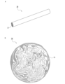
- FIG. 13A is a schematic perspective view of a fiber-reinforced resin pultrusion molded body used for manufacturing a rib-reinforced molded body according to one embodiment of the present invention
- FIG. 13B is a schematic cross-sectional view thereof.
- FIG. 14 is a schematic process diagram showing an example of a method for manufacturing a fiber-reinforced resin pultrusion molded body used for manufacturing the rib-reinforced molded body of one embodiment of the present invention.
- FIG. 15A is a schematic diagram of a fiber sheet folded and fed to the heating section of a pultrusion mold in an example of a method for manufacturing a fiber-reinforced resin pultrusion molded body used for manufacturing a rib-reinforced molded body according to one embodiment of the present invention.
- FIG. 15B is a schematic explanatory diagram showing how a fiber sheet is wound and supplied
- FIG. 15C is a schematic diagram where a plurality of fiber sheets cut into strips are laminated and supplied.
- FIG. 16 is a schematic perspective view of a rib-reinforced molded body according to another embodiment of the present invention.
- FIG. 17 is a schematic partially enlarged sectional view of the rib-reinforced molded body shown in FIG. 16.
- FIG. 18 is a schematic process diagram illustrating one step of a method for manufacturing a rib-reinforced molded body according to one embodiment of the present invention.
- FIG. 19 is a schematic process diagram illustrating one step of a method for manufacturing a rib-reinforced molded body according to one embodiment of the present invention.
- FIG. 20 is a photograph of the rib-reinforced molded product of Example 3.
- the present invention is a rib-reinforced molded body in which a molded body containing resin and reinforcing ribs are integrally molded. Since the reinforcing ribs contain thermoplastic resin, they can be integrally molded with the material of the molded body body containing resin. Furthermore, since the reinforcing ribs include continuous fibers arranged along the length of the reinforcing ribs as reinforcing fibers, the reinforcing ribs themselves have high strength and rigidity.
- arranged along the length direction of the reinforcing rib means that the length direction of the continuous fibers is along the length direction of the reinforcing rib as a whole, and "arranged along the length direction of the reinforcing rib""Continuous fibers arranged along the longitudinal direction" is not limited to the case where the continuous fibers are arranged linearly along the length direction of the reinforcing rib, but also includes cases where the continuous fibers are arranged in a spiral or zigzag pattern. do.
- the reinforcing ribs are preferably a fiber-reinforced resin pultrusion molded body (hereinafter sometimes abbreviated as "pultrusion molded body") that is pre-molded before integral molding with the material of the molded body body.
- the pultrusion molded body is preferably one in which a fiber sheet is pultruded, the fiber sheet is folded into an amorphous shape, and a resin is filled in and between the folded fiber sheets and integrated.
- a pultrusion molded article is obtained by passing the converged fiber sheet through a die (pultrusion mold).
- the obtained pultrusion molded product has a fiber sheet folded into an amorphous shape inside, and the thermoplastic resin constituting the fiber sheet is melted and filled inside the fiber sheet and between the fiber sheets, thereby creating a matrix. It is a solid molded body made of resin. Filling here means that the thermoplastic resin is impregnated into the fiber sheets and fills the spaces between the fiber sheets.
- the pultrusion molded product formed in this manner has few voids.
- the pultrusion molded body is a molded body with uniform stress without directivity in the cross section perpendicular to the length direction of the pultrusion molded body. Become. Therefore, the pultruded body is suitable as a reinforcing material.
- the fiber sheet is a non-resin-impregnated and/or semi-resin-impregnated semi-preg sheet containing reinforcing fibers and a thermoplastic resin, and is highly flexible, since it has good pultrusion moldability. More preferred is a semi-preg sheet with a thermoplastic powder resin fused to the surface to serve as a matrix. By using the semi-preg sheet, pultrusion moldability is good and continuous pultrusion molding is possible.
- the fiber sheet is more preferably a unidirectional continuous fiber (spread sheet) in which continuous fiber groups (reinforcing fibers) are opened and arranged in parallel in one direction.
- a semi-preg sheet in which a thermoplastic powder resin that becomes a matrix is fused to the fiber surface of the pultrusion molded product.
- the pultrusion method is a versatile molding method that can form pultrusion products of various shapes, has good secondary processability, and is easy to process into parts such as curved linear objects and rivets. .
- the reinforcing fibers constituting the pultrusion molded body may be either short fibers or continuous fibers or both, and among them, carbon fibers, glass fibers, and highly elastic fibers with an elastic modulus of 380 cN/dtex or more It is preferable that the fiber contains at least one kind of continuous fiber selected from continuous fibers.
- the high elastic modulus fiber examples include aramid fiber, especially para-aramid fiber (elastic modulus: 380 to 980 cN/dtex), polyarylate fiber (elastic modulus: 600 to 741 cN/dtex), heterocyclic polymer (PBO, elastic modulus) : 1060-2200cN/dtex) fiber, high molecular weight polyethylene fiber (elastic modulus: 883-1413cN/dtex), polyvinyl alcohol fiber (PVA, strength: 14-18cN/dtex), etc. These fibers are useful as resin-reinforced fibers. Carbon fiber is particularly useful from the viewpoint of weight reduction.
- thermoplastic resin constituting the fiber sheet examples include polyamide resin, polycarbonate resin, polypropylene resin, polyester resin, polyethylene resin, acrylic resin, phenoxy resin, polystyrene resin, polyimide resin, and polyether. Ether ketone resins, polyphenylene sulfide resins, and the like can be used, but are not limited to these. From the viewpoint of moldability of the rib-reinforced molded body, the thermoplastic resin constituting the fiber sheet is preferably a thermoplastic resin having a higher softening point than the resin constituting the molded body.
- the reinforcing rib is at least one rod selected from the group consisting of a square rod, a round rod, a flat rod, and a plate rod.
- the cross section of the pultrusion molded body can have various shapes depending on the die shape used in the manufacturing process of the pultrusion molded body.
- the molded body may be formed only from resin, but preferably contains reinforcing fibers from the viewpoint of improving the strength and rigidity of the rib-reinforced molded body.
- the reinforcing fibers may be either or both of short fibers and continuous fibers.
- the resin contained in the molded body may be either a thermosetting resin or a thermoplastic resin, but a thermoplastic resin is preferable.
- thermoplastic resins include polyamide resins, polycarbonate resins, polypropylene resins, polyester resins, polyethylene resins, acrylic resins, phenoxy resins, polystyrene resins, polyimide resins, and polyether ether ketone resins.
- the blending ratio of the resin and the reinforcing fibers is preferably 20 to 65 vol%, with the volume ratio (Vf) of the fibers being 20 to 65 vol%, with the thermoplastic resin
- the volume ratio of the fiber is 35 to 80 volume %, more preferably the volume ratio of the fiber (Vf) is 25 to 60 volume %, and the volume ratio of the thermoplastic resin is 40 to 75 volume %.
- the reinforcing fibers include at least one type of fiber selected from carbon fibers, glass fibers, and high elastic modulus fibers having an elastic modulus of 380 cN/dtex or more.
- a specific example of the high elastic modulus fiber is the same as the high elastic modulus fiber described as an example of the reinforcing fiber.
- the molded body may be formed by laminating and integrating one or more fiber-reinforced resin sheets containing the reinforcing fibers.
- the fiber-reinforced resin sheet which is the material of the molded body, may be either a prepreg sheet or a semi-preg sheet, but from the viewpoint of achieving both thinness and high strength of the rib-reinforced molded body, a continuous fiber group is used. It is preferable to use a semi-preg sheet in which thermoplastic powder resin is fused to the fiber surface of unidirectional continuous fibers (spread sheet), which are opened and arranged in parallel in one direction.From the viewpoint of weight reduction, continuous fibers is preferably carbon fiber.
- the rib-reinforced molded product is preferably a hot press molded product, a vacuum molded product, a pressure molded product, a vacuum pressure molded product, or an injection molded product.
- the reinforcing ribs and the molded body body are formed by, for example, one or more of the following molding methods: hot press molding, vacuum forming, pressure forming, and vacuum-pressure forming. can be integrally molded.
- the above-mentioned molding method is preferably any one of vacuum forming, pressure forming, and vacuum pressure forming, and particularly, vacuum forming is preferable.
- a vacuum is created between a lower mold having a vacuum line and a heated and softened molding material, and the molding material is sucked into the lower mold and brought into close contact with the lower mold (vacuum forming).
- This is a molding method in which a molding material heated and softened by compressed air supplied from an upper mold having a pressure line to a lower mold side is pressed onto a lower mold (pressure-air pressed).
- the resin constituting the semi-preg sheet will be filled in the semi-preg sheets and between the semi-preg sheets to form the molded body.
- the semi-preg sheet becomes the matrix resin of the main body, and the semi-preg sheet becomes the molded body, and the molded body and the reinforcing ribs are integrated.
- the vacuum-pressure forming method allows various shapes to be performed while integrating the molding materials, and is suitable as a method for forming thin-walled molded bodies.
- Injection molding is also called in-mold molding, and has a high molding speed, and can mold thermoplastic resins or thermoplastic resins containing short fibers at high molding speeds.
- the reinforcing ribs are placed on a lower mold having grooves in which the reinforcing ribs can be positioned, and a plurality of semi-preg sheets are laminated on top of the reinforcing ribs.
- the semi-preg sheet may be sandwiched and pressed between a heated lower mold and a heated upper mold. Such a forming method improves the positional accuracy of the reinforcing ribs.
- a laminate in which reinforcing ribs are arranged on a plurality of laminated semi-preg sheets is heated and softened, and the laminate is heated and softened in a lower mold having a vacuum line.
- the method includes vacuum forming the laminate, and pressure-forming the laminate using compressed air supplied from an upper mold having a pressure line to a lower mold.
- a rib-reinforced molded body is formed by a method including the following steps (a) to (d) using a vacuum-pressure forming apparatus including the lower mold, the bagging film, and the upper mold. Manufacture.
- the bagging film is also referred to as a bagging film or a vacuum bag film.
- the laminate is placed in a lower mold such that the semi-preg sheet faces the lower mold.
- the temperature equal to or higher than the softening point is the temperature at which the resin softens or melts.
- a fiber-reinforced resin pultrusion molded body obtained by pultrusion of a fiber sheet is preferably used as the reinforcing rib.
- the fiber sheet is preferably a semi-preg sheet in which a thermoplastic powder resin is fused to the surface of unidirectional continuous fibers in which a group of continuous fibers are opened and arranged in parallel in one direction.
- the method for producing a fiber-reinforced resin pultrusion molded article preferably, converging the fiber sheet and supplying it to a heating section of a pultrusion mold; Compressing the fiber sheet while heating the thermoplastic resin to a temperature higher than the melting point or resin flow temperature in the heating section, The compressed fiber sheet is molded in the molding section of the pultrusion mold, and then cooled in the cooling section of the pultrusion mold to obtain a pultrusion molded body, and the pultrusion molded body is then molded into the pultrusion molding mold. Including pulling from the mold.
- FIG. 13A is a schematic perspective view of a fiber-reinforced resin pultrusion molded body used in one embodiment of the present invention
- FIG. 13B is a schematic cross-sectional view of the same.
- the pultrusion molded body 30 is a rod-shaped molded body, and the fiber sheet is folded into an amorphous shape in cross section. Further, a thermoplastic resin is filled in and between the fiber sheets and integrated.
- the matrix resin component 31 of the pultrusion molded body 30 is a thermoplastic resin, and is impregnated into the fiber sheet and also filled between the fiber sheets.
- pultrusion marks on the surface of the pultrusion molded body. Further, in the pultrusion molded article, at least some of the fibers constituting the raw material fiber sheet are present on the surface. When the fiber sheet is passed through a die while being converged and pulled out, pultrusion marks remain on the surface of the resulting molded product, allowing it to be determined whether it has been pultruded or not.
- the blending ratio of the resin and reinforcing fibers is preferably 20 to 70 volume % of the reinforcing fibers, when the total is 100 volume %, and the thermoplastic resin is preferably 20 to 70 volume %.
- the volume proportion of the reinforcing fibers is preferably 30 to 80 volume %, more preferably the volume proportion of reinforcing fibers (Vf) is 25 to 60 volume %, and the volume proportion of the thermoplastic resin is 40 to 75 volume %.
- the pultrusion molded body 30 is a continuous product or a product cut into a predetermined length.
- the cross-sectional diameter or thickness of the pultruded body is preferably 0.2 to 15 mm, more preferably 1 to 10 mm.
- the cross-sectional shape can be any shape such as round, square, C-shaped, H-shaped, L-shaped, etc., and the shape can be linear, rod-shaped, plate-shaped, etc.
- the fiber sheet is preferably a semi-preg sheet in which a thermoplastic powder resin, which will become the matrix resin of the pultrusion molded product, is adhered and heat-sealed to the surface of the unidirectional continuous fibers.
- This semi-preg sheet is molded so that the thermoplastic resin on the surface is filled within the fiber sheets and between the fiber sheets.
- the fiber sheet more preferably contains crosslinked fibers intersecting with the unidirectional continuous fibers as a subcomponent, and the thermoplastic resin preferably integrates the unidirectional continuous fibers and the crosslinked fibers.
- the main component of the fibers constituting the fiber sheet is unidirectional continuous fibers that are opened and arranged in parallel in one direction.
- the thermoplastic resin used to form the fiber sheet is preferably a powder, and the thermoplastic powder resin is applied onto the unidirectional continuous fibers and crosslinked fibers, and the thermoplastic resin is thermally melted on or near the surface of the unidirectional continuous fibers. It is preferable that the unidirectional continuous fibers and the crosslinked fibers are integrated. Since this fiber sheet has unidirectional continuous fibers and crosslinked fibers integrated by heat-fused thermoplastic resin, it is easy to handle and has good operability during convergence, drawing, and thermoforming.
- the mass proportion of unidirectional continuous fibers is preferably 75 to 99% by mass, more preferably 80 to 97% by mass, and even more preferably 85% by mass. ⁇ 97% by mass.
- the mass proportion of the crosslinked fibers is preferably 1 to 25% by mass, more preferably 3 to 20% by mass, and even more preferably 3 to 15% by mass. If the mass ratio of each fiber is within the above range, the fiber sheet has high integrity and high tensile strength in the width direction, which is preferable.
- the average length of the crosslinked fibers is preferably 1 mm or more, more preferably 5 mm or more.
- the upper limit of the average length of the crosslinked fibers is preferably 1000 mm or less, more preferably 500 mm or less.
- the fiber sheet has high strength in the width direction and is easy to handle, which is preferable.
- the mass per unit area of the fiber sheet is preferably 10 to 500 g/m 2 , more preferably 20 to 400 g/m 2 , and still more preferably 30 to 300 g/m 2 . When it is within the above range, it is easy to handle the fiber sheet for convergence and pultrusion molding.
- the fiber sheet may also include auxiliary yarns arranged in the other direction with respect to the unidirectional continuous fibers. The auxiliary thread keeps the orientation of the fiber sheet constant. Examples of the auxiliary yarn include glass fiber, aramid fiber, polyester fiber, nylon fiber, and vinylon fiber.
- FIG. 10 is a schematic perspective view of a carbon fiber sheet 1, which is an example of the semi-preg sheet
- FIG. 11 is a schematic cross-sectional view of the carbon fiber sheet 1 shown in FIG.
- crosslinked fibers 3 are arranged in various directions on the surface of the opened unidirectional carbon fiber 2.
- the thermoplastic resin 4 is melted and solidified and attached to the surface of the unidirectional carbon fiber 2 and its vicinity, and the resin 4 is not impregnated into the unidirectional carbon fiber sheet or is only partially impregnated. It is.
- FIG. 10 is a schematic perspective view of a carbon fiber sheet 1, which is an example of the semi-preg sheet
- FIG. 11 is a schematic cross-sectional view of the carbon fiber sheet 1 shown in FIG.
- crosslinked fibers 3 are arranged in various directions on the surface of the opened unidirectional carbon fiber 2.
- the thermoplastic resin 4 is melted and solidified and attached to the surface of the unidirectional carbon fiber 2 and its vicinity, and the resin 4 is not impregnated
- crosslinked fibers 3a and 3b are present on the surface of the unidirectional carbon fiber 2. All of the crosslinked fibers 3a are on the surface of the unidirectional carbon fibers 2. A part of the crosslinked fibers 3b is on the surface of the unidirectional carbon fiber 2, and a part is inside and intersects with the carbon fiber.
- "cross” includes entanglement. For example, some or all of the crosslinked fibers 3 are present within the unidirectional continuous fibers and intersect with the unidirectional continuous fibers in a three-dimensional manner.
- the resin 4 adhesively fixes the crosslinked fibers 3 to the surface of the unidirectional carbon fibers 2. Further, the carbon fiber sheet 1 has a portion to which resin 4 is attached and a portion 5 to which no resin is attached.
- the portion 5 to which the resin is not attached becomes a passage through which the air inside the fiber sheet escapes when the carbon fiber sheet 1 is heated and pultruded, making it easier for the resin on the surface to impregnate the entire inside of the fiber sheet. .
- the resin 4 becomes the matrix resin of the pultrusion molded body.
- FIG. 12 is a schematic process diagram showing the method for manufacturing the semi-preg sheet.
- a group of carbon fiber filaments (tows) 8 are pulled out from a large number of supply bobbins 7 and spread by passing between the spreading rolls 21a to 21j (roll spreading step 23).
- Air opening may be used instead of roll opening.
- the opening roll may be fixed or rotating, or may vibrate in the width direction.
- the opened tow is nipped between nip rolls 9a and 9b, and passed between a plurality of bridge rolls 12a-12b installed between the nip rolls 9a and 9b, and the tension of the tow is adjusted to, for example, per 15,000 rolls (1
- the bridge roll may rotate or vibrate in the width direction.
- the bridge roll is, for example, a plurality of rolls with matte, uneven, or mirror surfaces, and generates crosslinked fibers by bending, fixing, rotating, vibrating, or a combination of carbon fiber filaments.
- 13a-13g are guide rolls.
- crosslinked fibers are generated from the carbon fiber filament group by applying a predetermined tension to the opened carbon fiber filament group, so crosslinked fibers are also generated inside the fiber sheet in the direction across the fiber sheet. This is preferable because it exists and intersects with the unidirectional continuous fibers in a three-dimensional manner.
- dry powder resin 15 is sprinkled on the surface of the spread sheet from the powder supply hopper 14, and is supplied into the heating device 16 in a pressure-free state and heated to melt the dry powder resin 15, and then Cooling.
- dry powder resin 18 is also sprinkled from the powder supply hopper 17 on the back side of the spread sheet, and the dry powder resin 18 is fed into the heating device 19 in a pressure-free state and heated to melt the dry powder resin 18, cooled, and then placed on the winding roll 20. (powder resin application step 25).
- the dry powder resins 15 and 18 are, for example, polyphenylene sulfide resin (melting point: 290°C), and the temperatures in the heating devices 16 and 19 are, for example, +5 to 60°C above the melting point or resin flow temperature of the resin, and the residence time is, for example, Each time is 4 seconds.
- the strength of the carbon fiber sheet in the width direction is increased, and the constituent carbon fibers do not fall apart, allowing it to be handled as a sheet.
- a powder coating method for applying the powder resin, a powder coating method, an electrostatic coating method, a spraying method, a fluidized dipping method, etc. can be adopted.
- a powder coating method in which powdered resin is dropped onto the surface of the spread sheet is preferred.
- powdered resin in the form of dry powder is sprinkled on the spread sheet.
- crosslinked fibers are generated from the carbon fiber filament group by applying a predetermined tension to the spread carbon fiber filament group, but instead of this, the crosslinked fibers are dropped onto the spread sheet. Good too.
- the crosslinked fibers may be present only on one side of the spread sheet, or may be present on both surfaces. If the fiber sheet (semi-preg sheet) does not contain crosslinked fibers, the crosslinked fiber generation step 24 in FIG. 12 may be omitted.
- the pultrusion mold 37 is a pultrusion mold that includes a heating section 34, a forming section 35, and a cooling section 36 in this order along the traveling direction of the fiber sheet.
- the fiber sheet 32 passes through a guide 33, converges, and is supplied to a heating section 34 of a pultrusion mold 37.
- the heating section 34 the fiber sheet 32 is heated to a temperature higher than the melting point or resin flow temperature of the thermoplastic resin present on at least the surface of the fiber sheet 32.
- the resin flow temperature is the temperature at which resin flow begins.
- the fiber sheet is compressed while being pulled out in the traveling direction, and is formed into the shape of the inner cavity of the heating section 34.
- it is drawn into the molding part 35, shaped into the shape of the inner cavity of the molding part 35, and stabilized in that shape within the molding part 35.
- the mold temperature of the molding section 35 is preferably equal to the mold temperature of the heating section 34 .
- it is cooled in the cooling unit 36 to fix the shape.
- the mold temperature of the molding section 35 is, for example, higher than the melting point or resin flow temperature of the thermoplastic resin. It is efficient to use water cooling as the cooling means for the cooling unit 36.
- the obtained pultrusion molded product is pulled out from the pultrusion mold 37 by pultrusion rollers 38a and 38b, and if the molded product is thin, it is rolled up or, if necessary, a fiber-reinforced resin pultrusion molded product 40 of a predetermined length is used with a blade 39. Cut to.
- a matrix resin of the pultrusion molded body is added to the surface of the unidirectional continuous fibers and in the vicinity thereof.
- a fiber sheet (semi-preg sheet) to which a thermoplastic powder resin is fused is used, and the following steps are included.
- one or more fiber sheets are used.
- the fiber sheet is preferably supplied to the heating section in at least one converged state selected from a folded state, a rolled state, and a state in which strip-shaped sheets are stacked.
- the planar fiber sheet can be brought close to a three-dimensional molded body such as a rod shape, and in the obtained pultrusion molded body, the fiber sheet is folded into an amorphous shape.
- convergence refers to gathering or bundling the fiber sheets into a moldable state. For example, the above-mentioned folding, winding, stacking of strip-shaped sheets, etc. are included.
- FIG. 15A shows a fiber sheet 41 in a folded state
- FIG. 15B shows a fiber sheet 42 in a rolled state
- FIG. 15C shows a fiber sheet 43 in a state in which strip-shaped fiber sheets are laminated.
- the fiber sheet 42 may be wound diagonally.
- a guide 33 FIG. 14 or the like can be used as a means for converging the fiber sheet 32.
- the orientation direction of the fibers can be set at an arbitrary angle.
- the rolled sheet When using a rolled fiber sheet, the rolled sheet may be further wound. Winding is possible at any angle.
- the fiber sheets may be laminated, and can be laminated at any angle such as 0°, 45°, or 90°. Usually, it is based on a fiber sheet with a length direction (one direction) of 0°. 0° means that the length direction of the unidirectional continuous fibers of the fiber sheet and the drawing direction of pultrusion molding (length direction of the molded object) are the same direction.
- the amount of insertion of the semi-preg sheet into the pultrusion mold can be changed depending on the target diameter of the pultrusion molded body and the mass per unit length.
- the heating temperature of the fiber sheet (the mold temperature of the heating section 34) is, for example, a temperature equal to or higher than the resin melting temperature, and the drawing speed is preferably 10 mm to 100 m/min. Melting of thermoplastic resin, impregnation between fibers, and molding can be controlled by two conditions: temperature and drawing speed.
- the shape of the internal space of the heating section 34 is preferably a tapered shape, a trumpet shape, etc. in which the diameter decreases in the direction of travel of the fiber sheet.
- the inlet diameter (D1) of the heating section 34 is larger than the target diameter of the pultruded body, and the outlet diameter (D2) of the heating section and the diameter (D3) of the forming section are the same as the target diameter.
- the exit diameter (D2) of the heating section 34 and the diameter (D3) of the molding section 35 are, for example, 1 to 15 mm.
- the ratio of the inlet diameter (D1) of the heating part 34 to the outlet diameter (D2) of the heating part 34 is preferably 1.5 times or more, more preferably 2 times or more, and still more preferably 2.5 times or more. Although there is no upper limit for D1/D2, practically it is preferably 10 times or less, more preferably 8 times or less.
- the fiber sheet 32 that is the material of the pultrusion molded body is compressed in the heating section 34 by a pulling force, in other words, it is compressed while being pulled out in the advancing direction.
- the diameter (D4) of the mold of the cooling section 36 is preferably the same as the exit diameter (D2) of the mold of the heating section 34 and the diameter (D3) of the molding section 35.
- the steps from the supplying step to the drawing step are continuous. If it is a continuous process, manufacturing efficiency is high and manufacturing costs can be reduced.
- the elongated pultrusion molded product obtained after the cooling step can be continuously rolled up or cut into a predetermined length as long as it is thin enough to be rolled up.
- the method for manufacturing a pultrusion molded article according to one embodiment described above is characterized in that a semi-preg sheet is directly molded.
- the fiber sheet (semi-preg sheet) used is flexible and has excellent shapeability, and can be inserted into the heating section 34 as it is, eliminating the need for preheating.
- prepreg since prepreg is hard, it cannot be folded as it is.
- thermoplastic resin in which fiber bundles are bound with a binding material and dipped in a thermoplastic resin solution to make a wire rod, there are restrictions on the selection of thermoplastic resin.
- thermoplastic resin powder is dropped onto the fiber surface of unidirectional continuous fibers (spread sheet) and welded and solidified, so that the pultrusion molded article It can be said that heating and melting of the resin during molding and subsequent cooling can be performed efficiently, and that the moldability of the pultrusion molded product is good and the molding speed is high.
- the fiber reinforced resin sheet is the material of the molded body.
- the fiber-reinforced resin sheet is preferably a non-resin-impregnated and/or semi-resin-impregnated semi-preg sheet containing fibers and a thermoplastic resin and having high flexibility.
- the fiber-reinforced resin sheet is more preferably made of unidirectional continuous fibers (spread sheet) in which continuous fiber groups are opened and arranged in parallel in one direction.
- thermoplastic powder resin becomes a matrix (base material) resin of the molded body during molding of the rib-reinforced molded body, and joins the molded body and the reinforcing ribs to integrate them.
- the fiber reinforced resin sheet may further contain crosslinked fibers intersecting with the unidirectional continuous fibers as a subcomponent, in which case the thermoplastic resin integrates the unidirectional continuous fibers and the crosslinked fibers. It is preferable that the The semi-preg sheet that becomes the main body of the molded body by molding the rib-reinforced molded body is as shown in FIG.
- the fiber-reinforced resin sheet does not contain crosslinked fibers, the crosslinked fiber generation step 24 in FIG. 12 may be omitted. Further, the fiber-reinforced resin sheet can be manufactured by the method for manufacturing a resin-integrated fiber sheet disclosed in WO2021/095626.
- the thermoplastic resin contained in the fiber-reinforced resin sheet is preferably a thermoplastic resin having a softening point lower than that of the thermoplastic resin constituting the pultrusion molded body.
- the volume ratio (Vf) of fibers is preferably 20 to 65 volume %, the ratio of thermoplastic resin is 35 to 80 volume %, and more preferably the volume ratio (Vf) of fibers is 25 to 60 volume %. %, the proportion of thermoplastic resin is 40 to 75% by volume.
- the resin component of the fiber-reinforced resin sheet can be used as the matrix resin component of the molded body, and the reinforcing ribs and the molded body can be integrated, and when manufacturing the rib-reinforced molded body, new resin It is not necessary to add .
- the mass proportion of the unidirectional continuous fibers is preferably 75 to 99% by mass, more preferably It is 80 to 97% by weight, more preferably 85 to 95% by weight. Further, the mass proportion of the crosslinked fibers is preferably 1 to 25% by mass, more preferably 3 to 20% by mass, and still more preferably 5 to 15% by mass. If the mass ratio of each fiber is within the above range, the fiber-reinforced resin sheet has high integrity and high tensile strength in the width direction, which is preferable.
- the average length of the crosslinked fibers is preferably 1 mm or more, more preferably 5 mm or more.
- the upper limit of the average length of the crosslinked fibers is preferably 1000 mm or less, more preferably 500 mm or less. If the average length of the crosslinked fibers is within the above range, the fiber-reinforced resin sheet has high strength in the width direction and is excellent in handleability, which is preferable.
- the mass per unit area of the fiber-reinforced resin sheet is preferably 10 to 3000 g/m 2 , more preferably 20 to 2000 g/m 2 , and still more preferably 30 to 1000 g/m 2 .
- the thickness of one fiber reinforced resin sheet is preferably 0.01 to 5.0 mm.
- a fiber-reinforced resin sheet with a thickness within this range is easy to vacuum-pressure form.
- the preferred number of fiber-reinforced resin sheets to be laminated is 2 to 70, more preferably 2 to 50.
- FIG. 1A to 1C are schematic cross-sectional views of a rib-reinforced molded body according to one embodiment of the present invention.
- FIG. 1A shows a rib-reinforced molded body 51a in which reinforcing ribs 53 are arranged on one main surface (lower surface) of a molded body 52 containing resin or resin and reinforcing fibers (short fibers).
- FIG. 1B shows a rib-reinforced molded body 51b in which a part of the reinforcing ribs 53 is embedded inside the molded body 52, and the remainder of the reinforcing ribs 53 protrudes from one main surface (lower surface) of the molded body 52.
- FIG. 1C shows a rib-reinforced molded body 51c in which a part of the reinforcing ribs 53 is embedded inside the molded body 52, and the remainder of the reinforcing ribs 53 protrudes from the other main surface (upper surface) of the molded body 52. .
- the reinforcing ribs 53 are integrated into the molded body 52.
- two or more of the embodiments shown in FIGS. 1A to 1C can be used in combination.
- the entire reinforcing rib may be embedded inside the molded body 52.
- FIG. 2 is a schematic back view of a rib-reinforced molded body 51d according to another embodiment of the present invention.
- the rib-reinforced molded body 51d includes reinforcing ribs 53a to 53c integrally molded to the molded body 52, and the reinforcing ribs 53a to 53c are arranged parallel to each other on the back surface of the molded body 52.
- FIG. 3 is a schematic back view of a rib-reinforced molded body 51e according to still another embodiment of the present invention.
- the rib-reinforced molded body 51e includes reinforcing ribs 53a and 53b integrally molded on the molded body 52, and the reinforcing ribs 53a and 53b intersect on the back surface of the molded body 52.
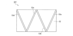
- FIG. 4 is a schematic back view of a rib-reinforced molded body 51f according to still another embodiment of the present invention.
- the rib-reinforced molded body 51f includes reinforcing ribs 53a to 53d integrally molded to the molded body 52, and the reinforcing ribs 53a to 53d are arranged in a W-shape on the back surface of the molded body 52.
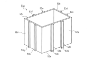
- FIG. 5 is a schematic back view of a rib-reinforced molded body 51g (casing) of still another embodiment of the present invention.
- the rib-reinforced molded body 51g is a casing, and includes a box-shaped molded body consisting of a bottom portion 52e and side portions 52a to 52d.
- the rib-reinforced molded body 51g includes reinforcing ribs 53a-53j integrally molded on the molded body. Two reinforcing ribs are arranged parallel to each other on the outer surfaces of the bottom portion 52e and the side portions 52a-52d, respectively.
- FIG. 6 is a schematic cross-sectional view of a vacuum-pressure forming apparatus used in the method for manufacturing a rib-reinforced molded product according to one embodiment of the present invention, and FIGS. It is a typical process diagram explaining each process of a manufacturing method.
- the vacuum-pressure forming apparatus 60 includes a lower mold 63 having a vacuum line 64 and an upper mold 69 having a pressure line 70.
- the lower mold 63 is fixed on a base 61 and a mold stand 62, and a vacuum line 64 extends to a molding surface 65.
- a vacuum pump (not shown) is connected to the vacuum line 64.
- the upper mold 69 includes an upper mold main body 66 including a pressurizing line 70, and can supply compressed air downward (toward the lower mold 63) from the air groove 67 and the air hole 71 of the face plate 68.
- a compressor (not shown) is connected to the pressurizing line 70.
- the lower mold 63 is heated and cooled by an electromagnetic induction heating type, resistance wire heating type, infrared heating type, or wire heating type heater 72 and a water cooling pipe 73, and can be controlled to a predetermined temperature.
- FIG. 7 shows the preparation process
- FIG. 8A shows the heating and temperature raising process
- FIG. 8B shows the heating vacuum pressure forming process
- FIG. 8C shows the cooling and demolding process.
- a laminate 90 in which a plurality of semi-preg sheets 10 are laminated on the molding surface 65 of the lower mold 63 and reinforcing ribs 30 are arranged on top of the semi-preg sheets 10 is placed on the molding surface 65 of the lower mold 63. I'll put it on.
- the laminate 90 is placed so that the semi-preg sheet 10 faces the molding surface 65.
- the lower mold 63 is covered with a bagging film 74 to form a closed space that can be under a vacuum atmosphere below the bagging film 74.
- an upper mold 69 is placed on the bagging film 74.
- the air inside the lower mold 63 (inside the closed space) is sucked through the vacuum line 64 to reduce the pressure in the closed space, and the laminate 90 is sucked toward the lower mold 63. It is brought into close contact with the mold 63.
- the lower mold 63 is heated by a heater 72 .
- the temperature increase of the lower mold 63 may be started at the same time as the start of pressure reduction, but may be raised either before or after the start of pressure reduction.
- the laminate 90 is heated to a temperature equal to or higher than the softening point of the thermoplastic resin constituting the semi-preg sheet 10 to soften the thermoplastic resin.
- the obtained molded body is cooled while maintaining the pressure conditions in FIG. 8B, and after cooling, the pressure applied to the closed space is released, and the rib reinforced molded body 50 (vacuum pressure molded body).
- the degree of reduced pressure (degree of vacuum) in the closed space due to exhaust from the vacuum line 64 of the lower mold 63 is preferably 0 to 0.1 MPa, and the air pressure of compressed air supplied from the pressurizing line 70 of the upper mold 69 is 0.1 MPa. 1 to 2.0 MPa is preferable.
- a fluororesin film such as polytetrafluoroethylene, a thermal film such as a polyimide resin film, or a silicone rubber sheet can be used.
- the advantages of the method for producing a rib-reinforced molded body according to this embodiment are as follows. (1) Since a semi-preg sheet containing unidirectional continuous fibers (spread sheet) and thermoplastic resin is used as the material for the molded body 10, the molded body 10 is thin, has high strength, and has good shapeability. An excellent rib-reinforced molded product can be obtained.
- direct molding is possible. That is, the laminate 90 can be shaped without preheating (preheating for softening the molding material before placing it in the molding die), and the shaping and resin spread sheet can be performed. The entire filling (impregnation) can be done almost simultaneously. (2) Since direct molding is possible, the thermal history of the resin can be reduced and deterioration of the resin can be prevented. (3) Since the vacuum-pressure forming method uses a bagging film, it is possible to form not only flat shapes but also various three-dimensional shapes.
- FIG. 9A shows an in-mold (injection) molding device 80 used in the method for manufacturing a rib-reinforced molded body of this embodiment.
- the molding device 80 includes an upper mold 81 and a lower mold 82.
- the upper mold 81 and the lower mold 82 are placed apart, but the gap created when these are aligned and overlapped is a cavity.
- Grooves 83a-83c for positioning reinforcing ribs are formed on the surface of the lower mold 82 constituting the cavity.
- 84 is an injection port for molten resin.
- Reinforcing ribs 85a-85c are arranged in the grooves 83a-83c as shown in FIG. 9B.
- the upper mold and the lower mold are aligned and overlapped, and then molten resin 86 is injected from the injection port 84.
- the molten resin is molded into a molded body 87 in a cavity formed between the upper mold 81 and the lower mold 82, and is integrated with the reinforcing ribs 85a-85c.
- the molded body is a laminated base material in which base material layers containing a plurality of resins are laminated, and the reinforcing ribs are arranged inside the laminated base material.
- This is a rib member made of aluminum.
- the rib-reinforced molded body has a structure in which a protrusion corresponding to the outer shape of the rib member disposed inside the laminated base material is formed on one main surface thereof.
- the rib-reinforced molded article of the present invention includes a laminated base material in which a plurality of base material layers are laminated, reinforcing fibers and a thermoplastic resin, and ribs arranged inside the laminated base material.
- the reinforcing fibers include continuous fibers arranged along the length direction of the reinforcing ribs, and a protruding strip corresponding to the outer shape of the rib member is formed on one main surface. Since the rib member contains reinforcing fibers, the strength and rigidity of the ridges are high, and therefore the strength and rigidity of the rib-reinforced molded body are also high. Furthermore, since the protrusions have high strength and rigidity, even if the laminated base material is made thinner, it is possible to provide a rib-reinforced molded body with high strength and rigidity.
- the rib member is preferably a fiber-reinforced resin pultrusion molded article containing reinforcing fibers and a thermoplastic resin.
- the pultrusion molded body the same one as described in [Embodiment 1] can be used.
- the fiber sheet used to form the pultrusion molded body, the reinforcing fibers and thermoplastic resin constituting the fiber sheet, the shape of the pultrusion molded body, the method for manufacturing the pultrusion molded body, etc. are as described in [Embodiment 1] ] It is the same as that explained in .
- the thermoplastic resin constituting the fiber sheet is preferably a thermoplastic resin having a higher softening point than the resin constituting the base layer.
- the base sheet which is the material of the base layer constituting the laminated base material, is not particularly limited, and examples include resin sheets, fiber-reinforced resin sheets containing reinforcing fibers, metal sheets, cellulose sheets, etc. , preferably at least one resin-containing sheet selected from resin sheets and fiber-reinforced resin sheets containing reinforcing fibers.
- the resin-containing sheet is not particularly limited as long as it can be integrally molded with the rib member, but from the viewpoint of molding a high-strength rib-reinforced molded body, a fiber-reinforced resin sheet is more preferable.
- the resin contained in the base layer and the resin-containing sheet may be either a thermosetting resin or a thermoplastic resin, but a thermoplastic resin is preferable.
- thermoplastic resins include polyamide resins, polycarbonate resins, polypropylene resins, polyester resins, polyethylene resins, acrylic resins, phenoxy resins, polystyrene resins, polyimide resins, and polyether ether ketone resins. Usable include, but are not limited to:
- the resin-reinforced resin sheet is made of the fiber-reinforced resin that is the material of the molded body described in [Embodiment 1]. The same thing as the sheet can be used.
- the rib-reinforced molded product of this embodiment is preferably a hot press molded product, a vacuum molded product, a pressure molded product, or a vacuum pressure molded product, and is processed by a hot press molding method, a vacuum forming method, a pressure forming method, and a vacuum pressure molding method.
- the rib-reinforced molded body of this embodiment can be manufactured by integrally molding the rib member and a plurality of base sheets using any one of these molding methods.
- the above-mentioned molding method is preferably any one of vacuum forming, pressure forming, and vacuum pressure forming, and particularly, vacuum forming is preferable. According to the vacuum-pressure forming method, various shapes can be performed while integrating constituent materials, and it is suitable as a method for forming thin-walled molded objects.
- a laminate in which a plurality of resin-containing sheets are laminated and a rib member is arranged between any one of the plurality of resin-containing sheets is heated.
- the laminate is softened and vacuum-formed in a lower mold having a vacuum line, and the laminate is pressure-formed with compressed air supplied from the upper mold to the lower mold.
- a rib-reinforced molded body is formed by a method including the following steps (a) to (d) using a vacuum-pressure forming apparatus including the lower mold, the bagging film, and the upper mold. Manufacture.
- Step of pressing the laminate against the lower mold side a step of vacuum-pressure forming the laminate
- the temperature above the softening point is the temperature at which the resin softens or melts. be.
- the resin-containing sheet is preferably a fiber-reinforced resin sheet, and the thickness of one fiber-reinforced resin sheet is preferably 0.01 to 5.0 mm.
- a fiber-reinforced resin sheet with a thickness within this range is easy to vacuum-pressure form.
- the preferred number of fiber-reinforced resin sheets to be laminated is 5 to 70, more preferably 8 to 50.
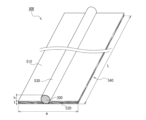
- FIG. 16 is a schematic perspective view of a rib-reinforced molded body 500 according to one embodiment of the present invention
- FIG. 17 is a schematic partial enlarged sectional view of the rib-reinforced molded body 500 shown in FIG. 16.
- the rib-reinforced molded body 500 is a plate-shaped body in which a protruding strip 530 is formed on one main surface 510.
- a rib member 300 is arranged as a reinforcing rib inside a laminated base material 540 including a plurality of base material layers 520, for example, on one main surface 510 side.
- the rib member 300 is disposed between the second and third base material layers 520, and the rib member 300 and the plurality of base material layers 520 are laminated and integrated.
- the base material layer 520 disposed closer to one main surface 510 than the rib member 300 covers the rib member 300 along the outer peripheral surface of the rib member 300.
- a protruding strip 530 corresponding to the outer shape of the rib member 300 is formed as a rib on one main surface 51. Since the rib member 300 is disposed between the base material layers 520, it is not exposed on the surface of the rib-reinforced molded body 500, but is embedded within the rib-reinforced molded body 500.
- the base material layer 520 and the rib member 300 contain thermoplastic resin, in the manufacturing process of the rib-reinforced molded body 500, the resin-containing sheets 100 (see FIG. 18B) that become the base material layer 520 through molding are laminated and integrated. It is possible to integrally mold the rib member 300 and the resin-containing sheet 100. Since the protruding strip 530 is a protruding strip formed corresponding to the outer shape of the rib member 300 containing reinforcing fibers, the protruding strip 530 itself has high strength and rigidity. Therefore, the rib-reinforced molded body 500 has improved strength and rigidity by including the rib member 300 therein.
- the number of base material layers 520 there is no particular restriction on the number of base material layers 520, but the preferred number of layers is 5 to 70, more preferably 8 to 50. There is no particular restriction on the arrangement position of the rib member 300 in the laminated base material layer 520.
- the rib member 300 is a pultrusion molded body, the pultrusion marks and fibers on the surface of the pultrusion molded body, and the fibers constituting the fiber reinforced resin sheet forming the base material layer 520 are hidden with resin, and the rib reinforced molded body 500 is From the viewpoint of improving the smoothness of one surface, it is preferable that the rib member 300 is disposed two or more layers below the one main surface side on which the protruding stripes 530 are formed.
- the direction of the unidirectional continuous fibers may be changed. It may also be laminated.
- the direction of the unidirectional continuous fibers can be changed such as 0°/45°/90°/135°/180°/..., 0°/90°/180°/..., etc. As a result, a molded article having the required mechanical properties can be obtained.
- the rib-reinforced molded body 500 includes one rib member 300, there is no particular restriction on the number of rib members 300, and depending on the size, shape, application, required strength, etc. of the rib-reinforced molded body 500, You can decide as appropriate.
- the rib-reinforced molded body 500 may include a plurality of rib members, the plurality of rib members may be arranged parallel to each other, or the other rib members may be inclined relative to one rib member, and the rib-reinforced molded body 500 may May include braces.
- a method for manufacturing the rib-reinforced molded body 500 shown in FIGS. 16 and 17 will be described as an example. Since the method for manufacturing a rib-reinforced molded body according to this aspect also uses the vacuum-pressure forming apparatus 60 described in [Embodiment 1], a description of the vacuum-pressure forming apparatus 60 will be omitted.
- the manufacturing method of the rib-reinforced molded body 500 of this embodiment is similar to that shown in FIGS. 7 and 8 in [Embodiment 1] except that the laminate 900 shown in FIG. 18B is used instead of the laminate 90 shown in FIG. 7B. This method is the same as the manufacturing method of the rib-reinforced molded body explained using.
- a plurality of resin-containing sheets 100 are stacked on the molding surface 65 of the lower mold 63, and a rib member 300 is arranged between any one of the plurality of resin-containing sheets 100.
- laminate 900 (see FIG. 18B) is placed thereon. At this time, the laminate 900 is placed on the molding surface 65 so that the rib member 300 is far from the molding surface 65.
- the lower mold 63 is covered with a bagging film 74 to form a closed space that can be under a vacuum atmosphere below the bagging film 74. Further, an upper mold 69 is placed on the bagging film 74.
- the air inside the lower mold 63 (inside the closed space) is sucked through the vacuum line 64 to reduce the pressure in the closed space, and the laminate 900 is sucked toward the lower mold 63, and It is brought into close contact with the mold 63.
- the lower mold 63 is heated by a heater 72 .
- the temperature increase of the lower mold 63 may be started at the same time as the start of pressure reduction, but may be raised either before or after the start of pressure reduction.
- the pre-laminated body 900 is heated to a temperature equal to or higher than the softening point of the thermoplastic resin constituting the resin-containing sheet 100 to soften the thermoplastic resin.
- the preferable degree of reduced pressure (degree of vacuum) of the closed space due to exhaust from the vacuum line 64 of the lower mold 63 and the preferable air pressure of the compressed air supplied from the compressed air pipe 70 of the upper mold 69 are respectively [Embodiment 1] It is the same as that in .
- the bagging film 74 used can also be the same as that in [Embodiment 1].
- the advantages of the method for manufacturing a rib-reinforced molded body according to one embodiment of the present invention are as follows. (1) Since the rib member, which has high strength and rigidity due to the inclusion of reinforcing fibers, is embedded in the molded body, it is possible to provide a rib-reinforced molded body that has high strength and rigidity even if the laminated base material is thinned. (2) In particular, if a fiber-reinforced resin sheet (semi-preg) containing continuous fibers is used as the resin-containing sheet 100, a rib-reinforced molded body that is thin but has high strength and excellent shapeability can be obtained. In addition, direct molding is possible.
- the laminate 900 can be shaped without preheating (preheating for softening before placement in a molding die), and the shaping and the entire fiber-reinforced resin sheet of the resin can be performed. Filling (impregnation) can be done almost simultaneously.
- the thermal history of the resin can be reduced and deterioration of the resin can be prevented.
- Three-dimensional shapes can also be formed.
- Example 1 Vacuum pressure forming method
- Unopened carbon fiber tow The unopened carbon fiber tow was manufactured by Mitsubishi Chemical Corporation, product number: PYROFILE TR 50S15L, shape: regular tow, filament 15K (15,000 filaments), and single fiber diameter 7 ⁇ m.
- An epoxy compound is attached as a sizing agent to the carbon fibers of this unopened carbon fiber tow.
- Spreading means for unopened tow The fibers were opened using the opening means shown in FIG. 12. In the crosslinked fiber generation step, the tension of the carbon fiber filament group (tow) was 15 N per 15,000 filaments.
- the unspread tow was made into a spread sheet having 15K carbon fiber filaments, a spread width of 500 mm, and a thickness of 0.08 mm.
- the crosslinked fiber content was 3.3% by mass.
- the average particle size of the dry powder resin was 350 ⁇ m.
- This resin powder was applied in an average of 29.7 g on one side and 59.4 g on both sides to 1 m 2 of carbon fiber (the above-mentioned spread sheet).
- the temperatures in the heating devices 16 and 19 were each 380° C., and the residence time was 4 seconds each.
- the mass of the obtained semi-preg sheet (fiber sheet) was 139.6 g/m 2
- the volume ratio of fiber (Vf) was 50 volume %
- the volume ratio of PPS resin was 50 volume %.
- a pultrusion molded body was formed using the pultrusion processing apparatus shown in FIG. -
- the insertion width of the semi-preg sheet (fiber sheet) was set to 20 mm, and the sheet was folded arbitrarily and supplied to the heating section 34 of the mold.
- the semi-preg sheet heated, compressed and molded in the heating section 34 was passed through the heated molding section 35 to stabilize its shaping and shape.
- the formed semi-preg sheet was cooled in the cooling section 36 to fix its shape.
- the obtained molded body was wound up by a winding machine having a curvature that allows winding.
- the mold temperature of the heating section 34 and the molding section 35 was 400° C.
- the mold temperature of the cooling section 36 (water cooling) was 15° C.
- the drawing speed was 72 mm/min.
- the obtained pultrusion molded product (CFRTP) had a substantially circular cross section and a lot shape with a diameter of 2.5 mm.
- the crosslinked fiber content was 3.3% by mass.
- PA12 resin powder (polyamide 12, melting point: 176°C, manufactured by Ube Industries, Ltd.) was used as the dry powder resin.
- the average particle size of the dry powder resin was 340 ⁇ m.
- This resin powder was applied in an average of 22.5 g on one side and 45.0 g on both sides to 1 m 2 of carbon fiber (the spread sheet).
- the temperatures in the heating devices 16 and 19 were each 240° C., and the residence time was 4 seconds each.
- the mass of the obtained semi-preg sheet (fiber-reinforced resin sheet) was 125 g/m 2
- the volume ratio of fibers (Vf) was 50 volume %
- the volume ratio of PA12 resin was 50 volume %.
- Example 2 Vacuum-pressure forming
- the rib-reinforced molded body of Example 1 was produced using the vacuum-pressure forming apparatus shown in FIGS. 6 to 8 according to the following procedure.
- - Step 1 A laminate of a semi-preg sheet and the above CFRTP was placed on a nickel alloy lower mold according to the above "(1) Lamination conditions". At that time, the above laminate was placed in the lower mold so that the semi-preg sheet faced the lower mold, and later the CFRTP faced the upper mold.
- a bagging film was placed thereon to form a closed space that could be placed under a vacuum atmosphere between the bagging film and the lower mold.
- a silicone rubber sheet with a thickness of 2 mm was used as the bagging film.
- Step 2 The closed space was depressurized from the vacuum line of the lower mold to a degree of decompression of 0.09 MPa, and at the same time as the start of depressurization, the temperature of the lower mold was started to rise.
- ⁇ Process 3 After the lower mold temperature reaches 205°C (molding temperature), the laminate is pressurized at 0.70 MPa with compressed air from above the bagging film, the pressurized state is maintained for 3 minutes, and then vacuum pressure is applied. Molded. Step 3 was performed while maintaining the pressure conditions of Step 2.
- - Step 4 The lower mold was cooled to 50° C. while maintaining the pressure conditions of Step 3, and then the vacuum line and the pressure line were shut off, and the obtained vacuum-pressure molded product was demolded. One cycle of steps 1 to 4 was 400 seconds. The obtained vacuum-pressure molded body was integrally formed with the molded body and the reinforcing ribs.
- the rib-reinforced molded body of Example 1 is a substantially plate-shaped body including one reinforcing rib, and the length of the molded body body is 300 mm, the width is 300 mm, and the thickness (wall thickness). was 1 mm.
- the height of the reinforcing ribs from the surface of the molded body (the surface from which the reinforcing ribs protruded) was 2.5 mm.
- This vacuum-pressure molded product had no warpage, and the strength and rigidity of the reinforcing ribs were high, so the strength and rigidity of the rib-reinforced molded product were also high.
- Example 2 In-mold molding
- the rib-reinforced molded body of Example 2 was produced using an in-mold (injection) molding apparatus shown in FIGS. 9A to 9C. Specifically, reinforcing ribs are placed in grooves formed on the surface of the lower mold that constitutes the cavity, and then the upper and lower molds are aligned and overlapped, and heated to 220°C to melt them. The prepared polypropylene resin (melting point: 160°C) was injected into the cavity from the injection port. Thereafter, the upper mold and the lower mold were water-cooled to cool the mold to 30° C., and then the rib-reinforced molded product (injection molded product) was taken out.
- injection molding apparatus shown in FIGS. 9A to 9C. Specifically, reinforcing ribs are placed in grooves formed on the surface of the lower mold that constitutes the cavity, and then the upper and lower molds are aligned and overlapped, and heated to 220°C to melt them. The prepared polypropylene resin (melting point:
- the molded body and the reinforcing ribs were integrally molded.
- the length of the molded body was 300 mm
- the width was 300 mm
- the thickness (wall thickness) was 1 mm.
- a part of the reinforcing ribs is embedded in the molded body, and the rest protrudes outward from one main surface (lower surface) of the molded body, and The height of the reinforcing ribs from the surface (the side surface from which the reinforcing ribs protruded) was 2 mm.
- This molded product had no warpage and the reinforcing ribs had high strength and rigidity, so the strength and rigidity of the molded product were also high.
- Example 3 Vacuum pressure forming method, rib member embedding type
- Example 3 Vacuum-pressure forming
- the rib-reinforced molded body of Example 3 was produced using the vacuum-pressure forming apparatus shown in FIGS. 6 to 8 according to the following procedure.
- - Step 1 A laminate of a semi-preg sheet and the above CFRTP was placed on a nickel alloy lower mold according to the above "(1) Lamination conditions". At that time, the laminate was placed in the lower mold so that the first semi-preg sheet from the bottom in FIG. 18B faced the lower mold.
- a bagging film was placed over the lower mold to form a closed space that could be placed under a vacuum atmosphere between the bagging film and the lower mold.
- a silicone rubber sheet with a thickness of 2 mm was used as the bagging film.
- Step 2 The closed space was depressurized from the vacuum line of the lower mold to 0.09 MPa, and the temperature of the lower mold was started to increase at the same time as the start of depressurization.
- ⁇ Process 3 After the lower mold temperature reaches 205°C (molding temperature), the laminate is pressurized at 0.70 MPa with compressed air from above the bagging film, the pressurized state is maintained for 3 minutes, and then vacuum pressure is applied. Molded. Step 3 was performed while maintaining the pressure conditions of Step 2.
- Step 4 The lower mold was cooled to 50° C. while maintaining the pressure conditions of Step 3, and then the vacuum line and the pressure line were shut off, and the obtained vacuum-pressure molded product was demolded. One cycle of steps 1 to 4 was 400 seconds.
- FIG. 20 is a photograph of the rib-reinforced molded body of Example 3 produced as described above, the right figure is a photograph taken from one main surface side, and the left figure is a photograph taken from the other main surface side. This is a photo I took.
- the height h of the rib-reinforced molded body of Example 3 was 2 mm, the width w was 30 mm, the thickness (thickness) t was about 1 mm, and the length L was 300 mm (see FIG. 1).
- This molded body does not warp, and the ridges are formed by embedding a pultrusion molded body containing reinforcing fibers inside.
- the strength and rigidity of the protrusions themselves are high, and therefore the strength and rigidity of the rib-reinforced molded body are also high.
- the rib-reinforced molded product of the present invention has high strength in the reinforcing rib itself, so the rib-reinforced molded product has a high reinforcing effect on the molded product body, and is useful for various uses such as frames, plates, shelves, walls, and housings. It is. Furthermore, it can be widely applied in aviation, space, automobiles, sports, three-dimensional printers, industrial applications, building materials, windmills, bicycles, railways, ships, etc.
- Carbon fiber sheet 2 Unidirectional carbon fibers 3, 3a, 3b Crosslinked fibers 4 Resin 5 Portion to which resin is not attached 6
- Supply bobbin 8 Carbon fiber filament group (carbon fiber unspread tow) 9a, 9b Nip roll 10 Fiber reinforced resin sheet (semi-preg sheet) 12a-12b Bridge rolls 13a-13g Guide rolls 14, 17 Powder supply hoppers 15, 18 Dry powder resin 16, 19 Heating device 20 Winding rolls 21a-21j Spreading roll 23 Roll opening process 24 Crosslinked fiber generation process 25 Powder Resin application step 30, 40 Fiber-reinforced resin pultrusion molded body 31 Thermoplastic resin impregnated integral cross section 32, 41-43 Fiber sheet 33 Guide 34 Heating section 35 Molding section 36 Cooling section 37 Molding mold 38a, 38b Drawing roller 39 Blade 51a-51g Rib reinforced molded body 52 Molded body body 53a-53j Reinforcement rib 60 Vacuum pressure forming device 64 Vacuum line 63 Lower mold 69 Upper mold 70 Pressure line 80 In-mold (injection),
Landscapes
- Engineering & Computer Science (AREA)
- Mechanical Engineering (AREA)
- Chemical & Material Sciences (AREA)
- Composite Materials (AREA)
- Textile Engineering (AREA)
- Manufacturing & Machinery (AREA)
- Inorganic Chemistry (AREA)
- Chemical Kinetics & Catalysis (AREA)
- General Chemical & Material Sciences (AREA)
- Architecture (AREA)
- Civil Engineering (AREA)
- Structural Engineering (AREA)
- Moulding By Coating Moulds (AREA)
- Laminated Bodies (AREA)
Priority Applications (4)
| Application Number | Priority Date | Filing Date | Title |
|---|---|---|---|
| CN202380030382.XA CN119013136A (zh) | 2022-03-25 | 2023-03-20 | 肋条补强成型体及其制造方法 |
| EP23774853.8A EP4501609A4 (en) | 2022-03-25 | 2023-03-20 | RIB-REINFORCED CASTING AND PROCESS FOR PRODUCING THE SAME |
| US18/849,822 US20250205938A1 (en) | 2022-03-25 | 2023-03-20 | Rib-reinforced molding and method for producing same |
| JP2024510157A JPWO2023182258A1 (https=) | 2022-03-25 | 2023-03-20 |
Applications Claiming Priority (4)
| Application Number | Priority Date | Filing Date | Title |
|---|---|---|---|
| JP2022-050522 | 2022-03-25 | ||
| JP2022050522 | 2022-03-25 | ||
| JP2022-050523 | 2022-03-25 | ||
| JP2022050523 | 2022-03-25 |
Publications (1)
| Publication Number | Publication Date |
|---|---|
| WO2023182258A1 true WO2023182258A1 (ja) | 2023-09-28 |
Family
ID=88100942
Family Applications (1)
| Application Number | Title | Priority Date | Filing Date |
|---|---|---|---|
| PCT/JP2023/010832 Ceased WO2023182258A1 (ja) | 2022-03-25 | 2023-03-20 | リブ補強成形体及びその製造方法 |
Country Status (6)
| Country | Link |
|---|---|
| US (1) | US20250205938A1 (https=) |
| EP (1) | EP4501609A4 (https=) |
| JP (1) | JPWO2023182258A1 (https=) |
| CN (1) | CN119013136A (https=) |
| TW (1) | TW202402510A (https=) |
| WO (1) | WO2023182258A1 (https=) |
Citations (11)
| Publication number | Priority date | Publication date | Assignee | Title |
|---|---|---|---|---|
| JPS51126262A (en) * | 1975-04-24 | 1976-11-04 | Sumitomo Electric Industries | Method of manufacture of fiber reinforced plastic material |
| JPH0615687A (ja) | 1992-06-30 | 1994-01-25 | Mitsubishi Rayon Co Ltd | 炭素繊維複合成形品の製法 |
| JPH0747556A (ja) * | 1993-08-03 | 1995-02-21 | Mazda Motor Corp | 液晶樹脂複合体のプレス成形方法 |
| US20020014302A1 (en) * | 2000-07-13 | 2002-02-07 | Kazak Composites, Incorporated | Method for incorporating rigid elements into the core of composite structural members in a pultrusion process |
| JP2010253802A (ja) | 2009-04-24 | 2010-11-11 | Mitsubishi Rayon Co Ltd | 繊維強化複合材料成形品とその製造方法 |
| JP2013176876A (ja) * | 2012-02-28 | 2013-09-09 | Teijin Ltd | 成形体の製造方法 |
| WO2016159118A1 (ja) | 2015-03-30 | 2016-10-06 | 三菱レイヨン株式会社 | 成形体及びその製造方法 |
| JP2016221885A (ja) * | 2015-06-01 | 2016-12-28 | 富士重工業株式会社 | 繊維強化樹脂構造体及び繊維強化樹脂構造体の製造方法 |
| CN112356462A (zh) * | 2020-10-16 | 2021-02-12 | 中国商用飞机有限责任公司北京民用飞机技术研究中心 | 复合材料u型长桁加筋壁板结构的整体成型工装及工艺 |
| WO2021095626A1 (ja) | 2019-11-13 | 2021-05-20 | 倉敷紡績株式会社 | 真空成形用樹脂一体化繊維シート、これを用いた成形体と成形体の製造方法 |
| CN113119491A (zh) * | 2021-04-01 | 2021-07-16 | 常州市宏发纵横新材料科技股份有限公司 | 一种碳玻混平板及其应用方法 |
Family Cites Families (5)
| Publication number | Priority date | Publication date | Assignee | Title |
|---|---|---|---|---|
| US4752513A (en) * | 1987-04-09 | 1988-06-21 | Ppg Industries, Inc. | Reinforcements for pultruding resin reinforced products and novel pultruded products |
| RS57402B1 (sr) * | 2013-07-24 | 2018-09-28 | Integrated Composite Products Inc | Kompozitni konstrukcijski proizvod |
| KR20210125505A (ko) * | 2019-02-14 | 2021-10-18 | 구라시키 보세키 가부시키가이샤 | 섬유 강화 수지 성형체 및 이것에 사용하는 탄소 섬유 시트의 제조 방법 |
| JP7249404B2 (ja) * | 2019-03-29 | 2023-03-30 | 川崎重工業株式会社 | 複合材料製パネル構造体およびその製造方法 |
| CN116323129B (zh) * | 2020-10-06 | 2026-03-31 | 仓敷纺绩株式会社 | 纤维增强树脂拉拔成型体及其制造方法 |
-
2023
- 2023-03-20 JP JP2024510157A patent/JPWO2023182258A1/ja active Pending
- 2023-03-20 WO PCT/JP2023/010832 patent/WO2023182258A1/ja not_active Ceased
- 2023-03-20 EP EP23774853.8A patent/EP4501609A4/en active Pending
- 2023-03-20 CN CN202380030382.XA patent/CN119013136A/zh active Pending
- 2023-03-20 US US18/849,822 patent/US20250205938A1/en active Pending
- 2023-03-22 TW TW112110585A patent/TW202402510A/zh unknown
Patent Citations (11)
| Publication number | Priority date | Publication date | Assignee | Title |
|---|---|---|---|---|
| JPS51126262A (en) * | 1975-04-24 | 1976-11-04 | Sumitomo Electric Industries | Method of manufacture of fiber reinforced plastic material |
| JPH0615687A (ja) | 1992-06-30 | 1994-01-25 | Mitsubishi Rayon Co Ltd | 炭素繊維複合成形品の製法 |
| JPH0747556A (ja) * | 1993-08-03 | 1995-02-21 | Mazda Motor Corp | 液晶樹脂複合体のプレス成形方法 |
| US20020014302A1 (en) * | 2000-07-13 | 2002-02-07 | Kazak Composites, Incorporated | Method for incorporating rigid elements into the core of composite structural members in a pultrusion process |
| JP2010253802A (ja) | 2009-04-24 | 2010-11-11 | Mitsubishi Rayon Co Ltd | 繊維強化複合材料成形品とその製造方法 |
| JP2013176876A (ja) * | 2012-02-28 | 2013-09-09 | Teijin Ltd | 成形体の製造方法 |
| WO2016159118A1 (ja) | 2015-03-30 | 2016-10-06 | 三菱レイヨン株式会社 | 成形体及びその製造方法 |
| JP2016221885A (ja) * | 2015-06-01 | 2016-12-28 | 富士重工業株式会社 | 繊維強化樹脂構造体及び繊維強化樹脂構造体の製造方法 |
| WO2021095626A1 (ja) | 2019-11-13 | 2021-05-20 | 倉敷紡績株式会社 | 真空成形用樹脂一体化繊維シート、これを用いた成形体と成形体の製造方法 |
| CN112356462A (zh) * | 2020-10-16 | 2021-02-12 | 中国商用飞机有限责任公司北京民用飞机技术研究中心 | 复合材料u型长桁加筋壁板结构的整体成型工装及工艺 |
| CN113119491A (zh) * | 2021-04-01 | 2021-07-16 | 常州市宏发纵横新材料科技股份有限公司 | 一种碳玻混平板及其应用方法 |
Non-Patent Citations (1)
| Title |
|---|
| See also references of EP4501609A4 |
Also Published As
| Publication number | Publication date |
|---|---|
| TW202402510A (zh) | 2024-01-16 |
| JPWO2023182258A1 (https=) | 2023-09-28 |
| US20250205938A1 (en) | 2025-06-26 |
| EP4501609A4 (en) | 2025-07-09 |
| CN119013136A (zh) | 2024-11-22 |
| EP4501609A1 (en) | 2025-02-05 |
Similar Documents
| Publication | Publication Date | Title |
|---|---|---|
| KR101411169B1 (ko) | 열가소성 수지 보강 시트재, 열가소성 수지 다층 보강 시트재 및 그 제조 방법, 및 열가소성 수지 다층 보강 성형품 | |
| US7905975B2 (en) | Process for manufacturing preform and apparatus therefor | |
| JP4324649B2 (ja) | 繊維強化熱可塑性樹脂シート及びそれを用いた構造材並びに繊維強化熱可塑性樹脂シートの製造方法 | |
| KR101260088B1 (ko) | 강화 섬유 직물과 그의 제조 방법 | |
| US10099432B2 (en) | Manufacturing method for fiber-reinforced resin sheet and manufacturing device therefor | |
| JP7589256B2 (ja) | 繊維補強樹脂引抜成形体及びその製造方法 | |
| TWI849269B (zh) | 纖維補強樹脂中空成形體及其製造方法 | |
| JP4341419B2 (ja) | プリフォームの製造方法および複合材料の製造方法 | |
| CN111699210A (zh) | 纤维铺放用干式带材料及其制造方法、以及使用其的增强纤维层叠体及纤维增强树脂成型体 | |
| WO2021193268A1 (ja) | 複合材料成形品の製造方法及び製造装置 | |
| WO2023182258A1 (ja) | リブ補強成形体及びその製造方法 | |
| US6114000A (en) | Material for FRTP molded objects and FRTP tubular molded object | |
| JP3585642B2 (ja) | Frp成型体の製造方法およびfrp製パイプの製造方法 | |
| JP7748185B2 (ja) | 繊維強化中空成形体の製造方法 | |
| JP2020082359A (ja) | 積層体の製造方法 | |
| WO2021095626A1 (ja) | 真空成形用樹脂一体化繊維シート、これを用いた成形体と成形体の製造方法 | |
| JP6762503B2 (ja) | 一方向性強化繊維シート | |
| CN1081960A (zh) | 塑胶复合材料球拍框架的制造方法 | |
| JPWO2023182258A5 (https=) | ||
| JPS6072707A (ja) | プリプレグの製造方法 | |
| JP2023048312A (ja) | 繊維強化樹脂成形体及びその製造方法 | |
| Okine | Processing of thermoplastic matrix composites |
Legal Events
| Date | Code | Title | Description |
|---|---|---|---|
| 121 | Ep: the epo has been informed by wipo that ep was designated in this application |
Ref document number: 23774853 Country of ref document: EP Kind code of ref document: A1 |
|
| ENP | Entry into the national phase |
Ref document number: 2024510157 Country of ref document: JP Kind code of ref document: A |
|
| WWE | Wipo information: entry into national phase |
Ref document number: 18849822 Country of ref document: US |
|
| WWE | Wipo information: entry into national phase |
Ref document number: 202380030382.X Country of ref document: CN |
|
| WWE | Wipo information: entry into national phase |
Ref document number: 2023774853 Country of ref document: EP |
|
| NENP | Non-entry into the national phase |
Ref country code: DE |
|
| ENP | Entry into the national phase |
Ref document number: 2023774853 Country of ref document: EP Effective date: 20241025 |
|
| WWP | Wipo information: published in national office |
Ref document number: 18849822 Country of ref document: US |