WO2023181798A1 - 貯血槽 - Google Patents
貯血槽 Download PDFInfo
- Publication number
- WO2023181798A1 WO2023181798A1 PCT/JP2023/007194 JP2023007194W WO2023181798A1 WO 2023181798 A1 WO2023181798 A1 WO 2023181798A1 JP 2023007194 W JP2023007194 W JP 2023007194W WO 2023181798 A1 WO2023181798 A1 WO 2023181798A1
- Authority
- WO
- WIPO (PCT)
- Prior art keywords
- blood
- cardiotomy
- blood storage
- flow path
- ribs
- Prior art date
- Legal status (The legal status is an assumption and is not a legal conclusion. Google has not performed a legal analysis and makes no representation as to the accuracy of the status listed.)
- Ceased
Links
Images

Classifications
-
- A—HUMAN NECESSITIES
- A61—MEDICAL OR VETERINARY SCIENCE; HYGIENE
- A61M—DEVICES FOR INTRODUCING MEDIA INTO, OR ONTO, THE BODY; DEVICES FOR TRANSDUCING BODY MEDIA OR FOR TAKING MEDIA FROM THE BODY; DEVICES FOR PRODUCING OR ENDING SLEEP OR STUPOR
- A61M1/00—Suction or pumping devices for medical purposes; Devices for carrying-off, for treatment of, or for carrying-over, body-liquids; Drainage systems
- A61M1/36—Other treatment of blood in a by-pass of the natural circulatory system, e.g. temperature adaptation, irradiation ; Extra-corporeal blood circuits
Definitions
- the present invention relates to a blood reservoir used in an extracorporeal circulation circuit such as a heart-lung machine.
- an extracorporeal circulation circuit is used to temporarily take over the functions of the heart and/or lungs.
- This type of extracorporeal circulation circuit uses a blood reservoir that stores both venous blood removed from the patient's veins and intracardiac blood (also called aspirated blood) that overflows into the surgical field (for example, , Patent No. 4952232).
- This type of blood reservoir has a wide cardiotomy section into which intracardial blood flows, and a blood storage section that projects downward and stores venous blood and intracardiac blood.
- the present invention aims to solve the above problems.
- a cardiotomy section into which aspirated blood flows; a blood storage section that protrudes downward from the cardiotomy section and stores venous blood and the aspirated blood; a bottom portion of the cardiotomy section; a connecting part connecting the bottom of the blood storage part, the connecting part having a flow path surface part extending smoothly down from the bottom of the cardiotomy part to the bottom of the blood storage part, a plurality of ribs protruding inward from the road surface portion and extending parallel to each other downward toward the lower end of the blood storage portion at intervals in the horizontal direction; and a flow guide portion that guides the blood to the plurality of ribs.
- the plurality of ribs regulates the flow of the aspirated blood, and the fluid friction generated in the ribs suppresses the flow rate of the aspirated blood, thereby preventing the generation of bubbles due to air entrainment. Further, since the blood reservoir has the flow guide portion, it is possible to prevent the flow of the aspirated blood that bypasses the plurality of ribs and falls down rapidly, so that the generation of air bubbles can be more effectively prevented.
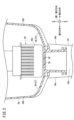
- FIG. 2 is a cross-sectional view of a blood reservoir according to an embodiment. 2 is a cross-sectional view taken along line II-II in FIG. 1.
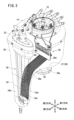
- FIG. FIG. 2 is a perspective perspective view showing the blood reservoir of FIG. 1 from diagonally above on the left side.
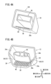
- FIG. 4A is a cut perspective view of a blood reservoir according to a comparative example
- FIG. 4B is a cut perspective view of a blood reservoir according to an embodiment.
- the blood storage tank 10 includes a venous reservoir that temporarily stores venous blood removed from a patient's vein, and intracardiac blood (suctioned blood) aspirated from the surgical field (external to the heart).
- This is an integrated blood storage tank that is integrated with a blood storage tank (cardiotomy reservoir) that temporarily stores blood.
- the blood reservoir 10 is, for example, incorporated into an extracorporeal circulation circuit used in cardiac surgery, and is used to filter and defoam venous blood or intracardiac blood and temporarily store the blood.
- the blood reservoir 10 includes a housing 12, a venous blood port 14, a suction blood port 16, and an outflow port 18.
- the housing 12 includes a main body 20 and a lid 22.
- the main body portion 20 has an internal space 12a that stores blood therein.
- the lid 22 covers the upper opening of the main body 20 .
- the venous blood port 14 and the suction blood port 16 are formed in the lid body 22.
- Venous blood port 14 introduces venous blood into interior space 12a.
- the suction blood port 16 introduces intracardiac blood into the internal space 12a.
- Outflow port 18 is located at bottom 25 of housing 12. The outflow port 18 allows blood to flow out from the internal space 12a of the blood reservoir 10.
- the housing 12 is formed of a transparent or translucent resin material, and allows the liquid level of blood stored in the internal space 12a to be visually recognized.
- the main body section 20 has a blood storage section 24 and a cardiotomy section 26.
- the cardiotomy portion 26 is a portion that bulges in the first direction and the second direction in FIG.
- the cardiotomy section 26 has a first filter section 28 therein that filters intracardiac blood.
- the first filter section 28 includes a sponge filter 28b disposed inside a funnel-shaped introduction section 28a and an outer filter 28c.
- the suction blood port 16 communicates with the inside of the sponge filter 28b.
- the first filter section 28 has a lead-out part 28d below the introduction part 28a. The lead-out portion 28d guides the blood that has passed through the sponge filter 28b toward the bottom portion 26a of the cardiotomy portion 26.
- the blood storage part 24 is a part that protrudes downward in an elongated manner from the cardiotomy part 26.
- the blood storage portion 24 has a flat shape that is narrow in dimensions in the first and second directions and wide in the third and fourth directions.
- a second filter section 30 that filters venous blood is arranged in the blood storage section 24 .
- the second filter section 30 includes an elliptical cylindrical grid-like filter frame 30a and an outer filter 30b supported by the filter frame 30a.
- the filter frame 30a and the outer filter 30b have an elliptical cylindrical shape having a long axis in a third direction perpendicular to the paper surface of FIG. 1 when viewed from above.
- the lower end of the filter frame 30a abuts against the bottom 25 of the blood storage section 24.
- the venous blood port 14 communicates with the inside of the outer filter 30b.
- the housing 12 has a connecting portion 34 that smoothly connects the bottom portion 26a of the cardiotomy portion 26 and the first side wall 24a of the blood storage portion 24 in the first direction.
- the connecting portion 34 has a flow path surface portion 36 and a flow guiding portion 37 .
- the flow path surface portion 36 has a surface parallel to the third direction and the fourth direction.
- the flow path surface portion 36 extends from below the lead-out portion 28d toward the first side wall 24a while increasing the downward inclination angle.
- the flow path surface portion 36 has a bent portion 36a whose inclination angle increases rapidly on the way from the cardiotomy portion 26 to the first side wall 24a.
- the bent portion 36a is located at the boundary between the cardiotomy portion 26 and the blood storage portion 24.
- the housing 12 has a plurality of ribs 40 on the flow path surface portion 36 that protrude toward the upper internal space 12a.
- the rib 40 extends downward in a direction parallel to the second direction and the vertical direction.
- the plurality of ribs 40 are arranged in the third and fourth directions at regular intervals.
- the plurality of ribs 40 are arranged parallel to each other.
- the flow guide portion 37 is a portion that guides blood to the flow path surface portion 36, and has an inclined surface 38 in this embodiment.
- the inclined surfaces 38 are arranged on the side portions of the flow path surface portion 36 on the third direction side and on the side portions of the flow path surface portion 36 on the fourth direction side.
- the inclined surface 38 slopes upward as it moves away from the channel surface portion 36.
- Such an inclined surface 38 serves to collect blood in the cardiotomy section 26 onto the flow path surface section 36 due to its inclination.
- the inclined surface 38 extends to the tip of the bent portion 36a and is connected to the second side wall 24b and the third side wall 24c of the blood storage portion 24.
- connection portion between the inclined surface 38 and the side walls 26b, 26c of the cardiotomy section 26 may have an R shape with a smooth curved surface when viewed from the front, as shown in FIG.
- the connecting portion between the inclined surface 38 and the side walls 26b, 26c may have a C-plane shape with an inclined planar connecting surface.
- the second side wall 24b of the blood storage section 24 is a side wall adjacent to the first side wall 24a in the third direction.
- the third side wall 24c is a side wall adjacent to the first side wall 24a in the fourth direction.
- the second side wall 24b and the third side wall 24c are inclined with respect to the third direction and the fourth direction.
- the blood reservoir 10 of this embodiment is configured as described above. This blood reservoir 10 functions as follows.
- Venous blood flows into the blood storage section 24 through the second filter section 30, and aspirated blood flows into the blood storage section 24 through the cardiotomy section 26.
- Blood is stored in the blood storage section 24, and a liquid surface of the blood is formed at a predetermined position.
- Blood flowing into the cardiotomy section 26 is collected on the flow path surface section 36 by the slope of the slope surface 38, and flows into the blood storage section 24 along the flow path surface section 36. Since a plurality of ribs 40 are formed on the flow path surface portion 36, the ribs 40 regulate the flow of blood. Furthermore, the fluid resistance of the plurality of ribs 40 suppresses the blood flow rate. Therefore, blood flowing along the ribs 40 flows into the blood storage section 24 without involving air bubbles.
- the inclined surface 38 adjacent to the flow path surface portion 36 extends beyond the bent portion 36a. Therefore, the housing 12 can efficiently guide blood to the plurality of ribs 40 even near the bent portion 36a where the downward inclination angle of the flow path surface portion 36 rapidly increases. Therefore, the inclined surface 38 can reliably prevent blood from flowing around the plurality of ribs 40 having large fluid resistance.
- the inclined surface 38 is not provided on the side of the flow path surface portion 36.
- blood flows along the portion where the plurality of ribs 40 are not provided. Fluid resistance is relatively small on the partial surface that does not have the ribs 40. Therefore, the flow velocity of the blood in the portion not having the ribs 40 increases, and the blood flows into the liquid surface of the blood storage portion 24 at a relatively high flow velocity and with turbulence. As a result, air is trapped at the liquid surface, increasing the frequency of bubble generation.
- the problems of the comparative example can be solved and the generation of bubbles can be suppressed.
- the blood reservoir 10 of this embodiment is not limited to the above example.
- the flow guide portion 37 may have an uneven structure that collects blood on the flow path surface portion 36. Further, the flow guide portion 37 may have a surface tension gradient that repels blood toward the flow path surface portion 36 .
- the blood reservoir 10 of this embodiment is summarized below.
- the blood storage tank 10 includes a cardiotomy section 26 into which aspirated blood flows, a blood storage section 24 that projects downwardly from the cardiotomy section and stores venous blood and the aspirated blood, a bottom section 26a of the cardiotomy section, and a connecting part 34 that connects to the bottom 25 of the blood storage part, the connecting part having a flow path surface part 36 that extends smoothly down from the bottom of the cardiotomy part to the bottom of the blood storage part. , a plurality of ribs 40 protruding inwardly from the flow path surface and extending parallel to each other downward toward the lower end of the blood storage portion at intervals in the horizontal direction, and formed on both sides of the flow path surface. , a flow guide portion 37 that guides the suctioned blood to the plurality of ribs.
- the plurality of ribs regulates the flow of the aspirated blood, and the fluid friction generated in the ribs suppresses the flow rate of the aspirated blood, thereby preventing the generation of bubbles due to air entrainment. Further, since the blood reservoir has the flow guide portion, it is possible to prevent the flow of the aspirated blood that bypasses the plurality of ribs and falls down rapidly, so that the generation of air bubbles can be more effectively prevented.
- the flow guide portion may have an inclined surface 38 that gradually slopes upward as it moves away from the flow path surface portion toward the side.
- This blood reservoir can guide aspirated blood to a plurality of ribs by utilizing the slope of the slope.
Landscapes
- Health & Medical Sciences (AREA)
- Heart & Thoracic Surgery (AREA)
- Vascular Medicine (AREA)
- Biomedical Technology (AREA)
- Engineering & Computer Science (AREA)
- Anesthesiology (AREA)
- Cardiology (AREA)
- Hematology (AREA)
- Life Sciences & Earth Sciences (AREA)
- Animal Behavior & Ethology (AREA)
- General Health & Medical Sciences (AREA)
- Public Health (AREA)
- Veterinary Medicine (AREA)
- External Artificial Organs (AREA)
Abstract
人工心肺装置等の体外循環回路に用いられる貯血槽であって、吸引血が流入するカーディオトミー部と、カーディオトミー部から下方に細長く突出し、静脈血及び吸引血を貯留する貯血部(24)と、カーディオトミー部の底部(26a)から、貯血部(24)のカーディオトミー部に隣接する第1側壁(24a)に向かって滑らかに下るように接続された接続部と、を備え、接続部は、貯血部(24)の長手方向と平行な面よりなる第1側壁(24a)に繋がる流路面部(36)と、貯血部(24)の下端に向けて下方に平行に延びる複数本のリブ(40)と、吸引血を複数本のリブ(40)に案内する導流部(37)と、を有することを特徴とする貯血槽。
Description
本発明は、人工心肺装置等の体外循環回路に用いられる貯血槽に関する。
心臓手術中の生命維持を目的に、一時的に心臓及び/又は肺の機能代行を行う体外循環回路が用いられる。この種の体外循環回路は、患者の静脈から脱血された静脈血の貯留と、術野に溢れた心内血(吸引血ともいう)の貯留と、を兼ね備えた貯血槽が用いられる(例えば、特許第4952232号公報)。このタイプの貯血槽は、心内血が流入する幅広なカーディオトミー部と、下方に向けて細長く突出して静脈血と心内血とを貯留する貯血部とを有する。
この特許第4952232号公報の貯血槽は、カーディオトミー部を通過した血液が、貯血部の液面に向かって勢いを増しながら流れ落ちる。そのため、流れ落ちた血液が液面に当たった際に、気泡が発生する可能性が高く、流出ポートから気泡が流出する可能性が高いという問題がある。
本発明は、上記した課題を解決することを目的とする。
以下の開示の一観点は、吸引血が流入するカーディオトミー部と、前記カーディオトミー部から下方に細長く突出し、静脈血及び前記吸引血を貯留する貯血部と、前記カーディオトミー部の底部と、前記貯血部の底部とを接続する接続部と、を備え、前記接続部は、前記カーディオトミー部の底部から前記貯血部の底部まで滑らかに下るように延在する流路面部を有し、前記流路面部から内方に突出し、水平方向に互いに間隔をあけて前記貯血部の下端に向けて下方に互いに平行に延びる複数本のリブと、前記流路面部の両側部に形成され、前記吸引血を前記複数本のリブに導く導流部と、を有する貯血槽にある。
上記観点の貯血槽によれば、複数本のリブが吸引血の流れを整えるとともに、リブに生じる流体摩擦で吸引血の流速を抑制することで空気の巻き込みによる気泡発生を防止する。さらに、貯血槽は、導流部を有することにより、複数のリブを迂回して勢いよく落下する吸引血の流れを阻止できるため、より効果的に気泡の発生を防止できる。
図1に示す本実施形態に係る貯血槽10は、患者の静脈から脱血した静脈血を一時的に貯留する静脈リザーバと、術野(心臓の外部)から吸引した心内血(吸引血)を一時的に貯留しておく貯血槽(カーディオトミーリザーバ)とが一体になった、一体型の貯血槽である。
貯血槽10は、例えば、心臓外科手術で用いられる体外循環回路に組み込まれて、静脈血や心内血を濾過及び消泡して、一時的に貯血するために用いられる。
貯血槽10は、ハウジング12と、静脈血ポート14と、吸引血ポート16と、流出ポート18とを備える。ハウジング12は、本体部20と、蓋体22とを有する。本体部20は、その内部に血液を貯血する内部空間12aを有する。蓋体22は、本体部20の上部の開口を覆う。静脈血ポート14及び吸引血ポート16は、蓋体22に形成されている。静脈血ポート14は、内部空間12aに静脈血を導入する。吸引血ポート16は、内部空間12aに心内血を導入する。流出ポート18は、ハウジング12の底部25に位置する。流出ポート18は、貯血槽10の内部空間12aから血液を流出させる。
ハウジング12は、透明又は半透明の樹脂材料によって形成され、内部空間12aに貯留された血液の液面を視認できる。本体部20は、貯血部24と、カーディオトミー部26とを有する。カーディオトミー部26は、図1の第1方向及び第2方向に膨出した部分である。カーディオトミー部26は、内部に心内血を濾過する第1フィルタ部28を有する。第1フィルタ部28は、漏斗状の導入部28aの内部に配置されたスポンジフィルタ28bと、外側フィルタ28cとを有する。吸引血ポート16は、スポンジフィルタ28bの内側に連通する。第1フィルタ部28は、導入部28aの下に導出部28dを有する。導出部28dは、スポンジフィルタ28bを通過した血液を、カーディオトミー部26の底部26aに向けて導く。
一方、貯血部24は、カーディオトミー部26よりも下方に細長く突出する部分である。貯血部24は、第1、第2方向の寸法が狭く、第3、第4方向に幅広に形成された扁平な形状を有する。貯血部24には、静脈血を濾過する第2フィルタ部30が配置される。第2フィルタ部30は、楕円筒状の格子状のフィルタフレーム30aと、フィルタフレーム30aに支持された外張フィルタ30bとを有する。フィルタフレーム30a及び外張フィルタ30bとは、上方から見て図1の紙面に垂直な第3方向に長軸を有する楕円筒状の形状を有する。フィルタフレーム30aの下端は、貯血部24の底部25に当接する。静脈血ポート14は、外張フィルタ30bの内側に連通する。
図2及び図3に示すように、ハウジング12は、カーディオトミー部26の底部26aと貯血部24の第1方向側の第1側壁24aとを滑らかに接続する接続部34を有する。接続部34は、流路面部36と、導流部37とを有する。流路面部36は、第3方向及び第4方向に平行な面を有する。流路面部36は導出部28dの下方から、第1側壁24aに向けて、下方への傾斜角を増大させつつ延在する。流路面部36は、カーディオトミー部26から第1側壁24aへ向かう途中で、傾斜角度が急増する屈曲部36aを有する。屈曲部36aは、カーディオトミー部26と貯血部24との境界に位置する。
ハウジング12は、流路面部36に、上方の内部空間12aに向けて突出する複数本のリブ40を有する。リブ40は、第2方向及び鉛直方向に平行な向きで、下方に向けて延在する。複数本のリブ40は、互いに一定の間隔をあけて、第3、第4方向に複数本配置されている。複数のリブ40は、互いに平行に配置される。
導流部37は、流路面部36に血液を導く部分であり、本実施形態では傾斜面38を有する。傾斜面38は、流路面部36の第3方向側の側部と、流路面部36の第4方向側の側部とにそれぞれ配置される。傾斜面38は、流路面部36から離れるにしたがって上方に向かうように傾斜する。このような傾斜面38は、傾斜によってカーディオトミー部26の血液を流路面部36に集める役割を果たす。傾斜面38は、屈曲部36aの先まで延びており、貯血部24の第2側壁24b及び第3側壁24cに繋がる。なお、傾斜面38とカーディオトミー部26の側壁26b、26cとの接続部分は、図2に示すように、正面視で滑らかな湾曲面を有するR形状を呈してもよい。あるいは、傾斜面38と側壁26b、26cとの接続部分は、傾斜した平面状の接続面を有するC面形状を呈していてもよい。
貯血部24の第2側壁24bは、第1側壁24aの第3方向側に隣接する側壁である。第3側壁24cは、第1側壁24aの第4方向側に隣接する側壁である。第2側壁24b及び第3側壁24cは、第3方向及び第4方向に対して傾斜する。
本実施形態の貯血槽10は以上のように構成される。この貯血槽10は、以下のように作用する。
静脈血は、第2フィルタ部30を通じて貯血部24に流入し、吸引血はカーディオトミー部26を介して貯血部24に流入する。貯血部24には、血液が貯留され、所定位置に血液の液面が形成される。
カーディオトミー部26に流入した血液は、傾斜面38の傾斜によって、流路面部36に集められ、流路面部36に沿って貯血部24に流入する。流路面部36には、複数本のリブ40が形成されているため、リブ40によって血液の流れが整えられる。また、複数本のリブ40の流体的な抵抗により、血液の流速が抑制される。そのため、リブ40に沿って流れる血液は、気泡を巻き込むことなく貯血部24に流れ込む。
図4Bに示すように、本実施形態のハウジング12は、流路面部36に隣接する傾斜面38が屈曲部36aを超えて延在する。このため、ハウジング12は、流路面部36の下方への傾斜角が急増する屈曲部36a付近においても、血液を効率的に複数本のリブ40に導くことができる。このため、傾斜面38は、流体抵抗の大きな複数本のリブ40を迂回する血液の流れの発生を確実に防止できる。
これに対し、図4Aの比較例に係るハウジング120は、流路面部36の側部に傾斜面38が設けられていない。この比較例のハウジング120では、複数本のリブ40が設けられていない部分に沿った血液の流れが生じる。リブ40を有さない部分面では、流体抵抗が比較的小さい。そのため、リブ40を有さない部分の血液の流速が増大してしまい、血液が比較的大きな流速で乱流を伴いながら貯血部24の液面に流入する。その結果、液面で空気の巻き込みを生じ、気泡の発生頻度が増大してしまう。
図4Bに示す本実施形態の貯血槽10によれば、比較例の問題を解消することができ、気泡の発生を抑制できる。
(変形例)
本実施形態の貯血槽10は、上記の例に限定されない。導流部37は、傾斜面38以外にも、血液を流路面部36に集める凹凸構造で構成されてもよい。また、導流部37は、血液を流路面部36に向けて弾く表面張力勾配を有してもよい。
本実施形態の貯血槽10は、上記の例に限定されない。導流部37は、傾斜面38以外にも、血液を流路面部36に集める凹凸構造で構成されてもよい。また、導流部37は、血液を流路面部36に向けて弾く表面張力勾配を有してもよい。
本実施形態の貯血槽10は、以下にまとめられる。
貯血槽10は、吸引血が流入するカーディオトミー部26と、前記カーディオトミー部から下方に細長く突出し、静脈血及び前記吸引血を貯留する貯血部24と、前記カーディオトミー部の底部26aと、前記貯血部の底部25とを接続する接続部34と、を備え、前記接続部は、前記カーディオトミー部の底部から前記貯血部の底部まで滑らかに下るように延在する流路面部36を有し、前記流路面部から内方に突出し、水平方向に互いに間隔をあけて前記貯血部の下端に向けて下方に互いに平行に延びる複数本のリブ40と、前記流路面部の両側部に形成され、前記吸引血を前記複数本のリブに導く導流部37と、を有する。
上記観点の貯血槽によれば、複数本のリブが吸引血の流れを整えるとともに、リブに生じる流体摩擦で吸引血の流速を抑制することで空気の巻き込みによる気泡発生を防止する。さらに、貯血槽は、導流部を有することにより、複数のリブを迂回して勢いよく落下する吸引血の流れを阻止できるため、より効果的に気泡の発生を防止できる。
上記の貯血槽10において、前記導流部は、前記流路面部から側部に離れるにしたがって徐々に上方に向けて傾斜する傾斜面38を有してもよい。この貯血槽は、傾斜面の傾斜を利用して吸引血を複数のリブに導くことができる。
なお、本発明は、上記した実施形態に限らず、本発明の要旨を逸脱することなく、種々の構成を採り得る。
Claims (2)
- 吸引血が流入するカーディオトミー部と、
前記カーディオトミー部から下方に細長く突出し、静脈血及び前記吸引血を貯留する貯血部と、
前記カーディオトミー部の底部と、前記貯血部の底部とを接続する接続部と、を備え、
前記接続部は、
前記カーディオトミー部の底部から前記貯血部の底部まで滑らかに下るように延在する流路面部を有し、
前記流路面部から内方に突出し、水平方向に互いに間隔をあけて前記貯血部の下端に向けて下方に互いに平行に延びる複数本のリブと、
前記流路面部の両側部に形成され、前記吸引血を前記複数本のリブに導く導流部と、を有する貯血槽。 - 請求項1記載の貯血槽であって、前記導流部は、前記流路面部から側部に離れるにしたがって徐々に上方に向けて傾斜する傾斜面を有する、貯血槽。
Applications Claiming Priority (2)
| Application Number | Priority Date | Filing Date | Title |
|---|---|---|---|
| JP2022-049190 | 2022-03-25 | ||
| JP2022049190A JP2025073126A (ja) | 2022-03-25 | 2022-03-25 | 貯血槽 |
Publications (1)
| Publication Number | Publication Date |
|---|---|
| WO2023181798A1 true WO2023181798A1 (ja) | 2023-09-28 |
Family
ID=88100552
Family Applications (1)
| Application Number | Title | Priority Date | Filing Date |
|---|---|---|---|
| PCT/JP2023/007194 Ceased WO2023181798A1 (ja) | 2022-03-25 | 2023-02-28 | 貯血槽 |
Country Status (2)
| Country | Link |
|---|---|
| JP (1) | JP2025073126A (ja) |
| WO (1) | WO2023181798A1 (ja) |
Citations (4)
| Publication number | Priority date | Publication date | Assignee | Title |
|---|---|---|---|---|
| JPH04336076A (ja) * | 1991-05-13 | 1992-11-24 | Terumo Corp | 除泡装置および貯血槽 |
| JPH06343694A (ja) * | 1993-06-10 | 1994-12-20 | Terumo Corp | 貯血槽 |
| JPH09285538A (ja) * | 1996-04-19 | 1997-11-04 | Senko Ika Kogyo Kk | 液体リザーバ |
| JP2021069733A (ja) * | 2019-10-31 | 2021-05-06 | 株式会社ジェイ・エム・エス | 貯血槽 |
-
2022
- 2022-03-25 JP JP2022049190A patent/JP2025073126A/ja active Pending
-
2023
- 2023-02-28 WO PCT/JP2023/007194 patent/WO2023181798A1/ja not_active Ceased
Patent Citations (4)
| Publication number | Priority date | Publication date | Assignee | Title |
|---|---|---|---|---|
| JPH04336076A (ja) * | 1991-05-13 | 1992-11-24 | Terumo Corp | 除泡装置および貯血槽 |
| JPH06343694A (ja) * | 1993-06-10 | 1994-12-20 | Terumo Corp | 貯血槽 |
| JPH09285538A (ja) * | 1996-04-19 | 1997-11-04 | Senko Ika Kogyo Kk | 液体リザーバ |
| JP2021069733A (ja) * | 2019-10-31 | 2021-05-06 | 株式会社ジェイ・エム・エス | 貯血槽 |
Also Published As
| Publication number | Publication date |
|---|---|
| JP2025073126A (ja) | 2025-05-13 |
Similar Documents
| Publication | Publication Date | Title |
|---|---|---|
| EP1210956B1 (en) | Blood reservoir | |
| JPS6312632B2 (ja) | ||
| US20110098626A1 (en) | Blood reservoir | |
| JPH0999066A (ja) | フィルタを内部に備えた心臓切開術用血液リザーバ | |
| JP5046063B2 (ja) | 貯血槽 | |
| JP5293067B2 (ja) | 貯血槽 | |
| JP2025073126A (ja) | 貯血槽 | |
| JP2021007419A (ja) | 貯血槽 | |
| US11357898B1 (en) | Hybrid venous reservoir | |
| CN101277729B (zh) | 封闭型储血槽及使用该储血槽的体外血液循环装置 | |
| JP7459480B2 (ja) | 貯血槽 | |
| JP2010088736A (ja) | フィルタ部材、貯血槽 | |
| CN115501407B (zh) | 膜式氧合器贮血罐 | |
| JP7827512B2 (ja) | 貯血槽 | |
| JP4485707B2 (ja) | 貯血槽 | |
| JP7447419B2 (ja) | 貯血槽 | |
| JPS6145770A (ja) | 貯血槽 | |
| JP6654707B2 (ja) | 血液処理組立体を有する血液リザーバ | |
| JP4952232B2 (ja) | 貯血槽 | |
| JP2017225534A (ja) | 貯血槽 | |
| WO2022158465A1 (ja) | 貯血槽 | |
| CN221787572U (zh) | 一种双向除气的血液腔室 | |
| JP3220237B2 (ja) | 遠心ポンプ付き貯血槽 | |
| WO2022158464A1 (ja) | 貯血槽 | |
| JPWO2009028396A1 (ja) | 貯血槽 |
Legal Events
| Date | Code | Title | Description |
|---|---|---|---|
| 121 | Ep: the epo has been informed by wipo that ep was designated in this application |
Ref document number: 23774397 Country of ref document: EP Kind code of ref document: A1 |
|
| NENP | Non-entry into the national phase |
Ref country code: DE |
|
| 122 | Ep: pct application non-entry in european phase |
Ref document number: 23774397 Country of ref document: EP Kind code of ref document: A1 |
|
| NENP | Non-entry into the national phase |
Ref country code: JP |