WO2023181741A1 - センサモジュール、マウスピース型デバイス及びシステム - Google Patents
センサモジュール、マウスピース型デバイス及びシステム Download PDFInfo
- Publication number
- WO2023181741A1 WO2023181741A1 PCT/JP2023/005759 JP2023005759W WO2023181741A1 WO 2023181741 A1 WO2023181741 A1 WO 2023181741A1 JP 2023005759 W JP2023005759 W JP 2023005759W WO 2023181741 A1 WO2023181741 A1 WO 2023181741A1
- Authority
- WO
- WIPO (PCT)
- Prior art keywords
- sensor
- storage chamber
- flow path
- enzyme
- mouthpiece
- Prior art date
- Legal status (The legal status is an assumption and is not a legal conclusion. Google has not performed a legal analysis and makes no representation as to the accuracy of the status listed.)
- Ceased
Links
Images








Classifications
-
- A—HUMAN NECESSITIES
- A61—MEDICAL OR VETERINARY SCIENCE; HYGIENE
- A61B—DIAGNOSIS; SURGERY; IDENTIFICATION
- A61B5/00—Measuring for diagnostic purposes; Identification of persons
-
- G—PHYSICS
- G01—MEASURING; TESTING
- G01N—INVESTIGATING OR ANALYSING MATERIALS BY DETERMINING THEIR CHEMICAL OR PHYSICAL PROPERTIES
- G01N27/00—Investigating or analysing materials by the use of electric, electrochemical, or magnetic means
- G01N27/26—Investigating or analysing materials by the use of electric, electrochemical, or magnetic means by investigating electrochemical variables; by using electrolysis or electrophoresis
- G01N27/416—Systems
Definitions
- the present disclosure relates to sensor modules, mouthpiece-type devices, and systems.
- VR Virtual Reality
- the market size of VR is expected to expand to the same extent as mobile in the next few years, and it is expected that it will become widespread as a general technology in the world.
- some users may feel "sickness" similar to motion sickness when continuing to play VR. Therefore, for the spread of VR, it is desired to develop a technology that detects signs of motion sickness and prevents or suppresses motion sickness. In developing this technology, detection of signs of intoxication is particularly important.
- Patent Document 1 discloses a device that detects the concentration of amylase (enzyme) in saliva in the oral cavity by utilizing the fact that amylase, one of the enzymes in saliva, is a tracer of pleasure and discomfort during symptoms of intoxication. is proposed. Specifically, it includes an electron-generating capsule that generates electrons by reacting with an enzyme, and a concave structure that holds the electron-generating capsule, and measures the concentration of the enzyme by measuring the current caused by the generated electrons. A sensor module has been proposed.
- the sensor module described in Patent Document 1 further includes a movable shielding plate that shields and opens the opening of the concave structure, and allows the shielding plate to open and close the opening of the concave structure, thereby preventing the introduction of liquid into the opening. It's in control.
- the sensor module described in Patent Document 1 when detecting the concentration of enzymes in saliva, the sensor module is mounted on the side wall surface of the mouthpiece, and the sensor module is mounted on the side wall surface of the mouthpiece, and the Saliva is adapted to be introduced into the recessed structure of the sensor module.
- the sensor module needs to be installed at a certain distance from the orifice. Therefore, even if the opening of the concave structure is opened, saliva may not flow into the opening of the concave structure, and the enzyme concentration in saliva may not be measured appropriately.
- An object of the present disclosure is to provide a sensor module, a mouthpiece type device, and a system that can sensitively measure the concentration of an enzyme in a liquid to be detected.
- the sensor module of the present disclosure includes (a) a flow channel whose one open end is open toward the outside, and (b) a storage chamber that acquires and stores a liquid to be detected from the outside via the flow channel. , (c) a movable wall that forms the wall of the storage chamber and is deformable in the direction in which the volume of the storage chamber changes; and (d) a wall surface facing the movable wall of the storage chamber or opposite to the flow path side of the storage chamber. and an enzyme sensor that is placed on the side wall and measures the concentration of enzyme in the liquid.
- the mouthpiece-type device of the present disclosure includes (a) a channel in which one open end is open toward the outside, and (b) a storage chamber that acquires and stores a liquid to be detected from the outside through the channel. , (c) a movable wall that forms the wall of the storage chamber and is deformable in the direction in which the volume of the storage chamber changes; (d) and a wall side facing the movable wall of the storage chamber or opposite to the flow path side of the storage chamber.
- a sensor module that is disposed on a side wall and includes an enzyme sensor that measures the concentration of an enzyme in a liquid; and (e) a mouthpiece in which the sensor module is mounted.
- the system of the present disclosure includes (a) a flow channel whose one open end is open toward the outside, (b) a storage chamber that acquires and stores a liquid to be detected from the outside via the flow channel, (c) ) a movable wall that forms the wall of the storage chamber and is deformable in the direction in which the volume of the storage chamber changes; (d) a wall side facing the movable wall of the storage chamber or a wall side opposite to the channel side of the storage chamber; (e) a sensor module including an enzyme sensor arranged in a liquid to measure the concentration of enzyme in a liquid and a transmitter that transmits a signal output from the enzyme sensor; (f) a mouthpiece in which the sensor module is mounted; (g) an external device that receives a signal transmitted from the mouthpiece type device and starts driving a predetermined function using the received signal as a trigger.
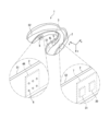
- FIG. 1 is a diagram showing the overall configuration of a mouthpiece type device according to a first embodiment.
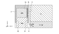
- FIG. 2 is a diagram showing a cross-sectional configuration of the mouthpiece type device when cut along a plane parallel to the yz plane of FIG. 1.
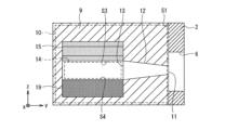
- FIG. 2 is a diagram showing the overall configuration of a sensor module. It is a figure showing the cross-sectional structure of the mouthpiece type device concerning a modification.
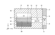
- 4 is a diagram illustrating a cross-sectional configuration of the sensor unit when cut along a plane parallel to the yz plane of FIG. 3.
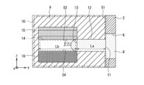
- FIG. It is a figure which shows the cross-sectional structure of a movable wall when it is in a curved state.
- FIG. 1 is a diagram showing the overall configuration of an enzyme sensor. It is a figure showing the whole structure of an enzyme sensor concerning a modification. It is a figure showing the cross-sectional structure of the sensor unit when it is in a flat state.
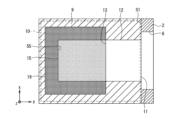
- FIG. 17 is a diagram showing a cross-sectional configuration of the sensor unit when cut along a plane parallel to the xy plane of FIG. 16.
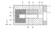
- FIG. It is a figure showing the cross-sectional structure of the sensor unit concerning modification (2).
- FIG. 3 is a diagram showing a cross-sectional configuration of the sensor unit in a curved state. It is a figure showing the whole structure of a sensor module concerning modification (3). It is a figure showing the cross-sectional structure of the sensor unit concerning modification (4).
- FIG. 2 is a diagram showing a schematic configuration of a system according to a second embodiment.
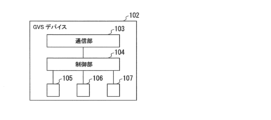
- FIG. 3 is a diagram showing the internal configuration of a GVS device.
- FIG. 1 is a diagram showing the overall configuration of a mouthpiece type device 1 according to the first embodiment.
- the mouthpiece type device 1 targets a user who is playing VR, and is attached to the user to continuously measure the concentration of enzymes in saliva and time-series monitor the signs of motion sickness during continuous VR play. It is a device for Examples of enzymes include amylase.
- a mouthpiece type device 1 includes a mouthpiece 2.
- the mouthpiece 2 is a lower jaw mouthpiece that is detachably attached to the lower jaw of a person to be measured.
- FIG. 2 is a diagram showing a cross-sectional configuration of the mouthpiece type device 1 when cut along a plane parallel to the yz plane of FIG.
- the mouthpiece 2 is formed into a substantially U-shape in plan view in accordance with the lower jaw row of teeth of the person to be measured so as to cover the crowns of all teeth and the upper part of the gums of the lower jaw row of teeth.
- a sports mouthpiece can be adopted.
- An example of the thickness of the mouthpiece 2 is, for example, about 3 mm.
- a pressure sensor 3 is provided on the tongue-side or palate-side wall surface (hereinafter also referred to as "first wall surface S1") of the surface of the mouthpiece 2 that contacts the tooth crown (hereinafter also referred to as “inner surface”).
- sensor modules 4L and 4R, and a logic unit 5 (“control unit” in a broad sense) are arranged.
- a plurality of orifices 6 are formed at the positions of the mouthpiece 2 where the sensor modules 4L, 4R are arranged.
- FIG. 1 illustrates a case where six cylindrical through holes penetrating the first wall surface S1 of the mouthpiece 2 are formed as the orifice 6 at each position where the sensor modules 4L and 4R are arranged.
- the saliva 8 in the oral cavity enters the orifice 6 and the saliva 8 in the orifice 6 is formed. is formed at a position facing one open end 11 of the flow path 12 so as to enter into the flow path 12 shown in FIG.
- a power source/RF section 7 is disposed on the cheek-side or lip-side wall (hereinafter also referred to as "second wall surface S2") of the inner surface of the mouthpiece 2.
- the mouthpiece 2 may have a configuration in which a function for measuring the external environment, such as a GPS receiver or an acceleration sensor, is implemented.
- the pressure sensor 3 is disposed on the first wall surface S1 of the mouthpiece 2 at a portion that is in contact with both the back side of the front teeth and the top surface of the front teeth.
- the pressure sensor 3 detects pressure applied to a portion of the mouthpiece 2 located behind the front teeth or a portion located on the top surface of the front teeth. Thereby, when the person to be measured presses the pressure sensor 3 with his tongue or bites the pressure sensor 3, a signal corresponding to the pressure is output from the pressure sensor 3. The output signal is input to the logic section 5.
- the sensor modules 4L and 4R are disposed on the first wall surface S1 of the mouthpiece 2 at the portions that contact the back sides of the left and right molars (hereinafter also referred to as “molar contact portions").
- the sensor modules 4L and 4R measure the concentration of an enzyme (amylase) in the saliva 8 (in a broad sense, "liquid to be measured") of a person to be measured. Note that since the sensor modules 4L and 4R have the same structure although the left and right sides are reversed, only the structure of the sensor module 4L will be described below. As shown in FIG. 3, the sensor module 4L includes a flat case 9 that accommodates each component of the sensor module 4L.
- the thickness direction of the flat sensor module 4L thickness direction of the flat sensor module 4L (thickness direction of the flat plate) will be referred to as the "y direction", and the direction along one side of the flat sensor module 4L (one side of the flat plate) will be referred to as the "y direction”.
- the direction along the other side is called the "z direction”.
- the xz plane is along the molar contact area of the first wall surface S1
- the z direction is parallel to the vertical direction (direction from the bottom to the top)
- the y direction is parallel to the width direction (from the buccal or labial side to the tongue).
- the first wall surface S1 is disposed at the back tooth contacting portion of the first wall surface S1 so as to be parallel to the side or the direction toward the palate side.
- the housing 9 (sensor module 4L) is configured to be detachable from the mouthpiece 2.
- FIG. 2 it is possible to adopt a configuration in which a recess 2a into which the housing 9 can be fitted is formed in the molar contact portion of the first wall surface S1, and the housing 9 is fitted and fixed into the recess 2a. .
- the mouthpiece 2 can be reused by replacing the sensor module 4L.
- the first embodiment shows an example in which the sensor module 4L is mounted on the side wall surface (first wall surface S1) of the mouthpiece 2, other configurations may also be adopted.
- it may be configured to be mounted within the side wall of the mouthpiece 2.
- An example of the dimensions of the housing 9 is a configuration in which the length in the z direction is 10 mm, the length in the x direction is 10 mm, and the length in the y direction is 2 mm.
- the size in side view can be made to be about the size of one molar tooth.
- the length in the y direction can be mounted in a sports mouthpiece (a relatively thick mouthpiece).
- resin can be used as the material for the housing 9, for example.
- a plurality of sensor units 10 are arranged in an array.
- six sensor units 10 are arranged in an array with two rows in the z direction (vertical direction in FIG. 3) and three rows in the x direction (direction from the front side to the back side in FIG. 3). is exemplified.
- the sensor unit 10 has one open end 11 that is open toward the outside on the y-direction side (right side in FIG. 5) of the sensor module 4L. It has a cylindrical flow path 12 extending to the opposite side. Thereby, when the sensor module 4L is mounted on the mouthpiece 2, one opening end 11 of the flow path 12 is configured to open toward the space within the orifice 6 of the first wall surface S1.
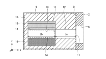
- FIG. 5 is a diagram showing a cross-sectional configuration of the sensor unit 10 when cut along a plane parallel to the yz plane of FIG. Further, the other open end 13 of the flow path 12 is opened toward the inside of a storage chamber 14 formed within the sensor unit 10.
- An example of the diameter of the flow path 12 is, for example, about 0.1 mm.
- the sensor unit 10 includes a storage chamber 14 in which the other open end 13 of the flow path 12 is opened toward the inside.
- the storage chamber 14 becomes a semi-cylindrical space extending along the y direction (that is, the same direction as the flow path 12) when the movable wall 15 is in a curved state as described later.
- the saliva 8 in the orifice 6 enters the flow path 12, and the entered saliva 8 can flow through the flow path 12, allowing the saliva to enter the storage chamber 14 from the outside via the flow path 12. It is now possible to acquire and accommodate 8.
- the heights of the storage chamber 14 and the flow path 12 on the z-direction side and the opposite side are the same.
- the heights of the storage chamber 14 and the flow path 12 on the z-direction side are also the same.
- the length in the x direction is 1 mm
- the length in the y direction is 1 mm
- the length in the z direction is 0.1 mm.
- a wall surface on the z-direction side (upper side in FIG. 5) of the storage chamber 14 is formed of a movable wall 15 that can be deformed in a direction in which the volume of the storage chamber 14 changes.
- the movable wall 15 includes a pair of soft electrodes 16 and 17 and a ferromagnetic material 18 sandwiched between the pair of soft electrodes 16 and 17, as shown in FIGS. 6 and 7.
- the center part of the movable wall 15 in the x direction moves in the z direction (upward in FIG. 5).
- a semi-cylindrical shape hereinafter also referred to as a "curved state"
- a voltage between the pair of soft electrodes 16 and 17 the inside of the ferromagnetic material 18 is polarized and Maxwell stress is generated, so that the center portion of the movable wall 15 in the x direction protrudes in the z direction.
- the movable wall 15 curves.
- the storage chamber 14 becomes a semi-cylindrical space, and the volume of the storage chamber 14 becomes maximum.
- the ferromagnetic material 18 for example, a conductive polymer containing a ferromagnetic material can be used.
- the pair of soft electrodes 16 and 17, for example carbon black electrodes can be used.
- a piezo element using a lead-free ferromagnetic material can also be used.
- a ferromagnetic material for example, an alloy containing bismuth (Bi) can be used.
- a shape memory alloy can also be used.
- the movable wall 15 when the application of voltage between the pair of soft electrodes 16 and 17 is stopped, the movable wall 15 is in a state in which it is deformed into a flat plate shape (hereinafter referred to as “ (also called “flat plate state”).
- the surface opposite to the z-direction side of the movable wall 15 (the lower surface in FIG. 6; hereinafter also referred to as "lower surface S3") and the storage chamber
- the z-direction side of the enzyme sensor 14 and the opposite wall surface in FIG.
- the lower wall surface hereinafter also referred to as "bottom surface S4"
- bottom surface S4 the opening of the concave structure 22 of the enzyme sensor 19 shown in FIG.
- This example shows the case of covering. That is, when the movable wall 15 is deformed in a direction in which the volume of the storage chamber 14 becomes smaller, the movable wall 15 contacts the enzyme sensor 19 and releases the electron generating capsule 24 (in a broad sense) arranged in the concave structure 22. It is configured to cover the "reaction section" (see FIG. 8). As a result, the volume of the storage chamber 14 becomes zero, and the volume of the storage chamber 14 becomes the minimum.
- the enzyme sensor 19 since the electron generating capsule 24 (reaction part) of the enzyme sensor 19 is covered with the movable wall 15 and does not come into contact with the saliva 8, the enzyme sensor 19 does not need to start measuring the concentration of the enzyme (amylase).
- the thickness of the movable wall 15 in the z direction is such that when the movable wall 15 is in a flat state, the side surface of the movable wall 15 closes the open end (the other open end 13) of the flow path 12 on the accommodation chamber 14 side.
- the diameter of the flow path 12 was set to be greater than the diameter of the flow path 12 so that the diameter of the flow path 12 could be increased.
- an enzyme sensor 19 is arranged on the wall surface (bottom surface S4) side (lower side in FIG. 5) facing the movable wall 15 of the storage chamber 14.
- the enzyme sensor 19 forms the bottom surface S4 of the storage chamber 14.
- the enzyme sensor 19 measures the concentration of enzyme (amylase) in the saliva 8 contained in the storage chamber 14 .
- the enzyme sensor 19 includes a pair of electrodes 20, 21, an electron transfer layer 23 having a concave structure 22, and an electron transfer layer 23 having a concave structure 22, which is sandwiched between the pair of electrodes 20, 21. and an electron generating capsule 24 held inside.
- the amount of enzyme (amylase) can be measured by measuring the current generated by the electrons generated in the electron generating capsule 24.
- the pair of electrodes 20 and 21 for example, an Ag electrode or a C electrode can be used.
- the electron transport layer 23 for example, a layer containing a gel-like mediator can be adopted.
- a layer containing a gelled potassium ferricyanide solution (electrolyte) may be mentioned.
- the electron-generating capsule 24 for example, a spherical starch ball having a spherical center portion 25 containing glucose oxidase, maltase, and PMEH wrapped in a thin starch film 26 can be adopted.
- the electron-generating capsule 24 (starch ball) and the gel-like mediator constitute a reaction section of the enzyme sensor 19. Thereby, the enzyme in the saliva 8 generates electrons from the positive electrode side of the pair of electrodes 20 and 21 through an oxidation/reduction reaction starting from the reaction with starch.
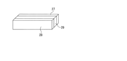
- an enzyme sensor including a pair of electrodes 27 and 28 and an electron generation layer 29 sandwiched between the pair of electrodes 27 and 28 can also be used.
- the amount of enzyme (amylase) can be measured by measuring the current due to electrons generated in the electron generation layer 29.
- the electron generation layer 29 for example, a layer containing starch, PQQ glucose dehydrogenase, and a mediator can be adopted.
- the movable wall 15 Let be a flat plate. Then, the other open end 13 of the flow path 12 is closed with the side surface of the movable wall 15, and the bottom surface S4 of the storage chamber 14 is covered with the lower surface S3 of the movable wall 15. Thereby, the saliva 8 does not enter the storage chamber 14, and the enzyme sensor 19 does not come into contact with the saliva 8.
- a voltage is applied between the pair of soft electrodes 16 and 17 to bend the movable wall 15 as shown in FIGS. 6 and 11.
- the movable wall 15 is in a curved state, the other open end 13 of the flow path 12 that was blocked by the side surface of the movable wall 15 is opened, and the storage chamber that was covered by the lower surface S3 of the movable wall 15 is opened. 14 bottom surface S4 is exposed.
- the volume of the storage chamber 14 increases, and a negative pressure is generated within the storage chamber 14 due to the increase in volume.
- the saliva 8 in the orifice 6 is drawn into the flow path 12 by the negative pressure generated in the storage chamber 14, and the drawn saliva 8 is stored in the storage chamber 14 via the flow path 12. Then, when the saliva 8 is accommodated in the accommodation chamber 14, the concentration of enzyme (amylase) in the accommodated saliva 8 is measured by the enzyme sensor 19. At this time, since a negative pressure is generated in the storage chamber 14, it is also possible to suppress the material of the electron-generating capsule 24 (reaction part) of the enzyme sensor 19 from seeping into the oral cavity.
- the length La of the flow path 12 in the direction in which the flow path 12 extends is preferably shorter than the length Lb of the storage chamber 14 (La ⁇ Lb).
- the saliva 8 can be contained in the storage chamber 14 instantaneously (for example, in 10 ⁇ 6 seconds), and the Enzyme (amylase) concentration measurement can be started instantly.
- the saliva 8 can be instantly accommodated in the accommodation chamber 14 due to the negative pressure caused by the increase in the volume of the accommodation chamber 14, as shown in the simulation results of the liquid level movement, as shown in FIGS. 12 and 13. be understood. That is, as shown in FIG.
- the moving speed v(t) of the saliva 8 at the elapsed time t after the movable wall 15 is deformed into the shape in which the volume of the storage chamber 14 is maximized is calculated by the following formula (2). It is expressed as Here, V0 is the volume of air in the flow path 12 when the movable wall 15 is in a flat state, and V(0) is the volume of the storage chamber 14 when the movable wall 15 is in a curved state. Then, a simulation of the liquid level movement was performed according to the above equation (2), and the simulation results shown in FIGS. 12 and 13 were obtained.
- the vertical axis represents the moving distance of the saliva 8
- the horizontal axis represents the elapsed time t after the movable wall 15 changes from the flat state to the curved state.
- FIG. 12 it can be seen that when La ⁇ Lb, the saliva 8 instantly reaches a position 0.9 mm from the entrance of the storage chamber 14 (the other open end 13).
- the power supply/RF section 7 includes a power supply 30 and a transmitter 31.
- the power supply 30 is a power supply that supplies power to the logic section 5 and the transmitter 31.
- the power source 30 for example, a lithium ion battery that can output a voltage of about 10V can be used.
- the transmitter 31 is controlled by the logic unit 5 and transmits a signal to an external device by wireless communication or wired communication.
- the wireless communication communication based on a wireless communication standard such as Bluetooth (registered trademark) can be adopted, for example.
- the logic unit 5 acquires the signal output from the pressure sensor 3, drives the movable wall 15, acquires the signal output from the enzyme sensor 19, and transmits the signal to an external device via the transmitter 31.
- the logic section 5 for example, an integrated circuit including a transistor can be used.
- the logic unit 5 starts the sensor modules 4L and 4R (step S101).
- the logic unit 5 selects one sensor unit 10 (hereinafter also referred to as "first sensor unit 10") among the six sensor units 10 of the sensor module 4L.
- step S102 Application of a voltage between the pair of soft electrodes 16 and 17 of the movable wall 15 (step S102) is started. That is, the transistor constituting the logic section 5 continuously applies a voltage (for example, 2V) for one minute to transform the movable wall 15 into a curved state. By applying the voltage, the logic unit 5 deforms the movable wall 15 into a curved state and increases the volume of the storage chamber 14 (step S103). As a result, a negative pressure is generated within the storage chamber 14, and saliva 8 within the orifice 6 is drawn into the storage chamber 14 via the flow path 12.
- a voltage for example, 2V
- Step S104 the reaction between the saliva 8 and the electron generating capsule 24 (reaction part) is started, and the measurement of the concentration of the enzyme (amylase) in the saliva 8 (amylase activity) is started.
- the logic unit 5 accumulates the signal output from the enzyme sensor 19 of the first sensor unit 10 (an electric signal caused by electrons generated by the reaction between the saliva 8 and the electron-generating capsule 24) for one minute, and stores the accumulated 1 The minute signal is transmitted to the external device via the transmitter 31 (step S105). Subsequently, the logic section 5 stops applying the voltage between the pair of soft electrodes 16 and 17 (movable wall 15) of the first sensor unit 10, as shown at time t2 in FIG. 15 (step S106). , the control target is switched from the first sensor unit 10 to the next sensor unit 10 (i-th sensor unit, where i is any one of 2 to 6) (step S107), and the flow of steps S102 to S106 is repeated.
- the transistor constituting the logic section 5 applies a voltage of 2V to each of the movable walls 15 of the plurality of sensor units 10 for one minute at a time, as shown at time t3 in FIG. Measure the concentration of (amylase).
- the logic unit 5 causes one movable wall 15 of the movable walls 15 included in the plurality of sensor units 10 to perform increase/decrease control to increase and decrease the volume of the storage chamber 14, and also controls the volume of the storage chamber 14 for a predetermined period of time ( It can also be said that the movable wall 15 to which the increase/decrease control is performed is switched every time one minute (1 minute) elapses.
- the concentration of the enzyme (amylase) in the saliva 8 in the oral cavity can be continuously measured by sequentially using the six sensor units 10 of the sensor module 4L.
- the logic section 5 causes each of the movable walls 15 of the plurality of sensor units 10 forming the sensor modules 4L and 4R to sequentially perform increase/decrease control.
- the logic section 5 causes each of the movable walls 15 of the plurality of sensor units 10 forming the sensor modules 4L and 4R to sequentially perform increase/decrease control.
- the sensor unit 10 to be controlled (that is, the sensor unit 10 that measures the enzyme concentration) is configured to be sequentially switched from the back tooth side to the front tooth side.
- saliva 8 is secreted from the sublingual gland in the oral cavity. Therefore, in the initial stage of concentration measurement, the concentration of the enzyme (amylase) in saliva 8 can be measured with high sensitivity by using the sensor unit 10 on the molar side near the sublingual gland. Furthermore, saliva 8 secreted from the sublingual gland spreads into the oral cavity over time. Therefore, in the middle and late stages of concentration measurement, even if the sensor unit 10 on the anterior tooth side far from the sublingual gland is used, the sensitivity of measuring the concentration of the enzyme (amylase) in saliva 8 will not decrease. It's over.
- a movable shielding plate that shields and opens the concave structure 22 of the enzyme sensor 19 is provided, and the shielding plate opens and closes the opening of the concave structure 22 to control the introduction of saliva 8 into the opening.
- the sensor modules 4L and 4R must be installed at a certain distance from the orifice 6 in consideration of the movable range of the shielding plate. Therefore, even if the opening of the concave structure 22 is opened, the saliva 8 may not flow into the opening of the concave structure 22, and the concentration of amylase (enzyme) in the saliva 8 may not be measured appropriately.
- the sensor modules 4L, 4R and the mouthpiece type device 1 there is a flow path 12 in which one opening end 11 is open toward the outside, and a flow path 12 that is connected to the outside through the flow path 12. and a storage chamber 14 that accommodates saliva 8 (liquid to be detected).
- the enzyme sensor 19 is arranged on the wall surface side facing the wall 15 and measures the concentration of amylase (enzyme) in the saliva 8.
- the concentration of amylase (enzyme) in the drawn saliva 8 can be measured by the enzyme sensor 19. Therefore, it is possible to provide the sensor modules 4L, 4R and the mouthpiece type device 1 that can measure the concentration of amylase (enzyme) in saliva 8 with high sensitivity.
- the change in color of the reagent due to a chemical reaction (formation of CNP side chain) between amylase in saliva 8 and chromogen in the reagent is optically determined, and amylase in saliva 8 is
- a method is adopted to measure the concentration of Specifically, using Nipro Co., Ltd.'s "Dry Clinical Chemistry Analyzer Salivary Amylase Monitor," the reagent was pressed under the tongue for 30 seconds, then the reagent was taken out of the mouth and placed into a special measuring device.
- a reagent is inserted and measurement is performed optically.
- the amylase concentration cannot be measured continuously because the reagent is inserted into the oral cavity each time the measurement is performed, and then the reagent is inserted into the measuring device, which makes it difficult to detect signs of motion sickness during VR play. Time series monitoring is not possible. In addition, it is difficult to accurately measure amylase concentration because it requires some skill in how to apply the reagent under the tongue.
- the plurality of sensor units 10 are arranged in an array, and the sensor modules 4L and 4R are mounted on the mouthpiece 2. Then, each sensor unit 10 sequentially measures the concentration of amylase (enzyme). Thereby, by attaching the mouthpiece 2 to the lower jaw of the person to be measured, the concentration of amylase can be continuously measured, and signs of motion sickness can be monitored over a long period of time.
- concentration of amylase enzyme
- the enzyme sensor 19 is arranged on the wall surface (bottom surface S4) facing the movable wall 15, but other configurations may also be adopted.
- the enzyme sensor 19 is added to the bottom surface S4 of the storage chamber 14, and the side wall surface S5 of the storage chamber 14 (the wall surface on the x direction side of the wall surface of the storage chamber 14,
- a concave enzyme sensor may be arranged so as to form a wall surface opposite to the y-direction side, and a wall surface opposite to the y-direction side.
- FIG. 17 is a diagram showing a cross-sectional configuration of the sensor unit 10 when cut along a plane parallel to the xy plane of FIG. 16.
- FIG. 17 illustrates a case where the flow path 12 has a rectangular tube shape extending along the y direction.
- the enzyme sensor 19 may be arranged on the wall surface of the storage chamber 14 on the side opposite to the channel 12 side. Specifically, as illustrated in FIG. It may also be arranged on the wall side of the area (2 areas).
- the movable wall 15 when the movable wall 15 is in a flat state, the area on the flow path 12 side (hereinafter referred to as The movable wall 15 is illustrated as an example where the movable wall 15 is formed only in the "first region" (also referred to as the "flow path side region 33" (in a broader sense, the "first region").
- the movable wall 15 forms the wall surface of the flow path side region 33 in the storage chamber 14, and when the movable wall 15 is deformed in a direction in which the volume of the storage chamber 14 becomes smaller (when it is in a flat state), the movable wall 15 becomes movable. It is configured to come into contact with a wall surface (bottom surface S4) facing the wall 15 to separate the vacuum region 32 and the flow path 12. This eliminates the need for the enzyme sensor 19 to start measuring the concentration of the enzyme (amylase).
- the inside of the vacuum region 32 is in a vacuum state or a low pressure state lower than atmospheric pressure in a state where the movable wall 15 separates the flow path 12 and the vacuum region 32.
- the vacuum state of the vacuum region 32 is realized, for example, by manufacturing the sensor modules 4L, 4R in a vacuum state or a low pressure environment.
- the negative pressure generated within the accommodation chamber 14 due to the deformation of the volume of the accommodation chamber 14 and the vacuum state of the vacuum region 32 are reduced.
- the saliva 8 in the orifice 6 can be drawn into the vacuum region 32 via the flow path 12 and the flow path side region 33 by the negative pressure caused by the flow path. Since the enzyme sensor 19 is arranged to surround the vacuum region 32, the contact area between the drawn saliva 8 and the enzyme sensor 19 can be increased, and the sensitivity of the enzyme sensor 19 can be improved.
- the logic section 5 causes each of the movable walls 15 of the plurality of sensor units 10 forming the sensor modules 4L and 4R to deform in a direction that increases the volume of the storage chamber 14.
- the logic section 5 may cause each of the sensor unit groups 34 including two or more sensor units 10 among the plurality of sensor units 10 to sequentially perform measurement operations. Good too. Examples of the measurement operation include an operation in which the movable walls 15 of two or more sensor units 10 included in the sensor unit group 34 simultaneously perform increase/decrease control.
- the logic unit 5 is also configured to include a data average calculation circuit 35 that calculates the average of measurement results output from two or more enzyme sensors 19 included in the sensor unit group. That is, during a certain measurement time, the enzyme concentration is measured simultaneously using two or more sensor units 10 in the array, the measurement results (signals from the enzyme sensor 19) are averaged, and the averaged measurement is It is configured to output the results. Thereby, the signal strength can be increased and the detection sensitivity of the enzyme sensor 19 can be improved. Furthermore, noise components contained in the signal can be reduced, and the detection accuracy of the enzyme sensor 19 can be improved.
- the flow path 12 is formed into a cylindrical shape (that is, the opening area of one opening end 11 of the flow path 12 is the same as the opening area of the other opening end 13).
- Example is shown, but other configurations may also be adopted.
- the opening area of the external opening end (one opening end 11) of the flow path 12 is made smaller than the opening area of the opening end (other opening end 13) on the storage chamber 14 side.
- the shape of the channel 12 is a truncated cone
- the diameter of the open end on the outside side (one open end 11) of the channel 12 is set to the diameter of the open end on the side of the storage chamber 14 (the other open end 13).
- An example is a configuration in which the size is about 50% of the diameter (for example, about several tens of ⁇ m to 1 mm). Thereby, the ability to draw saliva 8 from the oral cavity into the flow path 12 can be improved.
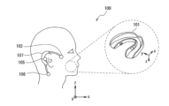
- FIG. 22 is a schematic configuration diagram of a system 100 according to the second embodiment of the present disclosure.
- the system 100 is a system that starts measures to control the intoxication state (measures to avoid or suppress the intoxication in advance, etc.) when a user (person to be measured) who is playing VR shows signs of intoxication. be.
- the system 100 includes a mouthpiece type device 101 and a GVS (Galvanic Vestibular Stimulation) device 102.
- the mouthpiece type device 101 is the mouthpiece type device 1 according to the first embodiment.
- the signal transmission destination of the transmitter 31 is the GVS device 102.
- the GVS device 102 (“external device” in a broad sense) is attached to each of the left and right ears of the person to be measured, receives a signal transmitted from the transmitter 31 of the mouthpiece type device 101, and uses the received signal as a trigger. , starts driving a function (in a broad sense, "predetermined function") that takes measures to control the state of motion sickness during VR play.
- the GVS device 102 may have a configuration including a communication section 103, a current application section 104, and electrodes 105, 106, and 107, as shown in FIG.
- the communication unit 103 then receives a signal transmitted from the transmitter 31 of the mouthpiece type device 101.
- the current applying unit 104 determines whether the concentration of enzyme (amylase) in the saliva 8 exceeds a predetermined threshold based on the signal received by the communication unit 103. In addition, if it is determined that the threshold has been exceeded, the current applying unit 104 applies a current to the head (in particular, the vestibular organ of the inner ear) of the subject through the electrodes 105 to 107 so as to suppress motion sickness during VR play. ).Start treatment by applying a weak current to the area. Electrodes 105-107 may be placed, for example, near the temple, in the neck area below the back of the ear, and near the mastoid process.
- the GVS device 102 (external device) receives a signal transmitted from the mouthpiece type device 101, and uses the received signal as a trigger to perform VR play.
- the system is configured to start driving a function (predetermined function) that performs treatment for controlling the state of motion sickness.
- a function predetermined function
- the concentration of enzyme (amylase) in the saliva 8 becomes high, it is possible to avoid or suppress the feeling of sickness. Therefore, it is possible to improve the sense of immersion of the person to be measured in VR.
- the system 100 is configured to include the GVS device 102, but other configurations may be used. For example, if it is determined that the concentration of enzyme (amylase) exceeds a threshold based on a signal transmitted from the transmitter 31 of the mouthpiece type device 101 instead of the GVS device 102, the It may also be configured to include a device that outputs images, video effects, vibrations, smells, sounds, etc. that suppress motion sickness.
- the mouthpiece type device 1 according to the first embodiment is used in the system 100 as the mouthpiece type device 101, but other configurations may be used. For example, a configuration using a mouthpiece type device 1 according to a modified example may be used.
- the present technology can also have the following configuration.
- a sensor module comprising: an enzyme sensor that is disposed on a wall surface of the storage chamber opposite to the movable wall or on a wall surface of the storage chamber opposite to the flow path side, and measures the concentration of enzyme in the liquid.
- the enzyme sensor is a sensor that measures the concentration of amylase as the concentration of the enzyme.
- the movable wall forms a wall surface of a first region that is a region on the flow path side of the region inside the storage chamber, and when the movable wall is deformed in a direction in which the volume of the storage chamber is reduced, the movable wall configured to contact a wall surface facing the wall to separate the flow path from a second region that is a region of the storage chamber on the opposite side to the flow path side;
- the sensor module according to any one of (1) to (4), wherein the enzyme sensor is disposed on the wall side of the second region.
- the inside of the second region is in a vacuum state or a low pressure state lower than atmospheric pressure in a state where the movable wall separates the second region and the flow path. sensor module.
- a mouthpiece type device comprising: a mouthpiece on which the sensor module is mounted.
- the mouthpiece type device (10) The mouthpiece type device according to (9) above, wherein the sensor module is mounted on a side wall surface or inside the side wall of the mouthpiece.
- the sensor module includes a plurality of sensor units including the flow path, the storage chamber, the movable wall, and the enzyme sensor,
- the mouthpiece type device according to (9) or (10) above, wherein each of the movable walls included in the plurality of sensor units is made to sequentially perform increase/decrease control to increase and decrease the volume of the accommodation chamber.
- the sensor module includes a plurality of sensor units including the flow path, the storage chamber, the movable wall, and the enzyme sensor, For each sensor unit group including two or more of the plurality of sensor units, the two or more movable walls included in the sensor unit group sequentially perform measurement operations that simultaneously perform increase/decrease control.
- the mouthpiece type device according to any one of (9) to (13), wherein the sensor module is configured to be removably attached to the mouthpiece.
- a system comprising: an external device that receives a signal transmitted from the mouthpiece-type device and starts driving a predetermined function using the received signal as a trigger.
- Power supply 31 ... Transmitter, 32...Vacuum region, 33...Flow path side region, 34...Sensor unit group, 35...Data average calculation circuit, 100...System, 101...Mouthpiece type device, 102...GVS device, 103...Communication section, 104...Current application section , 105, 106, 107... electrode
Landscapes
- Health & Medical Sciences (AREA)
- Life Sciences & Earth Sciences (AREA)
- Molecular Biology (AREA)
- Chemical & Material Sciences (AREA)
- Pathology (AREA)
- Physics & Mathematics (AREA)
- General Health & Medical Sciences (AREA)
- Engineering & Computer Science (AREA)
- Veterinary Medicine (AREA)
- Heart & Thoracic Surgery (AREA)
- Surgery (AREA)
- Animal Behavior & Ethology (AREA)
- Biomedical Technology (AREA)
- Public Health (AREA)
- Medical Informatics (AREA)
- Biophysics (AREA)
- Chemical Kinetics & Catalysis (AREA)
- Electrochemistry (AREA)
- Analytical Chemistry (AREA)
- Biochemistry (AREA)
- General Physics & Mathematics (AREA)
- Immunology (AREA)
- Investigating Or Analysing Biological Materials (AREA)
Abstract
検出対象の液体中の酵素の濃度を感度よく測定可能なセンサモジュールを提供する。一方の開口端が外部に向けて開口している流路と、流路を介してマウスピースのオリフィス内(外部)から唾液(検出対象の液体)を取得して収容する収容室と、収容室の上面(壁面)を形成し、収容室の容積が変化する方向に変形可能な可動壁と、収容室の可動壁と対向する底面側(壁面側)に配置され、収容室に収容された唾液(液体)中のアミラーゼ(酵素)の濃度を測定する酵素センサと、を備える構成とした。
Description
本開示は、センサモジュール、マウスピース型デバイス及びシステムに関する。
近年、ゲーム、アミューズメント、医療、教育等、幅広い分野でVR(Virtual Reality)の活用が進んでいる。VRは、ここ数年でモバイルと同等に市場規模が拡大することが期待され、世の中において一般的な技術として普及していくことが想定される。しかし、ユーザによっては、VRの継続プレイ時に、乗り物酔いに似た「酔い」を感じる場合もあった。そのため、VRの普及には、酔いの兆候を検出し、酔いを事前回避又は抑制する技術の開発が望まれている。この技術の開発では、特に、酔いの兆候の検出が重要となる。
例えば、特許文献1では、唾液中の酵素の1つであるアミラーゼが酔い兆候時の快・不快のトレーサーであることを利用し、口腔内の唾液中のアミラーゼ(酵素)の濃度を検出する機器が提案されている。具体的には、酵素と反応して電子を発生する電子発生カプセルと、その電子発生カプセルを保持する凹構造と、を備え、発生した電子による電流を測定することで、酵素の濃度を測定するセンサモジュールが提案されている。特許文献1に記載のセンサモジュールでは、凹構造の開口の遮蔽・開放を行う可動式の遮蔽板を更に備え、遮蔽板に凹構造の開口を開閉させることで、開口内への液体の導入を制御している。
ここで、特許文献1に記載のセンサモジュールでは、唾液中の酵素の濃度を検出する場合、センサモジュールをマウスピースの側壁面に実装し、その側壁面に形成したオリフィスを介して、口腔内の唾液をセンサモジュールの凹構造内に導入するようになっている。
しかし、遮蔽板の可動域を考慮すると、センサモジュールの設置位置はオリフィスからある程度の距離を取る必要がある。そのため、凹構造の開口を開放しても、唾液が凹構造の開口内に流入せず、唾液中の酵素の濃度の計測が適切に行われないない可能性がある。
しかし、遮蔽板の可動域を考慮すると、センサモジュールの設置位置はオリフィスからある程度の距離を取る必要がある。そのため、凹構造の開口を開放しても、唾液が凹構造の開口内に流入せず、唾液中の酵素の濃度の計測が適切に行われないない可能性がある。
本開示は、検出対象の液体中の酵素の濃度を感度よく測定可能なセンサモジュール、マウスピース型デバイス及びシステムを提供することを目的とする。
本開示のセンサモジュールは、(a)一方の開口端が外部に向けて開口している流路と、(b)流路を介して外部から検出対象の液体を取得して収容する収容室と、(c)収容室の壁面を形成し、収容室の容積が変化する方向に変形可能な可動壁と、(d)収容室の可動壁と対向する壁面側、又は収容室の流路側と反対側の壁面側に配置され、液体中の酵素の濃度を測定する酵素センサと、を備える。
本開示のマウスピース型デバイスは、(a)一方の開口端が外部に向けて開口している流路、(b)流路を介して外部から検出対象の液体を取得して収容する収容室、(c)収容室の壁面を形成し、収容室の容積が変化する方向に変形可能な可動壁、(d)並びに収容室の可動壁と対向する壁面側、又は収容室の流路側と反対側の壁面側に配置され、液体中の酵素の濃度を測定する酵素センサを備えるセンサモジュールと、(e)センサモジュールが実装されたマウスピースと、を備える。
本開示のシステムは、(a)一方の開口端が外部に向けて開口している流路、(b)流路を介して外部から検出対象の液体を取得して収容する収容室、(c)収容室の壁面を形成し、収容室の容積が変化する方向に変形可能な可動壁、(d)収容室の可動壁と対向する壁面側、又は収容室の流路側と反対側の壁面側に配置され、液体中の酵素の濃度を測定する酵素センサ、(e)並びに酵素センサから出力された信号を送信する送信機を備えるセンサモジュールと、(f)センサモジュールが実装されたマウスピースと、を備えるマウスピース型デバイスと、(g)マウスピース型デバイスから送信される信号を受信し、受信した信号をトリガーとして所定機能の駆動を開始する外部デバイスと、を備える。
以下に、本開示の実施形態に係るセンサモジュール、マウスピース型デバイス及びシステムの一例を、図1~図23を参照しながら説明する。本開示の実施形態は以下の順序で説明する。なお、本開示は以下の例に限定されるものではない。また、本明細書に記載された効果は例示であって限定されるものではなく、また他の効果があってもよい。
1.第1の実施形態:マウスピース型デバイス
1-1 マウスピース型デバイスの構成
1-2 変形例
2.第2の実施形態:システム
1-1 マウスピース型デバイスの構成
1-2 変形例
2.第2の実施形態:システム
〈1.第1の実施形態:マウスピース型デバイス〉
[1-1 マウスピース型デバイスの構成]
本開示の第1の実施形態に係るマウスピース型デバイス1について説明する。図1は、第1の実施形態に係るマウスピース型デバイス1の全体構成を示す図である。マウスピース型デバイス1は、VRをプレイ中のユーザを測定対象者とし、測定対象者に装着され、唾液中の酵素の濃度を連続測定し、VRの継続プレイ時の酔いの兆候を時系列モニタリングするためのデバイスである。酵素としては、例えば、アミラーゼが挙げられる。
図1に示すように、マウスピース型デバイス1は、マウスピース2を備えている。
マウスピース2は、測定対象者の下顎に着脱可能に装着される下顎用マウスピースである。下顎用マウスピースとすることにより、図2に示すように、交感神経系の刺激(ストレス起因)によって舌下腺やその他の小唾液腺から分泌される酵素(アミラーゼ)をより感度よく検出できる。図2は、図1のyz面と平行な面で破断した場合のマウスピース型デバイス1の断面構成を示す図である。マウスピース2は、下顎歯列のすべての歯の歯冠部と歯茎の上部とを覆うように、測定対象者の下顎歯列に合わせて平面視で略U字状に形成されている。マウスピース2としては、例えば、スポーツ用のマウスピースを採用できる。マウスピース2の厚さの一例としては、例えば3mm程度とする構成が挙げられる。
[1-1 マウスピース型デバイスの構成]
本開示の第1の実施形態に係るマウスピース型デバイス1について説明する。図1は、第1の実施形態に係るマウスピース型デバイス1の全体構成を示す図である。マウスピース型デバイス1は、VRをプレイ中のユーザを測定対象者とし、測定対象者に装着され、唾液中の酵素の濃度を連続測定し、VRの継続プレイ時の酔いの兆候を時系列モニタリングするためのデバイスである。酵素としては、例えば、アミラーゼが挙げられる。
図1に示すように、マウスピース型デバイス1は、マウスピース2を備えている。
マウスピース2は、測定対象者の下顎に着脱可能に装着される下顎用マウスピースである。下顎用マウスピースとすることにより、図2に示すように、交感神経系の刺激(ストレス起因)によって舌下腺やその他の小唾液腺から分泌される酵素(アミラーゼ)をより感度よく検出できる。図2は、図1のyz面と平行な面で破断した場合のマウスピース型デバイス1の断面構成を示す図である。マウスピース2は、下顎歯列のすべての歯の歯冠部と歯茎の上部とを覆うように、測定対象者の下顎歯列に合わせて平面視で略U字状に形成されている。マウスピース2としては、例えば、スポーツ用のマウスピースを採用できる。マウスピース2の厚さの一例としては、例えば3mm程度とする構成が挙げられる。
また、マウスピース2の歯冠部と接する面(以下、「内面」とも呼ぶ)のうちの、舌側又は口蓋側の壁面(以下、「第1壁面S1」とも呼ぶ)には、圧力センサ3と、センサモジュール4L,4Rと、ロジック部5(広義には「制御部」)とが配置されている。また、マウスピース2のセンサモジュール4L,4Rが配置される位置には、複数のオリフィス6が形成されている。図1では、センサモジュール4L,4Rが配置される位置それぞれに、オリフィス6として、マウスピース2の第1壁面S1を貫通する円筒状の貫通孔を6つ形成した場合を例示している。オリフィス6は、センサモジュール4L,4Rをマウスピース2に実装し、マウスピース2を測定対象者の下顎に装着した場合に、口腔内の唾液8がオリフィス6内に入り込み、オリフィス6内の唾液8が図11に示した流路12内に入り込むように、流路12の一方の開口端11と対向する位置に形成されている。
また、マウスピース2の内面のうちの、頬側又は唇側の壁面(以下、「第2壁面S2」とも呼ぶ)には、電源/RF部7が配置されている。なお、マウスピース2は、GPS受信機や加速度センサ等、外部環境を測定する機能が実装された構成としてもよい。
また、マウスピース2の内面のうちの、頬側又は唇側の壁面(以下、「第2壁面S2」とも呼ぶ)には、電源/RF部7が配置されている。なお、マウスピース2は、GPS受信機や加速度センサ等、外部環境を測定する機能が実装された構成としてもよい。
圧力センサ3は、マウスピース2の第1壁面S1のうちの、前歯の裏側と前歯の天面との両方に接する部分に配置されている。圧力センサ3は、マウスピース2の前歯の裏側に位置する部分や前歯の天面に位置する部分に加えられた圧力を検出する。これにより、測定対象者が舌で圧力センサ3を押したり、圧力センサ3を噛んだりすると、圧力に応じた信号が圧力センサ3から出力される。出力された信号は、ロジック部5に入力される。
センサモジュール4L,4Rは、マウスピース2の第1壁面S1のうちの、左右の奥歯の裏側に接する部分(以下、「奥歯接触部」とも呼ぶ)それぞれに配置されている。センサモジュール4L,4Rは、測定対象者の唾液8(広義には「測定対象の液体」)中の酵素(アミラーゼ)の濃度を測定する。なお、センサモジュール4L,4Rは、左右逆であるが同じ構造であるため、以下ではセンサモジュール4Lの構造についてのみ説明する。
センサモジュール4Lは、図3に示すように、センサモジュール4Lの各部品を収容する平板状の筐体9を備えている。以下、平板状のセンサモジュール4Lの厚さ方向(平板の厚さ方向)を「y方向」と呼び、平板状のセンサモジュール4Lの一方の辺(平板の一方の辺)に沿った方向を「x方向」と呼び、他方の辺(平板の他方の辺)に沿った方向を「z方向」と呼ぶ。筐体9は、xz面が第1壁面S1の奥歯接触部に沿い、z方向が上下方向(下側から上側に向かう方向)と平行となり、y方向が幅方向(頬側又は唇側から舌側又は口蓋側に向かう方向)と平行となるように、第1壁面S1の奥歯接触部に配置される。筐体9(センサモジュール4L)は、マウスピース2に着脱可能な構成となっている。例えば、図2に示すように、第1壁面S1の奥歯接触部に筐体9を嵌め込み可能な凹部2aを形成しておき、その凹部2aに筐体9を嵌め込んで固定する構成を採用できる。これにより、センサモジュール4Lを交換してマウスピース2を再利用可能となっている。
なお、第1の実施形態では、センサモジュール4Lを、マウスピース2の側壁面(第1壁面S1)に実装する例を示したが、他の構成を採用することもできる。例えば、図4に示すように、マウスピース2の側壁内に実装する構成としてもよい。
センサモジュール4Lは、図3に示すように、センサモジュール4Lの各部品を収容する平板状の筐体9を備えている。以下、平板状のセンサモジュール4Lの厚さ方向(平板の厚さ方向)を「y方向」と呼び、平板状のセンサモジュール4Lの一方の辺(平板の一方の辺)に沿った方向を「x方向」と呼び、他方の辺(平板の他方の辺)に沿った方向を「z方向」と呼ぶ。筐体9は、xz面が第1壁面S1の奥歯接触部に沿い、z方向が上下方向(下側から上側に向かう方向)と平行となり、y方向が幅方向(頬側又は唇側から舌側又は口蓋側に向かう方向)と平行となるように、第1壁面S1の奥歯接触部に配置される。筐体9(センサモジュール4L)は、マウスピース2に着脱可能な構成となっている。例えば、図2に示すように、第1壁面S1の奥歯接触部に筐体9を嵌め込み可能な凹部2aを形成しておき、その凹部2aに筐体9を嵌め込んで固定する構成を採用できる。これにより、センサモジュール4Lを交換してマウスピース2を再利用可能となっている。
なお、第1の実施形態では、センサモジュール4Lを、マウスピース2の側壁面(第1壁面S1)に実装する例を示したが、他の構成を採用することもできる。例えば、図4に示すように、マウスピース2の側壁内に実装する構成としてもよい。
筐体9の寸法の一例としては、例えば、z方向の長さを10mm、x方向の長さを10mm、y方向の長さを2mmとする構成が挙げられる。xz面を10mm×10mmとすることにより、側面視の大きさを、奥歯1本程度の大きさとすることができる。また、y方向の長さを2mmとすることにより、スポーツ用のマウスピース(比較的厚いマウスピース)の中に実装できる。筐体9の材料としては、例えば、樹脂を用いることができる。
また、筐体9の内部には、複数のセンサユニット10がアレイ状に配置されている。図3では、6個のセンサユニット10がz方向(図3では上下方向)に2列、x方向(図3では手前側から奥側に向かう方向)に3列のアレイ状に配置された場合を例示している。
また、センサユニット10は、図5に示すように、センサモジュール4Lのy方向側(図5では右側)の面に外部に向けて開口している一方の開口端11を有し、y方向と反対側に伸びている円筒状の流路12を備えている。これにより、センサモジュール4Lをマウスピース2に実装した場合に、流路12の一方の開口端11が第1壁面S1のオリフィス6内の空間に向けて開口する構成となっている。図5は、図3のyz面と平行な面で破断した場合のセンサユニット10の断面構成を示す図である。また、流路12の他方の開口端13は、センサユニット10内に形成された収容室14の内部に向けて開口されている。流路12の直径の一例としては、例えば、0.1mm程度とする構成が挙げられる。
また、センサユニット10は、図5に示すように、センサモジュール4Lのy方向側(図5では右側)の面に外部に向けて開口している一方の開口端11を有し、y方向と反対側に伸びている円筒状の流路12を備えている。これにより、センサモジュール4Lをマウスピース2に実装した場合に、流路12の一方の開口端11が第1壁面S1のオリフィス6内の空間に向けて開口する構成となっている。図5は、図3のyz面と平行な面で破断した場合のセンサユニット10の断面構成を示す図である。また、流路12の他方の開口端13は、センサユニット10内に形成された収容室14の内部に向けて開口されている。流路12の直径の一例としては、例えば、0.1mm程度とする構成が挙げられる。
また、センサユニット10は、図5及び図6に示すように、流路12の他方の開口端13が内部に向けて開口された収容室14を備えている。収容室14は、後述するように可動壁15が湾曲状態となった場合に、y方向(即ち、流路12と同一の方向)に沿って伸びた半円筒状の空間となる。これにより、オリフィス6内の唾液8が流路12内に入り込み、入り込んだ唾液8が流路12内を流れることが可能となっており、流路12を介して外部から収容室14内に唾液8を取得して収容することが可能となっている。また、収容室14及び流路12のz方向側と反対側(図5では下側)の高さは同一となっている。また、収容室14及び流路12のz方向側(図5では上側)の高さも同一となっている。
収容室14の寸法の一例としては、例えば、x方向の長さを1mm、y方向の長さを1mm、z方向の長さ(底部から頂部までの高さ)を0.1mmとする構成が挙げられる。
収容室14の寸法の一例としては、例えば、x方向の長さを1mm、y方向の長さを1mm、z方向の長さ(底部から頂部までの高さ)を0.1mmとする構成が挙げられる。
また、収容室14のz方向側(図5では上側)の壁面は、収容室14の容積が変化する方向に変形可能な可動壁15で形成されている。
具体的には、可動壁15は、図6及び図7に示すように、一対のソフト電極16,17と、一対のソフト電極16,17で挟まれた強磁性体18とを備えている。そして、一対のソフト電極16,17間に電圧が印加されると、可動壁15のx方向(流路12が伸びている方向と直交する方向)の中央部がz方向(図5では上方向)に突出した半円筒状となるように変形した状態(以下、「湾曲状態」とも呼ぶ)となる。即ち、一対のソフト電極16,17間に電圧が加わることで、強磁性体18内部が分極してマックスウェル応力が発生し、可動壁15のx方向の中央部がz方向に突出するように可動壁15が湾曲する。これにより、収容室14が半円筒状の空間となり、収容室14の容積が最大となる。
強磁性体18としては、例えば、強磁性体を含む導電ポリマーを採用できる。また、一対のソフト電極16,17としては、例えば、カーボンブラックの電極を採用できる。
なお、可動壁15としては、例えば、鉛フリーの強磁性体材料を用いたピエゾ素子を用いることもできる。強磁性体材料としては、例えば、ビスマス(Bi)を含有する合金を採用できる。また、可動壁15としては、例えば、形状記憶合金を用いることもできる。
具体的には、可動壁15は、図6及び図7に示すように、一対のソフト電極16,17と、一対のソフト電極16,17で挟まれた強磁性体18とを備えている。そして、一対のソフト電極16,17間に電圧が印加されると、可動壁15のx方向(流路12が伸びている方向と直交する方向)の中央部がz方向(図5では上方向)に突出した半円筒状となるように変形した状態(以下、「湾曲状態」とも呼ぶ)となる。即ち、一対のソフト電極16,17間に電圧が加わることで、強磁性体18内部が分極してマックスウェル応力が発生し、可動壁15のx方向の中央部がz方向に突出するように可動壁15が湾曲する。これにより、収容室14が半円筒状の空間となり、収容室14の容積が最大となる。
強磁性体18としては、例えば、強磁性体を含む導電ポリマーを採用できる。また、一対のソフト電極16,17としては、例えば、カーボンブラックの電極を採用できる。
なお、可動壁15としては、例えば、鉛フリーの強磁性体材料を用いたピエゾ素子を用いることもできる。強磁性体材料としては、例えば、ビスマス(Bi)を含有する合金を採用できる。また、可動壁15としては、例えば、形状記憶合金を用いることもできる。
また、可動壁15は、図7に示すように、一対のソフト電極16,17間への電圧の印加が停止されると、可動壁15が平板状となるように変形した状態(以下、「平板状態」とも呼ぶ)となる。図7では、可動壁15が平板状態であるときに、可動壁15のz方向側と反対側の面(図6では、下側の面。以下、「下面S3」とも呼ぶ)と、収容室14のz方向側と反対側の壁面(図6では、下側の壁面。以下、「底面S4」とも呼ぶ)とが接触して、図8に示した酵素センサ19の凹構造22の開口を覆う場合を例示している。
即ち、可動壁15は、収容室14の容積が小さくなる方向に可動壁15が変形したときに、酵素センサ19に接触して、凹構造22内に配置された電子発生カプセル24(広義には「反応部」。図8参照)を覆うように構成されている。これにより、収容室14の容積がゼロとなり、収容室14の容積が最小となる。また、酵素センサ19の電子発生カプセル24(反応部)が可動壁15で覆われて唾液8に接触しないため、酵素センサ19による酵素(アミラーゼ)の濃度の測定が開始されずに済む。また、可動壁15のz方向の厚さは、可動壁15が平板状態であるときに、可動壁15の側面で流路12の収容室14側の開口端(他方の開口端13)を塞ぐことができるように流路12の直径以上とした。
即ち、可動壁15は、収容室14の容積が小さくなる方向に可動壁15が変形したときに、酵素センサ19に接触して、凹構造22内に配置された電子発生カプセル24(広義には「反応部」。図8参照)を覆うように構成されている。これにより、収容室14の容積がゼロとなり、収容室14の容積が最小となる。また、酵素センサ19の電子発生カプセル24(反応部)が可動壁15で覆われて唾液8に接触しないため、酵素センサ19による酵素(アミラーゼ)の濃度の測定が開始されずに済む。また、可動壁15のz方向の厚さは、可動壁15が平板状態であるときに、可動壁15の側面で流路12の収容室14側の開口端(他方の開口端13)を塞ぐことができるように流路12の直径以上とした。
また、センサユニット10には、収容室14の可動壁15と対向する壁面(底面S4)側(図5では下側)に酵素センサ19が配置されている。酵素センサ19は、収容室14の底面S4を形成している。酵素センサ19は、収容室14に収容された唾液8中の酵素(アミラーゼ)の濃度を測定する。これにより、センサモジュール4Lの外部から収容室14内に唾液8が収容されると、収容された唾液8中の酵素(アミラーゼ)の濃度に応じた信号が酵素センサ19から出力される。出力された信号はロジック部5に入力される。
具体的には、酵素センサ19は、図8に示すように、一対の電極20,21と、一対の電極20,21で挟持され、凹構造22を有する電子伝達層23と、凹構造22の内部に保持された電子発生カプセル24とを備えている。そして、電子発生カプセル24で発生した電子による電流を測定することで、酵素(アミラーゼ)の量を測定可能となっている。一対の電極20,21としては、例えば、Ag電極、C電極を採用できる。また、電子伝達層23としては、例えば、ゲル状のメディエータを含む層を採用できる。例えば、ゲル化したフェリシアン化カリウム溶液(電解質)を含む層が挙げられる。また、電子発生カプセル24としては、例えば、グルコースオキシダーゼ、マルターゼ及びPMEHを含む球状の中心部25をでんぷんの薄膜26で包んだ球状のでんぷんボールを採用できる。電子発生カプセル24(デンプンボール)とゲル状のメディエータとは、酵素センサ19の反応部を構成する。これにより、唾液8中の酵素は、でんぷんとの反応を起点とした酸化・還元反応により、一対の電極20,21のうちの+電極側から電子を生成する。
具体的には、酵素センサ19は、図8に示すように、一対の電極20,21と、一対の電極20,21で挟持され、凹構造22を有する電子伝達層23と、凹構造22の内部に保持された電子発生カプセル24とを備えている。そして、電子発生カプセル24で発生した電子による電流を測定することで、酵素(アミラーゼ)の量を測定可能となっている。一対の電極20,21としては、例えば、Ag電極、C電極を採用できる。また、電子伝達層23としては、例えば、ゲル状のメディエータを含む層を採用できる。例えば、ゲル化したフェリシアン化カリウム溶液(電解質)を含む層が挙げられる。また、電子発生カプセル24としては、例えば、グルコースオキシダーゼ、マルターゼ及びPMEHを含む球状の中心部25をでんぷんの薄膜26で包んだ球状のでんぷんボールを採用できる。電子発生カプセル24(デンプンボール)とゲル状のメディエータとは、酵素センサ19の反応部を構成する。これにより、唾液8中の酵素は、でんぷんとの反応を起点とした酸化・還元反応により、一対の電極20,21のうちの+電極側から電子を生成する。
なお、酵素センサ19としては、例えば、図9に示すように、一対の電極27,28と、一対の電極27,28で挟持された電子発生層29とを備える酵素センサを用いることもできる。このような酵素センサ19によれば、電子発生層29で発生した電子による電流を測定することで、酵素(アミラーゼ)の量を測定できる。電子発生層29としては、例えばでんぷん、PQQグルコース脱水素酵素及びメディエータを含む層を採用できる。
以上の構成を有するセンサユニット10では、酵素(アミラーゼ)の濃度測定を行わないときには、一対のソフト電極16,17間に電圧を印加せず、図7及び図10に示すように、可動壁15を平板状態とする。そして、流路12の他方の開口端13を可動壁15の側面で塞ぐとともに、収容室14の底面S4を可動壁15の下面S3で覆う。これにより、収容室14内に唾液8が入ることがなく、酵素センサ19が唾液8に触れずに済む。
一方、酵素(アミラーゼ)の濃度測定を行うときには、一対のソフト電極16,17間に電圧を印加し、図6及び図11に示すように、可動壁15を湾曲状態とする。そして、可動壁15が湾曲状態になると、可動壁15の側面で塞がれていた流路12の他方の開口端13が開放されるとともに、可動壁15の下面S3で覆われていた収容室14の底面S4が露出される。また、湾曲状態になることで、収容室14の容積が増大し、容積の増大によって収容室14内に陰圧が発生する。これにより、収容室14内に発生した陰圧によって、オリフィス6内の唾液8が流路12内に引き込まれ、引き込まれた唾液8が流路12を介して収容室14内に収容される。そして、収容室14内に唾液8が収容されると、収容された唾液8中の酵素(アミラーゼ)の濃度が酵素センサ19で計測される。
なおその際、収容室14内に陰圧が発生するため、口腔内に酵素センサ19の電子発生カプセル24(反応部)の材料が染み出すことを抑制することもできる。
なおその際、収容室14内に陰圧が発生するため、口腔内に酵素センサ19の電子発生カプセル24(反応部)の材料が染み出すことを抑制することもできる。
ここで、流路12が伸びている方向(図5では左右方向)における、流路12の長さLaは、収容室14の長さLbよりも短くすることが好ましい(La<Lb)。これにより、可動壁15で収容室14の容積を増大させ、陰圧を発生させたときに、唾液8を瞬時(例えば、10-6秒)に収容室14内に収容でき、唾液8中の酵素(アミラーゼ)の濃度の計測を瞬時に開始できる。La<Lbとすることで、収容室14の容積の増大による陰圧によって唾液8を瞬時に収容室14内に収容できることは、図12及び図13に示すように、液面移動のシミュレーション結果によって把握される。即ち、図10に示すように、収容室14の容積が最小となる位置に可動壁15があるとき(平板状態)における、口腔内での唾液8の圧力をP0、唾液8の粘性をμ、流路12での圧力をP2、流路12及び収容室14のz方向の長さをaとした場合、唾液8の移動速度vは、下記(1)式で表される。

また、図11に示すように、収容室14の容積が最大となる形状に可動壁15が変形してからの経過時間tにおける、唾液8の移動速度v(t)は、下記(2)式で表される。

ここで、V0は可動壁15が平板状態であるときの流路12内の空気の体積であり、V(0)は可動壁15が湾曲状態であるときの収容室14の体積である。
そして、上記(2)式に従い、液面移動のシミュレーションを行い、図12及び図13に示したシミュレーション結果を得た。図12は、La=0.1mm、Lb=1.0mmとした場合のシミュレーション結果である。また、図13は、La=0.5mm、Lb=0.5mmとした場合のシミュレーション結果である。図12及び図13では、縦軸は唾液8の移動距離を表しており、横軸は可動壁15が平板状態から湾曲状態となってからの経過時間tを表している。図12によれば、La<Lbの場合に、収容室14の入り口(他方の開口端13)から0.9mmの位置まで唾液8が瞬時に到達することがわかる。また、図13によれば、La=Lbの場合に、収容室14の他方の開口端13までは唾液8が瞬時に到達するが、陰圧だけでは収容室14内には唾液8が入っていかないことがわかる。
なお、図13に示したLa=Lbの場合でも、実際には、測定対象者の動き等にともなって唾液8に各種の力が加わるため、収容室14の他方の開口端13まで到達した唾液8は、収容室14の内部に広がっていき、酵素センサ19に到達することが期待できる。
そして、上記(2)式に従い、液面移動のシミュレーションを行い、図12及び図13に示したシミュレーション結果を得た。図12は、La=0.1mm、Lb=1.0mmとした場合のシミュレーション結果である。また、図13は、La=0.5mm、Lb=0.5mmとした場合のシミュレーション結果である。図12及び図13では、縦軸は唾液8の移動距離を表しており、横軸は可動壁15が平板状態から湾曲状態となってからの経過時間tを表している。図12によれば、La<Lbの場合に、収容室14の入り口(他方の開口端13)から0.9mmの位置まで唾液8が瞬時に到達することがわかる。また、図13によれば、La=Lbの場合に、収容室14の他方の開口端13までは唾液8が瞬時に到達するが、陰圧だけでは収容室14内には唾液8が入っていかないことがわかる。
なお、図13に示したLa=Lbの場合でも、実際には、測定対象者の動き等にともなって唾液8に各種の力が加わるため、収容室14の他方の開口端13まで到達した唾液8は、収容室14の内部に広がっていき、酵素センサ19に到達することが期待できる。
電源/RF部7は、電源30と、送信機31とを備えている。電源30は、ロジック部5及び送信機31に電力を供給する電源である。電源30としては、例えば、10V程度の電圧を出力できるリチウムイオン電池を採用できる。また、送信機31は、ロジック部5によって制御され、無線通信又は有線通信によって外部機器に信号を送信する。無線通信としては、例えばBluetooth(登録商標)等の無線通信規格による通信を採用できる。
ロジック部5は、圧力センサ3から出力された信号の取得、可動壁15の駆動、酵素センサ19から出力された信号の取得、送信機31を介した外部装置への信号の送信を行う。ロジック部5としては、例えば、トランジスタを含む集積回路を用いることができる。
具体的には、図14に示すように、測定対象者が舌で圧力センサ3を押したり圧力センサ3を噛んだりし、圧力センサ3から圧力に応じた信号が入力されると、ロジック部5が、センサモジュール4L,4Rを起動させる(ステップS101)。続いて、ロジック部5が、図15の時刻t1に示すように、センサモジュール4Lの6個のセンサユニット10のうちの、1個のセンサユニット10(以下、「第1センサユニット10」とも呼ぶ)の可動壁15の一対のソフト電極16,17間への電圧の印加を開始する(ステップS102)。即ち、ロジック部5を構成するトランジスタが、可動壁15を湾曲状態に変形させる電圧(例えば、2V)を一分間継続的に印加する。電圧の印加により、ロジック部5が、可動壁15を湾曲状態に変形させ、収容室14の容積を増大させる(ステップS103)。これにより、収容室14内に陰圧が発生し、オリフィス6内の唾液8が流路12を介して収容室14に引き込まれる。そして、第1センサユニット10の酵素センサ19では、唾液8と電子発生カプセル24(反応部)との反応が開始され、唾液8中の酵素(アミラーゼ)の濃度(アミラーゼ活性)の測定が開始される(ステップS104)。
具体的には、図14に示すように、測定対象者が舌で圧力センサ3を押したり圧力センサ3を噛んだりし、圧力センサ3から圧力に応じた信号が入力されると、ロジック部5が、センサモジュール4L,4Rを起動させる(ステップS101)。続いて、ロジック部5が、図15の時刻t1に示すように、センサモジュール4Lの6個のセンサユニット10のうちの、1個のセンサユニット10(以下、「第1センサユニット10」とも呼ぶ)の可動壁15の一対のソフト電極16,17間への電圧の印加を開始する(ステップS102)。即ち、ロジック部5を構成するトランジスタが、可動壁15を湾曲状態に変形させる電圧(例えば、2V)を一分間継続的に印加する。電圧の印加により、ロジック部5が、可動壁15を湾曲状態に変形させ、収容室14の容積を増大させる(ステップS103)。これにより、収容室14内に陰圧が発生し、オリフィス6内の唾液8が流路12を介して収容室14に引き込まれる。そして、第1センサユニット10の酵素センサ19では、唾液8と電子発生カプセル24(反応部)との反応が開始され、唾液8中の酵素(アミラーゼ)の濃度(アミラーゼ活性)の測定が開始される(ステップS104)。
続いて、ロジック部5が、第1センサユニット10の酵素センサ19から出力される信号(唾液8と電子発生カプセル24との反応によって発生した電子による電気信号)を1分間蓄積し、蓄積した1分間の信号を送信機31を介して外部装置に送信する(ステップS105)。続いて、ロジック部5が、図15の時刻t2に示すように、第1センサユニット10の一対のソフト電極16,17間(可動壁15)への電圧の印加を停止し(ステップS106)、制御対象を第1センサユニット10から次のセンサユニット10(第iセンサユニット。iは2~6の何れか)に切り替え(ステップS107)、ステップS102~S106のフローを繰り返す。即ち、ロジック部5を構成するトランジスタが、図15の時刻t3等に示すように、複数のセンサユニット10の可動壁15それぞれに、2Vの電圧を1分ずつ印加し、酵素センサ19による酵素(アミラーゼ)の濃度の測定を行わせる。換言すると、ロジック部5は、複数のセンサユニット10に含まれる可動壁15のうちの、1つの可動壁15に、収容室14の容積を増大及び減少させる増減制御を行わせるとともに、所定時間(1分)が経過するたびに、増減制御を行わせる可動壁15を切り替えている、とも言える。これにより、センサモジュール4Lの6個のセンサユニット10を順番に用いて、口腔内の唾液8の酵素(アミラーゼ)の濃度を連続測定できる。
また、下顎の左側に位置するセンサモジュール4Lの6個のセンサユニット10による測定を終えた後、下顎の右側に位置するセンサモジュール4Rの6個のセンサユニット10に対しても、図14に示したステップS102~S106のフローを同様に繰り返す。即ち、ロジック部5が、センサモジュール4L,4Rを構成する複数のセンサユニット10の可動壁15それぞれに、増減制御を順番に行わせる。これにより、センサモジュール4Rの6個のセンサユニット10を順番に用いて、センサモジュール4Lによる連続測定に続いて、口腔内の唾液8の酵素の濃度の連続測定を行うことができる。
なおその際、センサモジュール4L,4Rのそれぞれでは、制御対象とするセンサユニット10(つまり、酵素の濃度の測定を行うセンサユニット10)は、奥歯側から前歯側に順次切り替えように構成する。ここで、唾液8は、口腔内の舌下腺から分泌される。それゆえ、濃度測定の初期段階において、舌下腺に近い奥歯側のセンサユニット10を用いることで、唾液8中の酵素(アミラーゼ)の濃度を感度よく測定できる。また、舌下腺から分泌された唾液8は、時間経過にともなって口腔内に広がっていく。そのため、濃度測定の中期段階・後期段階においては、舌下腺から遠い前歯側のセンサユニット10を用いるようにしても、唾液8中の酵素(アミラーゼ)の濃度の測定の感度は低下せずに済む。
ここで、例えば、酵素センサ19の凹構造22の遮蔽・開放を行う可動式の遮蔽板を備え、遮蔽板に凹構造22の開口を開閉させることで、開口内への唾液8の導入を制御する構成を採用した場合を考える。このような構成によれば、遮蔽板の可動域を考慮すると、センサモジュール4L,4Rの設置位置は、オリフィス6からある程度の距離を取る必要がある。そのため、凹構造22の開口を開放しても、唾液8が凹構造22の開口内に流入せず、唾液8中のアミラーゼ(酵素)の濃度の計測が適切に行われない可能性がある。
これに対し、第1の実施形態に係るセンサモジュール4L,4R及びマウスピース型デバイス1では、一方の開口端11が外部に向けて開口している流路12と、流路12を介して外部から唾液8(検出対象の液体)を収容する収容室14とを備える構成とした。また、収容室14のz方向側の壁面を形成し、z方向に沿った方向(収容室14の容積が変化する方向)に変形可能な可動壁15と、収容室14の底面S4側(可動壁15と対向する壁面側)に配置され、唾液8中のアミラーゼ(酵素)の濃度を測定する酵素センサ19とを備える構成とした。これらの構成により、収容室14の容積を増大させ、収容室14内に陰圧を発生でき、収容室14の外部に存在する唾液8を流路12を介して収容室14内に引き込むことができる。そして、引き込んだ唾液8中のアミラーゼ(酵素)の濃度を酵素センサ19で測定できる。それゆえ、唾液8中のアミラーゼ(酵素)の濃度を感度よく測定可能なセンサモジュール4L,4R及びマウスピース型デバイス1を提供できる。
また、例えば、クロモゲンを含む試薬を用い、唾液8中のアミラーゼと試薬中のクロモゲンとの化学反応(CNP側鎖の形成)による試薬の色の変化を光学的に判定し、唾液8中のアミラーゼの濃度を測定する手法を採用した場合を考える。具体的には、ニプロ株式会社の「乾式臨床化学分析装置 唾液アミラーゼモニター」を用いて、30秒の間、試薬を舌下に押し当て、その後、口から試薬を取り出して、専用の測定器に試薬を挿入して光学的に測定を行う場合を考える。このような手法によれば、測定のたびに口腔内に試薬を入れ、その後、測定器に試薬を挿入して測定するために、アミラーゼの濃度を連続測定できず、VRプレイ時の酔い兆候を時系列モニタリングすることができない。また、舌下への試薬の押し当て方にコツが必要とされ、アミラーゼの濃度の正確な測定が難しい。
これに対し、第1の実施形態に係るマウスピース型デバイス1では、複数のセンサユニット10をアレイ状に配置してセンサモジュール4L,4Rをマウスピース2に実装した。そして、各センサユニット10が順番にアミラーゼ(酵素)の濃度の測定を行う構成とした。これにより、マウスピース2を測定対象者の下顎に装着することで、アミラーゼの濃度を連続測定でき、酔い兆候の時系列モニタリングを長時間行うことができる。
[1-2 変形例]
(1)なお、第1の実施形態では、酵素センサ19を可動壁15と対向する壁面(底面S4)に配置する例を示したが、他の構成を採用することもできる。例えば、図16及び図17に示すように、酵素センサ19を、収容室14の底面S4に加え、収容室14の側壁面S5(収容室14の壁面のうちの、x方向側の壁面、x方向側と反対側の壁面、及びy方向側と反対側の壁面)を形成するように凹形状の酵素センサを配置する構成としてもよい。これにより、収容室14内に唾液8が収容された場合に、収容された唾液8と酵素センサ19との接触面積を増大でき、酵素センサ19の感度を向上できる。図17は、図16のxy面と平行な面で破断した場合のセンサユニット10の断面構成を示す図である。図17では、流路12がy方向に沿って伸びている角筒状である場合を例示している。
(1)なお、第1の実施形態では、酵素センサ19を可動壁15と対向する壁面(底面S4)に配置する例を示したが、他の構成を採用することもできる。例えば、図16及び図17に示すように、酵素センサ19を、収容室14の底面S4に加え、収容室14の側壁面S5(収容室14の壁面のうちの、x方向側の壁面、x方向側と反対側の壁面、及びy方向側と反対側の壁面)を形成するように凹形状の酵素センサを配置する構成としてもよい。これにより、収容室14内に唾液8が収容された場合に、収容された唾液8と酵素センサ19との接触面積を増大でき、酵素センサ19の感度を向上できる。図17は、図16のxy面と平行な面で破断した場合のセンサユニット10の断面構成を示す図である。図17では、流路12がy方向に沿って伸びている角筒状である場合を例示している。
(2)また、例えば、酵素センサ19を、収容室14の流路12側と反対側の壁面側に配置する構成としてもよい。具体的には、図18に示すように、酵素センサ19を、収容室14内の領域のうちの流路12と反対側の領域(以下、「真空領域32」とも呼ぶ。広義には「第2領域」)の壁面側に配置する構成としてもよい。図18では、可動壁15が平板状態のときに、流路12と真空領域32とを可動壁15が分断するように、収容室14内の領域のうちの流路12側の領域(以下、「流路側領域33」とも呼ぶ。広義には「第1領域」)にのみ、可動壁15が形成されている場合を例示している。即ち、可動壁15は、収容室14内の流路側領域33の壁面を形成し、収容室14の容積が小さくなる方向に可動壁15が変形したときに(平板状態であるときに)、可動壁15と対向する壁面(底面S4)に接触して、真空領域32と流路12とを分断するように構成されている。これにより、酵素センサ19による酵素(アミラーゼ)の濃度の測定が開始されずに済む。
また、真空領域32内は、可動壁15が流路12と真空領域32とを分断している状態において、真空状態、又は大気圧よりも低い低圧状態となっている。真空領域32の真空状態は、例えば、センサモジュール4L,4Rが真空状態又は低圧状態の環境下で製造されることで実現される。これにより、図19に示すように、可動壁15が平板状態から湾曲状態に変形した場合に、収容室14の容積の変形によって収容室14内に発生した陰圧と、真空領域32の真空状態による陰圧とによって、オリフィス6内の唾液8を流路12及び流路側領域33を介して真空領域32に引き込むことができる。そして、真空領域32の周囲を囲むように酵素センサ19を配置したために、引き込んだ唾液8と酵素センサ19との接触面積を増大でき、酵素センサ19の感度を向上することができる。
(3)また、第1の実施形態では、ロジック部5が、センサモジュール4L,4Rを構成する複数のセンサユニット10の可動壁15それぞれに、収容室14の容積を増大させる方向に変形させた後に減少させる方向に変形させる増減制御を順番に行わせる例を示したが、他の構成を採用することもできる。例えば、図20に示すように、ロジック部5が、複数のセンサユニット10のうちの2以上のセンサユニット10を含んで構成されるセンサユニット群34それぞれに、測定動作を順番に行わせる構成としてもよい。測定動作としては、例えば、センサユニット群34に含まれる2以上のセンサユニット10の可動壁15が増減制御を同時に行う動作が挙げられる。図20では、アレイ状に配置された複数のセンサユニット10のうちz方向(図20では上下方向)に並んだ2つのセンサユニット10からなるセンサユニット群34が、x方向(図20では手前側から奥側に向かう方向)に3つ並んでいる場合を例示している。また、ロジック部5は、センサユニット群に含まれる2以上の酵素センサ19から出力される測定結果の平均を演算するデータ平均演算回路35を備える構成となっている。即ち、ある測定時間において、アレイ中の2以上のセンサユニット10を用いて同時に酵素の濃度の測定を行い、測定結果(酵素センサ19からの信号)の平均化を行って、平均化後の測定結果を出力する構成となっている。これにより、信号強度を増大でき、酵素センサ19の検出感度を向上できる。さらに、信号に含まれるノイズ成分を低減でき、酵素センサ19の検出精度を向上できる。
(4)また、第1の実施形態では、流路12を円筒状とする例(つまり、流路12の一方の開口端11の開口面積と他方の開口端13の開口面積とを同一とする例)を示したが、他の構成を採用することもできる。例えば、図21に示すように、流路12の外部側の開口端(一方の開口端11)の開口面積を収容室14側の開口端(他方の開口端13)の開口面積よりも小さくしてもよい。例えば、流路12の形状を円錐台状とする場合、流路12の外部側の開口端(一方の開口端11)の直径を、収容室14側の開口端(他方の開口端13)の直径(例えば、数十μm~1mm程度)の50%程度の大きさとする構成が挙げられる。これにより、口腔内から流路12内への唾液8の引き込み能力を向上できる。
〈2.第2の実施形態:システム〉
次に、本開示の第2の実施形態に係るシステム100について説明する。図22は、本開示の第2の実施形態に係るシステム100の概略構成図である。システム100は、VRをプレイ中のユーザ(測定対象者)に酔いの兆候がある場合に、酔い状態を制御するための処置(酔いを事前回避又は抑制するための処置等)を開始するシステムである。
図22に示すように、システム100は、マウスピース型デバイス101と、GVS(Galvanic Vestibular Stimulation)デバイス102とを備えている。
マウスピース型デバイス101は、第1の実施形態に係るマウスピース型デバイス1である。ただし、送信機31の信号送信先は、GVSデバイス102となっている。
次に、本開示の第2の実施形態に係るシステム100について説明する。図22は、本開示の第2の実施形態に係るシステム100の概略構成図である。システム100は、VRをプレイ中のユーザ(測定対象者)に酔いの兆候がある場合に、酔い状態を制御するための処置(酔いを事前回避又は抑制するための処置等)を開始するシステムである。
図22に示すように、システム100は、マウスピース型デバイス101と、GVS(Galvanic Vestibular Stimulation)デバイス102とを備えている。
マウスピース型デバイス101は、第1の実施形態に係るマウスピース型デバイス1である。ただし、送信機31の信号送信先は、GVSデバイス102となっている。
GVSデバイス102(広義には「外部デバイス」)は、測定対象者の左右の耳それぞれに装着され、マウスピース型デバイス101の送信機31から送信される信号を受信し、受信した信号をトリガーとして、VRプレイ中の酔い状態を制御するための処置を行う機能(広義には「所定機能」)の駆動を開始する。例えば、GVSデバイス102は、図23に示すように、通信部103、電流印加部104、及び電極105,106,107を備える構成としてもよい。そして、通信部103が、マウスピース型デバイス101の送信機31から送信される信号を受信する。また、電流印加部104が、通信部103が受信した信号に基づき、唾液8中の酵素(アミラーゼ)の濃度が予め定められた閾値を超えたかを判定する。また、閾値を超えたと判定した場合には、電流印加部104が、電極105~107を介して、VRプレイ中の酔いが抑制されるように測定対象者の頭部(特に、内耳の前庭器官)に微弱電流を流す処置を開始する。電極105~107は、例えば、こめかみ付近、耳裏の下の首部分、及び乳様突起付近に配置してもよい。
以上説明したように、第2の実施形態に係るシステム100では、GVSデバイス102(外部デバイス)が、マウスピース型デバイス101から送信される信号を受信し、受信した信号をトリガーとして、VRプレイ中の酔い状態を制御するための処置を行う機能(所定機能)の駆動を開始する構成とした。これにより、例えば、唾液8中の酵素(アミラーゼ)の濃度が高くなった場合に、酔いを事前回避することや、酔いを抑制することができる。それゆえ、測定対象者のVRへの没入感を向上させることができる。
なお、第2の実施形態では、システム100を、GVSデバイス102を備える構成とする例を示したが、他の構成としてもよい。例えば、GVSデバイス102に代えて、マウスピース型デバイス101の送信機31から送信される信号を基に、酵素(アミラーゼ)の濃度が閾値を超えたと判定した場合に、VRの映像と連動して酔いを抑制する映像、映像エフェクト、振動、匂い、音声等を出力するデバイスを備える構成としてもよい。
また、第2の実施形態では、マウスピース型デバイス101として、第1の実施形態に係るマウスピース型デバイス1をシステム100に用いる構成としたが、他の構成としてもよい。例えば、変形例に係るマウスピース型デバイス1を用いる構成としてもよい。
また、第2の実施形態では、マウスピース型デバイス101として、第1の実施形態に係るマウスピース型デバイス1をシステム100に用いる構成としたが、他の構成としてもよい。例えば、変形例に係るマウスピース型デバイス1を用いる構成としてもよい。
なお、本技術は、以下のような構成も取ることができる。
(1)
一方の開口端が外部に向けて開口している流路と、
前記流路を介して外部から検出対象の液体を取得して収容する収容室と、
前記収容室の壁面を形成し、前記収容室の容積が変化する方向に変形可能な可動壁と、
前記収容室の前記可動壁と対向する壁面側、又は前記収容室の前記流路側と反対側の壁面側に配置され、前記液体中の酵素の濃度を測定する酵素センサと、を備える
センサモジュール。
(2)
前記酵素センサは、前記酵素の濃度として、アミラーゼの濃度を測定するセンサである
前記(1)に記載のセンサモジュール。
(3)
前記流路の長さは、前記流路が伸びている方向における、前記収容室の長さよりも短い
前記(1)又は(2)に記載のセンサモジュール。
(4)
前記流路の前記一方の開口端の開口面積は、前記流路の前記収容室側に位置する他方の開口端の開口面積よりも小さい
前記(1)から(3)の何れかに記載のセンサモジュール。
(5)
前記酵素センサは、前記収容室の前記可動壁と対向する壁面側に配置され、
前記可動壁は、前記収容室の容積が小さくなる方向に前記可動壁が変形したときに、前記酵素センサに接触して、前記酵素センサの反応部を覆うように構成されている
前記(1)から(4)の何れかに記載のセンサモジュール。
(6)
前記可動壁は、前記収容室内の領域のうちの前記流路側の領域である第1領域の壁面を形成し、前記収容室の容積が小さくなる方向に前記可動壁が変形したときに、前記可動壁と対向する壁面に接触して、前記収容室内の領域のうちの前記流路側と反対側の領域である第2領域と前記流路とを分断するように構成され、
前記酵素センサは、前記第2領域の壁面側に配置されている
前記(1)から(4)の何れかに記載のセンサモジュール。
(7)
前記第2領域内は、前記可動壁が前記第2領域と前記流路とを分断している状態において、真空状態、又は大気圧よりも低い低圧状態となっている
前記(6)に記載のセンサモジュール。
(8)
前記流路、前記収容室及び前記酵素センサを含むセンサユニットを複数備え、
複数の前記センサユニットは、アレイ状に配置されている
前記(1)から(7)の何れかに記載のセンサモジュール。
(9)
一方の開口端が外部に向けて開口している流路、前記流路を介して外部から検出対象の液体を取得して収容する収容室、前記収容室の壁面を形成し、前記収容室の容積が変化する方向に変形可能な可動壁、並びに前記収容室の前記可動壁と対向する壁面側、又は前記収容室の前記流路側と反対側の壁面側に配置され、前記液体中の酵素の濃度を測定する酵素センサを備えるセンサモジュールと、
前記センサモジュールが実装されたマウスピースと、を備える
マウスピース型デバイス。
(10)
前記センサモジュールは、前記マウスピースの側壁面、又は側壁内に実装されている
前記(9)に記載のマウスピース型デバイス。
(11)
前記センサモジュールは、前記流路、前記収容室、前記可動壁及び前記酵素センサを含むセンサユニットを複数備え、
複数の前記センサユニットに含まれる前記可動壁それぞれに、前記収容室の容積を増大及び減少させる増減制御を順番に行わせる
前記(9)又は(10)に記載のマウスピース型デバイス。
(12)
前記センサモジュールは、前記流路、前記収容室、前記可動壁及び前記酵素センサを含むセンサユニットを複数備え、
複数の前記センサユニットのうちの2以上の前記センサユニットを含んで構成されるセンサユニット群それぞれに、該センサユニット群に含まれる2以上の前記可動壁が増減制御を同時に行う測定動作を順番に行わせるとともに、前記センサユニット群に含まれる2以上の前記酵素センサから出力される測定結果の平均を演算する制御部を備える
前記(9)又は(10)に記載のマウスピース型デバイス。
(13)
電源、送信機及び圧力センサの少なくとも何れかを更に備える
前記(9)から(12)の何れかに記載のマウスピース型デバイス。
(14)
前記センサモジュールは、前記マウスピースに着脱可能に構成されている
前記(9)から(13)の何れかに記載のマウスピース型デバイス。
(15)
一方の開口端が外部に向けて開口している流路、前記流路を介して外部から検出対象の液体を取得して収容する収容室、前記収容室の壁面を形成し、前記収容室の容積が変化する方向に変形可能な可動壁、前記収容室の前記可動壁と対向する壁面側、又は前記収容室の前記流路側と反対側の壁面側に配置され、前記液体中の酵素の濃度を測定する酵素センサ、並びに前記酵素センサから出力された信号を送信する送信機を備えるセンサモジュールと、前記センサモジュールが実装されたマウスピースと、を備えるマウスピース型デバイスと、
前記マウスピース型デバイスから送信される信号を受信し、受信した信号をトリガーとして所定機能の駆動を開始する外部デバイスと、を備える
システム。
(1)
一方の開口端が外部に向けて開口している流路と、
前記流路を介して外部から検出対象の液体を取得して収容する収容室と、
前記収容室の壁面を形成し、前記収容室の容積が変化する方向に変形可能な可動壁と、
前記収容室の前記可動壁と対向する壁面側、又は前記収容室の前記流路側と反対側の壁面側に配置され、前記液体中の酵素の濃度を測定する酵素センサと、を備える
センサモジュール。
(2)
前記酵素センサは、前記酵素の濃度として、アミラーゼの濃度を測定するセンサである
前記(1)に記載のセンサモジュール。
(3)
前記流路の長さは、前記流路が伸びている方向における、前記収容室の長さよりも短い
前記(1)又は(2)に記載のセンサモジュール。
(4)
前記流路の前記一方の開口端の開口面積は、前記流路の前記収容室側に位置する他方の開口端の開口面積よりも小さい
前記(1)から(3)の何れかに記載のセンサモジュール。
(5)
前記酵素センサは、前記収容室の前記可動壁と対向する壁面側に配置され、
前記可動壁は、前記収容室の容積が小さくなる方向に前記可動壁が変形したときに、前記酵素センサに接触して、前記酵素センサの反応部を覆うように構成されている
前記(1)から(4)の何れかに記載のセンサモジュール。
(6)
前記可動壁は、前記収容室内の領域のうちの前記流路側の領域である第1領域の壁面を形成し、前記収容室の容積が小さくなる方向に前記可動壁が変形したときに、前記可動壁と対向する壁面に接触して、前記収容室内の領域のうちの前記流路側と反対側の領域である第2領域と前記流路とを分断するように構成され、
前記酵素センサは、前記第2領域の壁面側に配置されている
前記(1)から(4)の何れかに記載のセンサモジュール。
(7)
前記第2領域内は、前記可動壁が前記第2領域と前記流路とを分断している状態において、真空状態、又は大気圧よりも低い低圧状態となっている
前記(6)に記載のセンサモジュール。
(8)
前記流路、前記収容室及び前記酵素センサを含むセンサユニットを複数備え、
複数の前記センサユニットは、アレイ状に配置されている
前記(1)から(7)の何れかに記載のセンサモジュール。
(9)
一方の開口端が外部に向けて開口している流路、前記流路を介して外部から検出対象の液体を取得して収容する収容室、前記収容室の壁面を形成し、前記収容室の容積が変化する方向に変形可能な可動壁、並びに前記収容室の前記可動壁と対向する壁面側、又は前記収容室の前記流路側と反対側の壁面側に配置され、前記液体中の酵素の濃度を測定する酵素センサを備えるセンサモジュールと、
前記センサモジュールが実装されたマウスピースと、を備える
マウスピース型デバイス。
(10)
前記センサモジュールは、前記マウスピースの側壁面、又は側壁内に実装されている
前記(9)に記載のマウスピース型デバイス。
(11)
前記センサモジュールは、前記流路、前記収容室、前記可動壁及び前記酵素センサを含むセンサユニットを複数備え、
複数の前記センサユニットに含まれる前記可動壁それぞれに、前記収容室の容積を増大及び減少させる増減制御を順番に行わせる
前記(9)又は(10)に記載のマウスピース型デバイス。
(12)
前記センサモジュールは、前記流路、前記収容室、前記可動壁及び前記酵素センサを含むセンサユニットを複数備え、
複数の前記センサユニットのうちの2以上の前記センサユニットを含んで構成されるセンサユニット群それぞれに、該センサユニット群に含まれる2以上の前記可動壁が増減制御を同時に行う測定動作を順番に行わせるとともに、前記センサユニット群に含まれる2以上の前記酵素センサから出力される測定結果の平均を演算する制御部を備える
前記(9)又は(10)に記載のマウスピース型デバイス。
(13)
電源、送信機及び圧力センサの少なくとも何れかを更に備える
前記(9)から(12)の何れかに記載のマウスピース型デバイス。
(14)
前記センサモジュールは、前記マウスピースに着脱可能に構成されている
前記(9)から(13)の何れかに記載のマウスピース型デバイス。
(15)
一方の開口端が外部に向けて開口している流路、前記流路を介して外部から検出対象の液体を取得して収容する収容室、前記収容室の壁面を形成し、前記収容室の容積が変化する方向に変形可能な可動壁、前記収容室の前記可動壁と対向する壁面側、又は前記収容室の前記流路側と反対側の壁面側に配置され、前記液体中の酵素の濃度を測定する酵素センサ、並びに前記酵素センサから出力された信号を送信する送信機を備えるセンサモジュールと、前記センサモジュールが実装されたマウスピースと、を備えるマウスピース型デバイスと、
前記マウスピース型デバイスから送信される信号を受信し、受信した信号をトリガーとして所定機能の駆動を開始する外部デバイスと、を備える
システム。
1…マウスピース型デバイス、2…マウスピース、3…圧力センサ、4L,4R…センサモジュール、5…ロジック部、6…オリフィス、7…電源/RF部、8…唾液、9…筐体、10…センサユニット、11…開口端、12…流路、13…開口端、14…収容室、15…可動壁、16,17…ソフト電極、18…強磁性体、19…酵素センサ、20,21…電極、22…凹構造、23…電子伝達層、24…電子発生カプセル、25…中心部、26…薄膜、27,28…電極、29…電子発生層、30…電源、31…送信機、32…真空領域、33…流路側領域、34…センサユニット群、35…データ平均演算回路、100…システム、101…マウスピース型デバイス、102…GVSデバイス、103…通信部、104…電流印加部、105,106,107…電極
Claims (15)
- 一方の開口端が外部に向けて開口している流路と、
前記流路を介して外部から検出対象の液体を取得して収容する収容室と、
前記収容室の壁面を形成し、前記収容室の容積が変化する方向に変形可能な可動壁と、
前記収容室の前記可動壁と対向する壁面側、又は前記収容室の前記流路側と反対側の壁面側に配置され、前記液体中の酵素の濃度を測定する酵素センサと、を備える
センサモジュール。 - 前記酵素センサは、前記酵素の濃度として、アミラーゼの濃度を測定するセンサである
請求項1に記載のセンサモジュール。 - 前記流路の長さは、前記流路が伸びている方向における、前記収容室の長さよりも短い
請求項1に記載のセンサモジュール。 - 前記流路の前記一方の開口端の開口面積は、前記流路の前記収容室側の開口端の開口面積よりも小さい
請求項1に記載のセンサモジュール。 - 前記酵素センサは、前記収容室の前記可動壁と対向する壁面側に配置され、
前記可動壁は、前記収容室の容積が小さくなる方向に前記可動壁が変形したときに、前記酵素センサに接触して、前記酵素センサの反応部を覆うように構成されている
請求項1に記載のセンサモジュール。 - 前記可動壁は、前記収容室内の領域のうちの前記流路側の領域である第1領域の壁面を形成し、前記収容室の容積が小さくなる方向に前記可動壁が変形したときに、前記可動壁と対向する壁面に接触して、前記収容室内の領域のうちの前記流路側と反対側の領域である第2領域と前記流路とを分断するように構成され、
前記酵素センサは、前記第2領域の壁面に配置されている
請求項1に記載のセンサモジュール。 - 前記第2領域内は、前記可動壁が前記第2領域と前記流路とを分断している状態において、真空状態、又は大気圧よりも低い低圧状態となっている
請求項6に記載のセンサモジュール。 - 前記流路、前記収容室及び前記酵素センサを含むセンサユニットを複数備え、
複数の前記センサユニットは、アレイ状に配置されている
請求項1に記載のセンサモジュール。 - 一方の開口端が外部に向けて開口している流路、前記流路を介して外部から検出対象の液体を取得して収容する収容室、前記収容室の壁面を形成し、前記収容室の容積が変化する方向に変形可能な可動壁、並びに前記収容室の前記可動壁と対向する壁面側、又は前記収容室の前記流路側と反対側の壁面側に配置され、前記液体中の酵素の濃度を測定する酵素センサを備えるセンサモジュールと、
前記センサモジュールが実装されたマウスピースと、を備える
マウスピース型デバイス。 - 前記センサモジュールは、前記マウスピースの側壁面、又は側壁内に実装されている
請求項9に記載のマウスピース型デバイス。 - 前記センサモジュールは、前記流路、前記収容室、前記可動壁及び前記酵素センサを含むセンサユニットを複数備え、
複数の前記センサユニットに含まれる前記可動壁それぞれに、前記収容室の容積を増大及び減少させる増減制御を順番に行わせる
請求項9に記載のマウスピース型デバイス。 - 前記センサモジュールは、前記流路、前記収容室、前記可動壁及び前記酵素センサを含むセンサユニットを複数備え、
複数の前記センサユニットのうちの2以上の前記センサユニットを含んで構成されるセンサユニット群それぞれに、該センサユニット群に含まれる2以上の前記可動壁が増減制御を同時に行う測定動作を順番に行わせるとともに、前記センサユニット群に含まれる2以上の前記酵素センサから出力される測定結果の平均を演算する制御部を備える
請求項9に記載のマウスピース型デバイス。 - 電源、送信機及び圧力センサの少なくとも何れかを更に備える
請求項9に記載のマウスピース型デバイス。 - 前記センサモジュールは、前記マウスピースに着脱可能に構成されている
請求項9に記載のマウスピース型デバイス。 - 一方の開口端が外部に向けて開口している流路、前記流路を介して外部から検出対象の液体を取得して収容する収容室、前記収容室の壁面を形成し、前記収容室の容積が変化する方向に変形可能な可動壁、前記収容室の前記可動壁と対向する壁面側、又は前記収容室の前記流路側と反対側の壁面側に配置され、前記液体中の酵素の濃度を測定する酵素センサ、並びに前記酵素センサから出力された信号を送信する送信機を備えるセンサモジュールと、前記センサモジュールが実装されたマウスピースと、を備えるマウスピース型デバイスと、
前記マウスピース型デバイスから送信される信号を受信し、受信した信号をトリガーとして所定機能の駆動を開始する外部デバイスと、を備える
システム。
Applications Claiming Priority (2)
| Application Number | Priority Date | Filing Date | Title |
|---|---|---|---|
| JP2022046191 | 2022-03-23 | ||
| JP2022-046191 | 2022-03-23 |
Publications (1)
| Publication Number | Publication Date |
|---|---|
| WO2023181741A1 true WO2023181741A1 (ja) | 2023-09-28 |
Family
ID=88100525
Family Applications (1)
| Application Number | Title | Priority Date | Filing Date |
|---|---|---|---|
| PCT/JP2023/005759 Ceased WO2023181741A1 (ja) | 2022-03-23 | 2023-02-17 | センサモジュール、マウスピース型デバイス及びシステム |
Country Status (1)
| Country | Link |
|---|---|
| WO (1) | WO2023181741A1 (ja) |
Citations (5)
| Publication number | Priority date | Publication date | Assignee | Title |
|---|---|---|---|---|
| JP2008521514A (ja) * | 2004-11-30 | 2008-06-26 | アライン テクノロジー, インコーポレイテッド | 口内薬物送達のためのシステムおよび方法 |
| JP3212682U (ja) * | 2017-06-22 | 2017-09-28 | 味の素株式会社 | 体液受入れ構造体およびそれを有する体液分析装置 |
| WO2018066227A1 (ja) * | 2016-10-06 | 2018-04-12 | ソニーセミコンダクタソリューションズ株式会社 | 酵素センサ、および電子機器 |
| EP3318216A1 (en) * | 2016-11-04 | 2018-05-09 | Jinkyun Lee | Wearable apparatus attaching on tooth and the sensing device fixing at tooth |
| WO2020179277A1 (ja) * | 2019-03-05 | 2020-09-10 | セイコーインスツル株式会社 | 口腔内生体モニタリング装置 |
-
2023
- 2023-02-17 WO PCT/JP2023/005759 patent/WO2023181741A1/ja not_active Ceased
Patent Citations (6)
| Publication number | Priority date | Publication date | Assignee | Title |
|---|---|---|---|---|
| JP2008521514A (ja) * | 2004-11-30 | 2008-06-26 | アライン テクノロジー, インコーポレイテッド | 口内薬物送達のためのシステムおよび方法 |
| WO2018066227A1 (ja) * | 2016-10-06 | 2018-04-12 | ソニーセミコンダクタソリューションズ株式会社 | 酵素センサ、および電子機器 |
| JP6894915B2 (ja) * | 2016-10-06 | 2021-06-30 | ソニーセミコンダクタソリューションズ株式会社 | 酵素センサ、および電子機器 |
| EP3318216A1 (en) * | 2016-11-04 | 2018-05-09 | Jinkyun Lee | Wearable apparatus attaching on tooth and the sensing device fixing at tooth |
| JP3212682U (ja) * | 2017-06-22 | 2017-09-28 | 味の素株式会社 | 体液受入れ構造体およびそれを有する体液分析装置 |
| WO2020179277A1 (ja) * | 2019-03-05 | 2020-09-10 | セイコーインスツル株式会社 | 口腔内生体モニタリング装置 |
Similar Documents
| Publication | Publication Date | Title |
|---|---|---|
| JP6025124B2 (ja) | 口腔センサ | |
| US8364232B2 (en) | Microelectronic biosensor plug | |
| US20090010461A1 (en) | Headset assembly for a portable mobile communications device | |
| JP2004057585A (ja) | 咀嚼モニタ装置 | |
| CN105615897B (zh) | 一种血糖监测装置及其监测方法 | |
| US20220047196A1 (en) | Motion sickness state determination system, biological information acquisition device, surrounding environment information acquisition device, motion sickness state determination device, and motion sickness state determination method | |
| WO2023181741A1 (ja) | センサモジュール、マウスピース型デバイス及びシステム | |
| JP2007209430A (ja) | 運動計測装置 | |
| JP2020014770A (ja) | 生体情報検出装置およびその製造方法、生体情報検出モジュールおよびその製造方法 | |
| US10957430B2 (en) | Crowdsourcing intraoral information | |
| JP2004208766A (ja) | 義歯型糖濃度測定装置 | |
| JP7097569B2 (ja) | 生体情報検出装置およびその製造方法 | |
| JPH10328212A (ja) | 歯科用プローブおよび歯科用診断装置 | |
| JPH0593723A (ja) | 涙液物質の測定装置 | |
| JP2023006053A (ja) | 歯磨き補助サーバ、歯磨き補助装置、歯磨き補助システムおよび歯磨き補助プログラム | |
| US11399752B2 (en) | Enzyme sensor and electronic device | |
| CN112690785B (zh) | 口腔原位柔性检测装置及其制造方法 | |
| KR20080094139A (ko) | 구강 내 산도 측정을 위한 무선 pH 원격측정장치 | |
| US20230372146A1 (en) | Intraoral speech devices, methods, and systems | |
| US20240293076A1 (en) | Eustachian tube/tympanic membrane analysis system | |
| CN205683087U (zh) | 一种血糖监测装置 | |
| ES2767285T3 (es) | Método de monitorizar el progreso de limpieza en seco de un sensor transcutáneo | |
| CN120616520B (zh) | 一种时分复用式血糖与植入创口感染双模监测传感器及其监测方法 | |
| JP3002344U (ja) | ポータブル体温と脈動数の測定器 | |
| JP6805442B1 (ja) | マウスピース型口腔内圧力測定モジュール及び当該モジュールを備えた口腔内圧力測定装置 |
Legal Events
| Date | Code | Title | Description |
|---|---|---|---|
| 121 | Ep: the epo has been informed by wipo that ep was designated in this application |
Ref document number: 23774340 Country of ref document: EP Kind code of ref document: A1 |
|
| NENP | Non-entry into the national phase |
Ref country code: DE |
|
| 122 | Ep: pct application non-entry in european phase |
Ref document number: 23774340 Country of ref document: EP Kind code of ref document: A1 |
|
| NENP | Non-entry into the national phase |
Ref country code: JP |