WO2023181535A1 - Système de formation d'écoulement d'air - Google Patents
Système de formation d'écoulement d'air Download PDFInfo
- Publication number
- WO2023181535A1 WO2023181535A1 PCT/JP2022/046644 JP2022046644W WO2023181535A1 WO 2023181535 A1 WO2023181535 A1 WO 2023181535A1 JP 2022046644 W JP2022046644 W JP 2022046644W WO 2023181535 A1 WO2023181535 A1 WO 2023181535A1
- Authority
- WO
- WIPO (PCT)
- Prior art keywords
- ducts
- air
- space
- room
- ceiling
- Prior art date
Links
- 230000015572 biosynthetic process Effects 0.000 title claims abstract 4
- 238000010992 reflux Methods 0.000 claims description 26
- 238000007664 blowing Methods 0.000 claims description 4
- 238000009423 ventilation Methods 0.000 abstract description 5
- 238000010586 diagram Methods 0.000 description 16
- 230000004048 modification Effects 0.000 description 7
- 238000012986 modification Methods 0.000 description 7
- 238000000034 method Methods 0.000 description 4
- 239000000470 constituent Substances 0.000 description 3
- 239000000463 material Substances 0.000 description 3
- 229910052782 aluminium Inorganic materials 0.000 description 2
- XAGFODPZIPBFFR-UHFFFAOYSA-N aluminium Chemical compound [Al] XAGFODPZIPBFFR-UHFFFAOYSA-N 0.000 description 2
- 238000004590 computer program Methods 0.000 description 2
- 239000007769 metal material Substances 0.000 description 2
- 239000011347 resin Substances 0.000 description 2
- 229920005989 resin Polymers 0.000 description 2
- 238000009434 installation Methods 0.000 description 1
- XLYOFNOQVPJJNP-UHFFFAOYSA-N water Substances O XLYOFNOQVPJJNP-UHFFFAOYSA-N 0.000 description 1
Images


Classifications
-
- F—MECHANICAL ENGINEERING; LIGHTING; HEATING; WEAPONS; BLASTING
- F24—HEATING; RANGES; VENTILATING
- F24F—AIR-CONDITIONING; AIR-HUMIDIFICATION; VENTILATION; USE OF AIR CURRENTS FOR SCREENING
- F24F13/00—Details common to, or for air-conditioning, air-humidification, ventilation or use of air currents for screening
- F24F13/02—Ducting arrangements
- F24F13/06—Outlets for directing or distributing air into rooms or spaces, e.g. ceiling air diffuser
- F24F13/072—Outlets for directing or distributing air into rooms or spaces, e.g. ceiling air diffuser of elongated shape, e.g. between ceiling panels
-
- F—MECHANICAL ENGINEERING; LIGHTING; HEATING; WEAPONS; BLASTING
- F24—HEATING; RANGES; VENTILATING
- F24F—AIR-CONDITIONING; AIR-HUMIDIFICATION; VENTILATION; USE OF AIR CURRENTS FOR SCREENING
- F24F7/00—Ventilation
- F24F7/04—Ventilation with ducting systems, e.g. by double walls; with natural circulation
- F24F7/06—Ventilation with ducting systems, e.g. by double walls; with natural circulation with forced air circulation, e.g. by fan positioning of a ventilator in or against a conduit
Definitions
- the present invention relates to an airflow forming system.
- Patent Document 1 discloses that the air blower is attached to the ceiling surface and utilizes the swirling jet flow generated from the fan of the blower to sufficiently lengthen the reach of the downward flow in the axial direction from the outlet just below the ceiling to the floor surface.
- a recirculation device that quickly and reliably recirculates indoor air is disclosed.
- the recirculation device described in Patent Document 1 sucks indoor air that remains near the ceiling surface and discharges the sucked air into the room, but if sufficient recirculation air is not supplied near the ceiling surface, the air flow inside the room may not be able to be discharged stably.
- the present invention provides an airflow forming system that can provide a stable downflow airflow (hereinafter also referred to as downflow) in a closed space such as a room (also referred to as closed space).
- a stable downflow airflow hereinafter also referred to as downflow
- a closed space such as a room (also referred to as closed space).
- An air blower is an airflow forming system realized by an air blower installed in a room, and the air blower includes a plurality of elongated air blowers arranged in parallel and spaced apart from the ceiling. a duct, and a first blower that blows air into each of the plurality of ducts, and each of the plurality of ducts has an elongated air outlet along the longitudinal direction of the duct on the opposite side from the ceiling.
- a vent is provided from which air is blown out by the blowing air, and the room has air flowing back from the lower space to the upper space in a virtual plane in which the plurality of ducts are arranged in parallel.
- a reflux passage region is formed through which the reflux passes.
- the airflow forming system can provide a stable downflow airflow in a closed space such as a room.
- FIG. 1 is a diagram for explaining an overview of an airflow forming system according to an embodiment.
- FIG. 2 is a diagram for explaining the configuration of the air blower in the embodiment.
- FIG. 3 is a diagram showing a first example of a region formed in a room in the airflow forming system according to the embodiment.
- FIG. 4 is a diagram schematically showing air recirculation in the airflow forming system shown in FIG. 3.
- FIG. FIG. 5 is a diagram showing a second example of a region formed in a room in the airflow forming system according to the embodiment.
- FIG. 6 is a diagram showing a third example of a region formed in a room in the airflow forming system according to the embodiment.
- FIG. 7 is a diagram schematically showing air recirculation in the airflow forming system shown in FIG. 6.
- each figure is a schematic diagram and is not necessarily strictly illustrated. Further, in each figure, substantially the same configurations are denoted by the same reference numerals, and overlapping explanations may be omitted or simplified.
- FIG. 1 is a diagram for explaining an overview of an airflow forming system according to an embodiment.
- FIG. 2 is a diagram for explaining the configuration of the air blower in the embodiment.
- the airflow generation system according to the embodiment is an airflow generation system realized by a blower device 100 installed in a room 80.
- a blower device 100 installed in a room 80.
- a closed space such as the room 80 surrounded by walls and a ceiling
- the return flow of air from the lower space 85 to the upper space 83 tends to become stagnant, making it difficult to provide a stable downflow. Therefore, in the airflow generation system according to the present embodiment, in a closed space such as the room 80, a path for air circulation is secured so that the air in the room 80 can easily circulate from the lower space to the upper space.
- the air blower 100 includes a plurality of ducts 10 arranged in parallel and spaced apart from the ceiling 81, and a first air blower 20 that blows air into each of the plurality of ducts 10.
- Each of the plurality of ducts 10 is provided with an elongated air outlet 11 along the longitudinal direction of the duct 10 on the side opposite to the ceiling 81.
- each air outlet 11 of the plurality of ducts 10 blows out air blown by the first blower 20.
- FIG. 2 As a result, for example, as shown in the cross-sectional view taken along the II-II cross-sectional line in FIG.
- Attracted air currents (white arrows in the figure) are generated that are attracted to the respective spaces and move toward the spaces below the plurality of ducts 10 (in other words, the lower spaces 85).
- This space is called an attraction space 84.
- the blower device 100 blows air out of the air outlet 11 of each of the plurality of ducts 10, thereby generating surface air (referred to as downflow) formed by the blown air (blowout airflow) and the induced airflow.
- the attraction space 84 is in a state where the atmospheric pressure is lower than the surroundings (negative pressure state)
- a force acts to eliminate the low atmospheric pressure state.
- the air around the plurality of ducts 10 here, the air existing in the upper space 83
- the induced space 84 becomes a negative pressure state is because air is blown out from the air outlets 11 provided in the plurality of ducts 10, and the air in the space around the blown air (airflow) is turned into the airflow. This is because you are drawn to it.
- the specific configuration of the first blower 20 will be described later.
- the air in the room 80 is easily returned from the lower space 85 to the upper space 83.
- a path for the air to circulate it becomes possible to generate a stable downflow in the blower device 100 installed in the room 80.
- the blower device 100 includes a plurality of ducts 10 and a first blower 20.
- Each of the plurality of ducts 10 has an elongated shape whose longitudinal direction is in the Y-axis direction.
- the plurality of ducts 10 are arranged in parallel in the X-axis direction that intersects the Y-axis direction. That is, the plurality of ducts 10 are arranged in parallel.
- a gap is provided between the plurality of ducts 10.
- the plurality of ducts 10 are arranged on one XY plane.
- the duct 10 has a hollow rectangular parallelepiped shape.
- the top surface (Z-axis negative side surface) and two side surfaces (X-axis positive side and negative side) of the duct 10 are closed. That is, no opening is provided on the top surface and two side surfaces of the duct 10.
- the duct 10 is made of, for example, a resin material, but may also be made of a lightweight metal material such as aluminum.
- An air outlet 11 is provided on the lower surface (Z-axis positive side surface) of the duct 10.
- the air outlet 11 is an elongated opening along the longitudinal direction (Y-axis direction) of the duct 10, and when the first blower 20 blows air into the duct 10, the air outlet 11 opens downward (Z-axis direction). Air is blown out in the positive direction of the shaft.
- the width (length in the X-axis direction) of the air outlet 11 becomes narrower as it goes downward, as shown in the cross-sectional view taken along the line II-II in FIG. 2, for example.
- the width of the air outlet 11 becomes exponentially narrower as it goes downward.
- the duct 10 is not provided with an opening on the front (Y-axis positive side), but has a ventilation hole ( (not shown in FIGS. 1 and 2) is provided.
- the vent is connected to the inside of the casing of the first blower 20, and the first blower 20 blows air into each of the plurality of ducts 10 through the vent.
- the flow of air caused by the first blower 20 is indicated by the dashed arrow in FIG. 2 .
- the first blower 20 is located at one end of the plurality of ducts 10 in the longitudinal direction (the end on the negative side of the Y-axis), and blows air into the inside of each of the plurality of ducts 10.
- the first blower 20 is installed, for example, in the interior space of the wall 82 of the room 80.
- the first blower 20 sucks air blown into the lower space 85 by the blower 100 from an opening provided in the lower part of the wall 82, and sends it upward.
- the first blower 20 includes a fan 21, piping 22, and a filter unit 23.
- the fan 21 includes an impeller (not shown) for generating high-pressure air and a motor (not shown) that drives the impeller.
- the filter unit 23 includes, for example, a HEPA (High Efficiency Particulate Air) filter.
- the front surface (Y-axis positive side surface) of the filter unit 23 is provided with an air outlet (not shown) that communicates with the air vents (not shown) on the back side of each of the plurality of ducts 10 .
- An opening (not shown) is provided below the filter unit 23 (on the Z-axis positive side) and is connected to the pipe 22.
- the housing of the filter unit 23 is made of, for example, a resin material, but may also be made of a lightweight metal material such as aluminum. Note that the arrangement of the fan 21 is an example. The fan 21 may be arranged in any manner as long as it can send air into each of the plurality of ducts 10.
- the air blower 100 is configured to The air in the space 83 above the plurality of ducts 10 is drawn (in other words, attracted) to each space (so-called attraction space 84) between two matching ducts 10.
- an induced airflow (indicated by the white wiping arrow in FIG. 2) from each of the induced spaces 84 between two adjacent ducts 10 of the plurality of ducts 10 toward the lower space 85 is generated.
- a downflow is generated by a blowout airflow blown out from the outlet 11 of the duct 10 toward the lower space 85 and an induced airflow directed from the attraction space 84 between the plurality of ducts 10 toward the lower space 85. be able to.
- a reflux passage area 91 through which air flowing back from the lower space 85 to the upper space 83 passes is formed in a virtual plane 90 (see FIG. 4) where a plurality of ducts 10 are arranged in parallel.
- the total area of the attraction space 84 must be is preferably smaller than the total area of the reflux passage region 91.
- the area of the attraction space 84 when viewed from above is the area of the area on the virtual plane 90 of the attraction space 84 (hereinafter referred to as attraction area).
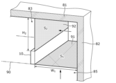
- FIG. 3 is a diagram showing a first example of a region formed within the room 80 in the airflow forming system according to the embodiment.
- FIG. 4 is a diagram schematically showing air recirculation in the airflow forming system shown in FIG. 3.
- FIG. 3 is a diagram showing a first example of a region formed within the room 80 in the airflow forming system according to the embodiment.
- FIG. 4 is a diagram schematically showing air recirculation in the airflow forming system shown in FIG. 3.
- the attraction space 84 is a space between two adjacent ducts 10 among the four ducts 10 installed in the room 80; A space 84 is formed.
- two reflux passage areas 91 are formed in the chamber 80.
- two reflux passage areas 91 are formed between the duct 10 and the wall 82 on the virtual plane 90 for each of the two ducts 10 that directly oppose the wall 82 among the four ducts 10. This is an area where
- the duct 10 that directly faces the wall 82 is a duct 10 that has a paired duct 10 on one side, does not have a paired duct 10 on the other side, and has the wall 82. .
- the air in the lower space 85 flows back into the upper space 83 through the space between the wall 82 and the duct 10 that directly faces the wall 82.
- a region on the virtual plane 90 of the space is a reflux passage region 91.
- the distance between adjacent ducts 10 in other words, , arrangement interval
- the distance between the duct 10 placed closest to the wall 82 in the direction in which the four ducts 10 are lined up and the wall 82 may be made larger.
- FIG. 4 For one of the two reflux passage areas 91 (on the positive side of the X axis) shown in FIG. An inflow surface 92 into 83 is shown.
- the vertical width H2 of the inflow surface 92 may be equal to or greater than the horizontal width W1 of the reflux passage area 91. This can reduce resistance when air in the lower space 85 flows into the upper space 83 between the plurality of ducts 10 and the ceiling 81, making it easier for the air to circulate.
- the relationship between the area S 1 of the reflux passage region 91 and the area S 2 of the inflow surface 92 is not particularly limited, but may be S 2 ⁇ S 1 .
- FIG. 5 is a diagram showing a second example of a region formed within the room 80 in the airflow forming system according to the embodiment.
- the air outlet 11 of the duct 10 located at the right end of the paper of the two ducts 10 directly facing the wall 82 is closed (in other words, the air outlet 11 is closed). 12), the space between the duct 10 (the duct 10 at the right end in the paper) and the duct 10 placed next to it (the second duct 10 from the right end in the paper) is also a path for air to return. include.
- the air outlet 11 of one of the adjacent ducts 10 among the plurality of ducts 10 is closed, the area on the virtual plane 90 of the space between the adjacent ducts 10 is also a reflux passage area. Included in 91. In the second example, three reflux passage areas 91 and two attraction spaces 84 are formed.
- the air outlet 11 may include a plurality of louvers along the air outlet 11. A part or all of the air outlet 11 may be closed by covering the air outlet 11 with a plurality of louvers.
- the present invention is not limited to this.
- the air outlet 11 of one of the ducts 10 (the middle two ducts of the four ducts 10 in FIG. 5) that have other ducts 10 arranged on both sides thereof may be closed.
- the space between the duct 10 and other ducts 10 located on both sides is also included in the air return path, so the room 80 has four return flow passage areas 91 and one attraction space 84. It is formed. In this way, when the air outlet 11 of any one of the four ducts 10 is closed, the total area of the attraction space 84 is equal to the area of the reflux passage area 91 in the top view of the room 80 seen from the ceiling 81. less than the sum.
- FIG. 6 is a diagram showing a third example of a region formed within the room 80 in the airflow forming system according to the embodiment.
- FIG. 7 is a diagram schematically showing air recirculation in the airflow forming system shown in FIG. 6.
- the outlet 11 of the duct 10 located at the right end of the paper is partially closed (in other words, When the air outlet 11 has a closed part 12), the duct 10 (the duct 10 on the right end of the paper) and the duct 10 placed next to it (the second duct 10 from the right end of the paper) Among the spaces between them, the space corresponding to the closed portion 12 is also included in the air circulation path. In this way, when a part of the air outlet 11 of one of the adjacent ducts 10 among the plurality of ducts 10 is closed, the air outlet 11 in the space between the adjacent ducts 10 is closed.
- the area on the virtual plane 90 of the space corresponding to the portion 12 is also included in the reflux passage area 91.
- FIG. 7A is a diagram schematically showing an example in which the recirculation air passing through the recirculation passage area 91 of the space A shown in FIG. 6 flows into the upper space 83 above the attraction spaces 84 of the plurality of ducts 10. be.
- the air in the lower space 85 flows through the space A in FIG.
- the water flows through the air and flows back into the upper space 83.
- FIG. 7B schematically shows an example in which the recirculation air passing through the recirculation passage area 91 of the space B shown in FIG. 6 flows into the space 83 above the plurality of ducts 10 adjacent to the recirculation passage area 91.
- FIG. 7(b) the air in the lower space 85 is a space on both sides of the duct 10 where the outlet 11 is partially closed. It flows back to the upper space 83 through two spaces (space B in FIG. 6) corresponding to the separated portion 12. Note that, in FIG. 7(b), only one duct 10 at the right end of the paper in FIG. 6 is illustrated.
- the portion 12 where the air outlet 11 is closed is increased so that the total area of the attraction space 84 is smaller than the total area of the reflux passage area 91 in a top view of the room 80 seen from the ceiling 81.
- the distance between the duct 10 disposed closest to the wall 82 in the direction in which the four ducts 10 are arranged and the wall 82 may be greater than the distance between adjacent ducts 10 (so-called arrangement interval).
- the vertical width H21 of the inflow surface 92 may be equal to or greater than the horizontal width W11 of the reflux passage area. This can reduce resistance when air in the lower space 85 flows into the upper space 83 between the plurality of ducts 10 and the ceiling 81, making it easier for the air to circulate.
- the relationship between the area S 11 of the reflux passage region 91 and the area S 21 of the inflow surface 92 is not particularly limited, but may be S 21 ⁇ S 11 .
- the vertical width H 22 of the inflow surface 92 may be equal to or greater than the width W 12 of the return flow passage area, and although not shown, the distance between adjacent ducts 10 (so-called , arrangement interval) or more. This can reduce resistance when air in the lower space 85 flows into the upper space 83 between the plurality of ducts 10 and the ceiling 81, making it easier for the air to circulate.
- the relationship between the area S 12 of the reflux passage region 91 and the area S 22 of the inflow surface 92 is not particularly limited, but may be S 22 ⁇ S 12 .
- the blower device 100 has a plurality of ducts 10 spaced apart from the ceiling 81 of the room 80 and installed in parallel on a virtual plane 90 parallel to the ceiling 81, and blows air out along the longitudinal direction of the plurality of ducts 10.
- a plurality of ducts 10 are spaced apart from a wall 82 and arranged in parallel on a virtual plane 90 parallel to the wall 82, and from the air outlet 11 along the longitudinal direction of the plurality of ducts 10 to the side of the room 80.
- Air may be blown out in a direction (for example, front, rear, left, and right directions).
- the blower device 100 attracts air into the space between the plurality of ducts 10 by blowing air out of the outlet 11 in an arbitrary direction depending on the installation state, and blows out the attracted air. It can be provided in the same arbitrary direction as the air blown out from the mouth 11.
- the airflow generation system may further include a second blower (not shown) that is installed in the lower space 85 and blows air from the lower space 85 to the upper space 83.
- the second blower may be a fan installed at a predetermined height from the floor surface, or may be a unit including a suction port for sucking air, a fan, and a filter.
- the airflow generation system can promote the circulation of air from the lower space 85 of the room 80 to the upper space 83 by the air blowing from the second blower, thereby providing a stable downflow in a closed space such as the room 80. be able to.
- the airflow forming system is an airflow forming system realized by the air blower 100 installed in the room 80, and the air blower 100 is a long airflow forming system that is spaced apart from the ceiling 81 and arranged in parallel.
- a plurality of ducts 10 , and a first blower 20 that blows air into the inside of each of the plurality of ducts 10
- each of the plurality of ducts 10 includes a plurality of ducts 10 on the side opposite to the ceiling 81 in the longitudinal direction of the duct 10 .
- a plurality of ducts 10 are arranged in a virtual plane 90 in which a plurality of ducts 10 are arranged in parallel.
- a recirculation passage region 91 is formed through which air flowing back from the lower space 85 to the upper space 83 between the plurality of ducts 10 and the ceiling 81 passes.
- Such an airflow forming system can return air to the space 83 above the plurality of ducts 10 in a closed space such as the room 80, and therefore can provide a stable downflow airflow.
- the reflux passage area 91 is It includes a region on the virtual surface 90 of the space corresponding to the air outlet 11 of part 12 of the space between.
- Such an airflow forming system allows return flow to pass between two adjacent ducts 10 by closing a part 12 of the outlet 11 of at least one of the two adjacent ducts 10 among the plurality of ducts 10. Region 91 can be formed. Therefore, the airflow forming system can adjust the return of air to the upper space 83 of the plurality of ducts 10 as necessary.
- the total area of the attraction space 84 which is a space between the plurality of ducts 10 and from which air is drawn from the upper space 83, is equal to the total area of the reflux passage area 91. less than the sum of the areas.
- Such an airflow generation system can circulate more of the air in the room 80 to the upper space 83. Therefore, the airflow generation system can provide a stable downflow airflow.
- the total area of the inflow surface 92 through which the air that has passed through the reflux passage area 91 flows into the upper space 83 of each of the plurality of ducts 10 is the sum of the area of the reflux passage area 91 in the top view of the room 80 seen from the ceiling 81. is greater than or equal to the sum of the areas of
- Such an airflow generation system can reduce the resistance when the air in the lower space 85 flows into the upper space 83 between the plurality of ducts 10 and the ceiling 81, so it can increase the amount of air in the room 80. It can be refluxed to the upper space 83. Therefore, the airflow generation system can provide a stable downflow airflow.
- the airflow forming system further includes a second blower (not shown) that is installed in the lower space 85 and blows air from the lower space 85 to the upper space 83.
- a second blower (not shown) that is installed in the lower space 85 and blows air from the lower space 85 to the upper space 83.
- Such an airflow generation system can circulate the air in the room 80 from the lower space 85 to the upper space 83 using the second blower. Therefore, the airflow generation system can provide a stable downflow airflow.
- the blower device 100 includes an even number of elongated ducts 10 arranged in parallel, but the present invention is not limited to this example.
- the blower device 100 may include an odd number (for example, three or more) of elongated ducts 10 arranged in parallel.
- the blower device 100 is provided with one air outlet 11 along the longitudinal direction of the duct 10, but a plurality of air outlets are provided along the longitudinal direction of the duct 10. It's okay to be hit.
- a louver may be attached to each of the plurality of air outlets.
- air is discharged from the outlet 11 in a predetermined direction (for example, from the upper space 83 to the lower space 85), but the air may be discharged in a desired direction by a louver. This makes it possible to generate a downflow in a desired direction.
- the general or specific aspects of the present invention may be implemented in a system, device, method, integrated circuit, computer program, or computer-readable recording medium such as a CD-ROM.
- the present invention may be realized by any combination of a system, an apparatus, a method, an integrated circuit, a computer program, and a recording medium.
- the present invention may be realized as a building to which the airflow control system of the above embodiment is applied.
- the present invention may be implemented as a control method for a blower device executed by a computer such as the control unit of the above embodiment, or may be implemented as a program for causing a computer to execute such a control method. good.
- the present invention may be realized as a computer-readable non-transitory recording medium on which such a program is recorded.
Abstract
Ce système de formation d'écoulement d'air est réalisé par un dispositif de ventilation (100) installé dans une pièce (80). Le dispositif de ventilation (100) comprend : une pluralité de conduits allongés (10) disposés côte à côte et espacés d'un plafond (81) ; et un premier ventilateur (20) qui effectue une ventilation de l'intérieur de chaque conduit de la pluralité de conduits (10). Chaque conduit de la pluralité de conduits (10) est pourvu d'une sortie d'air allongée qui suit une direction longitudinale des conduits (10) sur un côté opposé au plafond (81) et à travers laquelle de l'air est soufflé par ventilation. Dans la pièce (80), une zone de passage de recirculation à travers laquelle de l'air passe est formée sur un plan virtuel sur lequel la pluralité de conduits (10) sont agencés côte à côte, l'air étant remis en circulation depuis un espace inférieur (85) de la pluralité de conduits (10) vers un espace supérieur (83) entre la pluralité de conduits (10) et le plafond (81).
Applications Claiming Priority (2)
| Application Number | Priority Date | Filing Date | Title |
|---|---|---|---|
| JP2022-045204 | 2022-03-22 | ||
| JP2022045204 | 2022-03-22 |
Publications (1)
| Publication Number | Publication Date |
|---|---|
| WO2023181535A1 true WO2023181535A1 (fr) | 2023-09-28 |
Family
ID=88100865
Family Applications (1)
| Application Number | Title | Priority Date | Filing Date |
|---|---|---|---|
| PCT/JP2022/046644 WO2023181535A1 (fr) | 2022-03-22 | 2022-12-19 | Système de formation d'écoulement d'air |
Country Status (1)
| Country | Link |
|---|---|
| WO (1) | WO2023181535A1 (fr) |
Citations (2)
| Publication number | Priority date | Publication date | Assignee | Title |
|---|---|---|---|---|
| JP2017160787A (ja) * | 2016-03-07 | 2017-09-14 | パナソニックIpマネジメント株式会社 | 送風装置 |
| JP2019148171A (ja) * | 2018-02-26 | 2019-09-05 | パナソニックIpマネジメント株式会社 | 送風装置 |
-
2022
- 2022-12-19 WO PCT/JP2022/046644 patent/WO2023181535A1/fr unknown
Patent Citations (2)
| Publication number | Priority date | Publication date | Assignee | Title |
|---|---|---|---|---|
| JP2017160787A (ja) * | 2016-03-07 | 2017-09-14 | パナソニックIpマネジメント株式会社 | 送風装置 |
| JP2019148171A (ja) * | 2018-02-26 | 2019-09-05 | パナソニックIpマネジメント株式会社 | 送風装置 |
Similar Documents
| Publication | Publication Date | Title |
|---|---|---|
| JP6650562B2 (ja) | 送風装置および送風機能付空気清浄装置 | |
| JP6603874B2 (ja) | 送風装置および送風機能付空気清浄装置 | |
| JPWO2009054316A1 (ja) | 天井埋込型の空気調和機 | |
| KR100590329B1 (ko) | 환기장치 | |
| JP2007024345A (ja) | 空気調和機 | |
| TWI395872B (zh) | At the same time supply row ventilation fans and air conditioning devices | |
| US20050287945A1 (en) | Ventilating system | |
| JP6348689B2 (ja) | 送風装置及び空調システム | |
| JP6767616B2 (ja) | 送風装置 | |
| JP2007255848A (ja) | 空気調和機及びこれを用いた空気調和システム | |
| JP4779554B2 (ja) | ダクトファン | |
| JP6139669B2 (ja) | 空気調和機 | |
| WO2023181535A1 (fr) | Système de formation d'écoulement d'air | |
| JPS62178836A (ja) | 空気調和機 | |
| JP2005024225A (ja) | 空気調和機 | |
| JP7065298B2 (ja) | 熱交換形換気装置 | |
| JP6064162B2 (ja) | 空気清浄装置 | |
| JP2022167258A (ja) | 空気浄化ユニット | |
| JP2008185235A (ja) | 床置形空気調和機 | |
| JP7281625B2 (ja) | 換気グリル | |
| WO2021024714A1 (fr) | Dispositif de soufflante | |
| JP3098954B2 (ja) | 熱気を含んだ内気の排出装置 | |
| WO2023228502A1 (fr) | Dispositif de ventilateur soufflant | |
| JP7249485B2 (ja) | 熱交換形換気装置 | |
| WO2023002531A1 (fr) | Appareil de chauffage |
Legal Events
| Date | Code | Title | Description |
|---|---|---|---|
| 121 | Ep: the epo has been informed by wipo that ep was designated in this application |
Ref document number: 22933663 Country of ref document: EP Kind code of ref document: A1 |