WO2023181535A1 - Airflow formation system - Google Patents
Airflow formation system Download PDFInfo
- Publication number
- WO2023181535A1 WO2023181535A1 PCT/JP2022/046644 JP2022046644W WO2023181535A1 WO 2023181535 A1 WO2023181535 A1 WO 2023181535A1 JP 2022046644 W JP2022046644 W JP 2022046644W WO 2023181535 A1 WO2023181535 A1 WO 2023181535A1
- Authority
- WO
- WIPO (PCT)
- Prior art keywords
- ducts
- air
- space
- room
- ceiling
- Prior art date
Links
- 230000015572 biosynthetic process Effects 0.000 title claims abstract 4
- 238000010992 reflux Methods 0.000 claims description 26
- 238000007664 blowing Methods 0.000 claims description 4
- 238000009423 ventilation Methods 0.000 abstract description 5
- 238000010586 diagram Methods 0.000 description 16
- 230000004048 modification Effects 0.000 description 7
- 238000012986 modification Methods 0.000 description 7
- 238000000034 method Methods 0.000 description 4
- 239000000470 constituent Substances 0.000 description 3
- 239000000463 material Substances 0.000 description 3
- 229910052782 aluminium Inorganic materials 0.000 description 2
- XAGFODPZIPBFFR-UHFFFAOYSA-N aluminium Chemical compound [Al] XAGFODPZIPBFFR-UHFFFAOYSA-N 0.000 description 2
- 238000004590 computer program Methods 0.000 description 2
- 239000007769 metal material Substances 0.000 description 2
- 239000011347 resin Substances 0.000 description 2
- 229920005989 resin Polymers 0.000 description 2
- 238000009434 installation Methods 0.000 description 1
- XLYOFNOQVPJJNP-UHFFFAOYSA-N water Substances O XLYOFNOQVPJJNP-UHFFFAOYSA-N 0.000 description 1
Images


Classifications
-
- F—MECHANICAL ENGINEERING; LIGHTING; HEATING; WEAPONS; BLASTING
- F24—HEATING; RANGES; VENTILATING
- F24F—AIR-CONDITIONING; AIR-HUMIDIFICATION; VENTILATION; USE OF AIR CURRENTS FOR SCREENING
- F24F13/00—Details common to, or for air-conditioning, air-humidification, ventilation or use of air currents for screening
- F24F13/02—Ducting arrangements
- F24F13/06—Outlets for directing or distributing air into rooms or spaces, e.g. ceiling air diffuser
- F24F13/072—Outlets for directing or distributing air into rooms or spaces, e.g. ceiling air diffuser of elongated shape, e.g. between ceiling panels
-
- F—MECHANICAL ENGINEERING; LIGHTING; HEATING; WEAPONS; BLASTING
- F24—HEATING; RANGES; VENTILATING
- F24F—AIR-CONDITIONING; AIR-HUMIDIFICATION; VENTILATION; USE OF AIR CURRENTS FOR SCREENING
- F24F7/00—Ventilation
- F24F7/04—Ventilation with ducting systems, e.g. by double walls; with natural circulation
- F24F7/06—Ventilation with ducting systems, e.g. by double walls; with natural circulation with forced air circulation, e.g. by fan positioning of a ventilator in or against a conduit
Definitions
- the present invention relates to an airflow forming system.
- Patent Document 1 discloses that the air blower is attached to the ceiling surface and utilizes the swirling jet flow generated from the fan of the blower to sufficiently lengthen the reach of the downward flow in the axial direction from the outlet just below the ceiling to the floor surface.
- a recirculation device that quickly and reliably recirculates indoor air is disclosed.
- the recirculation device described in Patent Document 1 sucks indoor air that remains near the ceiling surface and discharges the sucked air into the room, but if sufficient recirculation air is not supplied near the ceiling surface, the air flow inside the room may not be able to be discharged stably.
- the present invention provides an airflow forming system that can provide a stable downflow airflow (hereinafter also referred to as downflow) in a closed space such as a room (also referred to as closed space).
- a stable downflow airflow hereinafter also referred to as downflow
- a closed space such as a room (also referred to as closed space).
- An air blower is an airflow forming system realized by an air blower installed in a room, and the air blower includes a plurality of elongated air blowers arranged in parallel and spaced apart from the ceiling. a duct, and a first blower that blows air into each of the plurality of ducts, and each of the plurality of ducts has an elongated air outlet along the longitudinal direction of the duct on the opposite side from the ceiling.
- a vent is provided from which air is blown out by the blowing air, and the room has air flowing back from the lower space to the upper space in a virtual plane in which the plurality of ducts are arranged in parallel.
- a reflux passage region is formed through which the reflux passes.
- the airflow forming system can provide a stable downflow airflow in a closed space such as a room.
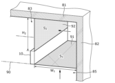
- FIG. 1 is a diagram for explaining an overview of an airflow forming system according to an embodiment.
- FIG. 2 is a diagram for explaining the configuration of the air blower in the embodiment.
- FIG. 3 is a diagram showing a first example of a region formed in a room in the airflow forming system according to the embodiment.
- FIG. 4 is a diagram schematically showing air recirculation in the airflow forming system shown in FIG. 3.
- FIG. FIG. 5 is a diagram showing a second example of a region formed in a room in the airflow forming system according to the embodiment.
- FIG. 6 is a diagram showing a third example of a region formed in a room in the airflow forming system according to the embodiment.
- FIG. 7 is a diagram schematically showing air recirculation in the airflow forming system shown in FIG. 6.
- each figure is a schematic diagram and is not necessarily strictly illustrated. Further, in each figure, substantially the same configurations are denoted by the same reference numerals, and overlapping explanations may be omitted or simplified.
- FIG. 1 is a diagram for explaining an overview of an airflow forming system according to an embodiment.
- FIG. 2 is a diagram for explaining the configuration of the air blower in the embodiment.
- the airflow generation system according to the embodiment is an airflow generation system realized by a blower device 100 installed in a room 80.
- a blower device 100 installed in a room 80.
- a closed space such as the room 80 surrounded by walls and a ceiling
- the return flow of air from the lower space 85 to the upper space 83 tends to become stagnant, making it difficult to provide a stable downflow. Therefore, in the airflow generation system according to the present embodiment, in a closed space such as the room 80, a path for air circulation is secured so that the air in the room 80 can easily circulate from the lower space to the upper space.
- the air blower 100 includes a plurality of ducts 10 arranged in parallel and spaced apart from the ceiling 81, and a first air blower 20 that blows air into each of the plurality of ducts 10.
- Each of the plurality of ducts 10 is provided with an elongated air outlet 11 along the longitudinal direction of the duct 10 on the side opposite to the ceiling 81.
- each air outlet 11 of the plurality of ducts 10 blows out air blown by the first blower 20.
- FIG. 2 As a result, for example, as shown in the cross-sectional view taken along the II-II cross-sectional line in FIG.
- Attracted air currents (white arrows in the figure) are generated that are attracted to the respective spaces and move toward the spaces below the plurality of ducts 10 (in other words, the lower spaces 85).
- This space is called an attraction space 84.
- the blower device 100 blows air out of the air outlet 11 of each of the plurality of ducts 10, thereby generating surface air (referred to as downflow) formed by the blown air (blowout airflow) and the induced airflow.
- the attraction space 84 is in a state where the atmospheric pressure is lower than the surroundings (negative pressure state)
- a force acts to eliminate the low atmospheric pressure state.
- the air around the plurality of ducts 10 here, the air existing in the upper space 83
- the induced space 84 becomes a negative pressure state is because air is blown out from the air outlets 11 provided in the plurality of ducts 10, and the air in the space around the blown air (airflow) is turned into the airflow. This is because you are drawn to it.
- the specific configuration of the first blower 20 will be described later.
- the air in the room 80 is easily returned from the lower space 85 to the upper space 83.
- a path for the air to circulate it becomes possible to generate a stable downflow in the blower device 100 installed in the room 80.
- the blower device 100 includes a plurality of ducts 10 and a first blower 20.
- Each of the plurality of ducts 10 has an elongated shape whose longitudinal direction is in the Y-axis direction.
- the plurality of ducts 10 are arranged in parallel in the X-axis direction that intersects the Y-axis direction. That is, the plurality of ducts 10 are arranged in parallel.
- a gap is provided between the plurality of ducts 10.
- the plurality of ducts 10 are arranged on one XY plane.
- the duct 10 has a hollow rectangular parallelepiped shape.
- the top surface (Z-axis negative side surface) and two side surfaces (X-axis positive side and negative side) of the duct 10 are closed. That is, no opening is provided on the top surface and two side surfaces of the duct 10.
- the duct 10 is made of, for example, a resin material, but may also be made of a lightweight metal material such as aluminum.
- An air outlet 11 is provided on the lower surface (Z-axis positive side surface) of the duct 10.
- the air outlet 11 is an elongated opening along the longitudinal direction (Y-axis direction) of the duct 10, and when the first blower 20 blows air into the duct 10, the air outlet 11 opens downward (Z-axis direction). Air is blown out in the positive direction of the shaft.
- the width (length in the X-axis direction) of the air outlet 11 becomes narrower as it goes downward, as shown in the cross-sectional view taken along the line II-II in FIG. 2, for example.
- the width of the air outlet 11 becomes exponentially narrower as it goes downward.
- the duct 10 is not provided with an opening on the front (Y-axis positive side), but has a ventilation hole ( (not shown in FIGS. 1 and 2) is provided.
- the vent is connected to the inside of the casing of the first blower 20, and the first blower 20 blows air into each of the plurality of ducts 10 through the vent.
- the flow of air caused by the first blower 20 is indicated by the dashed arrow in FIG. 2 .
- the first blower 20 is located at one end of the plurality of ducts 10 in the longitudinal direction (the end on the negative side of the Y-axis), and blows air into the inside of each of the plurality of ducts 10.
- the first blower 20 is installed, for example, in the interior space of the wall 82 of the room 80.
- the first blower 20 sucks air blown into the lower space 85 by the blower 100 from an opening provided in the lower part of the wall 82, and sends it upward.
- the first blower 20 includes a fan 21, piping 22, and a filter unit 23.
- the fan 21 includes an impeller (not shown) for generating high-pressure air and a motor (not shown) that drives the impeller.
- the filter unit 23 includes, for example, a HEPA (High Efficiency Particulate Air) filter.
- the front surface (Y-axis positive side surface) of the filter unit 23 is provided with an air outlet (not shown) that communicates with the air vents (not shown) on the back side of each of the plurality of ducts 10 .
- An opening (not shown) is provided below the filter unit 23 (on the Z-axis positive side) and is connected to the pipe 22.
- the housing of the filter unit 23 is made of, for example, a resin material, but may also be made of a lightweight metal material such as aluminum. Note that the arrangement of the fan 21 is an example. The fan 21 may be arranged in any manner as long as it can send air into each of the plurality of ducts 10.
- the air blower 100 is configured to The air in the space 83 above the plurality of ducts 10 is drawn (in other words, attracted) to each space (so-called attraction space 84) between two matching ducts 10.
- an induced airflow (indicated by the white wiping arrow in FIG. 2) from each of the induced spaces 84 between two adjacent ducts 10 of the plurality of ducts 10 toward the lower space 85 is generated.
- a downflow is generated by a blowout airflow blown out from the outlet 11 of the duct 10 toward the lower space 85 and an induced airflow directed from the attraction space 84 between the plurality of ducts 10 toward the lower space 85. be able to.
- a reflux passage area 91 through which air flowing back from the lower space 85 to the upper space 83 passes is formed in a virtual plane 90 (see FIG. 4) where a plurality of ducts 10 are arranged in parallel.
- the total area of the attraction space 84 must be is preferably smaller than the total area of the reflux passage region 91.
- the area of the attraction space 84 when viewed from above is the area of the area on the virtual plane 90 of the attraction space 84 (hereinafter referred to as attraction area).
- FIG. 3 is a diagram showing a first example of a region formed within the room 80 in the airflow forming system according to the embodiment.
- FIG. 4 is a diagram schematically showing air recirculation in the airflow forming system shown in FIG. 3.
- FIG. 3 is a diagram showing a first example of a region formed within the room 80 in the airflow forming system according to the embodiment.
- FIG. 4 is a diagram schematically showing air recirculation in the airflow forming system shown in FIG. 3.
- the attraction space 84 is a space between two adjacent ducts 10 among the four ducts 10 installed in the room 80; A space 84 is formed.
- two reflux passage areas 91 are formed in the chamber 80.
- two reflux passage areas 91 are formed between the duct 10 and the wall 82 on the virtual plane 90 for each of the two ducts 10 that directly oppose the wall 82 among the four ducts 10. This is an area where
- the duct 10 that directly faces the wall 82 is a duct 10 that has a paired duct 10 on one side, does not have a paired duct 10 on the other side, and has the wall 82. .
- the air in the lower space 85 flows back into the upper space 83 through the space between the wall 82 and the duct 10 that directly faces the wall 82.
- a region on the virtual plane 90 of the space is a reflux passage region 91.
- the distance between adjacent ducts 10 in other words, , arrangement interval
- the distance between the duct 10 placed closest to the wall 82 in the direction in which the four ducts 10 are lined up and the wall 82 may be made larger.
- FIG. 4 For one of the two reflux passage areas 91 (on the positive side of the X axis) shown in FIG. An inflow surface 92 into 83 is shown.
- the vertical width H2 of the inflow surface 92 may be equal to or greater than the horizontal width W1 of the reflux passage area 91. This can reduce resistance when air in the lower space 85 flows into the upper space 83 between the plurality of ducts 10 and the ceiling 81, making it easier for the air to circulate.
- the relationship between the area S 1 of the reflux passage region 91 and the area S 2 of the inflow surface 92 is not particularly limited, but may be S 2 ⁇ S 1 .
- FIG. 5 is a diagram showing a second example of a region formed within the room 80 in the airflow forming system according to the embodiment.
- the air outlet 11 of the duct 10 located at the right end of the paper of the two ducts 10 directly facing the wall 82 is closed (in other words, the air outlet 11 is closed). 12), the space between the duct 10 (the duct 10 at the right end in the paper) and the duct 10 placed next to it (the second duct 10 from the right end in the paper) is also a path for air to return. include.
- the air outlet 11 of one of the adjacent ducts 10 among the plurality of ducts 10 is closed, the area on the virtual plane 90 of the space between the adjacent ducts 10 is also a reflux passage area. Included in 91. In the second example, three reflux passage areas 91 and two attraction spaces 84 are formed.
- the air outlet 11 may include a plurality of louvers along the air outlet 11. A part or all of the air outlet 11 may be closed by covering the air outlet 11 with a plurality of louvers.
- the present invention is not limited to this.
- the air outlet 11 of one of the ducts 10 (the middle two ducts of the four ducts 10 in FIG. 5) that have other ducts 10 arranged on both sides thereof may be closed.
- the space between the duct 10 and other ducts 10 located on both sides is also included in the air return path, so the room 80 has four return flow passage areas 91 and one attraction space 84. It is formed. In this way, when the air outlet 11 of any one of the four ducts 10 is closed, the total area of the attraction space 84 is equal to the area of the reflux passage area 91 in the top view of the room 80 seen from the ceiling 81. less than the sum.
- FIG. 6 is a diagram showing a third example of a region formed within the room 80 in the airflow forming system according to the embodiment.
- FIG. 7 is a diagram schematically showing air recirculation in the airflow forming system shown in FIG. 6.
- the outlet 11 of the duct 10 located at the right end of the paper is partially closed (in other words, When the air outlet 11 has a closed part 12), the duct 10 (the duct 10 on the right end of the paper) and the duct 10 placed next to it (the second duct 10 from the right end of the paper) Among the spaces between them, the space corresponding to the closed portion 12 is also included in the air circulation path. In this way, when a part of the air outlet 11 of one of the adjacent ducts 10 among the plurality of ducts 10 is closed, the air outlet 11 in the space between the adjacent ducts 10 is closed.
- the area on the virtual plane 90 of the space corresponding to the portion 12 is also included in the reflux passage area 91.
- FIG. 7A is a diagram schematically showing an example in which the recirculation air passing through the recirculation passage area 91 of the space A shown in FIG. 6 flows into the upper space 83 above the attraction spaces 84 of the plurality of ducts 10. be.
- the air in the lower space 85 flows through the space A in FIG.
- the water flows through the air and flows back into the upper space 83.
- FIG. 7B schematically shows an example in which the recirculation air passing through the recirculation passage area 91 of the space B shown in FIG. 6 flows into the space 83 above the plurality of ducts 10 adjacent to the recirculation passage area 91.
- FIG. 7(b) the air in the lower space 85 is a space on both sides of the duct 10 where the outlet 11 is partially closed. It flows back to the upper space 83 through two spaces (space B in FIG. 6) corresponding to the separated portion 12. Note that, in FIG. 7(b), only one duct 10 at the right end of the paper in FIG. 6 is illustrated.
- the portion 12 where the air outlet 11 is closed is increased so that the total area of the attraction space 84 is smaller than the total area of the reflux passage area 91 in a top view of the room 80 seen from the ceiling 81.
- the distance between the duct 10 disposed closest to the wall 82 in the direction in which the four ducts 10 are arranged and the wall 82 may be greater than the distance between adjacent ducts 10 (so-called arrangement interval).
- the vertical width H21 of the inflow surface 92 may be equal to or greater than the horizontal width W11 of the reflux passage area. This can reduce resistance when air in the lower space 85 flows into the upper space 83 between the plurality of ducts 10 and the ceiling 81, making it easier for the air to circulate.
- the relationship between the area S 11 of the reflux passage region 91 and the area S 21 of the inflow surface 92 is not particularly limited, but may be S 21 ⁇ S 11 .
- the vertical width H 22 of the inflow surface 92 may be equal to or greater than the width W 12 of the return flow passage area, and although not shown, the distance between adjacent ducts 10 (so-called , arrangement interval) or more. This can reduce resistance when air in the lower space 85 flows into the upper space 83 between the plurality of ducts 10 and the ceiling 81, making it easier for the air to circulate.
- the relationship between the area S 12 of the reflux passage region 91 and the area S 22 of the inflow surface 92 is not particularly limited, but may be S 22 ⁇ S 12 .
- the blower device 100 has a plurality of ducts 10 spaced apart from the ceiling 81 of the room 80 and installed in parallel on a virtual plane 90 parallel to the ceiling 81, and blows air out along the longitudinal direction of the plurality of ducts 10.
- a plurality of ducts 10 are spaced apart from a wall 82 and arranged in parallel on a virtual plane 90 parallel to the wall 82, and from the air outlet 11 along the longitudinal direction of the plurality of ducts 10 to the side of the room 80.
- Air may be blown out in a direction (for example, front, rear, left, and right directions).
- the blower device 100 attracts air into the space between the plurality of ducts 10 by blowing air out of the outlet 11 in an arbitrary direction depending on the installation state, and blows out the attracted air. It can be provided in the same arbitrary direction as the air blown out from the mouth 11.
- the airflow generation system may further include a second blower (not shown) that is installed in the lower space 85 and blows air from the lower space 85 to the upper space 83.
- the second blower may be a fan installed at a predetermined height from the floor surface, or may be a unit including a suction port for sucking air, a fan, and a filter.
- the airflow generation system can promote the circulation of air from the lower space 85 of the room 80 to the upper space 83 by the air blowing from the second blower, thereby providing a stable downflow in a closed space such as the room 80. be able to.
- the airflow forming system is an airflow forming system realized by the air blower 100 installed in the room 80, and the air blower 100 is a long airflow forming system that is spaced apart from the ceiling 81 and arranged in parallel.
- a plurality of ducts 10 , and a first blower 20 that blows air into the inside of each of the plurality of ducts 10
- each of the plurality of ducts 10 includes a plurality of ducts 10 on the side opposite to the ceiling 81 in the longitudinal direction of the duct 10 .
- a plurality of ducts 10 are arranged in a virtual plane 90 in which a plurality of ducts 10 are arranged in parallel.
- a recirculation passage region 91 is formed through which air flowing back from the lower space 85 to the upper space 83 between the plurality of ducts 10 and the ceiling 81 passes.
- Such an airflow forming system can return air to the space 83 above the plurality of ducts 10 in a closed space such as the room 80, and therefore can provide a stable downflow airflow.
- the reflux passage area 91 is It includes a region on the virtual surface 90 of the space corresponding to the air outlet 11 of part 12 of the space between.
- Such an airflow forming system allows return flow to pass between two adjacent ducts 10 by closing a part 12 of the outlet 11 of at least one of the two adjacent ducts 10 among the plurality of ducts 10. Region 91 can be formed. Therefore, the airflow forming system can adjust the return of air to the upper space 83 of the plurality of ducts 10 as necessary.
- the total area of the attraction space 84 which is a space between the plurality of ducts 10 and from which air is drawn from the upper space 83, is equal to the total area of the reflux passage area 91. less than the sum of the areas.
- Such an airflow generation system can circulate more of the air in the room 80 to the upper space 83. Therefore, the airflow generation system can provide a stable downflow airflow.
- the total area of the inflow surface 92 through which the air that has passed through the reflux passage area 91 flows into the upper space 83 of each of the plurality of ducts 10 is the sum of the area of the reflux passage area 91 in the top view of the room 80 seen from the ceiling 81. is greater than or equal to the sum of the areas of
- Such an airflow generation system can reduce the resistance when the air in the lower space 85 flows into the upper space 83 between the plurality of ducts 10 and the ceiling 81, so it can increase the amount of air in the room 80. It can be refluxed to the upper space 83. Therefore, the airflow generation system can provide a stable downflow airflow.
- the airflow forming system further includes a second blower (not shown) that is installed in the lower space 85 and blows air from the lower space 85 to the upper space 83.
- a second blower (not shown) that is installed in the lower space 85 and blows air from the lower space 85 to the upper space 83.
- Such an airflow generation system can circulate the air in the room 80 from the lower space 85 to the upper space 83 using the second blower. Therefore, the airflow generation system can provide a stable downflow airflow.
- the blower device 100 includes an even number of elongated ducts 10 arranged in parallel, but the present invention is not limited to this example.
- the blower device 100 may include an odd number (for example, three or more) of elongated ducts 10 arranged in parallel.
- the blower device 100 is provided with one air outlet 11 along the longitudinal direction of the duct 10, but a plurality of air outlets are provided along the longitudinal direction of the duct 10. It's okay to be hit.
- a louver may be attached to each of the plurality of air outlets.
- air is discharged from the outlet 11 in a predetermined direction (for example, from the upper space 83 to the lower space 85), but the air may be discharged in a desired direction by a louver. This makes it possible to generate a downflow in a desired direction.
- the general or specific aspects of the present invention may be implemented in a system, device, method, integrated circuit, computer program, or computer-readable recording medium such as a CD-ROM.
- the present invention may be realized by any combination of a system, an apparatus, a method, an integrated circuit, a computer program, and a recording medium.
- the present invention may be realized as a building to which the airflow control system of the above embodiment is applied.
- the present invention may be implemented as a control method for a blower device executed by a computer such as the control unit of the above embodiment, or may be implemented as a program for causing a computer to execute such a control method. good.
- the present invention may be realized as a computer-readable non-transitory recording medium on which such a program is recorded.
Abstract
This airflow formation system is realized by a ventilation device (100) installed in a room (80). The ventilation device (100) comprises: a plurality of elongated ducts (10) arranged side by side and spaced apart from a ceiling (81); and a first ventilator (20) that performs ventilation of the interior of each of the plurality of ducts (10). Each of the plurality of ducts (10) is provided with an elongated air outlet which follows a longitudinal direction of the ducts (10) on a side opposite to the ceiling (81) and through which air is blown out by ventilation. In the room (80), a recirculation passage area through which air passes is formed on a virtual plane whereon the plurality of ducts (10) are arranged side by side, the air being recirculated from a lower space (85) of the plurality of ducts (10) to an upper space (83) between the plurality of ducts (10) and the ceiling (81).
Description
本発明は、気流形成システムに関する。
The present invention relates to an airflow forming system.
特許文献1には、天井面に取り付けられ、送風機のファンから生じる旋回噴流を利用して天井直下の吐き出し口から床面までの下降流の軸方向への到達距離を十分に長くすることで、室内空気の還流を迅速かつ確実に行う還流装置が開示されている。
Patent Document 1 discloses that the air blower is attached to the ceiling surface and utilizes the swirling jet flow generated from the fan of the blower to sufficiently lengthen the reach of the downward flow in the axial direction from the outlet just below the ceiling to the floor surface. A recirculation device that quickly and reliably recirculates indoor air is disclosed.
しかしながら、特許文献1に記載の還流装置は、天井面付近に滞留する室内空気を吸い込み、吸い込んだ空気を室内に吐出するが、天井面付近に十分な還流空気が供給されない場合、室内に空気流を安定的に吐出できなくなる可能性がある。
However, the recirculation device described in Patent Document 1 sucks indoor air that remains near the ceiling surface and discharges the sucked air into the room, but if sufficient recirculation air is not supplied near the ceiling surface, the air flow inside the room may not be able to be discharged stably.
本発明は、部屋などの閉鎖的な空間(閉空間ともいう)において安定したダウンフロー気流(以下、ダウンフローともいう)を提供することができる気流形成システムを提供する。
The present invention provides an airflow forming system that can provide a stable downflow airflow (hereinafter also referred to as downflow) in a closed space such as a room (also referred to as closed space).
本発明の一態様に係る送風装置は、部屋に設置された送風装置によって実現される気流形成システムであって、前記送風装置は、天井から離間して並列に配置された長尺状の複数のダクトと、前記複数のダクトのそれぞれの内部へ送風を行う第一送風機と、を備え、前記複数のダクトのそれぞれには、前記天井と反対側に当該ダクトの長手方向に沿う長尺状の吹き出し口であって、前記送風により空気が吹き出される吹き出し口が設けられ、前記部屋には、前記複数のダクトが並列に配置される仮想面において、前記下方空間から前記上方空間へ還流する空気が通過する還流通過領域が形成される。
An air blower according to one aspect of the present invention is an airflow forming system realized by an air blower installed in a room, and the air blower includes a plurality of elongated air blowers arranged in parallel and spaced apart from the ceiling. a duct, and a first blower that blows air into each of the plurality of ducts, and each of the plurality of ducts has an elongated air outlet along the longitudinal direction of the duct on the opposite side from the ceiling. A vent is provided from which air is blown out by the blowing air, and the room has air flowing back from the lower space to the upper space in a virtual plane in which the plurality of ducts are arranged in parallel. A reflux passage region is formed through which the reflux passes.
本発明の一態様に係る気流形成システムは、部屋などの閉鎖的な空間において安定したダウンフロー気流を提供することができる。
The airflow forming system according to one aspect of the present invention can provide a stable downflow airflow in a closed space such as a room.
以下、実施の形態について、図面を参照しながら具体的に説明する。なお、以下で説明する実施の形態は、いずれも包括的又は具体的な例を示すものである。以下の実施の形態で示される数値、形状、材料、構成要素、構成要素の配置位置及び接続形態、ステップ、ステップの順序などは、一例であり、本発明を限定する主旨ではない。また、以下の実施の形態における構成要素のうち、独立請求項に記載されていない構成要素については、任意の構成要素として説明される。
Hereinafter, embodiments will be specifically described with reference to the drawings. Note that the embodiments described below are all inclusive or specific examples. The numerical values, shapes, materials, components, arrangement positions and connection forms of the components, steps, order of steps, etc. shown in the following embodiments are merely examples, and do not limit the present invention. Further, among the constituent elements in the following embodiments, constituent elements that are not described in the independent claims will be described as arbitrary constituent elements.
なお、各図は模式図であり、必ずしも厳密に図示されたものではない。また、各図において、実質的に同一の構成に対しては同一の符号を付し、重複する説明は省略又は簡略化される場合がある。
Note that each figure is a schematic diagram and is not necessarily strictly illustrated. Further, in each figure, substantially the same configurations are denoted by the same reference numerals, and overlapping explanations may be omitted or simplified.
(実施の形態)
[概要]
まず、実施の形態に係る気流形成システムの概要について説明する。図1は、実施の形態に係る気流形成システムの概要を説明するための図である。図2は、実施の形態における送風装置の構成を説明するための図である。 (Embodiment)
[overview]
First, an overview of the airflow forming system according to the embodiment will be explained. FIG. 1 is a diagram for explaining an overview of an airflow forming system according to an embodiment. FIG. 2 is a diagram for explaining the configuration of the air blower in the embodiment.
実施の形態に係る気流形成システムは、部屋80に設置された送風装置100によって実現される気流発生システムである。従来、部屋80などの壁及び天井で囲まれた閉空間では、下方空間85から上方空間83への空気の還流が滞りやすくなり、安定したダウンフローを提供することが難しい。そのため、本実施の形態に係る気流発生システムでは、部屋80などの閉空間において、部屋80内の空気が下方空間から上方空間へ還流しやすくなるように、空気が還流する経路を確保する。
The airflow generation system according to the embodiment is an airflow generation system realized by a blower device 100 installed in a room 80. Conventionally, in a closed space such as the room 80 surrounded by walls and a ceiling, the return flow of air from the lower space 85 to the upper space 83 tends to become stagnant, making it difficult to provide a stable downflow. Therefore, in the airflow generation system according to the present embodiment, in a closed space such as the room 80, a path for air circulation is secured so that the air in the room 80 can easily circulate from the lower space to the upper space.
送風装置100は、天井81と離間して並列に配置された複数のダクト10と、複数のダクト10のそれぞれの内部へ送風を行う第一送風機20とを備える。複数のダクト10は、それぞれ、天井81と反対側にダクト10の長手方向に沿う長尺状の吹き出し口11を備えている。例えば、図2に示されるように、複数のダクト10のそれぞれの吹き出し口11は、第一送風機20によって送風された空気を吹き出す。これにより、例えば、図2のII-II断面線で切断された断面図に示されるように、複数のダクト10と天井81との間の上方空間83に存在する空気が複数のダクト10の間のそれぞれの空間に誘引され、複数のダクト10の下方の空間(言い換えると、下方空間85)へと向かう誘引気流(図中の白抜き矢印)が発生する。この空間を誘引空間84と呼ぶ。送風装置100は、複数のダクト10のそれぞれの吹き出し口11から空気を吹き出すことにより、吹き出された空気(吹出気流)と誘引気流とで形成される面空気(ダウンフローという)を発生させる。
The air blower 100 includes a plurality of ducts 10 arranged in parallel and spaced apart from the ceiling 81, and a first air blower 20 that blows air into each of the plurality of ducts 10. Each of the plurality of ducts 10 is provided with an elongated air outlet 11 along the longitudinal direction of the duct 10 on the side opposite to the ceiling 81. For example, as shown in FIG. 2, each air outlet 11 of the plurality of ducts 10 blows out air blown by the first blower 20. As a result, for example, as shown in the cross-sectional view taken along the II-II cross-sectional line in FIG. Attracted air currents (white arrows in the figure) are generated that are attracted to the respective spaces and move toward the spaces below the plurality of ducts 10 (in other words, the lower spaces 85). This space is called an attraction space 84. The blower device 100 blows air out of the air outlet 11 of each of the plurality of ducts 10, thereby generating surface air (referred to as downflow) formed by the blown air (blowout airflow) and the induced airflow.
なお、誘引空間84は、周囲に比べて気圧が低い状態(陰圧状態)であるため、気圧が低い状態を解消しようとする力が働く。その結果、複数のダクト10の周囲の空気(ここでは、上方空間83に存在する空気)が誘引空間84に引き寄せられる(誘引されるともいう)。誘引空間84が陰圧状態になるのは、複数のダクト10に設けられた吹き出し口11から空気が吹き出されることにより、吹き出された空気(吹出気流)の周囲の空間の空気が吹出気流に引き寄せられるためである。第一送風機20の具体的な構成については、後述する。
Note that, since the attraction space 84 is in a state where the atmospheric pressure is lower than the surroundings (negative pressure state), a force acts to eliminate the low atmospheric pressure state. As a result, the air around the plurality of ducts 10 (here, the air existing in the upper space 83) is attracted (also referred to as being attracted) to the attraction space 84. The reason why the induced space 84 becomes a negative pressure state is because air is blown out from the air outlets 11 provided in the plurality of ducts 10, and the air in the space around the blown air (airflow) is turned into the airflow. This is because you are drawn to it. The specific configuration of the first blower 20 will be described later.
以上により、本実施の形態に係る気流発生システムは、壁82と天井81とで囲まれた部屋80のような閉空間において、部屋80内の空気が下方空間85から上方空間83へ還流されやすいように空気が還流する経路を確保することで、部屋80に設置された送風装置100に安定したダウンフローを発生させることが可能となる。
As described above, in the airflow generation system according to the present embodiment, in a closed space such as the room 80 surrounded by the wall 82 and the ceiling 81, the air in the room 80 is easily returned from the lower space 85 to the upper space 83. By securing a path for the air to circulate in this way, it becomes possible to generate a stable downflow in the blower device 100 installed in the room 80.
[構成]
続いて、送風装置100によって実現される気流発生システムの構成について図1及び図2を参照しながら説明する。 [composition]
Next, the configuration of the airflow generation system realized by theair blower 100 will be described with reference to FIGS. 1 and 2.
続いて、送風装置100によって実現される気流発生システムの構成について図1及び図2を参照しながら説明する。 [composition]
Next, the configuration of the airflow generation system realized by the
送風装置100は、複数のダクト10と、第一送風機20とを備える。
The blower device 100 includes a plurality of ducts 10 and a first blower 20.
複数のダクト10のそれぞれは、Y軸方向を長手方向とする長尺状である。複数のダクト10は、Y軸方向と交差するX軸方向に並んで配置される。つまり、複数のダクト10は、並列に配置される。複数のダクト10の間には、隙間が設けられている。複数のダクト10は、1つのXY平面上に配置されている。
Each of the plurality of ducts 10 has an elongated shape whose longitudinal direction is in the Y-axis direction. The plurality of ducts 10 are arranged in parallel in the X-axis direction that intersects the Y-axis direction. That is, the plurality of ducts 10 are arranged in parallel. A gap is provided between the plurality of ducts 10. The plurality of ducts 10 are arranged on one XY plane.
ダクト10は、より具体的には、中空の直方体状である。ダクト10の上面(Z軸マイナス側の面)及び2つの側面(X軸プラス側及びマイナス側の面)は、閉鎖されている。つまり、ダクト10の上面及び2つの側面には、開口が設けられていない。ダクト10は、例えば、樹脂材料によって形成されるが、アルミニウムなどの軽量の金属材料によって形成されてもよい。
More specifically, the duct 10 has a hollow rectangular parallelepiped shape. The top surface (Z-axis negative side surface) and two side surfaces (X-axis positive side and negative side) of the duct 10 are closed. That is, no opening is provided on the top surface and two side surfaces of the duct 10. The duct 10 is made of, for example, a resin material, but may also be made of a lightweight metal material such as aluminum.
ダクト10の下面(Z軸プラス側の面)には、吹き出し口11が設けられている。吹き出し口11は、ダクト10の長手方向(Y軸方向)に沿う長尺状の開口であって、第一送風機20がダクト10の内部に送風を行うと、吹き出し口11からは、下方(Z軸プラス方向)へ空気が吹き出される。吹き出し口11は、例えば、図2のII-II断面線で示される断面図のように、吹き出し口11の幅(X軸方向の長さ)は、下方へ向かうほど狭くなる。吹き出し口11の幅は、例えば、下方へ向かうほど指数関数的に狭くなる。
An air outlet 11 is provided on the lower surface (Z-axis positive side surface) of the duct 10. The air outlet 11 is an elongated opening along the longitudinal direction (Y-axis direction) of the duct 10, and when the first blower 20 blows air into the duct 10, the air outlet 11 opens downward (Z-axis direction). Air is blown out in the positive direction of the shaft. The width (length in the X-axis direction) of the air outlet 11 becomes narrower as it goes downward, as shown in the cross-sectional view taken along the line II-II in FIG. 2, for example. For example, the width of the air outlet 11 becomes exponentially narrower as it goes downward.
ダクト10は、正面(Y軸プラス側)には開口が設けられていないが、背面(Y軸マイナス側)に第一送風機20から送風される空気がダクト10の内部へ送風される通気口(図1、図2で不図示)が設けられている。通気口は、第一送風機20の筐体内部につながっており、第一送風機20は通気口を介して複数のダクト10のそれぞれの内部に送風を行う。第一送風機20の送風による空気の流れは、図2の破線矢印で示されている。
The duct 10 is not provided with an opening on the front (Y-axis positive side), but has a ventilation hole ( (not shown in FIGS. 1 and 2) is provided. The vent is connected to the inside of the casing of the first blower 20, and the first blower 20 blows air into each of the plurality of ducts 10 through the vent. The flow of air caused by the first blower 20 is indicated by the dashed arrow in FIG. 2 .
続いて、第一送風機20について説明する。第一送風機20は、複数のダクト10の長手方向の一方の端部(Y軸マイナス側の端部)に位置し、複数のダクト10のそれぞれの内部へ送風を行う。第一送風機20は、例えば、部屋80の壁82の内部空間に設置される。第一送風機20は、壁82の下部に設けられた開口から、送風装置100によって下方空間85に吹き出された空気を吸引し、上方へ向けて送出する。第一送風機20は、ファン21と、配管22と、フィルタユニット23とを備える。ファン21は、高圧空気を発生させるための羽車(不図示)と羽車を駆動するモータ(不図示)とを含む。フィルタユニット23には、例えばHEPA(High Efficiency Particulate Air)フィルタが内設されている。フィルタユニット23の正面(Y軸プラス側の面)は、複数のダクト10のそれぞれの背面側の通気口(不図示)と連通する送風口(不図示)が設けられる。フィルタユニット23の下方(Z軸プラス側)に開口(不図示)が設けられており、配管22と連結されている。フィルタユニット23の筐体は、例えば、樹脂材料によって形成されるが、アルミニウムなどの軽量の金属材料によって形成されてもよい。なお、ファン21の配置は一例である。ファン21は、複数のダクト10のそれぞれの内部へ空気を送り込むことができるのであれば、どのように配置されてもよい。
Next, the first blower 20 will be explained. The first blower 20 is located at one end of the plurality of ducts 10 in the longitudinal direction (the end on the negative side of the Y-axis), and blows air into the inside of each of the plurality of ducts 10. The first blower 20 is installed, for example, in the interior space of the wall 82 of the room 80. The first blower 20 sucks air blown into the lower space 85 by the blower 100 from an opening provided in the lower part of the wall 82, and sends it upward. The first blower 20 includes a fan 21, piping 22, and a filter unit 23. The fan 21 includes an impeller (not shown) for generating high-pressure air and a motor (not shown) that drives the impeller. The filter unit 23 includes, for example, a HEPA (High Efficiency Particulate Air) filter. The front surface (Y-axis positive side surface) of the filter unit 23 is provided with an air outlet (not shown) that communicates with the air vents (not shown) on the back side of each of the plurality of ducts 10 . An opening (not shown) is provided below the filter unit 23 (on the Z-axis positive side) and is connected to the pipe 22. The housing of the filter unit 23 is made of, for example, a resin material, but may also be made of a lightweight metal material such as aluminum. Note that the arrangement of the fan 21 is an example. The fan 21 may be arranged in any manner as long as it can send air into each of the plurality of ducts 10.
以上説明したように、送風装置100は、第一送風機20の送風によって送風された空気が複数のダクト10のそれぞれの長手方向に沿う吹き出し口11から吹き出されると、複数のダクト10のうち隣り合う2つのダクト10の間のそれぞれの空間(いわゆる、誘引空間84)に、複数のダクト10の上方空間83の空気が引き寄せられる(言い換えると、誘引される)。これにより、複数のダクト10のうち隣り合う2つのダクト10の間のそれぞれの誘引空間84から下方空間85へ向かう誘引気流(図2の白拭き矢印)が発生するため、送風装置100は、複数のダクト10の吹き出し口11から下方空間85へ向かって吹き出される吹出気流と、当該複数のダクト10の間の誘引空間84から下方空間85へ向かう誘引気流とで形成されるダウンフローを発生することができる。
As described above, when the air blown by the first blower 20 is blown out from the outlet 11 along the longitudinal direction of each of the plurality of ducts 10, the air blower 100 is configured to The air in the space 83 above the plurality of ducts 10 is drawn (in other words, attracted) to each space (so-called attraction space 84) between two matching ducts 10. As a result, an induced airflow (indicated by the white wiping arrow in FIG. 2) from each of the induced spaces 84 between two adjacent ducts 10 of the plurality of ducts 10 toward the lower space 85 is generated. A downflow is generated by a blowout airflow blown out from the outlet 11 of the duct 10 toward the lower space 85 and an induced airflow directed from the attraction space 84 between the plurality of ducts 10 toward the lower space 85. be able to.
続いて、部屋80に形成される領域について説明する。
Next, the area formed in the room 80 will be explained.
部屋80には、複数のダクト10が並列に配置される仮想面90(図4参照)において、下方空間85から上方空間83へ還流する空気が通過する還流通過領域91が形成される。
In the room 80, a reflux passage area 91 through which air flowing back from the lower space 85 to the upper space 83 passes is formed in a virtual plane 90 (see FIG. 4) where a plurality of ducts 10 are arranged in parallel.
部屋80内の空気が下方空間85から上方空間83へ還流されやすいように空気が還流する経路を確保するためには、天井81から見た部屋80の上面視において、誘引空間84の面積の合計が還流通過領域91の面積の合計よりも小さいとよい。上面視における誘引空間84の面積は、誘引空間84の仮想面90上の領域(以下、誘引領域という)の面積である。
In order to secure an air circulation path so that the air in the room 80 is easily returned from the lower space 85 to the upper space 83, the total area of the attraction space 84 must be is preferably smaller than the total area of the reflux passage region 91. The area of the attraction space 84 when viewed from above is the area of the area on the virtual plane 90 of the attraction space 84 (hereinafter referred to as attraction area).
以下、第1例~第3例を挙げて、これらの領域についてより具体的に説明する。
Hereinafter, these areas will be explained in more detail using the first to third examples.
[第1例]
第1例では、全てのダクト10の吹き出し口11から空気が吹き出されている場合に形成される領域ついて説明する。図3は、実施の形態に係る気流形成システムにおいて部屋80内に形成される領域の第1例を示す図である。図4は、図3に示される気流形成システムにおける空気の還流を模式的に示す図である。 [First example]
In the first example, a region formed when air is blown out from theair outlets 11 of all the ducts 10 will be described. FIG. 3 is a diagram showing a first example of a region formed within the room 80 in the airflow forming system according to the embodiment. FIG. 4 is a diagram schematically showing air recirculation in the airflow forming system shown in FIG. 3. FIG.
第1例では、全てのダクト10の吹き出し口11から空気が吹き出されている場合に形成される領域ついて説明する。図3は、実施の形態に係る気流形成システムにおいて部屋80内に形成される領域の第1例を示す図である。図4は、図3に示される気流形成システムにおける空気の還流を模式的に示す図である。 [First example]
In the first example, a region formed when air is blown out from the
図3に示されるように、第1例では、誘引空間84は、部屋80に設置された4つのダクト10のうち隣り合う2つのダクト10の間の空間であり、部屋80には3つの誘引空間84が形成される。このとき、部屋80には、2つの還流通過領域91が形成される。具体的には、2つの還流通過領域91は、4つのダクト10のうち壁82と直接対向する2つのダクト10のそれぞれについて、仮想面90上で当該ダクト10と壁82との間に形成される領域である。ここで、壁82と直接対向するダクト10とは、一方側に対となるダクト10が存在し、他方側に対となるダクト10が存在せず、かつ、壁82が存在するダクト10である。
As shown in FIG. 3, in the first example, the attraction space 84 is a space between two adjacent ducts 10 among the four ducts 10 installed in the room 80; A space 84 is formed. At this time, two reflux passage areas 91 are formed in the chamber 80. Specifically, two reflux passage areas 91 are formed between the duct 10 and the wall 82 on the virtual plane 90 for each of the two ducts 10 that directly oppose the wall 82 among the four ducts 10. This is an area where Here, the duct 10 that directly faces the wall 82 is a duct 10 that has a paired duct 10 on one side, does not have a paired duct 10 on the other side, and has the wall 82. .
第1例では、図4において矢印で示されるように、下方空間85の空気は、壁82と直接対向するダクト10と、壁82との間の空間を通って上方空間83へ還流する。当該空間の仮想面90上の領域が還流通過領域91である。
In the first example, as shown by the arrow in FIG. 4, the air in the lower space 85 flows back into the upper space 83 through the space between the wall 82 and the duct 10 that directly faces the wall 82. A region on the virtual plane 90 of the space is a reflux passage region 91.
第1例では、天井81から見た部屋80の上面視において、誘引空間84の面積の合計が還流通過領域91の面積の合計よりも小さくなるように、隣り合うダクト10同士の距離(言い換えると、配置間隔)よりも、4つのダクト10の並び方向において最も壁82側に配置されたダクト10と壁82との距離を大きくするとよい。
In the first example, in a top view of the room 80 from the ceiling 81, the distance between adjacent ducts 10 (in other words, , arrangement interval), the distance between the duct 10 placed closest to the wall 82 in the direction in which the four ducts 10 are lined up and the wall 82 may be made larger.
[第1例の変形例]
図4では、図3に示される2つの還流通過領域91のうち一方の(X軸プラス側の)還流通過領域91について、当該還流通過領域91を通過した還流空気が複数のダクト10の上方空間83へ流入する流入面92を示している。例えば、第1例の変形例では、流入面92の縦幅H2は、還流通過領域91の横幅W1以上であってもよい。これにより、下方空間85の空気が複数のダクト10と天井81との間の上方空間83へ流入するときの抵抗を軽減することができるため、空気が還流しやすくなる。このとき、還流通過領域91の面積S1と流入面92の面積S2との関係は、特に限定されないが、S2≧S1であってもよい。 [Modification of the first example]
In FIG. 4, for one of the two reflux passage areas 91 (on the positive side of the X axis) shown in FIG. Aninflow surface 92 into 83 is shown. For example, in a modification of the first example, the vertical width H2 of the inflow surface 92 may be equal to or greater than the horizontal width W1 of the reflux passage area 91. This can reduce resistance when air in the lower space 85 flows into the upper space 83 between the plurality of ducts 10 and the ceiling 81, making it easier for the air to circulate. At this time, the relationship between the area S 1 of the reflux passage region 91 and the area S 2 of the inflow surface 92 is not particularly limited, but may be S 2 ≧S 1 .
図4では、図3に示される2つの還流通過領域91のうち一方の(X軸プラス側の)還流通過領域91について、当該還流通過領域91を通過した還流空気が複数のダクト10の上方空間83へ流入する流入面92を示している。例えば、第1例の変形例では、流入面92の縦幅H2は、還流通過領域91の横幅W1以上であってもよい。これにより、下方空間85の空気が複数のダクト10と天井81との間の上方空間83へ流入するときの抵抗を軽減することができるため、空気が還流しやすくなる。このとき、還流通過領域91の面積S1と流入面92の面積S2との関係は、特に限定されないが、S2≧S1であってもよい。 [Modification of the first example]
In FIG. 4, for one of the two reflux passage areas 91 (on the positive side of the X axis) shown in FIG. An
[第2例]
第1例では、全てのダクト10の吹き出し口11から空気が吹き出される場合に形成される領域について説明した。第2例では、複数のダクト10のうち隣り合うダクト10の一方のダクト10の吹き出し口11が閉じられている場合の一例として、壁82とそれぞれ直接対向する2つのダクト10のどちらかのダクト10の吹き出し口11が閉じられている場合に形成される領域について説明する。図5は、実施の形態に係る気流形成システムにおいて部屋80内に形成される領域の第2例を示す図である。 [Second example]
In the first example, the region formed when air is blown out from theair outlets 11 of all the ducts 10 has been described. In the second example, as an example of a case where the outlet 11 of one of the ducts 10 adjacent to each other among the plurality of ducts 10 is closed, one of the two ducts 10 directly facing the wall 82 The area formed when the 10 air outlets 11 are closed will be described. FIG. 5 is a diagram showing a second example of a region formed within the room 80 in the airflow forming system according to the embodiment.
第1例では、全てのダクト10の吹き出し口11から空気が吹き出される場合に形成される領域について説明した。第2例では、複数のダクト10のうち隣り合うダクト10の一方のダクト10の吹き出し口11が閉じられている場合の一例として、壁82とそれぞれ直接対向する2つのダクト10のどちらかのダクト10の吹き出し口11が閉じられている場合に形成される領域について説明する。図5は、実施の形態に係る気流形成システムにおいて部屋80内に形成される領域の第2例を示す図である。 [Second example]
In the first example, the region formed when air is blown out from the
図5に示されるように、第2例では、壁82とそれぞれ直接対向する2つのダクト10のうち紙面の右端に位置するダクト10の吹き出し口11が閉じられている(言い換えると、閉じられた部分12を有する)場合、当該ダクト10(紙面の右端のダクト10)と、その隣に配置されたダクト10(紙面の右端から2つめのダクト10)との間の空間も空気が還流する経路に含まれる。このように、複数のダクト10のうち隣り合うダクト10の一方のダクト10の吹き出し口11が閉じられている場合、当該隣り合うダクト10の間の空間の仮想面90上の領域も還流通過領域91に含まれる。第2例では、3つの還流通過領域91と2つの誘引空間84とが形成される。なお、図1、図2に示されていないが、吹き出し口11は、吹き出し口11に沿う複数のルーバを備えてもよい。複数のルーバが吹き出し口11を覆うことで吹き出し口11の一部又は全部が閉じられてもよい。
As shown in FIG. 5, in the second example, the air outlet 11 of the duct 10 located at the right end of the paper of the two ducts 10 directly facing the wall 82 is closed (in other words, the air outlet 11 is closed). 12), the space between the duct 10 (the duct 10 at the right end in the paper) and the duct 10 placed next to it (the second duct 10 from the right end in the paper) is also a path for air to return. include. In this way, when the outlet 11 of one of the adjacent ducts 10 among the plurality of ducts 10 is closed, the area on the virtual plane 90 of the space between the adjacent ducts 10 is also a reflux passage area. Included in 91. In the second example, three reflux passage areas 91 and two attraction spaces 84 are formed. Although not shown in FIGS. 1 and 2, the air outlet 11 may include a plurality of louvers along the air outlet 11. A part or all of the air outlet 11 may be closed by covering the air outlet 11 with a plurality of louvers.
第2例では、部屋80には、3つの還流通過領域91と2つの誘引空間84とが形成されるため、天井81から見た部屋80の上面視において、誘引空間84の面積の合計が還流通過領域91の面積の合計よりも小さくなる。
In the second example, three reflux passage areas 91 and two attraction spaces 84 are formed in the room 80, so that when viewed from the top of the room 80 from the ceiling 81, the total area of the attraction spaces 84 is It is smaller than the total area of the passage area 91.
なお、第2例では、複数のダクト10のうち隣り合うダクト10の一方のダクト10の吹き出し口11が閉じられている場合の一例として、壁82とそれぞれ直接対向する2つのダクト10のどちらかのダクト10の吹き出し口11が閉じられている例を示したが、これに限られない。例えば、両隣に他のダクト10が配置されているダクト10(図5の4つのダクト10のうち真ん中の2つのダクト)のうちの1つのダクト10の吹き出し口11が閉じられてもよい。この場合、当該ダクト10の両側に位置する他のダクト10との間の空間も空気が還流する経路に含まれるため、部屋80には、4つの還流通過領域91と1つの誘引空間84とが形成される。このように、4つのダクト10のいずれか1つのダクト10の吹き出し口11を閉じると、天井81から見た部屋80の上面視において、誘引空間84の面積の合計が還流通過領域91の面積の合計よりも小さくなる。
In addition, in the second example, as an example of a case where the air outlet 11 of one of the adjacent ducts 10 among the plurality of ducts 10 is closed, either of the two ducts 10 directly facing the wall 82 Although the example is shown in which the outlet 11 of the duct 10 is closed, the present invention is not limited to this. For example, the air outlet 11 of one of the ducts 10 (the middle two ducts of the four ducts 10 in FIG. 5) that have other ducts 10 arranged on both sides thereof may be closed. In this case, the space between the duct 10 and other ducts 10 located on both sides is also included in the air return path, so the room 80 has four return flow passage areas 91 and one attraction space 84. It is formed. In this way, when the air outlet 11 of any one of the four ducts 10 is closed, the total area of the attraction space 84 is equal to the area of the reflux passage area 91 in the top view of the room 80 seen from the ceiling 81. less than the sum.
[第3例]
第2例では、複数のダクト10のうち隣り合うダクト10の一方のダクト10の吹き出し口11が閉じられている場合の一例として、部屋80に設置された4つのダクト10のうちの1つのダクト10の吹き出し口11を閉じた場合に形成される領域について説明した。第3例では、複数のダクト10のうち隣り合うダクト10の少なくとも一方のダクト10の吹き出し口11の一部が閉じられている場合の一例として、壁82とそれぞれ直接対向する2つのダクト10のどちらかのダクト10の吹き出し口11の一部が閉じられている場合に形成される領域について説明する。図6は、実施の形態に係る気流形成システムにおいて部屋80内に形成される領域の第3例を示す図である。図7は、図6に示される気流形成システムにおける空気の還流を模式的に示す図である。 [Third example]
In the second example, as an example of a case where theair outlet 11 of one of the ducts 10 adjacent to each other among the plurality of ducts 10 is closed, one of the four ducts 10 installed in the room 80 The area formed when the 10 air outlets 11 are closed has been described. In the third example, as an example of a case where a part of the air outlet 11 of at least one of the adjacent ducts 10 among the plurality of ducts 10 is closed, two ducts 10 each directly facing the wall 82 are A region formed when a part of the air outlet 11 of either duct 10 is closed will be described. FIG. 6 is a diagram showing a third example of a region formed within the room 80 in the airflow forming system according to the embodiment. FIG. 7 is a diagram schematically showing air recirculation in the airflow forming system shown in FIG. 6.
第2例では、複数のダクト10のうち隣り合うダクト10の一方のダクト10の吹き出し口11が閉じられている場合の一例として、部屋80に設置された4つのダクト10のうちの1つのダクト10の吹き出し口11を閉じた場合に形成される領域について説明した。第3例では、複数のダクト10のうち隣り合うダクト10の少なくとも一方のダクト10の吹き出し口11の一部が閉じられている場合の一例として、壁82とそれぞれ直接対向する2つのダクト10のどちらかのダクト10の吹き出し口11の一部が閉じられている場合に形成される領域について説明する。図6は、実施の形態に係る気流形成システムにおいて部屋80内に形成される領域の第3例を示す図である。図7は、図6に示される気流形成システムにおける空気の還流を模式的に示す図である。 [Third example]
In the second example, as an example of a case where the
図6に示されるように、第3例では、壁82とそれぞれ直接対向する2つのダクト10のうち紙面の右端に位置するダクト10の吹き出し口11の一部が閉じられている(言い換えると、吹き出し口11の一部に閉じられた部分12を有する)場合、当該ダクト10(紙面の右端のダクト10)と、その隣に配置されたダクト10(紙面の右端から2つめのダクト10)との間の空間のうち、閉じられた部分12に対応する空間も空気が還流する経路に含まれる。このように、複数のダクト10のうち隣り合うダクト10の一方のダクト10の吹き出し口11の一部が閉じられている場合、当該隣り合うダクト10の間の空間のうち吹き出し口11が閉じられた部分12に対応する空間の仮想面90上の領域も還流通過領域91に含まれる。
As shown in FIG. 6, in the third example, of the two ducts 10 directly facing the wall 82, the outlet 11 of the duct 10 located at the right end of the paper is partially closed (in other words, When the air outlet 11 has a closed part 12), the duct 10 (the duct 10 on the right end of the paper) and the duct 10 placed next to it (the second duct 10 from the right end of the paper) Among the spaces between them, the space corresponding to the closed portion 12 is also included in the air circulation path. In this way, when a part of the air outlet 11 of one of the adjacent ducts 10 among the plurality of ducts 10 is closed, the air outlet 11 in the space between the adjacent ducts 10 is closed. The area on the virtual plane 90 of the space corresponding to the portion 12 is also included in the reflux passage area 91.
図7の(a)は、図6に示される空間Aの還流通過領域91を通過する還流空気が複数のダクト10の誘引空間84上の上方空間83へ流入する例を模式的に示す図である。第3例では、図7の(a)において矢印で示されるように、下方空間85の空気は、壁82と直接対向するダクト10と壁82との間の空間のうち図6の空間Aを通って上方空間83へ還流する。
FIG. 7A is a diagram schematically showing an example in which the recirculation air passing through the recirculation passage area 91 of the space A shown in FIG. 6 flows into the upper space 83 above the attraction spaces 84 of the plurality of ducts 10. be. In the third example, as shown by the arrow in FIG. 7(a), the air in the lower space 85 flows through the space A in FIG. The water flows through the air and flows back into the upper space 83.
また、図7の(b)は、図6に示される空間Bの還流通過領域91を通過する還流空気が還流通過領域91と隣接する複数のダクト10の上方空間83へ流入する例を模式的に示す図である。第3例では、図7の(b)において矢印で示されるように、下方空間85の空気は、吹き出し口11の一部が閉じられたダクト10両側の空間であって、吹き出し口11が閉じられた部分12に対応する2つの空間(図6の空間B)を通って上方空間83へ還流する。なお、図7の(b)では、図6の紙面右端の1つのダクト10のみ記載している。
7B schematically shows an example in which the recirculation air passing through the recirculation passage area 91 of the space B shown in FIG. 6 flows into the space 83 above the plurality of ducts 10 adjacent to the recirculation passage area 91. FIG. In the third example, as shown by the arrow in FIG. 7(b), the air in the lower space 85 is a space on both sides of the duct 10 where the outlet 11 is partially closed. It flows back to the upper space 83 through two spaces (space B in FIG. 6) corresponding to the separated portion 12. Note that, in FIG. 7(b), only one duct 10 at the right end of the paper in FIG. 6 is illustrated.
第3例では、天井81から見た部屋80の上面視において、誘引空間84の面積の合計が還流通過領域91の面積の合計よりも小さくなるように、吹き出し口11が閉じられる部分12を増やしてもよいし、隣り合うダクト10同士の距離(いわゆる配置間隔)よりも4つのダクト10の並び方向において最も壁82側に配置されたダクト10と壁82との距離を大きくしてもよい。
In the third example, the portion 12 where the air outlet 11 is closed is increased so that the total area of the attraction space 84 is smaller than the total area of the reflux passage area 91 in a top view of the room 80 seen from the ceiling 81. Alternatively, the distance between the duct 10 disposed closest to the wall 82 in the direction in which the four ducts 10 are arranged and the wall 82 may be greater than the distance between adjacent ducts 10 (so-called arrangement interval).
[第3例の変形例]
例えば、第3例の変形例では、流入面92の縦幅H21は、還流通過領域の横幅W11以上であってもよい。これにより、下方空間85の空気が複数のダクト10と天井81との間の上方空間83へ流入するときの抵抗を軽減することができるため、空気が還流しやすくなる。このとき、還流通過領域91の面積S11と流入面92の面積S21との関係は、特に限定されないが、S21≧S11であってもよい。 [Variation of the third example]
For example, in a modification of the third example, the vertical width H21 of theinflow surface 92 may be equal to or greater than the horizontal width W11 of the reflux passage area. This can reduce resistance when air in the lower space 85 flows into the upper space 83 between the plurality of ducts 10 and the ceiling 81, making it easier for the air to circulate. At this time, the relationship between the area S 11 of the reflux passage region 91 and the area S 21 of the inflow surface 92 is not particularly limited, but may be S 21 ≧S 11 .
例えば、第3例の変形例では、流入面92の縦幅H21は、還流通過領域の横幅W11以上であってもよい。これにより、下方空間85の空気が複数のダクト10と天井81との間の上方空間83へ流入するときの抵抗を軽減することができるため、空気が還流しやすくなる。このとき、還流通過領域91の面積S11と流入面92の面積S21との関係は、特に限定されないが、S21≧S11であってもよい。 [Variation of the third example]
For example, in a modification of the third example, the vertical width H21 of the
また、第3例の変形例では、流入面92の縦幅H22は、還流通過領域の横幅W12以上であってもよいし、図示されていないが、隣り合うダクト10同士の距離(いわゆる、配置間隔)以上であってもよい。これにより、下方空間85の空気が複数のダクト10と天井81との間の上方空間83へ流入するときの抵抗を軽減することができるため、空気が還流しやすくなる。このとき、還流通過領域91の面積S12と流入面92の面積S22との関係は、特に限定されないが、S22≧S12であってもよい。
In a modification of the third example, the vertical width H 22 of the inflow surface 92 may be equal to or greater than the width W 12 of the return flow passage area, and although not shown, the distance between adjacent ducts 10 (so-called , arrangement interval) or more. This can reduce resistance when air in the lower space 85 flows into the upper space 83 between the plurality of ducts 10 and the ceiling 81, making it easier for the air to circulate. At this time, the relationship between the area S 12 of the reflux passage region 91 and the area S 22 of the inflow surface 92 is not particularly limited, but may be S 22 ≧S 12 .
(変形例1)
上記実施の形態において、送風装置100は、複数のダクト10が部屋80の天井81から離間して天井81と平行な仮想面90上に並列に設置され、複数のダクト10の長手方向に沿う吹き出し口11から下方に向けて空気を吹き出す例を説明したが、この例に限られない。例えば、送風装置100は、複数のダクト10が壁82から離間して壁82と平行な仮想面90上に並列に配置され、複数のダクト10の長手方向に沿う吹き出し口11から部屋80の側方(例えば、前後左右方向)に向けて空気を吹き出してもよい。このように、送風装置100は、設置状態に応じて任意の方向に向けて吹き出し口11から空気を吹き出すことにより、複数のダクト10の間の空間に空気を誘引し、誘引された空気を吹き出し口11から吹き出される空気と同じ任意の方向へ提供することができる。 (Modification 1)
In the embodiment described above, theblower device 100 has a plurality of ducts 10 spaced apart from the ceiling 81 of the room 80 and installed in parallel on a virtual plane 90 parallel to the ceiling 81, and blows air out along the longitudinal direction of the plurality of ducts 10. Although an example in which air is blown downward from the mouth 11 has been described, the present invention is not limited to this example. For example, in the blower device 100, a plurality of ducts 10 are spaced apart from a wall 82 and arranged in parallel on a virtual plane 90 parallel to the wall 82, and from the air outlet 11 along the longitudinal direction of the plurality of ducts 10 to the side of the room 80. Air may be blown out in a direction (for example, front, rear, left, and right directions). In this way, the blower device 100 attracts air into the space between the plurality of ducts 10 by blowing air out of the outlet 11 in an arbitrary direction depending on the installation state, and blows out the attracted air. It can be provided in the same arbitrary direction as the air blown out from the mouth 11.
上記実施の形態において、送風装置100は、複数のダクト10が部屋80の天井81から離間して天井81と平行な仮想面90上に並列に設置され、複数のダクト10の長手方向に沿う吹き出し口11から下方に向けて空気を吹き出す例を説明したが、この例に限られない。例えば、送風装置100は、複数のダクト10が壁82から離間して壁82と平行な仮想面90上に並列に配置され、複数のダクト10の長手方向に沿う吹き出し口11から部屋80の側方(例えば、前後左右方向)に向けて空気を吹き出してもよい。このように、送風装置100は、設置状態に応じて任意の方向に向けて吹き出し口11から空気を吹き出すことにより、複数のダクト10の間の空間に空気を誘引し、誘引された空気を吹き出し口11から吹き出される空気と同じ任意の方向へ提供することができる。 (Modification 1)
In the embodiment described above, the
(変形例2)
上記の実施の形態において、気流発生システムは、部屋80に設置された送風装置100によって実現され、部屋80内の空気を自然還流により還流させる例を説明したが、この例に限られない。例えば、気流発生システムは、さらに、下方空間85に設置され、かつ、下方空間85から上方空間83へ向けて送風を行う第二送風機(不図示)を備えてもよい。例えば、第二送風機は、床面から所定の高さに設置されたファンでもよいし、空気を吸引する吸引口とファンとフィルタとを備えるユニットであってもよい。 (Modification 2)
In the above embodiment, an example has been described in which the airflow generation system is realized by theblower device 100 installed in the room 80, and the air in the room 80 is recirculated by natural recirculation, but the system is not limited to this example. For example, the airflow generation system may further include a second blower (not shown) that is installed in the lower space 85 and blows air from the lower space 85 to the upper space 83. For example, the second blower may be a fan installed at a predetermined height from the floor surface, or may be a unit including a suction port for sucking air, a fan, and a filter.
上記の実施の形態において、気流発生システムは、部屋80に設置された送風装置100によって実現され、部屋80内の空気を自然還流により還流させる例を説明したが、この例に限られない。例えば、気流発生システムは、さらに、下方空間85に設置され、かつ、下方空間85から上方空間83へ向けて送風を行う第二送風機(不図示)を備えてもよい。例えば、第二送風機は、床面から所定の高さに設置されたファンでもよいし、空気を吸引する吸引口とファンとフィルタとを備えるユニットであってもよい。 (Modification 2)
In the above embodiment, an example has been described in which the airflow generation system is realized by the
これにより、気流発生システムは、第二送風機の送風により部屋80の下方空間85から上方空間83への空気の還流を促すことができるため、部屋80などの閉空間において安定したダウンフローを提供することができる。
Thereby, the airflow generation system can promote the circulation of air from the lower space 85 of the room 80 to the upper space 83 by the air blowing from the second blower, thereby providing a stable downflow in a closed space such as the room 80. be able to.
[効果等]
以上説明したように、気流形成システムは、部屋80に設置された送風装置100によって実現される気流形成システムであって、送風装置100は、天井81から離間して並列に配置された長尺状の複数のダクト10と、複数のダクト10のそれぞれの内部へ送風を行う第一送風機20と、を備え、複数のダクト10のそれぞれには、天井81と反対側に当該ダクト10の長手方向に沿う長尺状の吹き出し口であって、送風により空気が吹き出される吹き出し口11が設けられ、部屋80には、複数のダクト10が並列に配置される仮想面90において、複数のダクト10の下方空間85から複数のダクト10と天井81との間の上方空間83へ還流する空気が通過する還流通過領域91が形成される。 [Effects etc.]
As explained above, the airflow forming system is an airflow forming system realized by theair blower 100 installed in the room 80, and the air blower 100 is a long airflow forming system that is spaced apart from the ceiling 81 and arranged in parallel. a plurality of ducts 10 , and a first blower 20 that blows air into the inside of each of the plurality of ducts 10 , and each of the plurality of ducts 10 includes a plurality of ducts 10 on the side opposite to the ceiling 81 in the longitudinal direction of the duct 10 . In the room 80, a plurality of ducts 10 are arranged in a virtual plane 90 in which a plurality of ducts 10 are arranged in parallel. A recirculation passage region 91 is formed through which air flowing back from the lower space 85 to the upper space 83 between the plurality of ducts 10 and the ceiling 81 passes.
以上説明したように、気流形成システムは、部屋80に設置された送風装置100によって実現される気流形成システムであって、送風装置100は、天井81から離間して並列に配置された長尺状の複数のダクト10と、複数のダクト10のそれぞれの内部へ送風を行う第一送風機20と、を備え、複数のダクト10のそれぞれには、天井81と反対側に当該ダクト10の長手方向に沿う長尺状の吹き出し口であって、送風により空気が吹き出される吹き出し口11が設けられ、部屋80には、複数のダクト10が並列に配置される仮想面90において、複数のダクト10の下方空間85から複数のダクト10と天井81との間の上方空間83へ還流する空気が通過する還流通過領域91が形成される。 [Effects etc.]
As explained above, the airflow forming system is an airflow forming system realized by the
このような気流形成システムは、部屋80などの閉鎖空間において、複数のダクト10の上方空間83へ空気を還流させることができるため、安定したダウンフロー気流を提供することができる。
Such an airflow forming system can return air to the space 83 above the plurality of ducts 10 in a closed space such as the room 80, and therefore can provide a stable downflow airflow.
また、例えば、還流通過領域91は、複数のダクト10のうち隣り合う2つのダクト10の少なくとも一方のダクト10の吹き出し口11の一部12が閉じられている場合、隣り合う2つのダクト10の間の空間のうち一部12の吹き出し口11に対応する空間の仮想面90上の領域を含む。
Further, for example, when a part 12 of the outlet 11 of at least one of the two adjacent ducts 10 among the plurality of ducts 10 is closed, the reflux passage area 91 is It includes a region on the virtual surface 90 of the space corresponding to the air outlet 11 of part 12 of the space between.
このような気流形成システムは、複数のダクト10のうち隣り合う2つのダクト10の少なくとも一方のダクト10の吹き出し口11の一部12を閉じることで、隣り合う2つのダクト10の間に還流通過領域91を形成することができる。そのため、気流形成システムは、必要に応じて、複数のダクト10の上方空間83への空気の還流を調整することができる。
Such an airflow forming system allows return flow to pass between two adjacent ducts 10 by closing a part 12 of the outlet 11 of at least one of the two adjacent ducts 10 among the plurality of ducts 10. Region 91 can be formed. Therefore, the airflow forming system can adjust the return of air to the upper space 83 of the plurality of ducts 10 as necessary.
また、例えば、天井81から見た部屋80の上面視において、複数のダクト10の間の空間であって、上方空間83から空気が引き寄せられる誘引空間84の面積の合計は、還流通過領域91の面積の合計よりも小さい。
Further, for example, in a top view of the room 80 from the ceiling 81, the total area of the attraction space 84, which is a space between the plurality of ducts 10 and from which air is drawn from the upper space 83, is equal to the total area of the reflux passage area 91. less than the sum of the areas.
このような気流発生システムは、部屋80内の空気をより多く上方空間83へ還流させることができる。そのため、気流発生システムは、安定したダウンフロー気流を提供することができる。
Such an airflow generation system can circulate more of the air in the room 80 to the upper space 83. Therefore, the airflow generation system can provide a stable downflow airflow.
また、例えば、還流通過領域91を通過した空気が複数のダクト10のそれぞれの上方空間83に流入する流入面92の面積の合計は、天井81から見た部屋80の上面視における還流通過領域91の面積の合計以上である。
Further, for example, the total area of the inflow surface 92 through which the air that has passed through the reflux passage area 91 flows into the upper space 83 of each of the plurality of ducts 10 is the sum of the area of the reflux passage area 91 in the top view of the room 80 seen from the ceiling 81. is greater than or equal to the sum of the areas of
このような気流発生システムは、下方空間85の空気が複数のダクト10と天井81との間の上方空間83へ流入するときの抵抗を軽減することができるため、部屋80内の空気をより多く上方空間83へ還流させることができる。そのため、気流発生システムは、安定したダウンフロー気流を提供することができる。
Such an airflow generation system can reduce the resistance when the air in the lower space 85 flows into the upper space 83 between the plurality of ducts 10 and the ceiling 81, so it can increase the amount of air in the room 80. It can be refluxed to the upper space 83. Therefore, the airflow generation system can provide a stable downflow airflow.
また、例えば、気流形成システムは、さらに、下方空間85に設置され、かつ、下方空間85から上方空間83へ向けて送風を行う第二送風機(不図示)を備える。
For example, the airflow forming system further includes a second blower (not shown) that is installed in the lower space 85 and blows air from the lower space 85 to the upper space 83.
このような気流発生システムは、第二送風機により部屋80内の空気を下方空間85から上方空間83へ還流させることができる。そのため、気流発生システムは、安定したダウンフロー気流を提供することができる。
Such an airflow generation system can circulate the air in the room 80 from the lower space 85 to the upper space 83 using the second blower. Therefore, the airflow generation system can provide a stable downflow airflow.
(その他の実施の形態)
以上、実施の形態について説明したが、本発明は、上記実施の形態に限定されるものではない。 (Other embodiments)
Although the embodiments have been described above, the present invention is not limited to the above embodiments.
以上、実施の形態について説明したが、本発明は、上記実施の形態に限定されるものではない。 (Other embodiments)
Although the embodiments have been described above, the present invention is not limited to the above embodiments.
例えば、上記実施の形態において、送風装置100は並列に配置された長尺状の偶数個のダクト10を備える例を説明したが、この例に限られない。例えば、送風装置100は、並列に配置された長尺状の奇数個(例えば、3つ以上)のダクト10を備えてもよい。
For example, in the above embodiment, an example has been described in which the blower device 100 includes an even number of elongated ducts 10 arranged in parallel, but the present invention is not limited to this example. For example, the blower device 100 may include an odd number (for example, three or more) of elongated ducts 10 arranged in parallel.
また、例えば、上記実施の形態において、送風装置100では、ダクト10の長尺方向に沿う1つの吹き出し口11を設けられたが、ダクト10の長尺方向に沿って複数個の吹き出し口が設けられてもよい。複数個の吹き出し口のそれぞれにルーバが取り付けられてもよい。
Further, for example, in the above embodiment, the blower device 100 is provided with one air outlet 11 along the longitudinal direction of the duct 10, but a plurality of air outlets are provided along the longitudinal direction of the duct 10. It's okay to be hit. A louver may be attached to each of the plurality of air outlets.
また、例えば、上記実施の形態では、吹き出し口11から所定の方向(例えば、上方空間83から下方空間85)へ空気が吐き出されるが、ルーバにより所望の方向へ空気が吐き出されてもよい。これにより、所望の方向に向かうダウンフローを発生させることが可能となる。
Further, for example, in the above embodiment, air is discharged from the outlet 11 in a predetermined direction (for example, from the upper space 83 to the lower space 85), but the air may be discharged in a desired direction by a louver. This makes it possible to generate a downflow in a desired direction.
また、本発明の全般的又は具体的な態様は、システム、装置、方法、集積回路、コンピュータプログラム又はコンピュータ読み取り可能なCD-ROMなどの記録媒体で実現されてもよい。また、システム、装置、方法、集積回路、コンピュータプログラム及び記録媒体の任意な組み合わせで実現されてもよい。例えば、本発明は、上記実施の形態の気流制御システムが適用された建物として実現されてもよい。また、本発明は、上記実施の形態の制御部などのコンピュータが実行する送風装置の制御方法として実行されてもよいし、このような制御方法をコンピュータに実行させるためのプログラムとして実現されてもよい。また、本発明は、このようなプログラムが記録されたコンピュータ読み取り可能な非一時的な記録媒体として実現されてもよい。
Furthermore, the general or specific aspects of the present invention may be implemented in a system, device, method, integrated circuit, computer program, or computer-readable recording medium such as a CD-ROM. Further, the present invention may be realized by any combination of a system, an apparatus, a method, an integrated circuit, a computer program, and a recording medium. For example, the present invention may be realized as a building to which the airflow control system of the above embodiment is applied. Further, the present invention may be implemented as a control method for a blower device executed by a computer such as the control unit of the above embodiment, or may be implemented as a program for causing a computer to execute such a control method. good. Further, the present invention may be realized as a computer-readable non-transitory recording medium on which such a program is recorded.
その他、各実施の形態に対して当業者が思いつく各種変形を施して得られる形態、又は、本発明の趣旨を逸脱しない範囲で各実施の形態における構成要素及び機能を任意に組み合わせることで実現される形態も本発明に含まれる。
Other embodiments may be obtained by making various modifications to each embodiment that those skilled in the art can think of, or by arbitrarily combining the components and functions of each embodiment without departing from the spirit of the present invention. The present invention also includes such forms.
10 ダクト
11 吹き出し口
12 一部
20 第一送風機
80 部屋
81 天井
83 上方空間
84 誘引空間
85 下方空間
90 仮想面
91 還流通過領域
92 流入面
100 送風装置 10Duct 11 Air outlet 12 Part 20 First blower 80 Room 81 Ceiling 83 Upper space 84 Attraction space 85 Lower space 90 Virtual surface 91 Reflux passage area 92 Inflow surface 100 Air blower
11 吹き出し口
12 一部
20 第一送風機
80 部屋
81 天井
83 上方空間
84 誘引空間
85 下方空間
90 仮想面
91 還流通過領域
92 流入面
100 送風装置 10
Claims (4)
- 部屋に設置された送風装置によって実現される気流形成システムであって、
前記送風装置は、
天井から離間して並列に配置された長尺状の複数のダクトと、
前記複数のダクトのそれぞれの内部へ送風を行う第一送風機と、
を備え、
前記複数のダクトのそれぞれには、前記天井と反対側に当該ダクトの長手方向に沿う長尺状の吹き出し口であって、前記送風により空気が吹き出される吹き出し口が設けられ、
前記部屋には、前記複数のダクトが並列に配置される仮想面において、前記複数のダクトの下方空間から前記複数のダクトと前記天井との間の上方空間へ還流する空気が通過する還流通過領域が形成される、
気流形成システム。 An airflow formation system realized by a blower installed in a room,
The blower device includes:
A plurality of long ducts arranged in parallel apart from the ceiling,
a first blower that blows air into each of the plurality of ducts;
Equipped with
Each of the plurality of ducts is provided with an elongated air outlet along the longitudinal direction of the duct on the opposite side from the ceiling, from which air is blown out by the blast;
In the room, in a virtual plane in which the plurality of ducts are arranged in parallel, a return flow passage area through which air flowing back from the space below the plurality of ducts to the space above between the plurality of ducts and the ceiling passes. is formed,
Airflow formation system. - 前記還流通過領域は、前記複数のダクトのうち隣り合う2つのダクトの少なくとも一方のダクトの前記吹き出し口の一部が閉じられている場合、前記隣り合う2つのダクトの間の空間のうち前記一部の前記吹き出し口に対応する空間の前記仮想面上の領域を含む、
請求項1に記載の気流形成システム。 When a portion of the outlet of at least one of the two adjacent ducts among the plurality of ducts is closed, the reflux passage area includes one of the spaces between the two adjacent ducts. including a region on the virtual surface of the space corresponding to the air outlet of the part;
The airflow forming system according to claim 1. - 前記天井から見た前記部屋の上面視において、前記複数のダクトの間の空間であって、前記上方空間から空気が引き寄せられる誘引空間の面積の合計は、前記還流通過領域の面積の合計よりも小さい、
請求項1又は2に記載の気流形成システム。 In a top view of the room seen from the ceiling, the total area of the attraction space, which is a space between the plurality of ducts and where air is drawn from the upper space, is larger than the total area of the reflux passage area. small,
The airflow forming system according to claim 1 or 2. - 前記気流形成システムは、さらに、前記下方空間に設置され、かつ、前記下方空間から前記上方空間へ向けて送風を行う第二送風機を備える、
請求項1又は2に記載の気流形成システム。 The airflow forming system further includes a second blower installed in the lower space and blowing air from the lower space to the upper space.
The airflow forming system according to claim 1 or 2.
Applications Claiming Priority (2)
| Application Number | Priority Date | Filing Date | Title |
|---|---|---|---|
| JP2022045204 | 2022-03-22 | ||
| JP2022-045204 | 2022-03-22 |
Publications (1)
| Publication Number | Publication Date |
|---|---|
| WO2023181535A1 true WO2023181535A1 (en) | 2023-09-28 |
Family
ID=88100865
Family Applications (1)
| Application Number | Title | Priority Date | Filing Date |
|---|---|---|---|
| PCT/JP2022/046644 WO2023181535A1 (en) | 2022-03-22 | 2022-12-19 | Airflow formation system |
Country Status (1)
| Country | Link |
|---|---|
| WO (1) | WO2023181535A1 (en) |
Citations (2)
| Publication number | Priority date | Publication date | Assignee | Title |
|---|---|---|---|---|
| JP2017160787A (en) * | 2016-03-07 | 2017-09-14 | パナソニックIpマネジメント株式会社 | Blower |
| JP2019148171A (en) * | 2018-02-26 | 2019-09-05 | パナソニックIpマネジメント株式会社 | Blower device |
-
2022
- 2022-12-19 WO PCT/JP2022/046644 patent/WO2023181535A1/en unknown
Patent Citations (2)
| Publication number | Priority date | Publication date | Assignee | Title |
|---|---|---|---|---|
| JP2017160787A (en) * | 2016-03-07 | 2017-09-14 | パナソニックIpマネジメント株式会社 | Blower |
| JP2019148171A (en) * | 2018-02-26 | 2019-09-05 | パナソニックIpマネジメント株式会社 | Blower device |
Similar Documents
| Publication | Publication Date | Title |
|---|---|---|
| JP6650562B2 (en) | Blower and air purifier with blower function | |
| JP6603874B2 (en) | Blower and air purifier with blower function | |
| JPWO2009054316A1 (en) | Embedded ceiling air conditioner | |
| KR100590329B1 (en) | A ventilating apparatus | |
| TWI395872B (en) | At the same time supply row ventilation fans and air conditioning devices | |
| US20050287945A1 (en) | Ventilating system | |
| JP6348689B2 (en) | Blower and air conditioning system | |
| JP6767616B2 (en) | Blower | |
| JP2007255848A (en) | Air conditioner and air conditioning system using the same | |
| JP4779554B2 (en) | Duct fan | |
| JP6139669B2 (en) | Air conditioner | |
| WO2023181535A1 (en) | Airflow formation system | |
| JPS62178836A (en) | Air conditioner | |
| JP2005024225A (en) | Air conditioner | |
| JP7065298B2 (en) | Heat exchange type ventilator | |
| JP6064162B2 (en) | Air purifier | |
| JP2022167258A (en) | Air cleaning unit | |
| JP2008185235A (en) | Floor-type air conditioner | |
| JP2008116170A (en) | Heat exchange ventilator | |
| JP7281625B2 (en) | ventilation grill | |
| WO2021024714A1 (en) | Blower device | |
| JP3098954B2 (en) | Inside air exhaust device containing hot air | |
| WO2023228502A1 (en) | Blower device | |
| JP7249485B2 (en) | heat exchange ventilator | |
| WO2023002531A1 (en) | Heater |
Legal Events
| Date | Code | Title | Description |
|---|---|---|---|
| 121 | Ep: the epo has been informed by wipo that ep was designated in this application |
Ref document number: 22933663 Country of ref document: EP Kind code of ref document: A1 |