WO2023181513A1 - 燃焼システム - Google Patents
燃焼システム Download PDFInfo
- Publication number
- WO2023181513A1 WO2023181513A1 PCT/JP2022/045091 JP2022045091W WO2023181513A1 WO 2023181513 A1 WO2023181513 A1 WO 2023181513A1 JP 2022045091 W JP2022045091 W JP 2022045091W WO 2023181513 A1 WO2023181513 A1 WO 2023181513A1
- Authority
- WO
- WIPO (PCT)
- Prior art keywords
- natural gas
- flow rate
- combustion
- burner
- injection part
- Prior art date
Links
- 238000002485 combustion reaction Methods 0.000 title claims abstract description 173
- 238000002347 injection Methods 0.000 claims abstract description 144
- 239000007924 injection Substances 0.000 claims abstract description 144
- QGZKDVFQNNGYKY-UHFFFAOYSA-N Ammonia Chemical compound N QGZKDVFQNNGYKY-UHFFFAOYSA-N 0.000 claims abstract description 130
- 229910021529 ammonia Inorganic materials 0.000 claims abstract description 65
- 239000000446 fuel Substances 0.000 claims abstract description 63
- 125000004433 nitrogen atom Chemical group N* 0.000 claims abstract description 5
- 238000010344 co-firing Methods 0.000 claims description 24
- VNWKTOKETHGBQD-UHFFFAOYSA-N methane Chemical compound C VNWKTOKETHGBQD-UHFFFAOYSA-N 0.000 description 340
- 239000003345 natural gas Substances 0.000 description 170
- 239000007789 gas Substances 0.000 description 11
- 230000007423 decrease Effects 0.000 description 10
- 230000003247 decreasing effect Effects 0.000 description 9
- 238000010586 diagram Methods 0.000 description 6
- 238000000034 method Methods 0.000 description 6
- 238000011144 upstream manufacturing Methods 0.000 description 4
- CURLTUGMZLYLDI-UHFFFAOYSA-N Carbon dioxide Chemical compound O=C=O CURLTUGMZLYLDI-UHFFFAOYSA-N 0.000 description 2
- 239000007788 liquid Substances 0.000 description 2
- UFHFLCQGNIYNRP-UHFFFAOYSA-N Hydrogen Chemical compound [H][H] UFHFLCQGNIYNRP-UHFFFAOYSA-N 0.000 description 1
- 239000001569 carbon dioxide Substances 0.000 description 1
- 229910002092 carbon dioxide Inorganic materials 0.000 description 1
- 239000001257 hydrogen Substances 0.000 description 1
- 229910052739 hydrogen Inorganic materials 0.000 description 1
- 239000003350 kerosene Substances 0.000 description 1
- 239000000463 material Substances 0.000 description 1
- 238000012986 modification Methods 0.000 description 1
- 230000004048 modification Effects 0.000 description 1
- 230000002093 peripheral effect Effects 0.000 description 1
- 238000010248 power generation Methods 0.000 description 1
Images


Classifications
-
- F—MECHANICAL ENGINEERING; LIGHTING; HEATING; WEAPONS; BLASTING
- F02—COMBUSTION ENGINES; HOT-GAS OR COMBUSTION-PRODUCT ENGINE PLANTS
- F02C—GAS-TURBINE PLANTS; AIR INTAKES FOR JET-PROPULSION PLANTS; CONTROLLING FUEL SUPPLY IN AIR-BREATHING JET-PROPULSION PLANTS
- F02C9/00—Controlling gas-turbine plants; Controlling fuel supply in air- breathing jet-propulsion plants
- F02C9/26—Control of fuel supply
- F02C9/40—Control of fuel supply specially adapted to the use of a special fuel or a plurality of fuels
-
- F—MECHANICAL ENGINEERING; LIGHTING; HEATING; WEAPONS; BLASTING
- F23—COMBUSTION APPARATUS; COMBUSTION PROCESSES
- F23D—BURNERS
- F23D17/00—Burners for combustion conjointly or alternatively of gaseous or liquid or pulverulent fuel
-
- F—MECHANICAL ENGINEERING; LIGHTING; HEATING; WEAPONS; BLASTING
- F23—COMBUSTION APPARATUS; COMBUSTION PROCESSES
- F23N—REGULATING OR CONTROLLING COMBUSTION
- F23N1/00—Regulating fuel supply
-
- F—MECHANICAL ENGINEERING; LIGHTING; HEATING; WEAPONS; BLASTING
- F23—COMBUSTION APPARATUS; COMBUSTION PROCESSES
- F23R—GENERATING COMBUSTION PRODUCTS OF HIGH PRESSURE OR HIGH VELOCITY, e.g. GAS-TURBINE COMBUSTION CHAMBERS
- F23R3/00—Continuous combustion chambers using liquid or gaseous fuel
- F23R3/28—Continuous combustion chambers using liquid or gaseous fuel characterised by the fuel supply
- F23R3/34—Feeding into different combustion zones
-
- F—MECHANICAL ENGINEERING; LIGHTING; HEATING; WEAPONS; BLASTING
- F23—COMBUSTION APPARATUS; COMBUSTION PROCESSES
- F23R—GENERATING COMBUSTION PRODUCTS OF HIGH PRESSURE OR HIGH VELOCITY, e.g. GAS-TURBINE COMBUSTION CHAMBERS
- F23R3/00—Continuous combustion chambers using liquid or gaseous fuel
- F23R3/28—Continuous combustion chambers using liquid or gaseous fuel characterised by the fuel supply
- F23R3/36—Supply of different fuels
Definitions
- Combustion systems such as gas turbine systems that obtain power by burning fuel in a combustor are used.
- BACKGROUND ART Some combustion systems such as gas turbine systems use ammonia as a fuel, as disclosed in Patent Document 1, for example. By using ammonia as a fuel, carbon dioxide emissions are suppressed.
- a second fuel that does not contain nitrogen atoms, such as natural gas may be used in addition to ammonia as the first fuel.
- the flame temperature of the second fuel such as natural gas is higher than that of ammonia. Therefore, it is desired to suppress damage to devices such as burners caused by flames, for example, when the co-firing rate, which is the ratio of the calorific value of ammonia to the total calorific value of ammonia and the second fuel, is low.
- An object of the present disclosure is to provide a combustion system that can suppress damage to equipment caused by flames.
- a combustion system of the present disclosure includes a combustor including a first combustion region, a second combustion region continuous to the downstream side with respect to the first combustion region, and a combustor facing the first combustion region.
- a first burner including an injection section for ammonia as a first fuel, a first injection section for a second fuel not containing nitrogen atoms facing a first combustion zone, and a second injection section for a second fuel facing a second combustion zone.
- a second burner including an injection part and a second fuel flow rate ratio, which is a ratio between the flow rate of the second fuel injected from the first injection part and the flow rate of the second fuel injected from the second injection part, are adjusted.
- a control device including a first combustion region, a second combustion region continuous to the downstream side with respect to the first combustion region, and a combustor facing the first combustion region.
- the control device may adjust the second fuel flow ratio based on the temperature of the first combustion region.
- the control device may adjust the second fuel flow rate ratio based on the co-firing ratio, which is the ratio of the calorific value of ammonia to the total calorific value of ammonia and the second fuel.
- An engine including a combustor may be provided, and the control device may adjust the second fuel flow ratio based on the load of the engine.
- the control device may adjust the second fuel flow rate ratio based on the total calorific value of ammonia and the second fuel.
- the first burner may include an air injection section facing the first combustion region, and a swirling section that swirls the air injected from the air injection section.
- FIG. 1 is a schematic diagram showing the configuration of a combustion system according to an embodiment of the present disclosure.
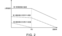
- FIG. 2 shows an example of the relationship between the temperature of the first combustion region, the natural gas flow rate of the first injection part, the natural gas flow rate of the second injection part, and the co-combustion rate in the combustion system according to the embodiment of the present disclosure.
- FIG. FIG. 3 is an example of the relationship between the temperature of the first combustion region, the natural gas flow rate of the first injection part, the natural gas flow rate of the second injection part, and the engine load in the combustion system according to the embodiment of the present disclosure.
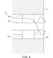
- FIG. FIG. 4 is a diagram illustrating an example of the configuration of the air injection section of the first burner according to the embodiment of the present disclosure.
- FIG. 1 is a schematic diagram showing the configuration of a combustion system 1 according to the present embodiment.
- the combustion system 1 is a gas turbine system that is an example of a combustion system that generates energy by burning fuel.
- the combustion system 1 includes a compressor 11a, a turbine 11b, a combustor 12, a first burner 13, a second burner 14, an ammonia supply source 15, and a natural gas supply source 16. , a temperature sensor 17, and a control device 18.
- the combustion system 1 also includes an engine E1 including a compressor 11a, a turbine 11b, and a combustor 12.
- Engine E1 is a gas turbine engine.
- the compressor 11a and the turbine 11b rotate as a unit.
- the compressor 11a and the turbine 11b are connected to each other by a shaft.
- the compressor 11a is provided in an intake flow path 101 connected to the combustor 12. Air supplied to the combustor 12 flows through the intake flow path 101 . An intake port (not shown) through which air is taken in from the outside is provided at the upstream end of the intake flow path 101. Air taken in from the intake port passes through the compressor 11a and is sent to the combustor 12. The compressor 11a compresses air and discharges it downstream.
- the turbine 11b is provided in an exhaust flow path 102 connected to the combustor 12. Exhaust gas discharged from the combustor 12 flows through the exhaust flow path 102 . Exhaust gas discharged from the combustor 12 passes through the turbine 11b and is sent to the downstream side of the turbine 11b in the exhaust flow path 102. The turbine 11b generates rotational power by being rotated by exhaust gas.
- a generator (not shown) is connected to the compressor 11a.
- the rotational power transmitted from the turbine 11b to the compressor 11a is used for power generation by the generator.
- the combustor 12 can be supplied with air, ammonia, and natural gas, respectively, as will be described later.
- Air compressed by a compressor 11a is supplied to the combustor 12 from an intake flow path 101.
- combustion is performed using at least one of ammonia and natural gas as fuel. That is, in the combustor 12, both ammonia and natural gas may be used as fuel, or only one of ammonia and natural gas may be used as fuel.
- Ammonia corresponds to the first fuel.
- Natural gas corresponds to an example of a second fuel that does not contain nitrogen atoms. However, the second fuel is not limited to natural gas.
- the second fuel may be, for example, natural gas, hydrogen or kerosene, or a combination thereof.
- Exhaust gas generated in the combustor 12 is discharged into the exhaust flow path 102.
- the combustor 12 includes a first combustion region 12a and a second combustion region 12b as combustion regions where fuel is combusted.
- the first combustion region 12a is located upstream of the second combustion region 12b in the gas flow direction within the combustor 12.
- the second combustion zone 12b is continuous to the first combustion zone 12a on the downstream side.
- the combustion area including the first combustion area 12a and the second combustion area 12b is, for example, a space defined by a cylindrical wall.
- the upstream side of the space corresponds to the first combustion area 12a, and the downstream side of the space corresponds to the second combustion area 12b.
- the exhaust flow path 102 described above is connected to the downstream end of the second combustion region 12b.
- the combustor 12 is provided with a first burner 13 and a second burner 14 as burners that inject fuel and air to each combustion region to form a flame.
- the first burner 13 faces the first combustion area 12a and injects fuel and air into the first combustion area 12a.
- the first burner 13 is provided at the upstream end of the first combustion region 12a.
- FIG. 1 shows an example in which the number of first burners 13 is one. However, the number of first burners 13 may be plural.
- the positional relationship of the plurality of first burners 13 is not limited.
- the plurality of first burners 13 may be provided at intervals in the circumferential direction of the first combustion region 12a.
- the first burner 13 includes an ammonia injection section 21, a natural gas injection section 22a, and an air injection section 23a. Each of these injection parts faces the first combustion area 12a. That is, fuel or air is injected from each of these injection parts into the first combustion region 12a.
- the ammonia injection section 21 includes a flow path that is supplied with ammonia and communicates with the first combustion region 12a. Ammonia supplied to the flow path is injected into the first combustion region 12a.
- the natural gas injection part 22a includes a flow path that is supplied with natural gas and communicates with the first combustion region 12a. The natural gas supplied to the flow path is injected into the first combustion region 12a.
- the air injection section 23a includes a flow path through which air is supplied and communicates with the first combustion region 12a. The air supplied to the flow path is injected into the first combustion area 12a.
- the second burner 14 faces the second combustion area 12b and injects fuel and air into the second combustion area 12b.
- the second burner 14 is provided on the side of the second combustion area 12b.
- FIG. 1 shows an example in which the number of second burners 14 is one. However, the number of second burners 14 may be plural.
- the positional relationship of the plurality of second burners 14 is not limited.
- the plurality of second burners 14 may be provided at intervals in the circumferential direction of the second combustion region 12b.
- the second burner 14 includes a natural gas injection section 22b and an air injection section 23b. Each of these injection parts faces the second combustion area 12b. That is, fuel or air is injected from each of these injection parts into the second combustion region 12b.
- the natural gas injection section 22b includes a flow path that is supplied with natural gas and communicates with the second combustion region 12b.
- the natural gas supplied to the flow path is injected into the second combustion region 12b.
- the air injection section 23b includes a flow path through which air is supplied and communicates with the second combustion region 12b. The air supplied to the flow path is injected into the second combustion region 12b.
- the natural gas injection part 22a of the first burner 13 is also referred to as the first injection part 22a.
- the natural gas injection part 22b of the second burner 14 is also referred to as a second injection part 22b.
- the compressor 11a compresses and discharges air. Air is supplied from the compressor 11a to the first burner 13 and the second burner 14 via the intake flow path 101.
- the intake flow path 101 includes a flow path 101a, a flow path 101b, and a flow path 101c.
- the compressor 11a is provided in the flow path 101a.
- the flow path 101a branches into a flow path 101b and a flow path 101c on the downstream side of the compressor 11a.
- the flow path 101b is connected to the air injection part 23a of the first burner 13. Therefore, air can be supplied from the compressor 11a to the air injection part 23a of the first burner 13 via the flow path 101a and the flow path 101b.
- the flow path 101c is connected to the air injection part 23b of the second burner 14. Therefore, air can be supplied from the compressor 11a to the air injection part 23b of the second burner 14 via the flow path 101a and the flow path 101c.
- the ammonia supply source 15 is, for example, an ammonia tank that stores ammonia.
- ammonia is stored in a liquid state in the ammonia tank.
- the ammonia supply source 15 is not limited to an ammonia tank.
- the ammonia supply source 15 may be a device that generates ammonia.
- the ammonia supply source 15 is connected to the ammonia injection section 21 of the first burner 13 via a flow path 103. Therefore, ammonia can be supplied from the ammonia supply source 15 to the ammonia injection section 21 of the first burner 13 via the flow path 103. Supply of ammonia from the ammonia supply source 15 to the first burner 13 is realized, for example, by a pump (not shown).
- a flow control valve 31 is provided in the flow path 103 .
- the flow rate control valve 31 adjusts the flow rate of ammonia sent to the first burner 13 through the flow path 103. Specifically, the amount of ammonia supplied to the first burner 13 is adjusted by adjusting the opening degree of the flow control valve 31.
- the natural gas supply source 16 is, for example, a natural gas tank that stores natural gas.
- natural gas is stored in a liquid state in a natural gas tank.
- the natural gas supply source 16 is not limited to a natural gas tank.
- the natural gas supply source 16 may be a device that generates natural gas.
- the natural gas supply source 16 is connected to the flow path 104.
- the flow path 104 branches into a flow path 105 and a flow path 106.
- the flow path 105 is connected to the natural gas injection part 22a of the first burner 13. Therefore, natural gas can be supplied from the natural gas supply source 16 to the natural gas injection part 22a of the first burner 13 via the flow path 104 and the flow path 105.
- the flow path 106 is connected to the natural gas injection part 22b of the second burner 14. Therefore, natural gas can be supplied from the natural gas supply source 16 to the natural gas injection part 22b of the second burner 14 via the flow path 104 and the flow path 106.
- Supply of ammonia from the natural gas supply source 16 to the first burner 13 and the second burner 14 is realized by, for example, a pump (not shown).
- a flow control valve 32 is provided in the flow path 105.
- the flow rate control valve 32 adjusts the flow rate of natural gas sent to the first burner 13 through the flow path 105. Specifically, the amount of natural gas supplied to the first burner 13 is adjusted by adjusting the opening degree of the flow rate control valve 32.
- a flow control valve 33 is provided in the flow path 106 .
- the flow rate control valve 33 adjusts the flow rate of natural gas sent to the second burner 14 through the flow path 106. Specifically, the amount of natural gas supplied to the second burner 14 is adjusted by adjusting the opening degree of the flow rate control valve 33.
- the temperature sensor 17 detects the temperature of the first combustion region 12a of the combustor 12.
- the temperature sensor 17 is provided, for example, on the side of the first combustion region 12a.
- the control device 18 includes a central processing unit (CPU), a ROM in which programs and the like are stored, and a RAM as a work area.
- the functions of the control device 18 are realized by a central processing unit, ROM, and the like.
- the control device 18 controls the operation of each device within the combustion system 1. For example, the control device 18 controls the operation of the flow control valves 31, 32, and 33, respectively. Further, the control device 18 acquires information from the temperature sensor 17.
- the control device 18 controls the flow rate of ammonia injected from the ammonia injection part 21 of the first burner 13. Specifically, the control device 18 controls the flow rate of ammonia injected from the injection part 21 of the first burner 13 by controlling the operation of the flow rate control valve 31 .
- the control device 18 controls the flow rate of natural gas injected from the first injection part 22a, which is the natural gas injection part of the first burner 13. Specifically, the control device 18 controls the flow rate of natural gas injected from the first injection part 22a of the first burner 13 by controlling the operation of the flow rate control valve 32.
- the control device 18 controls the flow rate of natural gas injected from the second injection part 22b, which is the natural gas injection part of the second burner 14. Specifically, the control device 18 controls the flow rate of natural gas injected from the second injection part 22b of the second burner 14 by controlling the operation of the flow rate control valve 33.
- the control device 18 controls the flow rate of ammonia injected from the injection part 21 of the first burner 13, the flow rate of natural gas injected from the first injection part 22a of the first burner 13, and the flow rate of the natural gas injected from the first injection part 22a of the first burner 13.
- the flow rate of natural gas injected from the fourteen second injection parts 22b can be individually controlled. Therefore, the control device 18 can control the ratio of the amount of ammonia supplied to the combustor 12 and the amount of natural gas supplied to the combustor 12. That is, the control device 18 can control the co-firing rate, which is the ratio of the calorific value of ammonia to the total calorific value of ammonia and natural gas in the combustor 12.
- the control device 18 controls the flow rate of natural gas injected from the first natural gas injection part 22a of the first burner 13 and the flow rate of natural gas injected from the second natural gas injection part 22b of the second burner 14.
- the natural gas flow rate ratio which is the ratio to the flow rate, can be adjusted.
- the second fuel is not limited to natural gas. Therefore, the natural gas flow rate ratio is an example of the second fuel flow rate ratio, which is the ratio between the flow rate of the second fuel injected from the first injection part 22a and the flow rate of the second fuel injected from the second injection part 22b. corresponds to
- the temperature of the flame formed in the first combustion region 12a becomes excessively high, there is a risk that devices such as the liner of the combustor 12 or the first burner 13 will be damaged.
- the flame temperature of the second fuel such as natural gas is higher than that of ammonia, when the co-firing rate is low, if natural gas is injected only from the first injection part 22a of the first burner 13, There is a possibility that the temperature of the flame formed in the first combustion region 12a becomes excessively high.
- the control device 18 controls the flow rate of natural gas injected from the first natural gas injection part 22a of the first burner 13 and the second injection of natural gas of the second burner 14.
- the natural gas flow rate ratio which is the ratio to the flow rate of natural gas injected from the section 22b, is adjusted. Therefore, without injecting all of the natural gas supplied to the combustor 12 from the first injection part 22a of the first burner 13, a part of the natural gas supplied to the combustor 12 is injected from the second injection part 22a of the second burner 14. It can be injected from the injection part 22b. Therefore, it is possible to prevent the temperature of the flame formed in the first combustion region 12a from becoming excessively high, and therefore damage to the device due to the flame can be suppressed.
- the control device 18 adjusts the natural gas flow rate ratio based on the temperature of the first combustion region 12a, for example.
- An example in which the natural gas flow rate ratio is adjusted based on the temperature of the first combustion region 12a will be described below.
- the control device 18 may adjust the natural gas flow rate ratio based on parameters other than the temperature of the first combustion region 12a.
- the control device 18 when the temperature of the first combustion region 12a is lower than the upper limit temperature, the control device 18 causes all of the natural gas supplied to the combustor 12 to be injected from the first injection part 22a of the first burner 13, and the second burner The natural gas flow rate ratio is adjusted so that natural gas is not injected from the 14 second injection parts 22b.
- the control device 18 controls a part of the natural gas supplied to the combustor 12 to be injected from the second injection part 22b of the second burner 14. Adjust the natural gas flow rate ratio so that The upper limit temperature can be set as appropriate, taking into consideration the heat resistance of each device near the first combustion region 12a.
- FIG. 2 is a diagram showing an example of the relationship between the temperature of the first combustion region 12a, the natural gas flow rate of the first injection part 22a, the natural gas flow rate of the second injection part 22b, and the co-combustion rate in the combustion system 1.
- the natural gas flow rate of the first injection part 22a means the flow rate of natural gas injected from the first injection part 22a of the first burner 13.
- the natural gas flow rate of the second injection part 22b means the flow rate of natural gas injected from the second injection part 22b of the second burner 14.
- the temperature of the first combustion region 12a, the natural gas flow rate of the first injection part 22a, and the natural gas flow rate of the second injection part 22b are shown by a solid line, a dashed line, and a broken line, respectively.
- the higher the co-combustion rate the higher the ratio of the total amount of ammonia supplied to the total amount of fuel supplied to the combustor 12.
- the lower the co-combustion rate the higher the ratio of the total amount of natural gas supplied to the total amount of fuel supplied to the combustor 12.
- the load on engine E1 is constant.
- the total calorific value of the fuel supplied to the combustor 12 is also approximately constant.
- the process in which the co-firing rate decreases from a high state corresponds to the process in which the co-firing rate decreases from a high state.
- the temperature of the first combustion region 12a is lower than the upper limit temperature. Therefore, all of the natural gas supplied to the combustor 12 is injected from the first injection part 22a of the first burner 13, and no natural gas is injected from the second injection part 22b of the second burner 14.
- the control device 18 adjusts the natural gas flow rate ratio so that the temperature of the first combustion region 12a is maintained at the upper limit temperature in a region where the co-combustion rate is lower than the value R1.
- the control device 18 controls the ratio of the natural gas flow rate of the second injection part 22b to the total flow rate of natural gas. Adjust the natural gas flow rate ratio so that it becomes higher. As a result, as shown in FIG. 2, in a region where the co-firing rate is lower than the value R1, as the co-firing rate decreases, the ratio of the natural gas flow rate of the second injection part 22b to the total flow rate of natural gas increases. Thereby, the temperature of the first combustion region 12a is maintained at the upper limit temperature. As shown in FIG.
- natural gas is injected from the second injection part 22b of the second burner 14 in a region where the temperature of the first combustion region 12a is lower than the upper limit temperature (that is, a region where the co-combustion rate is higher than the value R1). All of the natural gas supplied to the combustor 12 is injected from the first injection part 22a of the first burner 13. This prevents the temperature of the first combustion region 12a from decreasing excessively. Therefore, the stability of the flame in the first combustion region 12a is ensured.
- FIG. 3 shows an example of the relationship between the temperature of the first combustion region 12a, the natural gas flow rate of the first injection part 22a, the natural gas flow rate of the second injection part 22b, and the load of the engine E1 in the combustion system 1. It is a diagram.
- the temperature of the first combustion region 12a, the natural gas flow rate of the first injection section 22a, and the natural gas flow rate of the second injection section 22b are indicated by a solid line, a dashed line, and a broken line, respectively. has been done.
- the load on the engine E1 varies depending on, for example, the required amount of power generated by the generator connected to the compressor 11a.
- the control device 18 adjusts the natural gas flow rate ratio so that the temperature of the first combustion region 12a is maintained at the upper limit temperature in a region where the load of the engine E1 is greater than the value L1.
- the control device 18 controls the flow rate of natural gas in the second injection part 22b relative to the total flow rate of natural gas. Adjust the natural gas flow rate ratio so that the ratio becomes higher.
- the ratio of the natural gas flow rate of the second injection part 22b to the total flow rate of natural gas increases. Become. Thereby, the temperature of the first combustion region 12a is maintained at the upper limit temperature.
- the control device 18 adjusts the natural gas flow rate ratio based on the temperature of the first combustion region 12a. Thereby, it is possible to suppress the temperature of the flame formed in the first combustion region 12a from becoming excessively high. Specifically, when the co-combustion rate is low or when the load on the engine E1 is large, it is possible to suppress the temperature of the first combustion region 12a from exceeding the upper limit temperature. Therefore, damage to the device due to flame can be suppressed. Furthermore, it is possible to suppress the temperature of the first combustion region 12a from decreasing excessively. Specifically, when the co-combustion rate is high or when the load on the engine E1 is small, it is possible to suppress the temperature of the first combustion region 12a from decreasing excessively. Therefore, the stability of the flame in the first combustion region 12a is ensured.
- control device 18 may adjust the natural gas flow rate ratio based on parameters other than the temperature of the first combustion region 12a.
- the control device 18 may adjust the natural gas flow rate ratio based on the co-firing rate. For example, information about the co-firing rate that changes according to a preset schedule is input to the control device 18. The control device 18 can obtain the co-firing rate using this information. For example, when the co-combustion rate is higher than the value R1 in FIG. The natural gas flow rate ratio is adjusted so that natural gas is not injected from the second injection part 22b.
- control device 18 controls the control device 18 so that, for example, when the co-combustion rate is lower than the value R1 in FIG. Then, adjust the natural gas flow rate ratio. Specifically, when the co-firing rate is lower than the value R1 in FIG. 2, the control device 18 causes the ratio of the natural gas flow rate of the second injection part 22b to the total flow rate of natural gas to increase as the co-firing rate decreases. Adjust the natural gas flow ratio accordingly.
- the temperature of the first combustion area 12a is the upper limit temperature, similar to the case where the natural gas flow rate ratio is adjusted based on the temperature of the first combustion area 12a. Since it is possible to suppress the flame from exceeding the maximum value, it is possible to suppress damage to the device caused by the flame. Furthermore, since the temperature of the first combustion region 12a can be prevented from decreasing excessively, the stability of the flame in the first combustion region 12a is ensured.
- the control device 18 may adjust the natural gas flow rate ratio based on the load of the engine E1. For example, information on the load of the engine E1 that changes according to a preset schedule is input to the control device 18. The control device 18 can obtain the load of the engine E1 using the information. For example, when the load of the engine E1 is smaller than the value L1 in FIG. The natural gas flow rate ratio is adjusted so that natural gas is not injected from the second injection part 22b of the burner 14.
- control device 18 controls, for example, when the load of the engine E1 is larger than the value L1 in FIG. Adjust the natural gas flow rate ratio so that Specifically, when the load on the engine E1 is larger than the value L1 in FIG. 3, the control device 18 adjusts the natural gas flow rate of the second injection part 22b with respect to the total flow rate of natural gas as the load on the engine E1 increases. Adjust the natural gas flow rate ratio so that the ratio becomes higher.
- the temperature of the first combustion area 12a is Since it is possible to prevent the temperature from exceeding the upper limit temperature, damage to the device due to flames can be suppressed. Furthermore, since the temperature of the first combustion region 12a can be prevented from decreasing excessively, the stability of the flame in the first combustion region 12a is ensured.
- the control device 18 may adjust the natural gas flow rate ratio based on the total calorific value of ammonia and natural gas. For example, information on the load of the engine E1 that changes according to a preset schedule is input to the control device 18. Using this information, the control device 18 can obtain the total calorific value of ammonia and natural gas. The total calorific value has a correlation with the load of the engine E1. Therefore, for example, when the total calorific value is smaller than the threshold value, the control device 18 injects all the natural gas supplied to the combustor 12 from the first injection part 22a of the first burner 13 and The natural gas flow rate ratio is adjusted so that natural gas is not injected from the second injection part 22b.
- control device 18 controls the natural gas so that, for example, when the total calorific value is larger than the threshold value, a part of the natural gas supplied to the combustor 12 is injected from the second injection part 22b of the second burner 14. Adjust the flow ratio. Specifically, when the total calorific value is larger than the threshold value, the control device 18 controls such that as the load of the total calorific value increases, the ratio of the natural gas flow rate of the second injection part 22b to the total natural gas flow rate increases. Then, adjust the natural gas flow rate ratio.
- the temperature of the first combustion region 12a, the co-combustion rate, the load of the engine E1, and the total calorific value have been described as parameters used to adjust the natural gas flow rate ratio.
- a plurality of types of parameters among these parameters may be used in combination as parameters used to adjust the natural gas flow rate ratio.
- parameters other than those described above may be used as parameters used to adjust the natural gas flow rate ratio.
- the air injection part 23a of the first burner 13 be devised as described below.
- such a device will be explained with reference to FIG. 4.
- FIG. 4 is a diagram showing an example of the configuration of the air injection part 23a of the first burner 13.
- the first burner 13 includes a rotating portion 24.
- the swirling section 24 swirls the air injected from the air injection section 23a of the first burner 13.
- the rotating section 24 includes a shaft 24a and a rotating blade 24b.
- the shaft 24a extends, for example, on the central axis of the air flow path in the injection section 23a.
- the swirler blade 24b extends radially outward from the outer peripheral surface of the shaft 24a.
- a plurality of swirl vanes 24b are provided at intervals in the circumferential direction of the shaft 24a.
- a swirling force is applied to the air flowing through the injection portion 23a.
- the swirling section 24 is not limited to the example shown in FIG. 4 as long as it can swirl the air injected from the air injection section 23a of the first burner 13.
- the first burner 13 includes the swirling part 24 that swirls the air injected from the air injection part 23a of the first burner 13. Thereby, the stability of the flame in the first combustion region 12a is ensured.
- the rotating portion 24 may be omitted from the first burner 13.
- the rotational power transmitted from the turbine 11b to the compressor 11a is used as energy to drive the generator.
- the rotational power transmitted from the turbine 11b to the compressor 11a may be used for other purposes, such as for driving a moving body such as a ship.
- ammonia injection section 21 and the natural gas injection section 22a are separate injection sections in the first burner 13.
- ammonia and natural gas may be mixed in advance and injected into the first combustion region 12a from one injection part.
- one injection part also functions as an ammonia injection part and also functions as a natural gas injection part.
- ammonia and air may be mixed in advance and injected into the first combustion region 12a from one injection part.
- ammonia, natural gas, and air may be mixed in advance and injected into the first combustion region 12a from one injection part.
- natural gas and air may be mixed in advance and injected from one injection part into the second combustion area 12b.
- the present disclosure contributes to suppressing damage to equipment caused by flames in combustion systems such as gas turbine systems, so for example, the present disclosure contributes to reducing damage to equipment caused by flames in combustion systems such as gas turbine systems. can contribute to ensuring access to
- Combustion system 12 Combustor 12a: First combustion zone 12b: Second combustion zone 13: First burner 14: Second burner 18: Control device 21: Ammonia injection section 22a: Natural gas injection section (first Injection part) 22b: Natural gas injection part (second injection part) 23a: Air injection part 24: Swivel part E1: Engine
Abstract
燃焼システム(1)は、第1燃焼領域(12a)と、第1燃焼領域(12a)に対して下流側に連続する第2燃焼領域(12b)とを含む燃焼器(12)と、第1燃焼領域(12a)に臨む第1燃料としてのアンモニアの噴射部(21)と、第1燃焼領域(12a)に臨む窒素原子を含まない第2燃料の第1噴射部(22a)とを含む第1バーナ(13)と、第2燃焼領域(12b)に臨む第2燃料の第2噴射部(22b)を含む第2バーナ(14)と、第1噴射部(22a)から噴射される第2燃料の流量と、第2噴射部(22b)から噴射される第2燃料の流量との比である第2燃料流量比を調整する制御装置(18)と、を備える。
Description
本開示は、燃焼システムに関する。本出願は2022年3月25日に提出された日本特許出願第2022-049708号に基づく優先権の利益を主張するものであり、その内容は本出願に援用される。
燃焼器で燃料を燃焼させることによって動力を得るガスタービンシステム等の燃焼システムが利用されている。ガスタービンシステム等の燃焼システムとして、例えば、特許文献1に開示されているように、アンモニアを燃料として用いるものがある。アンモニアを燃料として用いることによって、二酸化炭素の排出が抑制される。
アンモニアを燃料として用いる燃焼システムでは、第1燃料としてのアンモニアに加えて、天然ガス等の窒素原子を含まない第2燃料が併用される場合がある。天然ガス等の第2燃料の火炎温度は、アンモニアの火炎温度と比較して高い。ゆえに、例えば、アンモニアおよび第2燃料の総発熱量に対するアンモニアの発熱量の比率である混焼率が低い場合等において、火炎によるバーナ等の装置の損傷を抑制することが望まれている。
本開示の目的は、火炎による装置の損傷を抑制することが可能な燃焼システムを提供することである。
上記課題を解決するために、本開示の燃焼システムは、第1燃焼領域と、第1燃焼領域に対して下流側に連続する第2燃焼領域とを含む燃焼器と、第1燃焼領域に臨む第1燃料としてのアンモニアの噴射部と、第1燃焼領域に臨む窒素原子を含まない第2燃料の第1噴射部とを含む第1バーナと、第2燃焼領域に臨む第2燃料の第2噴射部を含む第2バーナと、第1噴射部から噴射される第2燃料の流量と、第2噴射部から噴射される第2燃料の流量との比である第2燃料流量比を調整する制御装置と、を備える。
制御装置は、第1燃焼領域の温度に基づいて、第2燃料流量比を調整してもよい。
制御装置は、アンモニアおよび第2燃料の総発熱量に対するアンモニアの発熱量の比率である混焼率に基づいて、第2燃料流量比を調整してもよい。
燃焼器を含むエンジンを備え、制御装置は、エンジンの負荷に基づいて、第2燃料流量比を調整してもよい。
制御装置は、アンモニアおよび第2燃料の総発熱量に基づいて、第2燃料流量比を調整してもよい。
第1バーナは、第1燃焼領域に臨む空気の噴射部と、空気の噴射部から噴射される空気を旋回させる旋回部と、を備えてもよい。
本開示によれば、火炎による装置の損傷を抑制することができる。
以下に添付図面を参照しながら、本開示の実施形態について説明する。実施形態に示す寸法、材料、その他具体的な数値等は、理解を容易とするための例示にすぎず、特に断る場合を除き、本開示を限定するものではない。なお、本明細書および図面において、実質的に同一の機能、構成を有する要素については、同一の符号を付することにより重複説明を省略し、また本開示に直接関係のない要素は図示を省略する。
図1は、本実施形態に係る燃焼システム1の構成を示す模式図である。燃焼システム1は、燃料を燃焼させることによりエネルギーを生成する燃焼システムの一例に相当するガスタービンシステムである。図1に示すように、燃焼システム1は、圧縮機11aと、タービン11bと、燃焼器12と、第1バーナ13と、第2バーナ14と、アンモニア供給源15と、天然ガス供給源16と、温度センサ17と、制御装置18とを備える。また、燃焼システム1は、圧縮機11aと、タービン11bと、燃焼器12とを含むエンジンE1を備える。エンジンE1は、ガスタービンエンジンである。
圧縮機11aおよびタービン11bは、一体として回転する。圧縮機11aとタービン11bとは、シャフトによって互いに連結されている。
圧縮機11aは、燃焼器12と接続される吸気流路101に設けられている。吸気流路101には、燃焼器12に供給される空気が流通する。吸気流路101の上流側の端部には、空気が外部から取り込まれる不図示の吸気口が設けられる。吸気口から取り込まれた空気は、圧縮機11aを通過して、燃焼器12に送られる。圧縮機11aは、空気を圧縮して下流側に吐出する。
タービン11bは、燃焼器12と接続される排気流路102に設けられている。排気流路102には、燃焼器12から排出された排気ガスが流通する。燃焼器12から排出された排気ガスは、タービン11bを通過して、排気流路102のうちタービン11bより下流側に送られる。タービン11bは、排気ガスによって回されることによって、回転動力を生成する。
圧縮機11aには、不図示の発電機が接続されている。タービン11bから圧縮機11aに伝達された回転動力は、当該発電機による発電に利用される。
燃焼器12には、後述するように、空気、アンモニアおよび天然ガスがそれぞれ供給可能となっている。燃焼器12には、圧縮機11aにより圧縮された空気が吸気流路101から供給される。燃焼器12では、アンモニアおよび天然ガスの少なくとも一方を燃料として用いて燃焼が行われる。つまり、燃焼器12では、アンモニアおよび天然ガスの両方が燃料として用いられてもよく、アンモニアおよび天然ガスの一方のみが燃料として用いられてもよい。アンモニアは、第1燃料に相当する。天然ガスは、窒素原子を含まない第2燃料の一例に相当する。ただし、第2燃料は、天然ガスに限定されない。第2燃料は、例えば、天然ガス、水素もしくは灯油、または、これらの組み合わせであってもよい。燃焼器12で生じた排気ガスは、排気流路102に排出される。
燃焼器12は、燃料が燃焼する燃焼領域として、第1燃焼領域12aと、第2燃焼領域12bとを含む。第1燃焼領域12aは、燃焼器12内におけるガスの流れ方向において、第2燃焼領域12bよりも上流側に位置する。第2燃焼領域12bは、第1燃焼領域12aに対して下流側に連続する。第1燃焼領域12aおよび第2燃焼領域12bを含む燃焼領域は、例えば、円筒形状の壁部により区画される空間である。当該空間の上流側が第1燃焼領域12aに相当し、当該空間の下流側が第2燃焼領域12bに相当する。上述した排気流路102は、第2燃焼領域12bの下流端に接続されている。燃焼器12には、火炎を形成するための燃料および空気を各燃焼領域に噴射するバーナとして、第1バーナ13と、第2バーナ14とが設けられている。
第1バーナ13は、第1燃焼領域12aに臨み、第1燃焼領域12aに燃料および空気を噴射する。第1バーナ13は、第1燃焼領域12aの上流端に設けられる。図1では、第1バーナ13の数が1つである例が示されている。ただし、第1バーナ13の数は複数であってもよい。複数の第1バーナ13の位置関係は限定されない。例えば、複数の第1バーナ13は、第1燃焼領域12aの周方向に間隔を空けて設けられてもよい。第1バーナ13は、アンモニアの噴射部21と、天然ガスの噴射部22aと、空気の噴射部23aとを含む。これらの各噴射部は、第1燃焼領域12aに臨む。つまり、これらの各噴射部から第1燃焼領域12aに燃料または空気が噴射される。
アンモニアの噴射部21は、具体的には、アンモニアが供給され第1燃焼領域12aと連通する流路を含む。当該流路に供給されたアンモニアが第1燃焼領域12aに噴射される。天然ガスの噴射部22aは、具体的には、天然ガスが供給され第1燃焼領域12aと連通する流路を含む。当該流路に供給された天然ガスが第1燃焼領域12aに噴射される。空気の噴射部23aは、具体的には、空気が供給され第1燃焼領域12aと連通する流路を含む。当該流路に供給された空気が第1燃焼領域12aに噴射される。
第2バーナ14は、第2燃焼領域12bに臨み、第2燃焼領域12bに燃料および空気を噴射する。第2バーナ14は、第2燃焼領域12bの側部に設けられる。図1では、第2バーナ14の数が1つである例が示されている。ただし、第2バーナ14の数は複数であってもよい。複数の第2バーナ14の位置関係は限定されない。例えば、複数の第2バーナ14は、第2燃焼領域12bの周方向に間隔を空けて設けられてもよい。第2バーナ14は、天然ガスの噴射部22bと、空気の噴射部23bとを含む。これらの各噴射部は、第2燃焼領域12bに臨む。つまり、これらの各噴射部から第2燃焼領域12bに燃料または空気が噴射される。
天然ガスの噴射部22bは、具体的には、天然ガスが供給され第2燃焼領域12bと連通する流路を含む。当該流路に供給された天然ガスが第2燃焼領域12bに噴射される。空気の噴射部23bは、具体的には、空気が供給され第2燃焼領域12bと連通する流路を含む。当該流路に供給された空気が第2燃焼領域12bに噴射される。
以下では、天然ガスの噴射部のうち、第1バーナ13の天然ガスの噴射部22aを第1噴射部22aとも呼ぶ。天然ガスの噴射部のうち、第2バーナ14の天然ガスの噴射部22bを第2噴射部22bとも呼ぶ。
上述したように、圧縮機11aは、空気を圧縮して吐出する。圧縮機11aから第1バーナ13および第2バーナ14へ吸気流路101を介して空気が供給される。吸気流路101は、流路101aと、流路101bと、流路101cとを含む。圧縮機11aは、流路101aに設けられる。流路101aは、圧縮機11aよりも下流側において、流路101bと流路101cに分岐している。
流路101bは、第1バーナ13の空気の噴射部23aと接続されている。ゆえに、圧縮機11aから第1バーナ13の空気の噴射部23aへ、流路101aおよび流路101bを介して空気を供給できる。流路101cは、第2バーナ14の空気の噴射部23bと接続されている。ゆえに、圧縮機11aから第2バーナ14の空気の噴射部23bへ、流路101aおよび流路101cを介して空気を供給できる。
アンモニア供給源15は、例えば、アンモニアを貯蔵するアンモニアタンクである。アンモニアタンクには、例えば、アンモニアが液体の状態で貯蔵される。ただし、アンモニア供給源15は、アンモニアタンクに限定されない。例えば、アンモニア供給源15は、アンモニアを生成する装置等であってもよい。
アンモニア供給源15は、流路103を介して第1バーナ13のアンモニアの噴射部21と接続されている。ゆえに、アンモニア供給源15から第1バーナ13のアンモニアの噴射部21へ、流路103を介してアンモニアを供給できる。アンモニア供給源15から第1バーナ13へのアンモニアの供給は、例えば、不図示のポンプによって実現される。流路103には、流量制御弁31が設けられる。流量制御弁31は、流路103を通り第1バーナ13に送られるアンモニアの流量を調整する。具体的には、流量制御弁31の開度が調整されることによって、第1バーナ13へのアンモニアの供給量が調整される。
天然ガス供給源16は、例えば、天然ガスを貯蔵する天然ガスタンクである。天然ガスタンクには、例えば、天然ガスが液体の状態で貯蔵される。ただし、天然ガス供給源16は、天然ガスタンクに限定されない。例えば、天然ガス供給源16は、天然ガスを生成する装置等であってもよい。
天然ガス供給源16は、流路104と接続されている。流路104は、流路105と流路106に分岐している。流路105は、第1バーナ13の天然ガスの噴射部22aと接続されている。ゆえに、天然ガス供給源16から第1バーナ13の天然ガスの噴射部22aへ、流路104および流路105を介して天然ガスを供給できる。流路106は、第2バーナ14の天然ガスの噴射部22bと接続されている。ゆえに、天然ガス供給源16から第2バーナ14の天然ガスの噴射部22bへ、流路104および流路106を介して天然ガスを供給できる。天然ガス供給源16から第1バーナ13および第2バーナ14へのアンモニアの供給は、例えば、不図示のポンプによって実現される。
流路105には、流量制御弁32が設けられる。流量制御弁32は、流路105を通り第1バーナ13に送られる天然ガスの流量を調整する。具体的には、流量制御弁32の開度が調整されることによって、第1バーナ13への天然ガスの供給量が調整される。流路106には、流量制御弁33が設けられる。流量制御弁33は、流路106を通り第2バーナ14に送られる天然ガスの流量を調整する。具体的には、流量制御弁33の開度が調整されることによって、第2バーナ14への天然ガスの供給量が調整される。
温度センサ17は、燃焼器12の第1燃焼領域12aの温度を検出する。温度センサ17は、例えば、第1燃焼領域12aの側部に設けられる。
制御装置18は、中央処理装置(CPU)、プログラム等が格納されたROM、ワークエリアとしてのRAM等を含む。制御装置18の機能は、中央処理装置およびROM等によって実現される。制御装置18は、燃焼システム1内の各装置の動作を制御する。例えば、制御装置18は、流量制御弁31、32、33の動作をそれぞれ制御する。また、制御装置18は、温度センサ17から情報を取得する。
制御装置18は、第1バーナ13のアンモニアの噴射部21から噴射されるアンモニアの流量を制御する。具体的には、制御装置18は、流量制御弁31の動作を制御することによって、第1バーナ13の噴射部21から噴射されるアンモニアの流量を制御する。
制御装置18は、第1バーナ13の天然ガスの噴射部である第1噴射部22aから噴射される天然ガスの流量を制御する。具体的には、制御装置18は、流量制御弁32の動作を制御することによって、第1バーナ13の第1噴射部22aから噴射される天然ガスの流量を制御する。
制御装置18は、第2バーナ14の天然ガスの噴射部である第2噴射部22bから噴射される天然ガスの流量を制御する。具体的には、制御装置18は、流量制御弁33の動作を制御することによって、第2バーナ14の第2噴射部22bから噴射される天然ガスの流量を制御する。
上記のように、制御装置18は、第1バーナ13の噴射部21から噴射されるアンモニアの流量、第1バーナ13の第1噴射部22aから噴射される天然ガスの流量、および、第2バーナ14の第2噴射部22bから噴射される天然ガスの流量を個別に制御できる。ゆえに、制御装置18は、燃焼器12へのアンモニアの供給量と、燃焼器12への天然ガスの供給量との比を制御できる。つまり、制御装置18は、燃焼器12におけるアンモニアおよび天然ガスの総発熱量に対するアンモニアの発熱量の比率である混焼率を制御できる。
さらに、制御装置18は、第1バーナ13の天然ガスの第1噴射部22aから噴射される天然ガスの流量と、第2バーナ14の天然ガスの第2噴射部22bから噴射される天然ガスの流量との比である天然ガス流量比を調整できる。上述したように、第2燃料は、天然ガスに限定されない。ゆえに、天然ガス流量比は、第1噴射部22aから噴射される第2燃料の流量と、第2噴射部22bから噴射される第2燃料の流量との比である第2燃料流量比の一例に相当する。
燃焼システム1では、第1燃焼領域12aで形成される火炎の温度が過度に高くなると、燃焼器12のライナーまたは第1バーナ13等の装置が損傷するおそれがある。例えば、天然ガス等の第2燃料の火炎温度はアンモニアの火炎温度と比較して高いので、混焼率が低い場合に、天然ガスを第1バーナ13の第1噴射部22aのみから噴射させると、第1燃焼領域12aで形成される火炎の温度が過度に高くなるおそれがある。例えば、エンジンE1の負荷が高い場合、燃焼器12へ供給される燃料の総供給量が多くなるので、天然ガスを第1バーナ13の第1噴射部22aのみから噴射させると、第1燃焼領域12aで形成される火炎の温度が過度に高くなるおそれがある。
以上説明したように、燃焼システム1では、制御装置18は、第1バーナ13の天然ガスの第1噴射部22aから噴射される天然ガスの流量と、第2バーナ14の天然ガスの第2噴射部22bから噴射される天然ガスの流量との比である天然ガス流量比を調整する。ゆえに、燃焼器12へ供給される天然ガスの全てを第1バーナ13の第1噴射部22aから噴射させずに、燃焼器12へ供給される天然ガスの一部を第2バーナ14の第2噴射部22bから噴射させることができる。よって、第1燃焼領域12aで形成される火炎の温度が過度に高くなることを抑制できるので、火炎による装置の損傷を抑制することができる。
以下、図2および図3を参照して、制御装置18による天然ガス流量比の調整に関する処理について詳細に説明する。制御装置18は、例えば、第1燃焼領域12aの温度に基づいて、天然ガス流量比を調整する。以下、第1燃焼領域12aの温度に基づいて、天然ガス流量比が調整される例を説明する。ただし、後述するように、制御装置18は、第1燃焼領域12aの温度以外のパラメータに基づいて、天然ガス流量比を調整してもよい。
例えば、制御装置18は、第1燃焼領域12aの温度が上限温度より低い場合、燃焼器12へ供給される天然ガスの全てが第1バーナ13の第1噴射部22aから噴射され、第2バーナ14の第2噴射部22bからは天然ガスが噴射されないように、天然ガス流量比を調整する。また、制御装置18は、第1燃焼領域12aの温度が上限温度に到達している場合、燃焼器12へ供給される天然ガスの一部が第2バーナ14の第2噴射部22bから噴射されるように、天然ガス流量比を調整する。上限温度は、第1燃焼領域12aの近傍の各装置の耐熱性等を加味して適宜設定され得る。
図2は、燃焼システム1における第1燃焼領域12aの温度、第1噴射部22aの天然ガス流量、および、第2噴射部22bの天然ガス流量と、混焼率との関係の一例を示す図である。第1噴射部22aの天然ガス流量は、第1バーナ13の第1噴射部22aから噴射される天然ガスの流量を意味する。第2噴射部22bの天然ガス流量は、第2バーナ14の第2噴射部22bから噴射される天然ガスの流量を意味する。図2では、第1燃焼領域12aの温度、第1噴射部22aの天然ガス流量、および、第2噴射部22bの天然ガス流量が、それぞれ実線、一点鎖線および破線によって示されている。
混焼率が高いほど、燃焼器12へ供給される燃料の総供給量に対するアンモニアの総供給量の割合が高くなる。一方、混焼率が低いほど、燃焼器12へ供給される燃料の総供給量に対する天然ガスの総供給量の割合が高くなる。図2の例では、エンジンE1の負荷は一定である。この場合、燃焼器12へ供給される燃料の総発熱量も概ね一定となる。
図2を参照し、混焼率が高い状態から低下する過程について考える。図2の例では、混焼率が右端から左側へ推移する過程が、混焼率が高い状態から低下する過程に相当する。図2の例では、混焼率が値R1より高い領域では、第1燃焼領域12aの温度が上限温度より低くなっている。ゆえに、燃焼器12へ供給される天然ガスの全てが第1バーナ13の第1噴射部22aから噴射され、第2バーナ14の第2噴射部22bからは天然ガスが噴射されない。混焼率が値R1より高い領域において、混焼率が低下するにつれて、第1噴射部22aの天然ガス流量は増加する。それにより、混焼率が値R1より高い領域において、混焼率が低下するにつれて、第1燃焼領域12aの温度も上昇する。
そして、混焼率が値R1に到達すると、第1燃焼領域12aの温度が上限温度に到達する。ゆえに、混焼率が値R1より低い領域では、燃焼器12へ供給される天然ガスの一部が第2バーナ14の第2噴射部22bから噴射される。具体的には、制御装置18は、混焼率が値R1より低い領域では、第1燃焼領域12aの温度が上限温度に維持されるように、天然ガス流量比を調整する。
例えば、制御装置18は、混焼率が低下することに起因して第1燃焼領域12aの温度が上限温度を超えた場合、天然ガスの総流量に対する第2噴射部22bの天然ガス流量の割合が高くなるように、天然ガス流量比を調整する。その結果、図2に示すように、混焼率が値R1より低い領域では、混焼率が低下するにつれて、天然ガスの総流量に対する第2噴射部22bの天然ガス流量の割合が高くなる。それにより、第1燃焼領域12aの温度が上限温度に維持される。図2に示すように、混焼率が値R1より低い領域では、混焼率が低下するにつれて、第1噴射部22aの天然ガス流量は増加する。それにより、第1バーナ13のアンモニアの噴射部21から第1燃焼領域12aに供給されるアンモニアの流量が混焼率の低下に伴って低下することに起因する第1燃焼領域12aの温度の低下が抑制される。
上述したように、第1燃焼領域12aの温度が上限温度より低くなる領域(つまり、混焼率が値R1より高い領域)では、第2バーナ14の第2噴射部22bからは天然ガスが噴射されずに、燃焼器12へ供給される天然ガスの全てが第1バーナ13の第1噴射部22aから噴射される。それにより、第1燃焼領域12aの温度が過度に低下することが抑制される。ゆえに、第1燃焼領域12aにおける火炎の安定性が確保される。
図3は、燃焼システム1における第1燃焼領域12aの温度、第1噴射部22aの天然ガス流量、および、第2噴射部22bの天然ガス流量と、エンジンE1の負荷との関係の一例を示す図である。図3では、図2と同様に、第1燃焼領域12aの温度、第1噴射部22aの天然ガス流量、および、第2噴射部22bの天然ガス流量が、それぞれ実線、一点鎖線および破線によって示されている。
エンジンE1の負荷は、例えば、圧縮機11aと接続される発電機による発電量の要求値に応じて変動する。エンジンE1の負荷が高いほど、燃焼器12へ供給される燃料の総発熱量が多くなる。図3の例では、混焼率は一定である。
図3を参照し、エンジンE1の負荷が小さい状態から増加する過程について考える。図3の例では、エンジンE1の負荷が左端から右側へ推移する過程が、エンジンE1の負荷が小さい状態から増大する過程に相当する。図3の例では、エンジンE1の負荷が値L1より小さい領域では、第1燃焼領域12aの温度が上限温度より低くなっている。ゆえに、燃焼器12へ供給される天然ガスの全てが第1バーナ13の第1噴射部22aから噴射され、第2バーナ14の第2噴射部22bからは天然ガスが噴射されない。エンジンE1の負荷が値L1より小さい領域において、エンジンE1の負荷が増加するにつれて、第1噴射部22aの天然ガス流量は増加する。それにより、エンジンE1の負荷が値L1より小さい領域において、エンジンE1の負荷が増加するにつれて、第1燃焼領域12aの温度も上昇する。
そして、エンジンE1の負荷が値L1に到達すると、第1燃焼領域12aの温度が上限温度に到達する。ゆえに、エンジンE1の負荷が値L1より大きい領域では、燃焼器12へ供給される天然ガスの一部が第2バーナ14の第2噴射部22bから噴射される。具体的には、制御装置18は、エンジンE1の負荷が値L1より大きい領域では、第1燃焼領域12aの温度が上限温度に維持されるように、天然ガス流量比を調整する。
例えば、制御装置18は、エンジンE1の負荷が増加することに起因して第1燃焼領域12aの温度が上限温度を超えた場合、天然ガスの総流量に対する第2噴射部22bの天然ガス流量の割合が高くなるように、天然ガス流量比を調整する。その結果、図3に示すように、エンジンE1の負荷が値L1より大きい領域では、エンジンE1の負荷が増加するにつれて、天然ガスの総流量に対する第2噴射部22bの天然ガス流量の割合が高くなる。それにより、第1燃焼領域12aの温度が上限温度に維持される。
上述したように、第1燃焼領域12aの温度が上限温度より低くなる領域(つまり、エンジンE1の負荷が値L1より小さい領域)では、第2バーナ14の第2噴射部22bからは天然ガスが噴射されずに、燃焼器12へ供給される天然ガスの全てが第1バーナ13の第1噴射部22aから噴射される。それにより、第1燃焼領域12aの温度が過度に低下することが抑制される。ゆえに、第1燃焼領域12aにおける火炎の安定性が確保される。燃料の投入量が少ない着火時、または、着火直後においても、第2バーナ14の第2噴射部22bからは天然ガスが噴射されずに、燃焼器12へ供給される天然ガスの全てが第1バーナ13の第1噴射部22aから噴射される。それにより、第1燃焼領域12aの温度が過度に低下することが抑制され、第1燃焼領域12aにおける安定的な着火が実現される。
以上説明したように、制御装置18は、第1燃焼領域12aの温度に基づいて、天然ガス流量比を調整する。それにより、第1燃焼領域12aで形成される火炎の温度が過度に高くなることを抑制できる。具体的には、混焼率が低い場合、または、エンジンE1の負荷が大きい場合に、第1燃焼領域12aの温度が上限温度を超えることを抑制できる。ゆえに、火炎による装置の損傷を抑制することができる。さらに、第1燃焼領域12aの温度が過度に低下することを抑制できる。具体的には、混焼率が高い場合、または、エンジンE1の負荷が小さい場合に、第1燃焼領域12aの温度が過度に低下することを抑制できる。ゆえに、第1燃焼領域12aにおける火炎の安定性が確保される。
上記では、第1燃焼領域12aの温度に基づいて天然ガス流量比が調整される例を説明した。ただし、制御装置18は、第1燃焼領域12aの温度以外のパラメータに基づいて、天然ガス流量比を調整してもよい。
制御装置18は、混焼率に基づいて、天然ガス流量比を調整してもよい。例えば、予め設定されているスケジュールで変化する混焼率の情報が制御装置18に入力される。制御装置18は、当該情報を用いて、混焼率を取得できる。制御装置18は、例えば、混焼率が図2中の値R1より高い場合、燃焼器12へ供給される天然ガスの全てが第1バーナ13の第1噴射部22aから噴射され、第2バーナ14の第2噴射部22bからは天然ガスが噴射されないように、天然ガス流量比を調整する。
また、制御装置18は、例えば、混焼率が図2中の値R1より低い場合、燃焼器12へ供給される天然ガスの一部が第2バーナ14の第2噴射部22bから噴射されるように、天然ガス流量比を調整する。具体的には、制御装置18は、混焼率が図2中の値R1より低い場合、混焼率が低下するにつれて、天然ガスの総流量に対する第2噴射部22bの天然ガス流量の割合が高くなるように、天然ガス流量比を調整する。
混焼率に基づいて天然ガス流量比が調整される場合においても、第1燃焼領域12aの温度に基づいて天然ガス流量比が調整される場合と同様に、第1燃焼領域12aの温度が上限温度を超えることを抑制できるので、火炎による装置の損傷を抑制することができる。さらに、第1燃焼領域12aの温度が過度に低下することを抑制できるので、第1燃焼領域12aにおける火炎の安定性が確保される。
制御装置18は、エンジンE1の負荷に基づいて、天然ガス流量比を調整してもよい。例えば、予め設定されているスケジュールで変化するエンジンE1の負荷の情報が制御装置18に入力される。制御装置18は、当該情報を用いて、エンジンE1の負荷を取得できる。制御装置18は、例えば、エンジンE1の負荷が図3中の値L1より小さい場合、燃焼器12へ供給される天然ガスの全てが第1バーナ13の第1噴射部22aから噴射され、第2バーナ14の第2噴射部22bからは天然ガスが噴射されないように、天然ガス流量比を調整する。
また、制御装置18は、例えば、エンジンE1の負荷が図3中の値L1より大きい場合、燃焼器12へ供給される天然ガスの一部が第2バーナ14の第2噴射部22bから噴射されるように、天然ガス流量比を調整する。具体的には、制御装置18は、エンジンE1の負荷が図3中の値L1より大きい場合、エンジンE1の負荷が増加するにつれて、天然ガスの総流量に対する第2噴射部22bの天然ガス流量の割合が高くなるように、天然ガス流量比を調整する。
エンジンE1の負荷に基づいて天然ガス流量比が調整される場合においても、第1燃焼領域12aの温度に基づいて天然ガス流量比が調整される場合と同様に、第1燃焼領域12aの温度が上限温度を超えることを抑制できるので、火炎による装置の損傷を抑制することができる。さらに、第1燃焼領域12aの温度が過度に低下することを抑制できるので、第1燃焼領域12aにおける火炎の安定性が確保される。
制御装置18は、アンモニアおよび天然ガスの総発熱量に基づいて、天然ガス流量比を調整してもよい。例えば、予め設定されているスケジュールで変化するエンジンE1の負荷の情報が制御装置18に入力される。制御装置18は、当該情報を用いて、アンモニアおよび天然ガスの総発熱量を取得できる。総発熱量は、エンジンE1の負荷と相関を有する。ゆえに、制御装置18は、例えば、総発熱量が閾値より小さい場合、燃焼器12へ供給される天然ガスの全てが第1バーナ13の第1噴射部22aから噴射され、第2バーナ14の第2噴射部22bからは天然ガスが噴射されないように、天然ガス流量比を調整する。
また、制御装置18は、例えば、総発熱量が閾値より大きい場合、燃焼器12へ供給される天然ガスの一部が第2バーナ14の第2噴射部22bから噴射されるように、天然ガス流量比を調整する。具体的には、制御装置18は、総発熱量が閾値より大きい場合、総発熱量の負荷が増加するにつれて、天然ガスの総流量に対する第2噴射部22bの天然ガス流量の割合が高くなるように、天然ガス流量比を調整する。
アンモニアおよび天然ガスの総発熱量に基づいて天然ガス流量比が調整される場合においても、第1燃焼領域12aの温度に基づいて天然ガス流量比が調整される場合と同様に、第1燃焼領域12aの温度が上限温度を超えることを抑制できるので、火炎による装置の損傷を抑制することができる。さらに、第1燃焼領域12aの温度が過度に低下することを抑制できるので、第1燃焼領域12aにおける火炎の安定性が確保される。
上記では、天然ガス流量比の調整に用いられるパラメータとして、第1燃焼領域12aの温度、混焼率、エンジンE1の負荷、および、総発熱量について説明した。ただし、天然ガス流量比の調整に用いられるパラメータとして、これらのパラメータのうちの複数種類のパラメータが併用されてもよい。また、天然ガス流量比の調整に用いられるパラメータとして、上記で説明したパラメータ以外のパラメータが用いられてもよい。
第1燃焼領域12aにおける火炎の安定性を確保する観点では、第1バーナ13の空気の噴射部23aに後述する工夫が施されることが好ましい。以下、図4を参照して、このような工夫について説明する。
図4は、第1バーナ13の空気の噴射部23aの構成の一例を示す図である。図4に示すように、第1バーナ13は、旋回部24を備える。旋回部24は、第1バーナ13の空気の噴射部23aから噴射される空気を旋回させる。図4の例では、旋回部24は、シャフト24aと、旋回翼24bとを含む。シャフト24aは、例えば、噴射部23aにおける空気の流路の中心軸上に延在する。旋回翼24bは、シャフト24aの外周面からシャフト24aの径方向外側に延在する。例えば、旋回翼24bは、シャフト24aの周方向に間隔を空けて複数設けられる。それにより、図4中で矢印によって示すように、噴射部23a内を流通する空気に旋回力が付与される。ただし、旋回部24は、第1バーナ13の空気の噴射部23aから噴射される空気を旋回させることができればよく、図4の例に限定されない。
以上説明したように、第1バーナ13は、第1バーナ13の空気の噴射部23aから噴射される空気を旋回させる旋回部24を備える。それにより、第1燃焼領域12aにおける火炎の安定性が確保される。ただし、第1バーナ13から旋回部24が省略されてもよい。
以上、添付図面を参照しながら本開示の実施形態について説明したが、本開示はかかる実施形態に限定されないことは言うまでもない。当業者であれば、特許請求の範囲に記載された範疇において、各種の変更例または修正例に想到し得ることは明らかであり、それらについても当然に本開示の技術的範囲に属するものと了解される。
上記では、燃焼システム1において、タービン11bから圧縮機11aに伝達された回転動力が発電機を駆動させるエネルギーとして利用される例を説明した。ただし、燃焼システム1において、タービン11bから圧縮機11aに伝達された回転動力が、例えば、船舶等の移動体を駆動させる目的等の他の用途に利用されてもよい。
上記では、第1バーナ13において、アンモニアの噴射部21と、天然ガスの噴射部22aとが別々の噴射部である例を説明した。ただし、第1バーナ13において、アンモニアと天然ガスとが、予め混合され、1つの噴射部から第1燃焼領域12aに噴射されてもよい。この場合、1つの噴射部が、アンモニアの噴射部としても機能し、天然ガスの噴射部としても機能する。同様に、第1バーナ13において、アンモニアと空気とが、予め混合され、1つの噴射部から第1燃焼領域12aに噴射されてもよい。同様に、第1バーナ13において、アンモニアと天然ガスと空気とが、予め混合され、1つの噴射部から第1燃焼領域12aに噴射されてもよい。同様に、第2バーナ14において、天然ガスと空気とが、予め混合され、1つの噴射部から第2燃焼領域12bに噴射されてもよい。
本開示は、ガスタービンシステム等の燃焼システムにおける火炎による装置の損傷の抑制に資するので、例えば、持続可能な開発目標(SDGs)の目標7「手ごろで信頼でき、持続可能かつ近代的なエネルギーへのアクセスを確保する」に貢献することができる。
1:燃焼システム 12:燃焼器 12a:第1燃焼領域 12b:第2燃焼領域 13:第1バーナ 14:第2バーナ 18:制御装置 21:アンモニアの噴射部 22a:天然ガスの噴射部(第1噴射部) 22b:天然ガスの噴射部(第2噴射部) 23a:空気の噴射部 24:旋回部 E1:エンジン
Claims (6)
- 第1燃焼領域と、前記第1燃焼領域に対して下流側に連続する第2燃焼領域とを含む燃焼器と、
前記第1燃焼領域に臨む第1燃料としてのアンモニアの噴射部と、前記第1燃焼領域に臨む窒素原子を含まない第2燃料の第1噴射部とを含む第1バーナと、
前記第2燃焼領域に臨む前記第2燃料の第2噴射部を含む第2バーナと、
前記第1噴射部から噴射される前記第2燃料の流量と、前記第2噴射部から噴射される前記第2燃料の流量との比である第2燃料流量比を調整する制御装置と、
を備える、
燃焼システム。 - 前記制御装置は、前記第1燃焼領域の温度に基づいて、前記第2燃料流量比を調整する、
請求項1に記載の燃焼システム。 - 前記制御装置は、前記アンモニアおよび前記第2燃料の総発熱量に対する前記アンモニアの発熱量の比率である混焼率に基づいて、前記第2燃料流量比を調整する、
請求項1または2に記載の燃焼システム。 - 前記燃焼器を含むエンジンを備え、
前記制御装置は、前記エンジンの負荷に基づいて、前記第2燃料流量比を調整する、
請求項1または2に記載の燃焼システム。 - 前記制御装置は、前記アンモニアおよび前記第2燃料の総発熱量に基づいて、前記第2燃料流量比を調整する、
請求項1または2に記載の燃焼システム。 - 前記第1バーナは、
前記第1燃焼領域に臨む空気の噴射部と、
前記空気の噴射部から噴射される前記空気を旋回させる旋回部と、
を備える、
請求項1または2に記載の燃焼システム。
Applications Claiming Priority (2)
| Application Number | Priority Date | Filing Date | Title |
|---|---|---|---|
| JP2022049708 | 2022-03-25 | ||
| JP2022-049708 | 2022-03-25 |
Publications (1)
| Publication Number | Publication Date |
|---|---|
| WO2023181513A1 true WO2023181513A1 (ja) | 2023-09-28 |
Family
ID=88100487
Family Applications (1)
| Application Number | Title | Priority Date | Filing Date |
|---|---|---|---|
| PCT/JP2022/045091 WO2023181513A1 (ja) | 2022-03-25 | 2022-12-07 | 燃焼システム |
Country Status (1)
| Country | Link |
|---|---|
| WO (1) | WO2023181513A1 (ja) |
Citations (4)
| Publication number | Priority date | Publication date | Assignee | Title |
|---|---|---|---|---|
| JP2010019195A (ja) * | 2008-07-11 | 2010-01-28 | Toyota Motor Corp | ガスタービンの運転制御装置 |
| JP2012141078A (ja) * | 2010-12-28 | 2012-07-26 | Kawasaki Heavy Ind Ltd | 燃焼装置、及び該燃焼装置の燃焼制御方法 |
| JP2016003852A (ja) * | 2015-02-13 | 2016-01-12 | 川崎重工業株式会社 | マルチ燃料対応のガスタービン燃焼器 |
| JP2016191507A (ja) * | 2015-03-31 | 2016-11-10 | 株式会社Ihi | 燃焼装置、ガスタービン及び発電装置 |
-
2022
- 2022-12-07 WO PCT/JP2022/045091 patent/WO2023181513A1/ja unknown
Patent Citations (4)
| Publication number | Priority date | Publication date | Assignee | Title |
|---|---|---|---|---|
| JP2010019195A (ja) * | 2008-07-11 | 2010-01-28 | Toyota Motor Corp | ガスタービンの運転制御装置 |
| JP2012141078A (ja) * | 2010-12-28 | 2012-07-26 | Kawasaki Heavy Ind Ltd | 燃焼装置、及び該燃焼装置の燃焼制御方法 |
| JP2016003852A (ja) * | 2015-02-13 | 2016-01-12 | 川崎重工業株式会社 | マルチ燃料対応のガスタービン燃焼器 |
| JP2016191507A (ja) * | 2015-03-31 | 2016-11-10 | 株式会社Ihi | 燃焼装置、ガスタービン及び発電装置 |
Similar Documents
| Publication | Publication Date | Title |
|---|---|---|
| EP1143199B1 (en) | Methods and apparatus for reducing gas turbine engine emissions | |
| JP4958709B2 (ja) | 燃焼器音響作用の低減を促進する装置 | |
| US8607573B2 (en) | Combustor having a first plurality of fuel nozzles having a first cross-sectional shape and a second plurality of fuel nozzles having a second cross-sectional shape different than the first cross-sectional shape | |
| JP4728176B2 (ja) | バーナ、ガスタービン燃焼器及びバーナの冷却方法 | |
| US5201181A (en) | Combustor and method of operating same | |
| US20150275755A1 (en) | Multi-fuel-capable gas turbine combustor | |
| KR102218321B1 (ko) | 가스 터빈 연소기 | |
| EP2104802B1 (en) | Method of controlling a fuel split | |
| EP1596131B1 (en) | Method of controlling a gas combustor of a gas turbine | |
| JP2006170605A (ja) | ガスタービンエンジンおよび燃料供給装置 | |
| JP2000130757A (ja) | ガス化発電プラントのガスタービン燃焼器 | |
| WO2016056180A1 (ja) | ガスタービンエンジンの燃焼器及びその運転方法 | |
| WO2023181513A1 (ja) | 燃焼システム | |
| CN108332234A (zh) | 适应多燃料的燃烧室及多级燃料供给预混与控制方法 | |
| JP2755603B2 (ja) | ガスタービン燃焼器 | |
| JP4386195B2 (ja) | 二流体サイクル用低NOx燃焼器とその運転方法 | |
| CN113587144A (zh) | 燃气轮机燃烧器 | |
| JPH09152105A (ja) | ガスタービン用低NOxバーナ | |
| WO2024043268A1 (ja) | ガスタービン及びガスタービン設備 | |
| JPH11230549A (ja) | ガスタービン燃焼器 | |
| EP1985920A2 (en) | Combustor and a fuel suppy method for the combustor | |
| WO2023140183A1 (ja) | ガスタービン燃焼器の制御方法及びガスタービン燃焼器の制御装置 | |
| JP2019515243A (ja) | 排気を減らすための選択的燃焼器制御の方法 | |
| WO2023243434A1 (ja) | 水素燃焼器、水素燃焼器システム、ジェットエンジン、及び発電装置 | |
| WO2022149540A1 (ja) | ガスタービン燃焼器及びガスタービン |
Legal Events
| Date | Code | Title | Description |
|---|---|---|---|
| 121 | Ep: the epo has been informed by wipo that ep was designated in this application |
Ref document number: 22933643 Country of ref document: EP Kind code of ref document: A1 |