WO2023181513A1 - 燃焼システム - Google Patents
燃焼システム Download PDFInfo
- Publication number
- WO2023181513A1 WO2023181513A1 PCT/JP2022/045091 JP2022045091W WO2023181513A1 WO 2023181513 A1 WO2023181513 A1 WO 2023181513A1 JP 2022045091 W JP2022045091 W JP 2022045091W WO 2023181513 A1 WO2023181513 A1 WO 2023181513A1
- Authority
- WO
- WIPO (PCT)
- Prior art keywords
- natural gas
- flow rate
- combustion
- burner
- injection part
- Prior art date
- Legal status (The legal status is an assumption and is not a legal conclusion. Google has not performed a legal analysis and makes no representation as to the accuracy of the status listed.)
- Ceased
Links
Images


Classifications
-
- F—MECHANICAL ENGINEERING; LIGHTING; HEATING; WEAPONS; BLASTING
- F02—COMBUSTION ENGINES; HOT-GAS OR COMBUSTION-PRODUCT ENGINE PLANTS
- F02C—GAS-TURBINE PLANTS; AIR INTAKES FOR JET-PROPULSION PLANTS; CONTROLLING FUEL SUPPLY IN AIR-BREATHING JET-PROPULSION PLANTS
- F02C9/00—Controlling gas-turbine plants; Controlling fuel supply in air- breathing jet-propulsion plants
- F02C9/26—Control of fuel supply
- F02C9/263—Control of fuel supply by means of fuel metering valves
-
- F—MECHANICAL ENGINEERING; LIGHTING; HEATING; WEAPONS; BLASTING
- F02—COMBUSTION ENGINES; HOT-GAS OR COMBUSTION-PRODUCT ENGINE PLANTS
- F02C—GAS-TURBINE PLANTS; AIR INTAKES FOR JET-PROPULSION PLANTS; CONTROLLING FUEL SUPPLY IN AIR-BREATHING JET-PROPULSION PLANTS
- F02C9/00—Controlling gas-turbine plants; Controlling fuel supply in air- breathing jet-propulsion plants
- F02C9/26—Control of fuel supply
- F02C9/28—Regulating systems responsive to plant or ambient parameters, e.g. temperature, pressure, rotor speed
-
- F—MECHANICAL ENGINEERING; LIGHTING; HEATING; WEAPONS; BLASTING
- F02—COMBUSTION ENGINES; HOT-GAS OR COMBUSTION-PRODUCT ENGINE PLANTS
- F02C—GAS-TURBINE PLANTS; AIR INTAKES FOR JET-PROPULSION PLANTS; CONTROLLING FUEL SUPPLY IN AIR-BREATHING JET-PROPULSION PLANTS
- F02C9/00—Controlling gas-turbine plants; Controlling fuel supply in air- breathing jet-propulsion plants
- F02C9/26—Control of fuel supply
- F02C9/40—Control of fuel supply specially adapted to the use of a special fuel or a plurality of fuels
-
- F—MECHANICAL ENGINEERING; LIGHTING; HEATING; WEAPONS; BLASTING
- F23—COMBUSTION APPARATUS; COMBUSTION PROCESSES
- F23R—GENERATING COMBUSTION PRODUCTS OF HIGH PRESSURE OR HIGH VELOCITY, e.g. GAS-TURBINE COMBUSTION CHAMBERS
- F23R3/00—Continuous combustion chambers using liquid or gaseous fuel
- F23R3/28—Continuous combustion chambers using liquid or gaseous fuel characterised by the fuel supply
- F23R3/34—Feeding into different combustion zones
-
- F—MECHANICAL ENGINEERING; LIGHTING; HEATING; WEAPONS; BLASTING
- F23—COMBUSTION APPARATUS; COMBUSTION PROCESSES
- F23R—GENERATING COMBUSTION PRODUCTS OF HIGH PRESSURE OR HIGH VELOCITY, e.g. GAS-TURBINE COMBUSTION CHAMBERS
- F23R3/00—Continuous combustion chambers using liquid or gaseous fuel
- F23R3/28—Continuous combustion chambers using liquid or gaseous fuel characterised by the fuel supply
- F23R3/34—Feeding into different combustion zones
- F23R3/346—Feeding into different combustion zones for staged combustion
-
- F—MECHANICAL ENGINEERING; LIGHTING; HEATING; WEAPONS; BLASTING
- F23—COMBUSTION APPARATUS; COMBUSTION PROCESSES
- F23R—GENERATING COMBUSTION PRODUCTS OF HIGH PRESSURE OR HIGH VELOCITY, e.g. GAS-TURBINE COMBUSTION CHAMBERS
- F23R3/00—Continuous combustion chambers using liquid or gaseous fuel
- F23R3/28—Continuous combustion chambers using liquid or gaseous fuel characterised by the fuel supply
- F23R3/36—Supply of different fuels
-
- F—MECHANICAL ENGINEERING; LIGHTING; HEATING; WEAPONS; BLASTING
- F23—COMBUSTION APPARATUS; COMBUSTION PROCESSES
- F23N—REGULATING OR CONTROLLING COMBUSTION
- F23N2237/00—Controlling
- F23N2237/02—Controlling two or more burners
-
- F—MECHANICAL ENGINEERING; LIGHTING; HEATING; WEAPONS; BLASTING
- F23—COMBUSTION APPARATUS; COMBUSTION PROCESSES
- F23N—REGULATING OR CONTROLLING COMBUSTION
- F23N2237/00—Controlling
- F23N2237/04—Controlling at two or more different localities
-
- F—MECHANICAL ENGINEERING; LIGHTING; HEATING; WEAPONS; BLASTING
- F23—COMBUSTION APPARATUS; COMBUSTION PROCESSES
- F23N—REGULATING OR CONTROLLING COMBUSTION
- F23N2237/00—Controlling
- F23N2237/08—Controlling two or more different types of fuel simultaneously
-
- F—MECHANICAL ENGINEERING; LIGHTING; HEATING; WEAPONS; BLASTING
- F23—COMBUSTION APPARATUS; COMBUSTION PROCESSES
- F23R—GENERATING COMBUSTION PRODUCTS OF HIGH PRESSURE OR HIGH VELOCITY, e.g. GAS-TURBINE COMBUSTION CHAMBERS
- F23R2900/00—Special features of, or arrangements for continuous combustion chambers; Combustion processes therefor
- F23R2900/00002—Gas turbine combustors adapted for fuels having low heating value [LHV]
-
- F—MECHANICAL ENGINEERING; LIGHTING; HEATING; WEAPONS; BLASTING
- F23—COMBUSTION APPARATUS; COMBUSTION PROCESSES
- F23R—GENERATING COMBUSTION PRODUCTS OF HIGH PRESSURE OR HIGH VELOCITY, e.g. GAS-TURBINE COMBUSTION CHAMBERS
- F23R3/00—Continuous combustion chambers using liquid or gaseous fuel
- F23R3/02—Continuous combustion chambers using liquid or gaseous fuel characterised by the air-flow or gas-flow configuration
- F23R3/04—Air inlet arrangements
- F23R3/10—Air inlet arrangements for primary air
- F23R3/12—Air inlet arrangements for primary air inducing a vortex
- F23R3/14—Air inlet arrangements for primary air inducing a vortex by using swirl vanes
-
- F—MECHANICAL ENGINEERING; LIGHTING; HEATING; WEAPONS; BLASTING
- F23—COMBUSTION APPARATUS; COMBUSTION PROCESSES
- F23R—GENERATING COMBUSTION PRODUCTS OF HIGH PRESSURE OR HIGH VELOCITY, e.g. GAS-TURBINE COMBUSTION CHAMBERS
- F23R3/00—Continuous combustion chambers using liquid or gaseous fuel
- F23R3/28—Continuous combustion chambers using liquid or gaseous fuel characterised by the fuel supply
- F23R3/286—Continuous combustion chambers using liquid or gaseous fuel characterised by the fuel supply having fuel-air premixing devices
Definitions
- Combustion systems such as gas turbine systems that obtain power by burning fuel in a combustor are used.
- BACKGROUND ART Some combustion systems such as gas turbine systems use ammonia as a fuel, as disclosed in Patent Document 1, for example. By using ammonia as a fuel, carbon dioxide emissions are suppressed.
- a second fuel that does not contain nitrogen atoms, such as natural gas may be used in addition to ammonia as the first fuel.
- the flame temperature of the second fuel such as natural gas is higher than that of ammonia. Therefore, it is desired to suppress damage to devices such as burners caused by flames, for example, when the co-firing rate, which is the ratio of the calorific value of ammonia to the total calorific value of ammonia and the second fuel, is low.
- An object of the present disclosure is to provide a combustion system that can suppress damage to equipment caused by flames.
- a combustion system of the present disclosure includes a combustor including a first combustion region, a second combustion region continuous to the downstream side with respect to the first combustion region, and a combustor facing the first combustion region.
- a first burner including an injection section for ammonia as a first fuel, a first injection section for a second fuel not containing nitrogen atoms facing a first combustion zone, and a second injection section for a second fuel facing a second combustion zone.
- a second burner including an injection part and a second fuel flow rate ratio, which is a ratio between the flow rate of the second fuel injected from the first injection part and the flow rate of the second fuel injected from the second injection part, are adjusted.
- a control device including a first combustion region, a second combustion region continuous to the downstream side with respect to the first combustion region, and a combustor facing the first combustion region.
- the control device may adjust the second fuel flow ratio based on the temperature of the first combustion region.
- the control device may adjust the second fuel flow rate ratio based on the co-firing ratio, which is the ratio of the calorific value of ammonia to the total calorific value of ammonia and the second fuel.
- An engine including a combustor may be provided, and the control device may adjust the second fuel flow ratio based on the load of the engine.
- the control device may adjust the second fuel flow rate ratio based on the total calorific value of ammonia and the second fuel.
- the first burner may include an air injection section facing the first combustion region, and a swirling section that swirls the air injected from the air injection section.
- FIG. 1 is a schematic diagram showing the configuration of a combustion system according to an embodiment of the present disclosure.
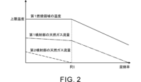
- FIG. 2 shows an example of the relationship between the temperature of the first combustion region, the natural gas flow rate of the first injection part, the natural gas flow rate of the second injection part, and the co-combustion rate in the combustion system according to the embodiment of the present disclosure.
- FIG. FIG. 3 is an example of the relationship between the temperature of the first combustion region, the natural gas flow rate of the first injection part, the natural gas flow rate of the second injection part, and the engine load in the combustion system according to the embodiment of the present disclosure.
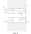
- FIG. FIG. 4 is a diagram illustrating an example of the configuration of the air injection section of the first burner according to the embodiment of the present disclosure.
- FIG. 1 is a schematic diagram showing the configuration of a combustion system 1 according to the present embodiment.
- the combustion system 1 is a gas turbine system that is an example of a combustion system that generates energy by burning fuel.
- the combustion system 1 includes a compressor 11a, a turbine 11b, a combustor 12, a first burner 13, a second burner 14, an ammonia supply source 15, and a natural gas supply source 16. , a temperature sensor 17, and a control device 18.
- the combustion system 1 also includes an engine E1 including a compressor 11a, a turbine 11b, and a combustor 12.
- Engine E1 is a gas turbine engine.
- the compressor 11a and the turbine 11b rotate as a unit.
- the compressor 11a and the turbine 11b are connected to each other by a shaft.
- the compressor 11a is provided in an intake flow path 101 connected to the combustor 12. Air supplied to the combustor 12 flows through the intake flow path 101 . An intake port (not shown) through which air is taken in from the outside is provided at the upstream end of the intake flow path 101. Air taken in from the intake port passes through the compressor 11a and is sent to the combustor 12. The compressor 11a compresses air and discharges it downstream.
- the turbine 11b is provided in an exhaust flow path 102 connected to the combustor 12. Exhaust gas discharged from the combustor 12 flows through the exhaust flow path 102 . Exhaust gas discharged from the combustor 12 passes through the turbine 11b and is sent to the downstream side of the turbine 11b in the exhaust flow path 102. The turbine 11b generates rotational power by being rotated by exhaust gas.
- a generator (not shown) is connected to the compressor 11a.
- the rotational power transmitted from the turbine 11b to the compressor 11a is used for power generation by the generator.
- the combustor 12 can be supplied with air, ammonia, and natural gas, respectively, as will be described later.
- Air compressed by a compressor 11a is supplied to the combustor 12 from an intake flow path 101.
- combustion is performed using at least one of ammonia and natural gas as fuel. That is, in the combustor 12, both ammonia and natural gas may be used as fuel, or only one of ammonia and natural gas may be used as fuel.
- Ammonia corresponds to the first fuel.
- Natural gas corresponds to an example of a second fuel that does not contain nitrogen atoms. However, the second fuel is not limited to natural gas.
- the second fuel may be, for example, natural gas, hydrogen or kerosene, or a combination thereof.
- Exhaust gas generated in the combustor 12 is discharged into the exhaust flow path 102.
- the combustor 12 includes a first combustion region 12a and a second combustion region 12b as combustion regions where fuel is combusted.
- the first combustion region 12a is located upstream of the second combustion region 12b in the gas flow direction within the combustor 12.
- the second combustion zone 12b is continuous to the first combustion zone 12a on the downstream side.
- the combustion area including the first combustion area 12a and the second combustion area 12b is, for example, a space defined by a cylindrical wall.
- the upstream side of the space corresponds to the first combustion area 12a, and the downstream side of the space corresponds to the second combustion area 12b.
- the exhaust flow path 102 described above is connected to the downstream end of the second combustion region 12b.
- the combustor 12 is provided with a first burner 13 and a second burner 14 as burners that inject fuel and air to each combustion region to form a flame.
- the first burner 13 faces the first combustion area 12a and injects fuel and air into the first combustion area 12a.
- the first burner 13 is provided at the upstream end of the first combustion region 12a.
- FIG. 1 shows an example in which the number of first burners 13 is one. However, the number of first burners 13 may be plural.
- the positional relationship of the plurality of first burners 13 is not limited.
- the plurality of first burners 13 may be provided at intervals in the circumferential direction of the first combustion region 12a.
- the first burner 13 includes an ammonia injection section 21, a natural gas injection section 22a, and an air injection section 23a. Each of these injection parts faces the first combustion area 12a. That is, fuel or air is injected from each of these injection parts into the first combustion region 12a.
- the ammonia injection section 21 includes a flow path that is supplied with ammonia and communicates with the first combustion region 12a. Ammonia supplied to the flow path is injected into the first combustion region 12a.
- the natural gas injection part 22a includes a flow path that is supplied with natural gas and communicates with the first combustion region 12a. The natural gas supplied to the flow path is injected into the first combustion region 12a.
- the air injection section 23a includes a flow path through which air is supplied and communicates with the first combustion region 12a. The air supplied to the flow path is injected into the first combustion area 12a.
- the second burner 14 faces the second combustion area 12b and injects fuel and air into the second combustion area 12b.
- the second burner 14 is provided on the side of the second combustion area 12b.
- FIG. 1 shows an example in which the number of second burners 14 is one. However, the number of second burners 14 may be plural.
- the positional relationship of the plurality of second burners 14 is not limited.
- the plurality of second burners 14 may be provided at intervals in the circumferential direction of the second combustion region 12b.
- the second burner 14 includes a natural gas injection section 22b and an air injection section 23b. Each of these injection parts faces the second combustion area 12b. That is, fuel or air is injected from each of these injection parts into the second combustion region 12b.
- the natural gas injection section 22b includes a flow path that is supplied with natural gas and communicates with the second combustion region 12b.
- the natural gas supplied to the flow path is injected into the second combustion region 12b.
- the air injection section 23b includes a flow path through which air is supplied and communicates with the second combustion region 12b. The air supplied to the flow path is injected into the second combustion region 12b.
- the natural gas injection part 22a of the first burner 13 is also referred to as the first injection part 22a.
- the natural gas injection part 22b of the second burner 14 is also referred to as a second injection part 22b.
- the compressor 11a compresses and discharges air. Air is supplied from the compressor 11a to the first burner 13 and the second burner 14 via the intake flow path 101.
- the intake flow path 101 includes a flow path 101a, a flow path 101b, and a flow path 101c.
- the compressor 11a is provided in the flow path 101a.
- the flow path 101a branches into a flow path 101b and a flow path 101c on the downstream side of the compressor 11a.
- the flow path 101b is connected to the air injection part 23a of the first burner 13. Therefore, air can be supplied from the compressor 11a to the air injection part 23a of the first burner 13 via the flow path 101a and the flow path 101b.
- the flow path 101c is connected to the air injection part 23b of the second burner 14. Therefore, air can be supplied from the compressor 11a to the air injection part 23b of the second burner 14 via the flow path 101a and the flow path 101c.
- the ammonia supply source 15 is, for example, an ammonia tank that stores ammonia.
- ammonia is stored in a liquid state in the ammonia tank.
- the ammonia supply source 15 is not limited to an ammonia tank.
- the ammonia supply source 15 may be a device that generates ammonia.
- the ammonia supply source 15 is connected to the ammonia injection section 21 of the first burner 13 via a flow path 103. Therefore, ammonia can be supplied from the ammonia supply source 15 to the ammonia injection section 21 of the first burner 13 via the flow path 103. Supply of ammonia from the ammonia supply source 15 to the first burner 13 is realized, for example, by a pump (not shown).
- a flow control valve 31 is provided in the flow path 103 .
- the flow rate control valve 31 adjusts the flow rate of ammonia sent to the first burner 13 through the flow path 103. Specifically, the amount of ammonia supplied to the first burner 13 is adjusted by adjusting the opening degree of the flow control valve 31.
- the natural gas supply source 16 is, for example, a natural gas tank that stores natural gas.
- natural gas is stored in a liquid state in a natural gas tank.
- the natural gas supply source 16 is not limited to a natural gas tank.
- the natural gas supply source 16 may be a device that generates natural gas.
- the natural gas supply source 16 is connected to the flow path 104.
- the flow path 104 branches into a flow path 105 and a flow path 106.
- the flow path 105 is connected to the natural gas injection part 22a of the first burner 13. Therefore, natural gas can be supplied from the natural gas supply source 16 to the natural gas injection part 22a of the first burner 13 via the flow path 104 and the flow path 105.
- the flow path 106 is connected to the natural gas injection part 22b of the second burner 14. Therefore, natural gas can be supplied from the natural gas supply source 16 to the natural gas injection part 22b of the second burner 14 via the flow path 104 and the flow path 106.
- Supply of ammonia from the natural gas supply source 16 to the first burner 13 and the second burner 14 is realized by, for example, a pump (not shown).
- a flow control valve 32 is provided in the flow path 105.
- the flow rate control valve 32 adjusts the flow rate of natural gas sent to the first burner 13 through the flow path 105. Specifically, the amount of natural gas supplied to the first burner 13 is adjusted by adjusting the opening degree of the flow rate control valve 32.
- a flow control valve 33 is provided in the flow path 106 .
- the flow rate control valve 33 adjusts the flow rate of natural gas sent to the second burner 14 through the flow path 106. Specifically, the amount of natural gas supplied to the second burner 14 is adjusted by adjusting the opening degree of the flow rate control valve 33.
- the temperature sensor 17 detects the temperature of the first combustion region 12a of the combustor 12.
- the temperature sensor 17 is provided, for example, on the side of the first combustion region 12a.
- the control device 18 includes a central processing unit (CPU), a ROM in which programs and the like are stored, and a RAM as a work area.
- the functions of the control device 18 are realized by a central processing unit, ROM, and the like.
- the control device 18 controls the operation of each device within the combustion system 1. For example, the control device 18 controls the operation of the flow control valves 31, 32, and 33, respectively. Further, the control device 18 acquires information from the temperature sensor 17.
- the control device 18 controls the flow rate of ammonia injected from the ammonia injection part 21 of the first burner 13. Specifically, the control device 18 controls the flow rate of ammonia injected from the injection part 21 of the first burner 13 by controlling the operation of the flow rate control valve 31 .
- the control device 18 controls the flow rate of natural gas injected from the first injection part 22a, which is the natural gas injection part of the first burner 13. Specifically, the control device 18 controls the flow rate of natural gas injected from the first injection part 22a of the first burner 13 by controlling the operation of the flow rate control valve 32.
- the control device 18 controls the flow rate of natural gas injected from the second injection part 22b, which is the natural gas injection part of the second burner 14. Specifically, the control device 18 controls the flow rate of natural gas injected from the second injection part 22b of the second burner 14 by controlling the operation of the flow rate control valve 33.
- the control device 18 controls the flow rate of ammonia injected from the injection part 21 of the first burner 13, the flow rate of natural gas injected from the first injection part 22a of the first burner 13, and the flow rate of the natural gas injected from the first injection part 22a of the first burner 13.
- the flow rate of natural gas injected from the fourteen second injection parts 22b can be individually controlled. Therefore, the control device 18 can control the ratio of the amount of ammonia supplied to the combustor 12 and the amount of natural gas supplied to the combustor 12. That is, the control device 18 can control the co-firing rate, which is the ratio of the calorific value of ammonia to the total calorific value of ammonia and natural gas in the combustor 12.
- the control device 18 controls the flow rate of natural gas injected from the first natural gas injection part 22a of the first burner 13 and the flow rate of natural gas injected from the second natural gas injection part 22b of the second burner 14.
- the natural gas flow rate ratio which is the ratio to the flow rate, can be adjusted.
- the second fuel is not limited to natural gas. Therefore, the natural gas flow rate ratio is an example of the second fuel flow rate ratio, which is the ratio between the flow rate of the second fuel injected from the first injection part 22a and the flow rate of the second fuel injected from the second injection part 22b. corresponds to
- the temperature of the flame formed in the first combustion region 12a becomes excessively high, there is a risk that devices such as the liner of the combustor 12 or the first burner 13 will be damaged.
- the flame temperature of the second fuel such as natural gas is higher than that of ammonia, when the co-firing rate is low, if natural gas is injected only from the first injection part 22a of the first burner 13, There is a possibility that the temperature of the flame formed in the first combustion region 12a becomes excessively high.
- the control device 18 controls the flow rate of natural gas injected from the first natural gas injection part 22a of the first burner 13 and the second injection of natural gas of the second burner 14.
- the natural gas flow rate ratio which is the ratio to the flow rate of natural gas injected from the section 22b, is adjusted. Therefore, without injecting all of the natural gas supplied to the combustor 12 from the first injection part 22a of the first burner 13, a part of the natural gas supplied to the combustor 12 is injected from the second injection part 22a of the second burner 14. It can be injected from the injection part 22b. Therefore, it is possible to prevent the temperature of the flame formed in the first combustion region 12a from becoming excessively high, and therefore damage to the device due to the flame can be suppressed.
- the control device 18 adjusts the natural gas flow rate ratio based on the temperature of the first combustion region 12a, for example.
- An example in which the natural gas flow rate ratio is adjusted based on the temperature of the first combustion region 12a will be described below.
- the control device 18 may adjust the natural gas flow rate ratio based on parameters other than the temperature of the first combustion region 12a.
- the control device 18 when the temperature of the first combustion region 12a is lower than the upper limit temperature, the control device 18 causes all of the natural gas supplied to the combustor 12 to be injected from the first injection part 22a of the first burner 13, and the second burner The natural gas flow rate ratio is adjusted so that natural gas is not injected from the 14 second injection parts 22b.
- the control device 18 controls a part of the natural gas supplied to the combustor 12 to be injected from the second injection part 22b of the second burner 14. Adjust the natural gas flow rate ratio so that The upper limit temperature can be set as appropriate, taking into consideration the heat resistance of each device near the first combustion region 12a.
- FIG. 2 is a diagram showing an example of the relationship between the temperature of the first combustion region 12a, the natural gas flow rate of the first injection part 22a, the natural gas flow rate of the second injection part 22b, and the co-combustion rate in the combustion system 1.
- the natural gas flow rate of the first injection part 22a means the flow rate of natural gas injected from the first injection part 22a of the first burner 13.
- the natural gas flow rate of the second injection part 22b means the flow rate of natural gas injected from the second injection part 22b of the second burner 14.
- the temperature of the first combustion region 12a, the natural gas flow rate of the first injection part 22a, and the natural gas flow rate of the second injection part 22b are shown by a solid line, a dashed line, and a broken line, respectively.
- the higher the co-combustion rate the higher the ratio of the total amount of ammonia supplied to the total amount of fuel supplied to the combustor 12.
- the lower the co-combustion rate the higher the ratio of the total amount of natural gas supplied to the total amount of fuel supplied to the combustor 12.
- the load on engine E1 is constant.
- the total calorific value of the fuel supplied to the combustor 12 is also approximately constant.
- the process in which the co-firing rate decreases from a high state corresponds to the process in which the co-firing rate decreases from a high state.
- the temperature of the first combustion region 12a is lower than the upper limit temperature. Therefore, all of the natural gas supplied to the combustor 12 is injected from the first injection part 22a of the first burner 13, and no natural gas is injected from the second injection part 22b of the second burner 14.
- the control device 18 adjusts the natural gas flow rate ratio so that the temperature of the first combustion region 12a is maintained at the upper limit temperature in a region where the co-combustion rate is lower than the value R1.
- the control device 18 controls the ratio of the natural gas flow rate of the second injection part 22b to the total flow rate of natural gas. Adjust the natural gas flow rate ratio so that it becomes higher. As a result, as shown in FIG. 2, in a region where the co-firing rate is lower than the value R1, as the co-firing rate decreases, the ratio of the natural gas flow rate of the second injection part 22b to the total flow rate of natural gas increases. Thereby, the temperature of the first combustion region 12a is maintained at the upper limit temperature. As shown in FIG.
- natural gas is injected from the second injection part 22b of the second burner 14 in a region where the temperature of the first combustion region 12a is lower than the upper limit temperature (that is, a region where the co-combustion rate is higher than the value R1). All of the natural gas supplied to the combustor 12 is injected from the first injection part 22a of the first burner 13. This prevents the temperature of the first combustion region 12a from decreasing excessively. Therefore, the stability of the flame in the first combustion region 12a is ensured.
- FIG. 3 shows an example of the relationship between the temperature of the first combustion region 12a, the natural gas flow rate of the first injection part 22a, the natural gas flow rate of the second injection part 22b, and the load of the engine E1 in the combustion system 1. It is a diagram.
- the temperature of the first combustion region 12a, the natural gas flow rate of the first injection section 22a, and the natural gas flow rate of the second injection section 22b are indicated by a solid line, a dashed line, and a broken line, respectively. has been done.
- the load on the engine E1 varies depending on, for example, the required amount of power generated by the generator connected to the compressor 11a.
- the control device 18 adjusts the natural gas flow rate ratio so that the temperature of the first combustion region 12a is maintained at the upper limit temperature in a region where the load of the engine E1 is greater than the value L1.
- the control device 18 controls the flow rate of natural gas in the second injection part 22b relative to the total flow rate of natural gas. Adjust the natural gas flow rate ratio so that the ratio becomes higher.
- the ratio of the natural gas flow rate of the second injection part 22b to the total flow rate of natural gas increases. Become. Thereby, the temperature of the first combustion region 12a is maintained at the upper limit temperature.
- the control device 18 adjusts the natural gas flow rate ratio based on the temperature of the first combustion region 12a. Thereby, it is possible to suppress the temperature of the flame formed in the first combustion region 12a from becoming excessively high. Specifically, when the co-combustion rate is low or when the load on the engine E1 is large, it is possible to suppress the temperature of the first combustion region 12a from exceeding the upper limit temperature. Therefore, damage to the device due to flame can be suppressed. Furthermore, it is possible to suppress the temperature of the first combustion region 12a from decreasing excessively. Specifically, when the co-combustion rate is high or when the load on the engine E1 is small, it is possible to suppress the temperature of the first combustion region 12a from decreasing excessively. Therefore, the stability of the flame in the first combustion region 12a is ensured.
- control device 18 may adjust the natural gas flow rate ratio based on parameters other than the temperature of the first combustion region 12a.
- the control device 18 may adjust the natural gas flow rate ratio based on the co-firing rate. For example, information about the co-firing rate that changes according to a preset schedule is input to the control device 18. The control device 18 can obtain the co-firing rate using this information. For example, when the co-combustion rate is higher than the value R1 in FIG. The natural gas flow rate ratio is adjusted so that natural gas is not injected from the second injection part 22b.
- control device 18 controls the control device 18 so that, for example, when the co-combustion rate is lower than the value R1 in FIG. Then, adjust the natural gas flow rate ratio. Specifically, when the co-firing rate is lower than the value R1 in FIG. 2, the control device 18 causes the ratio of the natural gas flow rate of the second injection part 22b to the total flow rate of natural gas to increase as the co-firing rate decreases. Adjust the natural gas flow ratio accordingly.
- the temperature of the first combustion area 12a is the upper limit temperature, similar to the case where the natural gas flow rate ratio is adjusted based on the temperature of the first combustion area 12a. Since it is possible to suppress the flame from exceeding the maximum value, it is possible to suppress damage to the device caused by the flame. Furthermore, since the temperature of the first combustion region 12a can be prevented from decreasing excessively, the stability of the flame in the first combustion region 12a is ensured.
- the control device 18 may adjust the natural gas flow rate ratio based on the load of the engine E1. For example, information on the load of the engine E1 that changes according to a preset schedule is input to the control device 18. The control device 18 can obtain the load of the engine E1 using the information. For example, when the load of the engine E1 is smaller than the value L1 in FIG. The natural gas flow rate ratio is adjusted so that natural gas is not injected from the second injection part 22b of the burner 14.
- control device 18 controls, for example, when the load of the engine E1 is larger than the value L1 in FIG. Adjust the natural gas flow rate ratio so that Specifically, when the load on the engine E1 is larger than the value L1 in FIG. 3, the control device 18 adjusts the natural gas flow rate of the second injection part 22b with respect to the total flow rate of natural gas as the load on the engine E1 increases. Adjust the natural gas flow rate ratio so that the ratio becomes higher.
- the temperature of the first combustion area 12a is Since it is possible to prevent the temperature from exceeding the upper limit temperature, damage to the device due to flames can be suppressed. Furthermore, since the temperature of the first combustion region 12a can be prevented from decreasing excessively, the stability of the flame in the first combustion region 12a is ensured.
- the control device 18 may adjust the natural gas flow rate ratio based on the total calorific value of ammonia and natural gas. For example, information on the load of the engine E1 that changes according to a preset schedule is input to the control device 18. Using this information, the control device 18 can obtain the total calorific value of ammonia and natural gas. The total calorific value has a correlation with the load of the engine E1. Therefore, for example, when the total calorific value is smaller than the threshold value, the control device 18 injects all the natural gas supplied to the combustor 12 from the first injection part 22a of the first burner 13 and The natural gas flow rate ratio is adjusted so that natural gas is not injected from the second injection part 22b.
- control device 18 controls the natural gas so that, for example, when the total calorific value is larger than the threshold value, a part of the natural gas supplied to the combustor 12 is injected from the second injection part 22b of the second burner 14. Adjust the flow ratio. Specifically, when the total calorific value is larger than the threshold value, the control device 18 controls such that as the load of the total calorific value increases, the ratio of the natural gas flow rate of the second injection part 22b to the total natural gas flow rate increases. Then, adjust the natural gas flow rate ratio.
- the temperature of the first combustion region 12a, the co-combustion rate, the load of the engine E1, and the total calorific value have been described as parameters used to adjust the natural gas flow rate ratio.
- a plurality of types of parameters among these parameters may be used in combination as parameters used to adjust the natural gas flow rate ratio.
- parameters other than those described above may be used as parameters used to adjust the natural gas flow rate ratio.
- the air injection part 23a of the first burner 13 be devised as described below.
- such a device will be explained with reference to FIG. 4.
- FIG. 4 is a diagram showing an example of the configuration of the air injection part 23a of the first burner 13.
- the first burner 13 includes a rotating portion 24.
- the swirling section 24 swirls the air injected from the air injection section 23a of the first burner 13.
- the rotating section 24 includes a shaft 24a and a rotating blade 24b.
- the shaft 24a extends, for example, on the central axis of the air flow path in the injection section 23a.
- the swirler blade 24b extends radially outward from the outer peripheral surface of the shaft 24a.
- a plurality of swirl vanes 24b are provided at intervals in the circumferential direction of the shaft 24a.
- a swirling force is applied to the air flowing through the injection portion 23a.
- the swirling section 24 is not limited to the example shown in FIG. 4 as long as it can swirl the air injected from the air injection section 23a of the first burner 13.
- the first burner 13 includes the swirling part 24 that swirls the air injected from the air injection part 23a of the first burner 13. Thereby, the stability of the flame in the first combustion region 12a is ensured.
- the rotating portion 24 may be omitted from the first burner 13.
- the rotational power transmitted from the turbine 11b to the compressor 11a is used as energy to drive the generator.
- the rotational power transmitted from the turbine 11b to the compressor 11a may be used for other purposes, such as for driving a moving body such as a ship.
- ammonia injection section 21 and the natural gas injection section 22a are separate injection sections in the first burner 13.
- ammonia and natural gas may be mixed in advance and injected into the first combustion region 12a from one injection part.
- one injection part also functions as an ammonia injection part and also functions as a natural gas injection part.
- ammonia and air may be mixed in advance and injected into the first combustion region 12a from one injection part.
- ammonia, natural gas, and air may be mixed in advance and injected into the first combustion region 12a from one injection part.
- natural gas and air may be mixed in advance and injected from one injection part into the second combustion area 12b.
- the present disclosure contributes to suppressing damage to equipment caused by flames in combustion systems such as gas turbine systems, so for example, the present disclosure contributes to reducing damage to equipment caused by flames in combustion systems such as gas turbine systems. can contribute to ensuring access to
- Combustion system 12 Combustor 12a: First combustion zone 12b: Second combustion zone 13: First burner 14: Second burner 18: Control device 21: Ammonia injection section 22a: Natural gas injection section (first Injection part) 22b: Natural gas injection part (second injection part) 23a: Air injection part 24: Swivel part E1: Engine
Landscapes
- Engineering & Computer Science (AREA)
- Chemical & Material Sciences (AREA)
- Combustion & Propulsion (AREA)
- Mechanical Engineering (AREA)
- General Engineering & Computer Science (AREA)
Priority Applications (4)
| Application Number | Priority Date | Filing Date | Title |
|---|---|---|---|
| EP22933643.3A EP4477950A4 (en) | 2022-03-25 | 2022-12-07 | COMBUSTION SYSTEM |
| JP2024509750A JP7786558B2 (ja) | 2022-03-25 | 2022-12-07 | 燃焼システム |
| CN202280093498.3A CN118871717A (zh) | 2022-03-25 | 2022-12-07 | 燃烧系统 |
| US18/886,005 US12553394B2 (en) | 2022-03-25 | 2024-09-16 | Gas turbine combustor having a first combustion zone receiving multiple fuels and a second combustion zone receiving a fuel not containing nitrogen atoms |
Applications Claiming Priority (2)
| Application Number | Priority Date | Filing Date | Title |
|---|---|---|---|
| JP2022-049708 | 2022-03-25 | ||
| JP2022049708 | 2022-03-25 |
Related Child Applications (1)
| Application Number | Title | Priority Date | Filing Date |
|---|---|---|---|
| US18/886,005 Continuation US12553394B2 (en) | 2022-03-25 | 2024-09-16 | Gas turbine combustor having a first combustion zone receiving multiple fuels and a second combustion zone receiving a fuel not containing nitrogen atoms |
Publications (1)
| Publication Number | Publication Date |
|---|---|
| WO2023181513A1 true WO2023181513A1 (ja) | 2023-09-28 |
Family
ID=88100487
Family Applications (1)
| Application Number | Title | Priority Date | Filing Date |
|---|---|---|---|
| PCT/JP2022/045091 Ceased WO2023181513A1 (ja) | 2022-03-25 | 2022-12-07 | 燃焼システム |
Country Status (5)
| Country | Link |
|---|---|
| US (1) | US12553394B2 (https=) |
| EP (1) | EP4477950A4 (https=) |
| JP (1) | JP7786558B2 (https=) |
| CN (1) | CN118871717A (https=) |
| WO (1) | WO2023181513A1 (https=) |
Citations (5)
| Publication number | Priority date | Publication date | Assignee | Title |
|---|---|---|---|---|
| JP2010019195A (ja) * | 2008-07-11 | 2010-01-28 | Toyota Motor Corp | ガスタービンの運転制御装置 |
| JP2012141078A (ja) * | 2010-12-28 | 2012-07-26 | Kawasaki Heavy Ind Ltd | 燃焼装置、及び該燃焼装置の燃焼制御方法 |
| JP2016003852A (ja) * | 2015-02-13 | 2016-01-12 | 川崎重工業株式会社 | マルチ燃料対応のガスタービン燃焼器 |
| JP2016191507A (ja) | 2015-03-31 | 2016-11-10 | 株式会社Ihi | 燃焼装置、ガスタービン及び発電装置 |
| JP2022049708A (ja) | 2018-12-26 | 2022-03-30 | シャープ株式会社 | 生成装置、3次元データ送信装置、及び3次元データ再生装置 |
Family Cites Families (29)
| Publication number | Priority date | Publication date | Assignee | Title |
|---|---|---|---|---|
| JPS6179914A (ja) * | 1984-09-28 | 1986-04-23 | Hitachi Ltd | 予混合燃焼器 |
| JP3658415B2 (ja) * | 1993-12-28 | 2005-06-08 | 株式会社 日立インダストリイズ | ガスタービン装置 |
| JP3012166B2 (ja) | 1995-02-01 | 2000-02-21 | 川崎重工業株式会社 | ガスタービン燃焼システム |
| US6047550A (en) | 1996-05-02 | 2000-04-11 | General Electric Co. | Premixing dry low NOx emissions combustor with lean direct injection of gas fuel |
| US20010049932A1 (en) | 1996-05-02 | 2001-12-13 | Beebe Kenneth W. | Premixing dry low NOx emissions combustor with lean direct injection of gas fuel |
| JP4745767B2 (ja) * | 2005-09-08 | 2011-08-10 | 三菱重工業株式会社 | 燃料流量制御装置及び発電システム並びに燃料流量制御方法 |
| GB2434437B (en) * | 2006-01-19 | 2011-01-26 | Siemens Ag | Improvements in or relating to combustion apparatus |
| US20100095649A1 (en) * | 2008-10-20 | 2010-04-22 | General Electric Company | Staged combustion systems and methods |
| US8701382B2 (en) * | 2009-01-07 | 2014-04-22 | General Electric Company | Late lean injection with expanded fuel flexibility |
| JP5075900B2 (ja) * | 2009-09-30 | 2012-11-21 | 株式会社日立製作所 | 水素含有燃料対応燃焼器および、その低NOx運転方法 |
| JP6033887B2 (ja) * | 2012-12-13 | 2016-11-30 | 川崎重工業株式会社 | マルチ燃料対応のガスタービン燃焼器 |
| US20150118014A1 (en) * | 2013-10-29 | 2015-04-30 | General Electric Company | Setting Gas Turbine Firing to Maintain Metal Surface Temperatures |
| US9845732B2 (en) * | 2014-05-28 | 2017-12-19 | General Electric Company | Systems and methods for variation of injectors for coherence reduction in combustion system |
| EP2955445B1 (en) * | 2014-06-12 | 2019-11-27 | Kawasaki Jukogyo Kabushiki Kaisha | Multifuel gas turbine combustor |
| JP6463947B2 (ja) * | 2014-11-05 | 2019-02-06 | 川崎重工業株式会社 | バーナ、燃焼器、及びガスタービン |
| JP2016109309A (ja) * | 2014-12-02 | 2016-06-20 | 川崎重工業株式会社 | ガスタービン用燃焼器、及びガスタービン |
| JP6637905B2 (ja) * | 2014-12-25 | 2020-01-29 | 川崎重工業株式会社 | バーナ、燃焼器、及びガスタービン |
| US10480792B2 (en) * | 2015-03-06 | 2019-11-19 | General Electric Company | Fuel staging in a gas turbine engine |
| JP6866570B2 (ja) * | 2016-03-30 | 2021-04-28 | 株式会社Ihi | 燃焼装置及びガスタービン |
| US10502426B2 (en) * | 2017-05-12 | 2019-12-10 | General Electric Company | Dual fuel injectors and methods of use in gas turbine combustor |
| JP6906381B2 (ja) | 2017-07-03 | 2021-07-21 | 株式会社東芝 | 燃焼装置およびガスタービン |
| EP3450850A1 (en) * | 2017-09-05 | 2019-03-06 | Siemens Aktiengesellschaft | A gas turbine combustor assembly with a trapped vortex cavity |
| JP6945468B2 (ja) * | 2018-02-06 | 2021-10-06 | 三菱パワー株式会社 | ガスタービン燃焼器、ガスタービン及びガスタービン燃焼器の制御方法 |
| US11287134B2 (en) | 2019-12-31 | 2022-03-29 | General Electric Company | Combustor with dual pressure premixing nozzles |
| JP7478597B2 (ja) * | 2020-06-08 | 2024-05-07 | 三菱重工業株式会社 | ガスタービンの制御装置および方法並びにガスタービン |
| TWI880740B (zh) * | 2021-09-30 | 2025-04-11 | 日商三菱重工業股份有限公司 | 發電設備 |
| US11566790B1 (en) * | 2021-10-28 | 2023-01-31 | General Electric Company | Methods of operating a turbomachine combustor on hydrogen |
| CN114353121B (zh) * | 2022-01-18 | 2022-12-20 | 上海交通大学 | 一种用于燃气轮机的多喷嘴燃料注入方法 |
| US20250067436A1 (en) * | 2023-08-25 | 2025-02-27 | Ge Infrastructure Technology Llc | Ammonia combustor |
-
2022
- 2022-12-07 JP JP2024509750A patent/JP7786558B2/ja active Active
- 2022-12-07 EP EP22933643.3A patent/EP4477950A4/en active Pending
- 2022-12-07 CN CN202280093498.3A patent/CN118871717A/zh active Pending
- 2022-12-07 WO PCT/JP2022/045091 patent/WO2023181513A1/ja not_active Ceased
-
2024
- 2024-09-16 US US18/886,005 patent/US12553394B2/en active Active
Patent Citations (5)
| Publication number | Priority date | Publication date | Assignee | Title |
|---|---|---|---|---|
| JP2010019195A (ja) * | 2008-07-11 | 2010-01-28 | Toyota Motor Corp | ガスタービンの運転制御装置 |
| JP2012141078A (ja) * | 2010-12-28 | 2012-07-26 | Kawasaki Heavy Ind Ltd | 燃焼装置、及び該燃焼装置の燃焼制御方法 |
| JP2016003852A (ja) * | 2015-02-13 | 2016-01-12 | 川崎重工業株式会社 | マルチ燃料対応のガスタービン燃焼器 |
| JP2016191507A (ja) | 2015-03-31 | 2016-11-10 | 株式会社Ihi | 燃焼装置、ガスタービン及び発電装置 |
| JP2022049708A (ja) | 2018-12-26 | 2022-03-30 | シャープ株式会社 | 生成装置、3次元データ送信装置、及び3次元データ再生装置 |
Non-Patent Citations (1)
| Title |
|---|
| See also references of EP4477950A4 |
Also Published As
| Publication number | Publication date |
|---|---|
| CN118871717A (zh) | 2024-10-29 |
| EP4477950A4 (en) | 2026-02-11 |
| JP7786558B2 (ja) | 2025-12-16 |
| EP4477950A1 (en) | 2024-12-18 |
| US20250003594A1 (en) | 2025-01-02 |
| JPWO2023181513A1 (https=) | 2023-09-28 |
| US12553394B2 (en) | 2026-02-17 |
Similar Documents
| Publication | Publication Date | Title |
|---|---|---|
| KR102218321B1 (ko) | 가스 터빈 연소기 | |
| US6983605B1 (en) | Methods and apparatus for reducing gas turbine engine emissions | |
| JP4958709B2 (ja) | 燃焼器音響作用の低減を促進する装置 | |
| US20150275755A1 (en) | Multi-fuel-capable gas turbine combustor | |
| US12404813B2 (en) | Control method for gas turbine combustor and control device for gas turbine combustor | |
| CN105737203A (zh) | 一种旋流器及采用其的预混燃烧器 | |
| EP4256235B1 (en) | Method of operating a combustor for a gas turbine | |
| WO2016056180A1 (ja) | ガスタービンエンジンの燃焼器及びその運転方法 | |
| WO2023181513A1 (ja) | 燃焼システム | |
| JP7833182B2 (ja) | 水素燃焼器、水素燃焼器システム、ジェットエンジン、及び発電装置 | |
| WO2024122143A1 (ja) | 燃焼装置 | |
| JPH09152105A (ja) | ガスタービン用低NOxバーナ | |
| JP7847232B2 (ja) | ガスタービンの運転方法 | |
| KR102821855B1 (ko) | 복합 연소 버너 및 이를 포함하는 연소 장치 | |
| JP7731507B2 (ja) | ガスタービン及びガスタービン設備 | |
| JP4386195B2 (ja) | 二流体サイクル用低NOx燃焼器とその運転方法 | |
| EP4116554B1 (en) | Method for operating a gas turbine and method for retrofitting a gas turbine | |
| JP7589813B2 (ja) | ガスタービンシステム | |
| WO2025164755A1 (ja) | ガスタービンの制御装置および制御方法 | |
| JP2019515243A (ja) | 排気を減らすための選択的燃焼器制御の方法 | |
| WO2024195437A1 (ja) | ガスタービン制御装置、ガスタービン制御方法、及び、ガスタービン制御プログラム | |
| KR20260025867A (ko) | 연소 장치 및 가스 터빈 시스템 | |
| WO2024116963A1 (ja) | ガスタービンの運転方法 | |
| WO2024202455A1 (ja) | ガスタービン制御装置 | |
| CN114877372A (zh) | 燃气涡轮发动机的燃烧器 |
Legal Events
| Date | Code | Title | Description |
|---|---|---|---|
| 121 | Ep: the epo has been informed by wipo that ep was designated in this application |
Ref document number: 22933643 Country of ref document: EP Kind code of ref document: A1 |
|
| ENP | Entry into the national phase |
Ref document number: 2024509750 Country of ref document: JP Kind code of ref document: A |
|
| WWE | Wipo information: entry into national phase |
Ref document number: 202280093498.3 Country of ref document: CN Ref document number: 2022933643 Country of ref document: EP |
|
| ENP | Entry into the national phase |
Ref document number: 2022933643 Country of ref document: EP Effective date: 20240911 |
|
| NENP | Non-entry into the national phase |
Ref country code: DE |