WO2023181440A1 - 使い捨て吸収性物品 - Google Patents
使い捨て吸収性物品 Download PDFInfo
- Publication number
- WO2023181440A1 WO2023181440A1 PCT/JP2022/028975 JP2022028975W WO2023181440A1 WO 2023181440 A1 WO2023181440 A1 WO 2023181440A1 JP 2022028975 W JP2022028975 W JP 2022028975W WO 2023181440 A1 WO2023181440 A1 WO 2023181440A1
- Authority
- WO
- WIPO (PCT)
- Prior art keywords
- region
- width direction
- sheet
- absorbent article
- elastic member
- Prior art date
Links
- 230000002745 absorbent Effects 0.000 title claims abstract description 131
- 239000002250 absorbent Substances 0.000 title claims abstract description 131
- 238000005304 joining Methods 0.000 claims abstract description 105
- 230000006835 compression Effects 0.000 claims abstract description 50
- 238000007906 compression Methods 0.000 claims abstract description 50
- 238000003466 welding Methods 0.000 claims description 20
- 238000004049 embossing Methods 0.000 description 19
- 239000004745 nonwoven fabric Substances 0.000 description 19
- 239000000835 fiber Substances 0.000 description 10
- 239000000853 adhesive Substances 0.000 description 7
- 230000001070 adhesive effect Effects 0.000 description 7
- 239000002985 plastic film Substances 0.000 description 7
- 229920006255 plastic film Polymers 0.000 description 7
- 239000004831 Hot glue Substances 0.000 description 6
- 239000007788 liquid Substances 0.000 description 5
- 239000000463 material Substances 0.000 description 5
- 238000000034 method Methods 0.000 description 5
- 230000035699 permeability Effects 0.000 description 5
- 239000005871 repellent Substances 0.000 description 5
- 230000008602 contraction Effects 0.000 description 4
- 238000005520 cutting process Methods 0.000 description 3
- 230000002209 hydrophobic effect Effects 0.000 description 3
- 230000008901 benefit Effects 0.000 description 2
- 239000004744 fabric Substances 0.000 description 2
- 210000004013 groin Anatomy 0.000 description 2
- 239000004750 melt-blown nonwoven Substances 0.000 description 2
- 238000012986 modification Methods 0.000 description 2
- 230000004048 modification Effects 0.000 description 2
- 230000002940 repellent Effects 0.000 description 2
- 229920000247 superabsorbent polymer Polymers 0.000 description 2
- 210000002700 urine Anatomy 0.000 description 2
- XLYOFNOQVPJJNP-UHFFFAOYSA-N water Substances O XLYOFNOQVPJJNP-UHFFFAOYSA-N 0.000 description 2
- 229920000742 Cotton Polymers 0.000 description 1
- 244000043261 Hevea brasiliensis Species 0.000 description 1
- 229920000297 Rayon Polymers 0.000 description 1
- 229920002678 cellulose Polymers 0.000 description 1
- 239000001913 cellulose Substances 0.000 description 1
- 239000000470 constituent Substances 0.000 description 1
- 238000002955 isolation Methods 0.000 description 1
- 238000003475 lamination Methods 0.000 description 1
- 229920003052 natural elastomer Polymers 0.000 description 1
- 229920001194 natural rubber Polymers 0.000 description 1
- 230000000474 nursing effect Effects 0.000 description 1
- 229920002635 polyurethane Polymers 0.000 description 1
- 239000004814 polyurethane Substances 0.000 description 1
- 229920006264 polyurethane film Polymers 0.000 description 1
- 238000003825 pressing Methods 0.000 description 1
- 239000002964 rayon Substances 0.000 description 1
- 230000001568 sexual effect Effects 0.000 description 1
- 229920002994 synthetic fiber Polymers 0.000 description 1
- 239000012209 synthetic fiber Substances 0.000 description 1
- 239000002699 waste material Substances 0.000 description 1
Images


Classifications
-
- A—HUMAN NECESSITIES
- A61—MEDICAL OR VETERINARY SCIENCE; HYGIENE
- A61F—FILTERS IMPLANTABLE INTO BLOOD VESSELS; PROSTHESES; DEVICES PROVIDING PATENCY TO, OR PREVENTING COLLAPSING OF, TUBULAR STRUCTURES OF THE BODY, e.g. STENTS; ORTHOPAEDIC, NURSING OR CONTRACEPTIVE DEVICES; FOMENTATION; TREATMENT OR PROTECTION OF EYES OR EARS; BANDAGES, DRESSINGS OR ABSORBENT PADS; FIRST-AID KITS
- A61F13/00—Bandages or dressings; Absorbent pads
- A61F13/15—Absorbent pads, e.g. sanitary towels, swabs or tampons for external or internal application to the body; Supporting or fastening means therefor; Tampon applicators
- A61F13/45—Absorbent pads, e.g. sanitary towels, swabs or tampons for external or internal application to the body; Supporting or fastening means therefor; Tampon applicators characterised by the shape
- A61F13/47—Sanitary towels, incontinence pads or napkins
- A61F13/475—Sanitary towels, incontinence pads or napkins characterised by edge leakage prevention means
-
- A—HUMAN NECESSITIES
- A61—MEDICAL OR VETERINARY SCIENCE; HYGIENE
- A61F—FILTERS IMPLANTABLE INTO BLOOD VESSELS; PROSTHESES; DEVICES PROVIDING PATENCY TO, OR PREVENTING COLLAPSING OF, TUBULAR STRUCTURES OF THE BODY, e.g. STENTS; ORTHOPAEDIC, NURSING OR CONTRACEPTIVE DEVICES; FOMENTATION; TREATMENT OR PROTECTION OF EYES OR EARS; BANDAGES, DRESSINGS OR ABSORBENT PADS; FIRST-AID KITS
- A61F13/00—Bandages or dressings; Absorbent pads
- A61F13/15—Absorbent pads, e.g. sanitary towels, swabs or tampons for external or internal application to the body; Supporting or fastening means therefor; Tampon applicators
- A61F13/45—Absorbent pads, e.g. sanitary towels, swabs or tampons for external or internal application to the body; Supporting or fastening means therefor; Tampon applicators characterised by the shape
- A61F13/49—Absorbent articles specially adapted to be worn around the waist, e.g. diapers
- A61F13/494—Absorbent articles specially adapted to be worn around the waist, e.g. diapers characterised by edge leakage prevention means
Definitions
- the present invention relates to disposable absorbent articles that receive waste from the wearer.
- JP 2008-289622A discloses a sanitary napkin in which side sheets are arranged to cover both sides of a top sheet, in which the top sheet and the side sheets are joined at an embossed portion extending in the front-rear direction. have been disclosed.
- the embossed portion is wide at the front and rear of the sanitary napkin, and narrow at the center.
- JP-A No. 2003-24384 discloses a structure in which the joint between the top sheet and the leak-proof part is located at the center and outside in the width direction of the sanitary napkin from the front and rear sides.
- the area where the emboss is formed is relatively hard. Therefore, when the embossed areas are located far apart from each other in the front and back of the absorbent article, as in Document 1, discomfort occurs on the left and right sides of the front and back of the absorbent article.
- a gather sheet to prevent leakage is widely present on the ventral and dorsal sides when worn, such as in disposable diapers or disposable auxiliary absorbent devices placed inside diapers or diaper-like covers, the gathers Attempting to fix the seat to the center seat using embossing (that is, by welding) is likely to cause discomfort.
- Document 1 also does not take into consideration the discomfort that occurs on the left and right sides of the front and rear portions of the absorbent article when a gathered sheet having an elastic member is provided.
- the embossed portion exists in a substantially straight line in the vertical direction and does not have a structure in which the gathers are made to stand up significantly.
- the present invention aims to improve the feeling of wearing in an absorbent article in which a gather sheet is joined to a center sheet by welding accompanied by pressure.
- Aspect 1 of the present invention is a disposable absorbent article that receives excrement from a wearer, and includes a top sheet, a back sheet, and an absorbent core located between the top sheet and the back sheet.
- the top sheet includes a center sheet and a pair of gathered sheets fixed to the center sheet at a distance from a center line facing the vertical direction on both sides in a width direction perpendicular to the vertical direction
- Each of the gather sheets includes the longitudinally long side sheet and an elastic member fixed to the widthwise inner region of the side sheet and extending in the longitudinal direction, and the center sheet and the pair of gathers
- the sheets are joined by welding with pressure in a compression joint region, and the compression joint region between the center sheet and each gather sheet is located in the center range in the longitudinal direction, and is separated from the elastic member.
- the center joint region is spaced outwardly in the width direction, and the end joint region is located in a range of both ends in the longitudinal direction and does not overlap with the elastic member, and the end joint region is arranged in the width direction.
- the elastic member includes an outer joint region located outside the elastic member, and an inner joint region located inside the elastic member in the width direction.
- the feeling of wearing can be improved in an absorbent article in which a gather sheet is joined to a center sheet by welding accompanied by pressure.
- a second aspect of the present invention is the disposable absorbent article of aspect 1, in which the central joint region and the outer joint region are continuous in the longitudinal direction.
- a third aspect of the present invention is the disposable absorbent article according to aspect 1 or 2, wherein the outer edge of the end joining region in the width direction is wider than the inner edge of the central joining region in the width direction. located inside.
- Aspect 4 of the present invention is the disposable absorbent article according to Aspect 1 or 2 (which may be any one of Aspects 1 to 3), in which the compression bonding region has a large number of dot-like bonding elements. , and the existence ratio of the joining elements between the outer edge and the inner edge in the width direction of the end joining region is the set of the joining elements between the outer edge and the inner edge in the width direction of the central joining region smaller than the element's proportion.
- Aspect 5 of the present invention is the disposable absorbent article of Aspect 1 or 2 (which may be any one of Aspects 1 to 4), comprising a plurality of elastic members including the elastic member, Among the plurality of elastic members, the elastic member located innermost in the width direction is located inside the inner joining region in the width direction.
- a sixth aspect of the present invention is the disposable absorbent article according to the fifth aspect, in which an elastic member located second from the inside in the width direction among the plurality of elastic members is connected to the inner joint region in the width direction. Located between the outer junction area.
- Aspect 7 of the present invention is the disposable absorbent article of Aspect 1 or 2 (which may be any one of Aspects 1 to 6), wherein the outer joint region includes a plurality of longitudinally extending Contains linear areas.
- Aspect 8 of the present invention is the disposable absorbent article according to Aspect 1 or 2 (which may be any one of Aspects 1 to 7), wherein the compression bonding region is arranged in the longitudinal direction of the topsheet.
- the maximum value of the total length of compression joints in the width direction of the compression joint region is 1.25 times or more and 4 times or less of the minimum value.
- Aspect 9 of the present invention is the disposable absorbent article according to Aspect 1 or 2 (which may be any one of Aspects 1 to 8), wherein the disposable absorbent article of Aspect 1 or 2 (which may be any one of Aspects 1 to 8) is provided, wherein the The edge is a discontinuous line, the edge slopes toward the center in the vertical direction as it goes outward in the width direction, and the edge is added to the outside or inside of the width direction in the range where the edge is interrupted. There is a bonded area.
- Aspect 10 of the present invention is the disposable absorbent article of Aspect 1 or 2 (which may be any one of Aspects 1 to 9), which is disposed within a diaper or a diaper-like cover.
- FIG. 2 is a plan view showing the configuration of an absorbent article.
- FIG. 2 is a perspective view showing one of the free states of the absorbent article. It is a sectional view of an absorbent article. It is a sectional view of an absorbent article.
- FIG. 3 is an enlarged cross-sectional view showing the vicinity of the gather sheet.
- FIG. 3 is an enlarged view showing the vicinity of the boundary between the central joint region and the end joint regions.
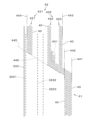
- FIG. 1 is a plan view showing the configuration of a disposable absorbent article 1 (hereinafter simply referred to as "absorbent article 1") according to one embodiment of the present invention.
- the absorbent article 1 is shown in a flat state.
- the absorbent article 1 is an auxiliary absorbent device that is placed inside an exterior article worn by a wearer (ie, on the wearer's side) to receive excrement from the wearer.
- Exterior articles include disposable diapers, non-disposable diapers, diaper-like covers, and the like.
- the absorbent article 1 is used, for example, by a person receiving care at a hospital or a nursing care facility.
- the surface of the absorbent article 1 that comes into contact with the wearer is shown in the front.
- the vertical direction in FIG. 1 will be referred to as the "vertical direction,” and the horizontal direction perpendicular to the vertical direction will be referred to as the “width direction.”
- the absorbent article 1 is bilaterally symmetrical, and in FIG. 1, the reference numeral 11 is attached to the center line facing in the longitudinal direction.
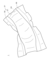
- FIG. 2 is a perspective view showing one of the free states of the absorbent article 1.
- the absorbent article 1 includes an elastic member, and the entire absorbent article 1 is in a curved state due to contraction of the elastic member.
- FIG. 3 is a cross-sectional view of the absorbent article 1 taken along a plane perpendicular to the longitudinal direction at the position III-III shown in FIG.
- FIG. 2 the gathers of the gather sheet, which will be described later, stand up due to the contraction force of the elastic member, so FIG. 3 depicts a state in which the gathers stand up.
- FIG. 4 is a cross-sectional view of the absorbent article 1 taken along a plane perpendicular to the longitudinal direction at the position IV-IV shown in FIG.
- the absorbent article 1 includes a top sheet 21, an absorbent core 22, and a back sheet 23.
- Absorbent core 22 is located between topsheet 21 and backsheet 23.
- the top sheet 21 includes a center sheet 31 and a pair of gathered sheets 32.
- the pair of gathered sheets 32 are fixed on both sides of the center sheet 31 (that is, at positions spaced apart from each other in the width direction) and extend in the vertical direction.
- Each gather sheet 32 exists over the entire length of the center sheet 31 in the vertical direction. In other words, the length of each gather sheet 32 in the longitudinal direction is substantially the same as the length of the absorbent article 1 in the longitudinal direction.
- the gathers which are the inner portions of the pair of gather sheets 32 in the width direction, stand up toward the wearer when the absorbent article 1 is worn.
- the upper part and the lower part in FIG. 1 are the front part and the rear part which are in contact with the wearer's ventral and dorsal skin, respectively.
- the part of the absorbent article 1 that is continuous from the front part and the rear part between the front part and the rear part is the central part facing the wearer's crotch region.
- the boundary between the front part and the central part and the boundary between the rear part and the central part do not need to be clearly defined.
- a front part, a center part, and a rear part are arranged in order in the longitudinal direction. In the example shown in FIG.
- the absorbent article 1 has a substantially rectangular shape in a plan view, and the width in the width direction of the front part, center part, and rear part (i.e., the width in the left and right direction when worn; hereinafter simply referred to as (also referred to as "width") are substantially the same.
- the width of the absorbent article 1 is substantially constant over the entire length in the vertical direction.
- FIGS. 3 and 4 described above are cross-sectional views of the absorbent article 1 in the central part and the front part, respectively.
- the cross section of the rear part of the absorbent article 1 is substantially similar to the cross section of the front part shown in FIG.
- the width of the absorbent article 1 does not need to be constant; for example, the width of the rear part may be larger than the width of the front part.
- the absorbent core 22 is sandwiched between the top sheet 21 and the back sheet 23.
- the top sheet 21 and the back sheet 23 are joined around the absorbent core 22 using an adhesive.
- the outline of the absorbent core 22 is drawn with thin broken lines.
- the absorbent article 1 is drawn larger than it actually is in the thickness direction (that is, the vertical direction in FIGS. 3 and 4).
- the constituent elements of the absorbent article 1 that are in contact with each other or are joined are depicted spaced apart appropriately in the thickness direction.
- the center sheet 31 of the top sheet 21 quickly captures moisture from the wearer's excrement and transfers it to the absorbent core 22.
- the absorbent core 22 absorbs moisture that has passed through the center sheet 31 and quickly fixes it.
- the backsheet 23 mainly prevents water, etc. of excrement that has passed through the center sheet 31 and the absorbent core 22 and reached the backsheet 23 from seeping out to the outside of the absorbent article 1.
- the absorbent core 22 is in contact with the center sheet 31 and the back sheet 23, but a mount (for example, tissue paper) may be placed between the absorbent core 22 and the center sheet 31.
- a mount may be placed between the sexual core 22 and the backsheet 23.
- the absorbent core 22 may be wrapped with another sheet, or the absorbent core 22 may be a plurality of superimposed absorbent cores. That is, various known structures may be employed for the absorbent core 22 and its surrounding structure.
- the length of the top sheet 21 and the back sheet 23 in the vertical direction is longer than the length of the absorbent core 22.
- the width of the top sheet 21 and the back sheet 23 in the width direction is larger than the width of the absorbent core 22.
- Both side portions of the top sheet 21 (that is, portions on both sides in the width direction) are joined to both side portions of the back sheet 23 over the entire length, either directly or indirectly via an intervening material.
- the width of the center sheet 31 may be smaller than the width of the back sheet 23, and in this case, the outer end of the gathered sheet 32 in the width direction may be joined to the back sheet 23.
- the longitudinal ends of the top sheet 21 and the back sheets 23 are directly or indirectly joined.
- top sheet 21 and the back sheet 23 are joined over the entire circumference of the absorbent core 22, so that the entire absorbent core 22 is surrounded by the top sheet 21 and the back sheet 23.
- a hot melt adhesive is used to join the top sheet 21 and the back sheet 23.
- the top sheet 21 and the back sheet 23 may be joined by various methods other than hot melt adhesive.
- the center sheet 31 may be, for example, a liquid-permeable nonwoven fabric (point bond nonwoven fabric, air-through nonwoven fabric, spunbond nonwoven fabrics, etc.) are used. Note that as the center sheet 31, a nonwoven fabric (for example, a spunlace nonwoven fabric) formed of hydrophilic fibers such as cellulose, rayon, and cotton may be used.
- a nonwoven fabric for example, a spunlace nonwoven fabric formed of hydrophilic fibers such as cellulose, rayon, and cotton may be used.
- the back sheet 23 preferably has a laminated structure in which a plurality of sheets are laminated.
- the backsheet 23 has a structure in which a liquid-repellent or liquid-impermeable nonwoven fabric or a nonwoven fabric is laminated on a plastic film. If the backsheet 23 includes a plastic film, the plastic film is placed opposite the absorbent core 22.
- the plastic film preferably has moisture permeability (breathability). Thereby, the water resistance of the backsheet 23 can be improved, and the absorbent article 1 can be prevented from getting stuffy, thereby improving the wearer's comfort.
- a liquid-repellent or liquid-impermeable nonwoven fabric is used as the nonwoven fabric laminated on the plastic film.
- the nonwoven fabric is, for example, a spunbond nonwoven fabric, a meltblown nonwoven fabric, or an SMS (spunbond/meltblown/spunbond) nonwoven fabric formed of hydrophobic fibers, and is subjected to a liquid repellent treatment if necessary.
- the absorbent core 22 is a substantially sheet-like member whose thickness is smaller than its length and width.
- the absorbent core 22 is provided across the front, center, and rear portions of the absorbent article 1 . That is, the absorbent core 22 is located on the ventral side, crotch, and back side of the wearer.
- the shape of the absorbent core 22 in plan view may be changed in various ways. For example, the width of the rear portion of the absorbent core 22 may be greater than the width of the front portion. Alternatively, the width of the central portion of the absorbent core 22 may be smaller than the widths of the front and rear portions.
- the absorbent core 22 is, for example, a sheet-like fiber aggregate in which a highly absorbent material is dispersed.
- the fiber aggregate is, for example, an aggregate of pulp fibers and/or synthetic fibers.
- the super absorbent material is, for example, granular SAP (Super Absorbent Polymer) or fibrous SAF (Super Absorbent Fiber).
- the absorbent core 22 may be a sheet-like fiber aggregate that does not contain a superabsorbent material.
- the absorbent core 22 may be formed by fixing a highly absorbent material between two liquid-permeable sheet members (for example, nonwoven fabric) using a hot melt adhesive or the like, and which does not substantially contain fibers such as pulp fibers. It may be something like that.
- Each gather sheet 32 includes a side sheet 321 and elastic members 3221 to 3223, as shown in FIGS. 1 and 3.
- the side sheet 321 is a substantially belt-shaped sheet member that is longitudinally long.
- three elastic members 3221 to 3223 are provided on each of the left and right gather sheets 32.
- Each of the elastic members 3221 to 3223 has a linear shape extending in the vertical direction, and is fixed to the inner region of the side sheet 321 in the width direction. In the state shown in FIG.
- the elastic members 3221 to 3223 are stretched, and as the elastic members 3221 to 3223 contract, the gather sheet 32 is shrunk as shown in FIG.
- the absorbent article 1 is curved into a substantially cup shape.
- the inner portion of the gathered sheet 32 in the width direction stands up from the center sheet 31, as shown in FIG.
- FIG. 5 is an enlarged view showing the vicinity of the gather sheet 32 on the right side of FIG. 3.
- the gathered sheet 32 on the left side also has the same structure.
- the side sheet 321 has a structure in which an inner sheet 331 and an outer sheet 332 overlap by folding back one sheet.
- the folding position is the inner edge 333 of the gather sheet 32 in the width direction.
- Three elastic members 3221 to 3223 are arranged between inner sheet 331 and outer sheet 332.
- the three elastic members 3221 to 3223 will also be referred to as "first elastic member 3221,” “second elastic member 3222,” and “third elastic member 3223,” in order from the inside to the outside in the width direction.
- the first elastic member 3221 is arranged near the edge 333 of the gather sheet 32 and along the edge.
- the second and third elastic members 3222 and 3223 are spaced apart from the first elastic member 3221 outward in the width direction.
- a water-repellent or liquid-impermeable nonwoven fabric for example, spunbond nonwoven fabric, melt-blown nonwoven fabric, SMS nonwoven fabric, etc.
- a water-repellent or liquid-impermeable nonwoven fabric for example, spunbond nonwoven fabric, melt-blown nonwoven fabric, SMS nonwoven fabric, etc.
- liquid repellent treatment is applied. be done.
- the elastic members 3221 to 3223 for example, a polyurethane thread, a band-shaped polyurethane film, a thread-shaped or band-shaped natural rubber, etc. are used.
- the side seat 321 is fixed on the center seat 31.
- the joint area between the center sheet 31 and the side sheet 321, that is, the joint area between the center sheet 31 and the gathered sheet 32 is marked with parallel diagonal lines.
- the center sheet 31 and the pair of gather sheets 32 are joined by welding with pressure.
- this bonding area will be referred to as “compression bonding area 4.”
- “Welding accompanied by pressure” includes thermal welding in which pressure is applied while applying heat, ultrasonic welding in which pressure is applied while applying ultrasonic vibration, etc., and is so-called “emboss processing.” Since it is compressed by pressure, “welding accompanied by pressure” can also be understood as “welding accompanied by compression.” Note that the center sheet 31 and the gather sheet 32 may be joined together in another joining direction, for example, a method using a hot melt adhesive.
- the compression joint region 4 includes a central joint region 41 located in the center range in the vertical direction, and end joint regions 42 located in the ranges of both ends in the vertical direction. As shown in FIG. 1, in one absorbent article 1, there are two central joining regions 41 and four end joining regions 42. Each central joint region 41 is spaced apart from the three elastic members 3221 to 3223 outward in the width direction. Each end joining region 42 does not overlap the three elastic members 3221-3223. As shown in FIG. 1, each central bonding region 41 is longitudinally elongated. Each end joining region 42 includes three linear regions extending in the longitudinal direction.
- first linear region 421 first linear region 421
- second linear region 422 second linear region 422
- third linear region 423 in order from the inside to the outside in the width direction.
- first linear region 421 second linear region 422
- second linear region 422 third linear region 423
- the second linear region 422 and the third linear region 423 exist outside the second and third elastic members 3222 and 3223 in the width direction, they are collectively referred to as the “outer joint region 432.”
- the first linear region 421 located inside the second and third elastic members 3222 and 3223 in the width direction is also called the “inner joint region 431.”
- the inner joining region 431 and the outer joining region 432 are spaced apart in the width direction.
- the second and third elastic members 3222 and 3223 are located between the inner joining region 431 and the outer joining region 432 in the width direction.
- the position of the innermost first elastic member 3221 in the width direction is located on the inner side of the inner joining region 431 in the width direction. That is, the positions in the width direction where the three elastic members 3221 to 3223 are arranged do not overlap with the range in the width direction of either the inner joining region 431 or the outer joining region 432.
- the absorbent article 1 When the absorbent article 1 is manufactured, a plurality of absorbent cores 22 are sandwiched between a continuous top sheet 21 and a continuous back sheet 23 corresponding to a plurality of absorbent articles 1, and then this lamination is performed. Individual absorbent articles 1 are obtained by cutting the continuous body, but since the three elastic members 3221 to 3223 and the end joining region 42 do not overlap, after cutting, the ends of the three elastic members 3221 to 3223 is in a freely contracted state within the gather sheet 32. Therefore, after cutting, the end joining region 42 receives no force from any of the elastic members 3221-3223.
- the end joining region 42 which has become hard due to compression joining, is prevented from strongly curving inward, that is, toward the wearer, due to the force from the elastic members 3221 to 3223, and the absorbent article 1 feels comfortable when worn. can be improved.
- the vertical existing range of the end joining region 42 and the vertical existing range of the elastic members 3221 to 3223 overlap, but these existing ranges do not have to overlap.
- the second linear region 422 and the third linear region 423 are connected on the inside in the vertical direction.
- the flexibility of the absorbent article 1 is improved in the widthwise outer regions of the front and rear portions of the absorbent article 1.
- the outer regions in the width direction of the front part and the rear part can easily conform to the inner surface of the diaper (including a diaper-like cover; the same applies hereinafter) and the body of the wearer, thereby improving the feeling of wearing.
- the air permeability in the end joining region 42 is also improved.
- FIG. 6 is an enlarged view showing the vicinity of the boundary between the central joining region 41 and the end joining region 42 in the upper right corner of FIG.
- Each of the multiple dots 40 in FIG. 6 is a piece of compression bonding area, ie, one dot-like embossing and one recessed area.
- the dots 40 will be referred to as "joining elements 40.”
- the compression bonding region 4 is formed by a large number of bonding elements 40, but the intervals between the bonding elements 40 are small, and the compression bonding region 4 includes the area between the bonding elements 40.
- the size of the end joining region 42 in the width direction that is, the distance between the outer edge position 443 of the end joining region 42 and the inner edge position 444 of the end joining region 42 is
- the size in the width direction of the joining region 41 is larger than the distance between the outer edge position 441 and the inner edge position 442 of the central joining region 41 .
- the central joint region 41 and the outer joint region 432 are continuous in the vertical direction. Thereby, the excrement received by the absorbent article 1 can be prevented from leaking from between the central joint region 41 and the outer joint region 432.
- the spacing between the joining elements 40 is narrow enough to prevent excrement from leaking.
- the compression bonding region 4 is present over the entire length of the topsheet 21 in the longitudinal direction. Thereby, when the compression bonding region 4 is formed using ultrasonic vibration, the ultrasonic vibration continuously acts on the protrusion of the roll (so-called embossing roll) forming the compression bonding region 4.
- the ultrasonic vibration stably acts on the protrusions of the embossing roll, reducing fluctuations in the strength of the welded joint. Further, wear of the protrusions of the embossing roll is suppressed, and the life of the embossing roll can be improved. Even when the compression bonding region 4 is formed by thermal welding, fluctuations in the linear pressure generated between the pair of rolls sandwiching the sheet on which the compression bonding region 4 is formed are suppressed, and fluctuations in the strength of the welded joint are reduced. . Further, wear of the protrusions of the embossing roll is suppressed, and the life of the embossing roll can be improved.
- the maximum value of the total length of the compression bonding in the width direction of the compression bonding region 4 is 1.25 times or more and 4 times or less of the minimum value.
- the "total length of compression joints” means, assuming a straight line extending in the width direction, the total length of the range that is actually compressed and joined by the joint elements 40 etc. on this straight line (the range is 1 2 means the length of that range).
- the total length of compression bonding is more preferably 1.5 times or more and 3 times or less.
- the edge on the center side in the vertical direction of the end joining region 42 (in the line marked 445 in FIG. 6, the edge part of the end joining region 42 is shown by a solid line, and the part other than the edge is shown by a broken line) is It is a discontinuous line that ends at the positions of the second and third elastic members 3222 and 3223, and the edge slopes toward the center in the vertical direction as it goes outward in the width direction. Note that the edge is not limited to a straight line, but may be a curved line.
- the added joining region 401 exists outside the range in the width direction where the edge is interrupted (indicated by reference numeral 446 in FIG. 6).
- the "added joint region” can be understood as a distortion of an edge that should originally exist linearly from the surrounding shape in the end joint region 42, a joint region that exists in isolation, or the like.
- the added joining region 401 may be provided inside the range 446 where the edge is interrupted in the width direction.
- the edge of the central joint region 41 corresponding to the outer position 441 of the outermost joint element 40 in the width direction of the central joint region 41 is referred to as the "outer edge 441", and
- the edge of the central joining region 41 corresponding to the inner position 442 is referred to as the “inner edge 442”
- the edge of the end joining area 42 corresponding to the inner position 444 of the innermost joining element 40 in the width direction is called the "inner edge 444".
- the proportion of the joining elements 40 present between the edge 443 and the inner edge 444 is smaller than the proportion of the joining elements 40 existing between the outer edge 441 and the inner edge 442 of the central joining region 41.
- the "existence ratio of the joining elements 40” refers to the ratio of the number of joining elements 40 to the width of the compression joining region 4 when the compression joining region 4 is cut along a straight line extending in the width direction, or the presence of the joining elements 40. It is a percentage of the total length of the range.
- the "existence ratio of the joining elements 40" may be the ratio of the area of the joining elements 40 to the area of the entire target region.
- the bonding elements 40 in the end bonding region 42 By making the proportion of the bonding elements 40 in the end bonding region 42 smaller than the proportion of the bonding elements 40 in the central bonding region 41, the bonding elements 40 are sparsely dispersed in the end bonding region 42, and the absorbent article 1
- the flexibility of the absorbent article 1 can be increased in the front and rear regions, particularly in the widthwise outer regions of the front and rear regions. As a result, the wearing comfort can be improved in the front and rear regions.
- the gather sheet 32 in the central joint region 41, the gather sheet 32 can be firmly fixed to the center sheet 31, and side leakage of excrement can be prevented.
- the first elastic member 3221 located at the innermost position in the width direction is located inside the inner joining region 431 (first linear region 421) in the width direction. This prevents unnecessary force from being applied by the first elastic member 3221 to the inner side of the first linear region 421 in the width direction while forming folds up to the inner edge 333 of the gather sheet 32.
- a portion of the gathered sheet 32 on the inner side in the width direction of the compression bonding region 4 is not fixed on the center sheet 31. This part of the gather sheet 32 can be separated upward from the center sheet 31 (that is, toward the wearer when wearing the absorbent article 1).
- a first elastic member 3221 is bonded near the inner edge 333 of each side sheet 321 with an adhesive such as a hot melt adhesive in a stretched state in the vertical direction. be done.
- the second and third elastic members 3222 and 3223 are spaced apart from the first elastic member 3221 in the width direction and are bonded to each other in a stretched state in the vertical direction using an adhesive such as a hot melt adhesive.
- the second elastic member 3222 and the third elastic member 3223 are also spaced apart from each other in the width direction.
- the elastic members 3221 to 3223 in each gather sheet 32 contract, so that the area inside the central joining area 41 in the width direction moves upward from the center sheet 31 as shown in FIG. Separate and stand up to the wearer's side.
- gathers are formed in a portion of the gather sheet 32 on the inner side in the width direction than the central joining region 41. Thereby, in the absorbent article 1, leakage of urine etc. from around the legs is prevented.
- the side sheet 321 and the elastic members 3221 to 3223 may be joined by a method other than adhesive, for example, by welding using ultrasonic vibration or heat.
- the absorbent article 1 may be modified in various ways.
- the back sheet 23 is not limited to one sheet. A plurality of sheets may be stacked on top of each other, or a plurality of sheets may be joined in the longitudinal direction or the width direction.
- the backsheet 23 only needs to have a function of preventing the liquid in the absorbent core 22 from leaking to the outside of the absorbent article 1 .
- the backsheet 23 includes a plastic film in which numerous fine holes are formed, and a nonwoven fabric adhered to the outer surface of the plastic film.
- the expression backsheet 23 refers to a sheet that covers the underside of the absorbent core 22, ie the side facing away from the wearer.
- top sheet 21 means a sheet that covers the upper surface of the absorbent core 22, that is, the surface facing the wearer.
- the top sheet 21 includes a center sheet 31 and a gathered sheet 32, but may further include sheets other than these sheets.
- the center sheet 31 has liquid permeability. However, the entire center sheet 31 does not need to have liquid permeability.
- the center sheet 31 is also not limited to one sheet, and may be a plurality of sheets stacked on top of each other, or may be a sheet in which a plurality of sheets are joined in the lengthwise or widthwise direction.
- the gathered sheet 32 means a sheet having gathers that rise toward the wearer's groin region, and the structure and shape of the gathered sheet 32 are not limited to those described above.
- the gather sheet 32 may be joined to the lower surface of the center sheet 31 by welding with pressure. In this case, for example, the gathered sheet 32 is joined to the lower surface of the center sheet 31 in the central joining area 41, and the part of the gathered sheet 32 that is folded upward at the edge of the center sheet 31 is attached to the center joining area 42. It may be joined to the upper surface of 31.
- the side sheet 321 of the gathered sheet 32 is not limited to one folded sheet, but may be a plurality of sheets stacked on top of each other, or a sheet in which a plurality of sheets are joined in the lengthwise or widthwise direction. It's okay.
- the gather sheet 32 prevents excrement from leaking outward in the width direction, and at least the inside of the gathers is hydrophobic.
- the gathered sheet 32 rises from the outside in the width direction to the inside, but it may be folded back to the outside in the width direction at the central joining region 41 and then rise toward the wearer's groin region.
- the number of elastic members in the gather sheet 32 may be 1, 2, or 4 or more. That is, the gather sheet 32 is provided with at least one elastic member.
- the elastic member is preferably linear.
- the expression “linear” includes “thin thread-like", “thread-like with a flat cross-section", and “tape-like with a flat cross-section”.
- the at least one elastic member does not overlap the end joining region 42.
- the position of at least one elastic member in the width direction does not overlap with the existing range of the end joining region 42 in the width direction. This suppresses the contraction force of at least one elastic member from acting on the end joining region 42.
- one elastic member is arranged near the inner edge 333 of the side sheet 321 in the width direction and along the edge 333.
- the elastic member may be fixed to the side sheet 321 by welding using ultrasonic vibration or heat.
- the outer joint region 432 is a region that exists outside the elastic member in the width direction.
- the inner joint region 431 is a region that exists inside the elastic member in the width direction.
- the outer joint region 432 is a region that exists outside of any of the elastic members in the width direction.
- the inner joint region 431 is a region that exists inside the elastic member in the width direction. More generally, the outer joint region 432 is the outer side in the width direction of any one of the at least one elastic member (the number of elastic members may be one or more).
- the inner joint region 431 is a region that exists inside the elastic member in the width direction.
- the absorbent article 1 Since the end joining region 42 does not overlap with any elastic member, the end joining region 42 does not receive any force directly from the elastic member, and the end joining region 42, which has become hard due to compression bonding, 1, the absorbent article 1 is prevented from strongly curving toward the front side (on the paper), that is, toward the wearer, and the feeling of wearing the absorbent article 1 can be improved. In other words, discomfort when wearing the absorbent article 1 can be reduced compared to the case where the end joining region 42 and the elastic member overlap.
- the gathered sheet 32 By providing an inner joining region 431 and an outer joining region 432 and arranging one or more (preferably two as in the above embodiment) elastic members between these regions in the width direction, the gathered sheet 32 The area where the gathers are formed becomes easier to stand up. By providing at least one elastic member between the inner bonding region 431 and the outer bonding region 432, the overall shape of the gathers can be stabilized. In the gather sheet 32, in order to stably stand up the tips of the gathers, the elastic member located innermost in the width direction among the plurality of elastic members may be located inside the inner joining region 431 in the width direction. preferable.
- the elastic member located second from the inner side in the width direction among the plurality of elastic members is located between the inner joint region 431 and the outer joint region 432 in the width direction. It is preferable to be located at . That is, it is preferable that the number of elastic members located inside the inner joint region 431 in the width direction is one.
- At least one elastic member may be provided in the gather sheet 32 in various ways, but in any case, the range in which the elastic member exists in the longitudinal direction and the range in which the end joining region 42 exists in the longitudinal direction overlap even if they overlap. It doesn't have to be.
- the compression bonding region 4 is a large number of dot-shaped bonding elements 40, but it may also be a large number of linear bonding elements or a mesh-like bonding shape.
- the center sheet 31 and the gather sheet 32 may be welded without any gaps in the entire compression bonding region 4.
- the maximum value of the total length of compression joints in the width direction of the compression joint region 4 is preferably 1.25 times or more and 4 times or less of the minimum value. More preferably, the maximum value of the total length is 1.5 times or more and 3 times or less of the minimum value.
- the compression joint region 4 exists continuously from the front end joint region 42 to the rear end joint region 42. More preferably, the compression bonding region 4 is present over the entire length of the topsheet 21 in the longitudinal direction.
- the expression that the compression joint regions 4 "exist continuously" includes a case where the joint elements 40 are spaced apart within a range that does not allow excrement to leak.
- the compression bonding region 4 does not necessarily need to exist continuously, and the center sheet 31 and the gather sheet 32 may be bonded using an adhesive at a position where the compression bonding region 4 does not exist.
- the end joint region 42 is divided into an inner joint region 431 and an outer joint region 432, but the inner joint region 431 can be omitted.
- the outer joint region 432 and the end joint region 42 coincide, and preferably, the outer joint region 432 and the central joint region 41 are continuous in the longitudinal direction, so that the entire compression joint region 4 is Continuous.
- the outer edge 443 in the width direction of the end joining region 42 is located on the inner side in the width direction than the inner edge 442 in the width direction of the central joining region 41;
- the outer edge 443 in the width direction may only be located on the inner side in the width direction than the outer edge 441 in the width direction of the central joining region 41 .
- the flexibility of the outer portions in the width direction of the front and/or rear portions of the absorbent article 1 can be improved.
- the compressed joint region 4 may be a set of dot-shaped joint elements 40, the edges 441 to 444 mean lines touching the outside or inside of the compressed joint region 4 as described above.
- one edge is "located on the inside in the width direction" with respect to the other edge, in principle, the entire width of one edge is the width of the other edge. Although it means being located inside the direction, it also includes cases where a very small portion of one edge or a very small portion of the other edge does not satisfy the above definition.
- the outer bonding region 432 is composed of the second linear region 422 and the third linear region 423 extending in the vertical direction, but it may be composed of three or more linear regions. Furthermore, these linear regions do not need to be connected. In this case, the outermost linear region may be regarded as the outer joining region 432.
- the end joining region 42 By making the end joining region 42 a collection of linear regions, the flexibility of the end joining region 42 can be improved, and the air permeability in the end joining region 42 can be improved. It is preferable that at least a portion on the end side in the vertical direction of the end joining region 42 is a set of a plurality of linear regions extending in the vertical direction.
- the center sheet 31 and the pair of gather sheets 32 are joined only in the compression joining region 4. That is, these are joined only by welding, and no adhesive is present between them.
- an adhesive may be used to join the center sheet 31 and the pair of gather sheets 32 as needed.
- the above-mentioned absorbent article 1 is merely an example, and the joining by welding between the center sheet 31 and the gather sheet 32 described in the above embodiment is applicable to a pants-type disposable diaper, an open-type disposable diaper whose torso is fixed with tape, etc. , auxiliary absorbent devices disposed in diapers or diaper-like covers, urine absorbing pads, and various other absorbent articles that receive excrement from the wearer.
Landscapes
- Health & Medical Sciences (AREA)
- Epidemiology (AREA)
- Engineering & Computer Science (AREA)
- Biomedical Technology (AREA)
- Heart & Thoracic Surgery (AREA)
- Vascular Medicine (AREA)
- Life Sciences & Earth Sciences (AREA)
- Animal Behavior & Ethology (AREA)
- General Health & Medical Sciences (AREA)
- Public Health (AREA)
- Veterinary Medicine (AREA)
- Absorbent Articles And Supports Therefor (AREA)
Abstract
使い捨て吸収性物品(1)において、センターシート(31)と一対のギャザーシート(32)とが圧縮接合領域(4)において圧力を伴う溶着により接合される。圧縮接合領域(4)は、縦方向に関して中央の範囲に位置する中央接合領域(41)と、縦方向に関して両端部の範囲に位置する端部接合領域(42)とを含む。端部接合領域(42)は、幅方向においてギャザーシート(32)の弾性部材(3222,3223)の外側に存在する外側接合領域(432)と、幅方向において弾性部材(3222,3223)の内側に存在する内側接合領域(431)とを含み、弾性部材(3221~3223)とは重ならない。これにより、端部接合領域(42)が弾性部材(3221~3223)により着用者側へと強く湾曲することが防止され、吸収性物品(1)の着用感が向上する。
Description
本発明は、着用者からの排泄物を受ける使い捨て吸収性物品に関連する。
[関連出願の参照]
本願は、2022年3月25日に出願された日本国特許出願JP2022-049269からの優先権の利益を主張し、当該出願の全ての開示は、本願に組み込まれる。
[関連出願の参照]
本願は、2022年3月25日に出願された日本国特許出願JP2022-049269からの優先権の利益を主張し、当該出願の全ての開示は、本願に組み込まれる。
従来より、不織布同士を接合する際に、熱や超音波振動を利用しつつ圧力を加える溶着により接合する技術が知られている。このような手法で接合された部位は、「エンボス」とも呼ばれる。特開2008-289622号公報(文献1)では、表面シートの両側部を覆うようにサイドシートが配置された生理用ナプキンにおいて、表面シートとサイドシートとが前後方向に伸びるエンボス部にて接合されたものが開示されている。エンボス部は、生理用ナプキンの前後部では幅が広く、中央部では幅が狭い。
特開2003-24384号公報(文献2)では、表面シートと防漏部との接合部が、生理用ナプキンの前後部よりも中央部で幅方向の外側に位置する構造が開示されている。
ところで、エンボスが形成された領域は相対的に硬くなっている。したがって、文献1のようにエンボスが形成された領域が吸収性物品の前後において左右に大きく離れて存在する場合、吸収性物品の前後の部位の左右において不快感が生じる。特に、使い捨ておむつ、あるいは、おむつやおむつ状のカバー等の内側に配置される使い捨ての補助吸収具のように、漏れを防止するギャザーシートが着用時に腹側および背側に広く存在する場合、ギャザーシートをエンボスを利用して(すなわち、溶着により)センターシートに固定しようとすると不快感が生じやすい。文献1では、弾性部材を有するギャザーシートを設ける場合に吸収性物品の前後の部位の左右において生じる不快感についても考慮されていない。なお、文献1の生理用ナプキンでは、エンボス部がほぼ縦方向に直線状に存在し、ギャザーを大きく起立させる構造とはなっていない。
本発明は、圧力を伴う溶着によりギャザーシートがセンターシートに接合される吸収性物品において、着用感を向上することを目的としている。
本発明の態様1は、着用者からの排泄物を受ける使い捨て吸収性物品であって、トップシートと、バックシートと、前記トップシートと前記バックシートとの間に位置する吸収性コアとを備え、前記トップシートが、センターシートと、縦方向を向く中心線から前記縦方向に対して垂直な幅方向の両側に離間して前記センターシートに固定される一対のギャザーシートとを備え、前記一対のギャザーシートのそれぞれが、前記縦方向に長いサイドシートと、前記サイドシートの前記幅方向の内側の領域に固定され、前記縦方向に伸びる弾性部材とを備え、前記センターシートと前記一対のギャザーシートとは、圧縮接合領域において圧力を伴う溶着により接合されており、前記センターシートと各ギャザーシートとの間の前記圧縮接合領域は、前記縦方向に関して中央の範囲に位置し、前記弾性部材から前記幅方向の外側に離間する中央接合領域と、前記縦方向に関して両端部の範囲に位置し、前記弾性部材と重ならない端部接合領域とを含み、前記端部接合領域は、前記幅方向において前記弾性部材よりも外側に存在する外側接合領域と、前記幅方向において前記弾性部材よりも内側に存在する内側接合領域とを含む。
本発明によれば、圧力を伴う溶着によりギャザーシートがセンターシートに接合される吸収性物品において、着用感を向上することができる。
本発明の態様2は、態様1の使い捨て吸収性物品であって、前記中央接合領域と前記外側接合領域とが前記縦方向において連続している。
本発明の態様3は、態様1または2の使い捨て吸収性物品であって、前記端部接合領域の前記幅方向の外側エッジが、前記中央接合領域の前記幅方向の内側エッジよりも前記幅方向の内側に位置する。
本発明の態様4は、態様1または2(態様1ないし3のいずれか1つであってもよい。)の使い捨て吸収性物品であって、前記圧縮接合領域が、多数のドット状の接合要素の集合であり、前記端部接合領域の前記幅方向の外側エッジと内側エッジとの間における接合要素の存在割合が、前記中央接合領域の前記幅方向の外側エッジと内側エッジとの間における接合要素の存在割合よりも小さい。
本発明の態様5は、態様1または2(態様1ないし4のいずれか1つであってもよい。)の使い捨て吸収性物品であって、前記弾性部材を含む複数の弾性部材を備え、前記複数の弾性部材のうち前記幅方向において最も内側に位置する弾性部材が、前記内側接合領域よりも前記幅方向の内側に位置する。
本発明の態様6は、態様5の使い捨て吸収性物品であって、前記複数の弾性部材のうち前記幅方向において内側から2番目に位置する弾性部材が、前記幅方向において前記内側接合領域と前記外側接合領域との間に位置する。
本発明の態様7は、態様1または2(態様1ないし6のいずれか1つであってもよい。)の使い捨て吸収性物品であって、前記外側接合領域が、前記縦方向に伸びる複数の線状領域を含む。
本発明の態様8は、態様1または2(態様1ないし7のいずれか1つであってもよい。)の使い捨て吸収性物品であって、前記圧縮接合領域が、前記トップシートの前記縦方向の全長に亘って存在し、前記圧縮接合領域の前記幅方向における圧縮接合の合計長さの最大値が、最小値の1.25倍以上4倍以下である。
本発明の態様9は、態様1または2(態様1ないし8のいずれか1つであってもよい。)の使い捨て吸収性物品であって、前記端部接合領域の前記縦方向の中央側のエッジが、不連続な線であり、前記エッジは、前記幅方向の外側に向かうに従って前記縦方向の中央側へと傾斜し、前記エッジが途切れた範囲の前記幅方向の外側または内側に、追加された接合領域が存在する。
本発明の態様10は、態様1または2(態様1ないし9のいずれか1つであってもよい。)の使い捨て吸収性物品であって、おむつまたはおむつ状のカバー内に配置される。
上述の目的および他の目的、特徴、態様および利点は、添付した図面を参照して以下に行うこの発明の詳細な説明により明らかにされる。
図1は、本発明の一の実施の形態に係る使い捨て吸収性物品1(以下、単に「吸収性物品1」という。)の構成を示す平面図である。図1では、吸収性物品1を平面状に広げた状態を示している。吸収性物品1は、着用者が着用する外装物品の内側(すなわち、着用者側)に配置されて着用者からの排泄物を受ける補助吸収具である。外装物品は、使い捨てのおむつ、使い捨てではないおむつ、おむつ状のカバー等である。吸収性物品1は、例えば、病院や介護施設にて介護を受ける人に使用される。図1では、吸収性物品1の着用者に接する側の面を手前にして描いている。以下の説明では、図1の上下方向を「縦方向」と呼び、縦方向に対して垂直な左右方向を「幅方向」と呼ぶ。吸収性物品1は左右対称であり、図1では縦方向を向く中心線に符号11を付す。
図2は、吸収性物品1の自由な状態の1つを示す斜視図である。後述するように、吸収性物品1は弾性部材を含み、弾性部材の収縮により全体が湾曲した状態となる。
図3は、吸収性物品1を図1中に示すIII-IIIの位置で縦方向に垂直な面で切断した断面図である。ただし、図2に示すように、弾性部材の収縮力により後述のギャザーシートのギャザーが起立することから、図3では、ギャザーが起立した状態を描いている。図4は、吸収性物品1を図1中に示すIV-IVの位置で縦方向に垂直な面で切断した断面図である。
図1ないし図4に示すように、吸収性物品1は、トップシート21と、吸収性コア22と、バックシート23とを備える。吸収性コア22は、トップシート21とバックシート23との間に位置する。トップシート21は、センターシート31と、一対のギャザーシート32とを備える。一対のギャザーシート32は、センターシート31の両側部上(すなわち、幅方向の両側に離間した位置)に固定され、縦方向に延びる。各ギャザーシート32は、センターシート31の縦方向の全長に亘って存在する。換言すれば、各ギャザーシート32の縦方向の長さは吸収性物品1の縦方向の長さと実質的に同じである。一対のギャザーシート32の幅方向の内側の部位であるギャザーは、吸収性物品1の着用時に着用者に向かって起立する。
吸収性物品1のうち、図1中の上側の部位および下側の部位はそれぞれ、着用者の腹側および背側の肌に接する前方部および後方部である。吸収性物品1のうち、前方部と後方部との間にて前方部および後方部から連続する部位は、着用者の股間部に対向する中央部である。前方部と中央部との境界、および、後方部と中央部との境界は、明確に定められる必要はない。吸収性物品1では、前方部、中央部および後方部が縦方向に順に並ぶ。図1に示す例では、吸収性物品1は平面視において略矩形状であり、前方部、中央部および後方部の幅方向の幅(すなわち、着用時における左右方向の幅であり、以下、単に「幅」ともいう。)は実質的に同じである。換言すれば、吸収性物品1の幅は、縦方向の全長に亘って略一定である。上述の図3および図4はそれぞれ、中央部および前方部における吸収性物品1の断面図である。吸収性物品1の後方部の断面は、図4に示す前方部の断面と実質的に同様である。吸収性物品1の幅は一定である必要はなく、例えば、後方部の幅が前方部の幅よりも大きくてもよい。
図1、図3および図4に示すように、吸収性コア22は、トップシート21とバックシート23との間に挟まれる。トップシート21とバックシート23とは、吸収性コア22の周囲において接着剤を用いて接合される。図1では、吸収性コア22の輪郭を細い破線にて描く。図3および図4では、図の理解を容易にするために、吸収性物品1を厚さ方向(すなわち、図3および図4における上下方向)において実際によりも大きく描いており、また、実際には接触している、あるいは、接合されている吸収性物品1の構成要素を、厚さ方向に適宜離間して描いている。
トップシート21のセンターシート31は、着用者からの排泄物の水分を速やかに捕捉して吸収性コア22へと移動させる。吸収性コア22は、センターシート31を透過した水分を吸収して速やかに固定する。バックシート23は、主にセンターシート31および吸収性コア22を透過してバックシート23に到達した排泄物の水分等が、吸収性物品1の外側にしみ出すことを防止する。図3に示す例では、吸収性コア22がセンターシート31およびバックシート23に接するが、吸収性コア22とセンターシート31との間に台紙(例えば、ティッシュペーパー)が配置されてもよく、吸収性コア22とバックシート23との間に台紙が配置されてもよい。吸収性コア22は、他のシートで包まれていてもよく、吸収性コア22は複数の吸収性コアが重ねられたものであってもよい。すなわち、吸収性コア22およびその周辺構造には、公知の様々な構造が採用されてよい。
トップシート21およびバックシート23の縦方向の長さは、吸収性コア22の長さよりも長い。トップシート21およびバックシート23の幅方向の幅は、吸収性コア22の幅よりも大きい。トップシート21の両側部(すなわち、幅方向の両側の部位)は、全長に亘ってバックシート23の両側部と直接的または介在物を介して間接的に接合される。センターシート31の幅はバックシート23の幅よりも小さくてもよく、この場合、ギャザーシート32の幅方向の外側の端部がバックシート23に接合されてもよい。吸収性物品1の縦方向の端部では、トップシート21の縦方向の端部とバックシート23の縦方向の端部とが直接的または間接的に接合される。トップシート21とバックシート23とは、吸収性コア22の周囲全体に亘って接合されており、これにより、吸収性コア22の全体がトップシート21とバックシート23とにより囲まれる。トップシート21とバックシート23との接合には、例えば、ホットメルト接着剤が用いられる。トップシート21とバックシート23との接合は、ホットメルト接着剤以外の様々な方法により行われてもよい。
センターシート31としては、例えば、表面を界面活性剤により親水処理した疎水性繊維(ポリプロピレン、ポリエチレン、ポリエステル、ポリアミド、ナイロン等)にて形成された透液性の不織布(ポイントボンド不織布、エアスルー不織布、スパンボンド不織布等)が利用される。なお、センターシート31として、セルロースやレーヨン、コットン等の親水性繊維により形成された不織布(例えば、スパンレース不織布)が利用されてもよい。
バックシート23は、好ましくは、複数のシートが積層された積層構造を有する。例えば、バックシート23は、撥液性もしくは不透液性の不織布またはプラスチックフィルムに不織布を積層した構造を有する。バックシート23がプラスチックフィルムを含む場合、プラスチックフィルムは吸収性コア22に対向して配置される。プラスチックフィルムは、好ましくは、透湿性(通気性)を有する。これにより、バックシート23の耐水性を向上することができるとともに、吸収性物品1のムレを防止して着用者の快適性を向上することができる。プラスチックフィルムに積層される不織布としては、例えば、撥液性または不透液性のものが利用される。これにより、バックシート23の手触りや肌触り等の感触を良くすることができる。不織布は、例えば、疎水性繊維にて形成されたスパンボンド不織布やメルトブロー不織布、SMS(スパンボンド・メルトブロー・スパンボンド)不織布であり、必要に応じて撥液処理が施される。
吸収性コア22は、厚さが長さおよび幅よりも小さい略シート状の部材である。吸収性コア22は、吸収性物品1の前方部、中央部および後方部に亘って設けられる。すなわち、吸収性コア22は、着用者の腹側、股下および背側に位置する。吸収性コア22の平面視における形状は、様々に変更されてよい。例えば、吸収性コア22の後方部の幅は、前方部の幅よりも大きくてもよい。あるいは、吸収性コア22の中央部の幅は、前方部および後方部の幅よりも小さくてもよい。
吸収性コア22は、例えば、シート状の繊維集合体に高吸収性材料が分散されたものである。繊維集合体は、例えば、パルプ繊維および/または合成繊維の集合体である。高吸収性材料は、例えば、粒状のSAP(Super Absorbent Polymer)、または、繊維状のSAF(Super Absorbent Fiber)である。吸収性コア22は、高吸収性材料を含まないシート状の繊維集合体であってもよい。あるいは、吸収性コア22は、パルプ繊維等の繊維を実質的に含まず、透液性の2枚のシート部材(例えば、不織布)の間に高吸収性材料がホットメルト接着剤等により固定されたものであってもよい。
各ギャザーシート32は、図1および図3に示すように、サイドシート321と、弾性部材3221~3223とを備える。図1および図3では、右側のギャザーシート32のみに符号321,3221~3223を付している。サイドシート321は、縦方向に長い略帯状のシート部材である。本実施の形態では、左右のギャザーシート32のそれぞれに、3つの弾性部材3221~3223が設けられる。各弾性部材3221~3223は、縦方向に伸びる線状であり、サイドシート321の幅方向の内側の領域に固定される。吸収性物品1が平らに広げられた図1に示す状態では、弾性部材3221~3223は伸張しており、弾性部材3221~3223が収縮することにより、図2に示すようにギャザーシート32が縮んで吸収性物品1は略カップ状に湾曲する。これにより、図3に示すようにギャザーシート32の幅方向の内側の部位がセンターシート31から起立する。
図5は、図3の右側のギャザーシート32近傍を拡大して示す図である。左側のギャザーシート32も同構造である。図5に示すように、サイドシート321は1枚のシートを折り返すことにより、内側シート331と外側シート332とが重なる構造を有する。折り返し位置は、ギャザーシート32の幅方向の内側のエッジ333である。3つの弾性部材3221~3223は、内側シート331と外側シート332との間に配置される。以下、3つの弾性部材3221~3223を、幅方向の内側から外側に向かって順に、「第1弾性部材3221」、「第2弾性部材3222」、「第3弾性部材3223」とも呼ぶ。第1弾性部材3221は、ギャザーシート32のエッジ333の近傍において当該エッジに沿って配置される。第2、第3弾性部材3222,3223は、第1弾性部材3221から幅方向の外側に離間して配置される。
サイドシート321としては、疎水性繊維にて形成された撥水性または不透液性の不織布(例えば、スパンボンド不織布やメルトブロー不織布、SMS不織布等)が利用され、必要に応じて撥液処理が施される。弾性部材3221~3223としては、例えば、ポリウレタン糸、帯状のポリウレタンフィルム、糸状または帯状の天然ゴム等が利用される。
サイドシート321は、センターシート31上に固定される。図1、図3および図4では、センターシート31とサイドシート321との間の接合領域、すなわち、センターシート31とギャザーシート32との間の接合領域に平行斜線を付す。本実施の形態では、センターシート31と一対のギャザーシート32とは、圧力を伴う溶着により接合されている。以下、この接合領域を「圧縮接合領域4」という。「圧力を伴う溶着」とは、熱を与えながら押圧する熱溶着、超音波振動を与えながら押圧する超音波溶着などであり、いわゆる、「エンボス加工」である。圧力により圧縮されることから、「圧力を伴う溶着」は「圧縮を伴う溶着」と捉えることもできる。なお、センターシート31とギャザーシート32との間の接合は、他の接合方向、例えば、ホットメルト接着剤を用いる方法が併用されてもよい。
圧縮接合領域4は、縦方向に関して中央の範囲に位置する中央接合領域41と、縦方向に関して両端部の範囲に位置する端部接合領域42とを含む。図1に示すように、1つの吸収性物品1において、2つの中央接合領域41と、4つの端部接合領域42が存在する。各中央接合領域41は、3つの弾性部材3221~3223から幅方向の外側に離間する。各端部接合領域42は、3つの弾性部材3221~3223とは重ならない。図1に示すように、各中央接合領域41は、縦方向に細長い。各端部接合領域42は、縦方向に伸びる3つの線状領域を含む。以下、3つの線状領域を幅方向の内側から外側に向かって順に「第1線状領域421」、「第2線状領域422」および「第3線状領域423」と呼ぶ。図1では右上の部分のみに符号421~423を付す。また、第2線状領域422および第3線状領域423は、幅方向において第2および第3弾性部材3222,3223よりも外側に存在することから、これらをまとめて「外側接合領域432」と呼び、幅方向において第2および第3弾性部材3222,3223よりも内側に存在する第1線状領域421を「内側接合領域431」とも呼ぶ。
内側接合領域431と外側接合領域432とは、幅方向に離間している。第2および第3弾性部材3222,3223の幅方向の位置は、内側接合領域431と外側接合領域432の間に位置する。最も内側の第1弾性部材3221の幅方向の位置は、内側接合領域431よりも幅方向の内側に位置する。すなわち、3つの弾性部材3221~3223が配置される幅方向の位置は、内側接合領域431および外側接合領域432のいずれの幅方向の存在範囲とも重ならない。
吸収性物品1が製造される際には、複数の吸収性物品1に相当する連続したトップシート21と連続したバックシート23との間に複数の吸収性コア22が挟まれ、その後、この積層連続体から個々の吸収性物品1が切断されて得られるが、3つの弾性部材3221~3223と端部接合領域42とが重ならないことにより、切断後、3つの弾性部材3221~3223の端部はギャザーシート32内にて自由に縮んだ状態となる。したがって、切断後は端部接合領域42はいずれの弾性部材3221~3223からも力を受けない。その結果、圧縮接合により硬くなった端部接合領域42が弾性部材3221~3223からの力を受けて内側、すなわち、着用者側へと強く湾曲することが防止され、吸収性物品1の着用感を向上することができる。なお、図1では、端部接合領域42の縦方向の存在範囲と弾性部材3221~3223の縦方向の存在範囲とは重なるが、これらの存在範囲は重ならなくてもよい。
第2線状領域422と第3線状領域423とは、縦方向の内側において繋がっている。外側接合領域432を第2線状領域422と第3線状領域423とに分けることにより、吸収性物品1の前方部および後方部の幅方向の外側の領域において吸収性物品1の柔軟性を高めることができる。その結果、前方部および後方部の幅方向の外側の領域がおむつ(おむつ状のカバーを含む。以下同様)の内面や着用者の体に沿い易くなり、着用感を向上することができる。また、端部接合領域42における通気性も向上する。
図6は、図1の右上における中央接合領域41と端部接合領域42との境界近傍を拡大して示す図である。図6の多数のドット40のそれぞれは、圧縮接合領域の1片、すなわち、1つのドット状のエンボスであり、1つの窪んだ領域である。以下、ドット40を「接合要素40」という。圧縮接合領域4は多数の接合要素40にて形成されるが、接合要素40の間隔は小さく、接合要素40の間の領域を含めて圧縮接合領域4を捉えるものとする。
図6の上部の引出線にて示すように、端部接合領域42の幅方向の外側エッジ(の幅方向の位置443)は、中央接合領域41の幅方向の内側エッジ(の幅方向の位置442)よりも幅方向の内側に位置する。このように、端部接合領域42が中央接合領域41よりも幅方向の内側に位置することにより、吸収性物品1の前方部および後方部の幅方向の外側の領域において圧縮接合により硬くなった部位が存在せず、柔軟性が向上する。その結果、前方部および後方部の幅方向の外側の領域がおむつ内面や着用者の体に沿い易くなり、着用感を向上することができる。中央接合領域41を端部接合領域42よりも幅方向の外側に位置させることにより、ギャザーを大きく起立させることが可能となり、排泄物の横漏れを効果的に防止することができる。また、好ましくは、端部接合領域42の幅方向の大きさ、すなわち、端部接合領域42の外側エッジの位置443と端部接合領域42の内側エッジの位置444との間の距離は、中央接合領域41の幅方向の大きさ、すなわち、中央接合領域41の外側エッジの位置441と内側エッジの位置442との間の距離よりも大きい。
ここで、中央接合領域41と外側接合領域432とは縦方向において連続する。これにより、吸収性物品1が受ける排泄物が、中央接合領域41と外側接合領域432との間から漏れ出すことを防止することができる。既述のように、接合要素40の間隔は、排泄物が漏れない程度に狭くなっている。さらに好ましくは、圧縮接合領域4は、トップシート21の縦方向の全長に亘って存在する。これにより、圧縮接合領域4が超音波振動を利用して形成される場合、超音波振動が圧縮接合領域4を形成するロール(いわゆる、エンボスロール)の突起に連続的に作用する。その結果、超音波振動が安定してエンボスロールの突起に作用し、溶着接合の強度の変動が低減される。また、エンボスロールが有する突起の摩耗が抑制されてエンボスロールの寿命を向上することができる。圧縮接合領域4を熱溶着にて形成する場合においても、圧縮接合領域4が形成されるシートを挟む一対のロール間に生じる線圧の変動が抑制され、溶着接合の強度の変動が低減される。また、エンボスロールが有する突起の摩耗が抑制されてエンボスロールの寿命を向上することができる。
さらに好ましくは、圧縮接合領域4の幅方向における圧縮接合の合計長さの最大値は、最小値の1.25倍以上4倍以下である。ここで、「圧縮接合の合計長さ」とは、幅方向に伸びる直線を想定した場合、この直線上において接合要素40等により実際に圧縮接合されている範囲の合計の長さ(範囲が1つの場合はその範囲の長さ)を意味する。圧縮接合の合計長さは、より好ましくは、1.5倍以上3倍以下である。これにより、超音波振動が安定してエンボスロールの突起に作用し、溶着接合の強度の変動が低減される。また、エンボスロールが有する突起の摩耗が抑制されてエンボスロールの寿命を向上することができる。圧縮接合領域4を熱溶着にて形成する場合においても、圧縮接合領域4が形成されるシートを挟む一対のロール間に生じる線圧の変動が抑制され、溶着接合の強度の変動が低減される。また、エンボスロールが有する突起の摩耗が抑制されてエンボスロールの寿命を向上することができる。
端部接合領域42の縦方向の中央側のエッジ(図6において符号445を付す線において、端部接合領域42のエッジ部分は実線で、エッジ以外の部分は破線にて示す。)は、第2および第3弾性部材3222,3223の位置で途切れる不連続な線であり、エッジは幅方向の外側に向かうに従って縦方向の中央側へと傾斜する。なお、エッジは直線には限定されず、曲線でもよい。エッジが途切れた範囲(図6にて符号446を付す。)の幅方向の外側に、追加された接合領域401が存在する。これにより、エンボスロールの回転時に超音波振動が作用するエンボスロールの突起の範囲の変動が低減され、溶着接合の強度の変動が低減される。また、エンボスロールが有する突起の摩耗が抑制されてエンボスロールの寿命を向上することができる。圧縮接合領域4を熱溶着にて形成する場合においても、一対のロール間に生じる線圧の変動が抑制され、溶着接合の強度の変動が低減される。また、エンボスロールが有する突起の摩耗が抑制されてエンボスロールの寿命を向上することができる。なお、「追加された接合領域」は、端部接合領域42において周囲の形状から本来直線的に存在すべきエッジの歪みや、孤立して存在する接合領域等として把握することができる。追加された接合領域401は、エッジが途切れた範囲446の幅方向の内側に設けられてもよい。
ここで、便宜上、中央接合領域41の幅方向の最も外側の接合要素40の外側の位置441に対応する中央接合領域41のエッジを「外側エッジ441」、幅方向の最も内側の接合要素40の内側の位置442に対応する中央接合領域41のエッジを「内側エッジ442」と呼び、端部接合領域42の幅方向の最も外側の接合要素40の外側の位置443に対応する端部接合領域42のエッジを「外側エッジ443」、幅方向の最も内側の接合要素40の内側の位置444に対応する端部接合領域42のエッジを「内側エッジ444」と呼ぶと、端部接合領域42の外側エッジ443と内側エッジ444との間における接合要素40の存在割合は、中央接合領域41の外側エッジ441と内側エッジ442との間における接合要素40の存在割合よりも小さい。ここで、「接合要素40の存在割合」とは、幅方向に伸びる直線で圧縮接合領域4を切断した際の、圧縮接合領域4の幅に対する接合要素40の個数の割合または接合要素40の存在範囲の合計長さの割合である。なお、「接合要素40の存在割合」は、対象となる領域全体の面積に対する接合要素40の面積の割合でもよい。
端部接合領域42における接合要素40の存在割合を中央接合領域41における接合要素40の存在割合よりも小さくすることにより、端部接合領域42において接合要素40が疎に分散され、吸収性物品1の前方部および後方部の領域、特に、前方部および後方部の幅方向の外側の領域において、吸収性物品1の柔軟性を高めることができる。その結果、前方部および後方部の領域で着用感を向上することができる。一方、中央接合領域41では、ギャザーシート32をセンターシート31に強固に固定することができ、排泄物の横漏れを防止することができる。
図6に示すように、幅方向において最も内側に位置する第1弾性部材3221は、内側接合領域431(第1線状領域421)よりも幅方向の内側に位置する。これにより、ギャザーシート32の内側のエッジ333まで襞を形成しつつ、第1線状領域421の幅方向の内側に第1弾性部材3221による不要な力が作用することが防止される。
ギャザーシート32の圧縮接合領域4よりも幅方向の内側の部位は、センターシート31上には固定されていない。ギャザーシート32の当該部位は、センターシート31から上方(すなわち、吸収性物品1の着用時における着用者側)に離間可能である。図1および図3に示すように、各サイドシート321の内側のエッジ333の近傍には、第1弾性部材3221が、ホットメルト接着剤等の接着剤により縦方向に伸ばした伸長状態にて接合される。第2および第3弾性部材3222,3223は、第1弾性部材3221から幅方向の外側に離間してホットメルト接着剤等の接着剤により縦方向に伸ばした伸長状態にて接合される。第2弾性部材3222と第3弾性部材3223も互いに幅方向に離間する。吸収性物品1の着用時には、各ギャザーシート32において弾性部材3221~3223が収縮することにより、中央接合領域41よりも幅方向の内側の部位が、図3に示すようにセンターシート31から上方に離間し、着用者側へと起立する。また、弾性部材3221~3223の収縮により、ギャザーシート32の中央接合領域41よりも幅方向の内側の部位にギャザーが形成される。これにより、吸収性物品1では、脚周りからの尿等の漏出が防止される。なお、サイドシート321と弾性部材3221~3223との接合は、接着剤以外の手法により行われてよく、例えば、超音波振動や熱を利用する溶着により行われてもよい。
吸収性物品1は様々に変更されてよい。例えば、バックシート23は、1枚のシートには限定されない。複数のシートが重ねられてもよいし、縦方向または幅方向に複数のシートが接合されたシートであってもよい。バックシート23は、吸収性コア22の液体が吸収性物品1の外側に漏れることを防止する機能を有すればよい。典型的には、バックシート23は、微細な孔が無数に形成されたプラスチックフィルムと、当該プラスチックフィルムの外面に接着された不織布とを有する。バックシート23という表現は、吸収性コア22の下面、すなわち、着用者とは反対側の面を覆うシートを意味する。
トップシート21という表現は、吸収性コア22の上面、すなわち、着用者と対向する面を覆うシートを意味する。上記吸収性物品1では、トップシート21はセンターシート31とギャザーシート32とを含むが、これらのシート以外のシートをさらに含んでもよい。センターシート31は透液性を有する。ただし、センターシート31の全体が透液性を有する必要はない。センターシート31も1枚のシートには限定されず、複数のシートが重ねられてもよいし、縦方向または幅方向に複数のシートが接合されたシートであってもよい。
ギャザーシート32は、着用者の鼠径部に向かって立ち上がるギャザーを有するシートを意味し、ギャザーシート32の構造および形状は上記のものには限定されない。ギャザーシート32はセンターシート31の下面に圧力を伴う溶着により接合されてもよい。この場合、例えば、中央接合領域41ではギャザーシート32がセンターシート31の下面に接合され、センターシート31のエッジで上側に折り返されたギャザーシート32の部位が、端部接合領域42にてセンターシート31の上面に接合されてもよい。
ギャザーシート32のサイドシート321は、1枚のシートを折り返したものには限定されず、複数のシートが重ねられてもよいし、縦方向または幅方向に複数のシートが接合されたシートであってもよい。ギャザーシート32は、排泄物が幅方向の外側に漏れることを防止し、少なくともギャザーの内側は疎水性である。図3では、ギャザーシート32は、幅方向の外側から内側に向かって立ち上がるが、中央接合領域41で幅方向の外側に折り返されてから着用者の鼠径部に向かって立ち上がってもよい。
ギャザーシート32の弾性部材の数は1でもよいし、2でもよいし、4以上でもよい。すなわち、ギャザーシート32には、少なくとも1つの弾性部材が設けられる。弾性部材は、好ましくは線状である。「線状」という表現には、「細い糸状」、「断面が扁平な糸状」、「断面が平らなテープ状」が含まれる。いずれの場合であっても、好ましくは、少なくとも1つの弾性部材は、端部接合領域42とは重ならない。正確には、少なくとも1つの弾性部材の幅方向の位置は、端部接合領域42の幅方向における存在範囲とは重ならない。これにより、少なくとも1つの弾性部材の収縮力が端部接合領域42に作用することが抑制される。好ましくは、1つの弾性部材は、サイドシート321の幅方向の内側のエッジ333の近傍においてエッジ333に沿って配置される。弾性部材は、超音波振動や熱を利用する溶着によりサイドシート321に固定されてもよい。
弾性部材の数が1の場合は、外側接合領域432は、弾性部材の幅方向の外側に存在する領域である。内側接合領域431は、弾性部材の幅方向の内側に存在する領域である。弾性部材の数が2以上の場合は、外側接合領域432は、いずれかの弾性部材の幅方向の外側に存在する領域である。内側接合領域431は、当該いずれかの弾性部材の幅方向の内側に存在する領域である。より一般的に表現すれば、外側接合領域432は、少なくとも1つの弾性部材のうち、いずれかの弾性部材(当該いずれかの弾性部材の数は1つでも複数でもよい。)の幅方向の外側に存在する領域であり、内側接合領域431は、当該いずれかの弾性部材の幅方向の内側に存在する領域である。端部接合領域42がいずれの弾性部材とも重ならないことにより、端部接合領域42が弾性部材から直接的に力を受けることはなく、圧縮接合により硬くなった端部接合領域42が内側(図1では紙面の手前側)、すなわち、着用者側へと強く湾曲することが防止され、吸収性物品1の着用感を向上することができる。換言すれば、端部接合領域42と弾性部材とが重なる場合と比べて吸収性物品1の着用時の不快感を低減することができる。
内側接合領域431と外側接合領域432とを設け、幅方向におけるこれらの領域の間に1つ以上(好ましくは上記実施の形態のように2つ)の弾性部材を配置することにより、ギャザーシート32のギャザーが形成される部位が起立しやすくなる。内側接合領域431と外側接合領域432との間に少なくとも1つの弾性部材を設けることにより、ギャザーの全体形状を安定させることができる。ギャザーシート32では、ギャザーの先端を安定して起立させるために、複数の弾性部材のうち幅方向において最も内側に位置する弾性部材が、内側接合領域431よりも幅方向の内側に位置することが好ましい。また、内側接合領域431をできるだけ内側に位置させるために、複数の弾性部材のうち幅方向において内側から2番目に位置する弾性部材は、幅方向において内側接合領域431と外側接合領域432との間に位置することが好ましい。すなわち、内側接合領域431よりも幅方向の内側に位置する弾性部材の数は1であることが好ましい。
少なくとも1つの弾性部材はギャザーシート32において様々に設けられてよいが、いずれの場合においても、縦方向における弾性部材の存在範囲と縦方向における端部接合領域42の存在範囲とは重なっても重ならなくてもよい。
上記実施の形態では、圧縮接合領域4は、多数のドット状の接合要素40であるが、多数の線状の接合要素やメッシュ状の接合形状であってもよい。もちろん、圧縮接合領域4の全体において、センターシート31とギャザーシート32とが隙間無く溶着されてもよい。いずれも場合も圧縮接合領域4の幅方向における圧縮接合の合計長さの最大値は、最小値の1.25倍以上4倍以下であることが好ましい。より好ましくは、上記合計長さの最大値は、最小値の1.5倍以上3倍以下である。
好ましくは、圧縮接合領域4は前方の端部接合領域42から後方の端部接合領域42まで連続して存在する。さらに好ましくは、圧縮接合領域4は、トップシート21の縦方向の全長に亘って存在する。ここで、圧縮接合領域4が「連続して存在する」とは、排泄物が漏れない範囲で接合要素40が離間している場合を含む。また、圧縮接合領域4は必ずしも連続して存在する必要はなく、圧縮接合領域4が存在しない位置にて接着剤を用いてセンターシート31とギャザーシート32とが接合されてもよい。上記実施の形態では、端部接合領域42は内側接合領域431と外側接合領域432とに分かれているが、内側接合領域431は省略可能である。この場合、外側接合領域432と端部接合領域42とは一致し、好ましくは、外側接合領域432と中央接合領域41とが縦方向において連続することにより、圧縮接合領域4の全体が縦方向に連続する。
上記実施の形態では、端部接合領域42の幅方向の外側のエッジ443が、中央接合領域41の幅方向の内側のエッジ442よりも幅方向の内側に位置するが、端部接合領域42の幅方向の外側のエッジ443が、中央接合領域41の幅方向の外側のエッジ441よりも幅方向の内側に位置するのみでもよい。この場合も、吸収性物品1の前方部および/または後方部の幅方向の外側の部位の柔軟性を向上することができる。なお、圧縮接合領域4はドット状の接合要素40の集合の場合もあるため、上記の通りエッジ441~444は、圧縮接合領域4の外側または内側に接する線を意味する。エッジ441~444が曲線の場合は、一方のエッジが他方のエッジに対して「幅方向の内側に位置する」とは、原則として、一方のエッジの全体が他方のエッジの全体に対して幅方向の内側に位置することを意味するが、一方のエッジの極一部または他方のエッジの極一部が上記定義を満たさない場合も含む。
上記実施の形態では、外側接合領域432は、縦方向に伸びる第2線状領域422および第3線状領域423からなるが、3以上の線状領域から構成されてもよい。また、これらの線状領域は繋がっていなくてもよい。この場合、最も外側の線状領域が外側接合領域432と捉えられてよい。端部接合領域42を線状の領域の集合とすることにより、端部接合領域42の柔軟性を向上するとともに端部接合領域42における通気性を向上することができる。少なくとも端部接合領域42の縦方向の端部側の部位が、縦方向に伸びる複数の線状の領域の集合であることが好ましい。
好ましくは、センターシート31と一対のギャザーシート32とは、圧縮接合領域4のみにおいて接合される。すなわち、これらは溶着のみにより接合され、これらの間には接着剤は存在しない。もちろん、必要に応じてセンターシート31と一対のギャザーシート32との接合に接着剤が補助的に用いられてもよい。
上記吸収性物品1は例示に過ぎず、上記実施の形態にて説明したセンターシート31とギャザーシート32との溶着による接合は、パンツ型の使い捨ておむつ、テープにより胴回りを固定するオープン型の使い捨ておむつ、おむつやおむつ状のカバー内に配置される補助吸収具、尿取りパッド、その他、着用者からの排泄物を受ける様々な吸収性物品に利用することができる。
上記実施の形態および各変形例における構成は、相互に矛盾しない限り適宜組み合わされてよい。
発明を詳細に描写して説明したが、既述の説明は例示的であって限定的なものではない。したがって、本発明の範囲を逸脱しない限り、多数の変形や態様が可能であるといえる。
1 吸収性物品
4 圧縮接合領域
11 中心線
21 トップシート
22 吸収性コア
23 バックシート
31 センターシート
32 ギャザーシート
40 接合要素
41 中央接合領域
42 端部接合領域
321 サイドシート
401 追加された接合領域
421 第1線状領域
422 第2線状領域
423 第3線状領域
431 内側接合領域
432 外側接合領域
441 (中央接合領域の)外側エッジ(の位置)
442 (中央接合領域の)内側エッジ(の位置)
443 (端部接合領域の)外側エッジ(の位置)
444 (端部接合領域の)内側エッジ(の位置)
445 (端部接合領域の中央側のエッジに沿う)線
3221 第1弾性部材
3222 第2弾性部材
3223 第3弾性部材
Claims (10)
- 着用者からの排泄物を受ける使い捨て吸収性物品であって、
トップシートと、
バックシートと、
前記トップシートと前記バックシートとの間に位置する吸収性コアと、
を備え、
前記トップシートが、
センターシートと、
縦方向を向く中心線から前記縦方向に対して垂直な幅方向の両側に離間して前記センターシートに固定される一対のギャザーシートと、
を備え、
前記一対のギャザーシートのそれぞれが、
前記縦方向に長いサイドシートと、
前記サイドシートの前記幅方向の内側の領域に固定され、前記縦方向に伸びる弾性部材と、
を備え、
前記センターシートと前記一対のギャザーシートとは、圧縮接合領域において圧力を伴う溶着により接合されており、
前記センターシートと各ギャザーシートとの間の前記圧縮接合領域は、
前記縦方向に関して中央の範囲に位置し、前記弾性部材から前記幅方向の外側に離間する中央接合領域と、
前記縦方向に関して両端部の範囲に位置し、前記弾性部材と重ならない端部接合領域と、
を含み、
前記端部接合領域は、
前記幅方向において前記弾性部材よりも外側に存在する外側接合領域と、
前記幅方向において前記弾性部材よりも内側に存在する内側接合領域と、
を含む。 - 請求項1に記載の使い捨て吸収性物品であって、
前記中央接合領域と前記外側接合領域とが前記縦方向において連続している。 - 請求項1または2に記載の使い捨て吸収性物品であって、
前記端部接合領域の前記幅方向の外側エッジが、前記中央接合領域の前記幅方向の内側エッジよりも前記幅方向の内側に位置する。 - 請求項1または2に記載の使い捨て吸収性物品であって、
前記圧縮接合領域が、多数のドット状の接合要素の集合であり、
前記端部接合領域の前記幅方向の外側エッジと内側エッジとの間における接合要素の存在割合が、前記中央接合領域の前記幅方向の外側エッジと内側エッジとの間における接合要素の存在割合よりも小さい。 - 請求項1または2に記載の使い捨て吸収性物品であって、
前記弾性部材を含む複数の弾性部材を備え、
前記複数の弾性部材のうち前記幅方向において最も内側に位置する弾性部材が、前記内側接合領域よりも前記幅方向の内側に位置する。 - 請求項5に記載の使い捨て吸収性物品であって、
前記複数の弾性部材のうち前記幅方向において内側から2番目に位置する弾性部材が、前記幅方向において前記内側接合領域と前記外側接合領域との間に位置する。 - 請求項1または2に記載の使い捨て吸収性物品であって、
前記外側接合領域が、前記縦方向に伸びる複数の線状領域を含む。 - 請求項1または2に記載の使い捨て吸収性物品であって、
前記圧縮接合領域が、前記トップシートの前記縦方向の全長に亘って存在し、前記圧縮接合領域の前記幅方向における圧縮接合の合計長さの最大値が、最小値の1.25倍以上4倍以下である。 - 請求項1または2に記載の使い捨て吸収性物品であって、
前記端部接合領域の前記縦方向の中央側のエッジが、不連続な線であり、前記エッジは、前記幅方向の外側に向かうに従って前記縦方向の中央側へと傾斜し、
前記エッジが途切れた範囲の前記幅方向の外側または内側に、追加された接合領域が存在する。 - 請求項1または2に記載の使い捨て吸収性物品であって、
おむつまたはおむつ状のカバー内に配置される。
Applications Claiming Priority (2)
| Application Number | Priority Date | Filing Date | Title |
|---|---|---|---|
| JP2022049269A JP2023142381A (ja) | 2022-03-25 | 2022-03-25 | 使い捨て吸収性物品 |
| JP2022-049269 | 2022-03-25 |
Publications (1)
| Publication Number | Publication Date |
|---|---|
| WO2023181440A1 true WO2023181440A1 (ja) | 2023-09-28 |
Family
ID=88100429
Family Applications (1)
| Application Number | Title | Priority Date | Filing Date |
|---|---|---|---|
| PCT/JP2022/028975 WO2023181440A1 (ja) | 2022-03-25 | 2022-07-27 | 使い捨て吸収性物品 |
Country Status (2)
| Country | Link |
|---|---|
| JP (1) | JP2023142381A (ja) |
| WO (1) | WO2023181440A1 (ja) |
Citations (5)
| Publication number | Priority date | Publication date | Assignee | Title |
|---|---|---|---|---|
| JP2002186645A (ja) * | 2000-12-22 | 2002-07-02 | Pigeon Corp | 吸収性製品および吸収性製品の製造方法 |
| JP2005218674A (ja) * | 2004-02-06 | 2005-08-18 | Oji Nepia Kk | 使い捨ておむつ |
| JP2016030202A (ja) * | 2014-12-11 | 2016-03-07 | ユニ・チャーム株式会社 | 展開型使い捨ておむつ |
| JP2018033528A (ja) * | 2016-08-29 | 2018-03-08 | ユニ・チャーム株式会社 | パンツ型吸収性物品 |
| JP2021508513A (ja) * | 2017-12-21 | 2021-03-11 | エシティ・ハイジーン・アンド・ヘルス・アクチエボラグ | たるみが軽減された吸収性物品 |
-
2022
- 2022-03-25 JP JP2022049269A patent/JP2023142381A/ja active Pending
- 2022-07-27 WO PCT/JP2022/028975 patent/WO2023181440A1/ja unknown
Patent Citations (5)
| Publication number | Priority date | Publication date | Assignee | Title |
|---|---|---|---|---|
| JP2002186645A (ja) * | 2000-12-22 | 2002-07-02 | Pigeon Corp | 吸収性製品および吸収性製品の製造方法 |
| JP2005218674A (ja) * | 2004-02-06 | 2005-08-18 | Oji Nepia Kk | 使い捨ておむつ |
| JP2016030202A (ja) * | 2014-12-11 | 2016-03-07 | ユニ・チャーム株式会社 | 展開型使い捨ておむつ |
| JP2018033528A (ja) * | 2016-08-29 | 2018-03-08 | ユニ・チャーム株式会社 | パンツ型吸収性物品 |
| JP2021508513A (ja) * | 2017-12-21 | 2021-03-11 | エシティ・ハイジーン・アンド・ヘルス・アクチエボラグ | たるみが軽減された吸収性物品 |
Also Published As
| Publication number | Publication date |
|---|---|
| JP2023142381A (ja) | 2023-10-05 |
Similar Documents
| Publication | Publication Date | Title |
|---|---|---|
| CN102985040B (zh) | 一次性尿布 | |
| JP5575543B2 (ja) | 吸収性物品 | |
| JP4688669B2 (ja) | 使い捨て吸収性パンツ | |
| JP6855944B2 (ja) | 吸収性物品 | |
| JP5558617B1 (ja) | 吸収性パッド | |
| JP5777271B2 (ja) | 着用物品 | |
| JP5536425B2 (ja) | 吸収性物品 | |
| JP6922249B2 (ja) | 吸収性物品 | |
| JP4931556B2 (ja) | 母乳パッド | |
| JP7255626B2 (ja) | 吸収性物品 | |
| JP6821893B2 (ja) | パンツタイプ吸収性物品 | |
| JP2006167141A (ja) | 吸収性物品 | |
| JP5076022B1 (ja) | 使い捨ておむつ | |
| JP6080909B2 (ja) | 吸収性物品 | |
| WO2023181440A1 (ja) | 使い捨て吸収性物品 | |
| JPH10295724A (ja) | 体液処理用吸収性物品 | |
| WO2023181439A1 (ja) | 伸縮シート構造および使い捨て吸収性物品 | |
| JP6103366B2 (ja) | 吸収性物品 | |
| JP6901854B2 (ja) | 男性用吸収性物品 | |
| JP2023161348A (ja) | 伸縮シート構造および使い捨て吸収性物品 | |
| JP7108735B1 (ja) | 吸収性物品 | |
| JP6091555B2 (ja) | 吸収性物品 | |
| JP7108736B1 (ja) | 吸収性物品 | |
| JP3240673U (ja) | 吸収性物品 | |
| JP2018166936A (ja) | 吸収性物品 |
Legal Events
| Date | Code | Title | Description |
|---|---|---|---|
| 121 | Ep: the epo has been informed by wipo that ep was designated in this application |
Ref document number: 22933576 Country of ref document: EP Kind code of ref document: A1 |