WO2023176980A1 - 電気機器 - Google Patents
電気機器 Download PDFInfo
- Publication number
- WO2023176980A1 WO2023176980A1 PCT/JP2023/010765 JP2023010765W WO2023176980A1 WO 2023176980 A1 WO2023176980 A1 WO 2023176980A1 JP 2023010765 W JP2023010765 W JP 2023010765W WO 2023176980 A1 WO2023176980 A1 WO 2023176980A1
- Authority
- WO
- WIPO (PCT)
- Prior art keywords
- bus bar
- laminated
- relay
- fuse
- separation
- Prior art date
- Legal status (The legal status is an assumption and is not a legal conclusion. Google has not performed a legal analysis and makes no representation as to the accuracy of the status listed.)
- Ceased
Links
Images










Classifications
-
- H—ELECTRICITY
- H02—GENERATION; CONVERSION OR DISTRIBUTION OF ELECTRIC POWER
- H02G—INSTALLATION OF ELECTRIC CABLES OR LINES, OR OF COMBINED OPTICAL AND ELECTRIC CABLES OR LINES
- H02G5/00—Installations of bus-bars
- H02G5/10—Cooling
-
- B—PERFORMING OPERATIONS; TRANSPORTING
- B60—VEHICLES IN GENERAL
- B60R—VEHICLES, VEHICLE FITTINGS, OR VEHICLE PARTS, NOT OTHERWISE PROVIDED FOR
- B60R16/00—Electric or fluid circuits specially adapted for vehicles and not otherwise provided for; Arrangement of elements of electric or fluid circuits specially adapted for vehicles and not otherwise provided for
- B60R16/02—Electric or fluid circuits specially adapted for vehicles and not otherwise provided for; Arrangement of elements of electric or fluid circuits specially adapted for vehicles and not otherwise provided for electric constitutive elements
-
- H—ELECTRICITY
- H01—ELECTRIC ELEMENTS
- H01R—ELECTRICALLY-CONDUCTIVE CONNECTIONS; STRUCTURAL ASSOCIATIONS OF A PLURALITY OF MUTUALLY-INSULATED ELECTRICAL CONNECTING ELEMENTS; COUPLING DEVICES; CURRENT COLLECTORS
- H01R13/00—Details of coupling devices of the kinds covered by groups H01R12/70 or H01R24/00 - H01R33/00
- H01R13/46—Bases; Cases
- H01R13/533—Bases, cases made for use in extreme conditions, e.g. high temperature, radiation, vibration, corrosive environment, pressure
-
- H—ELECTRICITY
- H01—ELECTRIC ELEMENTS
- H01R—ELECTRICALLY-CONDUCTIVE CONNECTIONS; STRUCTURAL ASSOCIATIONS OF A PLURALITY OF MUTUALLY-INSULATED ELECTRICAL CONNECTING ELEMENTS; COUPLING DEVICES; CURRENT COLLECTORS
- H01R13/00—Details of coupling devices of the kinds covered by groups H01R12/70 or H01R24/00 - H01R33/00
- H01R13/66—Structural association with built-in electrical component
- H01R13/68—Structural association with built-in electrical component with built-in fuse
-
- H—ELECTRICITY
- H01—ELECTRIC ELEMENTS
- H01R—ELECTRICALLY-CONDUCTIVE CONNECTIONS; STRUCTURAL ASSOCIATIONS OF A PLURALITY OF MUTUALLY-INSULATED ELECTRICAL CONNECTING ELEMENTS; COUPLING DEVICES; CURRENT COLLECTORS
- H01R13/00—Details of coupling devices of the kinds covered by groups H01R12/70 or H01R24/00 - H01R33/00
- H01R13/66—Structural association with built-in electrical component
- H01R13/70—Structural association with built-in electrical component with built-in switch
-
- H—ELECTRICITY
- H01—ELECTRIC ELEMENTS
- H01R—ELECTRICALLY-CONDUCTIVE CONNECTIONS; STRUCTURAL ASSOCIATIONS OF A PLURALITY OF MUTUALLY-INSULATED ELECTRICAL CONNECTING ELEMENTS; COUPLING DEVICES; CURRENT COLLECTORS
- H01R9/00—Structural associations of a plurality of mutually-insulated electrical connecting elements, e.g. terminal strips or terminal blocks; Terminals or binding posts mounted upon a base or in a case; Bases therefor
- H01R9/03—Connectors arranged to contact a plurality of the conductors of a multiconductor cable, e.g. tapping connections
-
- H—ELECTRICITY
- H05—ELECTRIC TECHNIQUES NOT OTHERWISE PROVIDED FOR
- H05K—PRINTED CIRCUITS; CASINGS OR CONSTRUCTIONAL DETAILS OF ELECTRIC APPARATUS; MANUFACTURE OF ASSEMBLAGES OF ELECTRICAL COMPONENTS
- H05K5/00—Casings, cabinets or drawers for electric apparatus
- H05K5/02—Details
- H05K5/0213—Venting apertures; Constructional details thereof
Definitions
- the technology disclosed in this specification relates to electrical equipment.
- An electrical device disclosed in this specification includes a heat generating component that includes a terminal and generates heat when energized, and a bus bar that is connected to the terminal, and an inner laminated portion that connects the bus bar to the terminal; one busbar piece having a one spacing part connected to the inner laminated part; an outer laminated part laminated to the inner laminated part; and an outer laminated part continuous to the outer laminated part and spaced apart from the one separation part; and another bus bar piece having another separating part.
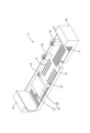
- FIG. 1 is a perspective view of an electrical device according to a first embodiment.
- FIG. 2 is an exploded perspective view of the electrical device of Embodiment 1.
- FIG. 3 is a perspective view of the base member of Embodiment 1.
- FIG. 4 is a perspective view of the cover of Embodiment 1.
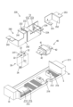
- FIG. 5 is an exploded perspective view of the base member, relay, fuse, and bus bar of Embodiment 1.
- FIG. 6 is a perspective view of the intermediate bus bar of Embodiment 1.
- FIG. 7 is a perspective view of the relay-side bus bar of the first embodiment.
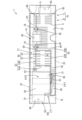
- FIG. 8 is a plan view of the base member, relay, fuse, and bus bar of Embodiment 1.
- FIG. 9 is an exploded perspective view of the electrical device according to the second embodiment.
- FIG. 9 is an exploded perspective view of the electrical device according to the second embodiment.
- FIG. 10 is a perspective view of the intermediate bus bar according to the second embodiment.
- FIG. 11 is an exploded perspective view of the electrical device of Embodiment 3.
- FIG. 12 is an exploded perspective view of the base member, relay, fuse, and bus bar of Embodiment 3.
- FIG. 13 is a perspective view of the intermediate bus bar of Embodiment 3.
- FIG. 14 is a perspective view of the electrical device of Embodiment 4.
- FIG. 15 is an exploded perspective view of the electrical device according to the fourth embodiment with the cover removed.
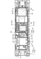
- FIG. 16 is a plan view of the base member, relay, fuse, and bus bar of Embodiment 4.
- FIG. 17 is a plan view of the base member of Embodiment 4.
- FIG. 18 is a bottom view of the cover of Embodiment 4.
- FIG. 16 is a plan view of the base member, relay, fuse, and bus bar of Embodiment 4.
- FIG. 17 is a plan view of the base member of Embodiment 4.
- FIG. 19 is a cross-sectional view taken at a fastening position between the relay and the bus bar according to the fourth embodiment.
- FIG. 20 is a cross-sectional view taken at a fastening position of the fuse and bus bar according to the fourth embodiment.
- FIG. 21 is an exploded perspective view of the base member, relay, fuse, and bus bar of Embodiment 4.
- FIG. 22 is a perspective view of the intermediate bus bar of Embodiment 4.
- An electrical device disclosed in this specification includes a heat generating component that includes a terminal and generates heat when energized, and a bus bar that is connected to the terminal, and the bus bar is connected to the inner laminated layer that is connected to the terminal.
- a busbar piece comprising a spacer section, a spacer section that is continuous with the inner layered section, an outer layered section that is stacked on the inner layered section, and a spaced section that is continuous with the outer layered section and is spaced apart from the one spaced section. and another busbar piece provided with another spacing part arranged at the same time.
- the busbar can be arranged within a limited space while increasing the surface area of the busbar and improving the heat radiation efficiency, and it is possible to achieve both miniaturization of the electrical equipment and improvement of the heat radiation efficiency.
- the area of the inner surface of the one spaced part facing the other spaced part is the area of the inner surface of the one busbar piece facing the other busbar piece. It may be 30% or more of the area of the entire inner surface arranged. According to such a configuration, heat dissipation efficiency can be reliably improved.
- the one separation part and the other separation part may be arranged in a space adjacent to the heat generating component. According to such a configuration, by effectively utilizing the space adjacent to the heat generating component, it is possible to improve the heat generation efficiency while avoiding an increase in the size of the electrical equipment.
- the bus bar may include an erected wall rising from the outer laminated portion or the inner laminated portion. According to such a configuration, in the bus bar, the volume can be increased in the vicinity of the connection portion with the terminal that easily generates heat, and it is possible to suppress the temperature rise, especially during short-term energization in which a large current flows for a short time. Furthermore, since the surface area of the bus bar increases, heat dissipation efficiency improves.
- a plurality of the heat generating components are provided, and the one bus bar piece is connected to the one inner laminated layer connected to the one spaced apart part. and one of the outer laminated parts, the other busbar piece includes another of the inner laminated parts and another of the outer laminated parts connected to the other separated part, and the plurality of heat generating components
- One of the inner laminated parts and the other outer laminated part are stacked in this order on the terminal provided in one of the plurality of heat generating parts, and the terminal provided in another of the plurality of heat generating parts is stacked in this order.
- the other inner laminated portion and one outer laminated portion may be stacked in this order on the terminal.
- the bus bar includes a cylindrical ventilation tube portion configured with the one separation portion and the other separation portion. I don't mind. According to such a configuration, a space through which air can pass can be secured between one spaced part and another spaced part, and heat radiation efficiency can be improved.
- the one spacing section and the other spacing section may be arranged perpendicularly to each other. According to such a configuration, even if the space adjacent to the heat generating component is narrow, it is possible to arrange the separation part, and the electric device can be downsized.
- At least one of the one separation part and the other separation part may be arranged along the outer surface of the heat generating component. According to such a configuration, heat from the heat generating components is efficiently transmitted to the bus bar, and heat dissipation efficiency can be improved.
- the electrical device including a case that houses the heat generating component and the bus bar therein, the case including a case wall having a ventilation hole. I don't mind. According to such a configuration, air can be circulated inside the case, and heat radiation efficiency can be improved.
- the case may include the case wall arranged along the one separation section or the other separation section. According to such a configuration, heat generation efficiency is improved by receiving air flowing in from the ventilation hole at the separation part.
- the electrical device including a case that houses the heat generating component and the bus bar inside, the case having a ventilation hole and arranged perpendicularly to the ventilation tube section. It does not matter if the case has walls that are According to such a configuration, the air flowing in from the ventilation hole can smoothly pass through the inside of the ventilation cylinder part, and the heat radiation efficiency from the ventilation cylinder part is improved.
- the other separating part extends linearly from the outer laminated part, and the one separating part extends from the other separating part.
- one intersection extending in a first direction that intersects with the separation part; and one slope that connects the inner laminated part and the first intersection, the first slope It may be arranged so as to be inclined so as to move away from the other separation part as it approaches the one intersection.
- the first direction is preferably a direction forming an angle of approximately 60° to 120° with respect to the other separating portions, and may be a vertical direction forming an angle of 90° with respect to the other separating portions, for example. .
- the surface area of the first intersection decreases by providing the first slope, but the increase in the surface area of the first slope is greater than the decrease in the surface area of the first intersection. is larger, so the surface area of the busbar increases. Further, by providing one inclined portion, the surface area of the other separating portion increases, so the surface area of the bus bar increases. In this way, in the bus bar, the surface area can be increased in the vicinity of the connection portion with the terminal that tends to generate heat, and the temperature rise can be suppressed, especially during short-term energization where a large current flows for a short time.
- the electrical device including a case that houses the heat generating component and the bus bar inside, the case disposed along the inner surface of the bus bar.
- the bus bar may be integrally provided with an inner case wall arranged along the outer surface of the bus bar and an outer case wall arranged along the outer surface of the bus bar.
- the bus bar extends toward the first lateral region located on the side of the heat generating component.
- one extended part extending from the separating part; and another extended part extending from the other separating part toward a second lateral region located on the opposite side of the first lateral region centering on the heat generating component; It is also possible to further include at least one of the extension parts.
- the surface area of the bus bar is increased by at least one of the expanded portions, so that the heat dissipation efficiency of the bus bar can be improved.
- the first side region and the second side region of the heat generating component are low temperature regions away from the terminals, which are likely to be sources of heat generation, so that the heat dissipation efficiency in at least one of the expanded portions can be improved.
- Embodiment 1 will be described with reference to FIGS. 1 to 8.
- the electrical device 1 of this embodiment is mounted on a vehicle such as an electric vehicle or a hybrid vehicle, and is arranged in a power supply path from a power source such as a battery to a load such as a motor.
- the electrical device 1 includes a relay 30 (an example of a heat-generating component), a fuse 40 (an example of a heat-generating component), an intermediate bus bar 50 (an example of a bus bar), and a relay-side bus bar 70 (an example of a bus bar). (one example of a bus bar), a fuse-side bus bar 90, and a case 10 that accommodates these components inside.
- the case 10 is made of synthetic resin and, as shown in FIG. A cover 21 that covers 70 and 90 is provided.
- the base member 11 includes a rectangular plate-shaped base plate 12 (an example of a case wall), two partition walls 13 rising from two long sides of the base plate 12, and two partition walls 13 on the base plate 12.
- Two connection stands 14 each rising from one short side are provided.
- a relay pedestal 15 for mounting the relay 30 and two mounting columns 18 for mounting the fuse 40 are arranged on one surface of the base plate 12.
- the relay pedestal 15 includes a pedestal main body 16 that supports the relay 30, and two mounting protrusions 17 that protrude from the pedestal main body 16.
- the two mounting columns 18 have a prismatic shape. Nuts (not shown) are respectively installed on the mounting protrusion 17 and the mounting post 18 by a known method such as insert molding or press-fitting.
- the cover 21 has a rectangular plate shape, and includes a top wall 22 (an example of a case wall) facing the base plate 12, and two long sides of the top wall 22.
- two first side walls 23 (an example of a case wall) extending from the top wall 22 and disposed along each of the two partition walls 13; and two second side walls 24 extending from the two short sides of the top wall 22.
- the base plate 12, the ceiling wall 22, and the two first side walls 23 have a plurality of slits S (an example of ventilation holes) for circulating air inside the case 10, as shown in FIGS. 3 and 4. are doing. It is preferable that the slit S is as large as possible without allowing the operator's fingers to enter it.
- the relay 30 is a mechanical relay to which a relatively large current from the vehicle battery is applied, and as shown in FIG. It includes two relay terminals 32 (an example of a terminal) and a partition wall 33 arranged in the relay body 31, and two mounting pieces 34 protruding from the relay body 31.
- the two relay terminals 32 have a nut shape to which a bolt as a fastening member is fastened.
- the partition wall 33 is arranged between the two relay terminals 32, and the creepage distance between the two relay terminals 32 is set by the partition wall 33.
- the fuse 40 includes a fuse body 41 and two fuse terminals 42 (an example of a terminal) protruding from the fuse body 41.
- the fuse terminal 42 is made of metal and has a plate shape.
- the intermediate bus bar 50 is a bus bar that connects the relay 30 and the fuse 40, and as shown in FIGS. 5 and 6, it includes a first bus bar piece 51 (an example of one bus bar piece) and a second bus bar piece 61 ( (an example of another bus bar piece).
- the first bus bar piece 51 is a member obtained by punching and bending a metal plate material, and as shown in FIG. ), a first spaced part 53 (one example of a spaced part) connected to the first inner laminated part 52 , and a first outer laminated part 54 connected to the first spaced part 53 and connected to the fuse terminal 42 (Outer laminated part, an example of one outer laminated part).
- the first inner laminated portion 52 has a flat plate shape.
- the first spacing part 53 includes a flat first vertical plate part 53A extending perpendicularly from the first inner laminated part 52 and a flat first horizontal plate part 53B extending perpendicularly from the first vertical plate part 53A. It is L-shaped.
- the first outer laminated portion 54 has a flat plate shape and extends within the same plane from the first horizontal plate portion 53B.
- the second bus bar piece 61 is a member obtained by punching and bending a metal plate material, and as shown in FIGS. 6 and 8, the second outer laminated portion 62 (outer laminated portion, etc. (an example of an outer laminated part), a second spaced part 63 (an example of another spaced part) connected to the second outer laminated part 62, and a second inner part connected to the second spaced part 63 and connected to the fuse terminal 42. It includes a laminated part 64 (an example of an inner laminated part, another inner laminated part) and an upright wall 65 extending from the second outer laminated part 62.
- the second outer laminated portion 62 has a flat plate shape.
- the second separating portion 63 includes a flat second horizontal plate portion 63A extending in the same plane from the second outer laminated portion 62, and a flat second vertical plate portion extending perpendicularly from the second horizontal plate portion 63A. 63B, forming an L-shape.
- the second inner laminated portion 64 has a flat plate shape and extends perpendicularly from the second vertical plate portion 63B.
- the standing wall 65 is disposed adjacent to the second outer laminated portion 62 and extends perpendicularly from the edge of the second outer laminated portion 62 on the opposite side to the second spacing portion 63 .
- the first inner laminated part 52 and the second outer laminated part 62 are overlapped, the first outer laminated part 54 and the second inner laminated part 64 are overlapped, and the first The spacing section 53 and the second spacing section 63 are spaced apart from each other. It is preferable that the first separation part 53 and the second separation part 63 are separated by a distance that does not transfer heat to each other.
- the first vertical plate part 53A and the second vertical plate part 63B are arranged parallel to each other, the first horizontal plate part 53B and the second horizontal plate part 63A are arranged parallel to each other, and the first spaced part 53 and The second separating portion 63 constitutes a cylindrical ventilation tube portion T1.
- the area of the inner surface of the first separating part 53 facing the second separating part 63 is 30% or more of the area of the entire inner surface of the first busbar piece 51 facing the second busbar piece 61. occupy Similarly, the area of the inner surface of the second spacing portion 63 facing the first spacing portion 53 is 30% of the area of the entire inner surface of the second busbar piece 61 facing the first busbar piece 51. % or more.
- the relay-side bus bar 70 is a bus bar for external connection connected to the relay 30, and as shown in FIGS. 5 and 7, it includes a third bus bar piece 71 (an example of one bus bar piece) and a fourth bus bar piece. 81 (an example of another bus bar piece).
- the third bus bar piece 71 is a member obtained by punching and bending a metal plate, and includes a third inner laminated portion 72 (an example of an inner laminated portion) connected to the relay terminal 32; It includes a third spacing section 73 (an example of one spacing section) continuous to the third inner laminated section 72, and a first external connection section 74 for external connection continuous to the third spacing section 73.
- the third inner laminated portion 72 has a flat plate shape.
- the third spacing section 73 has a flat plate shape and extends perpendicularly from the third inner laminated section 72 .
- the first external connecting portion 74 has a flat plate shape and extends perpendicularly from the third spacing portion 73 .
- the fourth bus bar piece 81 is a member obtained by punching and bending a metal plate material, and is connected to a fourth outer laminated part 82 (an example of an outer laminated part) connected to the relay terminal 32 and a fourth outer laminated part 82. It includes a continuous fourth spacing part 83 (an example of another spacing part) and a second external connection part 84 for external connection continuous to the fourth spacing part 83.
- the fourth outer laminated portion 82 has a flat plate shape.
- the fourth separating portion 83 has a flat plate shape and extends perpendicularly from the fourth outer laminated portion 82 .
- the second external connection portion 84 has a flat plate shape and extends from the fourth separation portion 83 in the same plane.
- the third inner laminated part 72 and the fourth outer laminated part 82 are overlapped, the first external connection part 74 and the second external connection part 84 are overlapped, and the third The spacing portion 73 and the fourth spacing portion 83 are spaced apart from each other.
- the third spacing section 73 and the fourth spacing section 83 are arranged perpendicularly to each other. It is preferable that the third separation part 73 and the fourth separation part 83 are separated by a distance that does not transfer heat to each other.
- the area of the inner surface of the third separation part 73 facing the fourth separation part 83 is 30% or more of the area of the entire inner surface of the third busbar piece 71 facing the fourth busbar piece 81. occupy Similarly, the area of the inner surface of the fourth separating part 83 facing the third separating part 73 is 30% of the area of the entire inner surface of the fourth busbar piece 81 facing the third busbar piece 71. % or more.
- the fuse-side bus bar 90 is a bus bar for external connection that is connected to the fuse 40.
- the fuse-side bus bar 90 is a member formed by punching and bending a metal plate, and as shown in FIG. It includes a third external connection part 93 for external connection, and a flat first connection part 92 that connects the first fuse connection part 91 and the third external connection part 93.
- the relay main body 31 is placed on the relay pedestal 15 with the terminal surface 31F1 perpendicular to the base plate 12.
- the relay 30 is fixed to the base member 11 by screwing the two mounting pieces 34 to the two mounting protrusions 17, respectively.
- the intermediate bus bar 50 is arranged so that the first inner laminated part 52 overlaps with one of the relay terminals 32 arranged on the terminal surface 31F1, and the second outer laminated part 62 overlaps with the first inner laminated part 52,
- the first inner laminated portion 52 and the second outer laminated portion 62 are fixed to the relay terminal 32 by screws.
- the standing wall 65 is arranged adjacent to the partition wall 33.
- the relay-side bus bar 70 is arranged such that the third inner laminated portion 72 overlaps with the other relay terminal 32 arranged on the terminal surface 31F1, and the fourth outer laminated portion 82 overlaps with the third inner laminated portion 72, The third inner laminated portion 72 and the fourth outer laminated portion 82 are fixed to the relay terminal 32 by screws.
- the first outer laminated portion 54 overlaps the side surface of one of the mounting columns 18, and the second inner laminated portion 64 overlaps the first outer laminated portion 54. It has become.
- one of the fuse terminals 42 is stacked on the second inner laminated portion 64, and the first outer laminated portion 54, the second inner laminated portion 64, and the fuse terminal 42 are fixed to one of the mounting columns 18 with screws. Ru.
- first fuse connection part 91 is stacked on the other mounting post 18
- the other fuse terminal 42 is stacked on the first fuse connection part 91
- the first fuse connection part 91 and the fuse terminal 42 are screwed together so that they are connected to each other. It is fixed to the mounting post 18 of.
- the fixing of the relay 30, fuse 40, and bus bars 50, 70, and 90 to the base member 11 is completed.
- the cover 21 is assembled to the base member 11, thereby completing the assembly of the electrical device 1.
- the relay 30 is arranged with the terminal surface 31F1 perpendicular to the base plate 12, and the fuse 40 is arranged with the two fuse terminals 42 perpendicular to the base plate 12. It is arranged in such a position.
- the intermediate bus bar 50 is composed of two bus bar pieces 51 and 61, and includes a first separating part 53 and a second separating part 63 that are spaced apart from each other. According to such a configuration, the intermediate bus bar 50 can be arranged within a limited space while increasing the surface area of the intermediate bus bar 50 and improving heat dissipation efficiency.
- the ventilation tube portion T1 which is composed of the first spacing portion 53 and the second spacing portion 63, is arranged in a relatively wide space between the relay 30 and the fuse 40 in an attitude perpendicular to the base plate 12. ing.
- the first spacing section 53 and the second spacing section 63 are arranged using the space between the relay 30 and the fuse 40, it is possible to improve the heat generation efficiency while avoiding an increase in the size of the electrical device 1.
- the first separating part 53 and the second separating part 63 constitute the cylindrical ventilation pipe part T1 a space for air to pass between the first separating part 53 and the second separating part 63 is ensured. This can improve heat dissipation efficiency.
- air convection can be caused efficiently and heat generation efficiency can be improved.
- the first inner laminated portion 52 and the second outer laminated portion 62 are stacked in this order on the relay terminal 32, and the intermediate bus bar 50 and the fuse terminal 42 are connected to each other.
- the second inner laminated portion 64 and the first outer laminated portion 54 are stacked on the fuse terminal 42 in this order. That is, the overlapping order of the first bus bar piece 51 and the second bus bar piece 61 with respect to the relay terminal 32 and the fuse terminal 42 is reversed on the relay 30 side and the fuse 40 side.
- the second bus bar piece 61 includes an upright wall 65.
- the relay 30 of this embodiment is a mechanical relay, and includes a fixed contact, a movable piece that can come into contact with and separate from the fixed contact, and an excitation coil that switches the connection state between the movable piece and the fixed contact.
- heat is likely to be generated near an internal fixed contact, and this fixed contact is connected to a relay terminal 32. Therefore, in the second bus bar piece 61, by arranging the standing wall 65 adjacent to the second outer laminated portion 62 connected to the relay terminal 32, the intermediate bus bar 50 can be connected to the relay terminal 32 that easily generates heat.
- the volume can be increased in the vicinity of the part, and the temperature rise can be suppressed especially during short-term energization where a large current flows for a short time. Furthermore, since the surface area of intermediate bus bar 50 increases, heat from relay 30 can be efficiently dissipated.
- the relay-side bus bar 70 is also composed of two bus bar pieces 71 and 81, and includes a third separating part 73 and a fourth separating part 83 that are spaced apart from each other. According to such a configuration, the relay-side bus bar 70 can be arranged within a limited space while increasing the surface area of the relay-side bus bar 70 and improving heat dissipation efficiency.
- the third spacing section 73 and the fourth spacing section 83 are arranged perpendicularly to each other, and are arranged in the space between the relay 30 and the case 10. According to such a configuration, even if the space adjacent to the relay 30 is relatively narrow, the third spacing section 73 and the fourth spacing section 83 can be arranged. Further, the fourth separating portion 83 is arranged along an outer surface 31F2 of the relay 30 that is different from the terminal surface 31F1. Thereby, the heat from the relay 30 is easily transmitted to the relay-side bus bar 70, and the heat can be efficiently radiated.
- the base plate 12, the top wall 22, and the two first side walls 23 each have a plurality of slits S.
- air can be circulated inside the case 10, and the efficiency of heat radiation from the bus bars 50, 70, and 90 can be improved.
- the first horizontal plate part 53B and the second horizontal plate part 63A are arranged along each of the two first side walls 23, the air flowing in from the slit S of the first side wall 23 is The heat is received by the plate portion 53B and the second horizontal plate portion 63A, and the efficiency of heat radiation from the intermediate bus bar 50 is improved.
- the third spacing section 73 since the third spacing section 73 is arranged along the ceiling wall 22, the third spacing section 73 receives the air flowing in from the slit S of the ceiling wall 22, which improves the heat dissipation efficiency from the relay side bus bar 70. will improve. Furthermore, the base plate 12 and the ceiling wall 22 arranged perpendicularly to the vent portion T1 have slits S. Thereby, the air flowing in from the slit S can smoothly pass through the inside of the ventilation tube portion T1, and the efficiency of heat radiation from the ventilation tube portion T1 is improved.
- the electrical device 1 includes the relay 30 that includes the relay terminal 32 and generates heat when energized, and the intermediate bus bar 50 and the relay-side bus bar 70 that are connected to the relay terminal 32.
- the intermediate bus bar 50 includes a first bus bar piece 51 including a first inner laminated portion 52 connected to the relay terminal 32 and a first separation portion 53 continuous to the first inner laminated portion 52;
- the second bus bar piece 61 includes a first outer laminated portion 54 that is laminated, and a second spacing portion 63 that is continuous with the first outer laminated portion 54 and is spaced apart from the first spacing portion 53.
- the relay-side bus bar 70 includes a third bus bar piece 71 including a third inner laminated part 72 connected to the relay terminal 32 and a third separation part 73 continuous to the third inner laminated part 72, and a third inner laminated part 72.
- a fourth bus bar piece 81 includes a fourth outer laminated portion 82 stacked on the fourth outer laminated portion 82 and a fourth spacing portion 83 connected to the fourth outer laminated portion 82 and spaced apart from the third spacing portion 73. ing.
- the busbars 50 and 70 can be arranged in a limited space while increasing the surface area of the busbars 50 and 70 to improve heat dissipation efficiency, thereby reducing the size of the electrical equipment 1 and improving the heat dissipation efficiency. It is possible to achieve both improvements.
- the area of the inner surface of the first separating part 53 of the intermediate bus bar 50 facing the second separating part 63 is the area of the entire inner surface of the first bus bar piece 51 facing the second bus bar piece 61. It occupies more than 30% of the area.
- the area of the inner surface of the second spacing portion 63 facing the first spacing portion 53 is 30% of the area of the entire inner surface of the second busbar piece 61 facing the first busbar piece 51. % or more.
- the area of the inner surface of the third separating part 73 facing the fourth separating part 83 is 30% of the area of the entire inner surface of the third bus bar piece 71 facing the fourth bus bar piece 81.
- the area of the inner surface of the fourth separating part 83 facing the third separating part 73 is 30% of the area of the entire inner surface of the fourth busbar piece 81 facing the third busbar piece 71. % or more. According to such a configuration, heat dissipation efficiency can be reliably improved.
- first spacing section 53 and a second spacing section 63 are arranged in a space adjacent to the relay 30 and the fuse 40. Further, a third spacing section 73 and a fourth spacing section 83 are arranged in a space adjacent to the relay 30. According to such a configuration, by effectively utilizing the space adjacent to the relay 30 and the fuse 40, it is possible to improve the heat generation efficiency while avoiding an increase in the size of the electrical device 1.
- the intermediate bus bar 50 includes an upstanding wall 65 rising from the second outer laminated portion 62. According to such a configuration, the volume of the intermediate bus bar 50 can be increased in the vicinity of the connection part with the relay terminal 32 which is particularly prone to heat generation, and the temperature rise can be suppressed especially during short-term energization where a large current flows for a short time. be able to. Furthermore, since the surface area of the intermediate bus bar 50 increases, heat radiation efficiency improves.
- the electrical device 1 is provided with a relay 30 and a fuse 40
- the first busbar piece 51 is provided with a first inner laminated portion 52 and a first outer laminated portion 54 that are connected to the first spacing portion 53
- the two busbar pieces 61 include a second inner laminated portion 64 and a second outer laminated portion 62 that are connected to the second separation portion 63, and are connected to the first inner laminated portion 52 and the second outer laminated portion 62 with respect to the relay terminal 32 provided in the relay 30.
- the second outer laminated portion 62 is stacked in this order, and the second inner laminated portion 64 and the first outer laminated portion 54 are stacked in this order on the fuse terminal 42 provided in the fuse 40 .
- the third spacing section 73 and the fourth spacing section 83 are arranged perpendicularly to each other. According to such a configuration, even if the space adjacent to the relay 30 is narrow, the separation parts 73 and 83 can be arranged, and the electric device 1 can be downsized.
- a fourth spacing section 83 is arranged along the outer surface 31F2 of the relay 30. According to such a configuration, heat from the relay 30 is efficiently transmitted to the relay-side bus bar 70, and heat dissipation efficiency can be improved.
- the electrical device 1 includes a case 10 that houses a relay 30, a fuse 40, and bus bars 50, 70, and the case 10 includes a base plate 12 having a slit S, a top wall 22, and two first side walls. 23. According to such a configuration, air can be circulated inside the case 10, and heat radiation efficiency can be improved.
- the two first side walls 23 are arranged along the first horizontal plate part 53B of the first separating part 53 and the second horizontal plate part 63A of the second separating part 63, and the top wall 22 is arranged along the first horizontal plate part 53B of the first separating part 53 and the second horizontal plate part 63A of the second separating part 63. 4 along the spaced apart portion 83.
- the first horizontal plate portion 53B, the second horizontal plate portion 63A, and the fourth separation portion 83 receive the air flowing in from the slit S, thereby improving heat generation efficiency.
- the intermediate bus bar 50 includes a cylindrical vent portion T1 that is configured of a first separating portion 53 and a second separating portion 63. According to such a configuration, a space through which air can pass can be secured between the first separating part 53 and the second separating part 63, and heat radiation efficiency can be improved.
- the base plate 12 and the top wall 22 are arranged perpendicularly to the vent portion T1. According to such a configuration, the air flowing in from the slit S can smoothly pass through the inside of the ventilation tube portion T1, and the efficiency of heat radiation from the ventilation tube portion T1 is improved.
- Embodiment 2 will be described with reference to FIGS. 9 and 10.
- the electrical device 100 of the second embodiment differs from the first embodiment in the configuration of the intermediate bus bar 110.
- the same components as in Embodiment 1 are denoted by the same reference numerals, and the description thereof will be omitted.
- the intermediate busbar 110 includes a first busbar piece 51 (an example of one busbar piece), a fifth busbar piece 111 (an example of another busbar piece), and a sixth busbar piece 121.
- the first busbar piece 51 has the same configuration as the first embodiment
- the fifth busbar piece 111 has the same configuration as the second busbar piece 61 of the first embodiment except that it does not have the standing wall 65. It is equipped with
- the sixth busbar piece 121 (an example of another busbar piece) includes a fifth separating part 122 (an example of another separating part) having a flat plate shape, and two flat plate-shaped separating parts 122 extending diagonally from both ends of the fifth separating part 122, respectively.
- two intermediate laminated parts 123 and 124 (an example of an outer laminated part).
- the first inner laminated portion 52, one intermediate laminated portion 123, and the second outer laminated portion 62 are connected to the terminal surface 31F1. They are stacked in this order with respect to the arranged relay terminals 32. Further, at the connection portion between the intermediate bus bar 110 and the fuse terminal 42, the second inner laminated portion 64, the other intermediate laminated portion 124, and the first outer laminated portion 54 are stacked on the fuse terminal 42 in this order. It is being The first spacing section 53, the second spacing section 63, and the fifth spacing section 122 are spaced apart from each other. The first spacing section 53 and the second spacing section 63 constitute a cylindrical ventilation tube section T1, and the fifth spacing section 122 is arranged diagonally between the first spacing section 53 and the second spacing section 63. It is located.
- the same effects as in the first embodiment can be achieved. Furthermore, the presence of the fifth spacing portion 122 allows the surface area of the intermediate bus bar 110 to be further increased, thereby further improving the heat dissipation efficiency.
- the electrical device 200 of the third embodiment includes a relay 30, a fuse 40, an intermediate bus bar 220 (an example of a bus bar), a relay side bus bar 240 (an example of a bus bar), and a fuse side bus bar 250. , and a case 210 that houses these parts inside.
- the case 210 is made of synthetic resin and includes a base member 211 and a cover 217.
- the base member 211 includes a base plate 212 (an example of a case wall), two partition walls 13, and two connection stands 14.
- the base plate 212 has a rectangular plate shape and has a plurality of slits S, as in the first embodiment.
- a pedestal 213 for mounting the relay 30 and two mounting ribs 216 for mounting the fuse 40 are arranged on one surface of the base plate 212.
- the pedestal 213 includes a pedestal main body 214 that supports the relay 30 and two mounting protrusions 215 that protrude from the pedestal main body 214.
- the two mounting ribs 216 have a rectangular parallelepiped shape. Nuts (not shown) are respectively disposed on the mounting protrusion 215 and the mounting rib 216 by a known method such as insert molding or press-fitting.
- the configuration of the cover 217 is the same as that of Embodiment 1 except for the detailed shape of the top wall 218, etc., so the same components as Embodiment 1 are given the same reference numerals and explanations will be omitted.
- the relay 30 and the fuse 40 have the same configuration as in the first embodiment, but are attached in a different direction to the base plate 212. Specifically, as shown in FIG. 11, the relay 30 is arranged so that the terminal surface 31F1 is parallel to the base plate 212, and the fuse 40 is arranged so that the fuse terminal 42 is parallel to the base plate 212. It is arranged in the same direction. Along with this, the shapes of bus bars 220, 240, and 250 are also different from those in the first embodiment.
- the intermediate busbar 220 includes a seventh busbar piece 221 (an example of one busbar piece) and an eighth busbar piece 231 (an example of another busbar piece).
- the seventh bus bar piece 221 is a member obtained by punching and bending a metal plate, and is a member obtained by punching and bending a metal plate.
- a laminated portion (an example of an inner laminated portion), a seventh spaced portion 223 (an example of a first spaced portion) connected to the seventh inner laminated portion 222, and a seventh spaced portion 223 (an example of a first spaced portion) connected to the seventh spaced portion 223 and connected to the fuse terminal 42.
- a seventh outer laminated portion 224 (an example of one outer laminated portion) is provided.
- the seventh inner laminated portion 222 includes a seventh inner connecting piece 222A having a flat plate shape and a seventh inner extension portion 222B extending perpendicularly from the seventh inner connecting piece 222A.
- the seventh separation part 223 includes a flat seventh vertical plate part 223A extending perpendicularly from the seventh inner extension part 222B, and a flat seventh horizontal plate part 223B extending perpendicularly from the seventh vertical plate part 223A. It is L-shaped.
- the seventh outer laminated portion 224 has a flat plate shape, and includes a seventh outer extension portion 224A extending from the seventh horizontal plate portion 223B in a direction opposite to the seventh vertical plate portion 223A, and a seventh outer extension portion 224A extending perpendicularly from the seventh outer extension portion 224A. 7 outer connection piece 224B.
- the eighth bus bar piece 231 includes an eighth outer laminated portion 232 (an example of an outer laminated portion, another outer laminated portion) connected to the relay terminal 32, and an eighth spaced apart portion 233 (an example of another outer laminated portion) connected to the eighth outer laminated portion 232. (an example of a spaced apart part), and an eighth inner laminated part 234 (an example of an inner laminated part, another inner laminated part) that is continuous with the eighth spaced part 233 and connected to the fuse terminal 42.
- the eighth outer laminated portion 232 includes an eighth outer connecting piece 232A having a flat plate shape and an eighth outer extending portion 232B extending perpendicularly from the eighth outer connecting piece 232A.
- the eighth separation part 233 includes a flat eighth horizontal plate part 233A extending in the same plane from the eighth outer extension part 232B, and a flat eighth vertical plate part extending perpendicularly from the eighth horizontal plate part 233A. 233B, forming an L-shape.
- the eighth inner laminated portion 234 has a flat plate shape, and includes an eighth inner extension portion 234A that extends vertically from the eighth vertical plate portion 233B in a direction opposite to the eighth horizontal plate portion 233A, and an eighth inner extension portion 234A that extends vertically from the eighth inner extension portion 234A. and an extending eighth inner connecting piece 234B.
- the seventh inner laminated part 222 and the eighth outer laminated part 232 are overlapped, the seventh outer laminated part 224 and the eighth inner laminated part 234 are overlapped, and the seventh spaced part 223 and the eighth spacing portion 233 are spaced apart from each other.
- the seventh separating portion 223 and the eighth separating portion 233 constitute a cylindrical vent portion T2.
- the seventh inner connecting piece 222A of the seventh inner laminated part 222 and the eighth outer connecting piece 232A of the eighth outer laminated part 232 are connected to each other. are stacked in this order on the relay terminals 32 arranged on the terminal surface 31F1.
- the eighth inner connecting piece 234B of the eighth inner laminated part 234 and the seventh outer connecting piece 224B of the seventh outer laminated part 224 are connected to the fuse terminal 42. They are stacked in the order of levers.
- the relay-side bus bar 240 is a member formed by punching and bending a metal plate material, and as shown in FIG. and an L-shaped plate-shaped second connecting portion 242 that connects the relay connecting portion 241 and the fourth external connecting portion 243.
- the fuse-side bus bar 250 is a member formed by punching and bending a metal plate, and as shown in FIG. It includes a fifth external connection part 253 for connection, and an L-shaped plate-shaped third connection part 252 that connects the second fuse connection part 251 and the fifth external connection part 253.
- This embodiment also provides the same effects as the first embodiment.
- the electrical device 300 of the fourth embodiment includes a relay 330 (an example of a heat-generating component), a fuse 340 (an example of a heat-generating component), and an intermediate bus bar 350 (an example of a heat-generating component).
- a relay 330 an example of a heat-generating component
- a fuse 340 an example of a heat-generating component
- an intermediate bus bar 350 an example of a heat-generating component.
- a relay-side bus bar 370 an example of a bus bar
- a fuse-side bus bar 390 a case 310 that accommodates these components inside.
- the case 310 is made of synthetic resin, and, as shown in FIG. 15, includes a base member 311 to which the relay 330 and the fuse 340 are fixed, and a base member 311 that is assembled to the base member 311 and includes the relay 330, the fuse 340, and the bus bars 350, 370. , 390.
- the base member 311 includes a rectangular plate-shaped base plate 312, two partition walls 313 rising from two long sides of the base plate 312, and two partition walls 313 rising from two short sides of the base plate 312. and two mounting seats 314.
- a relay mounting portion 315 for mounting the relay 330 and a fuse mounting portion 316 for mounting the fuse 340 are arranged on one surface of the base plate 312.
- the cover 321 has a rectangular plate shape, extends from a top wall 322 facing the base plate 312, and two long sides of the top wall 322, and extends from two long sides of the two partition walls 313.
- Two first side walls 323 arranged along each side, two second side walls 324 extending from the two short sides of the top wall 322, and a bus bar housing wall that houses the relay side bus bar 370 and the intermediate bus bar 350 therein. 325.
- busbar housing wall 318 similar to the busbar housing wall 325 is provided on the base member 311, but the busbar housing wall 325 on the cover 321 side is larger than the busbar housing wall 318 on the base member 311 side. It is formed longer in the vertical direction.
- a plurality of ventilation holes H for circulating air inside the case 310 are formed in a part of the top wall 322.
- the ventilation hole H is preferably large enough that the operator's fingers cannot fit into it.
- the relay 330 is a mechanical relay to which a relatively large current from the vehicle battery is applied, and as shown in FIG.
- the device includes two relay terminals 332 (an example of a terminal) arranged in a partition wall 333 and two relay terminals 332 (an example of a terminal).
- the two relay terminals 332 have a nut shape to which a bolt as a fastening member is fastened.
- the partition wall 333 is arranged between the two relay terminals 332, and the creepage distance between the two relay terminals 332 is set by the partition wall 333.
- the fuse 340 includes a fuse body 341 and two fuse terminals 342 (an example of a terminal) protruding from the fuse body 341.
- the fuse terminal 342 is made of metal and has a plate shape.
- the intermediate bus bar 350 is a bus bar that connects the relay 330 and the fuse 340, and as shown in FIGS. 21 and 22, it includes a first bus bar piece 351 (an example of one bus bar piece) and a second bus bar piece 361 (an example of one bus bar piece). (an example of another bus bar piece).
- the first bus bar piece 351 is a member obtained by punching and bending a metal plate material, and as shown in FIGS. 19 and 22, the first inner laminated portion 352 (an example of an inner laminated portion ), a first separation part 353 (one example of a separation part) connected to the first inner lamination part 352 , and a first inner lamination part 354 (an example of an inner lamination part) connected to the first separation part 353 and connected to the fuse terminal 342 (an example of a section), and a first extension section 355 (an example of an extension section) that is continuous with the first separation section 353 and extends to a first lateral region R1 located on the side of the fuse 340.
- the second bus bar piece 361 is a member obtained by punching and bending a metal plate material, and is connected to a second outer laminated portion 362 (an example of an outer laminated portion) connected to the relay terminal 332 and a second outer laminated portion 362 that is connected to the relay terminal 332.
- a second spacing portion 363 (an example of another spacing portion) that is continuous
- a second outer laminated portion 364 (an example of an outer laminated portion) that is continuous to the second spacing portion 363 and connected to the fuse terminal 342, and a second spacing portion 363 and extends to a second lateral region R2 located on the opposite side of the first lateral region R1 with the fuse 340 at the center.
- the second spacing portion 363 extends linearly from the second outer laminated portion 362 .
- the first inner laminated portion 352 has a flat plate shape.
- the first separating part 353 includes a first vertical part (an example of one intersection part) 353A disposed perpendicularly to the second separating part 363, a first inner laminated part 352, and a first vertical part 353A arranged perpendicularly to the second separating part 363.
- the first inclined part 353B connects the first vertical part 353A, and the first parallel part 353C continues to the first vertical part 353A and is arranged parallel to the second spaced part 363.
- the first inclined portion 353B is arranged so as to be inclined away from the second spacing portion 363 as it approaches the first vertical portion 353A, and extends linearly.
- the direction in which the first vertical portion 353A extends with respect to the second separation portion 363 is an example of the first direction.
- the first parallel portion 353C and the first extended portion 355 have a flat plate shape.
- the first expanded portion 355 extends in the same plane from the first parallel portion 353C.
- the second outer laminated portion 362, the second separation portion 363, and the second expanded portion 365 have a flat plate shape.
- the second spacing portion 363 extends in the same plane from the second outer laminated portion 362 .
- the second expanded portion 365 extends within the same plane from the second spaced apart portion 363 .
- the first inner laminated portion 354 has a flat plate shape. As shown in FIG. 20, the first inner laminated portion 354 extends horizontally from the lower edge of the first parallel portion 353C toward the second spaced apart portion 363.
- the second outer laminated portion 364 has a flat plate shape. The second outer laminated portion 364 extends horizontally from the lower edge of the second spacing portion 363 toward the first parallel portion 353C.
- the first inner laminated portion 354 is laminated to the fuse terminal 342 of the fuse 340, and the second outer laminated portion 364 is laminated to the first inner laminated portion 354.
- the second outer laminated portion 364, the first inner laminated portion 354, and the fuse terminal 342 are fixed to each other by screws.
- the area of the inner surface of the first separating part 353 facing the second separating part 363 is 30% or more of the area of the entire inner surface of the first bus bar piece 351 facing the second bus bar piece 361. show.
- the area of the inner surface of the second spacing portion 363 facing the first spacing portion 353 is 30% of the area of the entire inner surface of the second busbar piece 361 facing the first busbar piece 351. % or more.
- the relay-side bus bar 370 is a bus bar for external connection connected to the relay 330, and is a member formed by punching and bending a metal plate.
- the relay-side bus bar 370 includes a relay terminal connection section 371 connected to the relay terminal 332, and an external connection section 372 for external connection.
- the relay terminal connection portion 371 has a flat plate shape.
- the external connection part 372 has a flat plate-like vertical part 372A extending vertically from the side edge of the relay terminal connecting part 371, and a flat horizontal part 372B extending horizontally from the lower edge of the vertical part 372A. It is equipped with
- the fuse-side bus bar 390 is a bus bar for external connection that is connected to the fuse 340.
- the fuse-side bus bar 390 has a flat plate shape, is a member formed by punching and bending a metal plate, and is connected to the fuse terminal 342.
- busbar housing wall 325 As shown in FIGS. 15 and 18, the busbar housing wall 325 includes a first busbar housing wall 326 that houses the intermediate busbar 350, and a second busbar housing wall 327 that houses the relay side busbar 370. Since both the first busbar housing wall 326 and the second busbar housing wall 327 have the same configuration, the first busbar housing wall 326 will be described below as an example. Furthermore, the busbar housing wall 318 on the base member 311 side is formed by forming the busbar housing wall 325 on the cover 321 side shorter in the vertical direction, and has the same basic configuration as the busbar housing wall 325, so the following description will be made below. The busbar housing wall 325 on the cover 321 side will be described as a representative.
- the busbar housing wall 325 (first busbar housing wall 326) is formed in a groove shape to match the outer shape of the intermediate busbar 350.
- the bus bar housing wall 325 includes an inner case wall 325A disposed along the inner surface of the first parallel portion 353C of the first spacing portion 353, and an inner case wall 325A disposed along the inner surface of the first parallel portion 353C of the first spacing portion 353. It includes an outer case wall 325B arranged along the outer surface, and a connecting wall 325C arranged along the upper end of the first parallel part 353C of the first separation part 353.
- the upper end of the inner case wall 326A and the upper end of the outer case wall 326B are connected to each other by a connecting wall 326C. Thereby, the inner case wall 326A and the outer case wall 326B are integrally formed.
- the lower end of the inner case wall 326A is connected to the ceiling wall 322.
- the lower end of the outer case wall 326B is connected to the upper end of the first side wall 323.
- the partition wall 313 of the base member 311 is arranged along the outer surface of the first parallel portion 353C of the first spacing portion 353.
- the partition wall 313 is accommodated between the first parallel portion 353C of the first spacing portion 353 and the first side wall 323.
- the ceiling wall 322 is arranged along the upper surface of the second outer laminated portion 364 of the second spacing portion 363 .
- a plurality of cover-side ribs 328 are formed on the outer surface of the outer case wall 325B. Furthermore, a plurality of base-side ribs 317 are formed on the outer surface of the partition wall 313. These ribs 328 and 317 are ribs for reinforcing the busbar housing wall 325 and the partition wall 313, but also function as cooling fins that contribute to improving heat radiation efficiency.
- the first busbar housing wall 326 and the ceiling wall 322 are arranged close to the intermediate busbar 350, so that heat is transferred from the intermediate busbar 350 to the first busbar housing wall 326 and the ceiling wall 322. It's getting easier.
- the second busbar housing wall 327 is disposed close to the relay busbar 370, heat is easily transferred from the relay busbar 370 to the second busbar housing wall 327. Therefore, the heat radiation efficiency can be improved more than when heat is radiated into the air from the intermediate bus bar 350 and the relay-side bus bar 370.
- the relay body 331 is placed on the relay mounting part 315 with the terminal surface 331F1 perpendicular to the base plate 312, and is screwed to the base plate 312, so that the relay 330 is attached to the base member 311. Fixed.
- the first inner laminated part 352 of the intermediate bus bar 350 is arranged so as to overlap one relay terminal 332 arranged on the terminal surface 331F1
- the second outer laminated part 362 is arranged so as to overlap the first inner laminated part 352
- the first inner laminated portion 352 and the second outer laminated portion 362 are fixed to one relay terminal 332 by screws.
- relay terminal connecting portion 371 of the relay side bus bar 370 is arranged so as to overlap the other relay terminal 332 arranged on the terminal surface 331F1, and the relay terminal connecting portion 371 is screwed to the other relay terminal 332. Fixed.
- the intermediate bus bar 350 When the intermediate bus bar 350 is fixed to the relay 330, the first inner laminated portion 354 of the intermediate bus bar 350 overlaps one of the fuse terminals 342, and the second outer laminated portion 364 overlaps the first inner laminated portion 354.
- the situation is as follows. In this state, the second outer laminated portion 364, the first inner laminated portion 354, and one fuse terminal 342 are fixed with screws.
- the fuse-side bus bar 390 is arranged so as to overlap the other fuse terminal 342, and the fuse-side bus bar 390 is fixed to the other fuse terminal 342 by screwing.
- an additional component C such as a relay may be arranged in a space surrounded by the first vertical portion 353A, the first parallel portion 353C, the fuse body 341, and the second spacing portion 363.
- the fixing of the relay 330, fuse 340, and bus bars 350, 370, and 390 to the base member 311 is completed.
- the cover 321 is assembled to the base member 311, thereby completing the assembly of the electrical device 300.
- the relay 330 is arranged with the terminal surface 331F1 perpendicular to the base plate 312, and the fuse 340 is arranged with the two fuse terminals 342 parallel to the base plate 312. It is arranged in such a position.
- relay 330 and fuse 340 When electrical equipment 300 configured as described above is energized, relay 330 and fuse 340 generate heat. Heat from relay 330 and fuse 340 is radiated to busbar housing wall 325 via busbars 350, 370, and 390, and is radiated from busbar housing wall 325 into the air.
- the intermediate bus bar 350 is composed of two bus bar pieces 351 and 361, and includes a first separating part 353 and a second separating part 363 that are spaced apart from each other. According to such a configuration, the intermediate bus bar 350 can be arranged within a limited space while increasing the surface area of the intermediate bus bar 350 and improving heat dissipation efficiency.
- the first vertical section 353A is formed to be short to the extent that it does not reach the second spacing section 363.
- a first inclined part 353B is formed that extends obliquely so as to connect the first vertical part 353A and the first inner laminated part 352.
- the surface area of the first separation part 353 can be increased.
- the second spacing section 363 increases due to the provision of the first inclined section 353B, the surface area of the second spacing section 363 can also be increased.
- the second spacing section 363 extends linearly from the second outer laminated section 362, and the first spacing section 353 includes a first vertical section 353A disposed perpendicularly to the second spacing section 363, and a first
- the first inclined part 353B connects the inner laminated part 352 and the first vertical part 353A, and the first inclined part 353B slopes away from the second separating part 363 as it approaches the first vertical part 353A. It is arranged as follows.
- the surface area of the first vertical portion 353A is reduced by providing the first sloped portion 353B, but the surface area of the first sloped portion 353B is reduced by the decrease in the surface area of the first vertical portion 353A. Since the increase in surface area is larger, the surface area of intermediate bus bar 350 increases. Further, by providing the first inclined portion 353B, the surface area of the second separation portion 363 increases, so the surface area of the intermediate bus bar 350 increases. In this way, the surface area of the intermediate bus bar 350 can be increased near the connection portion with the relay terminal 332, which tends to generate heat, and the temperature rise can be suppressed, especially during short-term energization where a large current flows for a short time.
- the case 310 includes a case 310 that houses a relay 330, a fuse 340, an intermediate bus bar 350, a relay side bus bar 370, and a fuse side bus bar 390.
- the bus bar is integrally provided with an inner case wall 325A arranged thereon and an outer case wall 325B arranged along the outer surface of the bus bar. According to such a configuration, heat is easily transmitted from the inner surface of the bus bar to the inner case wall 325A, and heat is easily transmitted from the outer surface of the bus bar to the outer case wall 325B, so that the heat dissipation efficiency of the bus bar is higher than that of heat dissipation into the air. can be improved.
- the electrical device 300 is equipped with a plurality of heat generating components (a relay 330 and a fuse 340), and the relay 330 is located near the first sloped portion 353B and connected to the first inner laminated portion 352 connected to the first sloped portion 353B. It is located near.
- the first busbar piece 351 further includes a first extension part 355 extending from the first parallel part 353C toward the first side region R1 located on the side of the fuse 340, for example, in the same plane
- the second busbar piece 361 further includes a second extension portion 365 extending from the second spacing portion 363 toward a second side region R2 located on the opposite side to the first side region R1 with the fuse 340 as the center, for example, within the same plane.
- the fuse 340 is located further away from the first inner laminated portion 352 than the relay 330.
- the surface area of the intermediate bus bar 350 is increased by the first extension part 355 and the second extension part 365, so that the heat dissipation efficiency of the intermediate bus bar 350 can be improved.
- the vicinity of the fuse body 341 is less likely to reach a high temperature than the vicinity of the fuse terminal 342.
- the first lateral region R1 and the second lateral region R2 of the fuse 340 are regions on both sides of the fuse body 341, and are low-temperature regions away from the fuse terminal 342, which is likely to be a source of heat generation. The heat dissipation efficiency in the portion 355 and the second extension portion 365 can be improved.
- the standing wall 65 extends from the first outer laminated portion 54, but the standing wall may extend from the inner laminated portion. Moreover, the standing wall may extend from both the outer laminated part and the inner laminated part.
- the base plate 12, the top wall 22, and the two first side walls 23 of the case 10 each had a plurality of slits S. As long as the pores H are arranged in at least one location in the case, a certain effect can be achieved. Further, the case does not need to be provided with ventilation holes.
- Relays and fuses can be installed in any direction with respect to the base member; for example, a relay can be installed with its terminal surface perpendicular to the base member, and a fuse can be installed with its fuse terminals parallel to the base member. It does not matter if they are arranged in the following direction.
- the relay may be arranged with the terminal surface parallel to the base member, and the fuse may be arranged with the fuse terminal perpendicular to the base member.
- the ventilation holes were slits, but the shape of the ventilation holes may be arbitrary.
- the holes may have circular, oval, or polygonal edge shapes. do not have.
- bus bars 50, 70, 90, 110, 220, 240, 250, 350, 370, 390 are screwed to the relay terminals 32, 332 and the fuse terminals 42, 342,
- the bus bar may be connected to the terminal of the heat generating component in any manner, for example, the bus bar may be connected by welding.
- mechanical relays 30, 330 and fuses 40, 340 are illustrated as heat generating components, but the types of heat generating components are not limited to those in the above embodiment, and include, for example, semiconductor switching elements, capacitors, and diodes. etc. is fine.
- the fourth spacing section 83 is disposed along the outer surface 31F2 of the relay 30, but both of the two spacing sections may be disposed along the heat generating component.
- the first inclined portion 353B extends linearly, but the first inclined portion may extend in an arc.
- busbar housing walls 318 and 325 are provided on both the base member 311 and the cover 321, but the busbar housing wall may be provided on only one of the base member 311 and the cover 321.
- the first extended portion 355 extends toward the first lateral region R1 of the fuse 340, but the first extended portion is a connecting portion between the first vertical portion 353A and the first parallel portion 353C. It may extend from the side toward the side area of the relay 330.
- the intermediate bus bar 350 is provided with both the first extension part 355 and the second extension part 365.
- the intermediate bus bar 350 may be provided with only the first extension part 355.
- An intermediate bus bar may be provided with only the extension portion 365.
- the extended portions 355 and 365 are arranged in the side regions R1 and R2, but the extended portions are arranged in a portion where the bus bar is not energized and is close to a heat generation source such as a terminal.
- the extension portion may be arranged in the upper region or the lower region of the fuse body 341.
- the extension parts 355 and 356 extend in the same plane from the separation parts 353 and 363, but they do not necessarily have to extend in the same plane and intersect with the separation parts 353 and 363.
- the extension may be provided so as to extend in an arrangement that
- Embodiments 1 to 3 cases 10 and 210 that are not equipped with the busbar housing wall 325 of Embodiment 4 are illustrated, but cases that are equipped with a busbar housing wall may also be used in Embodiments 1 to 3. .
- Embodiments 1 to 3 the intermediate bus bars 50, 110, 220 without the extension parts 355, 365 of Embodiment 4 are illustrated, but in Embodiments 1 to 3, intermediate bus bars with extension parts are also used. May be used.
Landscapes
- Engineering & Computer Science (AREA)
- Microelectronics & Electronic Packaging (AREA)
- Mechanical Engineering (AREA)
- Connection Or Junction Boxes (AREA)
Priority Applications (3)
| Application Number | Priority Date | Filing Date | Title |
|---|---|---|---|
| JP2024508288A JP7639986B2 (ja) | 2022-03-18 | 2023-03-17 | 電気機器 |
| CN202380025149.2A CN118786761A (zh) | 2022-03-18 | 2023-03-17 | 电气设备 |
| US18/845,290 US20250246890A1 (en) | 2022-03-18 | 2023-03-17 | Electrical device |
Applications Claiming Priority (2)
| Application Number | Priority Date | Filing Date | Title |
|---|---|---|---|
| JP2022043722 | 2022-03-18 | ||
| JP2022-043722 | 2022-03-18 |
Publications (1)
| Publication Number | Publication Date |
|---|---|
| WO2023176980A1 true WO2023176980A1 (ja) | 2023-09-21 |
Family
ID=88023454
Family Applications (1)
| Application Number | Title | Priority Date | Filing Date |
|---|---|---|---|
| PCT/JP2023/010765 Ceased WO2023176980A1 (ja) | 2022-03-18 | 2023-03-17 | 電気機器 |
Country Status (4)
| Country | Link |
|---|---|
| US (1) | US20250246890A1 (https=) |
| JP (1) | JP7639986B2 (https=) |
| CN (1) | CN118786761A (https=) |
| WO (1) | WO2023176980A1 (https=) |
Cited By (3)
| Publication number | Priority date | Publication date | Assignee | Title |
|---|---|---|---|---|
| WO2025063155A1 (ja) * | 2023-09-22 | 2025-03-27 | 株式会社オートネットワーク技術研究所 | 一対の回路ユニット |
| WO2025063153A1 (ja) * | 2023-09-22 | 2025-03-27 | 株式会社オートネットワーク技術研究所 | 回路ユニット |
| WO2025063154A1 (ja) * | 2023-09-22 | 2025-03-27 | 株式会社オートネットワーク技術研究所 | 回路ユニット |
Citations (2)
| Publication number | Priority date | Publication date | Assignee | Title |
|---|---|---|---|---|
| JP2020194872A (ja) * | 2019-05-28 | 2020-12-03 | 株式会社オートネットワーク技術研究所 | 回路構成体 |
| JP2021121157A (ja) * | 2020-01-30 | 2021-08-19 | 株式会社オートネットワーク技術研究所 | 回路構成体 |
-
2023
- 2023-03-17 CN CN202380025149.2A patent/CN118786761A/zh active Pending
- 2023-03-17 JP JP2024508288A patent/JP7639986B2/ja active Active
- 2023-03-17 US US18/845,290 patent/US20250246890A1/en active Pending
- 2023-03-17 WO PCT/JP2023/010765 patent/WO2023176980A1/ja not_active Ceased
Patent Citations (2)
| Publication number | Priority date | Publication date | Assignee | Title |
|---|---|---|---|---|
| JP2020194872A (ja) * | 2019-05-28 | 2020-12-03 | 株式会社オートネットワーク技術研究所 | 回路構成体 |
| JP2021121157A (ja) * | 2020-01-30 | 2021-08-19 | 株式会社オートネットワーク技術研究所 | 回路構成体 |
Cited By (3)
| Publication number | Priority date | Publication date | Assignee | Title |
|---|---|---|---|---|
| WO2025063155A1 (ja) * | 2023-09-22 | 2025-03-27 | 株式会社オートネットワーク技術研究所 | 一対の回路ユニット |
| WO2025063153A1 (ja) * | 2023-09-22 | 2025-03-27 | 株式会社オートネットワーク技術研究所 | 回路ユニット |
| WO2025063154A1 (ja) * | 2023-09-22 | 2025-03-27 | 株式会社オートネットワーク技術研究所 | 回路ユニット |
Also Published As
| Publication number | Publication date |
|---|---|
| CN118786761A (zh) | 2024-10-15 |
| US20250246890A1 (en) | 2025-07-31 |
| JP7639986B2 (ja) | 2025-03-05 |
| JPWO2023176980A1 (https=) | 2023-09-21 |
Similar Documents
| Publication | Publication Date | Title |
|---|---|---|
| WO2023176980A1 (ja) | 電気機器 | |
| JP6409968B2 (ja) | 機電一体型の回転電機装置 | |
| WO2020241310A1 (ja) | 回路構成体 | |
| JP2020022357A (ja) | バスバーデバイスとパワーコンバータハウジングとを備えたシステム、その生産方法、車両用パワーコンバータ、および車両 | |
| CN104754918A (zh) | 电子控制单元和具有电子控制单元的电动助力转向装置 | |
| JP2011151981A (ja) | 車載用電力変換装置 | |
| CN113329587B (zh) | 电力转换装置 | |
| US20200051765A1 (en) | Electric apparatus | |
| US20220263305A1 (en) | Circuit structure | |
| JP7527446B2 (ja) | 電力変換装置 | |
| US11696424B2 (en) | Power conversion device | |
| JP6283379B2 (ja) | コンデンサの配置構造 | |
| JP5660680B2 (ja) | 電力変換装置 | |
| JP7627852B1 (ja) | 電気接続箱 | |
| JP2023177397A (ja) | 電力変換装置 | |
| JP6760691B1 (ja) | 電力変換装置 | |
| JP2009004685A (ja) | 半導体装置 | |
| WO2020080248A1 (ja) | 回路構造体及び電気接続箱 | |
| CN120226107A (zh) | 电容器装置 | |
| JP2024058883A (ja) | フィルムコンデンサ | |
| JP2017022908A (ja) | インバータ装置 | |
| WO2023037523A1 (ja) | 電力変換装置 | |
| JP7814282B2 (ja) | 電力変換装置 | |
| JP4349289B2 (ja) | 電気接続箱 | |
| JP2020022235A (ja) | 電力変換装置及びバスバ |
Legal Events
| Date | Code | Title | Description |
|---|---|---|---|
| 121 | Ep: the epo has been informed by wipo that ep was designated in this application |
Ref document number: 23770932 Country of ref document: EP Kind code of ref document: A1 |
|
| ENP | Entry into the national phase |
Ref document number: 2024508288 Country of ref document: JP Kind code of ref document: A |
|
| WWE | Wipo information: entry into national phase |
Ref document number: 202380025149.2 Country of ref document: CN |
|
| NENP | Non-entry into the national phase |
Ref country code: DE |
|
| 122 | Ep: pct application non-entry in european phase |
Ref document number: 23770932 Country of ref document: EP Kind code of ref document: A1 |
|
| WWP | Wipo information: published in national office |
Ref document number: 18845290 Country of ref document: US |